Software Defined Networking (SDN) with VMware NSX – Part 5: Using Check Point for Multi-Tenant Routing, NAT, and Overlapping IP Networks
In the previous parts of this series, we deployed VMware NSX and configured a multi-tenant environment with isolated overlay networks, Tier-0 VRFs, and overlapping IPv4 address spaces. To provide Internet connectivity for both tenants, we used an Ubuntu Linux router with VRFs, policy-based routing, nftables, NAT, and separate connection tracking zones to distinguish simultaneous connections with identical five-tuples and ICMP identifiers.
In this fifth part, we will replace the Ubuntu router with Check Point Gaia R82 running Traditional Virtual System Extension (VSX). VSX allows multiple independent Virtual Systems to operate on a single Security Gateway, each with its own routing tables, firewall policies, connection tracking, and NAT configuration.
Our objective is to investigate how Check Point handles two isolated tenants using the same 192.168.100.0/24 subnet while simultaneously accessing the Internet, including scenarios involving identical TCP five-tuples and ICMP identifiers.
We will deploy Check Point Gaia in VMware vSphere, configure a VSX Gateway with separate Virtual Systems for each tenant, and examine the resulting routing, NAT translations, and connection tables.
For the initial Check Point installation and configuration, I will refer to my previous article.
The existing VMware NSX infrastructure and tenant networks will remain unchanged, allowing us to directly compare Check Point’s approach with our previous Linux-based implementation.
- Check Point Traditional VSX – Lab Architecture and Deployment
- Set up GAiA in vSphere
- Configure the Check Point Security Management Server
- Configure the Check Point VSX Gateway
- Configure Traditional VSX Using SmartConsole
- Configure a Virtual Switch for Shared Upstream Connectivity
- Create Virtual Systems for TenantA and TenantB
- Configure Firewall Policies and NAT for Both Virtual Systems
- Create Separate Security Policy Packages
- Configure Access Control Rules for TenantA
- Configure Access Control Rules for TenantB
- Configure Source NAT for TenantA and TenantB
- Configure Interface Topology and Static Return Routes for Both Virtual Systems (TenantA and TenantB)
- Install the Security Policies on Both Virtual Systems
- Verify Simultaneous TCP Connections from Both Tenants to the Same Azure VM
- Final Thoughts – Elegant Handling of Overlapping Tenant Networks with Check Point VSX
- Troubleshooting
- Links
Check Point Traditional VSX – Lab Architecture and Deployment
Before configuring Check Point for our multi-tenant NSX environment, we first need to understand the architecture of Traditional Virtual System Extension (VSX).
Unlike a regular Check Point Security Gateway, which operates as a single firewall instance, VSX allows multiple independent Virtual Systems (VS) to run on the same gateway. Each Virtual System maintains its own routing tables, firewall policies, connection tracking, and NAT configuration, making it possible to securely handle tenants with overlapping IPv4 address spaces.
For our lab, we will deploy two VMware virtual machines running Check Point Gaia R82:
- CP-Management (10.0.0.250): Dedicated Security Management Server used to centrally manage the VSX Gateway, configure Virtual Systems, and deploy firewall and NAT policies through SmartConsole.
- CP-VSX (10.0.0.251): Dedicated VSX Gateway hosting two Virtual Systems, one for each NSX tenant.
Within the VSX Gateway, we will create VS1 for TenantA and VS2 for TenantB. Both tenants use the identical 192.168.100.0/24 IPv4 subnet but are connected through separate NSX Tier-0 VRFs and VLAN uplinks (VLAN 40 and VLAN 41).
Each Virtual System will independently process its tenant’s traffic, including routing, firewall inspection, connection tracking, and NAT. This separation is particularly important when both tenants initiate simultaneous outbound connections with identical TCP five-tuples or ICMP identifiers.
The Check Point VSX Gateway will replace our previously configured Ubuntu Linux router and provide routing, firewall inspection, and NAT for both NSX tenants. The existing upstream network infrastructure will remain unchanged.
During the Gaia First Time Configuration Wizard, we will configure the first VM exclusively as a Security Management Server and the second exclusively as a Security Gateway. The latter will subsequently be provisioned as a Traditional VSX Gateway through SmartConsole.
This architecture allows us to investigate how Check Point implements multi-tenant routing and connection isolation compared with our previous Linux-based solution using VRFs, nftables, policy-based routing, and separate connection tracking zones.
Set up GAiA in vSphere
We will deploy two Check Point Gaia virtual machines in VMware vSphere, one for the Security Management Server and another for the VSX Gateway. The general VM deployment and Gaia installation process is already covered in my previous article.
For this lab, we will use Check Point Gaia R82 instead of R81.20. The installation ISO (Check_Point_R82_T779.iso) can be downloaded from the official Check Point Support Center.
For my lab, I will deploy two separate Check Point Gaia R82 virtual machines with the following names and management IP addresses:
- CheckPoint-MGMT (
10.0.0.250) – Dedicated Security Management Server for managing the VSX Gateway, Virtual Systems, and security policies through SmartConsole. - CheckPoint-VSX (
10.0.0.251) – Traditional VSX Gateway hosting the two isolated Virtual Systems for TenantA and TenantB.
Both virtual machines will be connected to our existing management network (VLAN 10).
For the CheckPoint-MGMT virtual machine, we only need a single network adapter connected to our management network (VLAN 10).
The CheckPoint-VSX virtual machine requires three network adapters: one for management (VLAN 10), one for the tenant networks (VLANs 40 and 41 using VLAN tagging), and one for upstream connectivity toward our existing pfSense firewall (10.0.0.1/24), which provides Internet access for my vSphere lab through the FRITZ!Box. The tenant-facing adapter will later be configured with separate VLAN interfaces for the two Virtual Systems.
For both Check Point Gaia R82 virtual machines, we will use BIOS firmware and the LSI Logic Parallel SCSI controller, as already tested in our previous Gaia deployment.
Although R82 supports VMware vSphere 8, these specific settings are not explicitly required by the official documentation and are used here as a proven compatible configuration.
For the CheckPoint-VSX virtual machine, we configure three network adapters: the first connected to DPortGroup-VLAN-10 for management, the second to DPortGroup-NSX-VRF-Trunk for tenant traffic on VLANs 40 and 41, and the third to DPortGroup-VLAN-10 for upstream connectivity toward pfSense.
Although the first and third adapters use the same VLAN, their management and data-plane roles will be separated during VSX configuration, without assigning overlapping IP subnets to two interfaces in the same routing context.
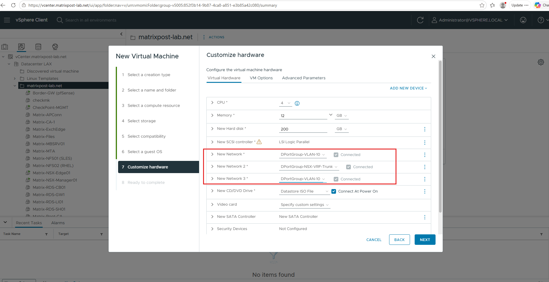
During the initial Gaia R82 installation wizard after booting from the ISO, we configure the management interface of CheckPoint-VSX (three NICs) with the following network settings.
| Setting | Value |
|---|---|
| Management interface | eth0 |
| IP address | 10.0.0.251 |
| Subnet mask | 255.255.255.0 |
| Default gateway | 10.0.0.1 (pfSense) |
| Tenant trunk | eth1 – Leave unconfigured |
| Upstream interface | eth2 – Leave unconfigured |
The remaining interfaces will be configured later during VSX provisioning, while the default gateway on eth0 provides connectivity to our existing management network and upstream pfSense firewall.
Configure the Check Point Security Management Server
After installing Check Point Gaia R82 on CheckPoint-MGMT (10.0.0.250) and rebooting the virtual machine, we can access the web-based First Time Configuration Wizard at https://10.0.0.250.
In this wizard, we will configure Gaia as a dedicated Security Management Server, which will later be used to manage our VSX Gateway, create the Virtual Systems for both NSX tenants, and configure their firewall and NAT policies through SmartConsole.
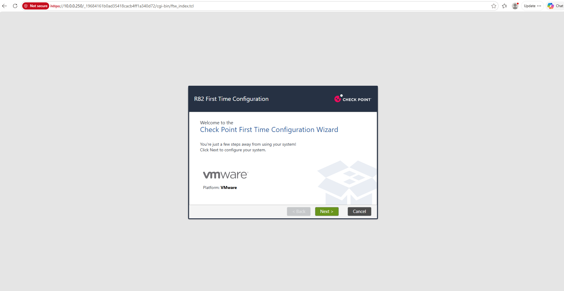
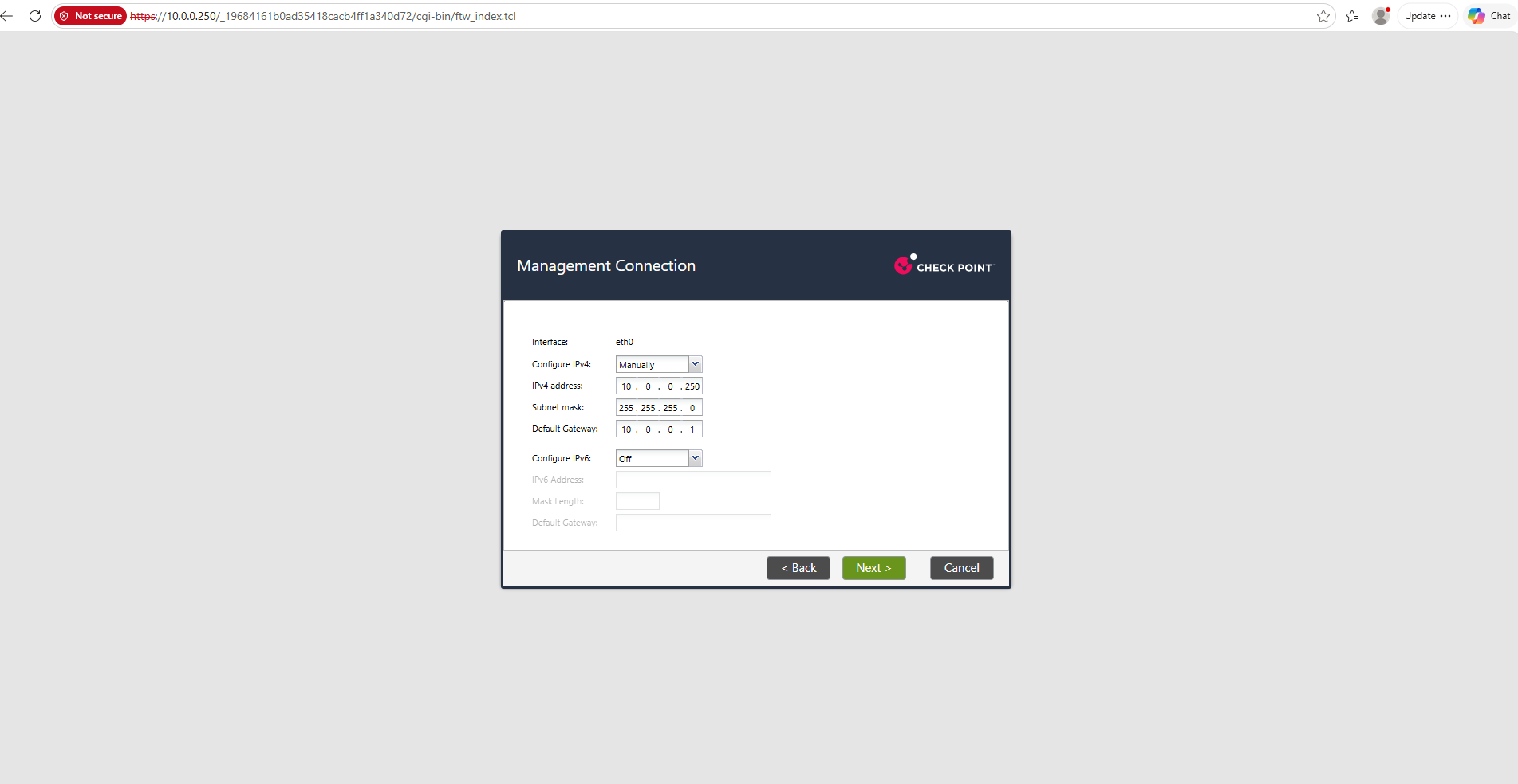
On the Deployment Options screen, we select Continue with R82 configuration to proceed with the standard Gaia installation. The other options are intended for cloud-based installation, USB installation, or recovery from an existing snapshot.
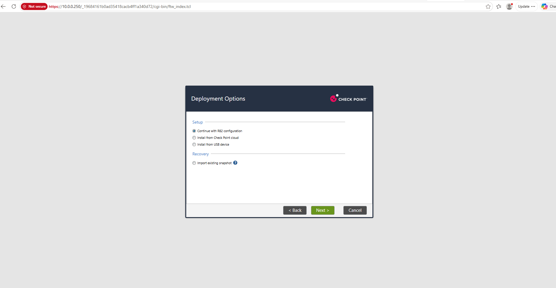
On the Management Connection screen, we configure eth0 with the static IPv4 address 10.0.0.250/24 and use our existing pfSense firewall (10.0.0.1) as the default gateway. IPv6 remains disabled, as our lab currently uses IPv4 only.
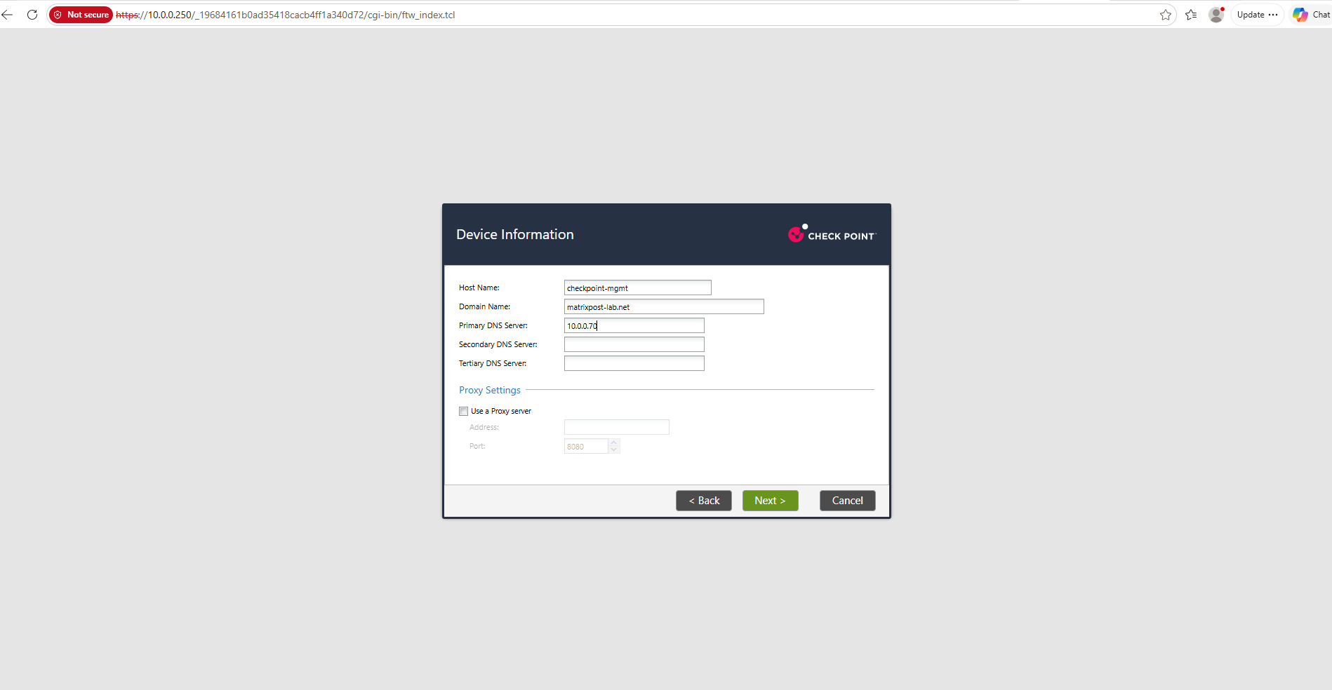
On the Device Information screen, we configure the hostname checkpoint-mgmt and the DNS domain matrixpost-lab.net. As the primary DNS server, we use our existing Active Directory DNS server (10.0.0.70), while the optional secondary DNS servers and proxy settings remain unconfigured.
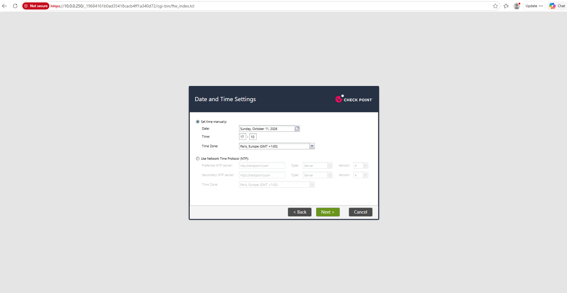
On the Date and Time Settings screen, we enable NTP synchronization to ensure consistent timestamps across the Security Management Server, VSX Gateway, and the rest of our infrastructure. We use our existing domain controller (10.0.0.70) as the NTP server and select the Central European time zone.
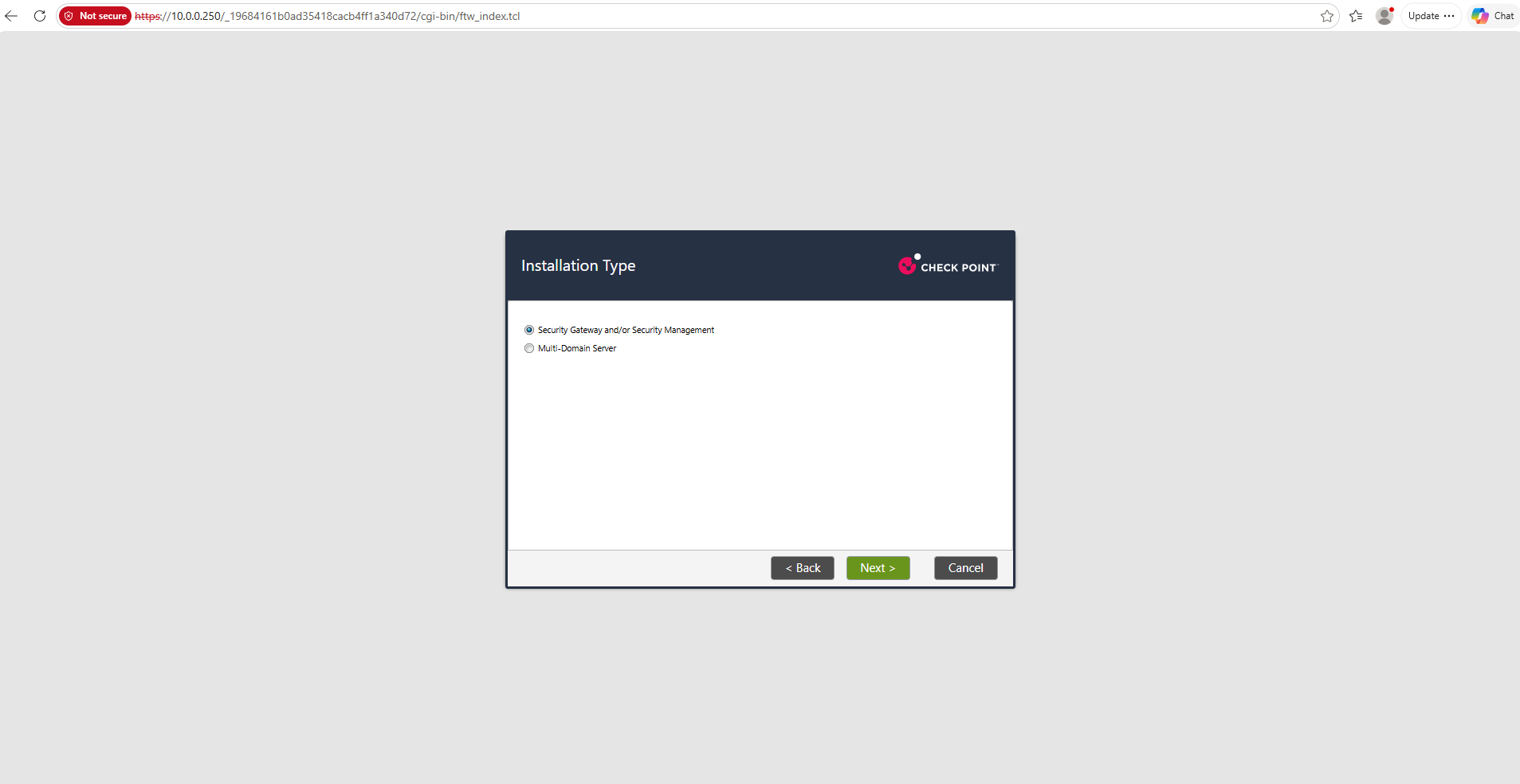
On the Installation Type screen, we select Security Gateway and/or Security Management rather than Multi-Domain Server.
In the next step, we will configure this virtual machine exclusively as a Security Management Server for our Traditional VSX environment.
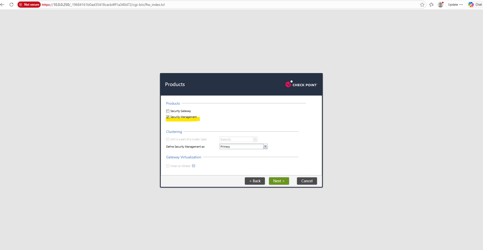
On the Products screen, we enable only Security Management and configure it as Primary, while leaving Security Gateway disabled. This creates a dedicated Security Management Server that will later manage our Traditional VSX Gateway and its Virtual Systems through SmartConsole.
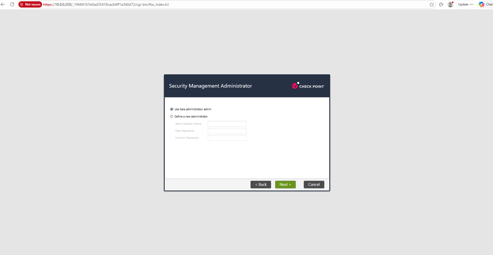
On the Security Management Administrator screen, we select Use Gaia administrator admin to reuse the existing Gaia administrator credentials for managing the Security Management Server through SmartConsole. Alternatively, a dedicated Security Management administrator can be created with separate credentials.
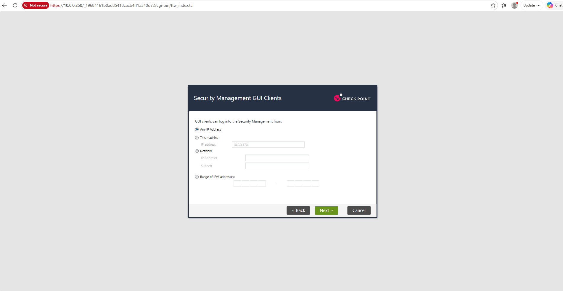
On the Security Management GUI Clients screen, we select Any IP Address to allow SmartConsole connections from any workstation that can reach the Security Management Server.
This simplifies administration in my isolated lab environment without restricting access to specific client IP addresses.
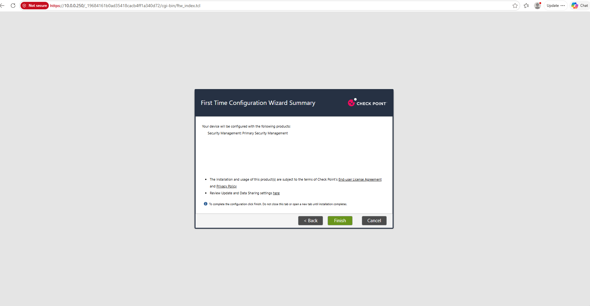
The First Time Configuration Wizard Summary confirms that the virtual machine will be configured exclusively as a Primary Security Management Server.
We click Finish to apply the configuration and initialize the management services, which may take several minutes.
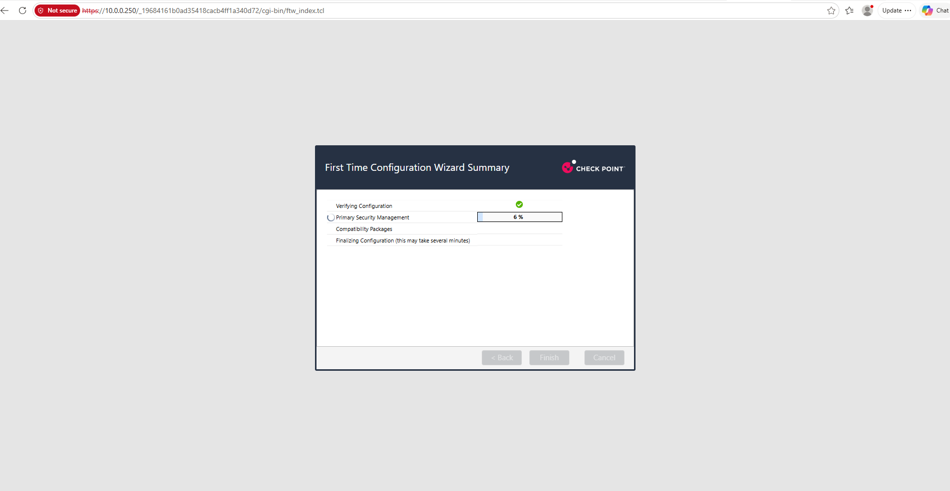
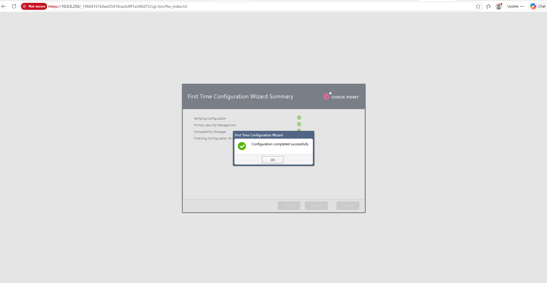
After approximately eight minutes, the First Time Configuration Wizard completes successfully, and our dedicated CheckPoint-MGMT Security Management Server is ready for administration through SmartConsole.
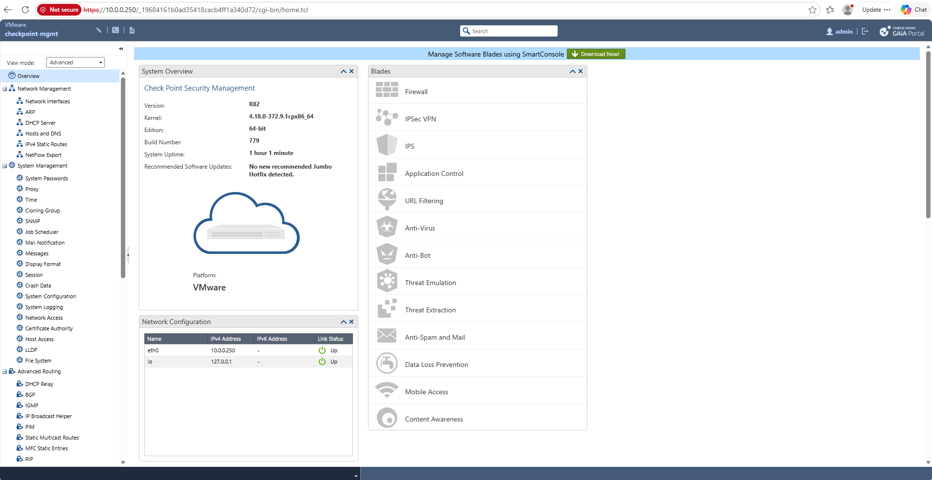
After completing the First Time Configuration Wizard, we are automatically redirected to the Gaia Portal, already authenticated as the administrator. The System Overview confirms that Check Point Security Management R82 (Build 779) is running successfully on VMware, with the management interface eth0 configured as 10.0.0.250.
The green banner at the top of the Gaia Portal offers a direct download of Check Point SmartConsole, which opens the official Check Point Support Center download page.
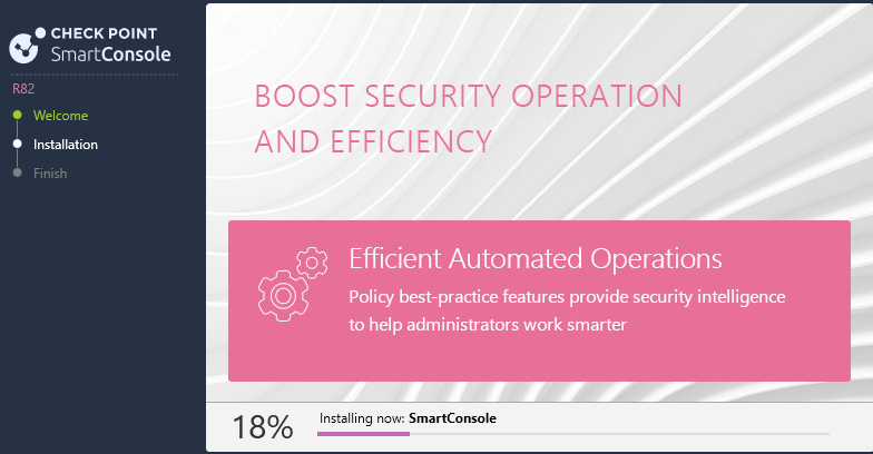
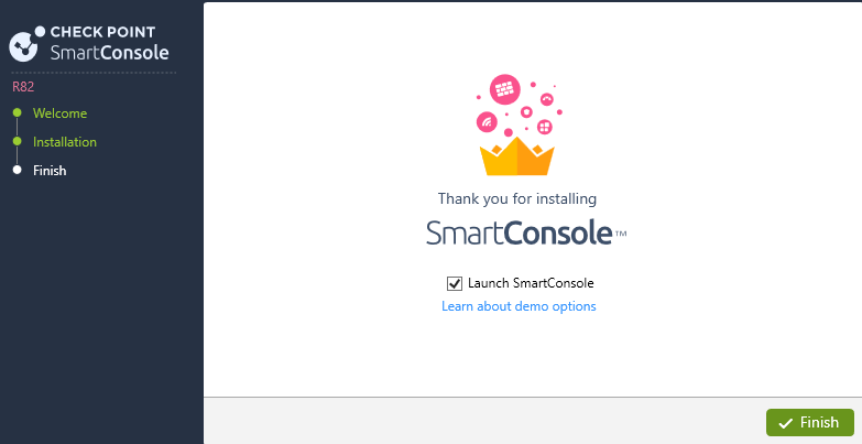
After downloading the installer from the Check Point Support Center, we install SmartConsole R82 on our Windows workstation.
SmartConsole will be used to connect to our Security Management Server and configure the VSX Gateway, Virtual Systems, and their security policies.
We can now proceed with configuring the second virtual machine, CheckPoint-VSX, as our Traditional VSX Gateway.
Configure the Check Point VSX Gateway
Unlike our dedicated Security Management Server, the second virtual machine, CheckPoint-VSX, will operate as a Traditional VSX Gateway. It will host multiple isolated Virtual Systems, each acting as an independent firewall and router for one of our NSX tenants.
For my lab, we have already deployed the virtual machine with three network interfaces:
- eth0 – Management: Connected to
DPortGroup-VLAN-10, using10.0.0.251/24for management connectivity. - eth1 – Tenant Trunk: Connected to
DPortGroup-NSX-VRF-Trunk, carrying VLANs 40 and 41 for our two NSX tenants. - eth2 – Upstream: Connected to
DPortGroup-VLAN-10, intended for north-south connectivity toward our existing pfSense router.
We first complete the Gaia First Time Configuration Wizard, selecting Security Gateway without enabling Security Management. The actual VSX Gateway and its Virtual Systems will subsequently be configured through SmartConsole.
We start the First Time Configuration Wizard on CheckPoint-VSX and configure its management interface eth0 with the static IP address 10.0.0.251/24 and our existing pfSense router (10.0.0.1) as the default gateway.
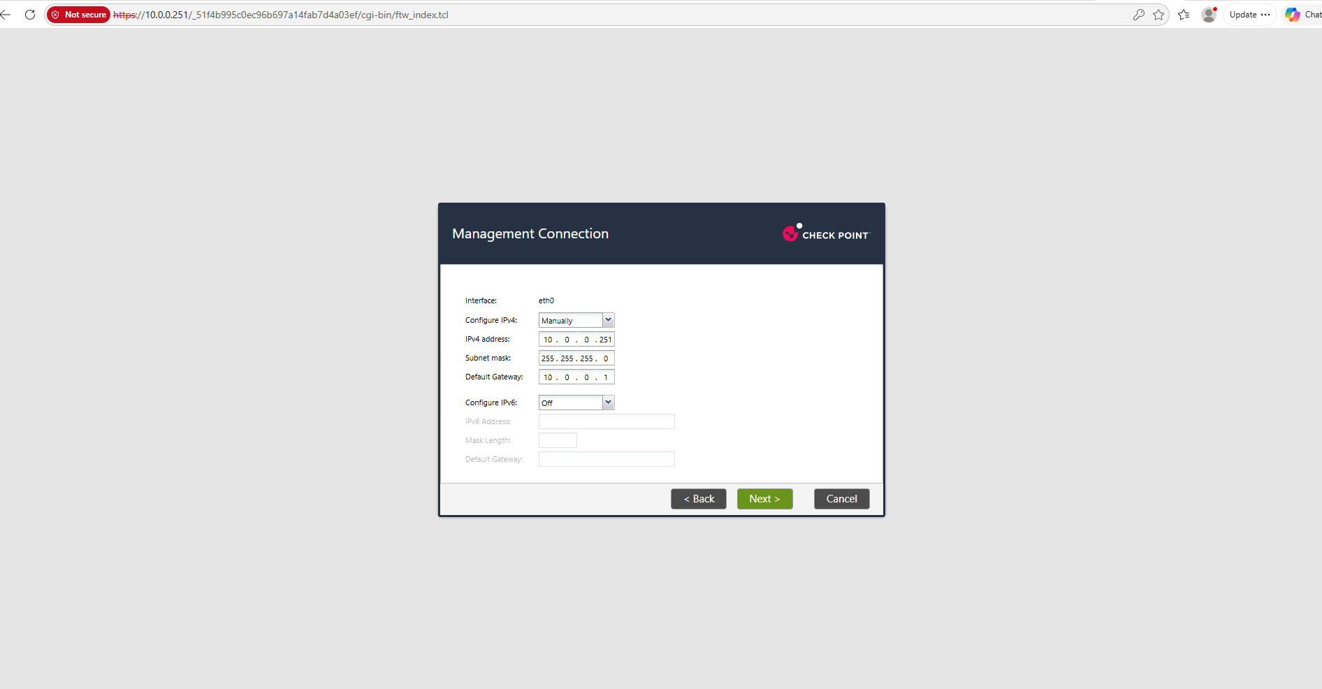
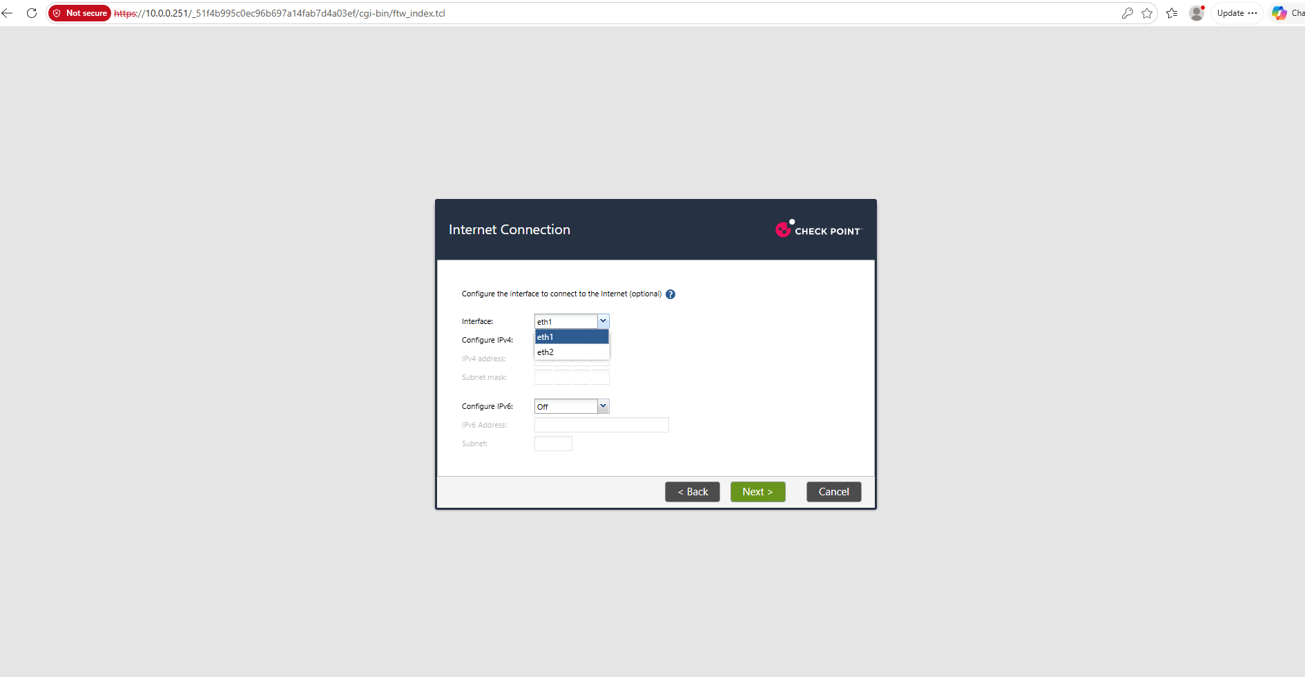
We skip the optional Internet Connection configuration because the additional interfaces eth1 and eth2 will be configured later as part of our VSX topology.
For now, only the management interface
eth0requires an IP address.
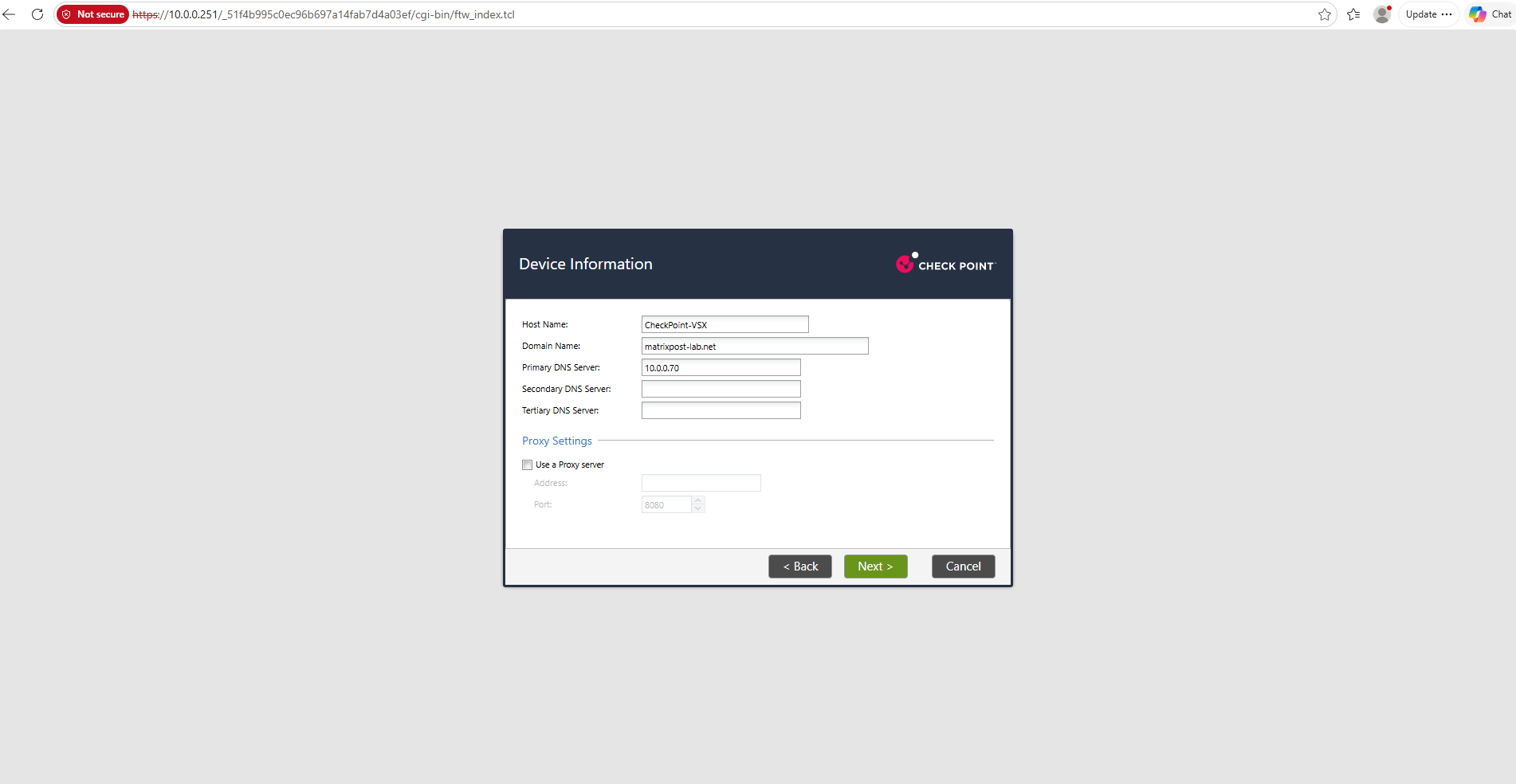
Next, we configure the hostname CheckPoint-VSX, specify my lab domain matrixpost-lab.net, and use the existing domain controller at 10.0.0.70 as the primary DNS server.
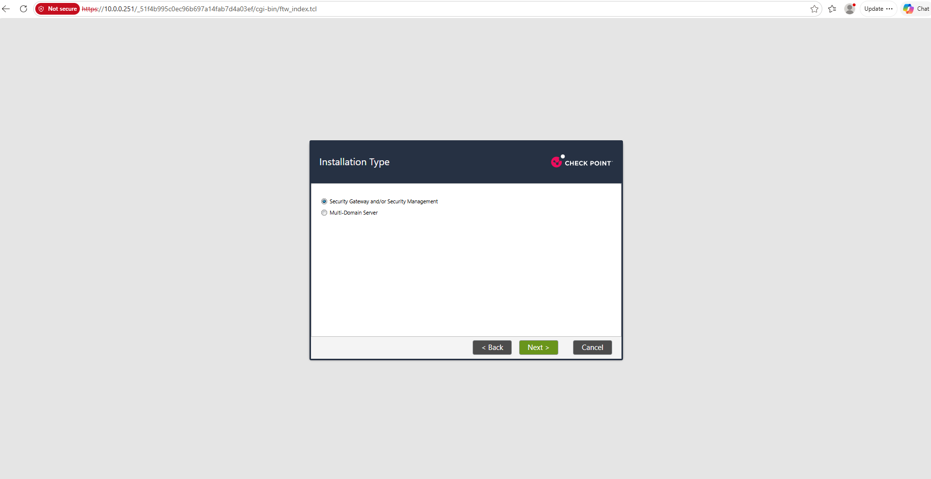
For the installation type, we select Security Gateway and/or Security Management. Unlike our first virtual machine, this system will be configured exclusively as a Security Gateway, which we will subsequently provision as a Traditional VSX Gateway through SmartConsole.
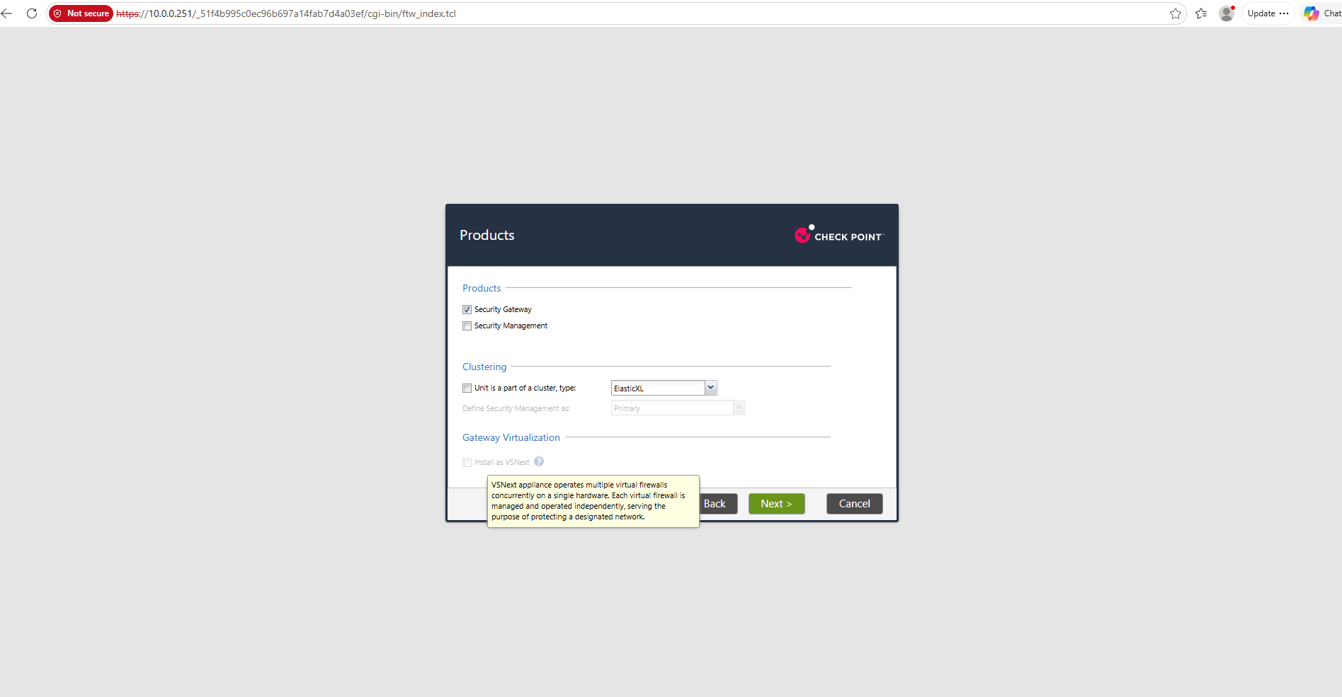
On the Products page, we enable Security Gateway only, leaving Security Management and clustering disabled.
The Install as VSNext option remains disabled because we will use Traditional VSX, which is provisioned later through SmartConsole.
The VSNext option refers to Check Point’s newer gateway virtualization architecture, which allows multiple independent virtual firewalls to operate on a single appliance.
However, Traditional VSX already provides similar core functionality by hosting multiple isolated Virtual Systems on the same gateway, each with its own interfaces, routing tables, security policies, and NAT configuration. For my lab, Traditional VSX is sufficient to isolate our two NSX tenants, even though both use the overlapping
192.168.100.0/24network.
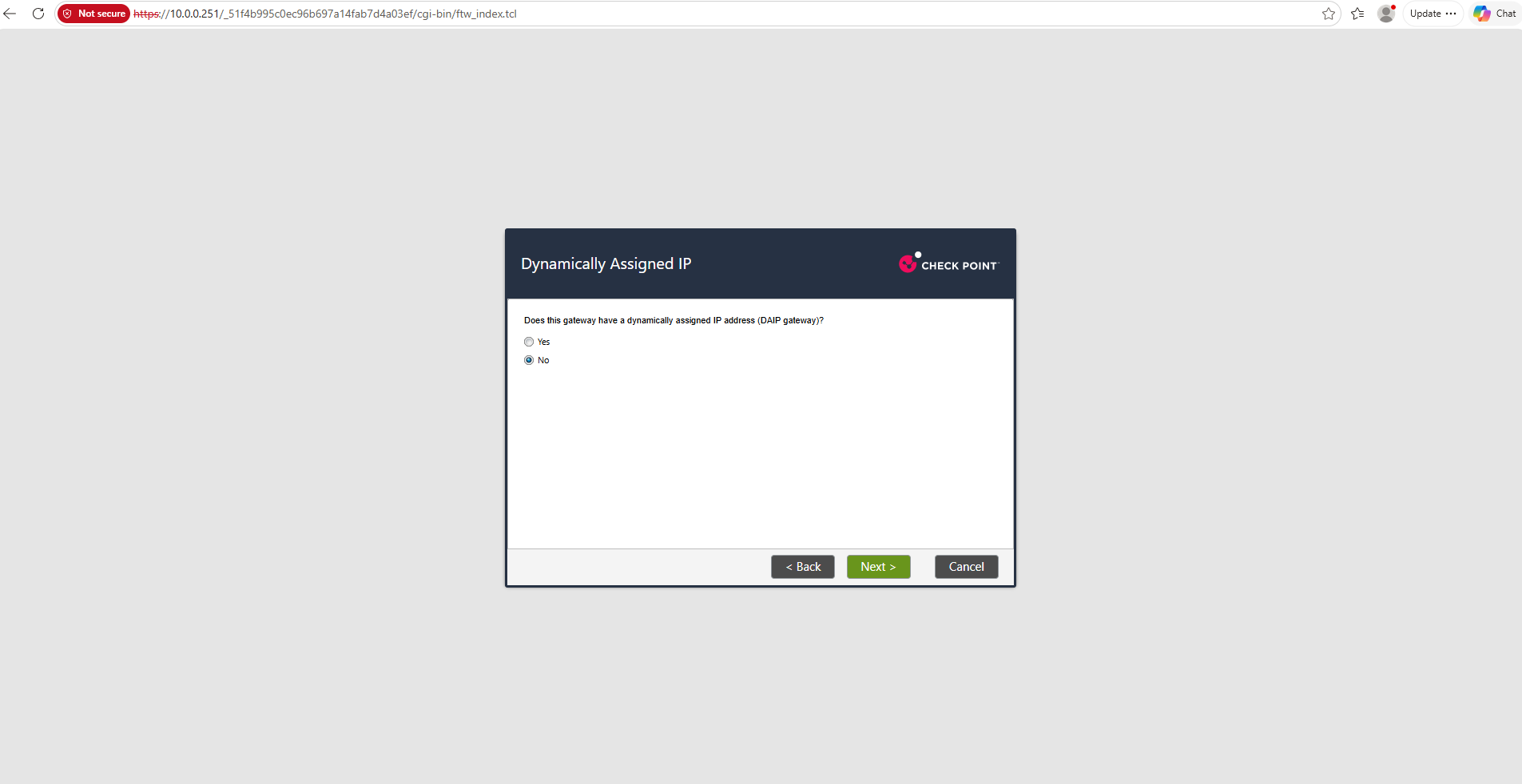
We select No for Dynamically Assigned IP (DAIP), since our VSX Gateway uses a static management IP address rather than a dynamically assigned address.
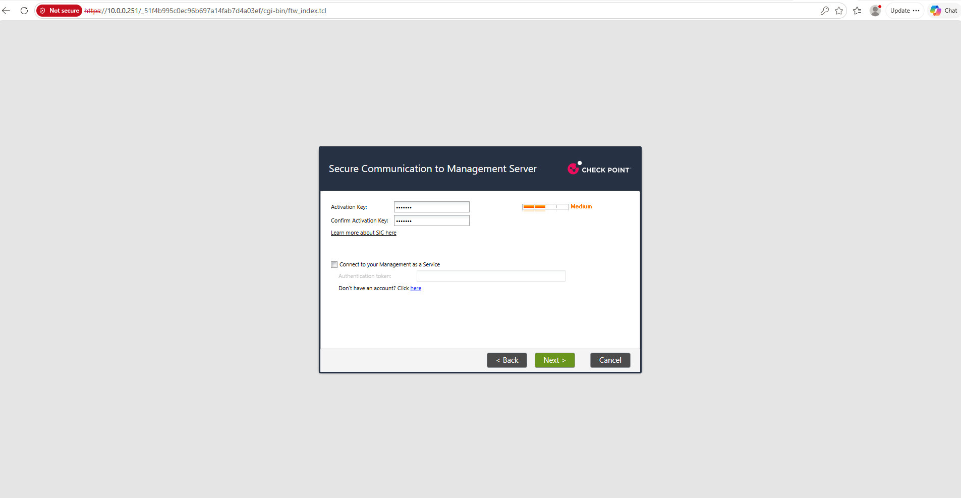
Next, we define an SIC (Secure Internal Communication) activation key, which will later be used by SmartConsole to establish a trusted, certificate-based connection between our VSX Gateway and the dedicated Security Management Server.
We leave Management as a Service disabled because our lab uses a locally deployed Management Server.
We define our own random SIC activation key to establish secure communication between the VSX Gateway and the Security Management Server. The same key must be entered later in SmartConsole to establish the initial certificate-based trust relationship.
Finally, the wizard confirms that only the Security Gateway role will be installed. We click Finish to initialize the gateway and complete its initial configuration before provisioning it as a Traditional VSX Gateway through SmartConsole.
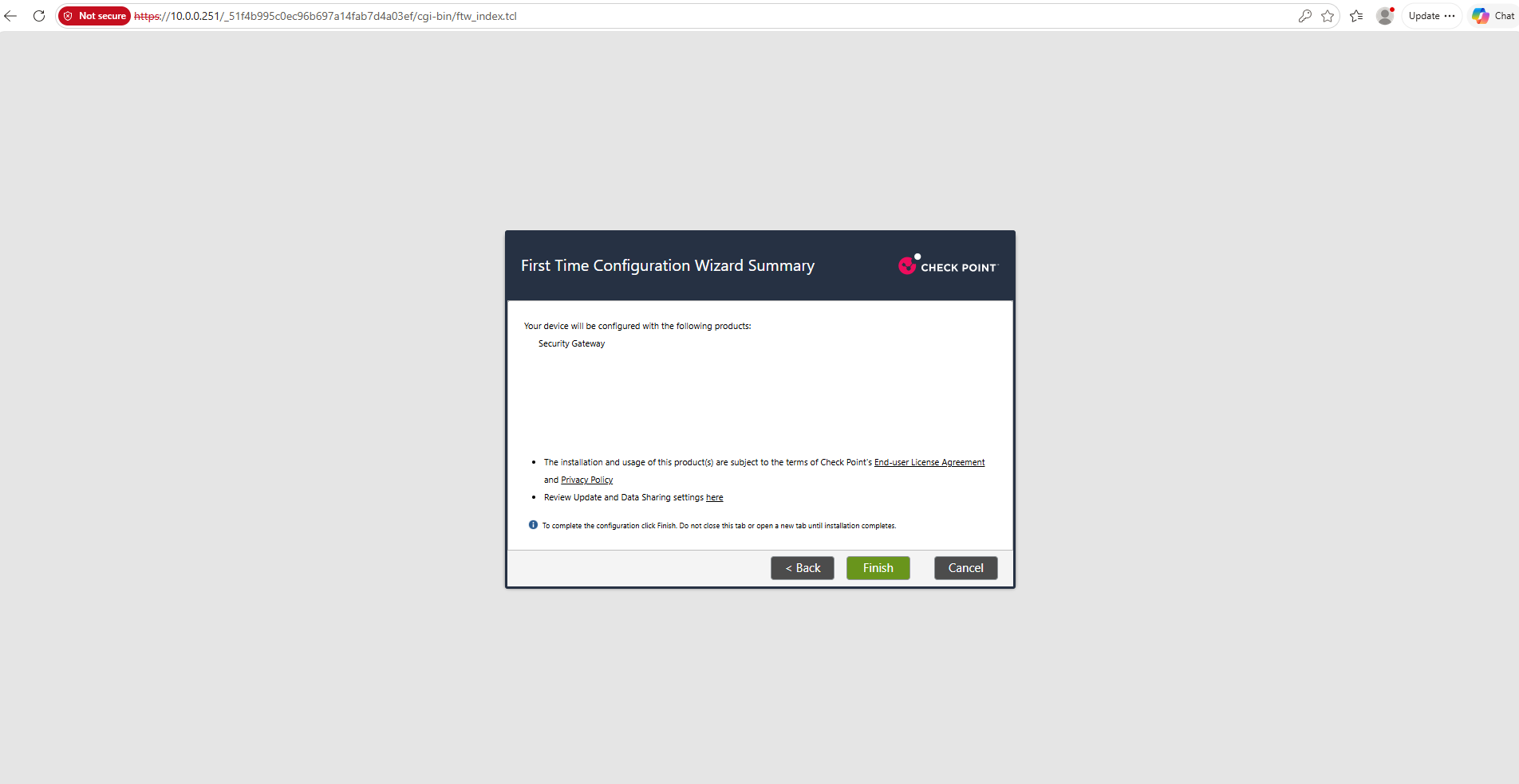
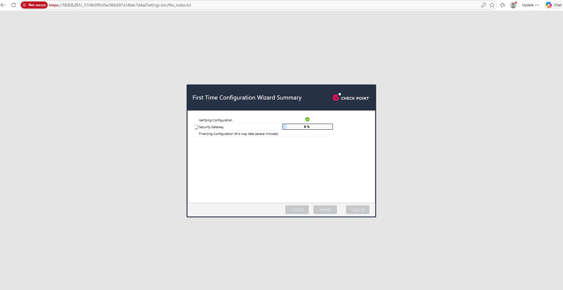
After completing the First Time Configuration Wizard, the Security Gateway requires a reboot to finalize its configuration. Once the system has restarted, we can access the Gaia Portal at https://10.0.0.251 and proceed with provisioning our Traditional VSX Gateway through SmartConsole.
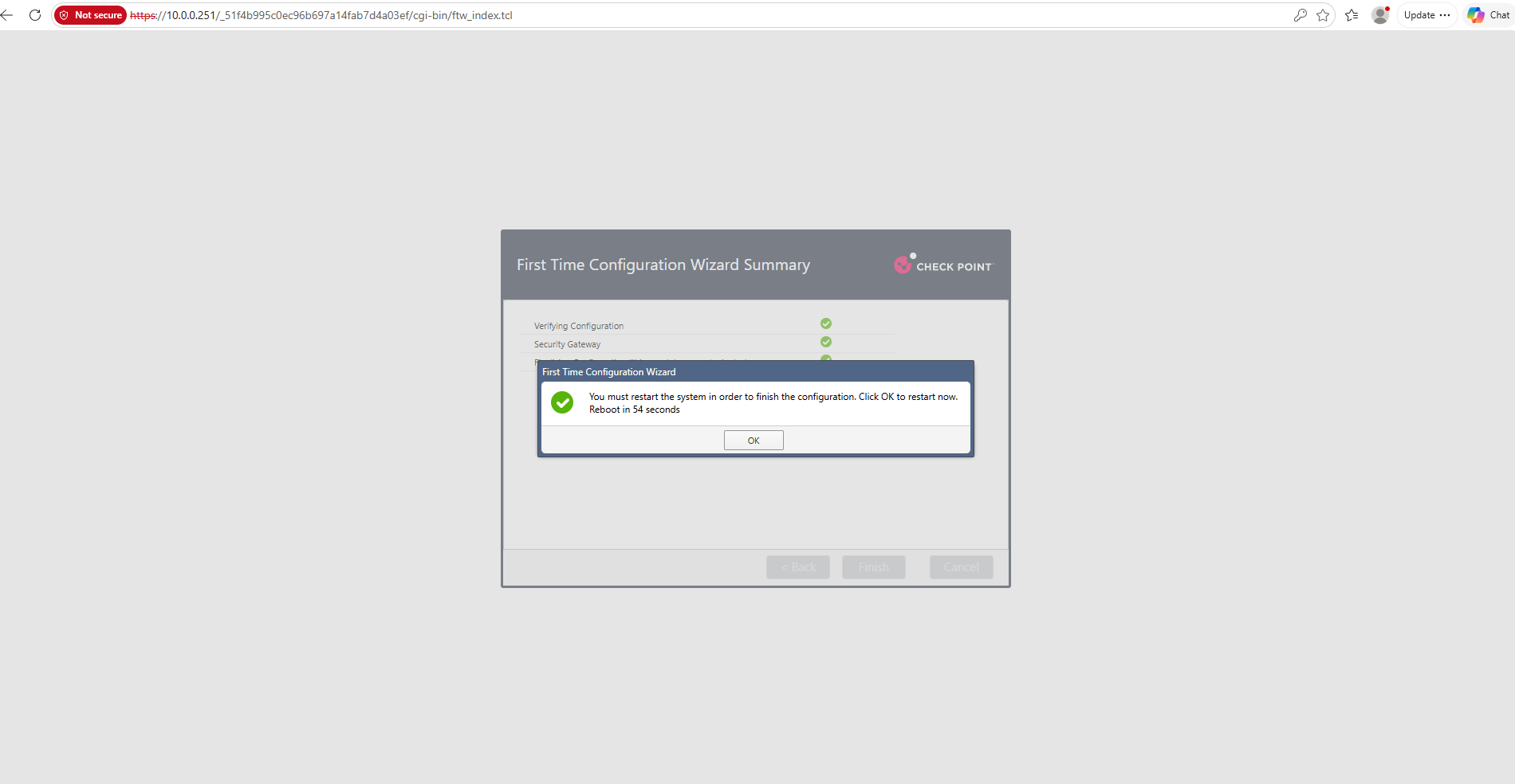
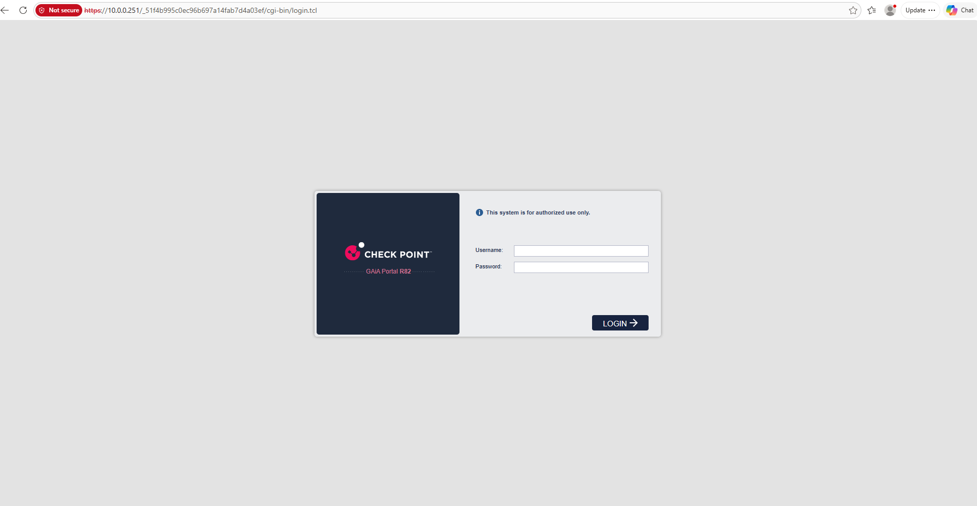
After the reboot, the Gaia Portal is accessible again at https://10.0.0.251, confirming that the initial Security Gateway configuration has completed.
We can now proceed with configuring Traditional VSX through SmartConsole.
Configure Traditional VSX Using SmartConsole
With both the Security Management Server and Security Gateway successfully deployed, we can now proceed with configuring our Traditional VSX environment using Check Point SmartConsole R82.
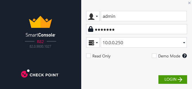
We launch SmartConsole on our Windows workstation and connect to the Security Management Server at 10.0.0.250 using our administrator credentials.
From here, we will register our VSX Gateway, establish Secure Internal Communication (SIC), and create the isolated Virtual Systems for our two NSX tenants.
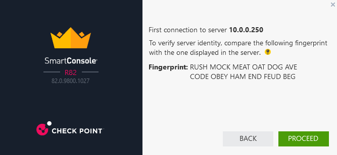
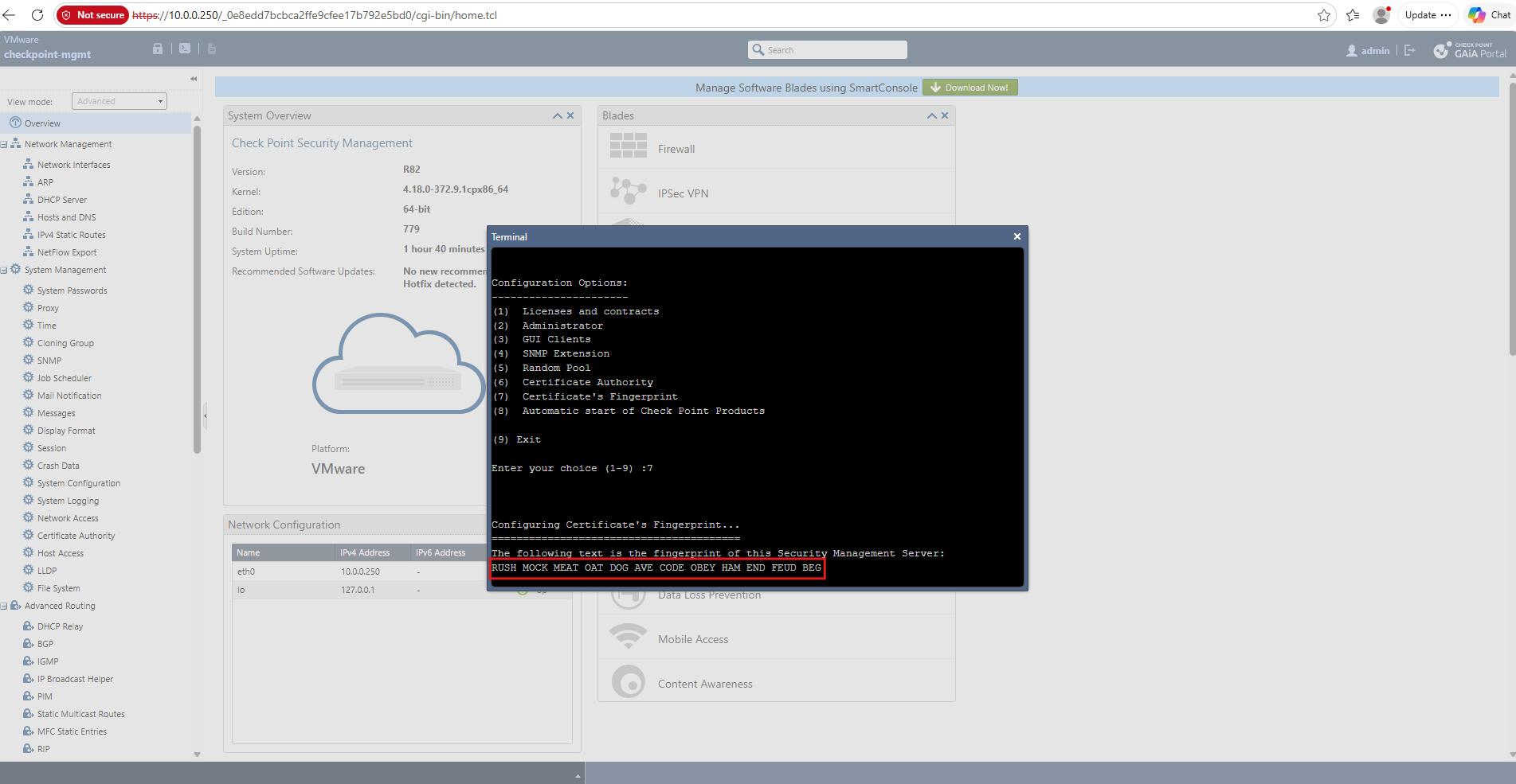
During the first connection, SmartConsole displays the Security Management Server’s certificate fingerprint for identity verification. We compare it with the fingerprint reported by our Management Server and click Proceed once they match, establishing trust for the connection.
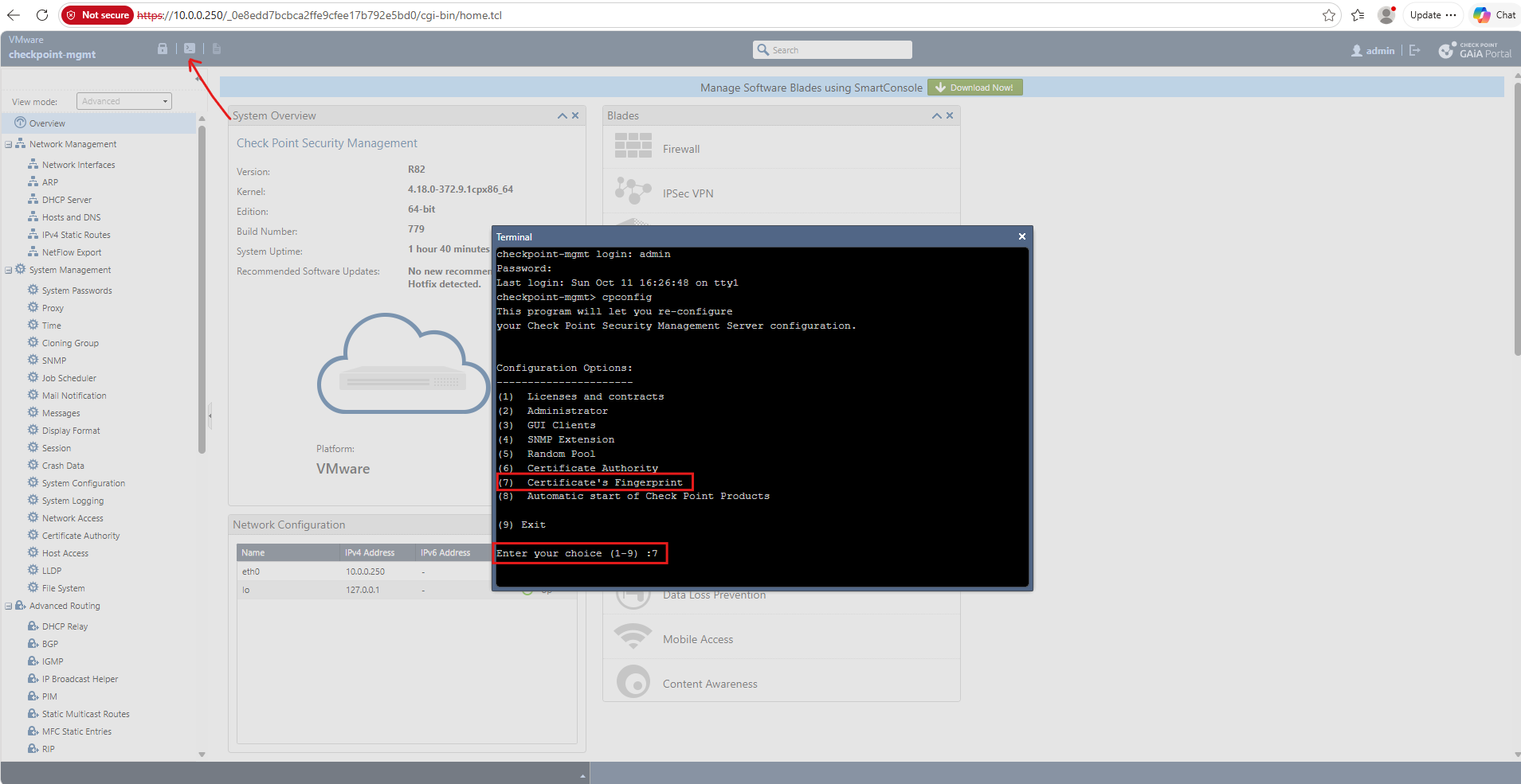
To verify the Security Management Server’s identity, we open the integrated terminal directly from the Gaia Portal and execute cpconfig.
By selecting Option 7 – Certificate’s Fingerprint, we can compare the server’s certificate fingerprint with the one displayed by SmartConsole before accepting the connection.
The fingerprint returned by cpconfig matches the one displayed during SmartConsole’s initial connection, confirming the identity of our Security Management Server.
We can now click Proceed to trust the server and continue connecting to SmartConsole.
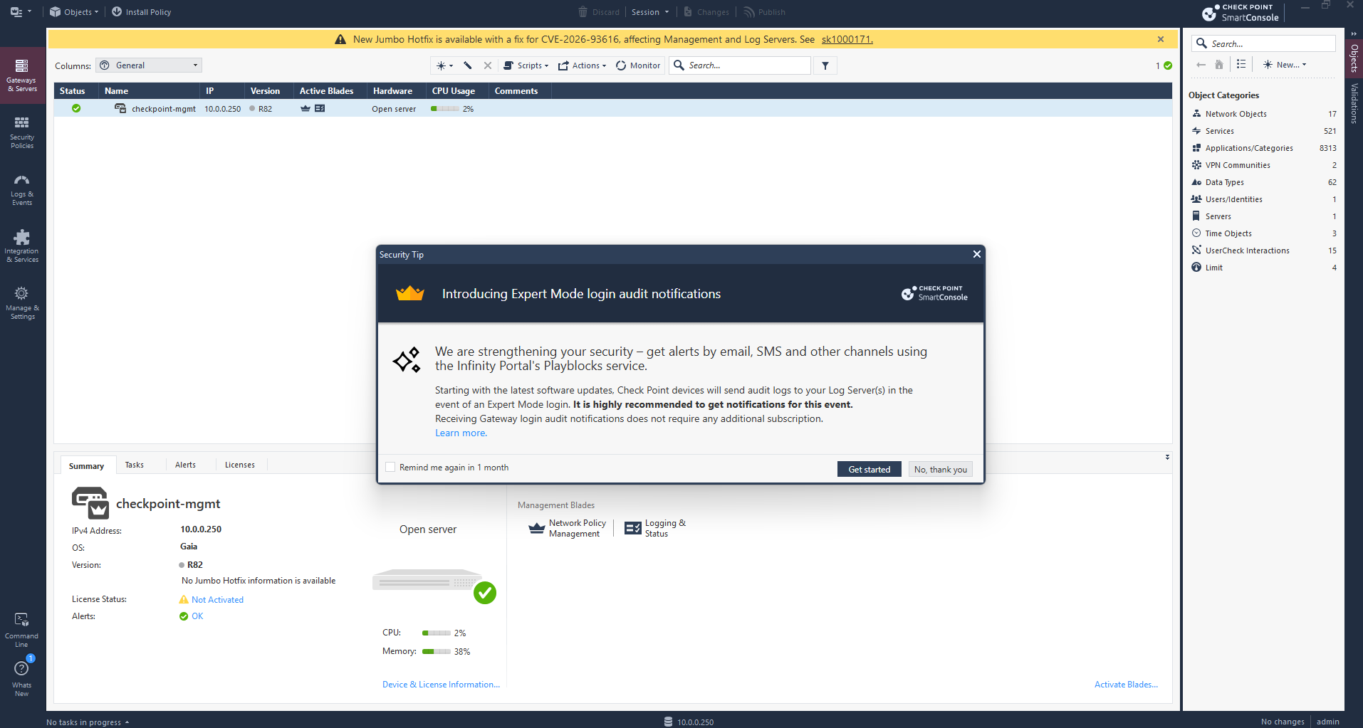
After verifying the certificate fingerprint, SmartConsole connects successfully to our Security Management Server at 10.0.0.250.
The Gateways & Servers view initially displays only our Management Server, since the VSX Gateway has not yet been registered.
Note: Jumbo Hotfix Accumulator (JHF) is Check Point’s name for a cumulative hotfix package for a specific Gaia software release, such as our R82
We should check later the recommended R82 Jumbo Hotfix and apply the appropriate security fixes..
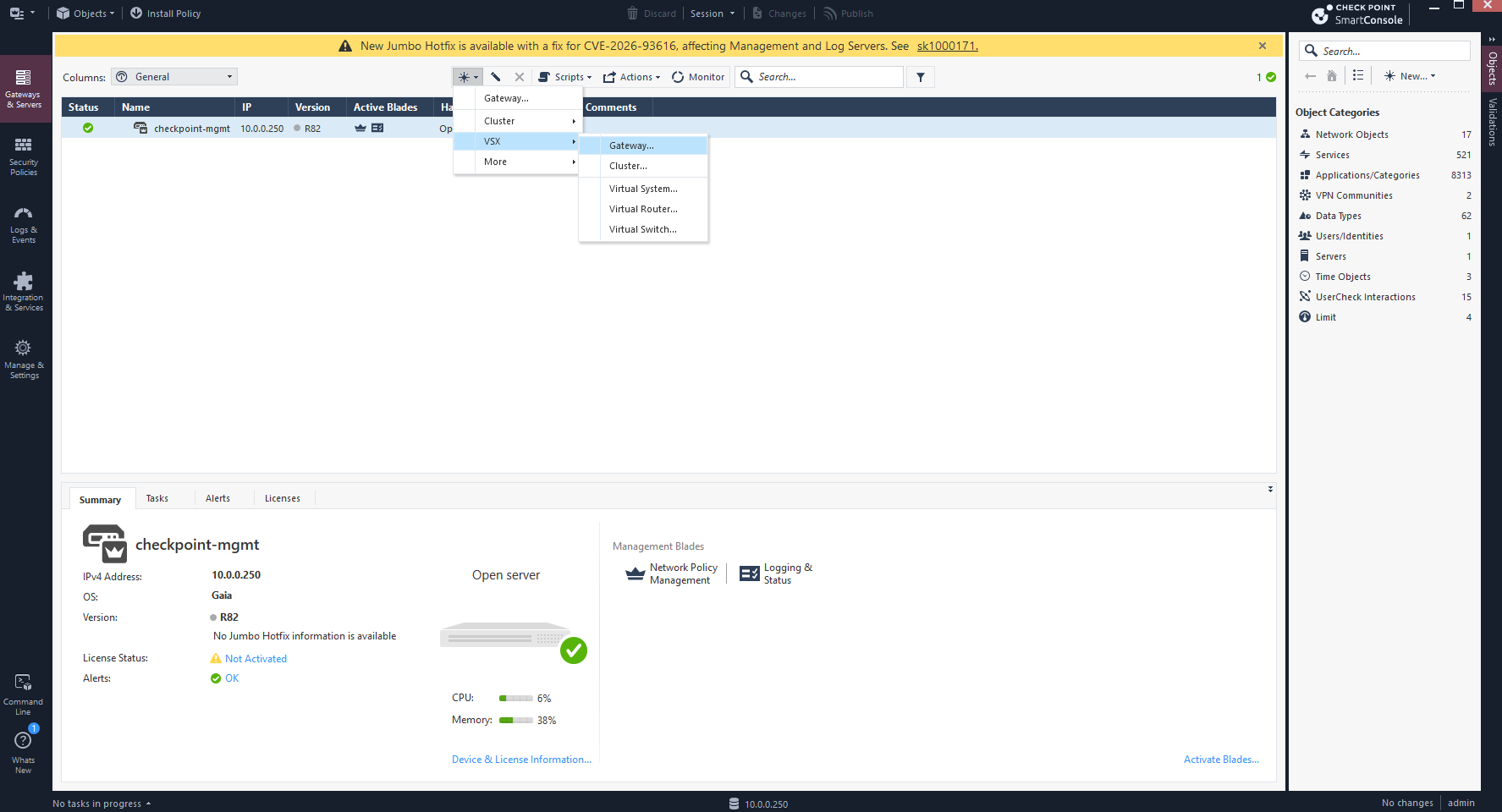
To register our Traditional VSX Gateway, we navigate to Gateways & Servers in SmartConsole and select New → VSX → Gateway. This launches the VSX Gateway configuration wizard, where we will add our previously deployed CheckPoint-VSX virtual machine.
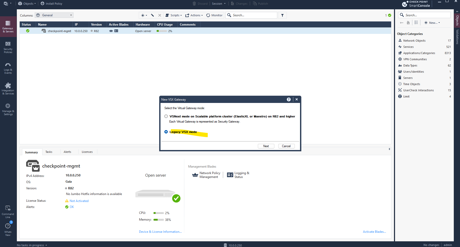
SmartConsole R82 offers two gateway virtualization modes: VSNext, designed for scalable platform clusters such as ElasticXL and Maestro, and Legacy VSX, the traditional virtualization architecture.
Since our gateway runs as a standalone virtual machine on VMware vSphere, we select Legacy VSX mode to create independent Virtual Systems for our two NSX tenants.
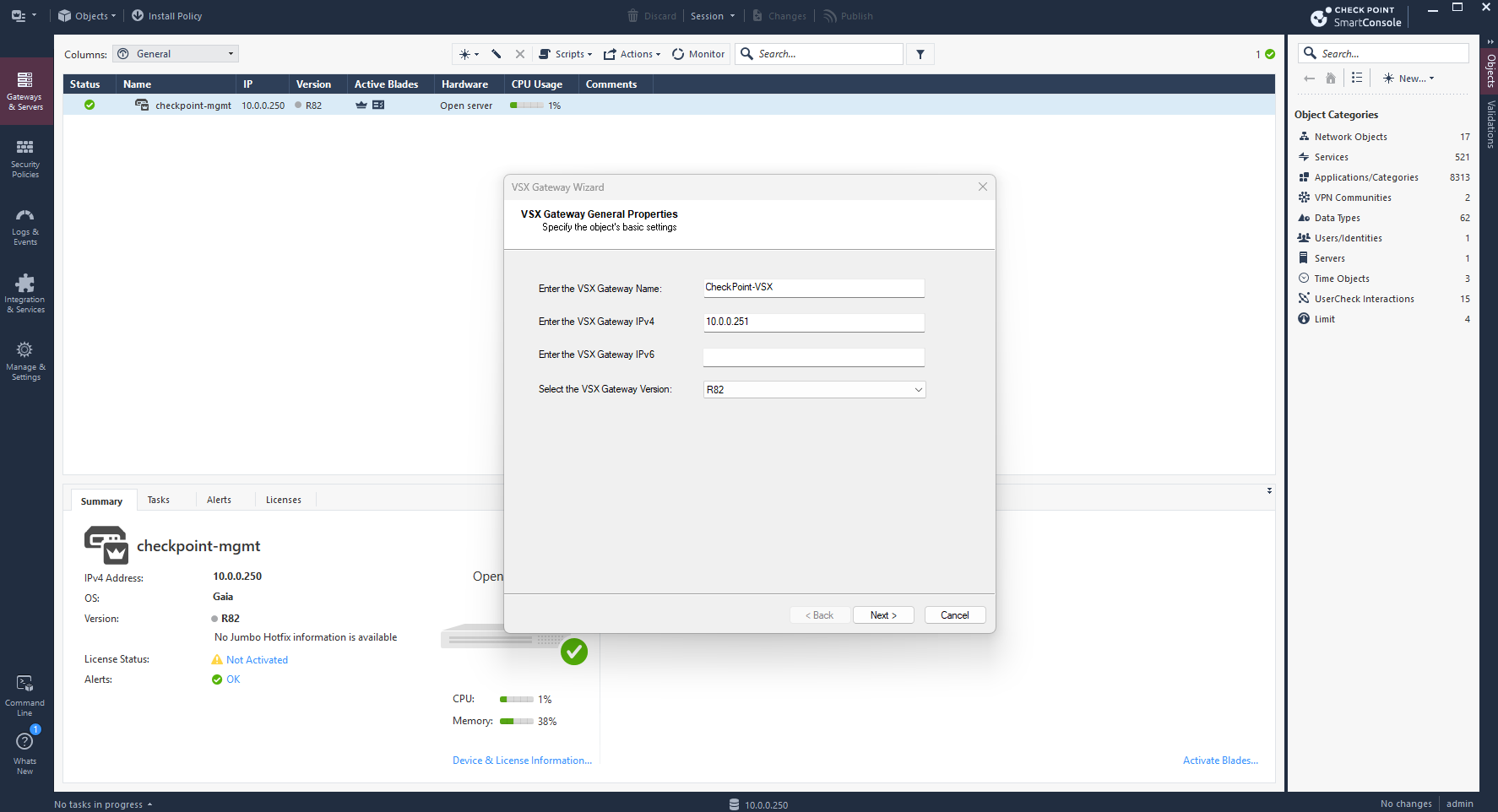
In the VSX Gateway General Properties wizard, we specify the gateway name CheckPoint-VSX and its management IP address 10.0.0.251.
We also select R82 as the gateway version to match the installed Gaia operating system, leaving IPv6 unconfigured.
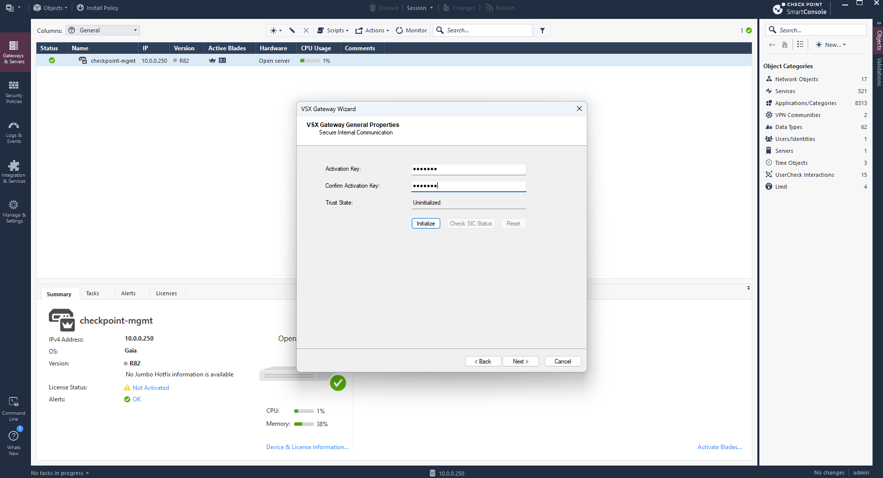
Next, we enter the same SIC activation key previously defined during the gateway’s First Time Configuration Wizard and click Initialize.
This establishes certificate-based trust between our Security Management Server and the VSX Gateway, allowing SmartConsole to manage the gateway securely.
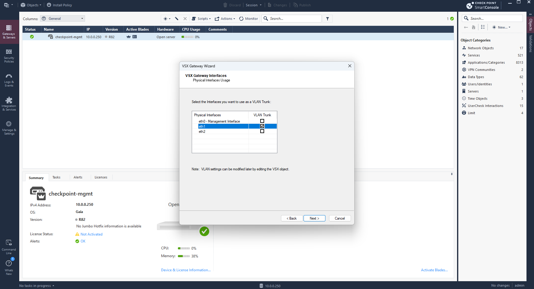
Next, we define which physical interfaces will operate as VLAN trunks.
We enable VLAN Trunk for
eth1, which connects to our existing VMware distributed port groupDPortGroup-NSX-VRF-Trunkand carries VLANs 40 and 41 for the two NSX tenants. The management interfaceeth0and upstream interfaceeth2remain untagged.
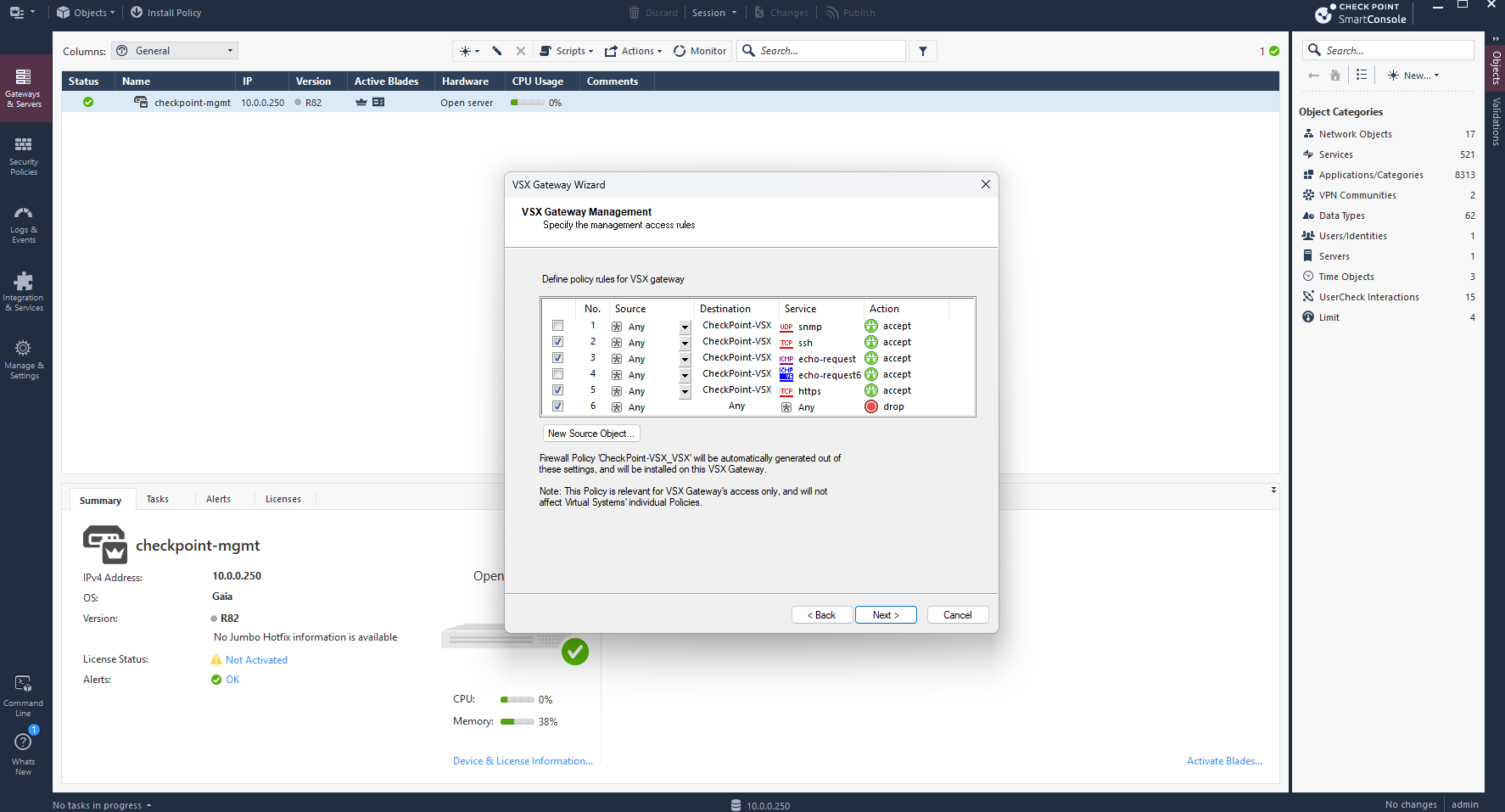
Next, we define the management access policy for our VSX Gateway. We allow SSH, ICMP, and HTTPS for administration and troubleshooting while retaining the final Drop rule for other traffic.
This policy applies only to the VSX Gateway management context; each tenant Virtual System will have its own independent security policy.
Since this is an isolated lab environment, we accept the warning and allow management access from any source IP address for simplicity.
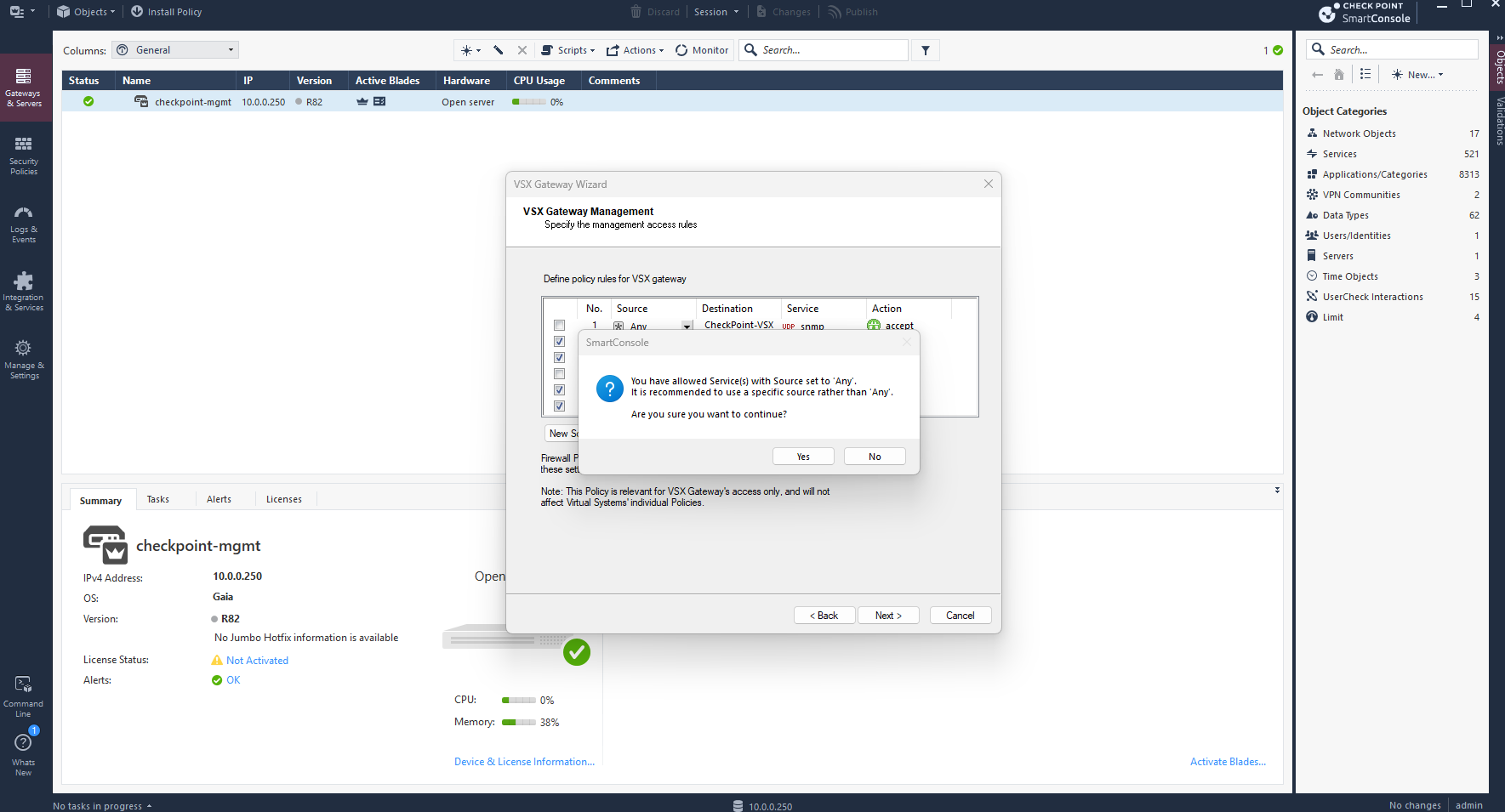
After completing the VSX Gateway Wizard, we click Finish to start provisioning the gateway. Once initialization is complete, we can create the individual Virtual Systems for TenantA and TenantB.
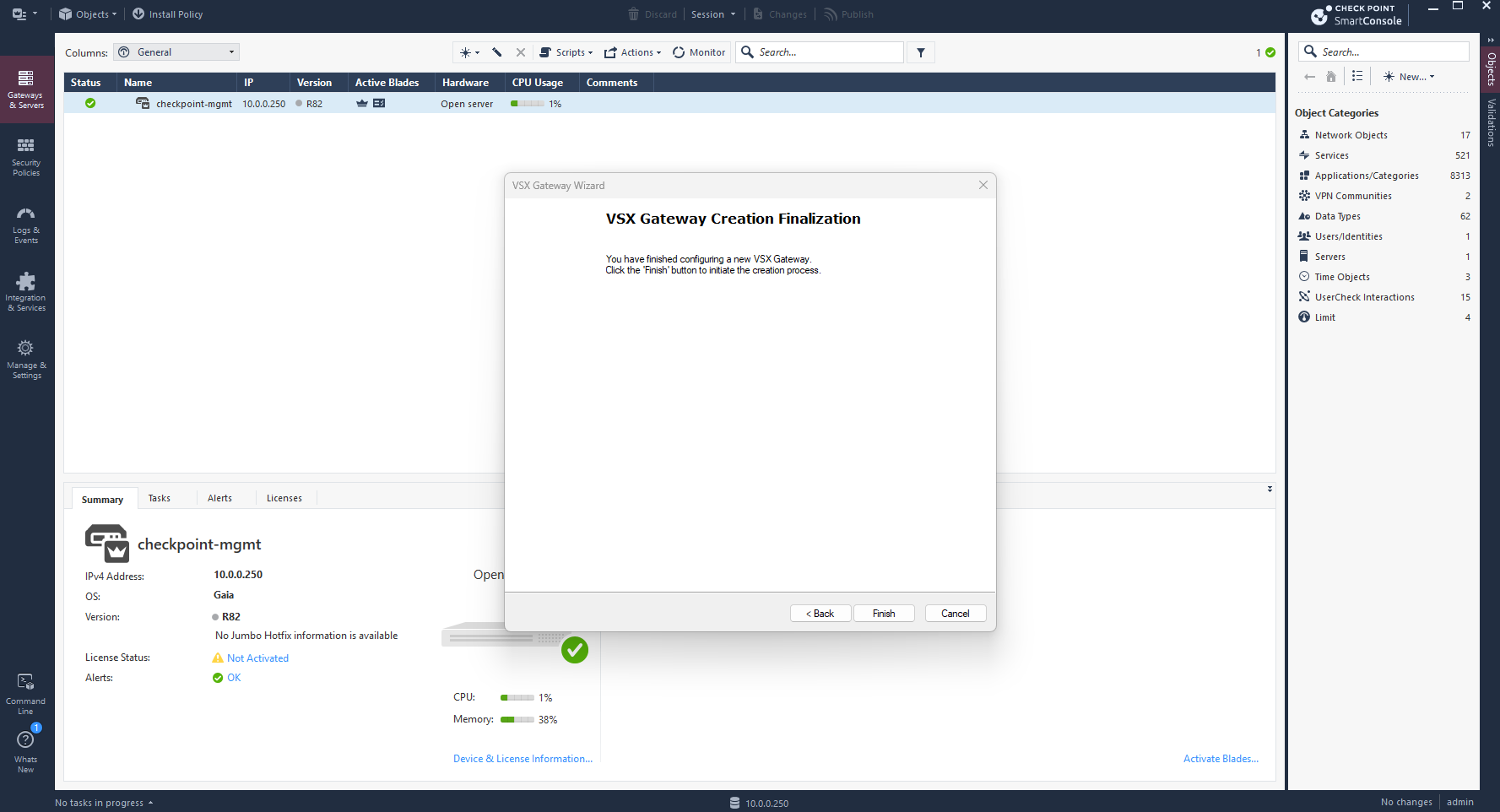
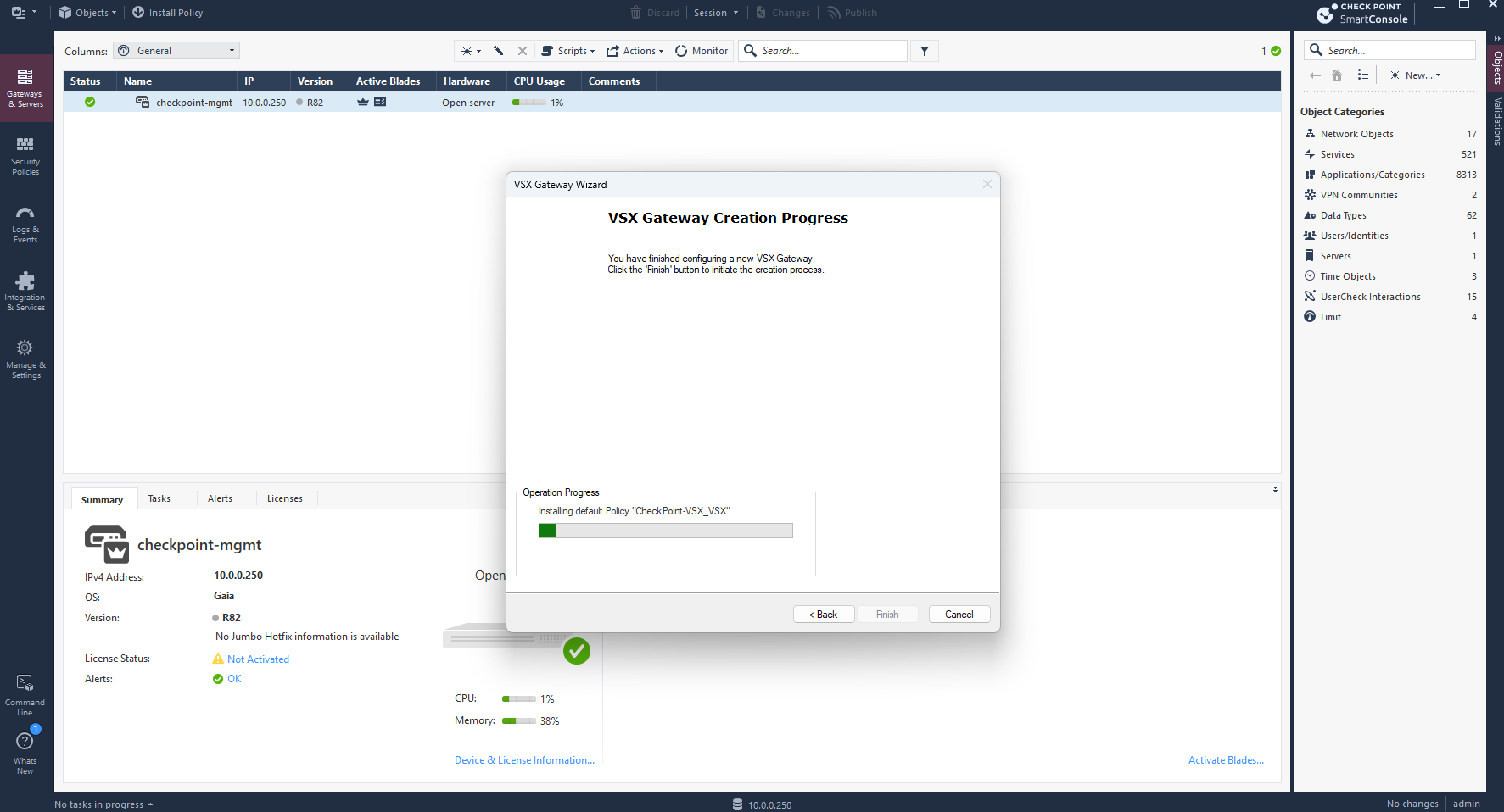
The VSX Gateway has been successfully created and is now listed in SmartConsole with a green status indicator.
Before configuring the individual Virtual Systems for TenantA and TenantB, including their overlapping IPv4 networks, we will first create a VSX Virtual Switch (VSW) to provide shared upstream connectivity toward my existing pfSense router.
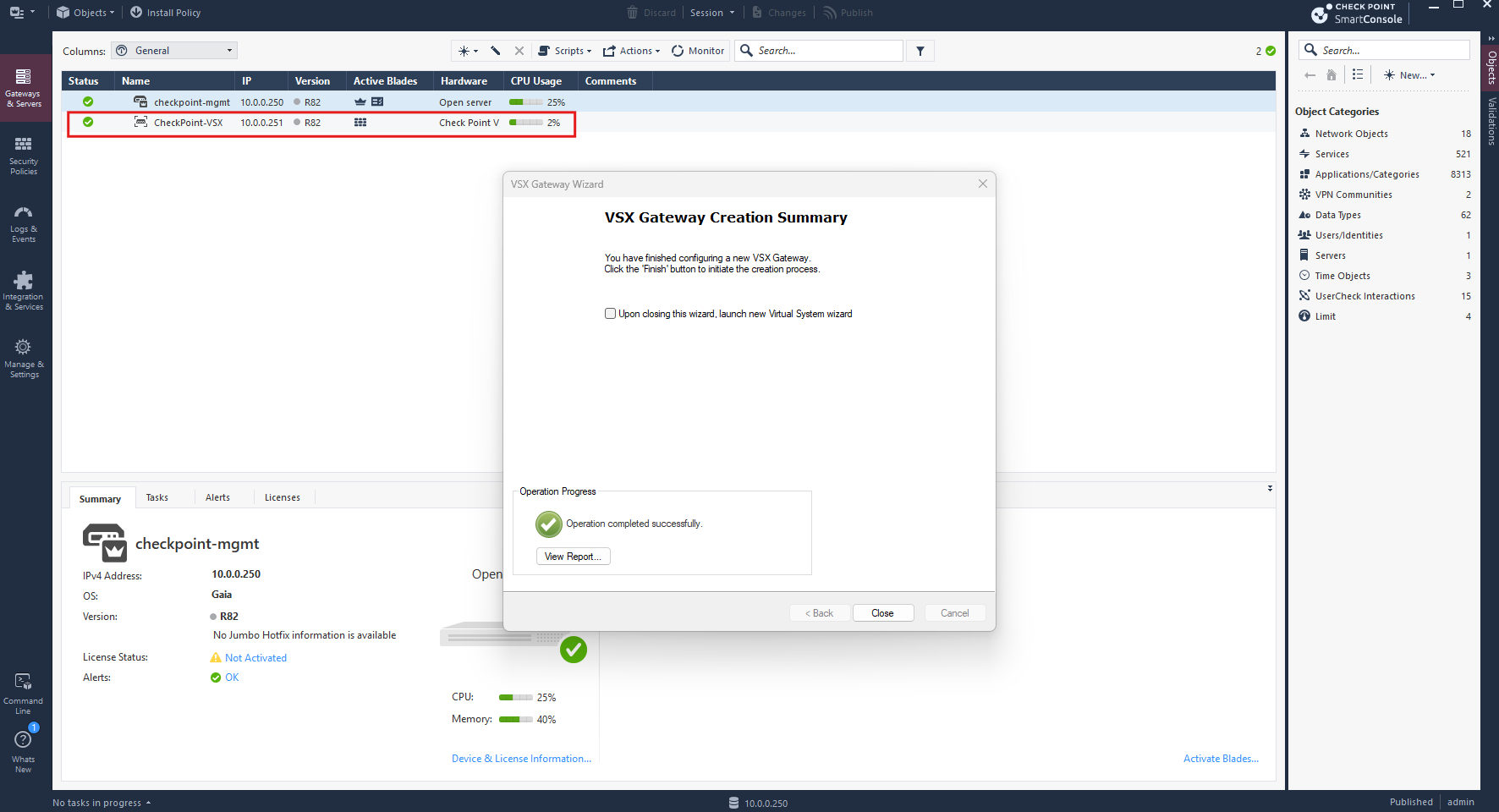
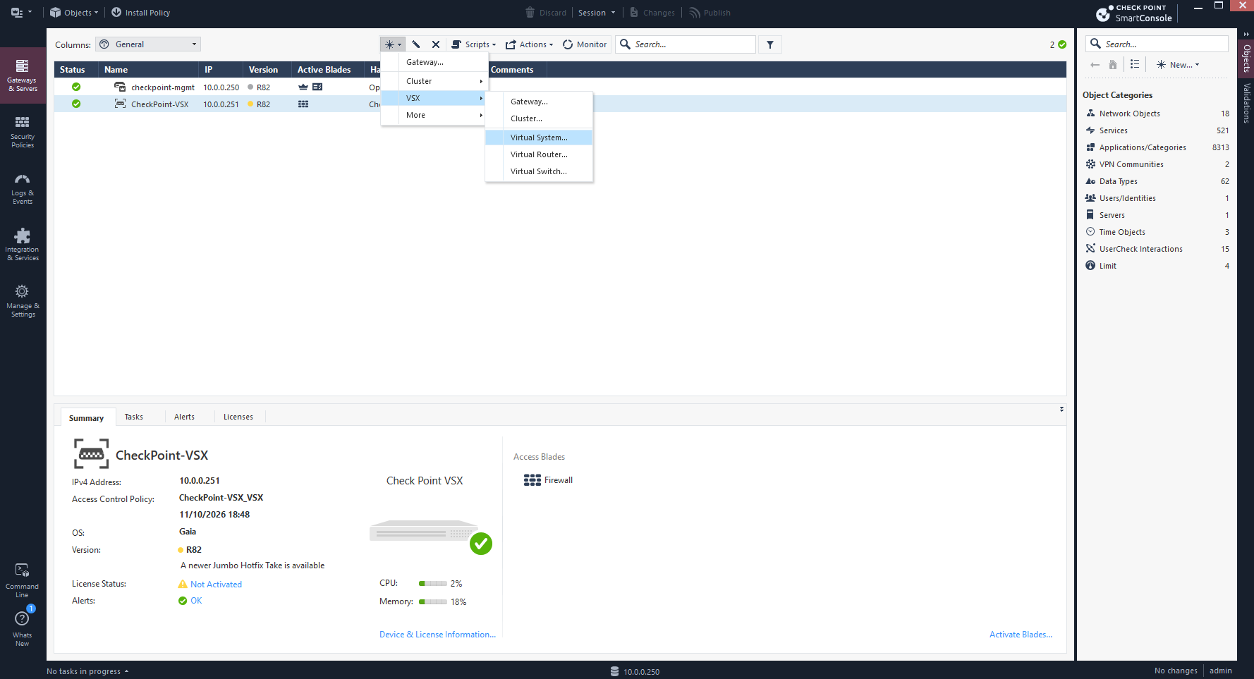
After closing the VSX Gateway Wizard, we can create additional Virtual Systems at any time in SmartConsole by navigating to Gateways & Servers → New (+) → VSX → Virtual System.
Each Virtual System will be hosted on our existing VSX Gateway and configured independently for its respective tenant.
Configure a Virtual Switch for Shared Upstream Connectivity
Before creating our tenant Virtual Systems, we first configure a VSX Virtual Switch (VSW) to provide shared upstream connectivity toward my existing pfSense router.
The Virtual Switch operates at Layer 2, allowing both tenant Virtual Systems to connect to the same physical interface (eth2) while maintaining independent routing, NAT, and firewall configurations.
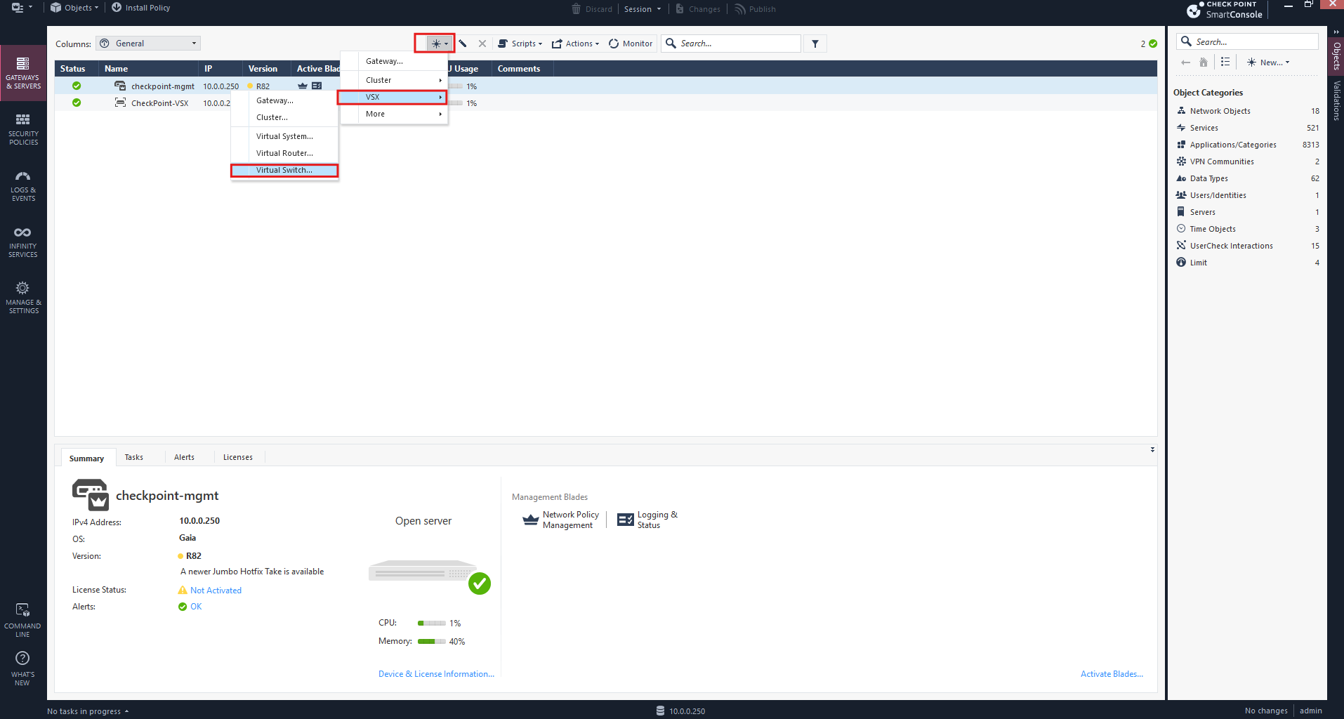
In SmartConsole, we navigate to Gateways & Servers, and click on New → VSX → Virtual Switch, and start the wizard to create a shared Layer 2 connection between our tenant Virtual Systems and the upstream pfSense network.
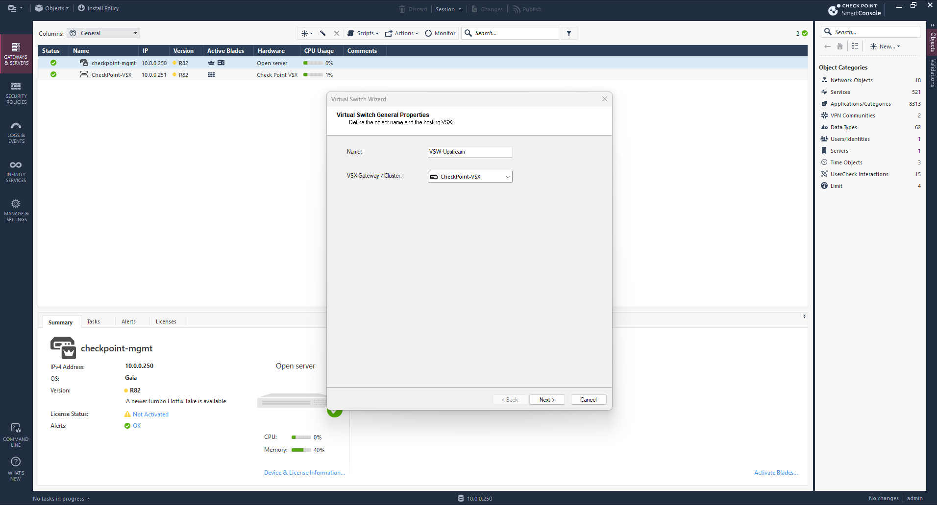
In the Virtual Switch Wizard, we enter VSW-Upstream as the name and select our existing CheckPoint-VSX gateway.
This Virtual Switch will provide shared Layer 2 connectivity for both tenant Virtual Systems toward the upstream pfSense router.
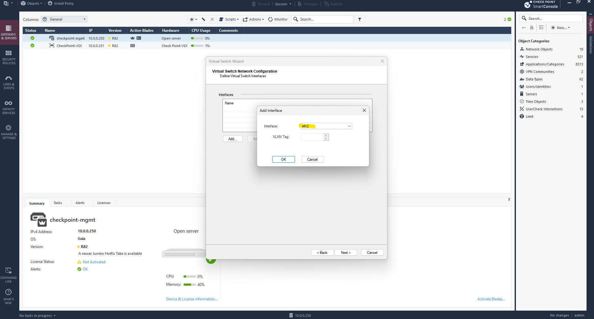
We select eth2 as the physical interface for our Virtual Switch.
No VLAN tag is required because VLAN 10 is already assigned by the vSphere Distributed Switch port group (
DPortGroup-VLAN-10), providing untagged connectivity toward my existing pfSense router at10.0.0.1.
With the physical upstream interface eth2 assigned, we click Finish to create our VSX Virtual Switch (VSW).
Since the Virtual Switch operates at Layer 2, no IP address, routing, or NAT configuration is required.
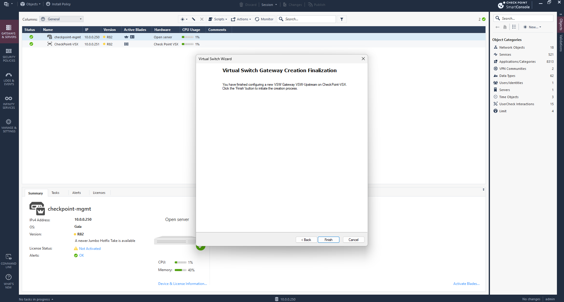
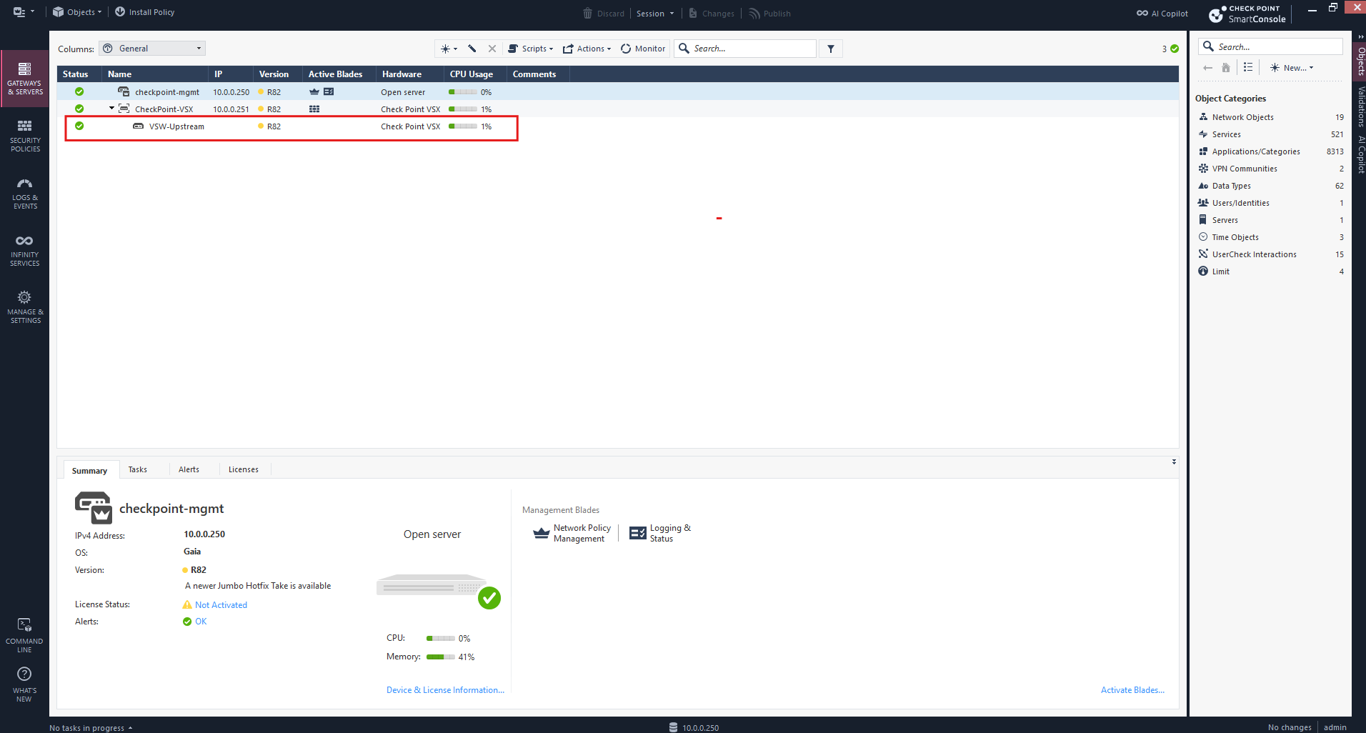
Our VSX Virtual Switch (VSW-Upstream) has been successfully created and is now listed beneath the Check Point VSX Gateway in SmartConsole.
With the shared Layer 2 upstream connection in place, we can proceed with creating the individual Virtual Systems for TenantA and TenantB.
Create Virtual Systems for TenantA and TenantB
With our Check Point VSX Gateway successfully deployed and registered in SmartConsole, we can now create the individual Virtual Systems for TenantA and TenantB. Each Virtual System operates as an independent virtual firewall with its own routing table, security policies, and NAT configuration, allowing both tenants to use the same overlapping IPv4 address space of 192.168.100.0/24.
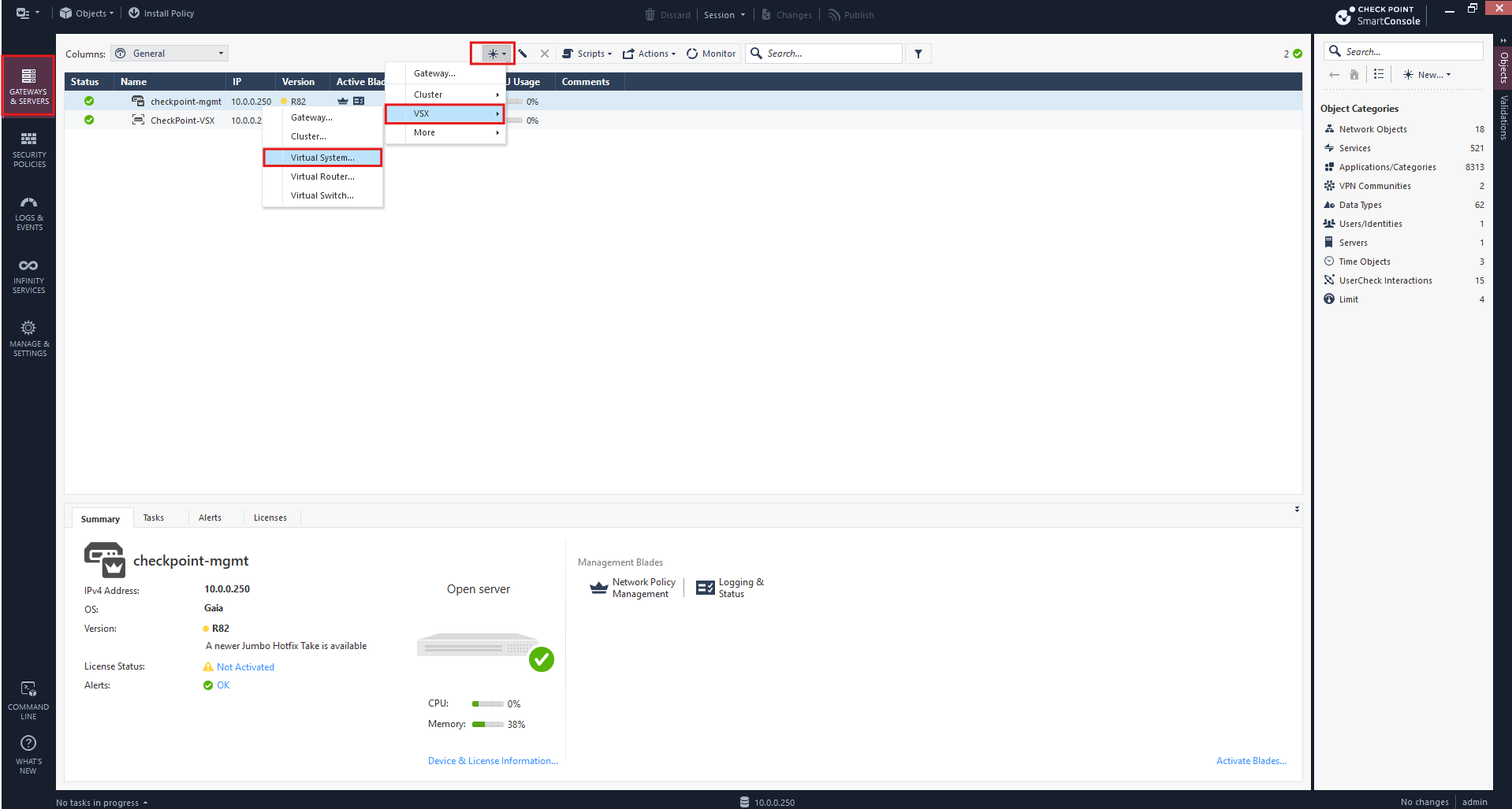
Open SmartConsole → Gateways & Servers → New (+) → VSX → Virtual System
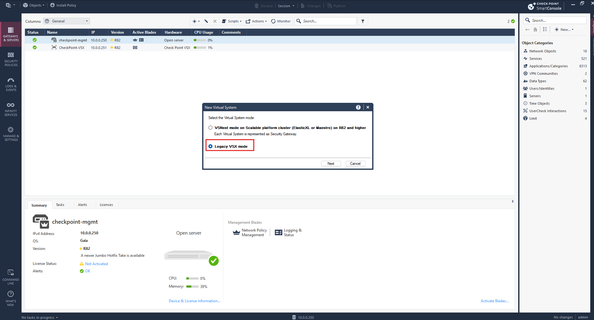
Since our gateway uses Traditional VSX on VMware vSphere, we select Legacy VSX mode rather than VSNext, which is designed for supported scalable platform clusters such as Maestro and ElasticXL.
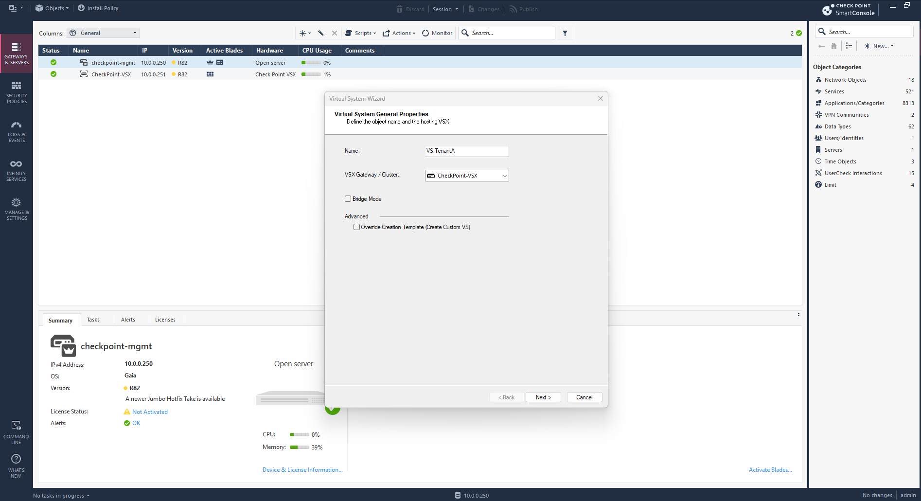
We name our first Virtual System VS-TenantA and select the existing CheckPoint-VSX gateway as its host.
Bridge Mode remains disabled because the Virtual System will operate as a routed firewall, providing independent routing, security policies, and NAT for TenantA.
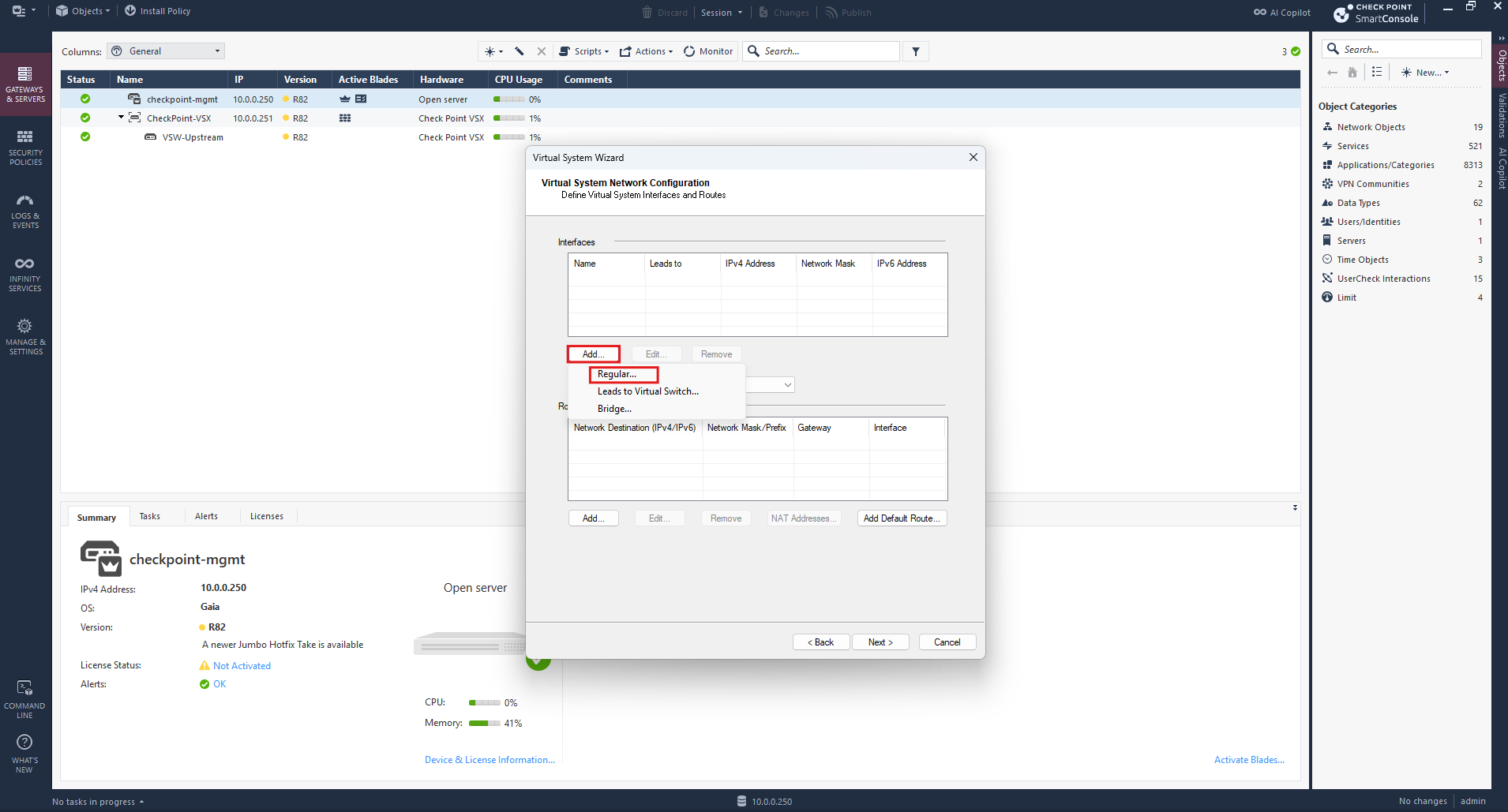
Now we’re at Virtual System Network Configuration, where we define the interfaces and routing for VS-TenantA.
Select Add → Regular….
When configuring the Virtual System interfaces, we can choose between Regular, Leads to Virtual Switch, and Bridge.
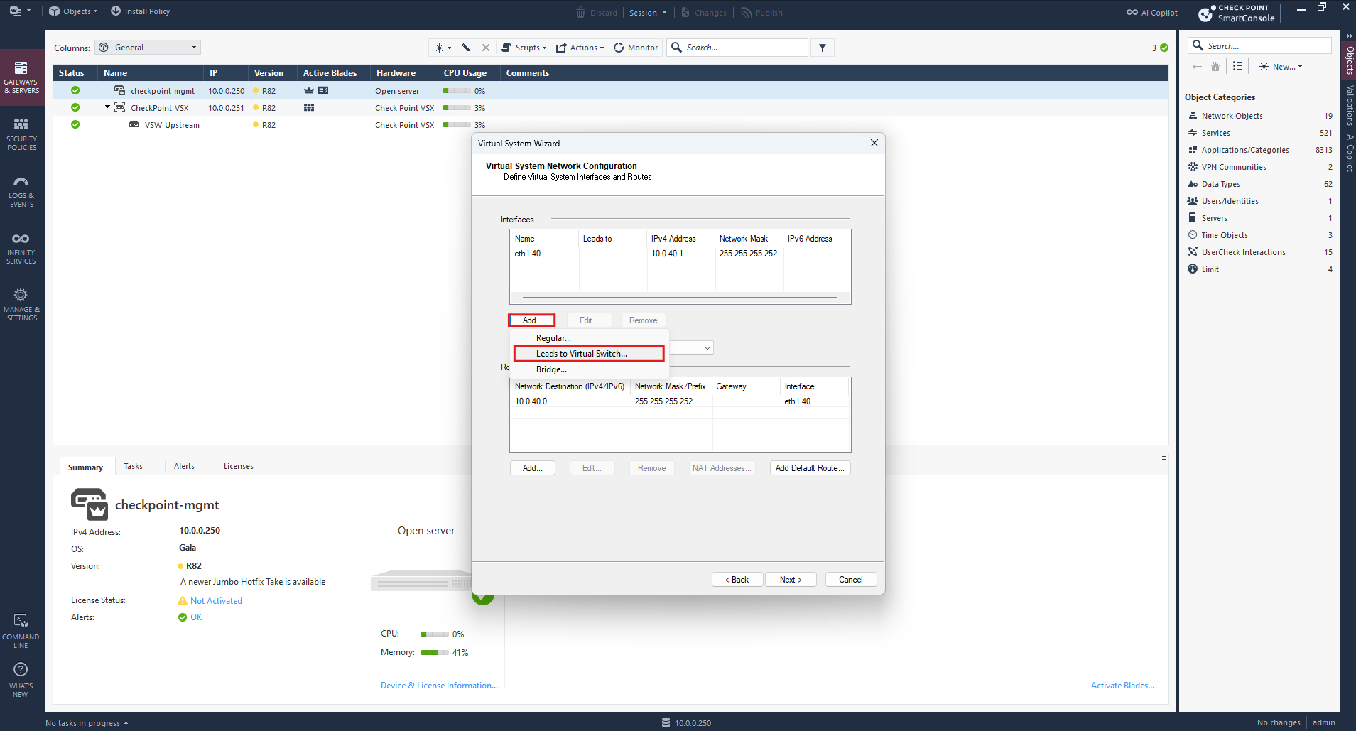
We use Regular for the tenant-facing VLAN interface and Leads to Virtual Switch to connect the Virtual System to our previously configured
VSW-Upstreamfor north-south connectivity.
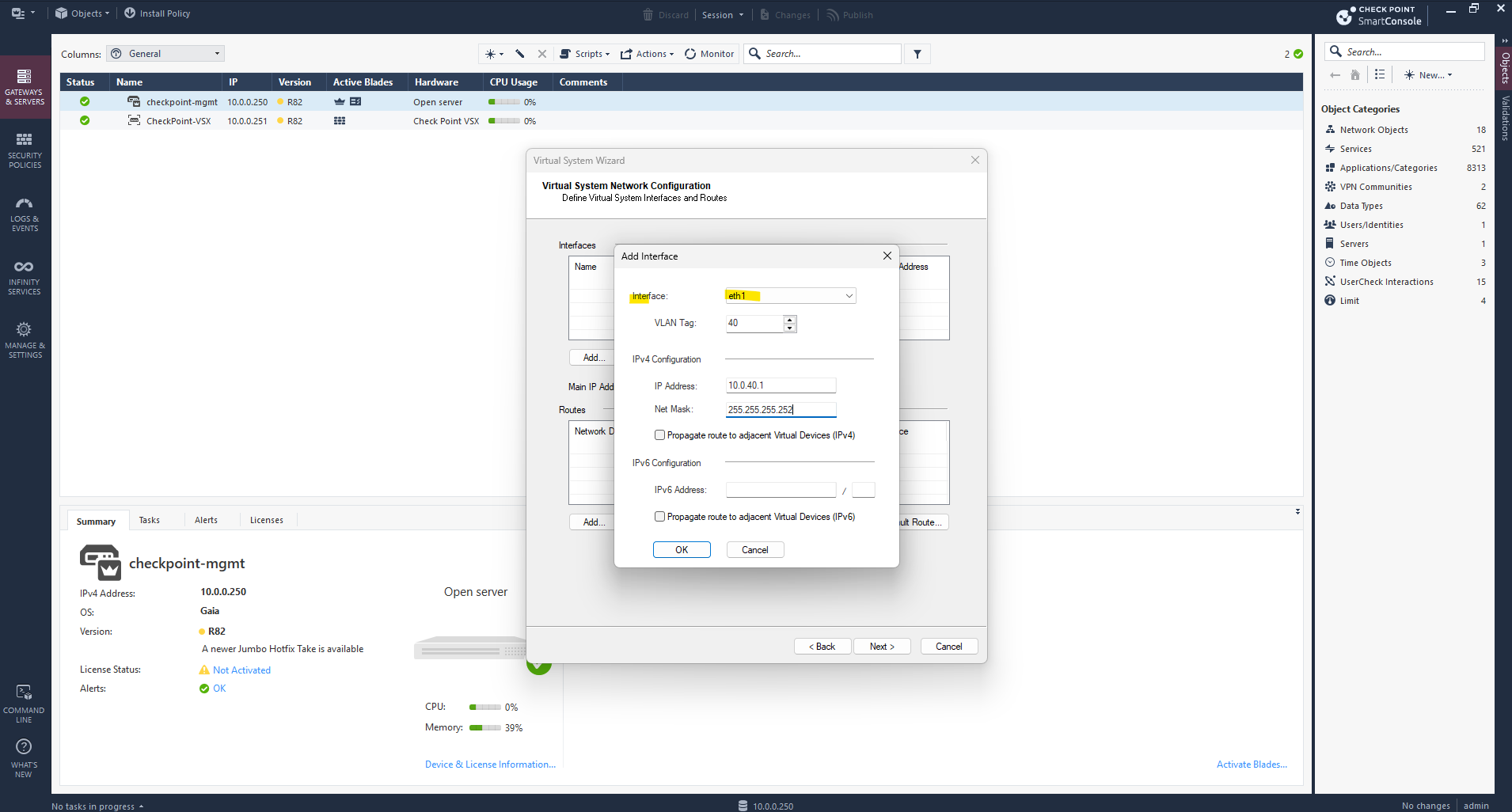
For TenantA, we configure the VSX interface eth1 (Tenant Trunk) with VLAN tag 40 and IP address 10.0.40.1/30, connecting it to the NSX Tier-0 VRF at 10.0.40.2.
Next, we select Add → Leads to Virtual Switch instead of Regular to connect TenantA’s Virtual System to our previously created VSW-Upstream, providing Layer 2 connectivity toward the upstream pfSense router for north-south connectivity.
We select VSW-Upstream and assign the IP address 10.0.0.252/24 to TenantA’s upstream interface, connecting the Virtual System to our existing VLAN 10 network and pfSense router at 10.0.0.1.
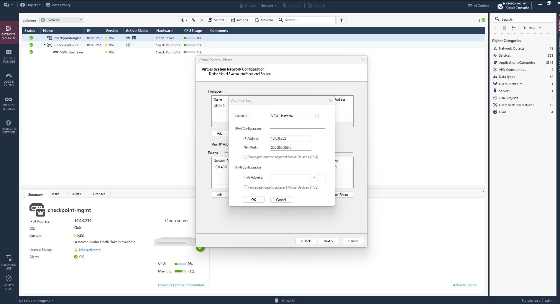
Both interfaces are now configured for TenantA:
eth1.40(10.0.40.1/30) connects to the NSX Tier-0 VRF, whilewrp-new0(10.0.0.252/24) connects to VSW-Upstream for north-south connectivity.Next, we add a default route via 10.0.0.1 to route north-south traffic toward our existing pfSense router.
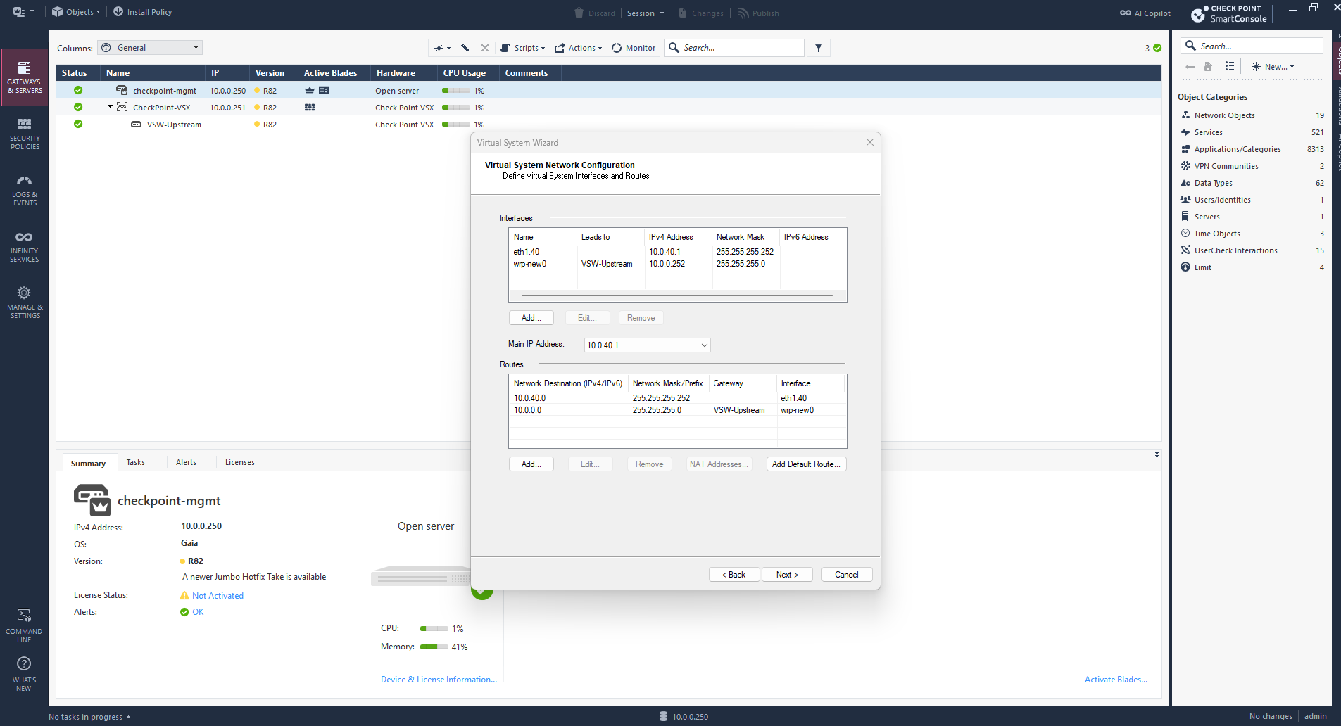
Next, we add a default route (0.0.0.0/0) with 10.0.0.1 as the next-hop gateway, directing TenantA’s north-south traffic through VSW-Upstream toward my existing pfSense router.
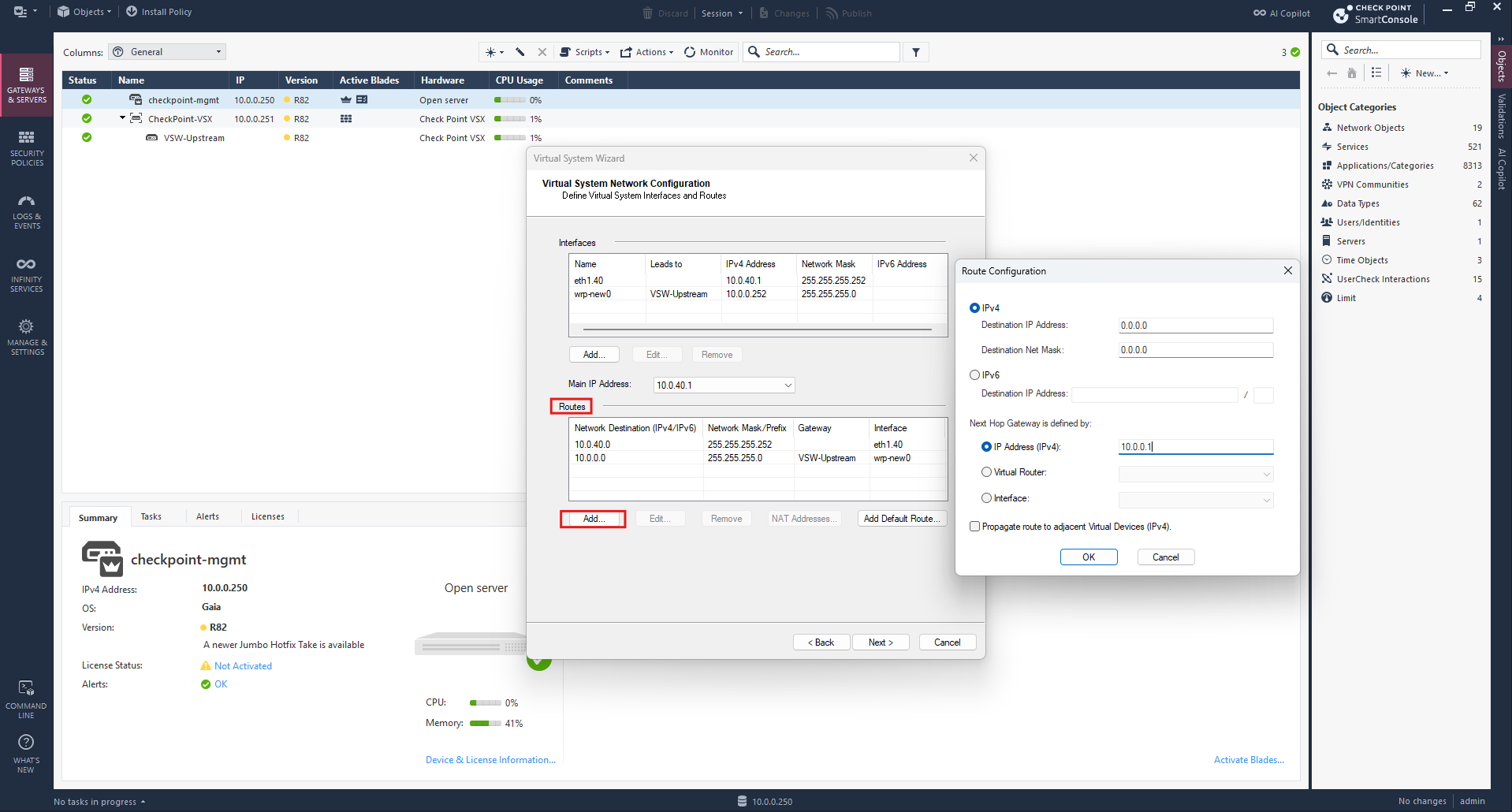
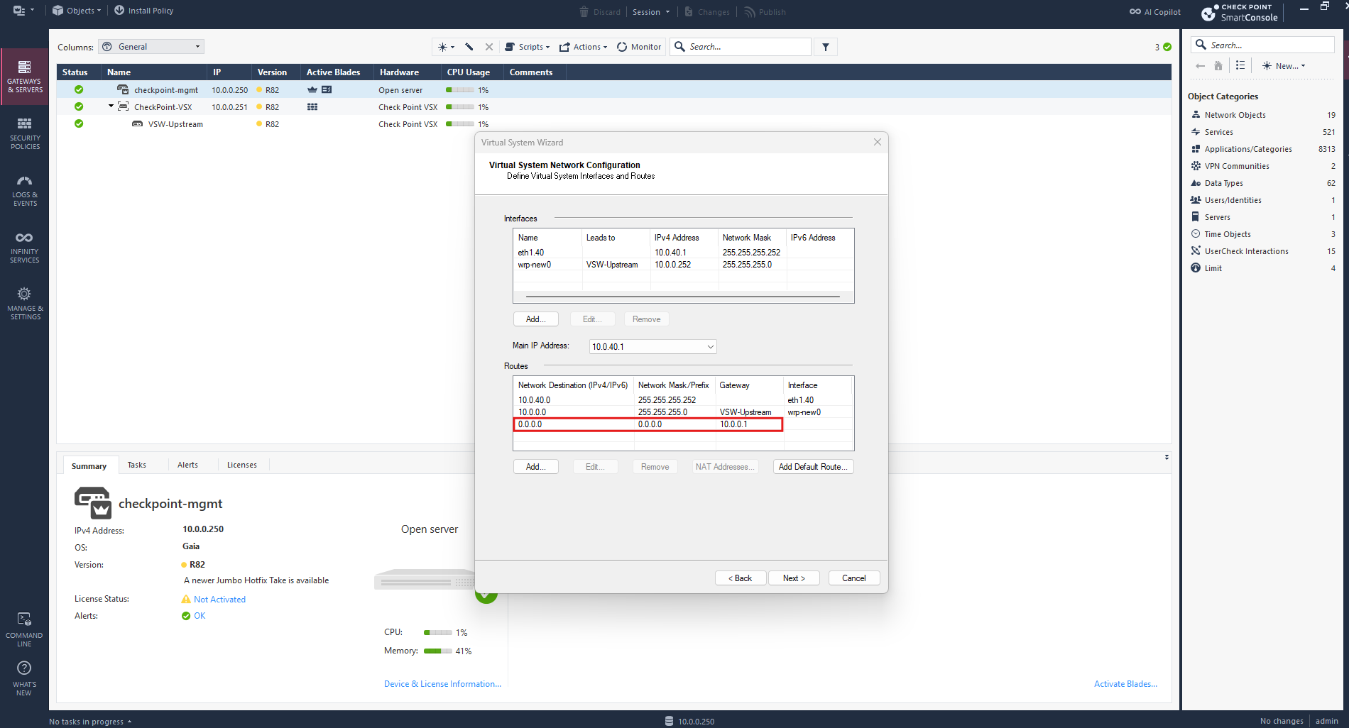
With the network interfaces and routing configured, we click Finish to create our first Virtual System, VS-TenantA, on the Check Point VSX Gateway.
This Virtual System will act as an independent firewall and router for TenantA.
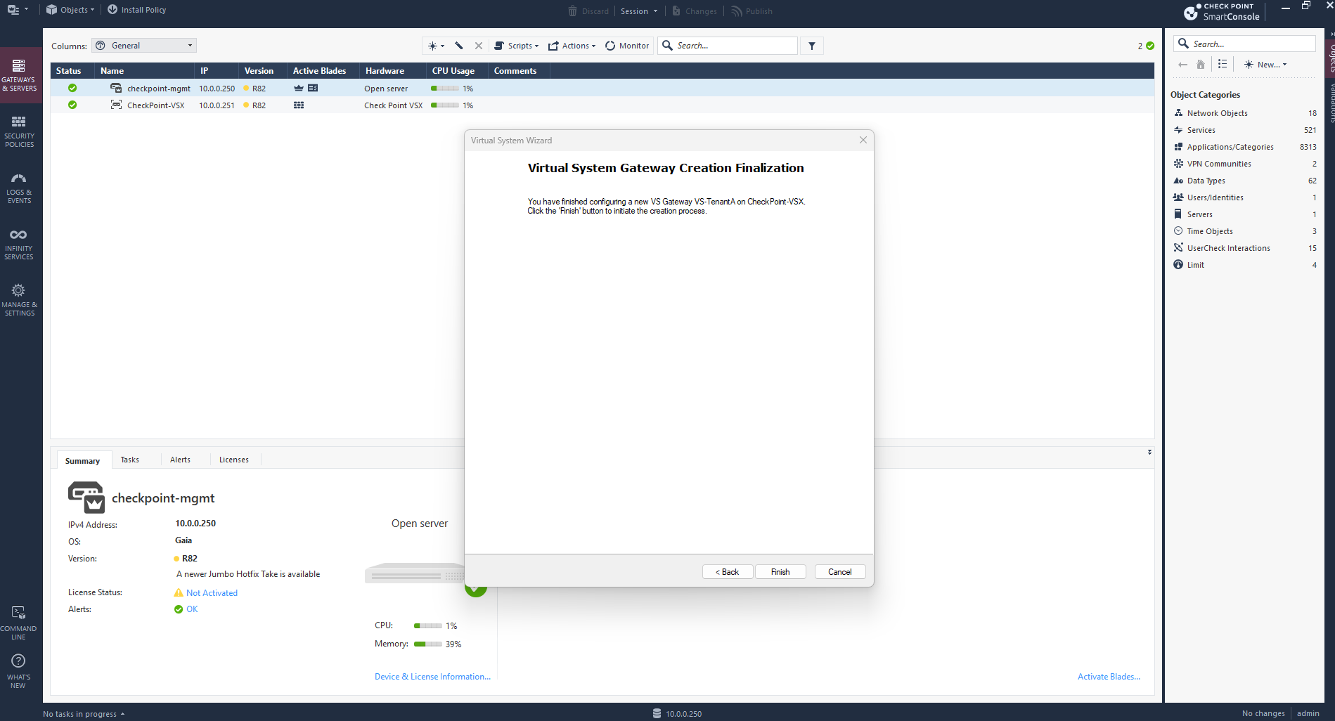
SmartConsole now displays our first Virtual System, VS-TenantA, under the Check Point VSX Gateway.
The wizard provisions the Virtual System with its dedicated interfaces and routing configuration.
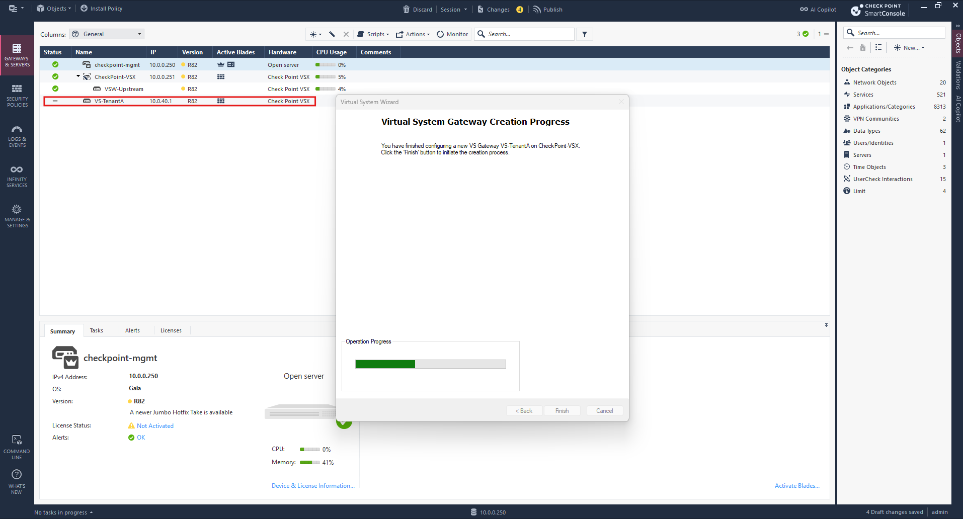
Our first Virtual System, VS-TenantA, has been created successfully. We can now launch the wizard again to configure VS-TenantB, providing a separate firewall and routing instance for our second NSX tenant.
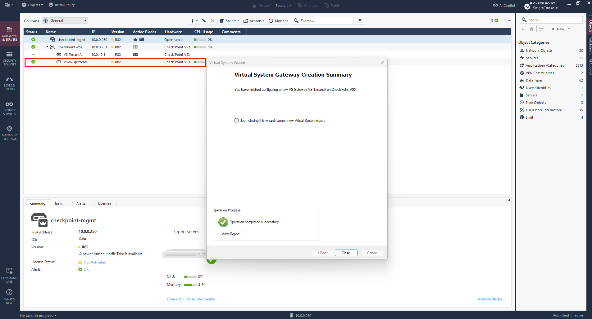
Next, we create our second Virtual System, VS-TenantB, on the same VSX Gateway. Like VS-TenantA, it will operate as an independent firewall and router, maintaining a separate routing and security context for TenantB.
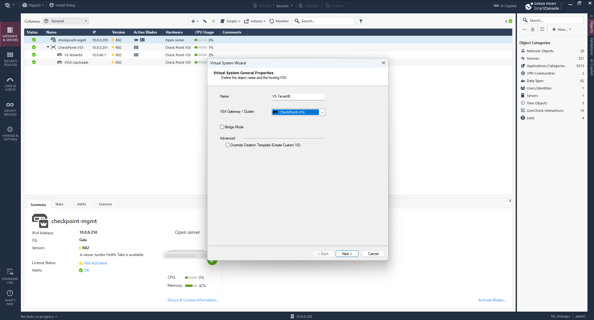
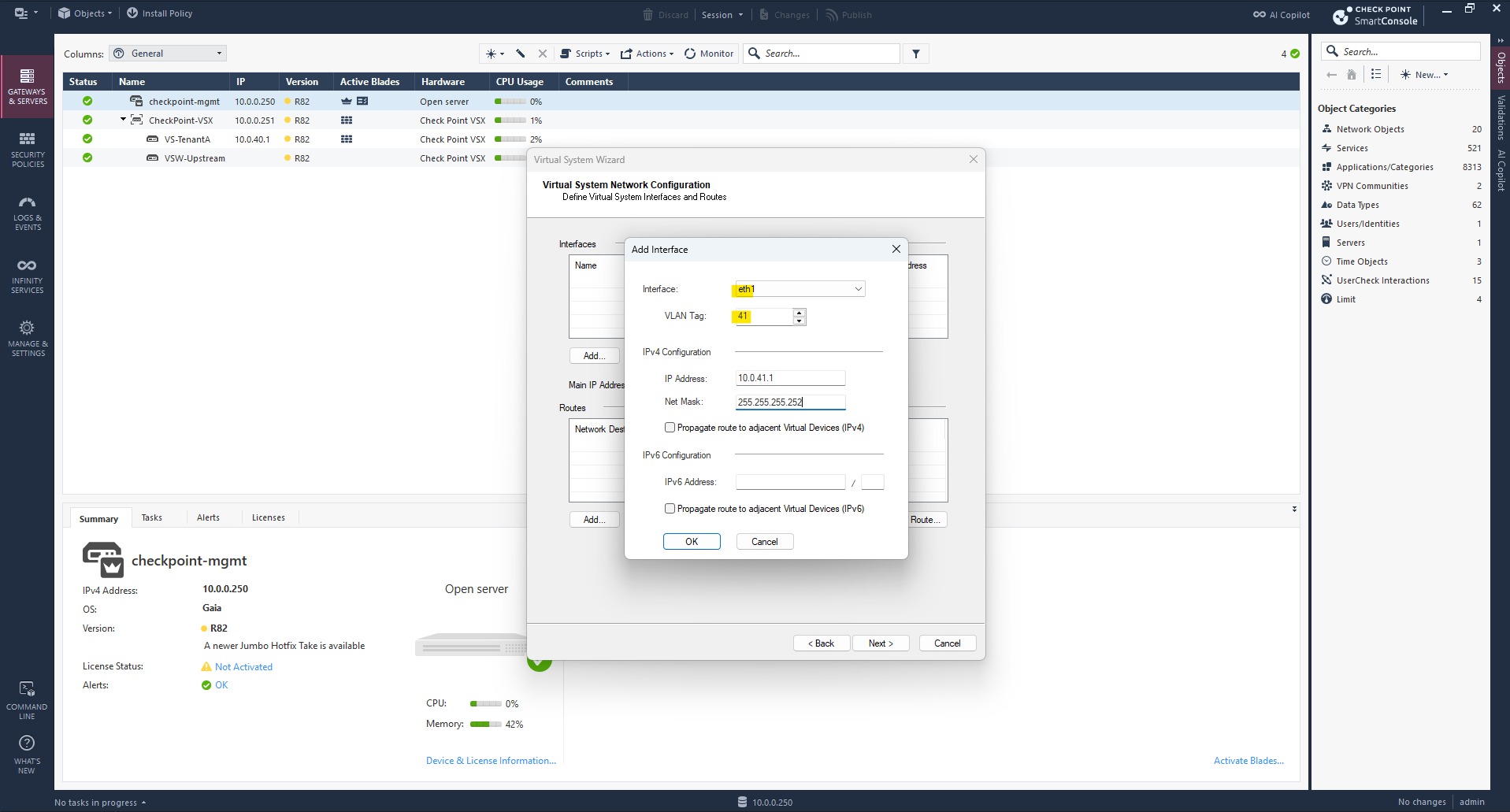
For VS-TenantB, we configure the tenant-facing interface eth1 with VLAN 41 and IP address 10.0.41.1/30.
This connects our second Virtual System to the dedicated NSX Tier-0 VRF uplink for TenantB, independently of TenantA.
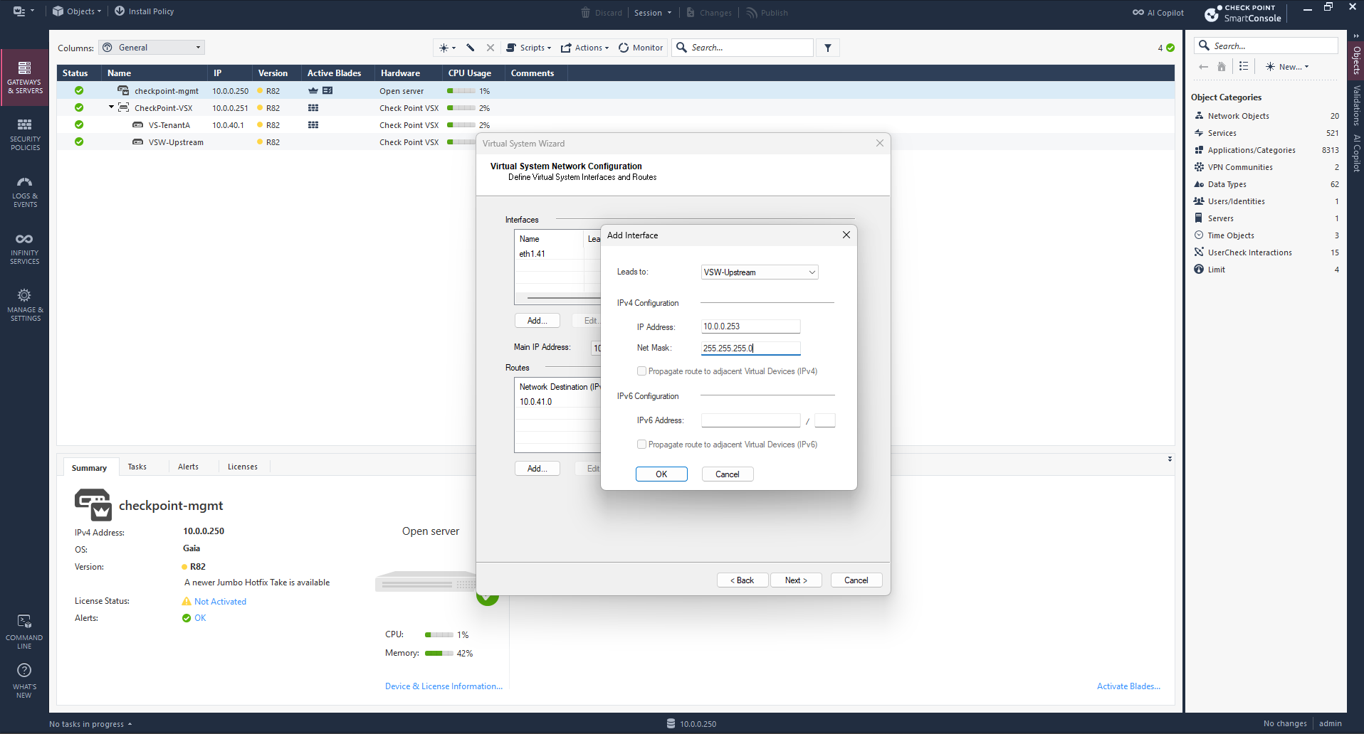
For TenantB, we connect its upstream interface to the same VSW-Upstream and assign 10.0.0.253/24.
Both Virtual Systems share the same Layer 2 upstream network while maintaining independent routing tables and firewall policies.
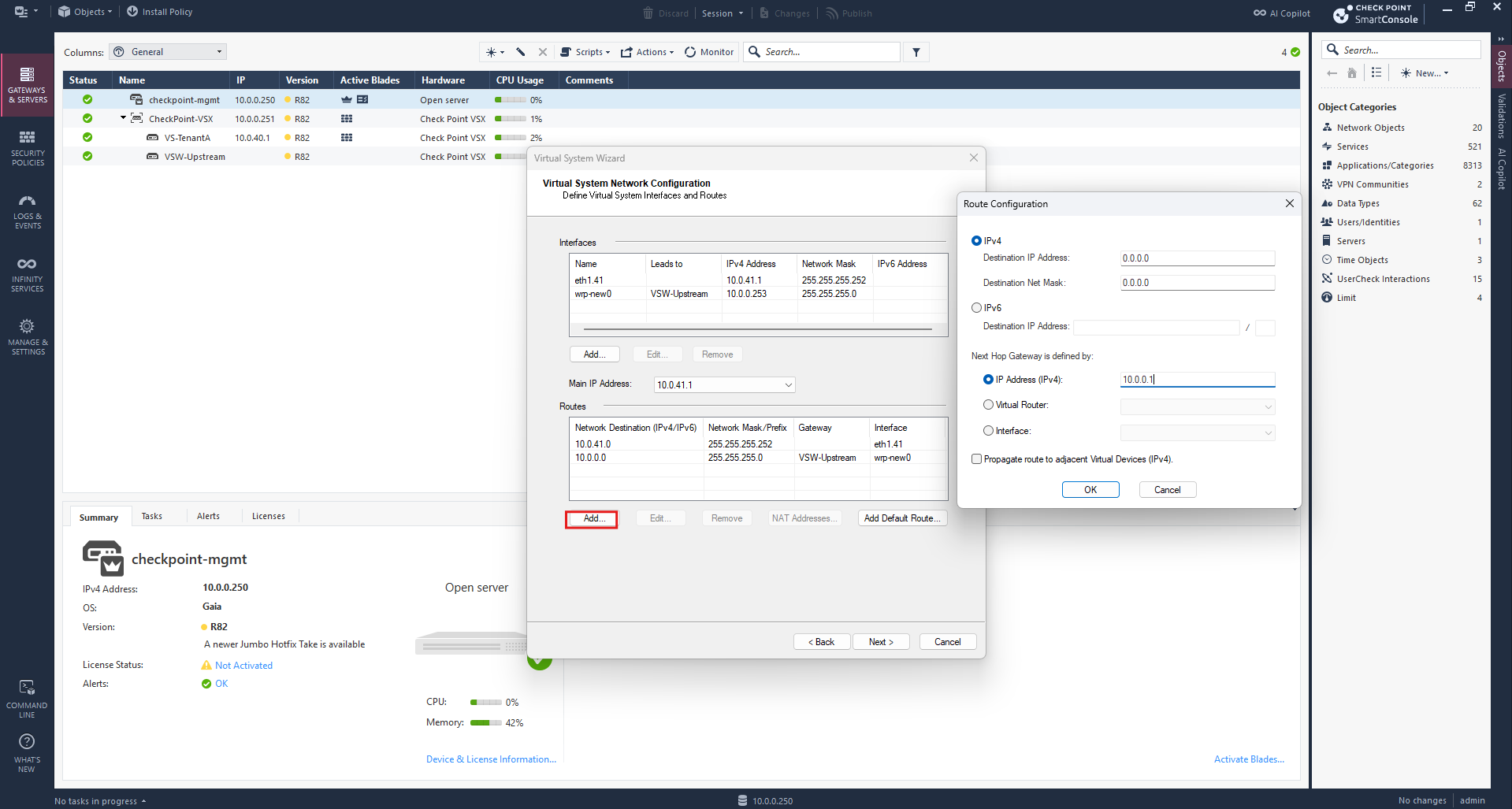
Finally, we configure the same default route (0.0.0.0/0) via 10.0.0.1 for TenantB, directing its north-south traffic through VSW-Upstream toward my existing pfSense router.
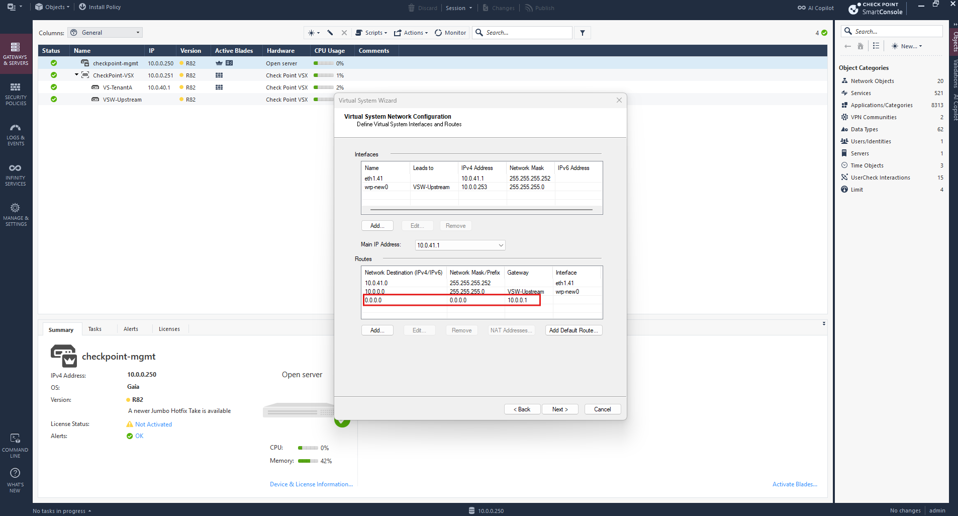
Both Virtual Systems (VS-TenantA and VS-TenantB) and the shared Virtual Switch (VSW-Upstream) have now been successfully created and are listed under our Check Point VSX Gateway in SmartConsole, with all components showing green status indicators. Each Virtual System has its own independent routing and firewall context, allowing us to handle overlapping tenant networks while sharing the upstream Layer 2 connectivity.
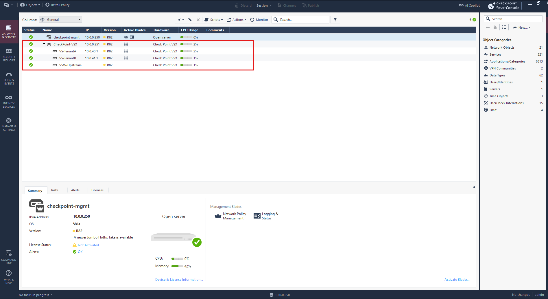
With both Virtual Systems and the shared Virtual Switch successfully created, our basic VSX network topology is now in place.
Next, we configure the firewall policies and NAT rules, install the policies, and verify north-south connectivity from both NSX tenants through the Check Point VSX Gateway toward pfSense and the Internet.
Configure Firewall Policies and NAT for Both Virtual Systems
With both Virtual Systems and the shared Virtual Switch configured, we can now define the firewall policies and NAT rules required for north-south connectivity.
In Check Point SmartConsole, navigate to Security Policies → Access Control → Policy. By default, the Standard policy package contains only a Cleanup rule that drops all traffic. We will configure the necessary access rules and source NAT for our two tenants, allowing their overlapping IPv4 networks to communicate with external networks through the VSX Gateway and our existing pfSense router.
Create Separate Security Policy Packages
Before configuring the firewall and NAT rules, we create two separate Security Policy Packages, one for VS-TenantA and another for VS-TenantB. Each package will be installed on its corresponding Virtual System, allowing us to manage the security policies of both tenants independently despite their overlapping IPv4 networks.
To create separate firewall policies for our two tenants, open the SmartConsole main menu → Manage policies and layers.
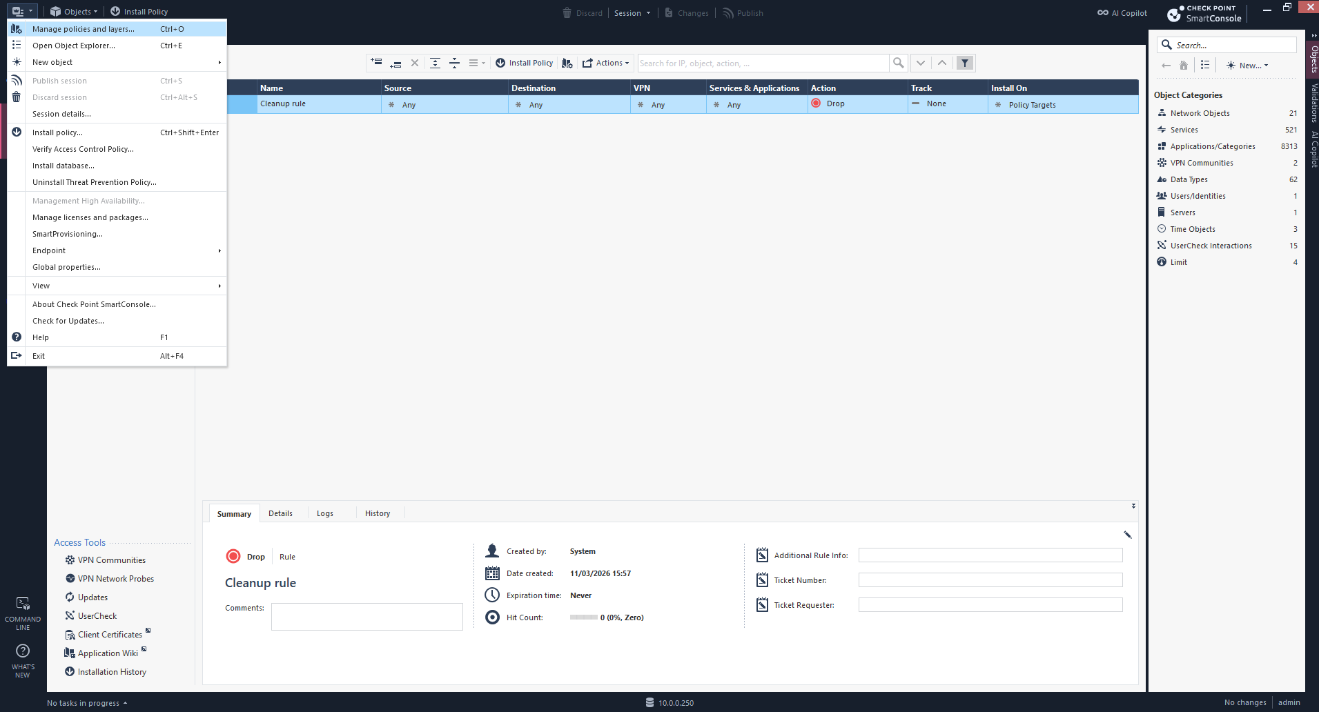
Here, we can create dedicated policy packages for VS-TenantA and VS-TenantB, keeping their security configurations independent.
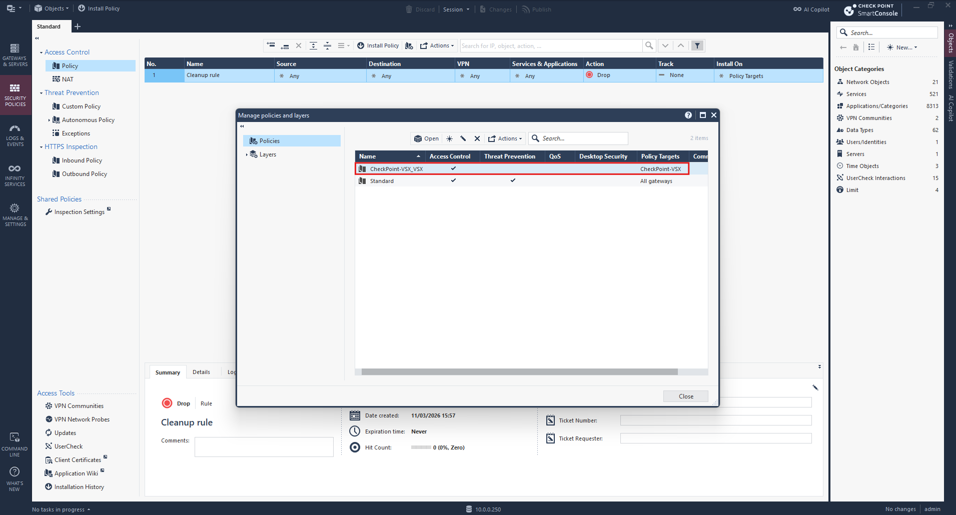
Opening Manage Policies and Layers reveals two existing policy packages: the default Standard package and CheckPoint-VSX_VSX, which was automatically created during VSX Gateway provisioning and targets our CheckPoint-VSX Gateway.
For our multi-tenant configuration, we create two additional policy packages,
TenantA-PolicyandTenantB-Policy, to manage the firewall rules for each Virtual System independently.
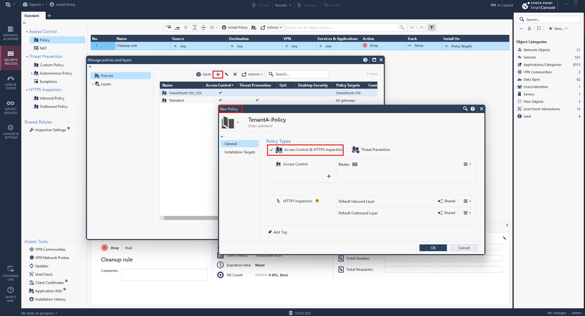
We create the first policy package named TenantA-Policy, enabling Access Control while leaving Threat Prevention disabled for our initial connectivity tests.
Under Installation Targets, we select Specific gateways and assign VS-TenantA (10.0.40.1) as the installation target.
This ensures that the policy package applies exclusively to TenantA’s Virtual System, keeping its firewall configuration independent from TenantB.
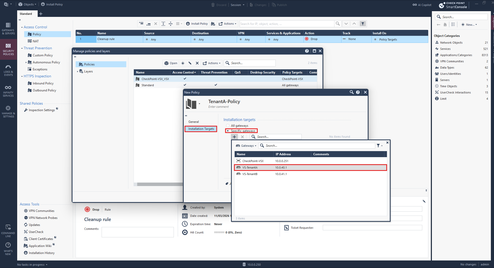
We repeat the same procedure for TenantB, creating a separate policy package named TenantB-Policy and assigning VS-TenantB (10.0.41.1) as its installation target.
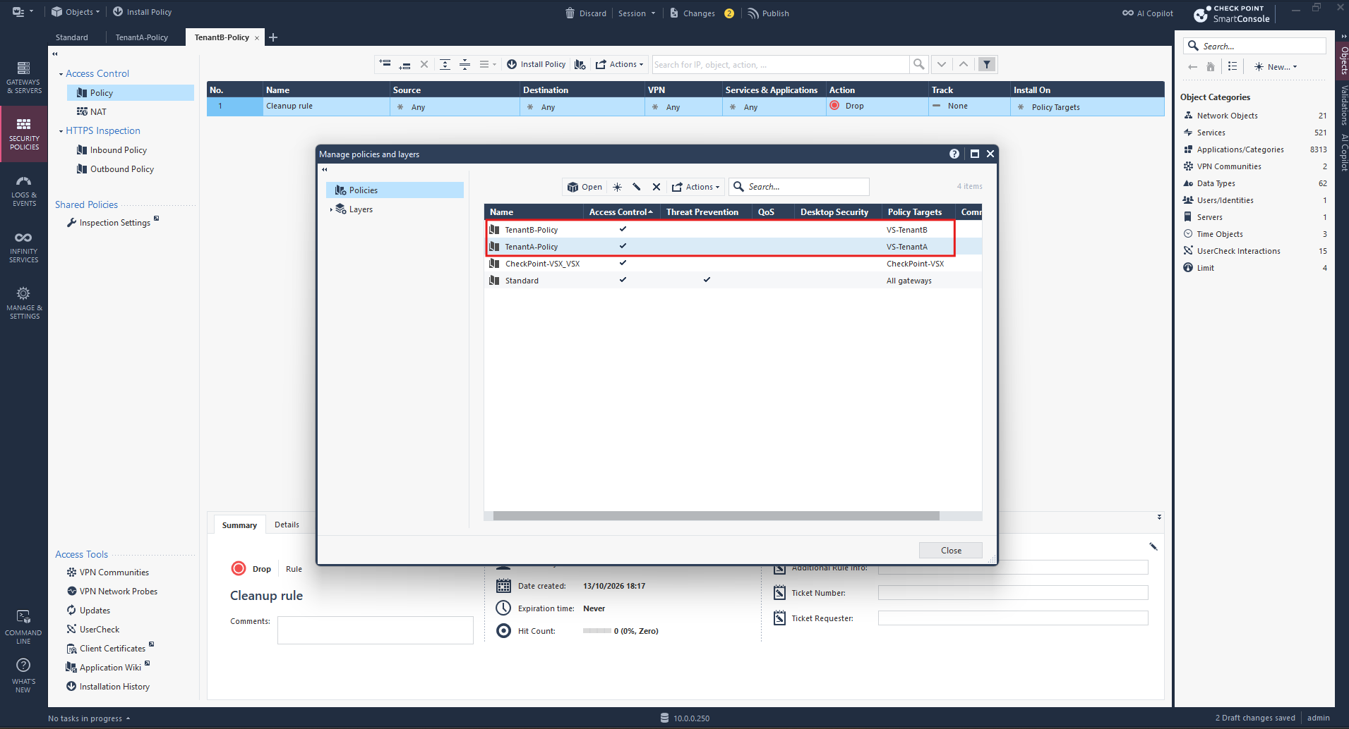
Both Virtual Systems now have independent policy packages, allowing us to configure and manage their firewall rules separately.
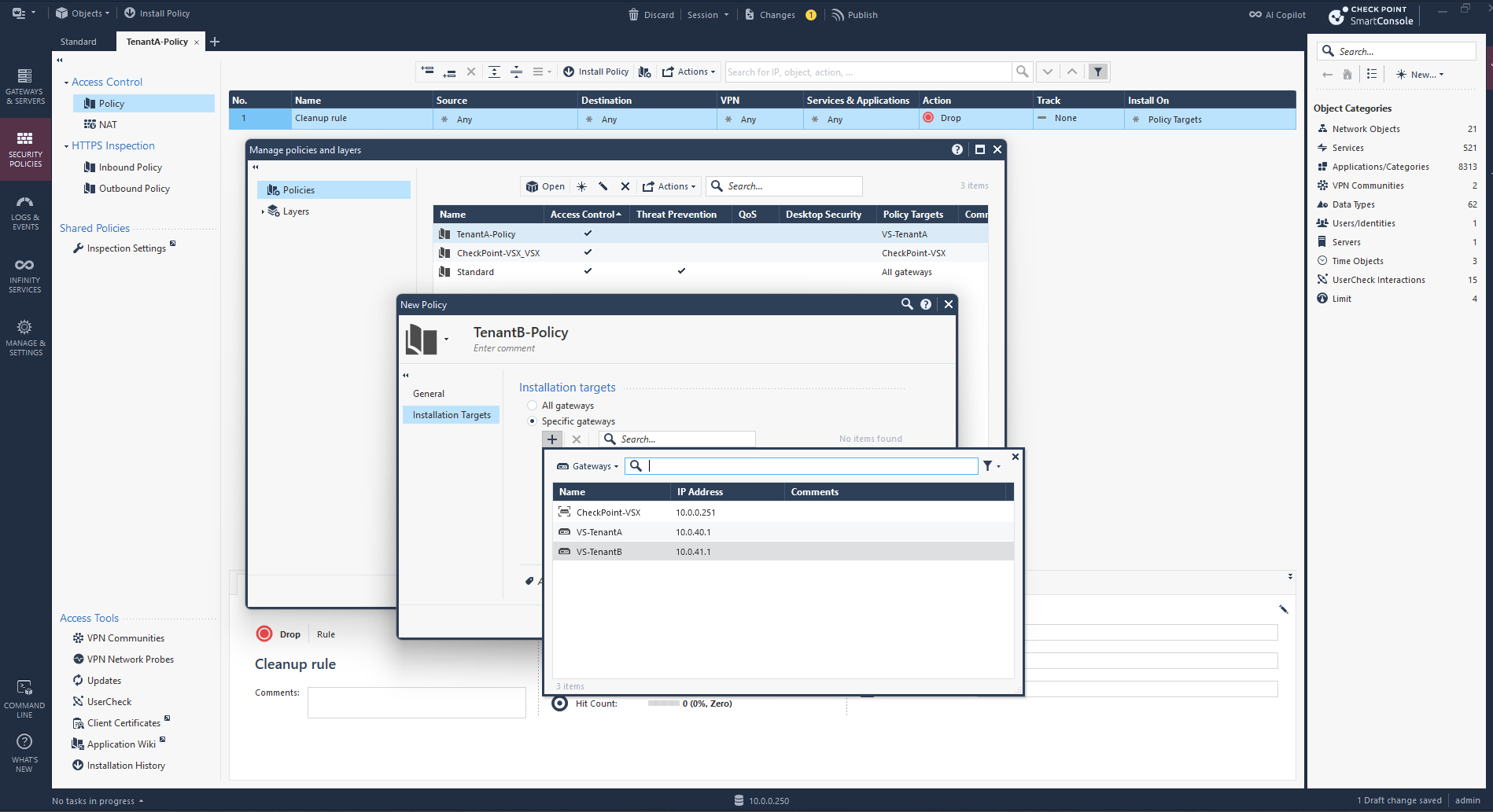
Both tenant-specific policy packages are now configured, each with its own Virtual System as the installation target.
This allows us to manage and install firewall policies independently for TenantA and TenantB, even though both Virtual Systems run on the same physical VSX Gateway.
Next, we configure the Access Control rules for each tenant-specific policy package. For our initial connectivity tests, we allow outbound traffic and enable logging, while retaining the default Cleanup rule to drop traffic that does not match an explicit rule.
Configure Access Control Rules for TenantA
Before configuring the Access Control rules, we first need to select the correct tenant-specific policy package in SmartConsole, TenantA-Policy or TenantB-Policy.
We begin by configuring the Access Control policy for TenantA. In SmartConsole, we open TenantB-Policy → Access Control → Policy and add a rule to permit outbound traffic through VS-TenantB, while keeping the default Cleanup rule to drop all other traffic.
We can reopen both policy packages directly from SmartConsole:
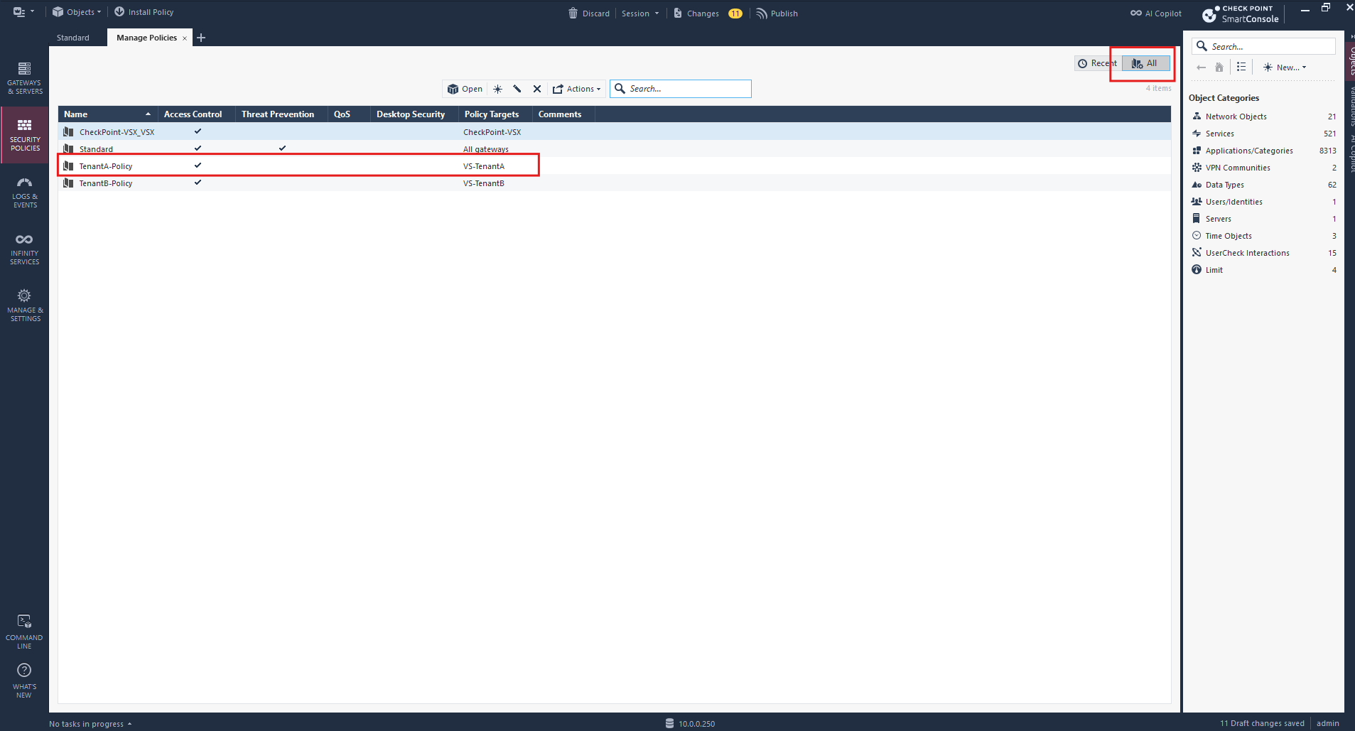
Click the + icon next to the Standard tab at the top left.
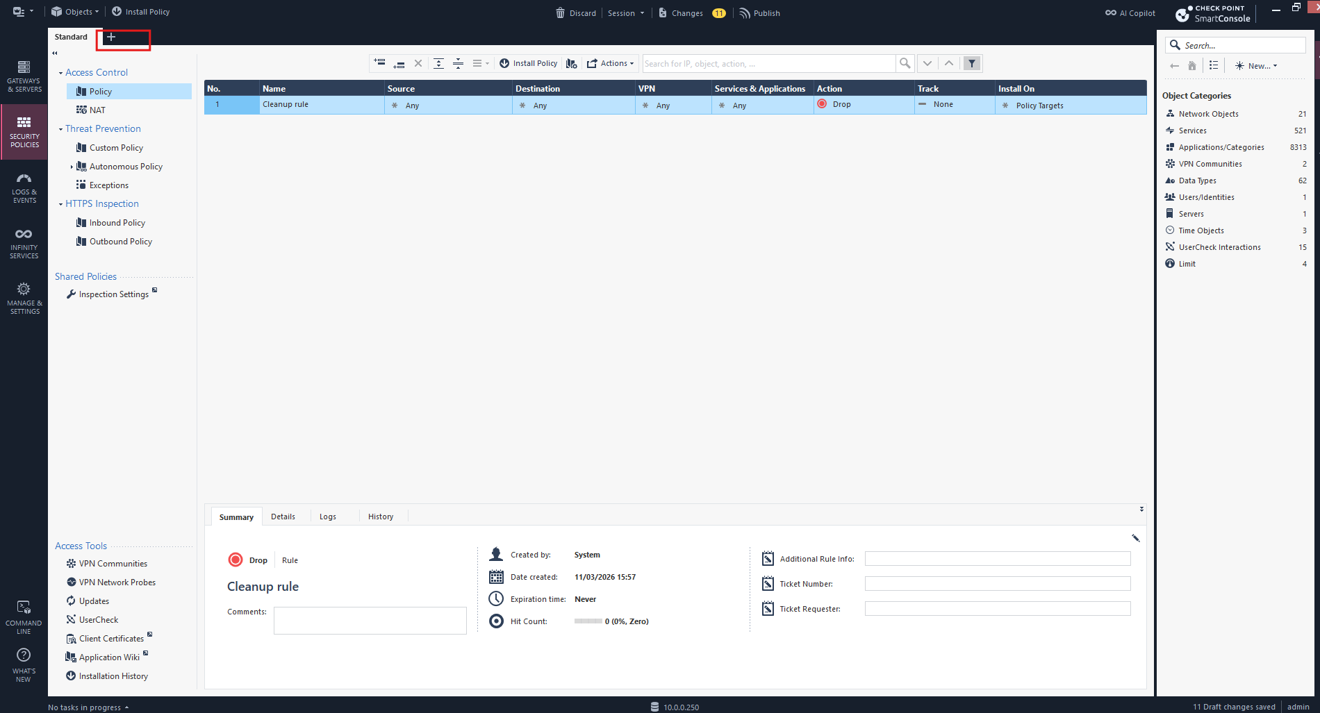
Click the All button in the upper-right corner, next to Recent. This displays all available policy packages. Select TenantA-Policy or TenantB-Policy to open it.
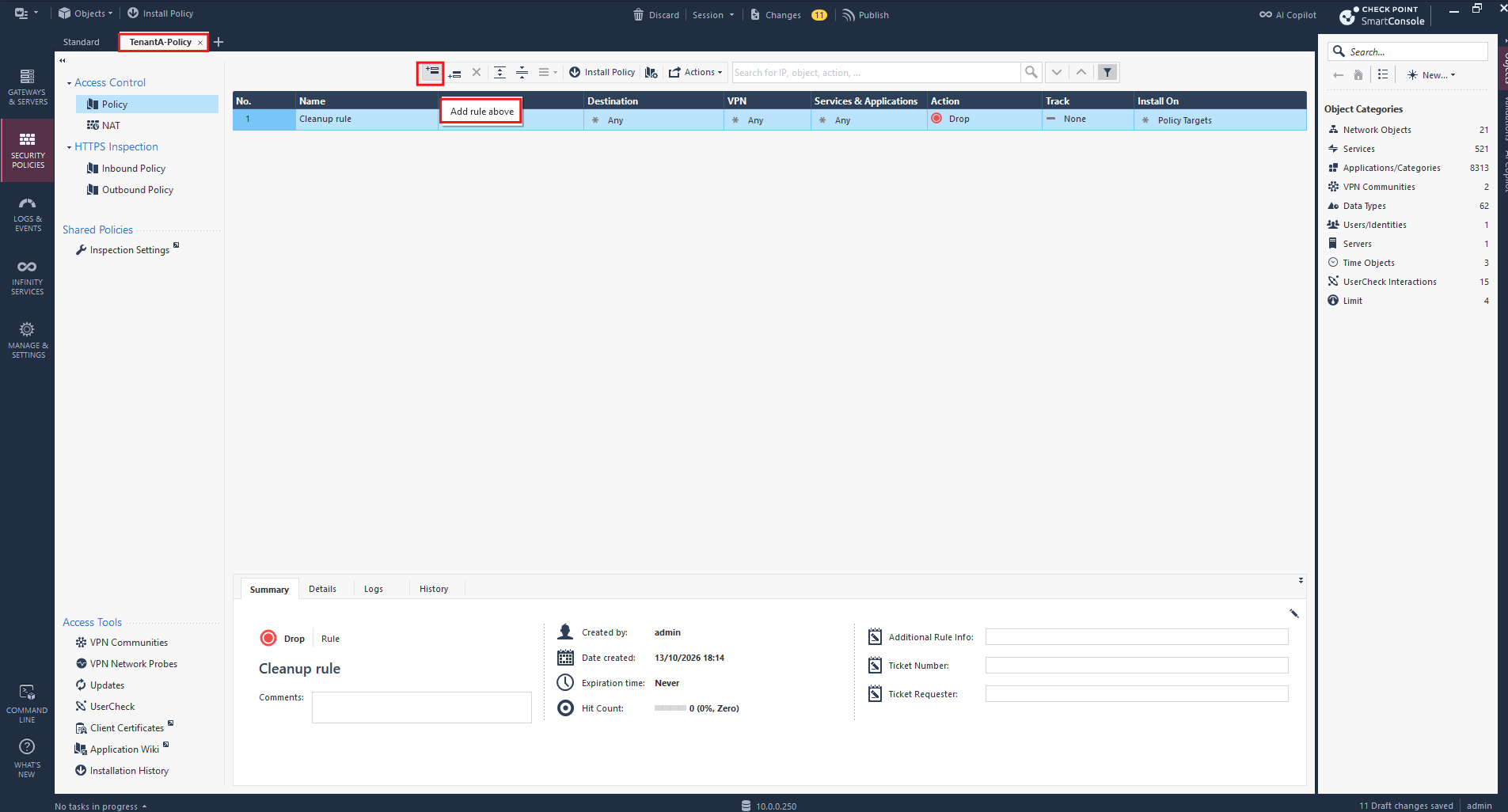
| Field | Value |
|---|---|
| Name | TenantA-Outbound |
| Source | 192.168.100.0/24 |
| Destination | Any |
| VPN | Any |
| Services & Applications | Any |
| Action | Accept |
| Track | Log |
| Install On | VS-TenantA |
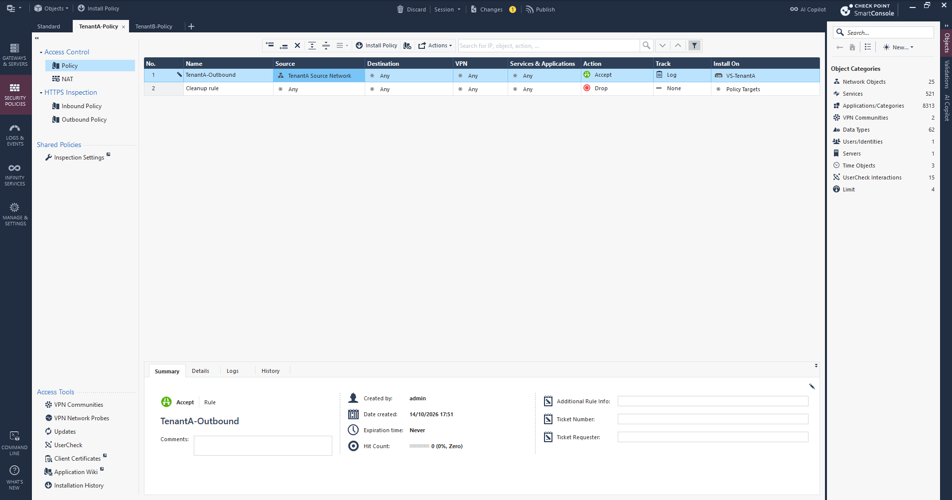
The first Access Control rule for TenantA is now configured. It permits traffic for our initial connectivity tests, enables logging, and applies exclusively to VS-TenantA, while the default Cleanup rule remains in place.
Configure Access Control Rules for TenantB
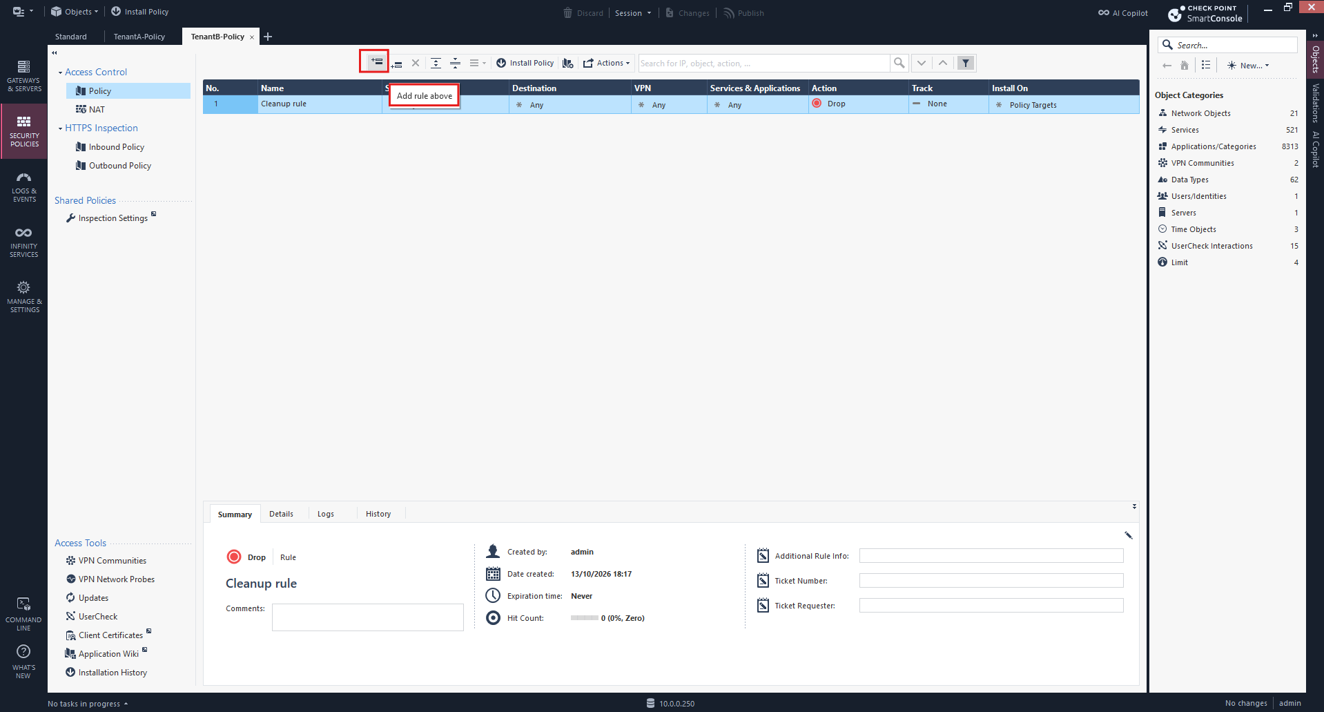
Next we configure the Access Control policy for TenantB. In SmartConsole, we open TenantB-Policy → Access Control → Policy and add a rule to permit outbound traffic through VS-TenantB, while keeping the default Cleanup rule to drop all other traffic.
| Field | Value |
|---|---|
| Name | TenantB-Outbound |
| Source | 192.168.100.0/24 |
| Destination | Any |
| VPN | Any |
| Services & Applications | Any |
| Action | Accept |
| Track | Log |
| Install On | VS-TenantB |
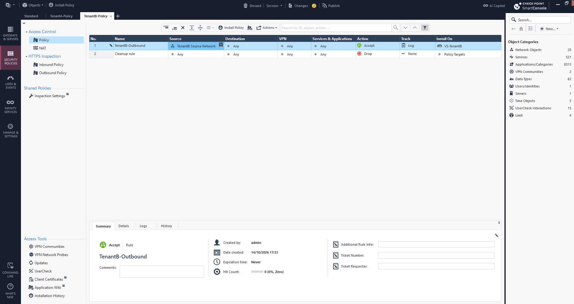
The first Access Control rule for TenantB is now also configured. It permits traffic for our initial connectivity tests, enables logging, and applies exclusively to VS-TenantB, while the default Cleanup rule remains in place.
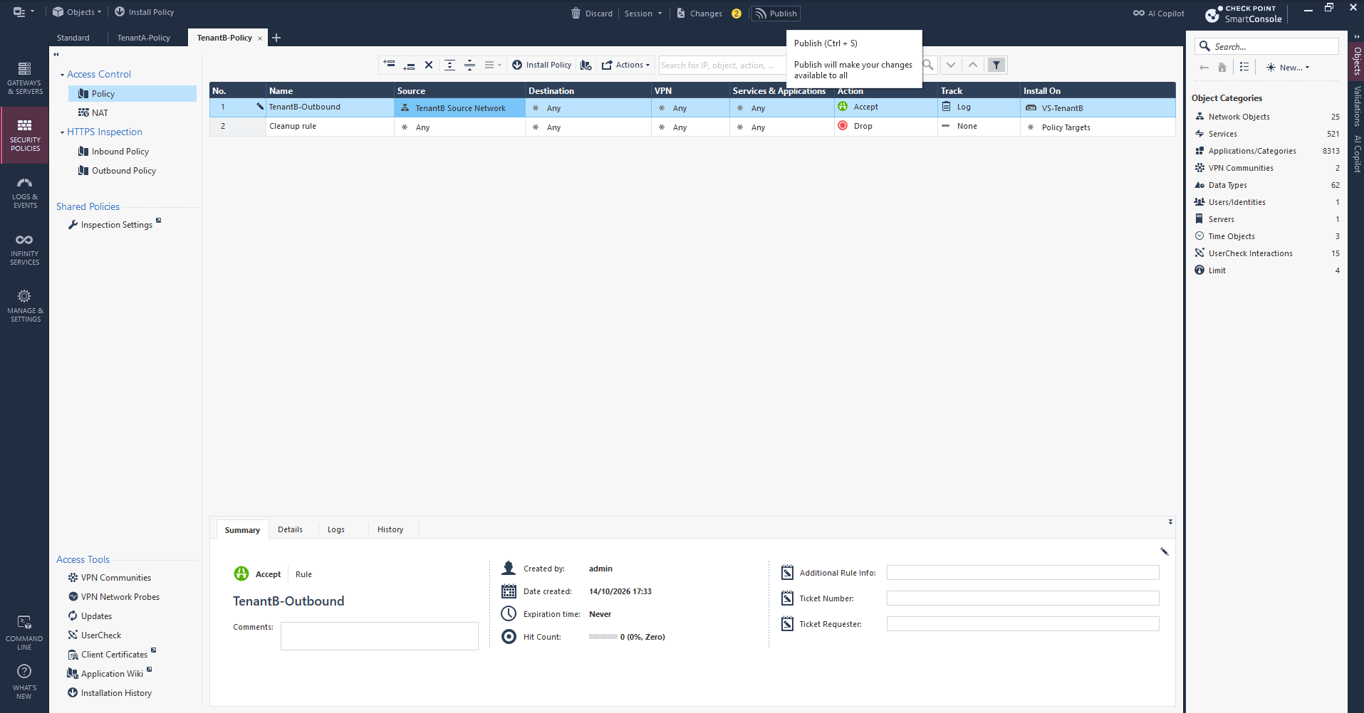
With the Access Control rules configured for both tenants, we click Publish to save our changes to the Security Management Server.
Publishing does not yet activate the firewall rules on the Virtual Systems; this requires a separate Install Policy operation.
Configure Source NAT for TenantA and TenantB
Next, we configure Source NAT for both Virtual Systems. Each tenant uses the same internal IPv4 subnet, 192.168.100.0/24, but VSX maintains separate routing and NAT contexts, allowing both tenants to communicate with external networks independently.
In SmartConsole, we open Security Policies → TenantA-Policy → NAT
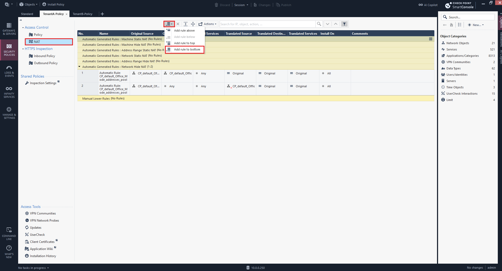
For TenantA, our intended configuration is:
TenantA – Source NAT
| Setting | Value |
|---|---|
| Original Source | 192.168.100.0/24 |
| Original Destination | Any |
| Original Services | Any |
| Translated Source | Hide behind 10.0.0.252 |
| Translated Destination | Original |
| Translated Services | Original |
| Install On | VS-TenantA |
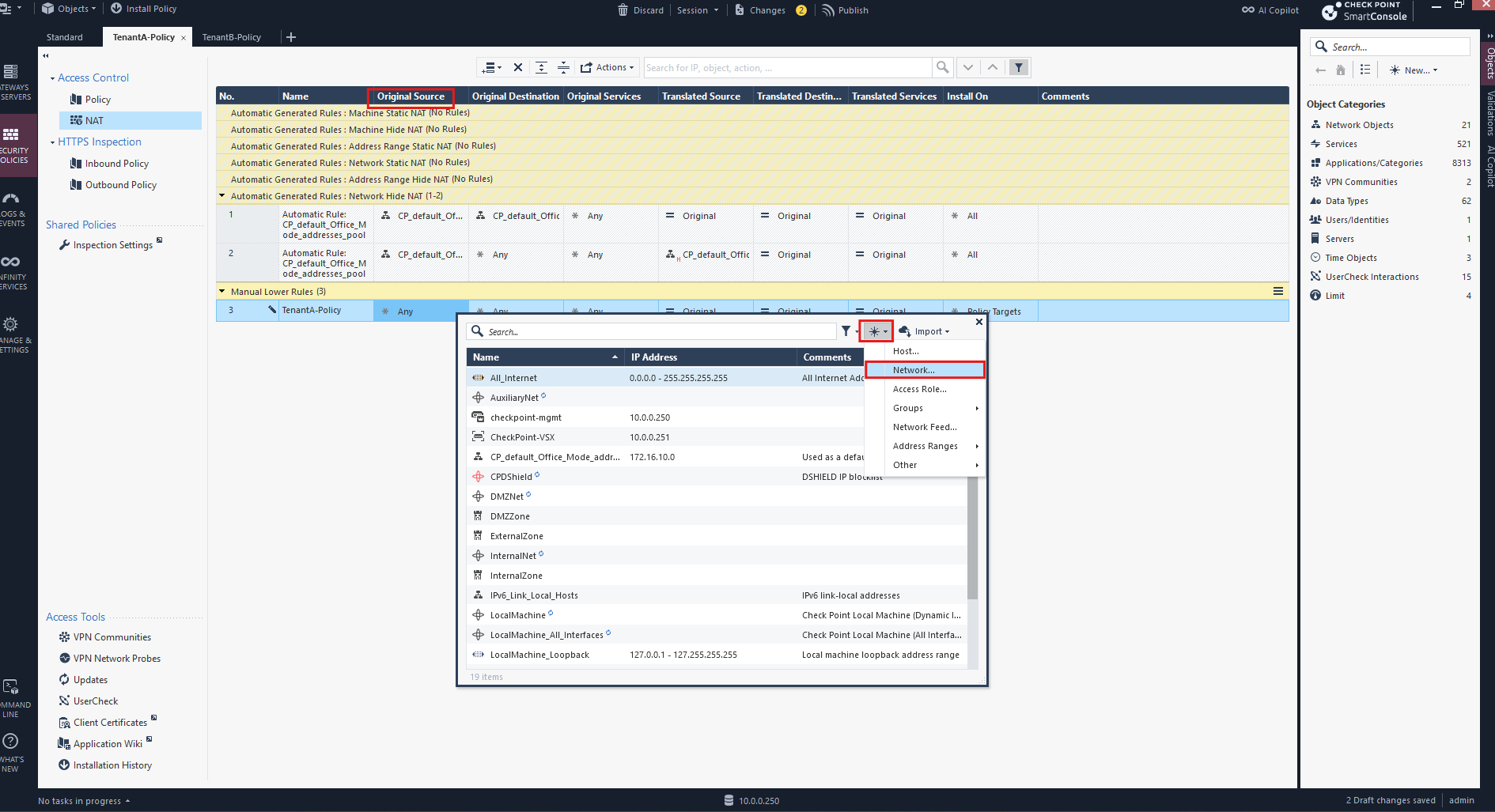
First, we create a network object named TenantA Source Network for the subnet 192.168.100.0/24 and assign it to Original Source in our manual NAT rule. We leave the object’s NAT settings unchanged, as NAT will be configured directly in the policy.
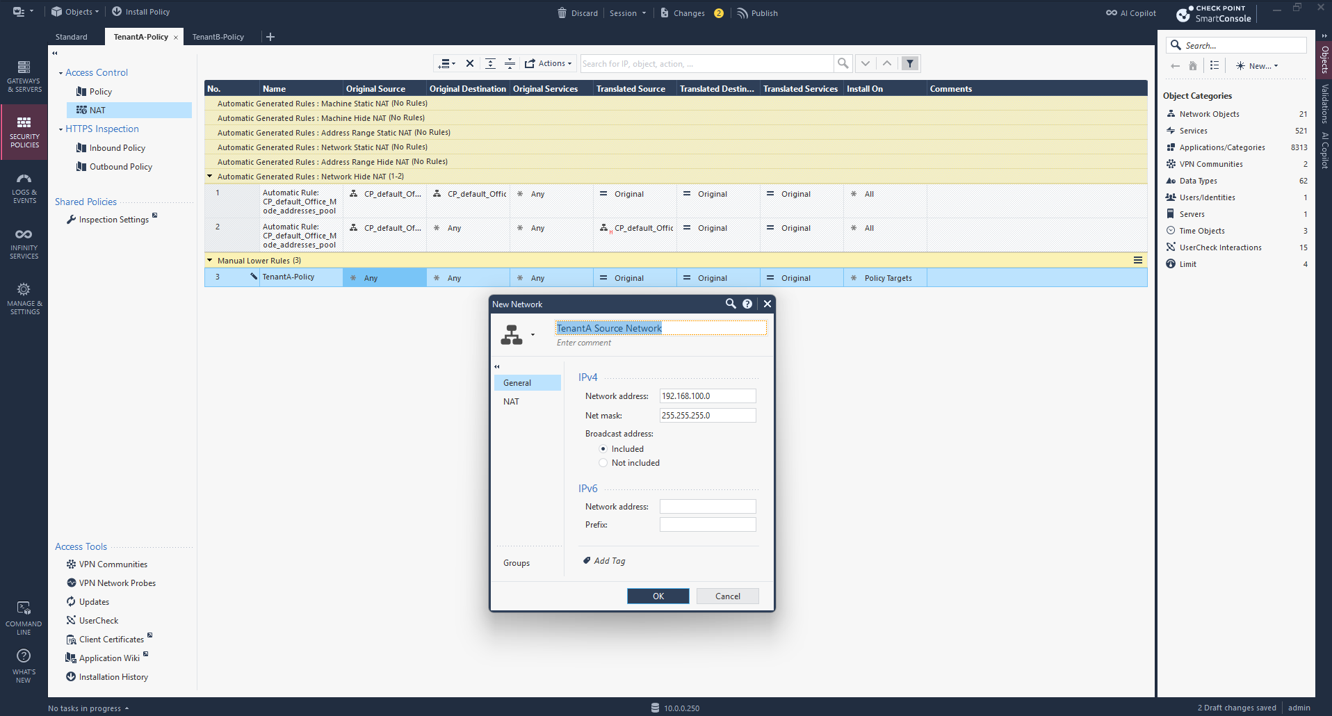
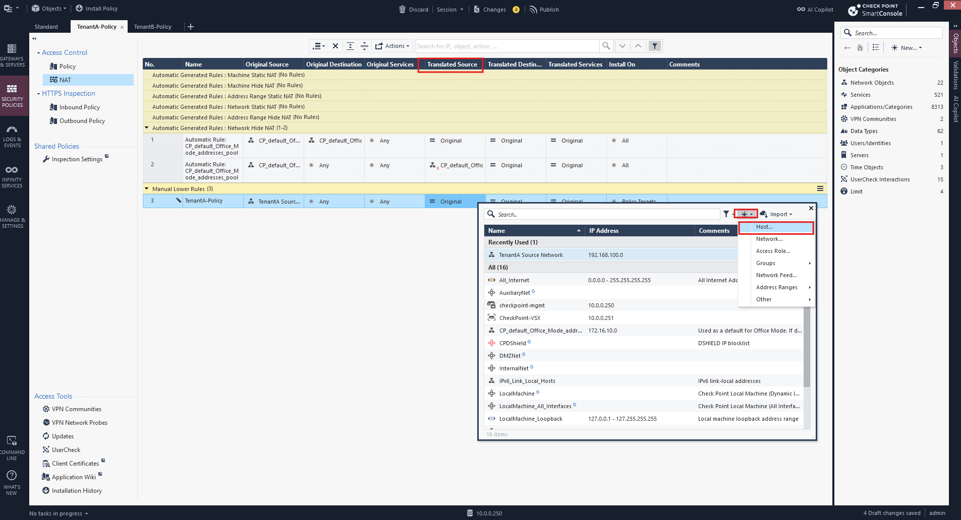
For Translated Source, select New → Host and create a host object.
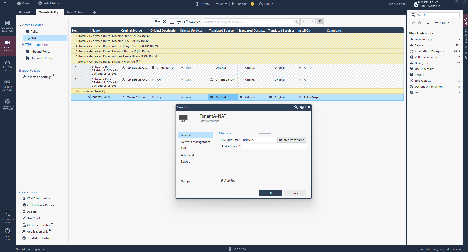
We create a host object named TenantA-NAT with the IP address 10.0.0.252 and assign it as the Translated Source in our manual NAT rule.
This address will be used for Hide NAT, translating TenantA’s internal source addresses for outbound traffic toward pfSense.
For the Translated Source, we select the corresponding NAT host object and set NAT Method → Hide using the context menu.
The small indicator beneath the object changes from S (Static) to H (Hide), indicating that Hide NAT is configured.
Static NAT (S) provides a one-to-one mapping between original and translated IP addresses, typically used for publishing servers.
Hide NAT (H) allows multiple internal IP addresses to share a single translated IP address by using port translation, making it ideal for outbound Internet access.
In pfSense, Outbound NAT can operate in Automatic, Hybrid, or Manual mode. Check Point Hide NAT is essentially what pfSense does with its standard Outbound NAT rules, translating multiple internal clients behind a single external address.
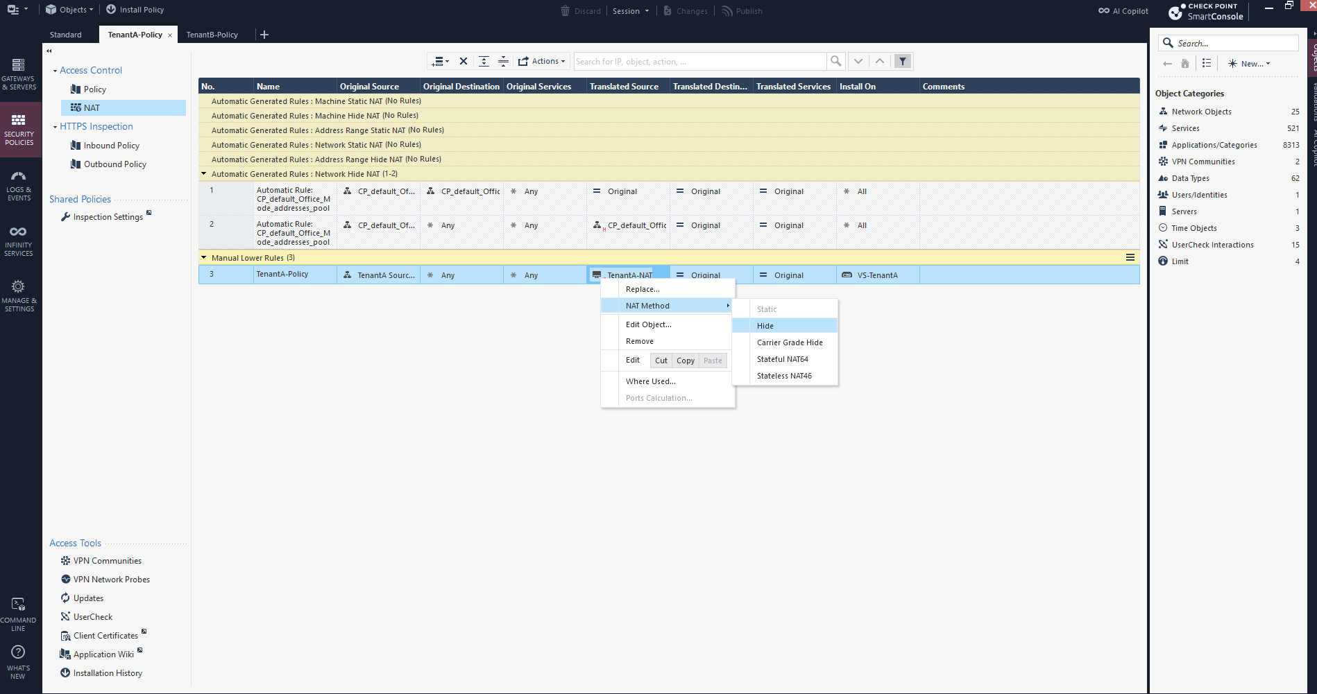
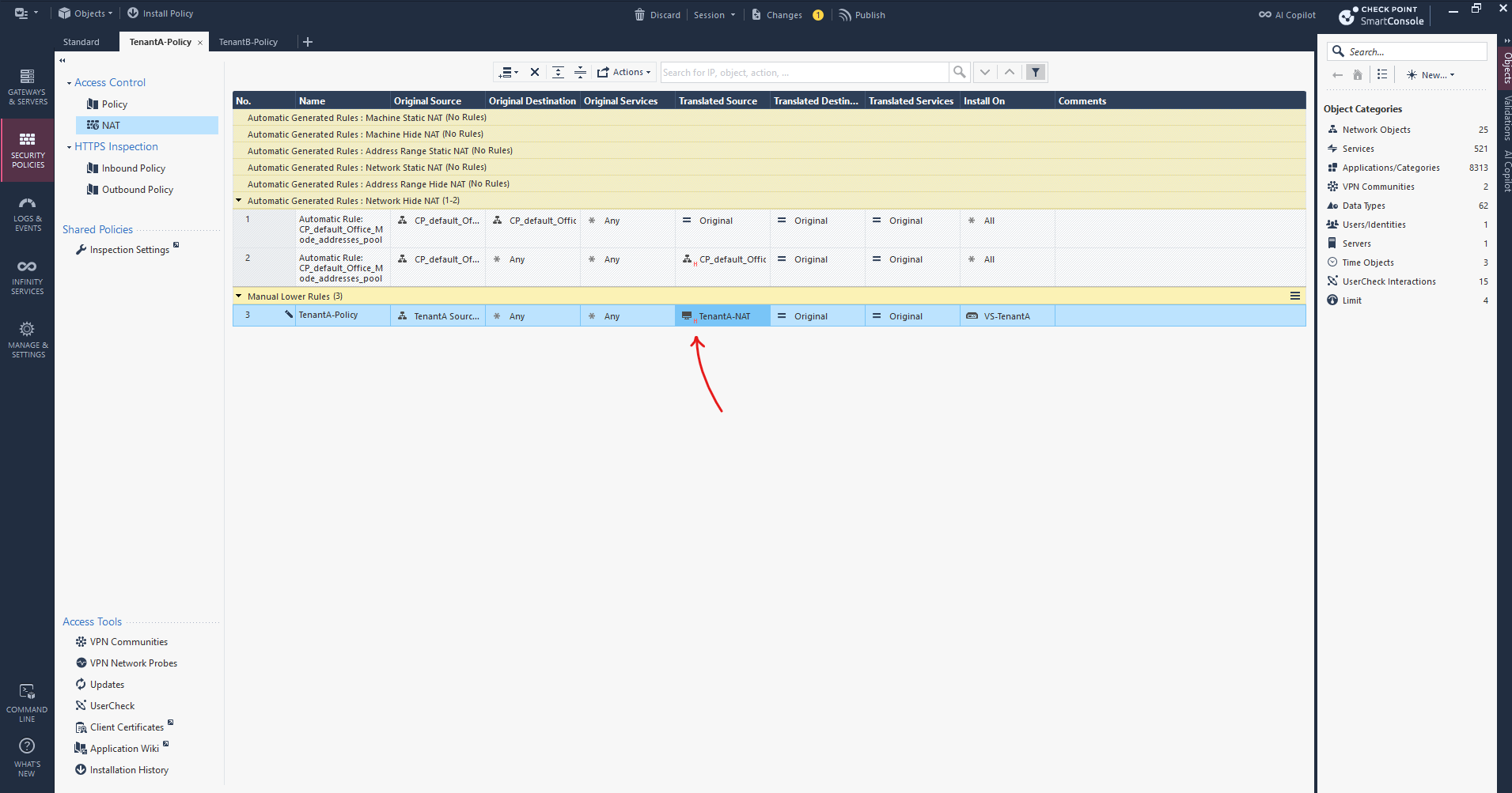
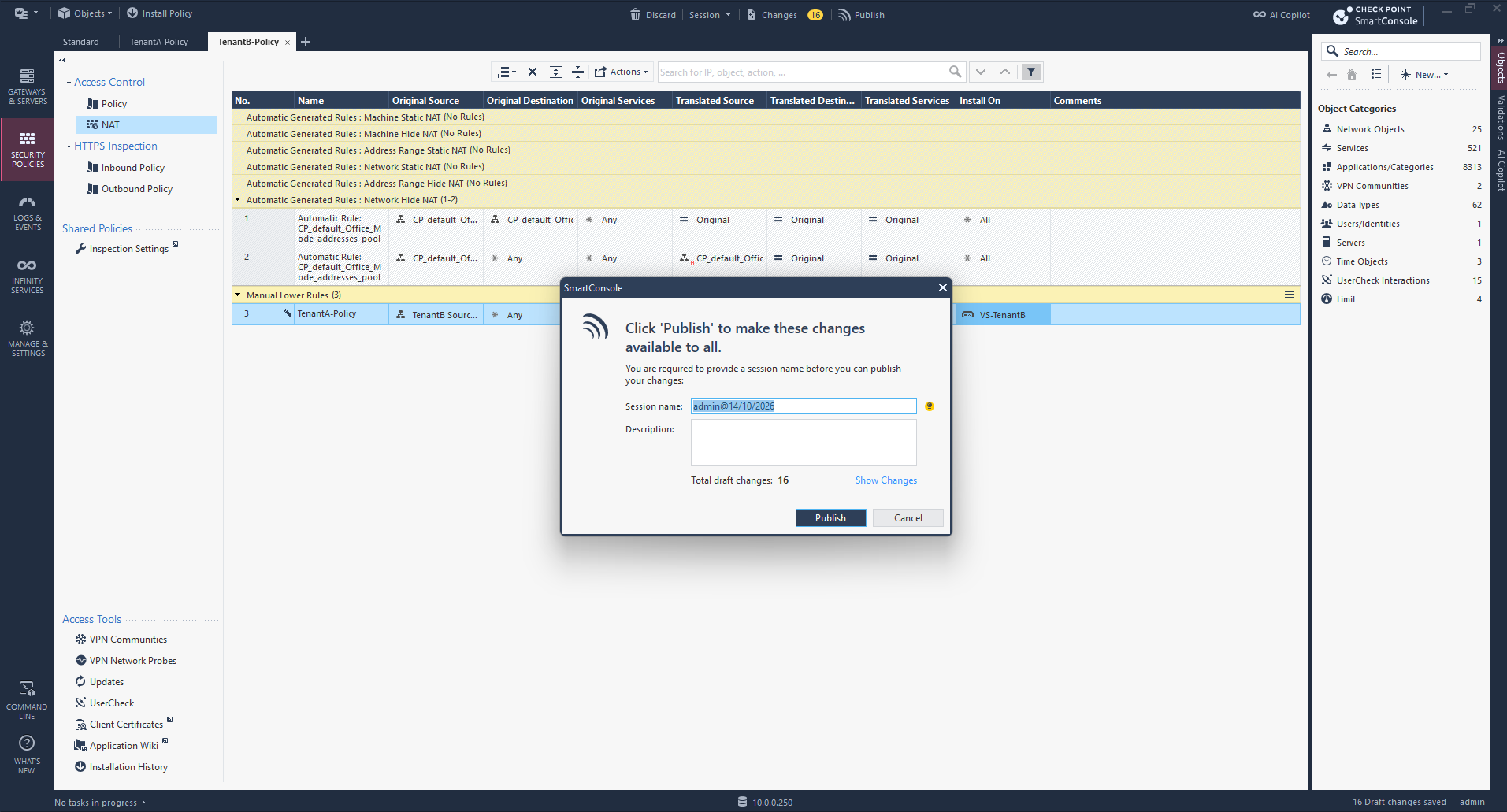
Finally, our manual NAT rule for TenantA is configured.
Traffic originating from 192.168.100.0/24 will be translated to 10.0.0.252 using Hide NAT, while the original destination and services remain unchanged.
The rule is installed exclusively on VS-TenantA.
Next, we repeat the same NAT configuration in TenantB-Policy, using 192.168.100.0/24 as the original source network but 10.0.0.253 as the Hide NAT address.
The rule is installed exclusively on VS-TenantB, keeping both tenants’ NAT configurations isolated despite their overlapping IP address ranges.
| Setting | Value |
|---|---|
| Original Source | 192.168.100.0/24 |
| Original Destination | Any |
| Original Services | Any |
| Translated Source | Hide behind 10.0.0.253 |
| Translated Destination | Original |
| Translated Services | Original |
| Install On | VS-TenantB |
For TenantB, we create the corresponding TenantB-NAT host object with IP address
10.0.0.253and assign it as the translated source in our manual NAT rule.The rule is applied exclusively to VS-TenantB, providing separate Hide NAT for both tenants despite their overlapping internal subnets.
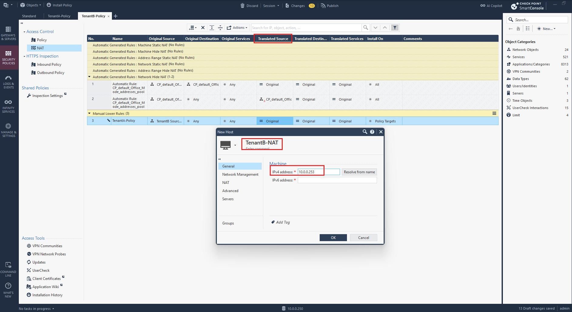
For TenantB-Policy, we configure the same Hide NAT method, translating the overlapping source network 192.168.100.0/24 to the dedicated IP address 10.0.0.253 using the TenantB-NAT object.
The NAT rule is installed exclusively on VS-TenantB.
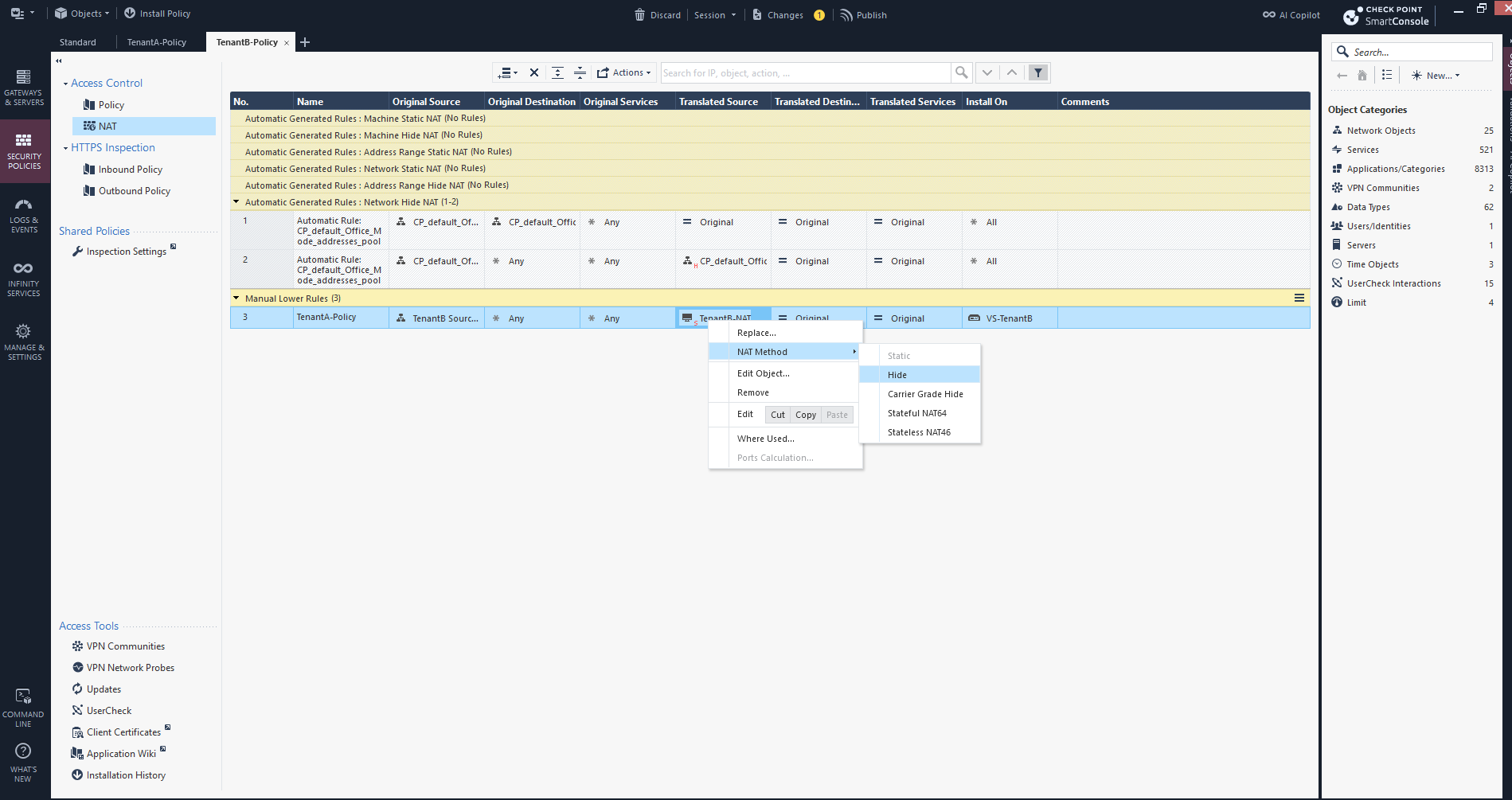
Finally, the manual NAT rule for TenantB is configured, translating its internal 192.168.100.0/24 subnet to 10.0.0.253 using Hide NAT.
With separate NAT rules assigned to VS-TenantA and VS-TenantB, both tenants can use identical internal IP addresses while maintaining independent NAT configurations.
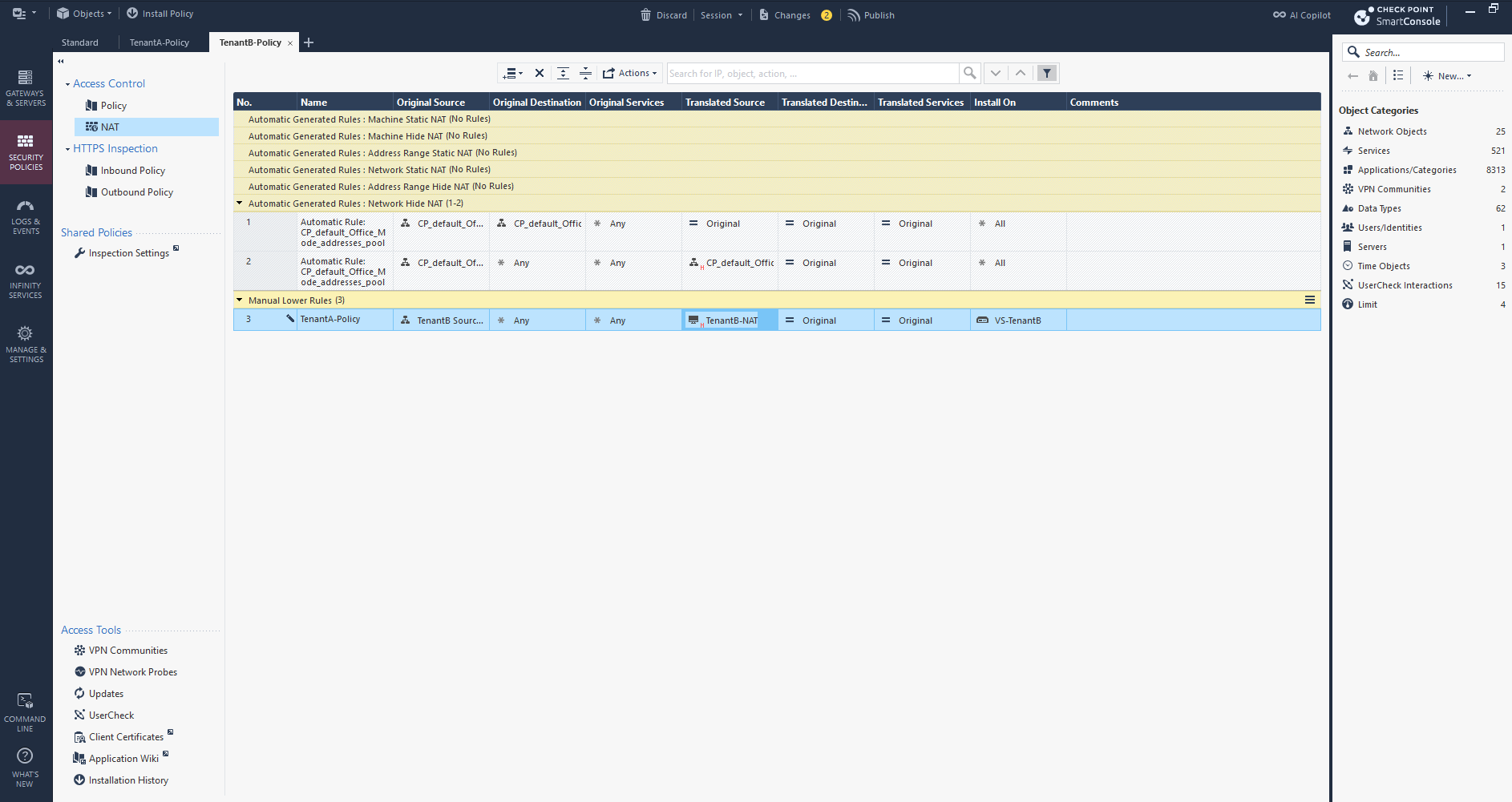
With the NAT rules configured for both Virtual Systems, we click Publish to save our changes to the Check Point Security Management database.
However, the new rules will only become active after we install the respective policy packages on VS-TenantA and VS-TenantB.
Configure Interface Topology and Static Return Routes for Both Virtual Systems (TenantA and TenantB)
Before installing the security policies, we need to configure the interface topology and static return routes for both Virtual Systems.
Since TenantA and TenantB use the same internal subnet 192.168.100.0/24, each Virtual System must recognize its respective tenant network and route return traffic through the corresponding NSX Tier-0 VRF interface (10.0.40.2 for TenantA and 10.0.41.2 for TenantB).
I will start with the TenantB Virtual System.
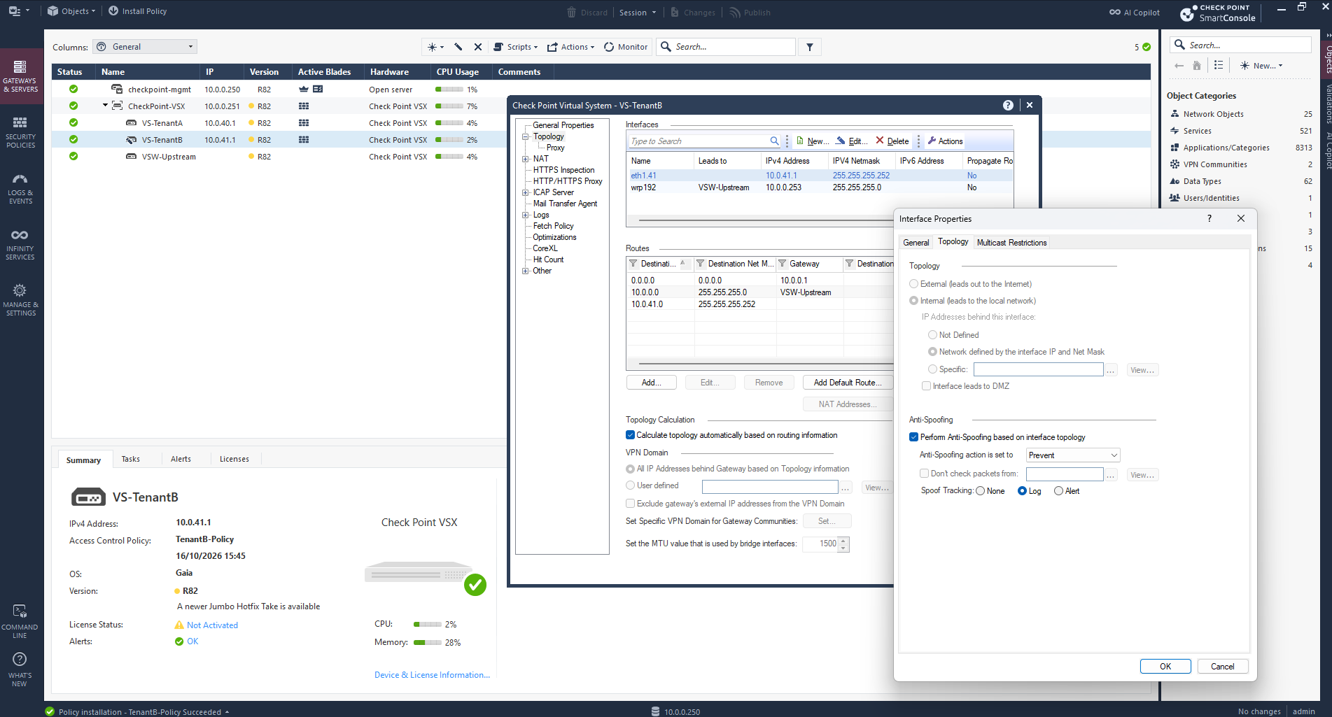
In SmartConsole, navigate to Gateways & Servers → VS-TenantB → Topology, select interface eth1.41, and click Edit → Topology.
Anti-Spoofing is enabled in Prevent mode, while the interface topology settings are greyed out because Calculate topology automatically based on routing information is enabled.
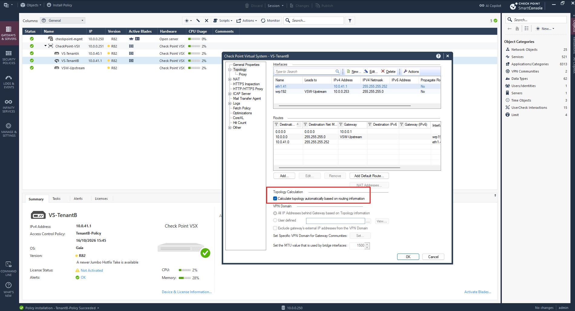
To configure the interface topology manually, we first uncheck Calculate topology automatically based on routing information under VS-TenantB → Topology.
This allows us to define the tenant network behind interface eth1.41 explicitly and adjust its Anti-Spoofing configuration.
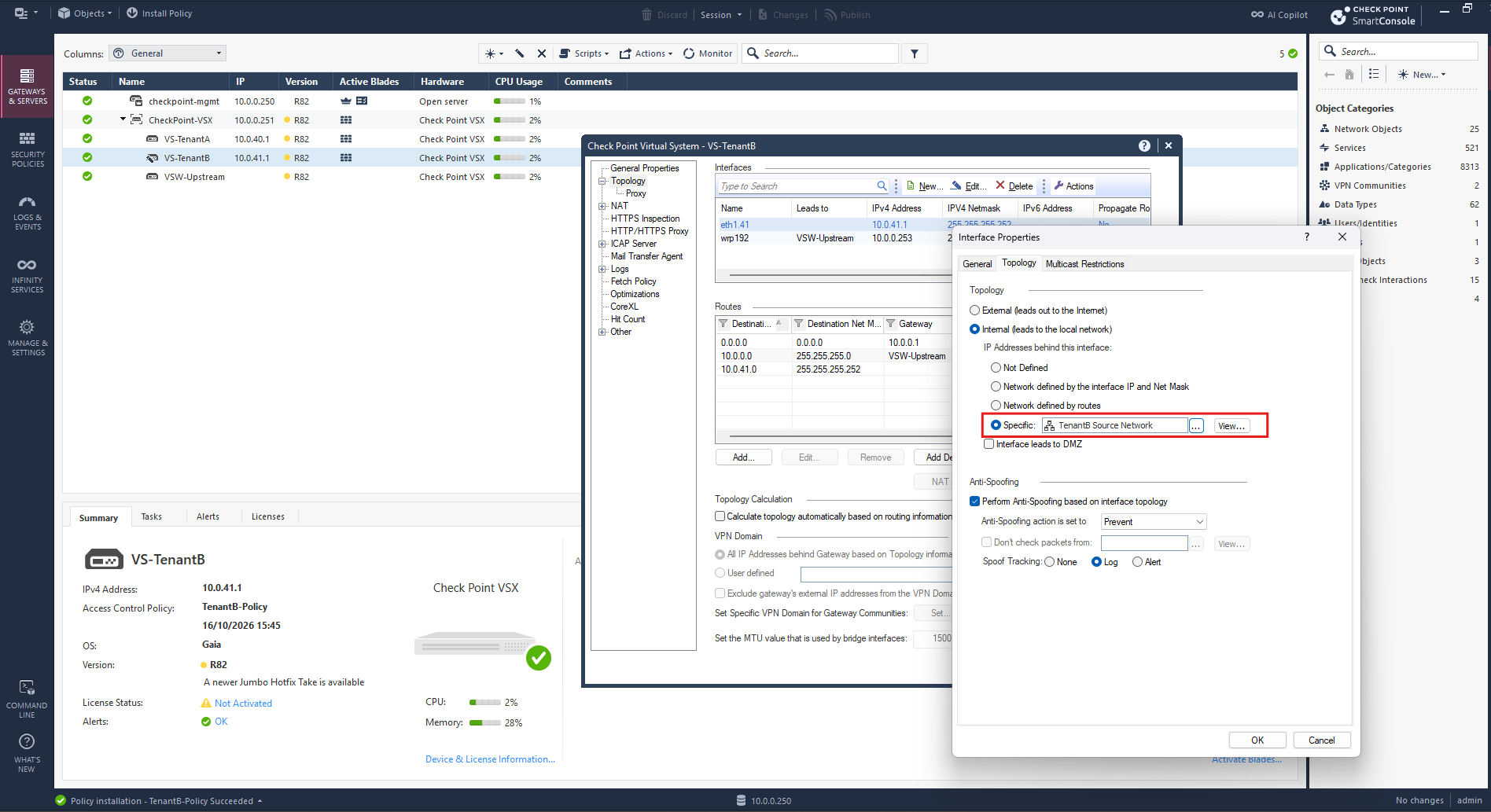
Under eth1.41 → Topology, we select Internal → Specific and assign the existing TenantB Source Network object (192.168.100.0/24). We keep Anti-Spoofing enabled in Prevent mode, allowing legitimate tenant traffic while continuing to block spoofed source addresses.
Without an explicit route to 192.168.100.0/24 via the NSX Tier-0 VRF, the replies would follow the default route back toward pfSense instead of reaching the tenant network.
We add a static route using the NSX Tier-0 VRF interface 10.0.41.2 as the next-hop gateway.
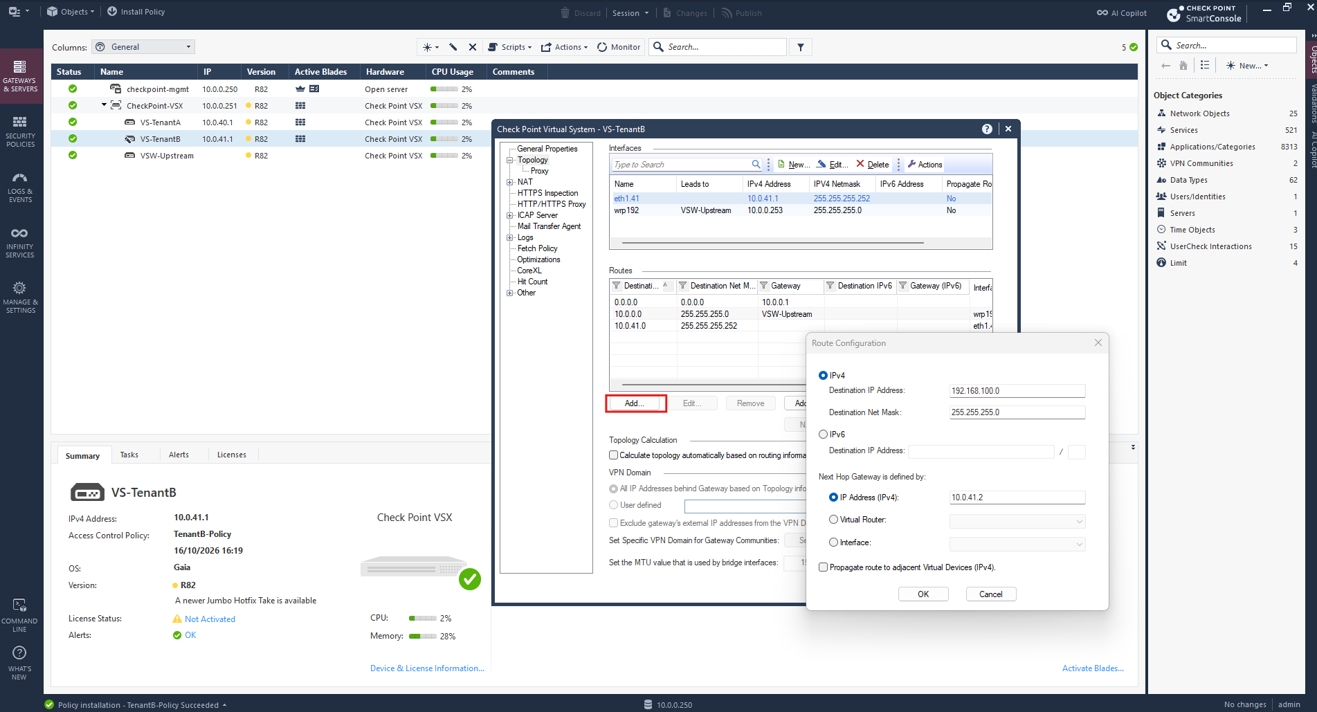
Click OK, then OK again in the Virtual System properties, Publish the changes, and reinstall TenantB-Policy.
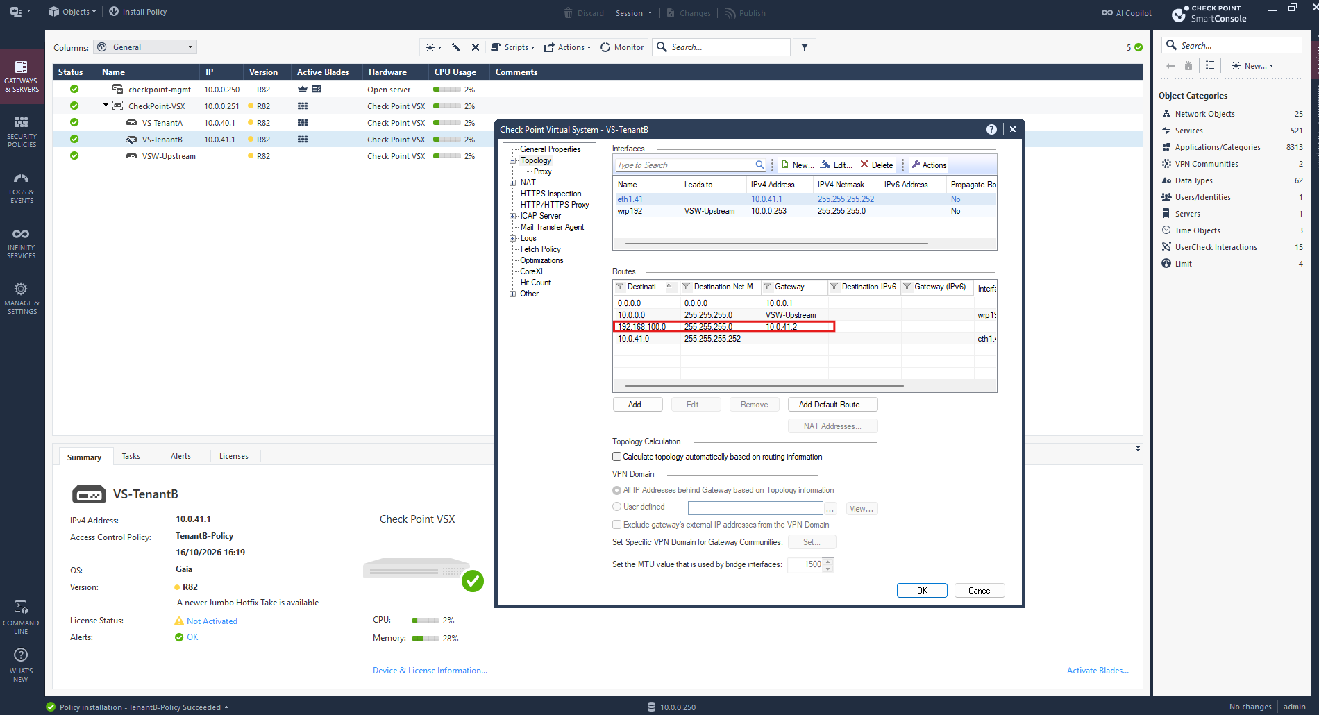
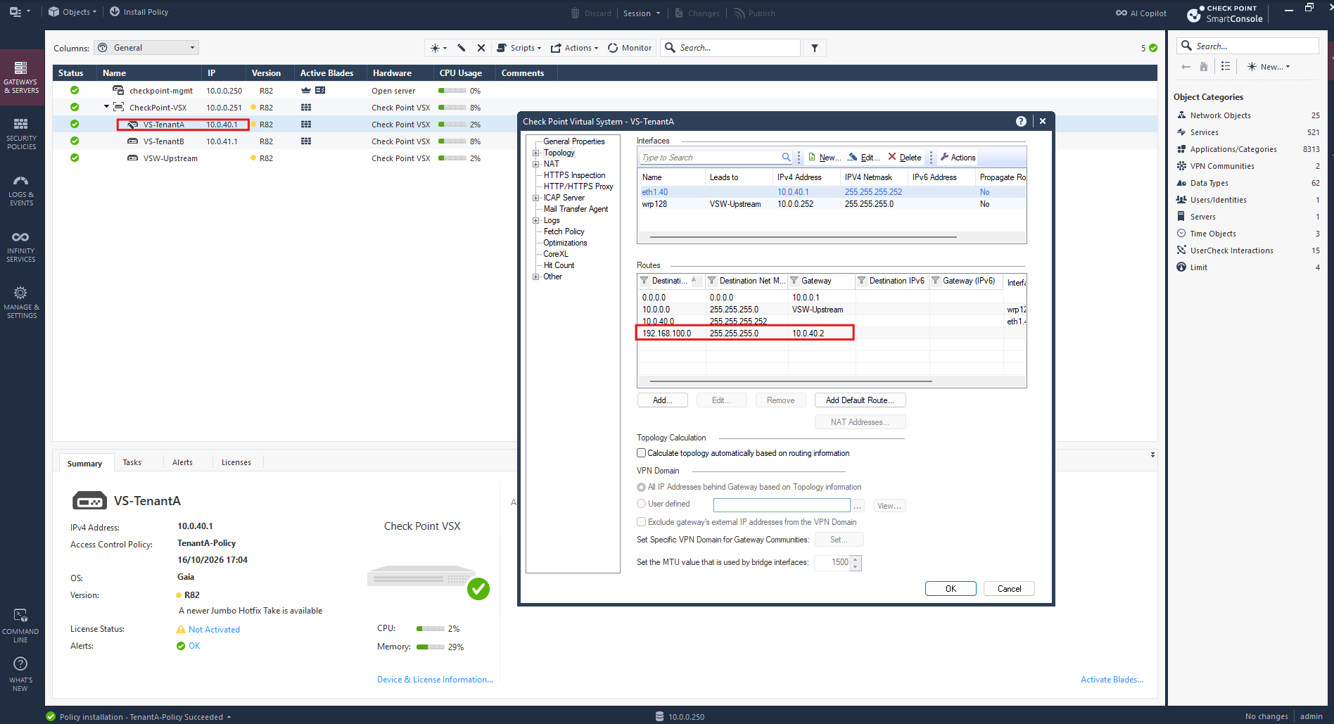
The same interface topology and static routing configuration must also be applied to VS-TenantA, using the identical destination network 192.168.100.0/24 but specifying 10.0.40.2 as the next-hop gateway instead of 10.0.41.2, which is used for TenantB.
Install the Security Policies on Both Virtual Systems
Next, we install our newly configured security policies on the corresponding Virtual Systems.
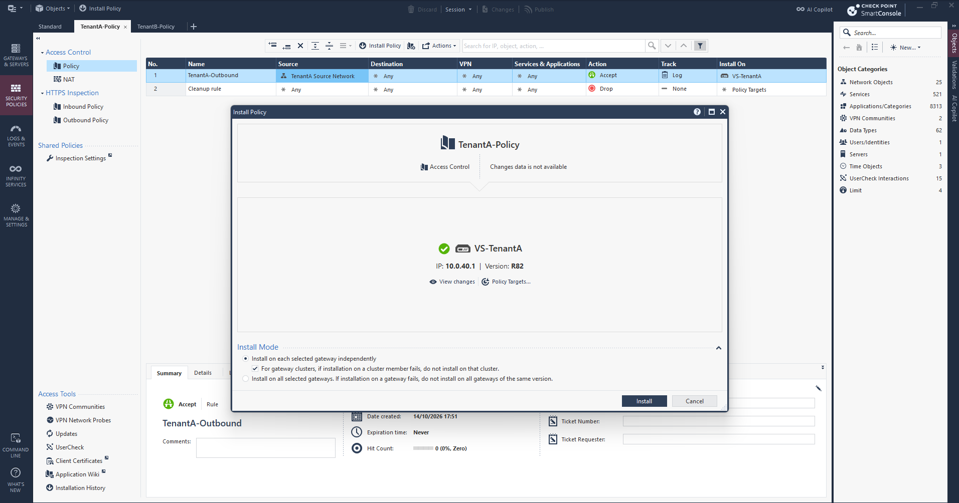
In SmartConsole, we click Install Policy, select TenantA-Policy with VS-TenantA as the installation target, and repeat the process for TenantB-Policy and VS-TenantB.
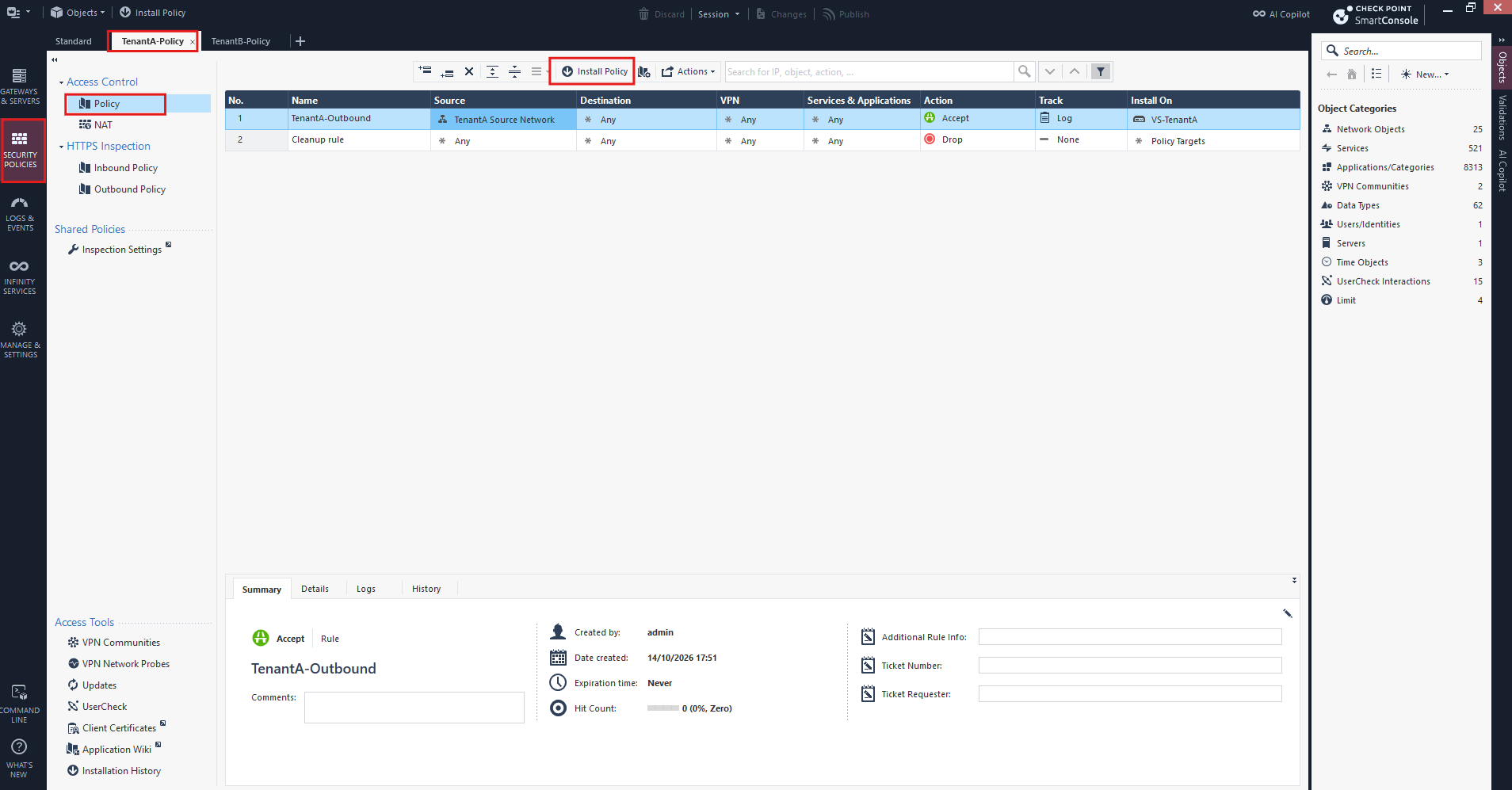
In the Install Policy dialog, we verify that TenantA-Policy is assigned to the correct Virtual System, VS-TenantA (10.0.40.1). We then click Install to deploy the Access Control and NAT policies.
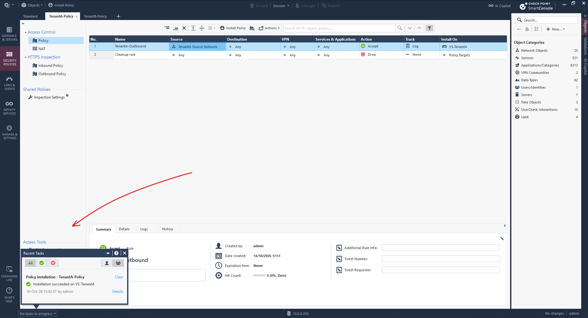
The TenantA-Policy installation completes successfully on VS-TenantA, as confirmed by the green status indicator in the Recent Tasks panel at the bottom-left of SmartConsole.
This confirms that the Access Control and NAT policy has been successfully deployed to the Virtual System.
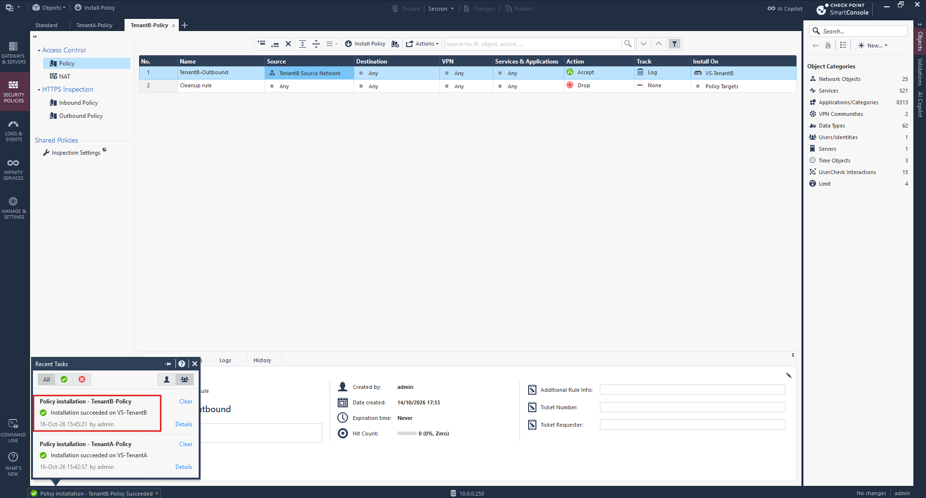
We repeat the same procedure for TenantB-Policy, selecting VS-TenantB (10.0.41.1) as the installation target.
Once the policy installation completes successfully, both Virtual Systems have their dedicated Access Control and NAT policies deployed.
Verify Simultaneous TCP Connections from Both Tenants to the Same Azure VM
To verify that both tenants can communicate simultaneously with the same external destination despite using identical internal IP addresses, I will establish separate RDP connections from TenantA and TenantB (both 192.168.100.10) to the same Windows VM hosted in Microsoft Azure.
Each Check Point Virtual System translates its tenant’s source address to a unique IP address (10.0.0.252 for TenantA and 10.0.0.253 for TenantB) before the traffic passes through pfSense and our FRITZ!Box. We then inspect the active TCP connections on the Azure VM to verify that both sessions can coexist without conflicts.
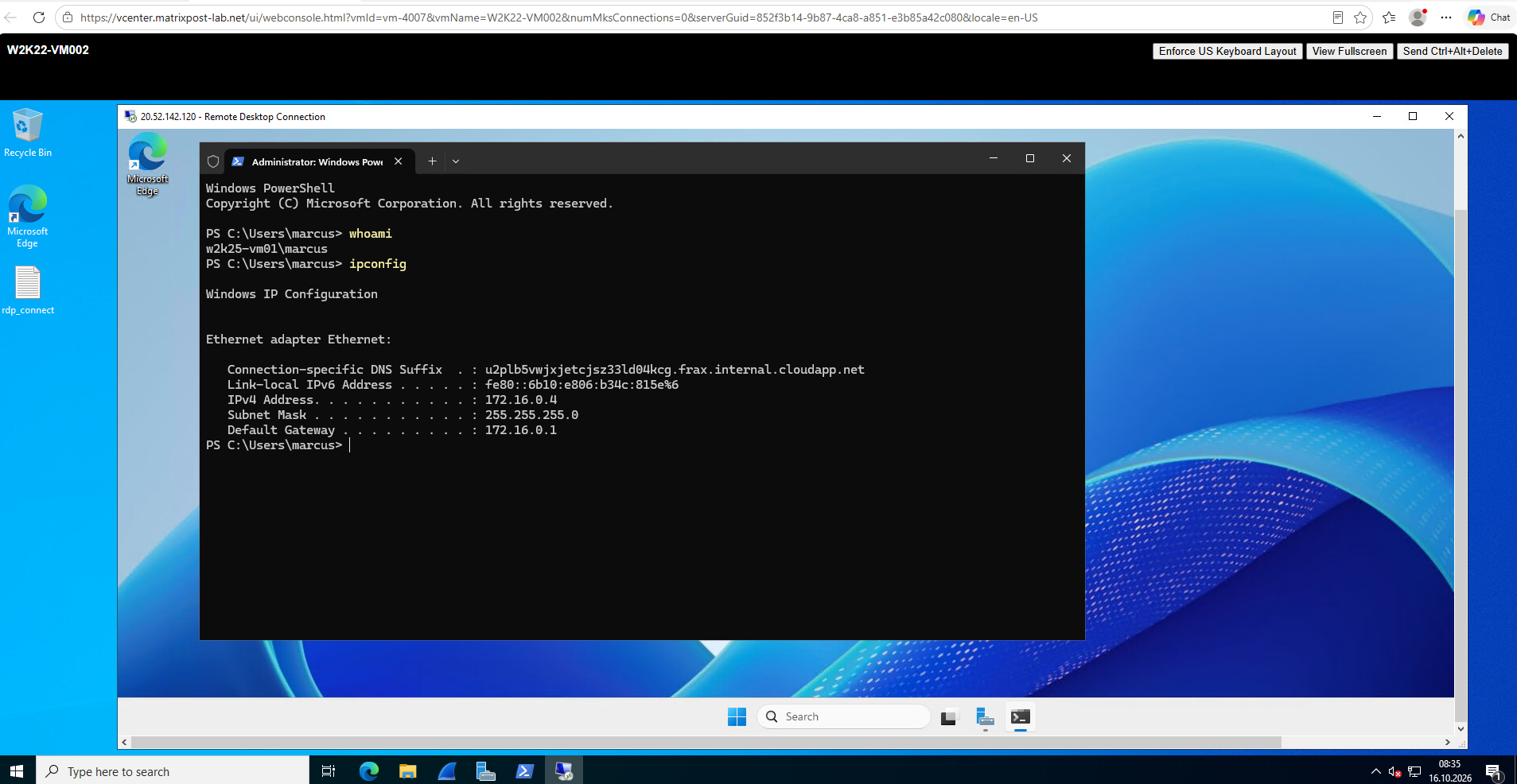
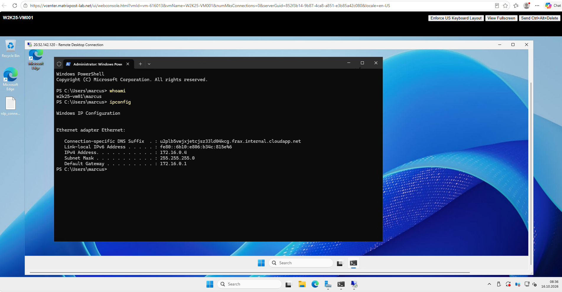
From my TenantA Windows Server 2022 VM, I successfully establish an RDP connection to the Azure VM using its public IP address 20.52.142.120.
The PowerShell output confirms that we are connected to the remote Azure VM with the private IP address 172.16.0.4.
Simultaneously, I establish a second RDP connection from my TenantB Windows Server 2025 VM to the same Azure VM at 20.52.142.120.
Both sessions remain active independently, demonstrating that the two tenants can access the same external destination despite using the identical internal source IP address
192.168.100.10.
pfSense – Verify simultaneous TCP sessions
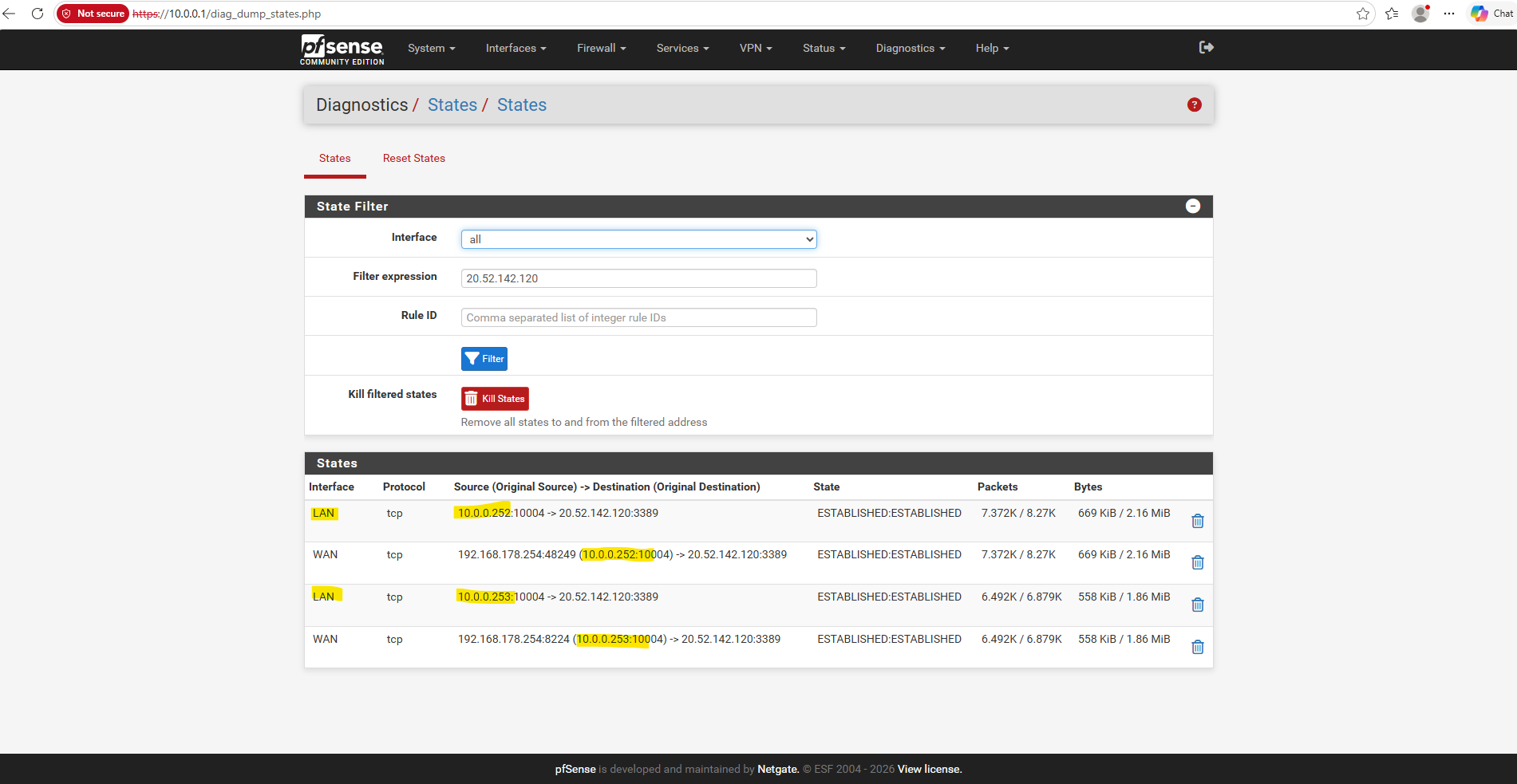
Navigate to Diagnostics → States in pfSense and filter for the Azure VM’s public IP address 20.52.142.120.
The state table confirms two simultaneous, established RDP connections on TCP port 3389, originating from 10.0.0.252 (
TenantA) and 10.0.0.253 (TenantB), which pfSense subsequently translates to its WAN address192.168.178.254using separate source ports.Notice: the particularly nice detail, both tenants use source port 10004, yet the connections remain independent because Check Point translates them to different source IP addresses before they reach pfSense.
Check Point – Verify simultaneous TCP sessions using Logs & Events
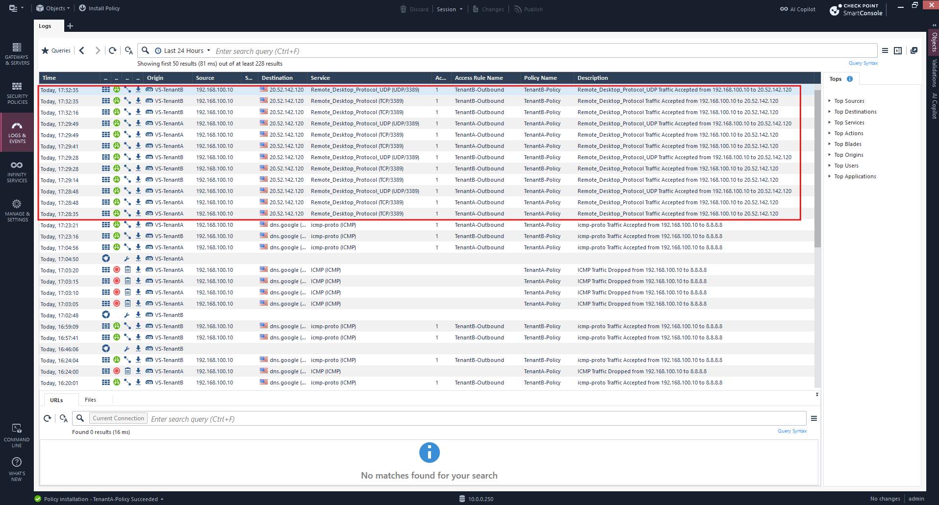
In Check Point SmartConsole → Logs & Events, we can also monitor the simultaneous RDP connections from both virtual systems.
Although TenantA and TenantB use the identical internal source IP address 192.168.100.10, their traffic is processed independently by the respective security policies and translated to 10.0.0.252 and 10.0.0.253 before being forwarded upstream.
In the logs we can see both virtual systems simultaneously accepting RDP traffic from the identical source IP address
192.168.100.10to our Azure VM20.52.142.120on TCP port 3389.The logs clearly distinguish VS-TenantA and VS-TenantB, with each connection matching its respective TenantA-Outbound or TenantB-Outbound firewall rule and security policy.
Check Point – Verify Simultaneous TCP Sessions Using tcpdump in Expert Mode
In addition to verifying TCP sessions through the Check Point Logs & Events interface, we can use the Command Line Interface (CLI) in Expert Mode to capture and inspect live network traffic directly on the VSX Gateway.
By switching between the individual Virtual Systems using vsenv and capturing packets with tcpdump, we can verify how traffic flows through each tenant environment, inspect the original source and destination IP addresses, and troubleshoot connectivity or NAT-related issues.
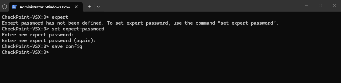
Before entering Expert mode for the first time, we need to configure an Expert password using set expert-password in Gaia Clish and save the configuration with save config. Afterward, we can enter Expert mode by executing expert and providing the configured password.
set expert-password
save config
After connecting to the Check Point VSX Gateway via SSH and entering Expert mode, we execute vsx stat -v to display the status of all Virtual Devices.
The output confirms that VS-TenantA (VSID 2) and VS-TenantB (VSID 3) are active, their respective security policies are installed, and SIC trust is established.
SIC (Secure Internal Communication) is Check Point’s mechanism for establishing authenticated and encrypted communication between the Security Management Server and managed gateways or Virtual Systems.
expert
vsx stat -v
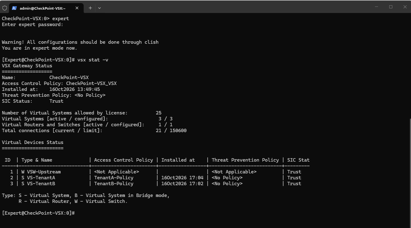
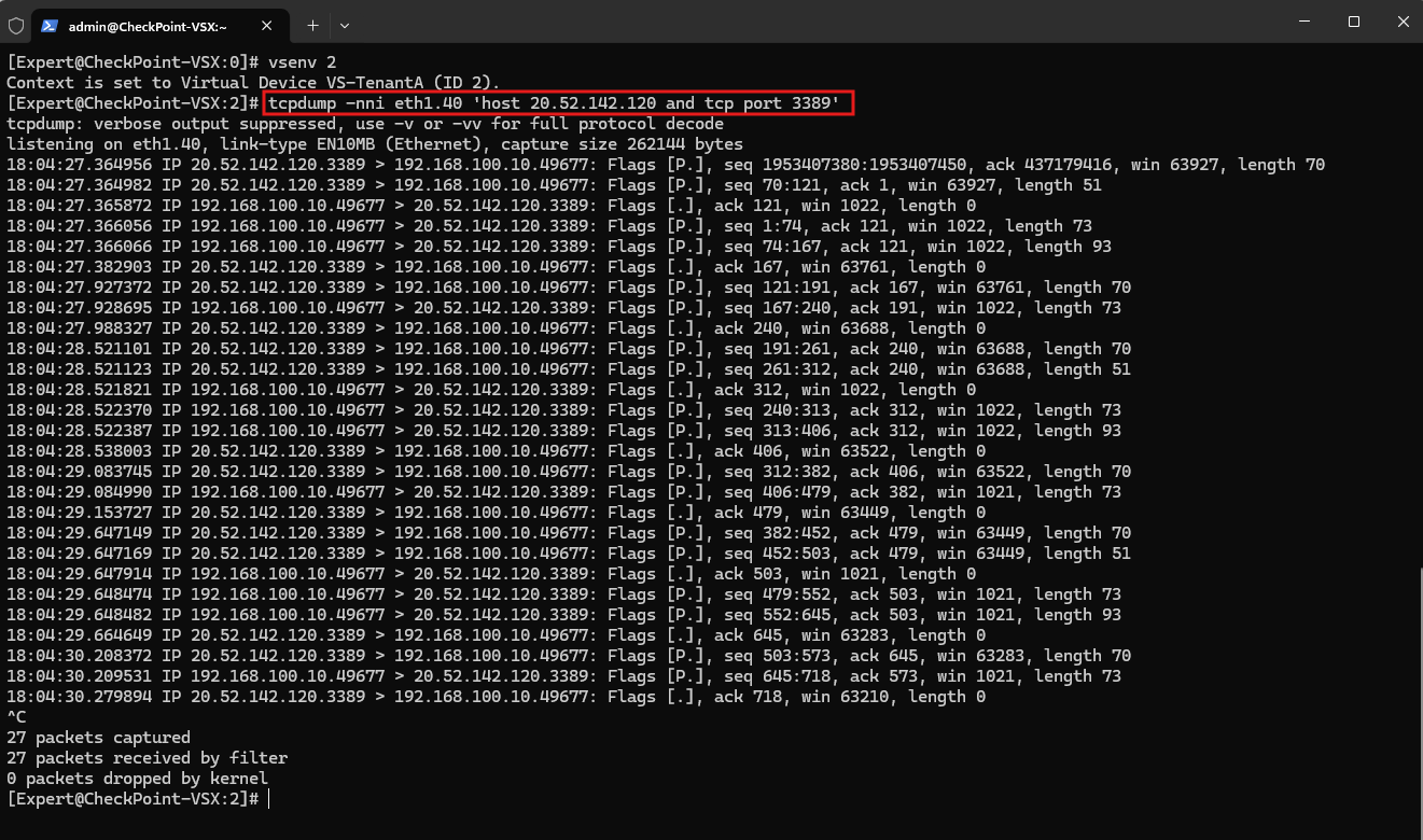
Next, we use vsenv 2 to switch to VS-TenantA (VSID 2) and capture live RDP traffic on interface eth1.40 using tcpdump.
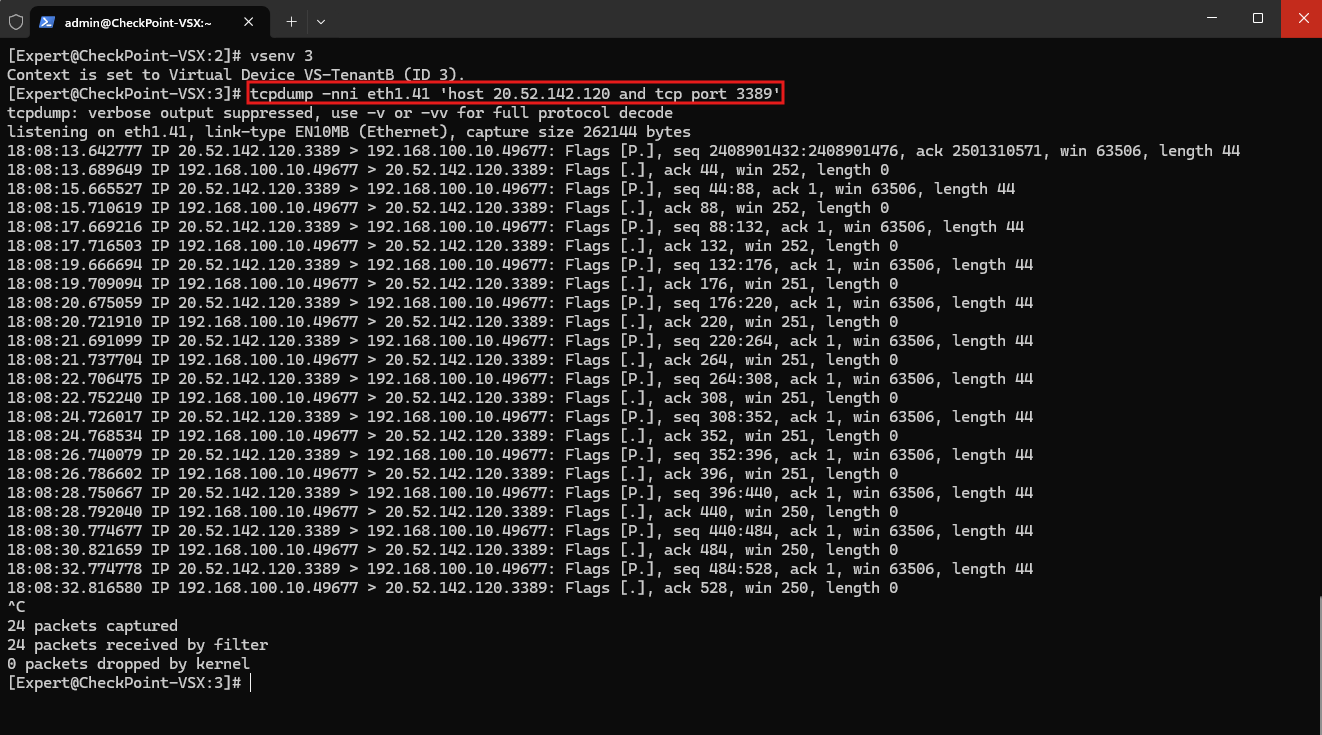
We then repeat the procedure with vsenv 3 for VS-TenantB (VSID 3) on interface eth1.41, allowing us to observe how both Virtual Systems independently handle traffic from the identical source IP address 192.168.100.10.
First, we switch to VS-TenantA (VSID 2):
vsenv 2
Then capture traffic on the tenant-facing interface eth1.40:
The output shows TCP packets flowing in both directions between the original tenant IP address
192.168.100.10and our Azure VM20.52.142.120on port 3389, confirming successful communication before source NAT is applied.
tcpdump -nni eth1.40 'host 20.52.142.120 and tcp port 3389'
Next, we switch to VS-TenantB (VSID 3) using vsenv 3 and capture the same RDP traffic on its tenant-facing interface eth1.41.
The output again shows bidirectional TCP communication between
192.168.100.10and 20.52.142.120 on port 3389, confirming that the traffic reachesVS-TenantBwhile still retaining its original source IP address.
vsenv 3
tcpdump -nni eth1.41 'host 20.52.142.120 and tcp port 3389'
Final Thoughts – Elegant Handling of Overlapping Tenant Networks with Check Point VSX
One of the most elegant aspects of Check Point VSX is how seamlessly it handles overlapping tenant address spaces, even when different tenants use identical host IP addresses.
Each Virtual System operates within its own isolated routing and firewall context, allowing the same IP addresses and subnets to coexist without conflicts.
Compared to our previous Ubuntu-based solution, where we had to manually configure network namespaces, routing, firewall rules, and NAT to achieve the same isolation, Check Point VSX provides a much more integrated and manageable approach.
This demonstrates the advantage of a purpose-built multi-tenant firewall platform, especially as the number of tenants and overlapping networks increases.
Interestingly, Check Point Gaia is itself a Linux-based operating system, historically derived from Red Hat Enterprise Linux (RHEL). Under the hood, Check Point VSX follows many of the same fundamental networking principles we previously implemented manually on Ubuntu, including isolated routing contexts, firewall policies, VLAN interfaces, and Network Address Translation (NAT).
However, while our Ubuntu solution relied on standard Linux network namespaces, routing tables, and iptables/nftables rules, Check Point VSX uses its own virtualization architecture and proprietary firewall components to provide isolated Virtual Systems.
In other words, the networking concepts are essentially the same, but the underlying implementation is different. What required considerable manual configuration on Ubuntu is integrated into a centrally managed, purpose-built multi-tenant firewall platform with Check Point VSX.
Troubleshooting
During our initial connectivity tests, both TenantA and TenantB failed to reach 8.8.8.8.
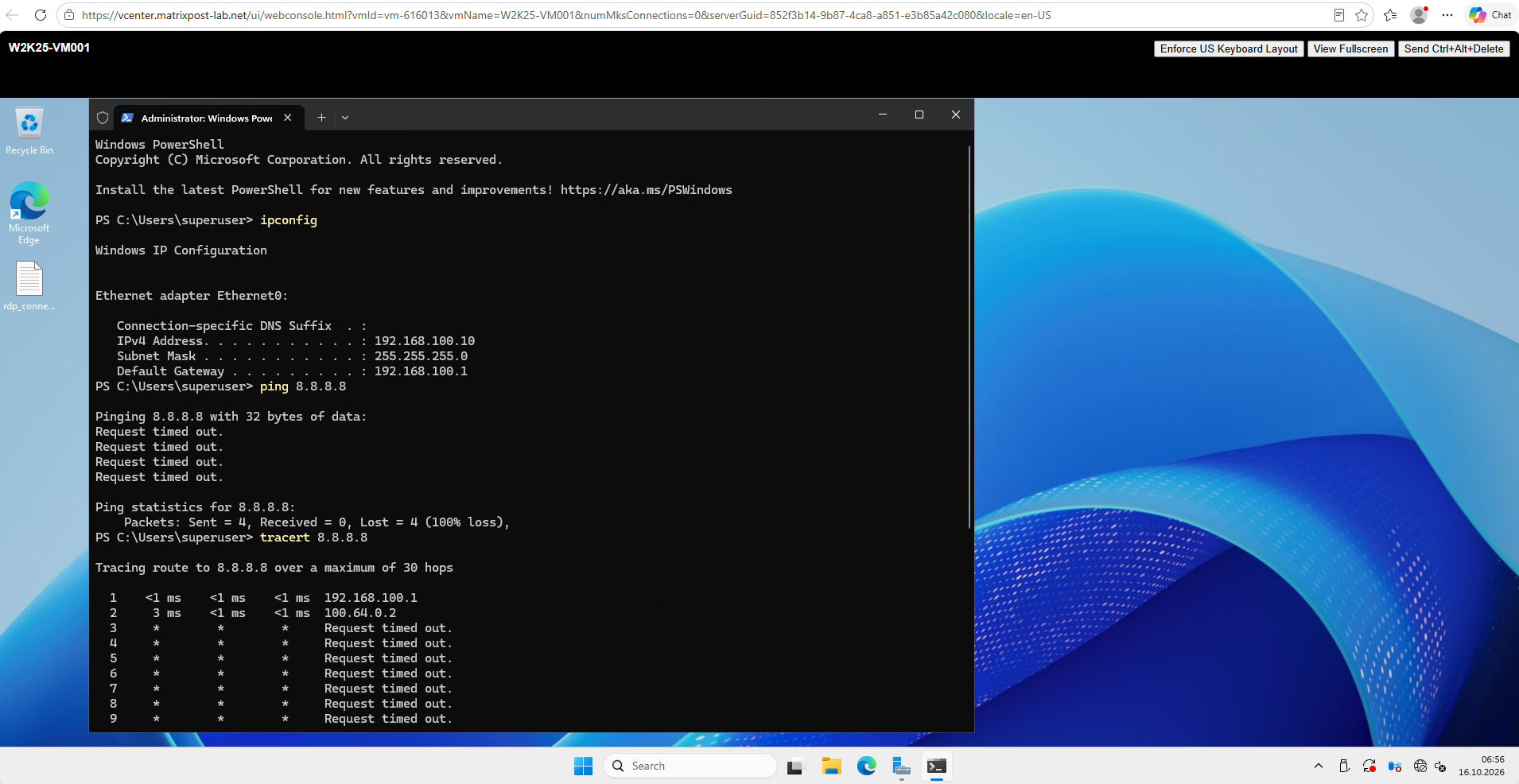
Checking Logs & Events in SmartConsole.
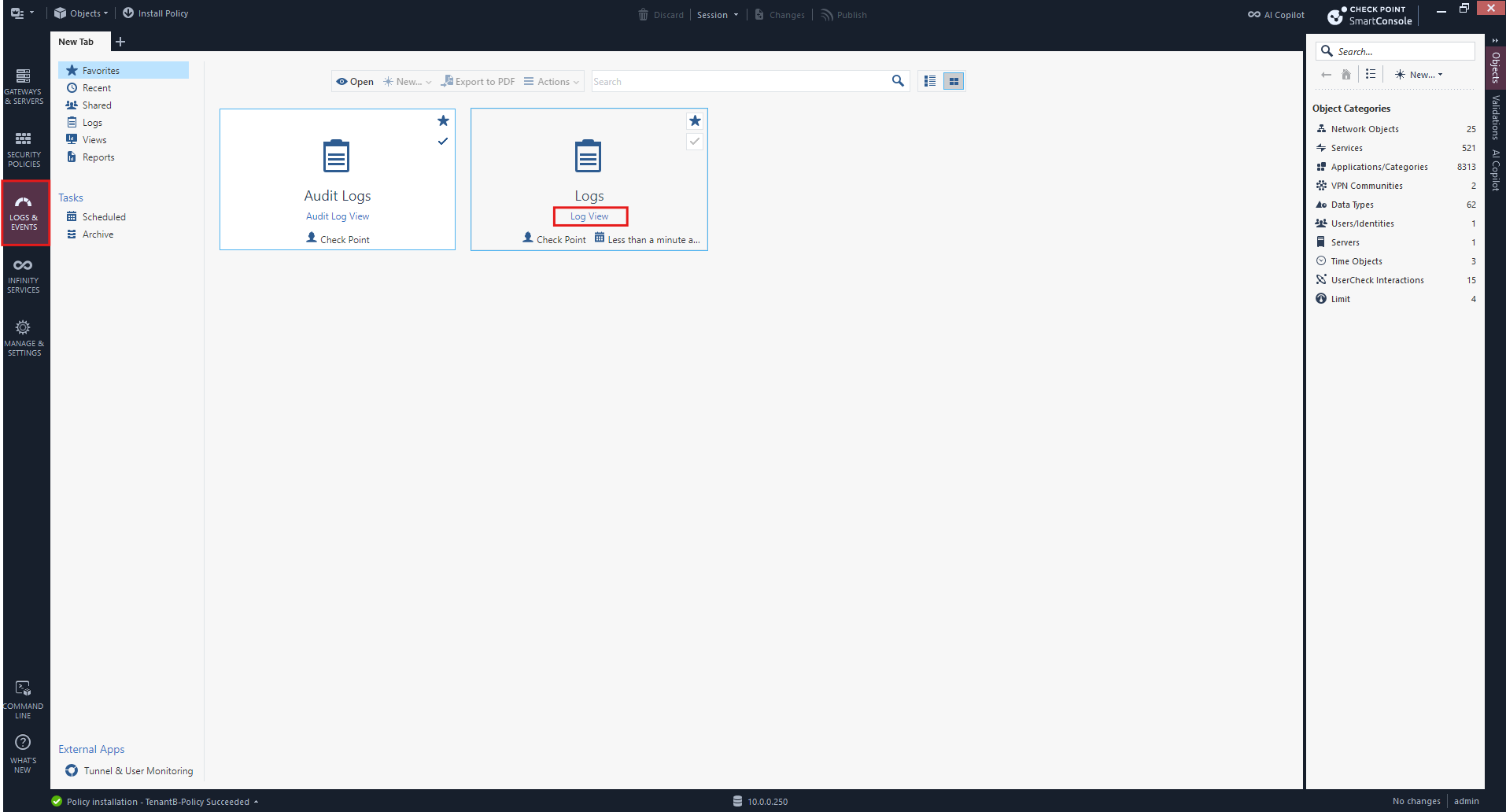
Enter the following in the search bar:
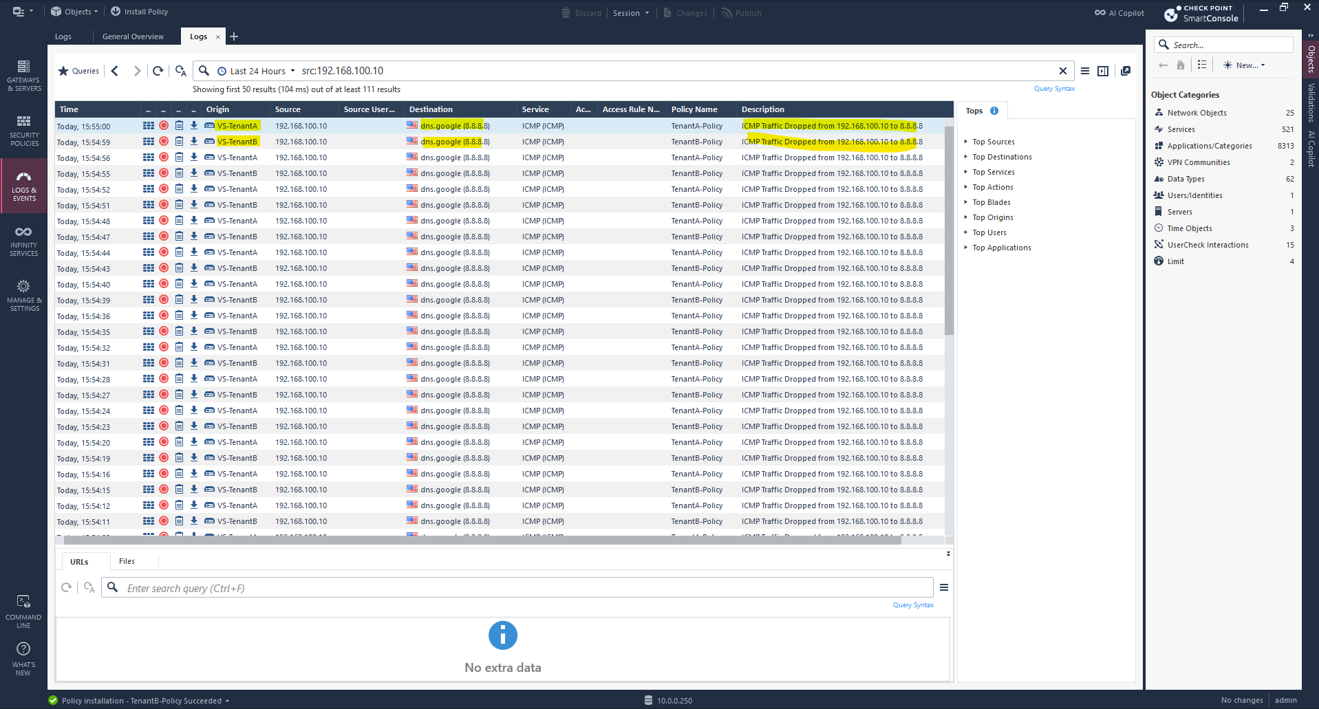
src:192.168.100.10
However, checking Logs & Events in SmartConsole confirms that traffic from both overlapping 192.168.100.0/24 networks successfully reaches their respective Virtual Systems, VS-TenantA and VS-TenantB, but is dropped by Check Point.
This confirms that routing to the Virtual Systems is working and narrows our troubleshooting to the firewall configuration.
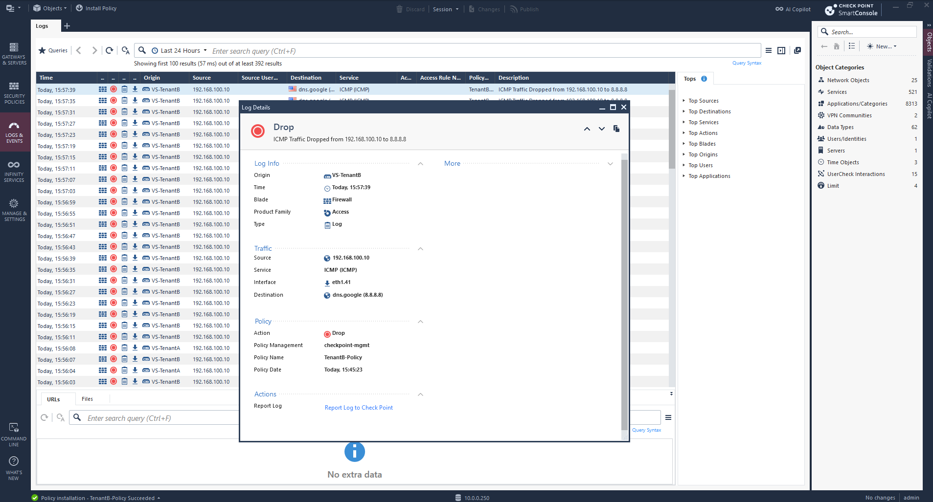
Inspecting the dropped traffic in Log Details confirms that VS-TenantB receives ICMP packets from 192.168.100.10 on interface eth1.41, but the Firewall blade drops them despite the installed outbound Accept rule.
Since no matching Access Control rule is identified in the log, we will investigate the interface topology and Anti-Spoofing configuration as a possible cause.
In SmartConsole, navigate to Gateways & Servers → VS-TenantB → Topology, select interface eth1.41, and click Edit → Topology.
Anti-Spoofing is enabled in Prevent mode, while the interface topology settings are greyed out because Calculate topology automatically based on routing information is enabled.
This is presumably causing our connectivity issue, as the actual tenant network
192.168.100.0/24might not be recognized as a valid source network behind this interface.
To configure the interface topology manually, we first uncheck Calculate topology automatically based on routing information under VS-TenantB → Topology.
This allows us to define the tenant network behind interface eth1.41 explicitly and adjust its Anti-Spoofing configuration.
Under eth1.41 → Topology, we select Internal → Specific and assign the existing TenantB Source Network object (192.168.100.0/24). We keep Anti-Spoofing enabled in Prevent mode, allowing legitimate tenant traffic while continuing to block spoofed source addresses.
Next, click OK, save the Virtual System configuration, Publish, and reinstall TenantB-Policy.
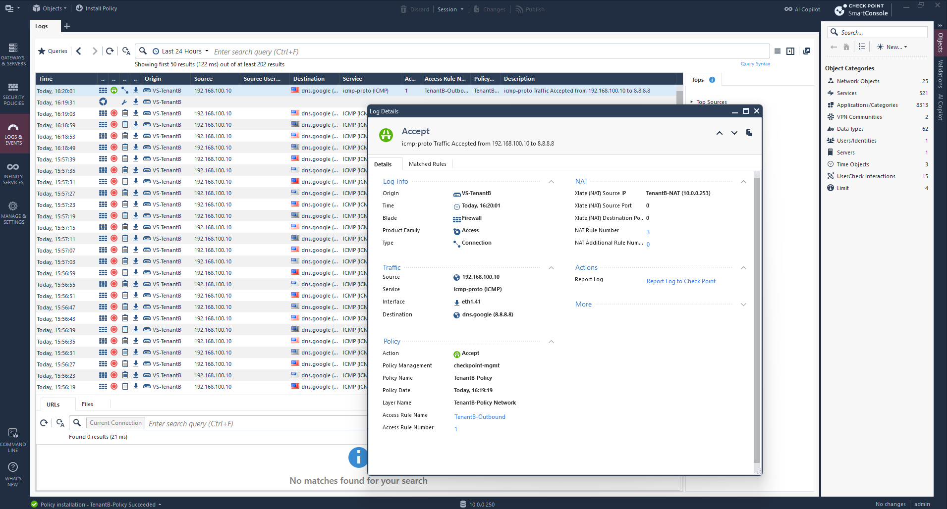
After correcting the interface topology and reinstalling TenantB-Policy, the firewall logs now show that ICMP traffic from 192.168.100.10 is accepted by the TenantB-Outbound rule.
The logs also confirm that Hide NAT translates the source address to
10.0.0.253, although the client still receives no ping replies, so we will investigate the upstream connectivity next.
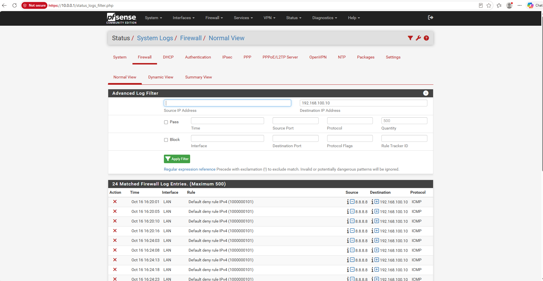
Checking pfSense → Status → System Logs → Firewall reveals that ICMP packets from 8.8.8.8 to 192.168.100.10 are blocked by the Default deny rule IPv4 on the LAN interface.
However, since Check Point should translate the tenant source address to
10.0.0.253, the unexpected destination address suggests that we need to investigate whether Hide NAT is actually being applied to the forwarded traffic.
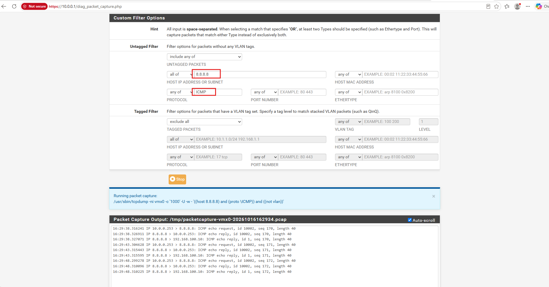
Using pfSense → Diagnostics → Packet Capture on the LAN interface confirms that Check Point successfully translates TenantB’s source address to 10.0.0.253 and that ICMP replies return from 8.8.8.8.
However, the capture also shows replies addressed to the original tenant IP
192.168.100.10, indicating an unexpected additional translation that we need to investigate in pfSense.
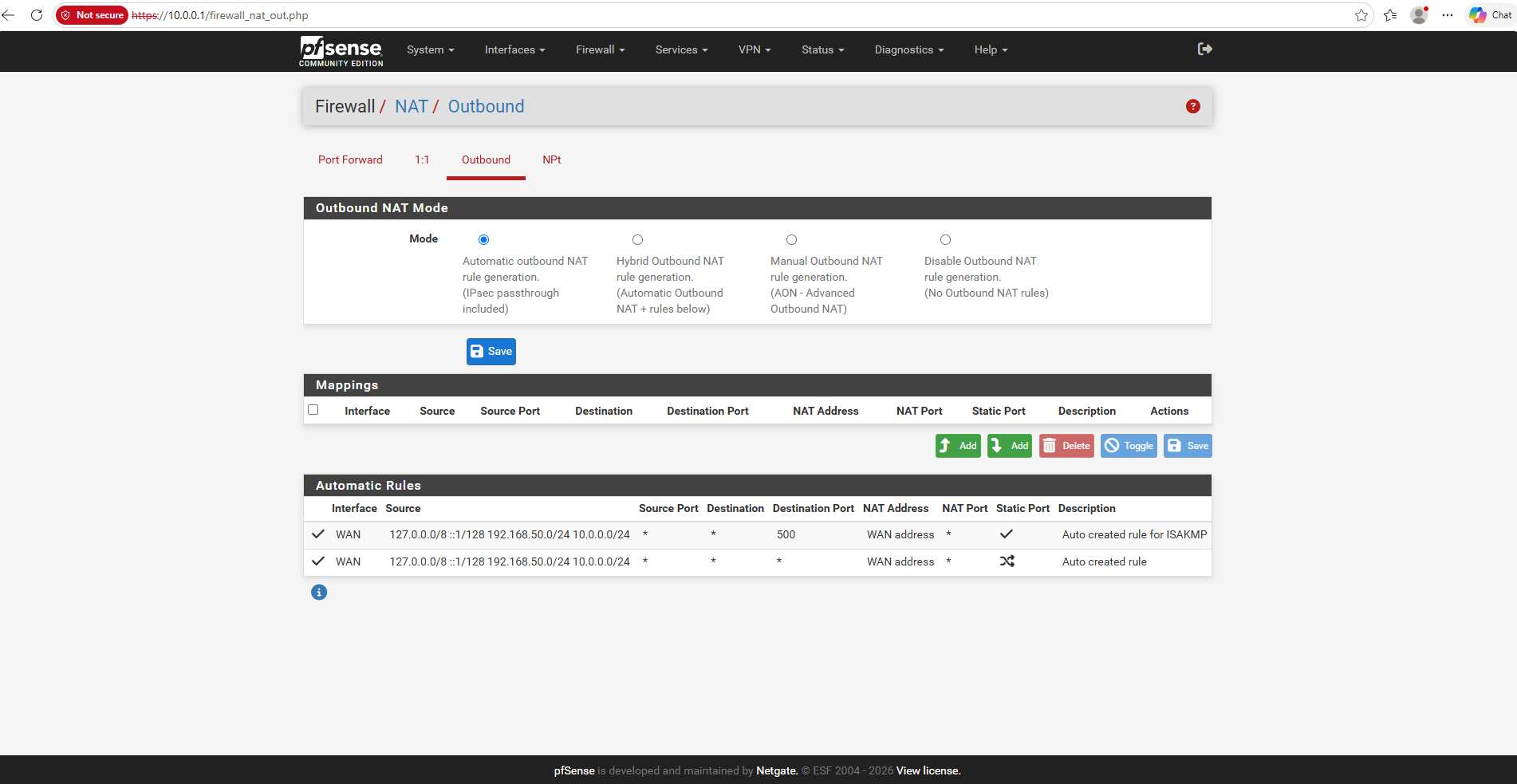
On pfSense, we navigate to Firewall → NAT → Outbound, where Automatic Outbound NAT is currently enabled.
The automatically generated rules do not explicitly include our Check Point NAT addresses 10.0.0.252 and 10.0.0.253, but the packet captures and firewall states confirm that pfSense successfully translates the outgoing traffic to its WAN address.
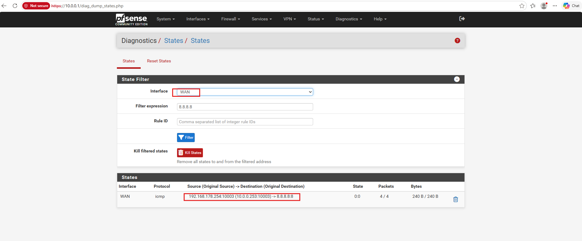
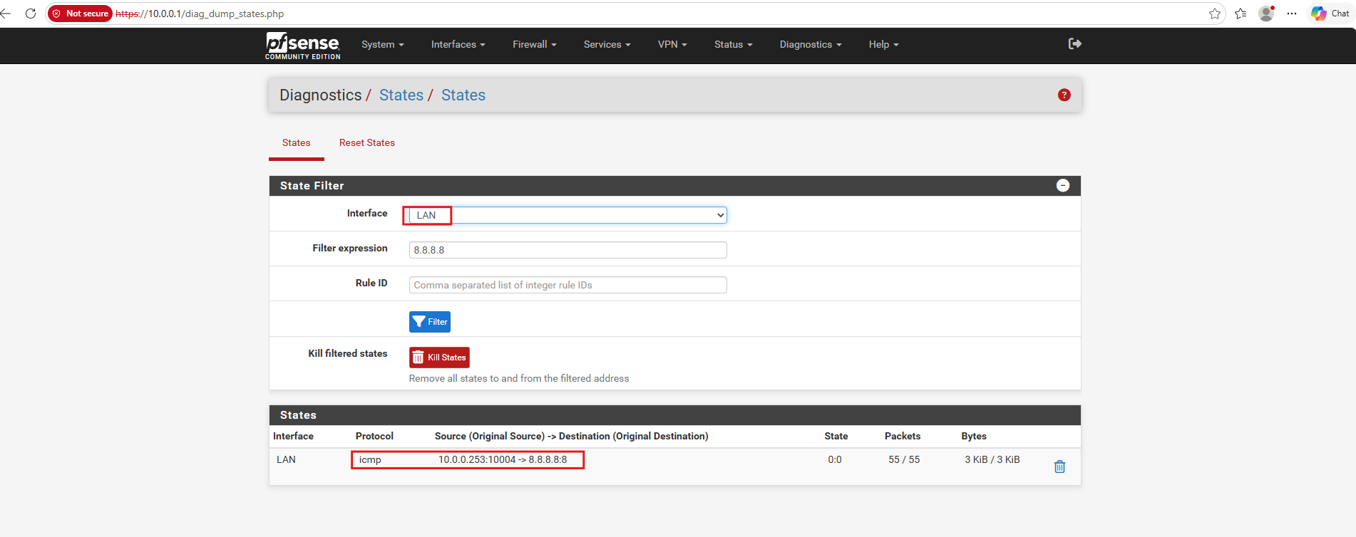
Since the Check Point logs now confirm that outbound traffic is accepted and correctly translated using Hide NAT, but the ICMP replies still do not reach the client, we suspect a missing return route on the Virtual System.
Without an explicit route to 192.168.100.0/24 via the NSX Tier-0 VRF, the replies would follow the default route back toward pfSense instead of reaching the tenant network.
As suspected, the routing table of VS-TenantB does not contain a return route to the tenant network 192.168.100.0/24, so we add a static route using the NSX Tier-0 VRF interface 10.0.41.2 as the next-hop gateway.
Click OK, then OK again in the Virtual System properties, Publish the changes, and reinstall TenantB-Policy.
After adding the missing return route, TenantB can successfully reach the Internet, as confirmed by a ping to 8.8.8.8 with 0% packet loss.
The traceroute confirms that traffic passes through the NSX Tier-0 VRF, Check Point VS-TenantB (10.0.41.1), pfSense (10.0.0.1), and my FRITZ!Box (192.168.178.1) before reaching the Internet.
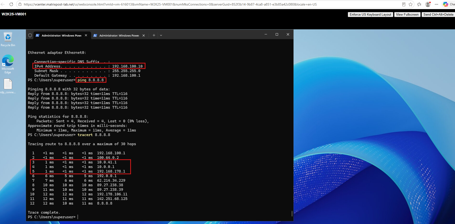
To enable Internet connectivity for TenantA as well, we need to repeat the same configuration changes on VS-TenantA: adjust the interface topology by setting Leads to to the appropriate internal network and add a static return route for 192.168.100.0/24 via the TenantA Tier-0 VRF interface 10.0.40.2.
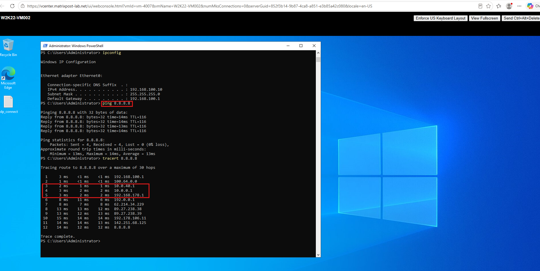
After applying the same topology and routing changes to VS-TenantA, Internet connectivity is now working for TenantA as well, with 0% packet loss when pinging 8.8.8.8.
The traceroute confirms that traffic passes through the dedicated Check Point Virtual System (
10.0.40.1), pfSense (10.0.0.1), and my FRITZ!Box (192.168.178.1), successfully demonstrating Internet access for both tenants despite their overlapping IP networks.
Links
Check Point R82 Gaia Clean Install – ISO
https://support.checkpoint.com/results/download/135012