Step-by-Step Guide: Setting up Classic VPN with Static Routes between Google Cloud and On-Prem by using Juniper vSRX3
In this post, we will see step by step how to configure a Classic VPN with static routes between Google Cloud Platform (GCP) and an on-premises Juniper vSRX3 firewall.
While GCP’s HA VPN relies on dynamic routing with BGP and shown in last post, Classic VPN with static routes offers a simpler approach for environments that don’t require or can’t support BGP.
GCP Cloud VPN offers two types of Cloud VPN gateways, HA VPN and Classic VPN.
Classic VPN was in 2022 already partial deprecated and therefore I was using HA VPN.
Meanwhile as of August 1, 2025, so just a few days ago of writing this post, the creation of Classic VPN tunnels using dynamic routing (BGP) is no longer supported, regardless of the gateway the tunnel connects to. This includes connections to VPN gateway software running inside a Compute Engine virtual machine (VM) instance or connections outside of Google Cloud.
!! Note !!
Classic VPN tunnels using static routing from Classic VPN gateways to on-premises VPN gateways and from on-premises VPN gateways to Classic VPN gateways are still supported and shown in this post.Nevertheless, Google recommends that you only retain Classic VPN if your on-premises VPN devices don’t support BGP, and therefore HA VPN cannot be used.
Cloud VPN Limitations
Cloud VPN does not support routing public internet traffic through on-premises like in Azure.
If you need centralized inspection in GCP, you’d typically deploy firewall/inspection appliances inside a hub VPC, not route traffic out through Cloud VPN.
Understanding Route-Based IPsec VPNs
With route-based VPNs, you can configure dozens of security policies to regulate traffic flowing through a single VPN tunnel between two sites, and there is just one set of IKE and IPsec SAs at work.
Unlike policy-based VPNs, for route-based VPNs, a policy refers to a destination address, not a VPN tunnel.
When Junos OS looks up a route to find the interface to use to send traffic to the packet’s destination address, it finds a route through a secure tunnel interface (st0.x).
The tunnel interface is bound to a specific VPN tunnel, and the traffic is routed to the tunnel if the policy action is permit.
Set up the Tunnel in GCP
To set up the VPN tunnel in GCP we first need to create a Classic VPN gateway.
Google Cloud Classic VPN was the original VPN service in GCP that supported both:
- Policy-based VPNs (matching traffic selectors / proxy IDs)
- Route-based VPNs as of August 1, 2025 just static routing, the dynamic (BGP) routing is not supported anymore and you have to use here HA VPN as shown in my last post.
Think of the Classic VPN gateway as the GCP-side VPN appliance you connect your on-prem firewall/router. It uses a single gateway per tunnel (no built-in redundancy), so if the gateway fails, the tunnel drops.
Google replaced it with HA VPN, which provides two redundant gateways in different zones for higher availability and now is the recommended option.
Classic VPN is being phased out for certain configurations (especially like mentioned BGP).
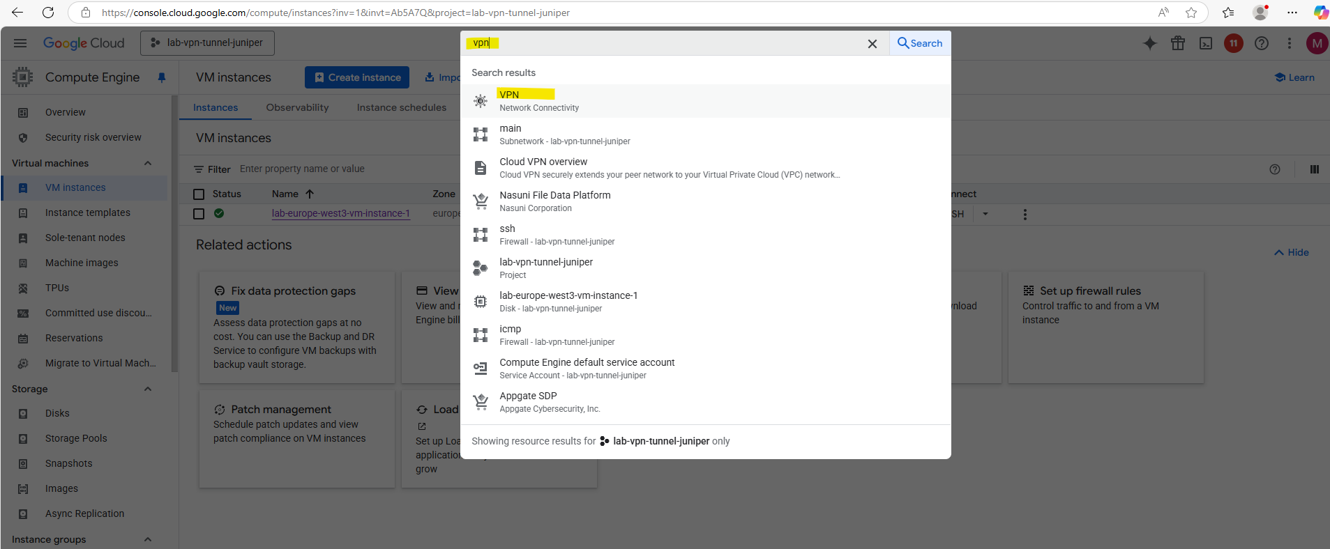
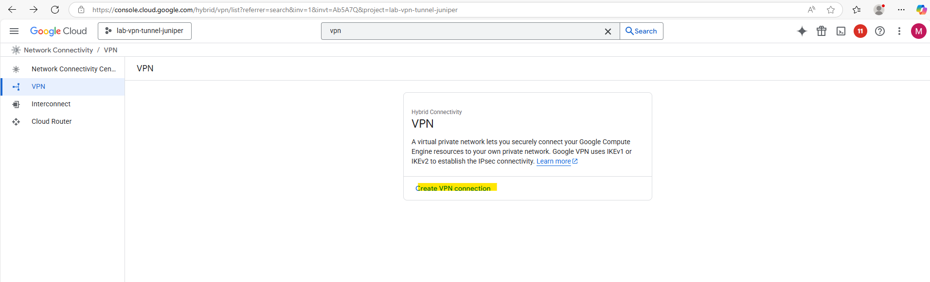
Search for vpn and select below VPN – Network Connectivity.
Click on Create VPN connection.
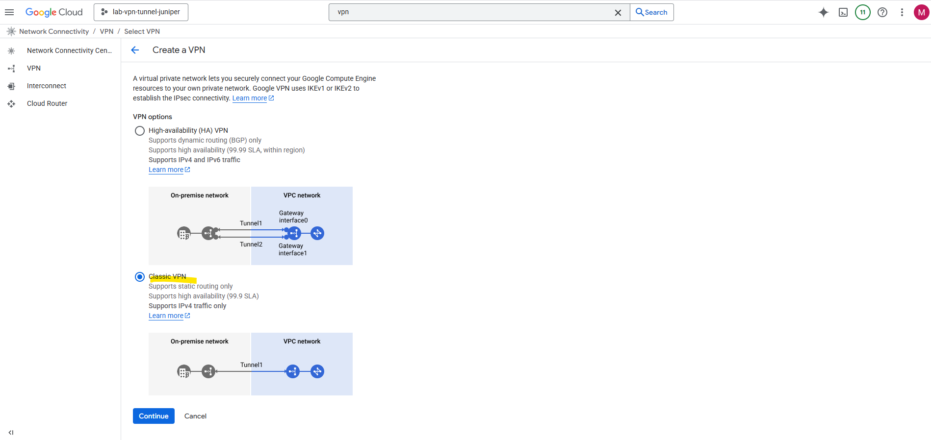
Select Classic VPN.
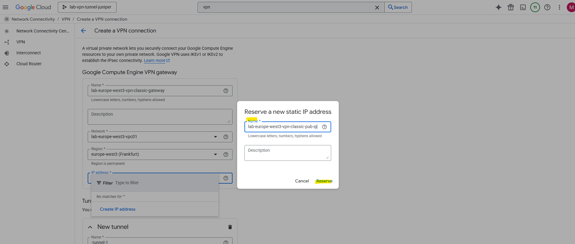
Enter a name for the VPN gateway, the VPC network in which it will be deployed and its region.
Further select an exiting static public IP address or create a new one.
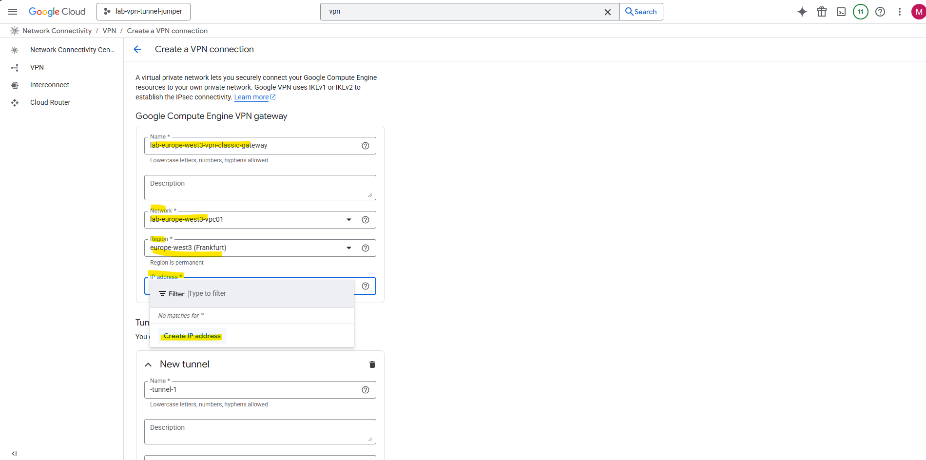
Enter a name for the static public IP and click on Reserve.
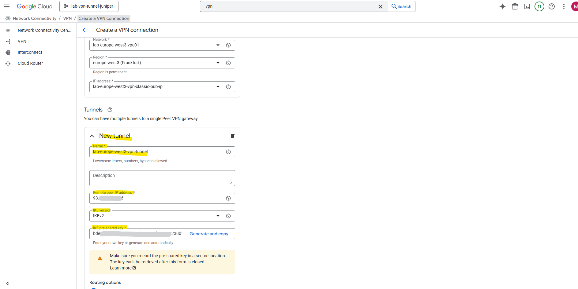
Next also enter the information to create the tunnel. Here enter a name for the tunnel, its region, the public IP address or your on-premise peer (VPN device), the IKE version and the IKE pre shared key.
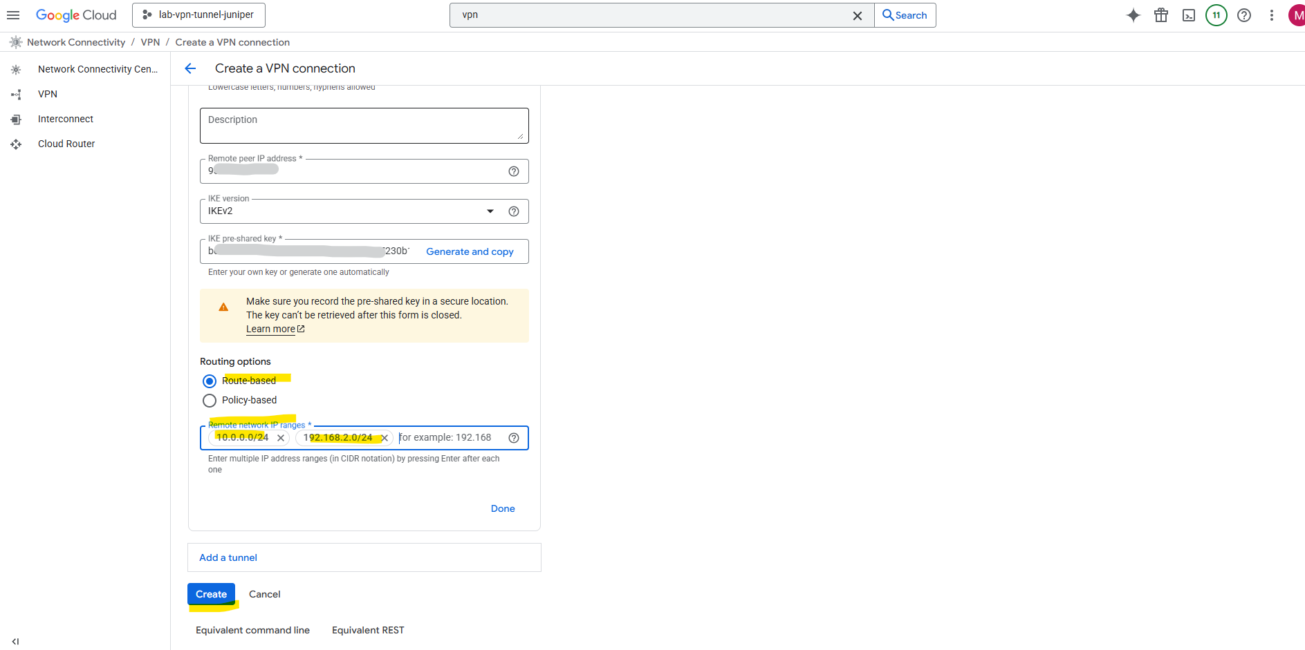
Finally select route-based and enter your local on-premise networks you want route through this tunnel.
We can also create a policy-based IPSec site-to-site VPN here as mentioned to the beginning.
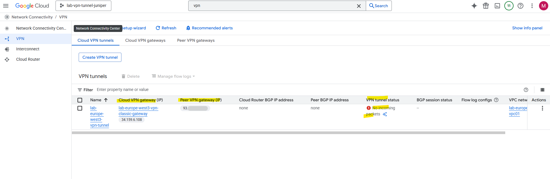
So far we now have created the cloud vpn tunnel and cloud vpn gateway.
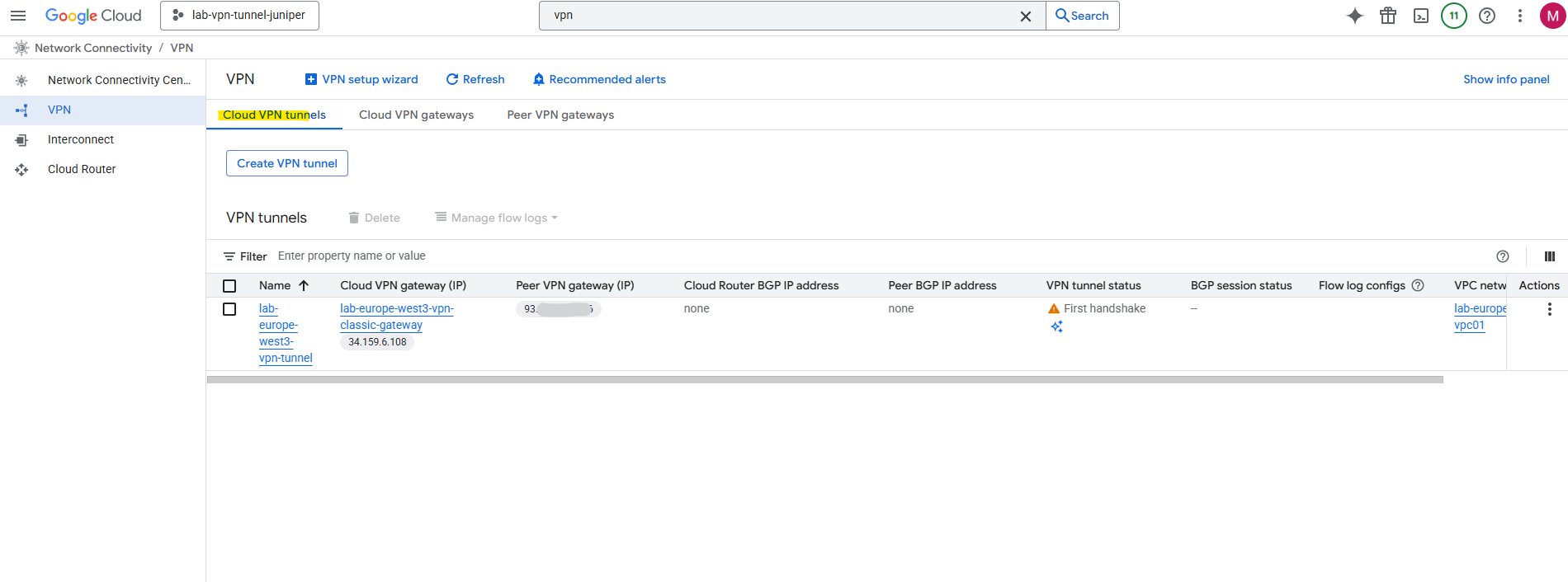
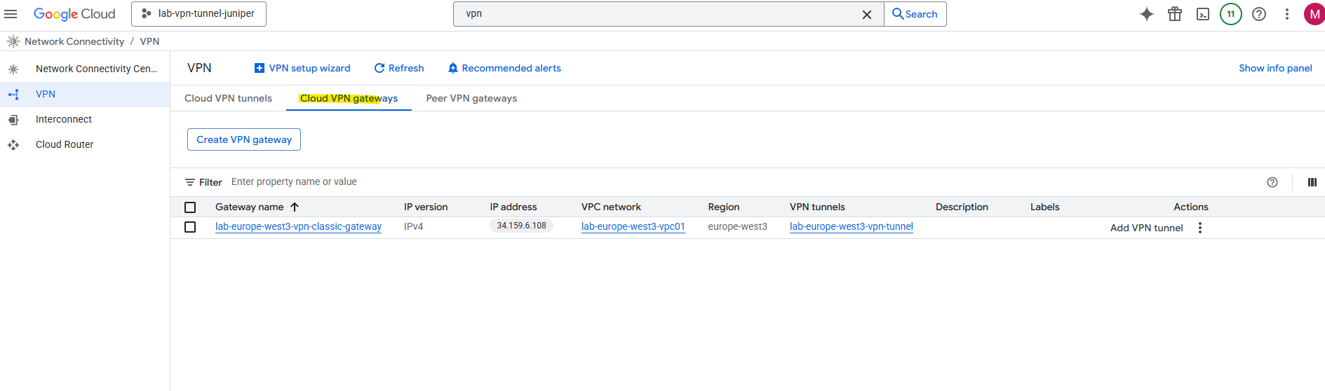
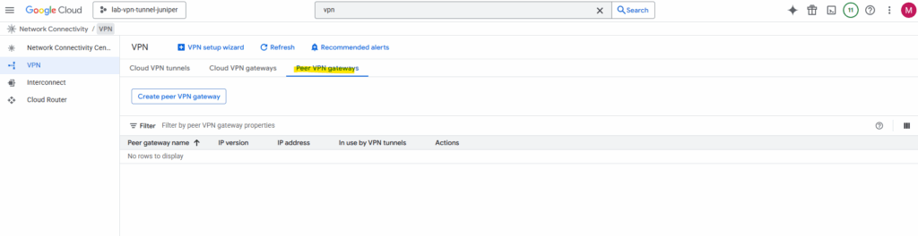
A peer VPN gateway object like for HA VPN is not created here.
In Classic VPN (route-based or policy-based), there is no separate “peer VPN gateway” object in GCP.
You define the peer IP address directly inside the tunnel configuration.
HA VPN introduced the peer VPN gateway object so you can manage multiple tunnels and redundancy in a cleaner, more structured way.So in Classic VPN, the peer info lives inside the tunnel settings, not as a standalone reusable resource.
That’s also why when you edit a Classic VPN tunnel, you directly change the peer IP in that tunnel, while in HA VPN, you change it in the peer VPN gateway object and it applies to all associated tunnels.
Because we so far haven’t configured our on-premise VPN device (the Juniper vSRX appliance), the tunnel of course is still down.
Set up the Tunnel on Juniper by using the CLI
IKE Phase 1 (IKEv2)
We can commit just at the end and don’t need to do this after each section.
set security ike proposal GCP_IKE_PROPOSAL authentication-method pre-shared-keys
set security ike proposal GCP_IKE_PROPOSAL dh-group group14
set security ike proposal GCP_IKE_PROPOSAL authentication-algorithm sha-256
set security ike proposal GCP_IKE_PROPOSAL encryption-algorithm aes-256-cbc
set security ike proposal GCP_IKE_PROPOSAL lifetime-seconds 28800

set security ike policy GCP_IKE_POLICY proposals GCP_IKE_PROPOSAL
set security ike policy GCP_IKE_POLICY reauth-frequency 0

# adjust to your pre-shared key
set security ike policy GCP_IKE_POLICY pre-shared-key ascii-text "<your_psk>"

set security ike gateway GCP_IKE_GATEWAY ike-policy GCP_IKE_POLICY
set security ike gateway GCP_IKE_GATEWAY address <GCP_Public_IP>
set security ike gateway GCP_IKE_GATEWAY no-nat-traversal   ## Important! GCP VPN Gateway sits not behind NAT

# for the local-identiy of Juniper I will use my dynDNS FQDN, usually you will use here the static public IP of your on-premise VPN device
set security ike gateway GCP_IKE_GATEWAY local-identity hostname matrixpost.ddns.net

set security ike gateway GCP_IKE_GATEWAY remote-identity inet <GCP_Public_IP>
set security ike gateway GCP_IKE_GATEWAY external-interface ge-0/0/1.0
set security ike gateway GCP_IKE_GATEWAY version v2-only
IPSec Phase 2
set security ipsec proposal GCP_IPSEC_PROPOSAL protocol esp
set security ipsec proposal GCP_IPSEC_PROPOSAL authentication-algorithm hmac-sha-256-128
set security ipsec proposal GCP_IPSEC_PROPOSAL encryption-algorithm aes-256-cbc
set security ipsec proposal GCP_IPSEC_PROPOSAL lifetime-seconds 28800

set security ipsec policy GCP_IPSEC_POLICY proposals GCP_IPSEC_PROPOSAL

set security ipsec vpn GCP_VPN bind-interface st0.0
set security ipsec vpn GCP_VPN ike gateway GCP_IKE_GATEWAY
set security ipsec vpn GCP_VPN ike ipsec-policy GCP_IPSEC_POLICY
set security ipsec vpn GCP_VPN establish-tunnels immediately
Interface & Routing
Classic VPN + static routing: GCP does not expose/require an inside /30 subnet for its virtual tunnel interface.
On your Juniper we can pick any /30 (APIPA is common), because GCP matches Phase-2 by traffic selectors (proxy-IDs), not by the tunnel interface IP.
We can also leave st0.0 just unnumbered; many folks still assign an APIPA /30 for clarity.
In a route-based IPsec VPN, our traffic is selected by routes via the st0.x interface bound to our IPsec Security Association (SA).
The SA already defines the secure “pipe” between the two peers based on Phase 2 settings (SPI, encryption, authentication).
When we run on Juniper the command set routing-options static route 172.17.0.0/16 next-hop st0.0 to set the static route for the Azure virtual network, Junos doesn’t send packets to an IP, it sends them to the interface.
The forwarding engine sees that interface is mapped to an active IPsec SA and encapsulates the packets directly into ESP for the remote peer.
Because it’s all handled at Layer 3→ Layer 4 encapsulation, no Layer 3 address on the tunnel itself is required unless you’re running a routing protocol (BGP/OSPF).
For BGP/OSPF in contrast, we need to assign IP addresses to the tunnel interfaces on both sides because BGP/OSPF is based on Layer 3 reachability between the two peers. BGP is a routing protocol that needs to form a TCP session (TCP port 179) between two IP addresses.
This means the VPN tunnel must have an addressable /30 or /31 network that exists only for the purpose of BGP transport, sometimes called the BGP peer network.
# e.g. assign an APIPA /30 subnet or as mentioned leave it unnumbered and skip set interfaces command (virtual tunnel interface)
set interfaces st0 unit 0 family inet address 169.254.14.246/30

# add a static routing for your GCP subnet
set routing-options static route 172.17.10.0/24 next-hop st0.0
When Junos OS looks up a route to find the interface to use to send traffic to the packet’s destination address, it finds a route through a secure tunnel interface (st0.x). The tunnel interface is bound to a specific VPN tunnel, and the traffic is routed to the tunnel if the policy action is permit.
Security Zones
set security zones security-zone vpn interfaces st0.0
set security zones security-zone trust interfaces ge-0/0/0.0
set security zones security-zone untrust interfaces ge-0/0/1.0
set security zones security-zone untrust screen untrust-screen
Security Policies
# Trust → VPN
set security policies from-zone trust to-zone vpn policy trust-to-azure match source-address any
set security policies from-zone trust to-zone vpn policy trust-to-azure match destination-address any
set security policies from-zone trust to-zone vpn policy trust-to-azure match application any
set security policies from-zone trust to-zone vpn policy trust-to-azure then permit

# VPN → Trust
set security policies from-zone vpn to-zone trust policy azure-to-trust match source-address any
set security policies from-zone vpn to-zone trust policy azure-to-trust match destination-address any
set security policies from-zone vpn to-zone trust policy azure-to-trust match application any
set security policies from-zone vpn to-zone trust policy azure-to-trust then permit
Logging & Debugging (optional but useful)
set system syslog file ike-log any any
set system syslog file ike-log match invalid
set security ike traceoptions file ike-debug
set security ike traceoptions file size 1m
set security ike traceoptions file files 5
set security ike traceoptions flag all
As already mentioned, finally we need to commit our new configuration.
root@junos-vsrx3# commit
Special Notes
Firewall policies are wide open between zones. You may want to restrict these for production.
Verify if the Tunnel is up and Routing works
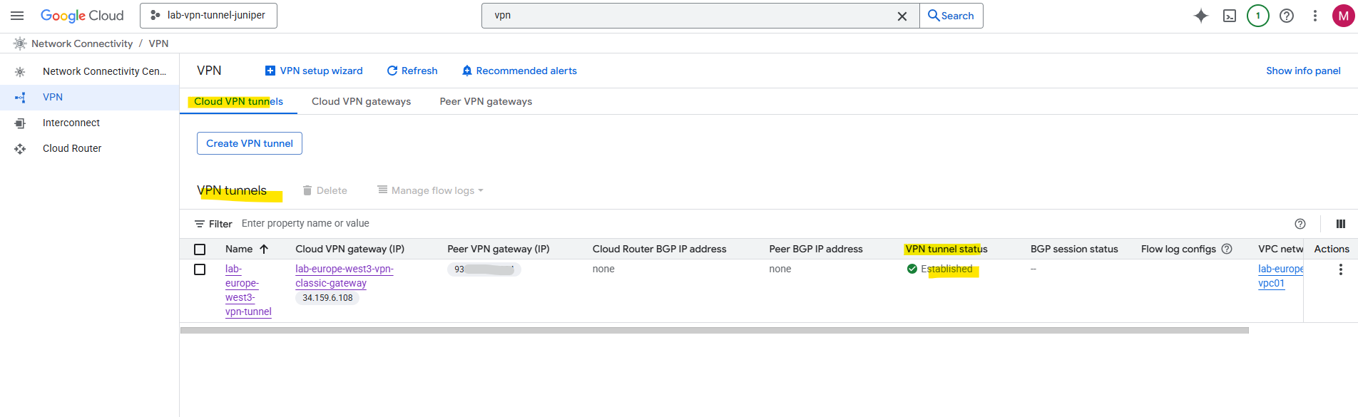
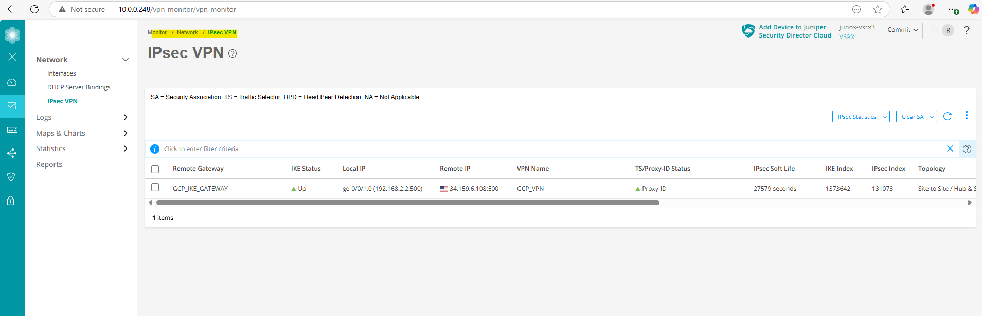
After running the commit command on Juniper above to apply the tunnel configuration, the tunnel between Juniper and GCP was immediately established.
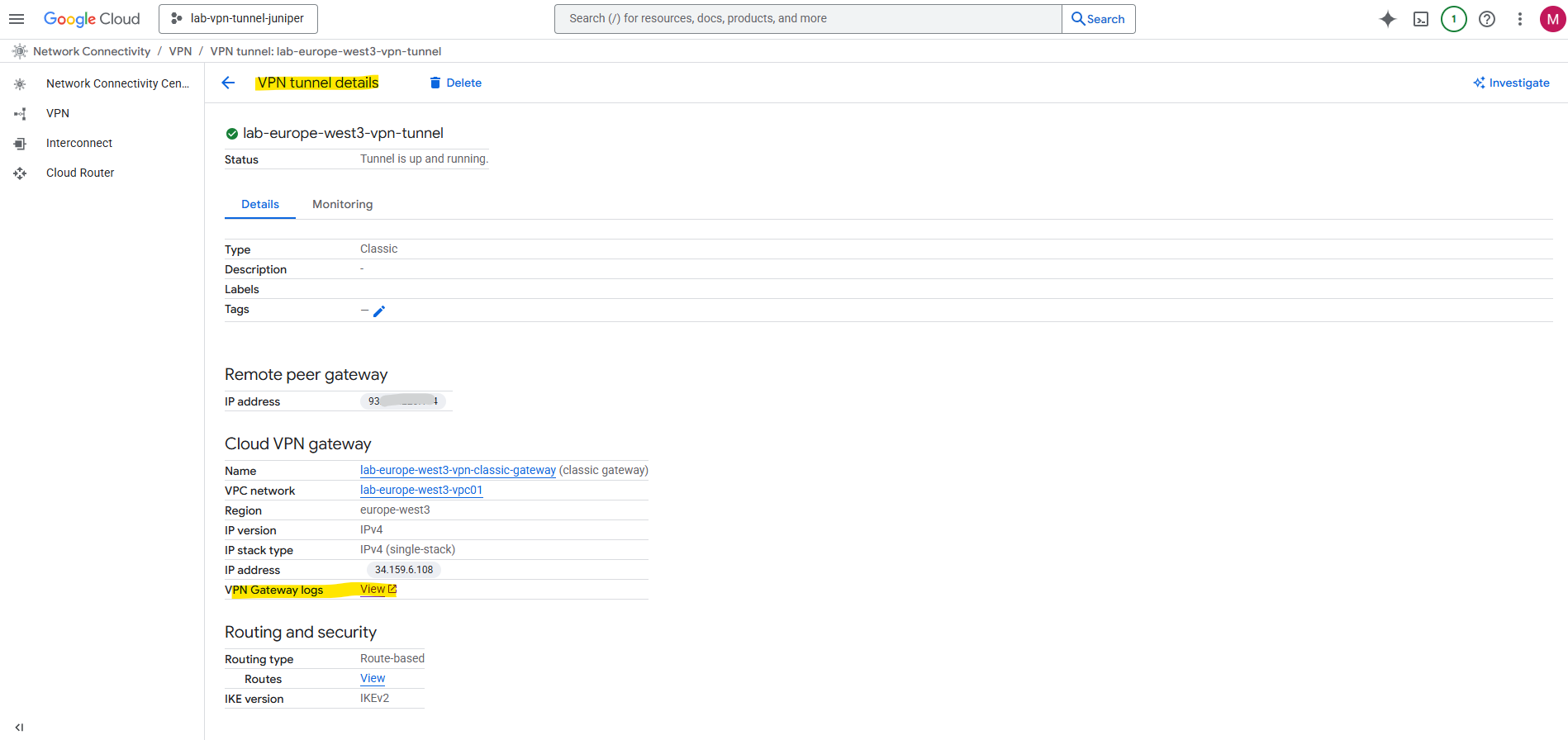
On the VPN tunnel details we can also check the VPN Gateway logs in case the tunnel isn’t coming up as expected to analyze the logs and see the negotiation of phase 1 and phase 2 between both peers.
Because both phase 1 (IKE) and phase 2 (IPSec/EPS) are already established, we can see in the log below that already traffic is routed through the tunnel.
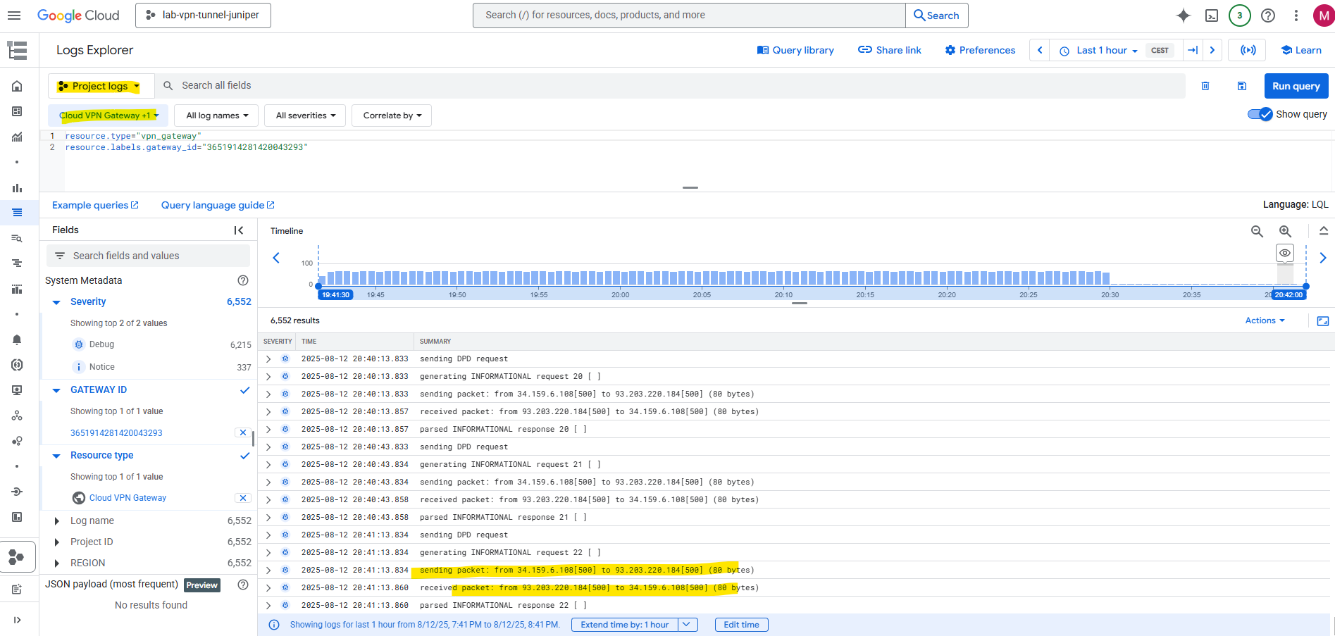
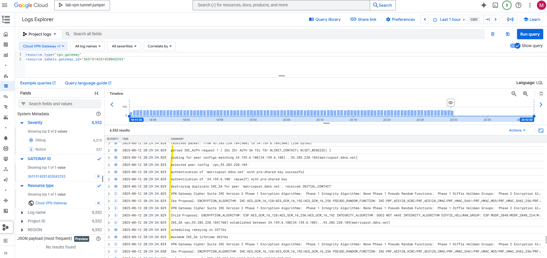
When scrolling back we can also see the negotiation of the tunnel was logged between both peers here.
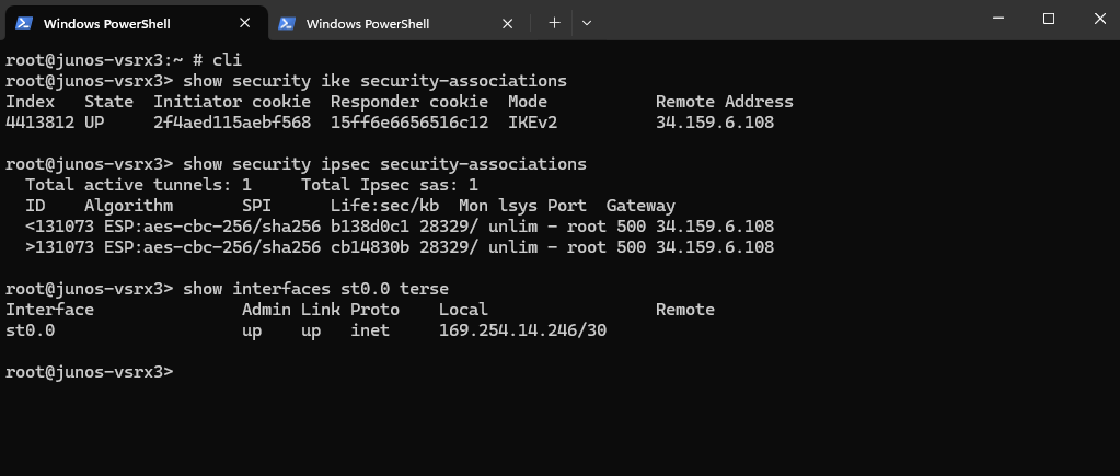
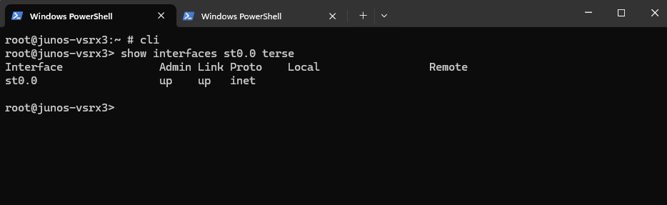
On Juniper we can run the following commands to check if phase 1 (IKE) and phase 2 (IPSec) is up.
root@junos-vsrx3> show security ike security-associations
root@junos-vsrx3> show security ipsec security-associations

We can also check if the tunnel interface is up
root@junos-vsrx3> show interfaces st0.0 terse
In case we will leave st0.0 just unnumbered as mentioned further above and not required for static routing without BGP, the Local IP address is missing.
Check if the tunnel interface is up
root@junos-vsrx3> show interfaces st0.0 terse
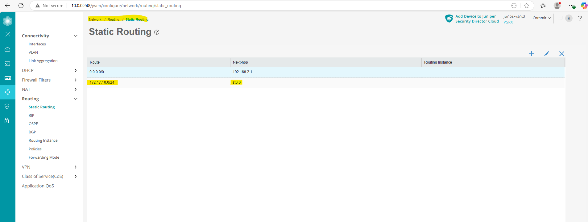
On the Web UI we can also check if the tunnel is up.
And under static routing we will see our tunnel interface st0.0 (unnumbered) which is the next hop for my GCP subnet 172.17.10.0/24.
More about troubleshooting on Juniper you will find in my following post.
Links
Classic VPN dynamic routing deprecation
https://cloud.google.com/network-connectivity/docs/vpn/deprecations/classic-vpn-deprecation?utm_source=chatgpt.comRoute-Based IPsec VPNs
https://www.juniper.net/documentation/us/en/software/junos/vpn-ipsec/topics/topic-map/security-route-based-ipsec-vpns.htmlNetworks and tunnel routing
https://cloud.google.com/network-connectivity/docs/vpn/concepts/choosing-networks-routingAbout Hybrid Subnets
https://cloud.google.com/vpc/docs/hybrid-subnetsSupported IKE ciphers
https://cloud.google.com/network-connectivity/docs/vpn/concepts/supported-ike-ciphersSRX Series Firewalls
https://www.juniper.net/us/en/products/security/srx-series.htmlJuniper Licensing User Guide
https://www.juniper.net/documentation/us/en/software/license/juniper-licensing-user-guide/index.htmlvSRX Deployment Guide for VMware
https://www.juniper.net/documentation/us/en/software/vsrx/vsrx-vmware/vsrx-vmware.pdfvSRX Virtual Firewall User Guide for Private and Public Cloud Platforms
https://www.juniper.net/documentation/us/en/software/vsrx/vsrx-consolidated-user-guide/vsrx-consolidated-user-guide.pdfAdd vSRX Virtual Firewall Interfaces
https://www.juniper.net/documentation/us/en/software/vsrx/vsrx-consolidated-deployment-guide/vsrx-vmware/topics/task/security-vsrx-vmware-adding-interfaces-update.htmlUser Access and Authentication Administration Guide for Junos OS
https://www.juniper.net/documentation/us/en/software/junos/user-access/topics/topic-map/user-access-root-password.htmlJuniper vSRX Setup & Initial Configuration Guide
https://journey2theccie.wordpress.com/2021/02/04/juniper-vsrx-setup-initial-configuration-guide/Security Zones
https://www.juniper.net/documentation/us/en/software/junos/security-policies/topics/topic-map/security-zone-configuration.htmlsystem-services (Security Zones Host Inbound Traffic)
https://www.juniper.net/documentation/us/en/software/junos/cli-reference/topics/ref/statement/security-edit-system-service-zone-host-inbound-traffic.htmlExample: Configuring NAT for vSRX Virtual Firewall
https://www.juniper.net/documentation/us/en/software/vsrx/vsrx-consolidated-deployment-guide/vsrx-aws/topics/example/security-vsrx-example-aws-nat.htmlMonitor Log Messages
https://www.juniper.net/documentation/us/en/software/junos/network-mgmt/topics/topic-map/displaying-and-interpreting-system-log-message-descriptions.html