Step-by-Step Guide: Setting up Route Based S2S VPN between Azure and on-prem by using pfSense – Part 1
Establishing a secure and reliable VPN tunnel between your on-premises network and Azure is a critical step in enabling hybrid cloud scenarios. In this two-part guide, we will see step by step setting up a site-to-site IPsec VPN using pfSense on the on-prem side and Azure VPN Gateway in the cloud.
The first part covers the setup using static routes, ideal for simpler environments or when dynamic routing isn’t required. The second part explores BGP (Border Gateway Protocol) to enable dynamic route exchange, which is better suited for larger or more complex networks.
In both scenarios, we will see two approaches regarding IP addresses used for the tunnel interfaces of IPSec/EPS phase 2 tunnel.
- Using the default immutable BGP IP address from Azure’s VPN Gateway Subnet
- Using APIPA (Automatic Private IP Addressing) addresses (169.254.x.x) for BGP peering, which offers more flexibility in network design
pfSense blocks APIPA traffic by default for security reasons.
To use APIPA-based transit networks successfully on pfSense, we must first enable APIPA traffic in the advanced system settings or by applying a short PHP command to disable the default block rule.
More about in my following post https://blog.matrixpost.net/pfsense-and-apipa-169-254-16-enabling-link-local-transit-networks-for-ipsec-vti-and-bgp/.
Set up the Tunnel in Azure
About how to set up the tunnel in Azure step by step you can read in one of my previous posts here, where I was also first creating a new virtual network which finally should be connected with my on-prem lab network and environment.
In that post I was also enabling and configuring BGP in Azure, so below I will just show the different configuration in Azure when using static routes in contrast.
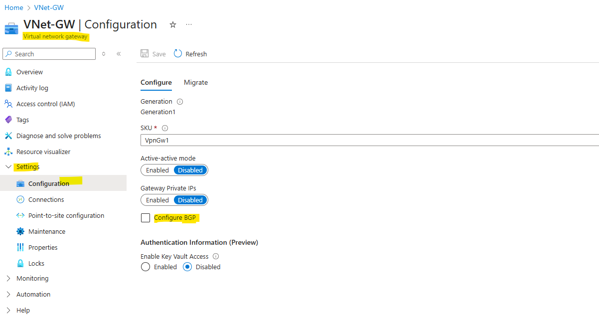
So by using static routes, we doesn’t configure and enable BGP in Azure. As I want to use to show the configuration here my still existing Virtual network gateway where BGP is already enabled, I will first have to disable it.
To disable it afterwards completely in Azure, I will first uncheck Configure BGP on the Virtual network gateway settings as shown below.
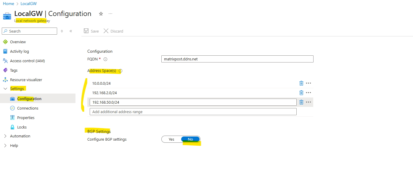
We also need to disable it on the Local network gateway object as shown below, further because we disable it here, we also need to enter our desired local on-prem networks we want to route through the tunnel here under Address Space(s).
During the creation of the local network gateway object, I was selecting to use FQDN for the on-prem VPN device, because for my home lab network, unfortunately I don’t have a static public IP address assigned to my NAT router and have to use dynDNS, so usually you will configure here a static public IP address.
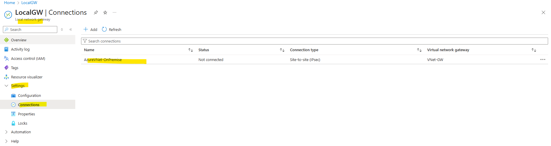
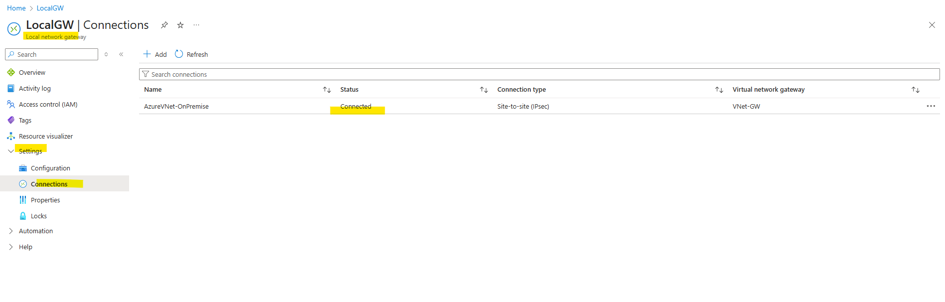
And finally we also need to disable BGP on the connection object in Azure. Therefore we can either open the connection through the Local network gateway or Virtual network gateway object, either will have the Settings -> Connections menu. Click on the connection.
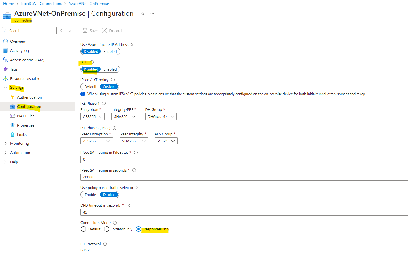
Toggle BGP to Disabled and save the connection.
Here you can see by the way also that I set the connection in Azure as ResponderOnly, the reason for is that in my home lab network I will use a NAT router (FRITZ!Box) in front of my VPN device (pfSense).
So because of this I have to use NAT-Traversal (NAT-T) here, I just want pfSense to initiating the VPN tunnel, otherwise I would also have to publish and forward the ports UDP 500 (ISAKMP) and 4500 (NAT traversal) on my NAT router (FRITZ!Box) and forward them to pfSense.
GCP for example unfortunately does not provide a setting equivalent to Azure’s responder-only mode. You cannot force it to only respond. More about in my following post.
So that’s all on Azure side, next I will show step by step how to set up the tunnel in pfSense by using static routing.
Set up the Tunnel in pfSense
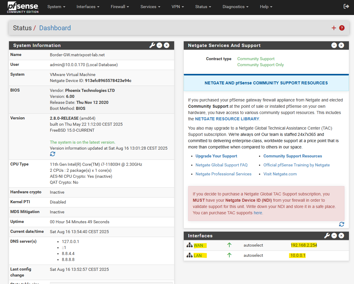
As already mentioned, my pfSense appliance sits behind my NAT router (FRITZ!Box), therefore its external WAN interface have a private IP address assigned to by the subnet in which also FRITZ!Box‘s internal interface (IP 192.168.2.1) is connected to.
The internal LAN interface with the IP address 10.0.0.1 is connected to my internal network 10.0.0.0/24.
For static routing we finally just need these two interfaces to set up the tunnel, in my next post when enabling BGP to advertise routes between both peers (on-prem and Azure), we need another so called tunnel interface or VTI (virtual tunnel interface) to set up the IPsec/EPS phase 2 tunnel.
Create Phase 1 Tunnel
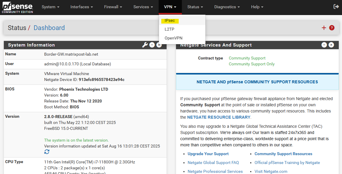
To create a new tunnel navigate to VPN -> IPsec.
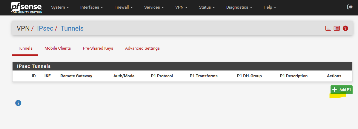
Click on + Add P1 to create a new IKE phase 1 tunnel.
Below we need to enter a description for the tunnel, the public IP address of Azure’s VPN gateway under Remote Gateway and the pre-shared key we want to use to authenticate to each other. We can also let pfSense to generate a key, finally on both sides this key must match.
The rest we can leave on its default setting and is fine.
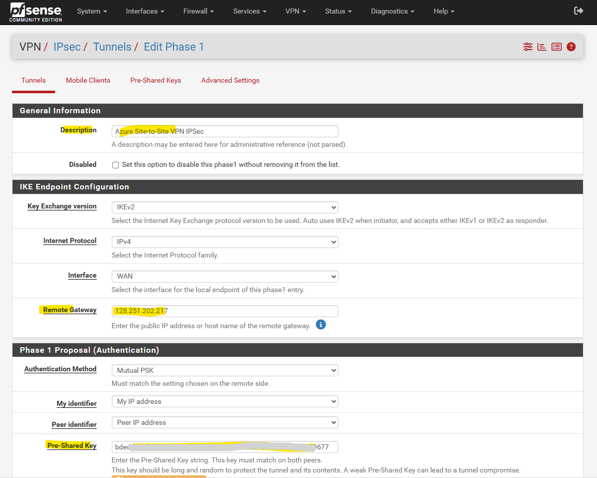
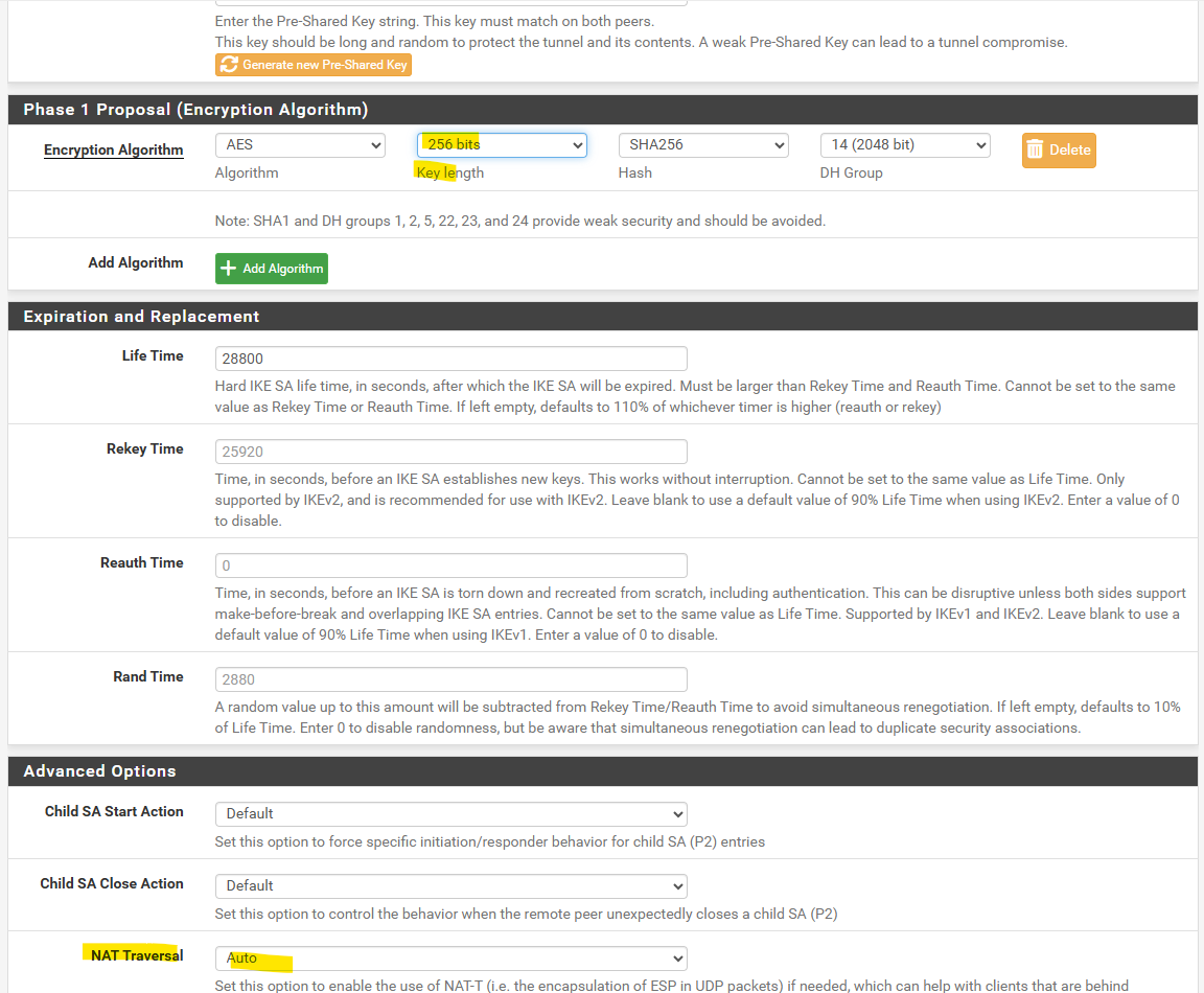
The phase 1 IKE proposal for encryption, integrity and the Diffie–Hellman group I will leave also on pfSense’s suggested default settings.
I will just change the key length to 256 bits. Finally they must match with Azure’s.
As mentioned pfSense sits behind my NAT router (FRITZ!Box), we can leave the NAT Traversal settings on Auto and pfSense will determine by default it have to use NAT-T.
pfSense starts IKE on UDP 500, exchanges NAT-D payloads, and if NAT is detected, it transparently switches to UDP 4500 (NAT-T) so ESP traffic can pass through the NAT device.
When a VPN device like pfSense starts IKE negotiation, it begins with UDP 500 (IKE). During the exchange, the peers include NAT-Discovery (NAT-D) payloads, basically hashes of their source/destination IPs and ports.
- If both sides see the hashes match → no NAT detected → continue on UDP 500.
- If there’s a mismatch → at least one peer is behind NAT. Both sides then automatically switch the negotiation and ESP traffic into UDP 4500 (NAT-Traversal / NAT-T), where the ESP packets are wrapped in UDP headers so NAT devices can track the session correctly.
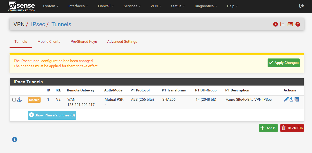
The rest we can all leave on its default settings, finally click on Save and we’re done with our phase 1 tunnel.
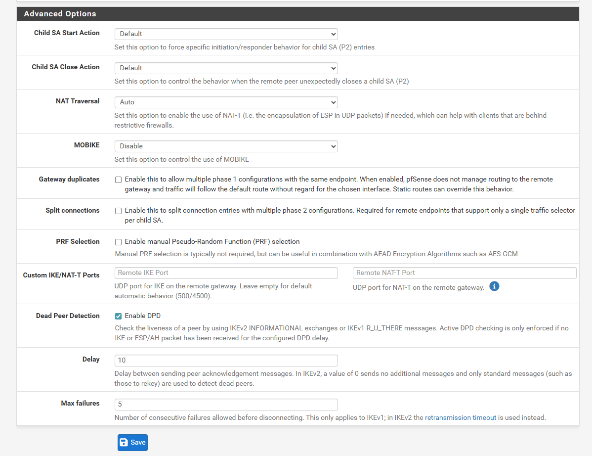
Click on Apply Changes.
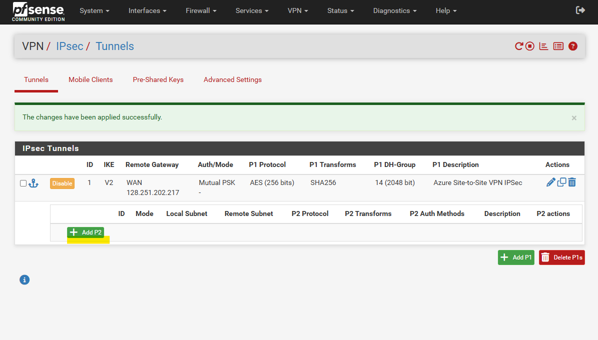
Create Phase 2 Tunnel
Now to also add our IPSec/EPS phase 2 tunnel, click on + Add P2 below.
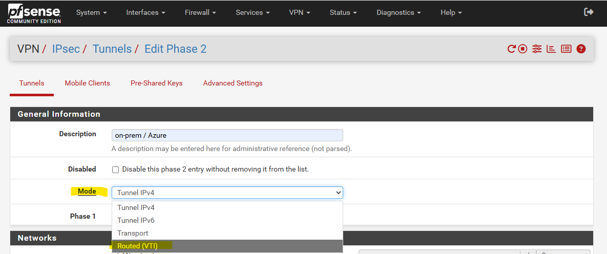
First enter a description for phase 2 and then choose the Mode.
By default Tunnel IPv4 is pre-selected, this is the default / traditional IPsec mode and used for policy-based VPNs. For policy-based VPNs in pfSense you need to configure for each source subnet you want to route/connect to a specific destination subnet a dedicated phase 2 tunnel.
Because we want to set up a route-based VPN, we need to select for the Mode here Routed VTI.
Here pfSense builds a virtual interface to which we need to assign an IP address (often APIPA like 169.254.x.x/30). The tunnel itself carries traffic like a normal interface, pfSense no longer relies on Phase 2 network definitions to match traffic. Finally all subnets can be routed through this tunnel interface and we just need exactly one phase 2 tunnel which is also called transit network.
The tunnel interface finally is bound to our IPsec Security Association (SA).
Transport mode ==> used mostly for end-to-end host-to-host protection, not network-to-network.
When selecting Routed VTI as mentioned pfSense builds a virtual interface to which we need to assign an IP address.
For the local network and remote network we need to select Network below, but IP addresses do we finally need to enter for both?
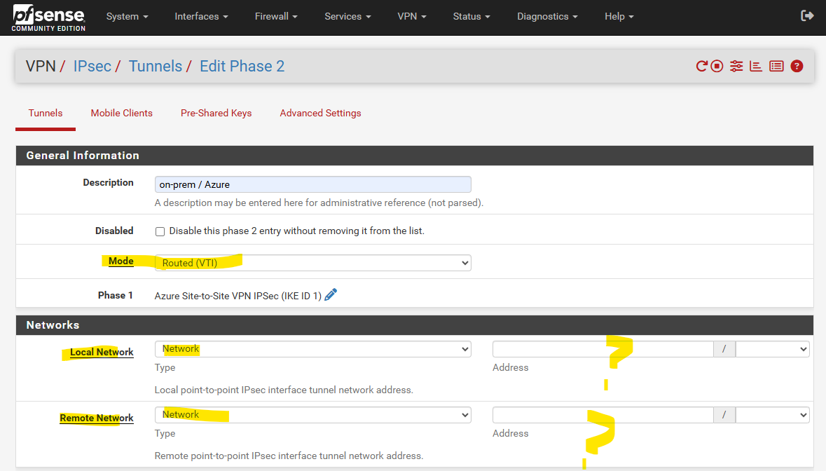
Actually for a route-based VPNs they use static routes, many firewall and route platforms (like Juniper, Cisco, Check Point, etc.), the tunnel interfaces can be left unnumbered and no need to assign IP addresses here.
In my following post for example I was set up a route based VPN tunnel by using also static routes and leaving the tunnel interface also unnumbered.
pfSense, however is different and requires numbered interfaces. Each tunnel must have an IP address on both ends (commonly a /30 or /31 private address range subnet ). Without this, pfSense won’t allow you to install static routes over the tunnel.
You can either use the BGP peer IP address /30 subnet allocated by Azure’s VPN gateway subnet, no matter if BGP is enabled or not, or you can assign as mentioned an APIPA /30 or /31 like 169.254.x.x.
When using link-local APIPA addresses on pfSense, we must first enable them on pfSense as mentioned to the beginning and shown in my following post https://blog.matrixpost.net/pfsense-and-apipa-169-254-16-enabling-link-local-transit-networks-for-ipsec-vti-and-bgp/.
!! Note !!
In case we want to set up BGP instead static routes, Azure just supports BGP IP in the ranges 169.254.21.* and 169.254.22.*. as shown in my following post.But for static routes this doesn’t matter and Azure anyway don’t care about the IP address we configure on pfsense here.
A common way is to use here the BGP peer IP address /30 subnet even when BGP is not enabled. To determine this IP we can just temporarily check Configure BGP on the virtual network gateway in Azure.
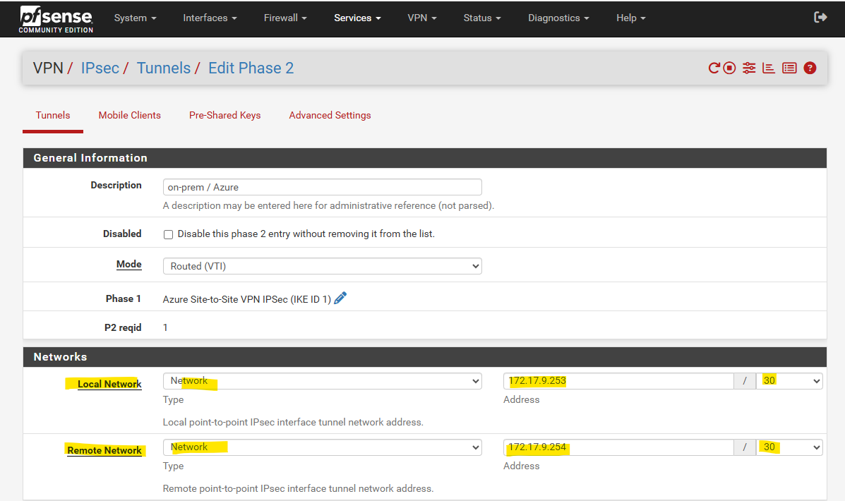
Azure is using here for the BGP peer IP 172.17.9.254, finally its a /30 subnet allocated from the VPN gatway subnet in Azure.
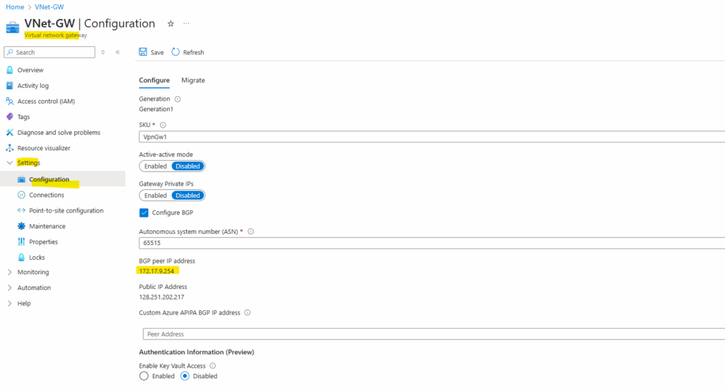
So the counterpart or second usable IP address of this /30 subnet is 172.17.9.253 which we can use on pfSense’s virtual tunnel interface (VTI) and need to enter below in the local network field as highligted.
But as already mentioned, finally we could also use here APIPA addresses like 169.254.10.1/32 and 169.254.10.2/32. Azure don’t care about because also supports unnumbered tunnel interfaces when static routes configured and BGP is not enabled.
These unnumbered interfaces works because the forwarding engine (IPsec processing path) sees that interface is mapped to an active IPsec SA and encapsulates the packets directly into ESP for the remote peer. More about in my following post.
Next we need to adjust the phase 2 proposal.
Finally they must match with Azure’s again.
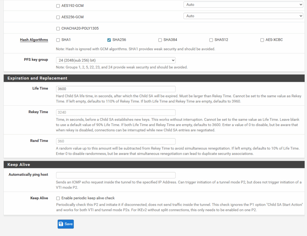
In IPsec Phase 2, the PFS group refers to the Perfect Forward Secrecy (PFS) Diffie–Hellman group. The Diffie–Hellman group used for additional key exchange during IPsec SA establishment.
It enforces that each Phase 2 rekey has unique key material, even if the Phase 1 SA remains unchanged. It’s a security hardening step, ensures forward secrecy (past traffic stays secure even if long-term keys are later compromised).
Without PFS → still secure, but less resilient (keys chained to Phase 1).
With PFS → more computational overhead, but stronger long-term security.
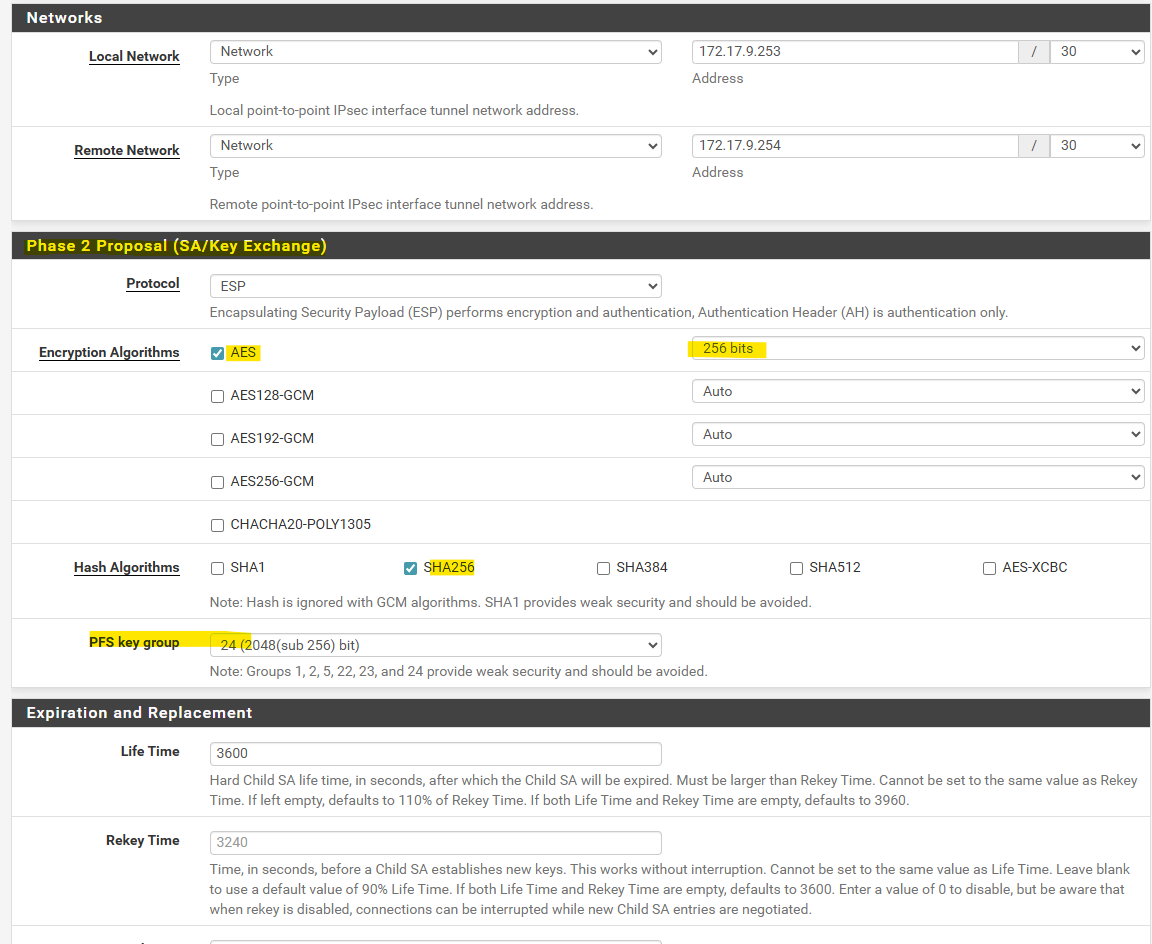
The rest I leave on its default settings and we can click on Save.
Assign the Tunnel Interface (VTI)
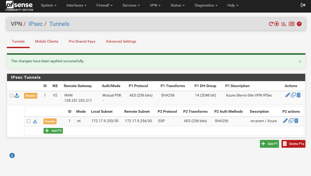
As mentioned when selecting on phase 2 for the Mode Routed VTI, pfSense creates a virtual interface to which finally automatically the IP address we set previously for the local subnet on phase 2 is set.
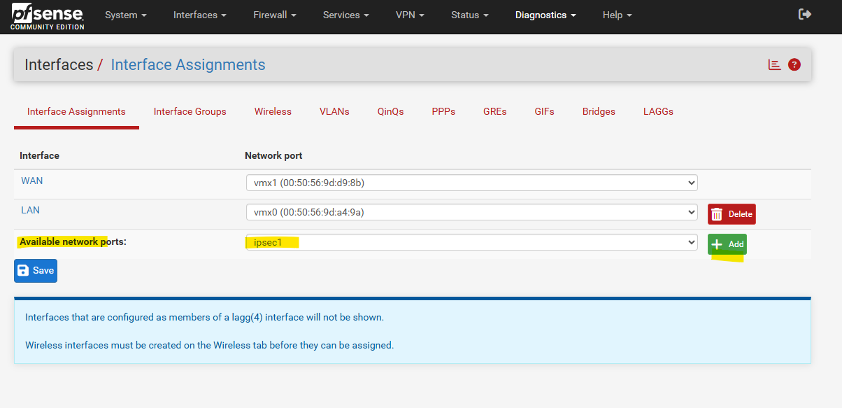
The only step we need to perform is to finally assign this interface to pfSense to enable it. So under Interfaces click on Assignments as shown below.
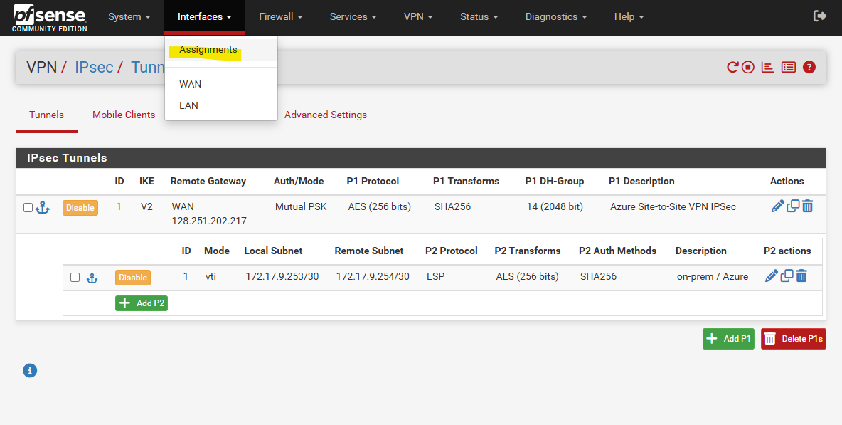
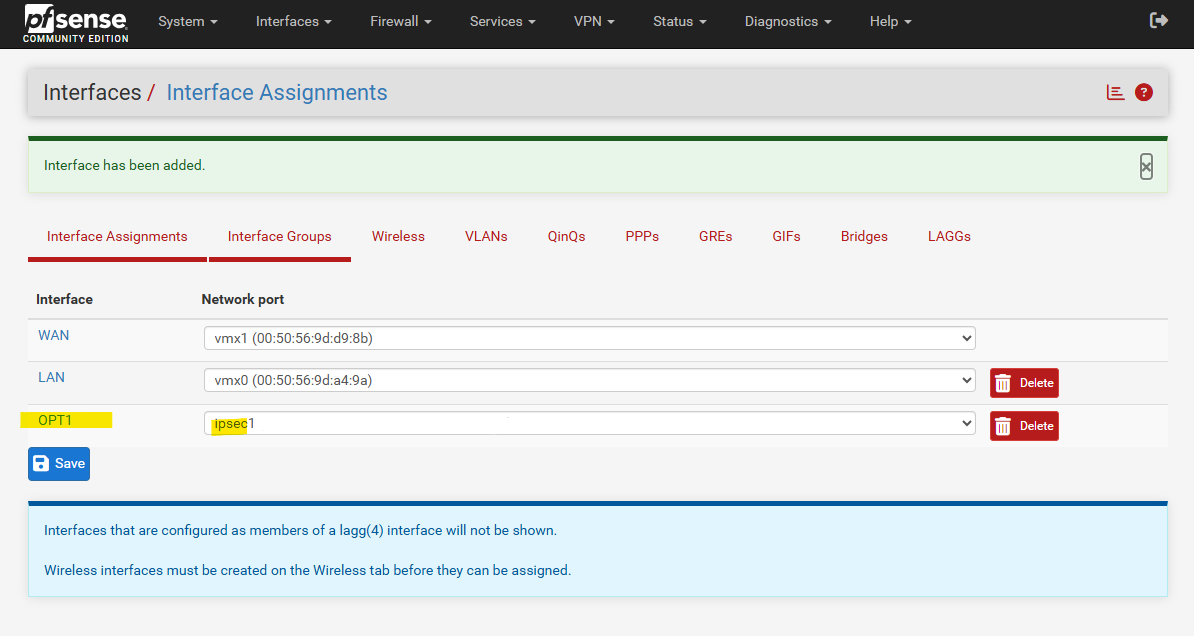
Under available network ports the new tunnel interface (VTI) should shown up, click on + Add.
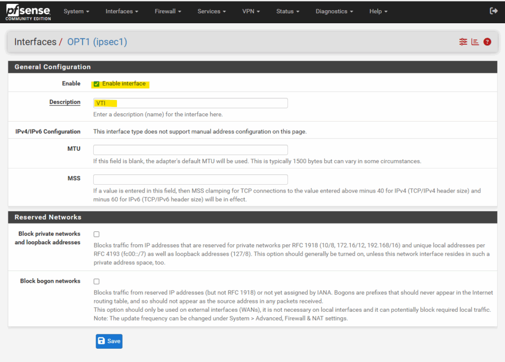
For the name by default OPT1 is set by pfSense, to rename it just click on it.
Enter a desired name like VTI and check Enable interface. Finally click on Save.
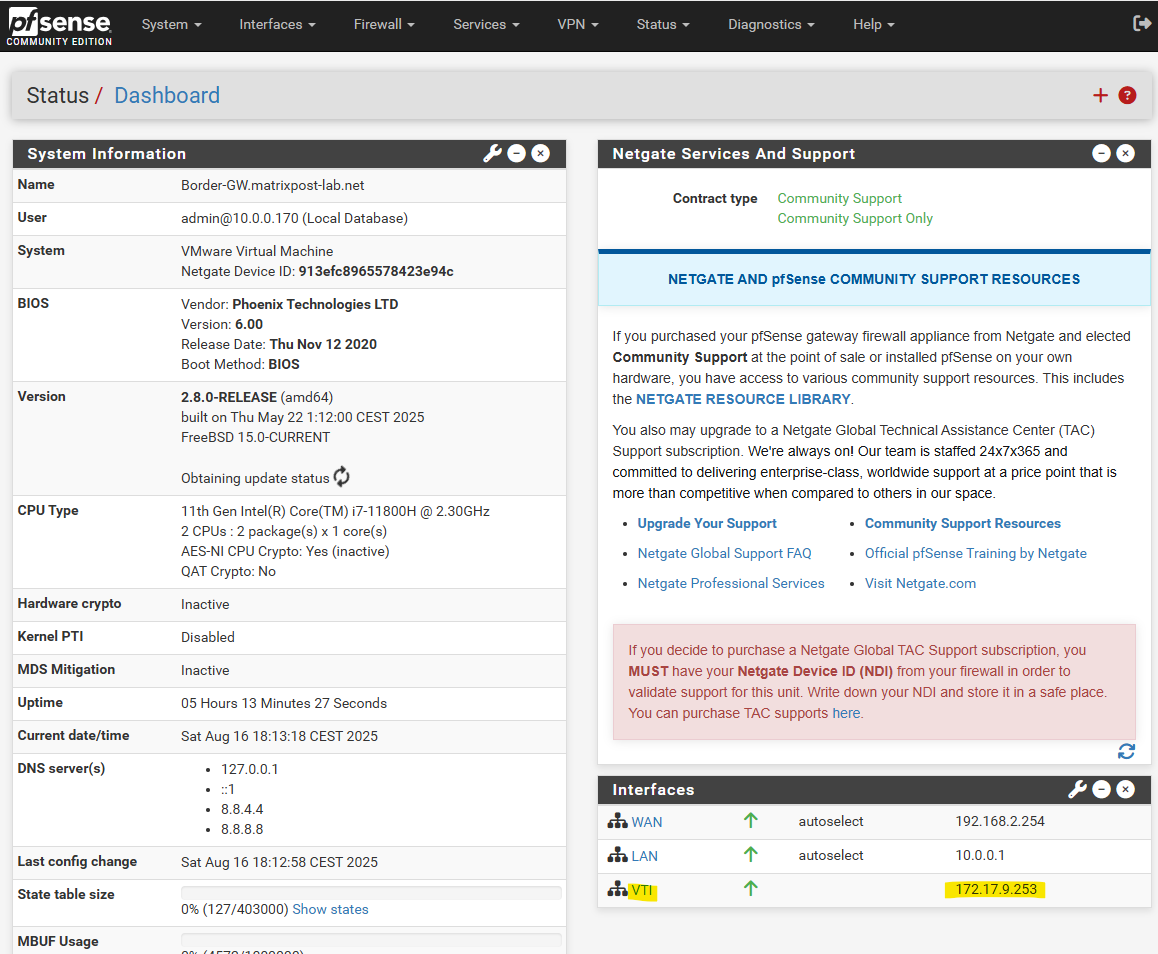
When you navigate to the dashboard you can already see that automatically our previously assigned 172.17.9.253 IP address from the phase 2 local network field is assigned to.
Configure Static Routes
The tunnel itself now should already be able to be established but one last step we need to configure in order traffic can be routed successfully between our on-prem and Azure network.
We finally also need to configure on pfSense a static route for our Azure virtual network 172.17.0.0/16.
Therefore on pfSense navigate to System -> Routing.
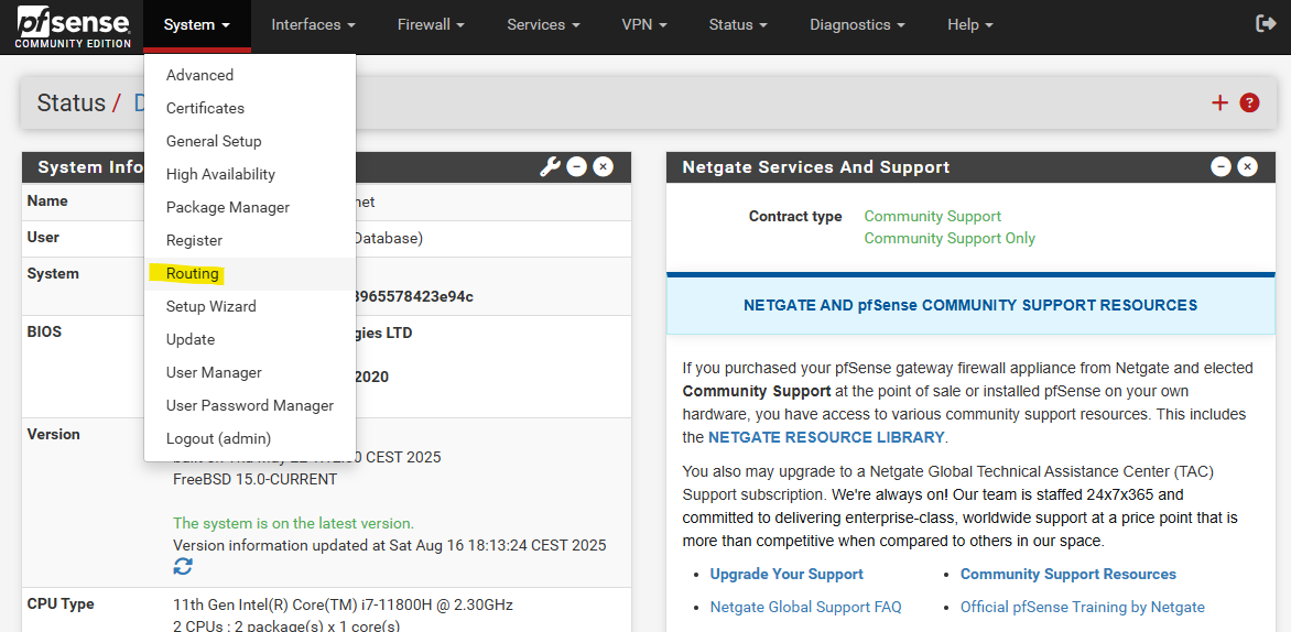
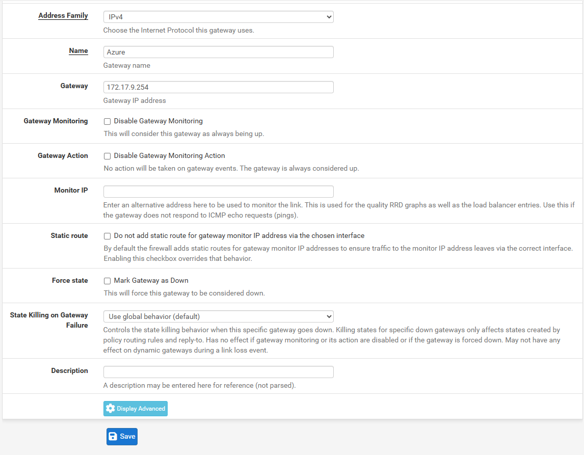
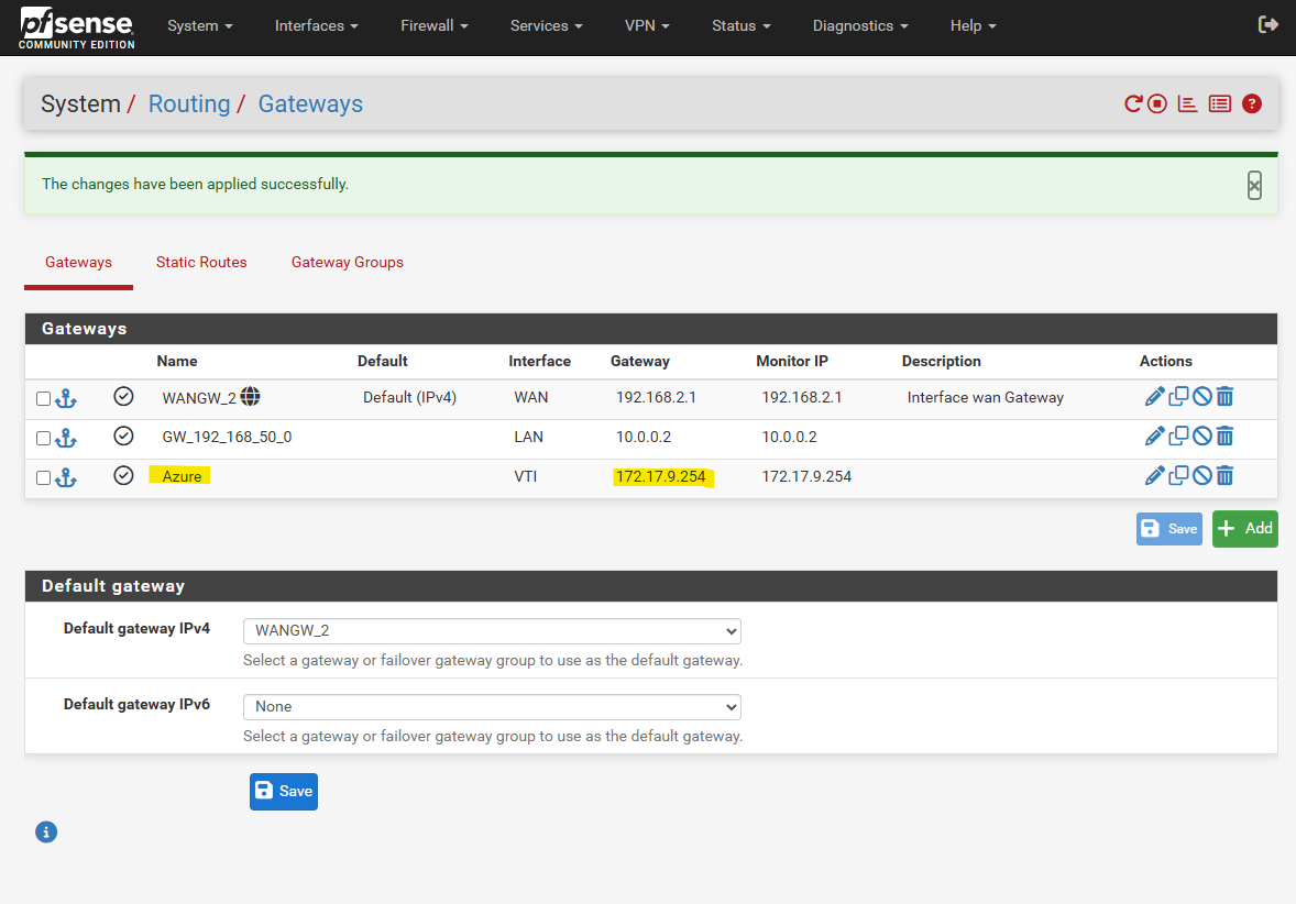
Here we first need to add our newly create tunnel interface (VTI) as new gateway.
Click on + Add.
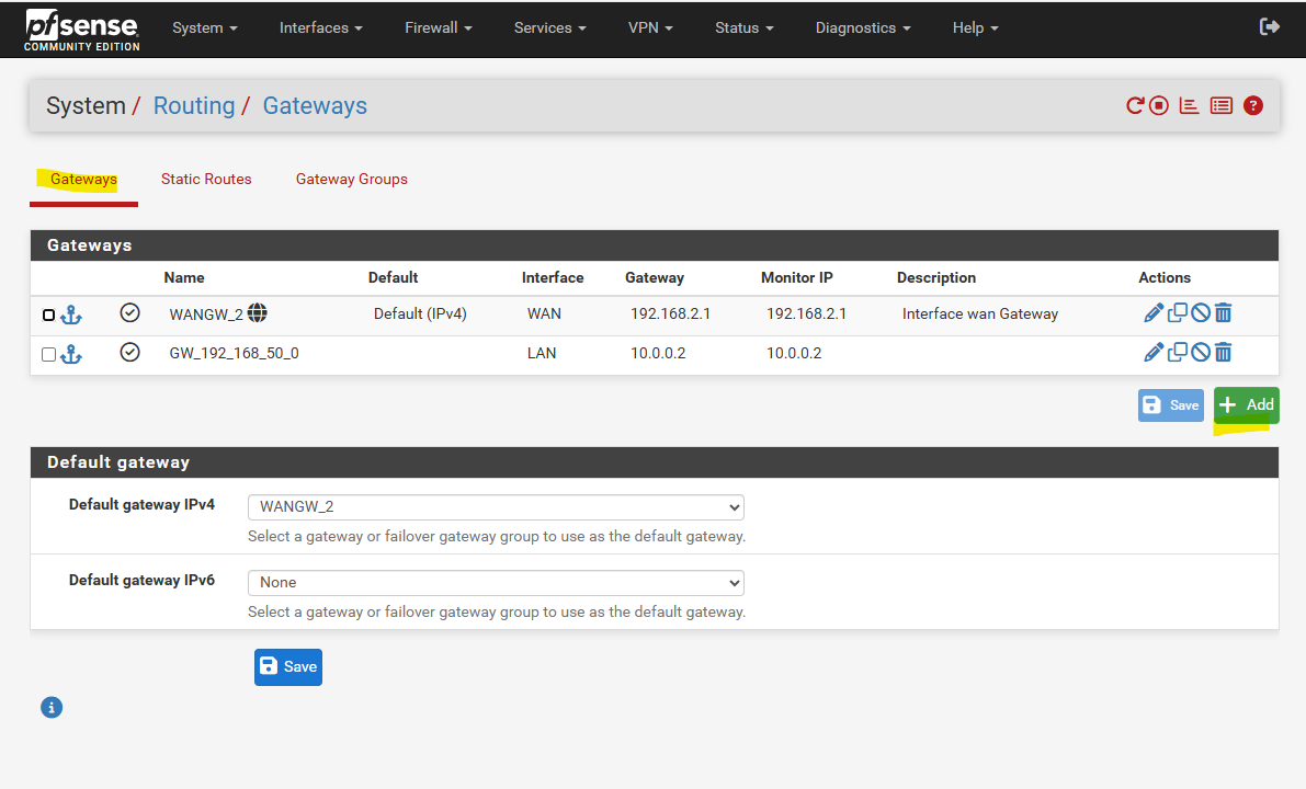
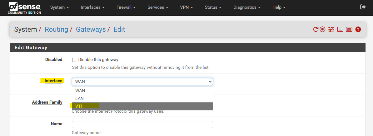
For the Interface select tunnel interface.
Enter a name and for the Gateway IP Address we need to enter the IP address of the virtual tunnel interface IP we assigned on phase 2 tunnel for the remote network (Azure), in my case 172.17.9.254.
Even Azure don’t care about as mentioned when BGP is disabled. We just need this for pfSense to be able to forward traffic to Azure through this virtual point-to-point link within the phase 1 SA (Security Association).
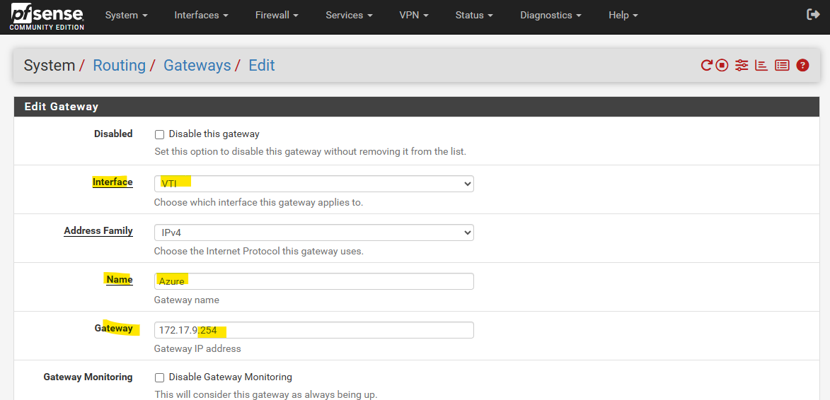
The rest I will leave on its default settings and click on Save.
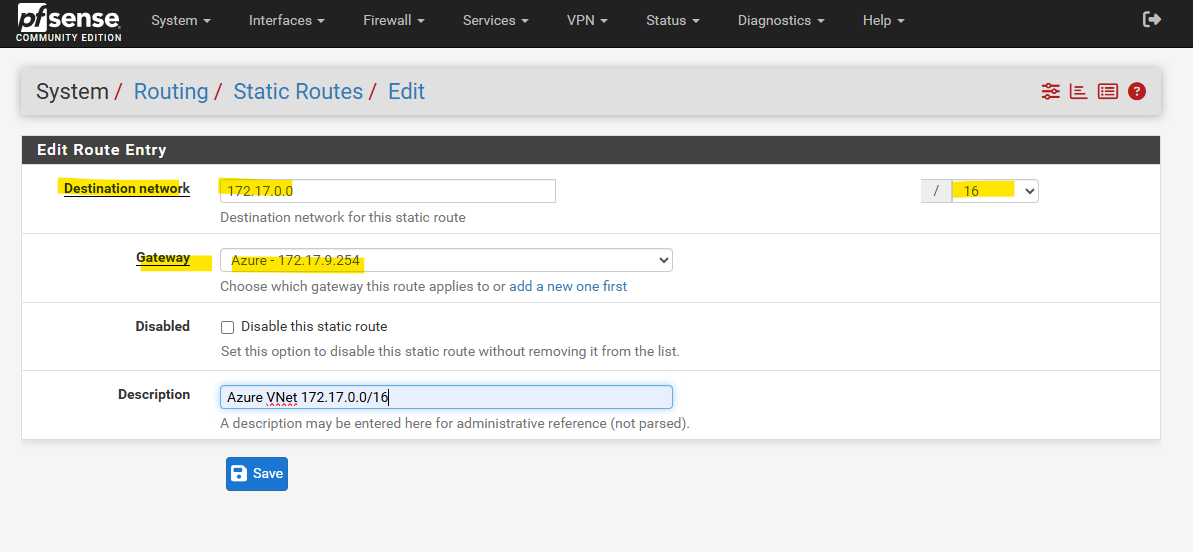
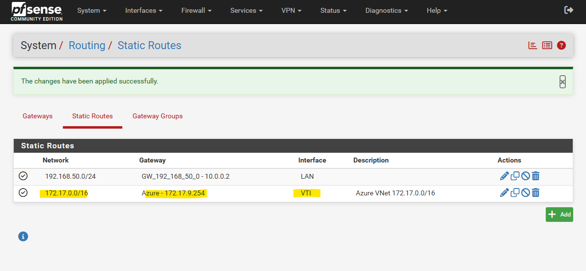
We can now add our new static route to the Azure virtual network 172.17.0.0/16 by using our newly created gateway (virtual tunnel interface and its IP address) for. Select the Static Routes tab and click on + Add.
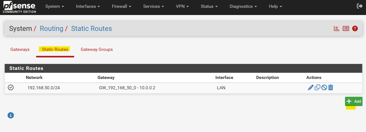
Enter your Azure’s virtual network address, select its subnet mask and for the gateway select the virtual tunnel interface gateway we created.
Finally click on Save.
So from now on traffic should be routed successful between both sides in case we already allow traffic between both on the firewall rules as shown below.
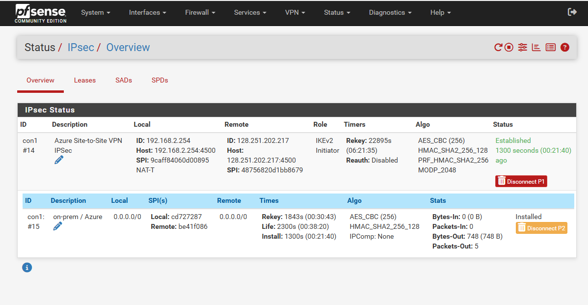
I will also check if the tunnel is up and running under Status -> IPsec, looks good.
Also in Azure.
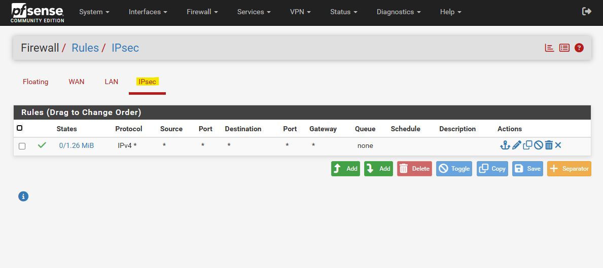
Allow Traffic between both Sides
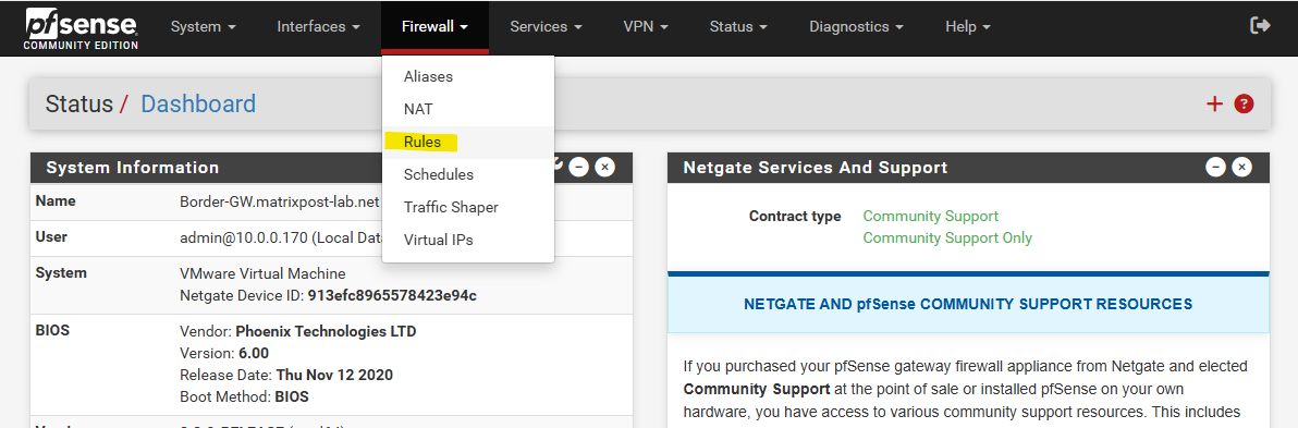
To allow traffic between our local on-prem network and Azure, we also need to allow this traffic on pfSense. Therefore navigate to Firewall -> Rules.
For my lab environment I will allow all IPv4 traffic. You may want to restrict these for production.
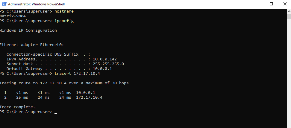
Check Traffic Flow between both Sides
Here initiated traffic from an internal on-prem host to a virtual machine running in my Azure’s virtual network with the IP address 172.17.10.4.
Looks good.
And vice versa, looks good.
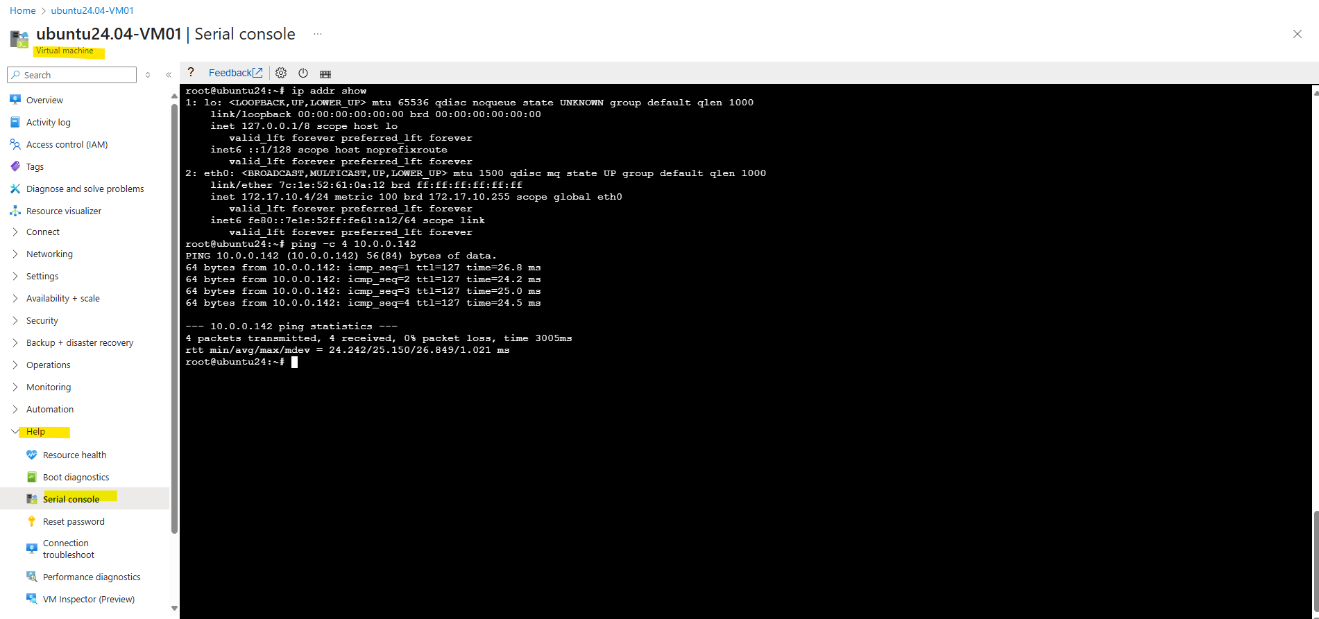
And finally from an internal host which runs in a second internal subnet 192.168.50.0/24 to check if really multiple subnets will be routed successfully through this one phase 2 tunnel aka transit network.
Looks also good.
10.0.0.1 is pfSense.

And vice versa. Looks also good.

Links
Create a site-to-site VPN connection in the Azure portal
https://learn.microsoft.com/en-us/azure/vpn-gateway/tutorial-site-to-site-portalAzure VPN Gateway vs. ExpressRoute – Quick comparison
https://techcommunity.microsoft.com/t5/fasttrack-for-azure/azure-vpn-gateway-vs-expressroute-quick-comparison/ba-p/3725670Introduction to strongSwan
https://docs.strongswan.org/docs/latest/howtos/introduction.htmlstrongSwan – Route-based VPN
https://docs.strongswan.org/docs/latest/features/routeBasedVpn.html?utm_source=chatgpt.compfSense – IPsec Tunnel Design
https://docs.netgate.com/pfsense/en/latest/vpn/ipsec/configure-design.htmlIPsec and firewall rules
https://docs.netgate.com/pfsense/en/latest/vpn/ipsec/firewall-rules.html