Set up an Azure Hub-Spoke Network Architecture by using Azure Firewall and S2S IPSec VPN Cross-premises Network Connection
A hub-spoke network architecture in Azure provides a scalable and secure way to centralize shared services (like Azure Firewall) in a hub virtual network (VNet) while connecting multiple spoke virtual networks for workloads like e.g. virtual machines.
By integrating Site-to-Site (S2S) IPSec VPN, you can extend this model to cross-premises networks, enabling secure hybrid connectivity between on-premises data centers and Azure.
In this post, we will see step by step how to set up a hub-spoke topology with Azure Firewall as the central security control point and IPSec VPN for cross-premises connectivity, ensuring secure and efficient traffic routing across your hybrid cloud environment.
Further we will see how we can configure the Azure Firewall in forced tunneling mode.
Forced tunneling lets you redirect or “force” all Internet-bound traffic back to your on-premises location via S2S VPN tunnel for inspection and auditing. This is a critical security requirement for most enterprise IT policies. Unauthorized Internet access can potentially lead to information disclosure or other types of security breaches.
- Introduction
- Creating the Virtual Networks for Hub and Spoke
- Peering the Hub and Spoke Virtual Network
- Creating a new Linux VM (Workload) in the Spoke Virtual Network
- Creating a Route Table for the Spoke Virtual Network and Route to the Internet with Next Hop Azure Firewall
- Configure Azure Firewall Rules to allow Traffic
- Determine Effective Routes for a Virtual Network Gateway where BGP is enabled
- Determine Effective Routes for a Virtual Machine (VMs NIC)
- Firewall Management NIC and Forced Tunneling
- ICMP Networking filtering rules will not work in Azure Firewall.
- Links
Introduction
Hub-spoke is one of the network topologies recommended by the Cloud Adoption Framework. See, Define an Azure network topology to understand why this topology is considered a best practice for many organizations.
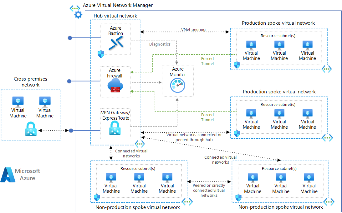
Download a Visio file of this architecture.
Hub virtual network
The hub virtual network hosts shared Azure services.
Workloads hosted in the spoke virtual networks can use these services. The hub virtual network is the central point of connectivity for cross-premises networks. The hub contains your primary point of egress and provides a mechanism to connect one spoke to another in situations where cross virtual network traffic is needed.
A hub is a regional resource. Organizations that have their workloads in multiple regions, should have multiple hubs, one per region.
Spoke virtual networks
Spoke virtual networks isolate and manage workloads separately in each spoke. Each workload can include multiple tiers, with multiple subnets connected through Azure load balancers.
Spokes can exist in different subscriptions and represent different environments, such as production and non-production. One workload could even spread across multiple spokes.
In most scenarios, a spoke should only be peered to a single hub network and that hub network should be in the same region as the spoke.
These spoke networks follow the rules for default outbound access. A core purpose of this the hub-spoke network topology is to generally direct outbound Internet traffic through the control mechanisms offered by the hub.
Hub-spoke solutions are often responsible for providing a DNS solution to be used by all peered spokes, especially for cross-premises routing and for private endpoint DNS records.
Azure landing zones
The Azure landing zone architecture is based on the hub-spoke topology. In that architecture, the hub’s shared resources and network is managed by a centralized platform team, while spokes share a co-ownership model with the platform team and the workload team that is using the spoke network.
All hubs reside in a “Connectivity” subscription for centralized management, while spoke virtual networks exist across many individual workload subscriptions, called application landing zone subscriptions.
Source: https://learn.microsoft.com/en-us/azure/architecture/networking/architecture/hub-spoke
What is the Microsoft Cloud Adoption Framework for Azure?
The Microsoft Cloud Adoption Framework for Azure is a full lifecycle framework that enables cloud architects, IT professionals, and business decision makers to achieve their cloud adoption goals. It provides best practices, documentation, and tools that help you create and implement business and technology strategies for the cloud.
The Cloud Adoption Framework brings together cloud adoption best practices from Microsoft employees, partners, and customers. The framework provides tools, guidance, and narratives. The tools it includes help you shape your technology, business, and people strategies to achieve the best business outcomes possible through your cloud adoption effort. Use the following table to review the guidance for each methodology.
Source: https://learn.microsoft.com/en-us/azure/cloud-adoption-framework/overview
Creating the Virtual Networks for Hub and Spoke
For this post I will first create two resource groups which will later host the resources of the hub and the spoke network.
- rsg-matrix-weu-hub
- rsg-matrix-weu-spoke
For the Hub Network
I will first create the hub virtual network which will also contain the cross-premise gateway, in my case a site-to-site IPSec route based VPN.
Further the hub virtual network will also contain the Azure Firewall to provide our primary point of egress traffic (WAN traffic).
All outbound traffic to the internet from workloads running in the hub- and spoke virtual network will finally be routed through this Azure Firewall.
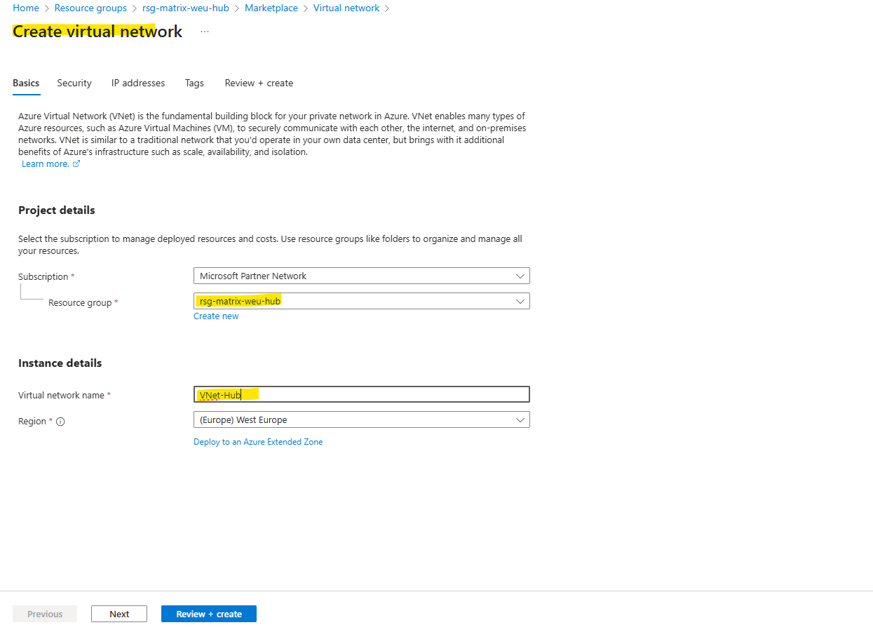
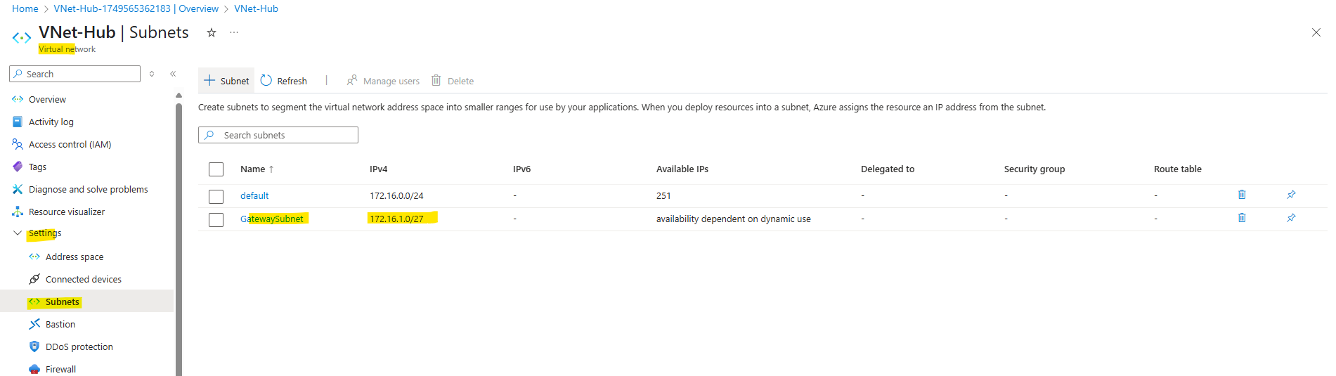
For the hub network I will use the address space 172.16.0.0/16.
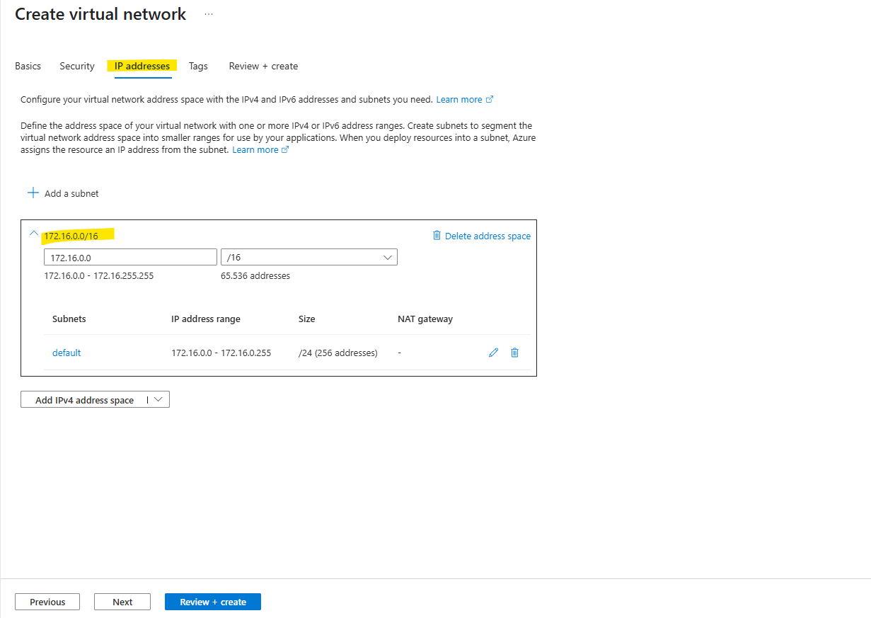
I will also already create a gateway subnet in which later the virtual network gateway will be created.
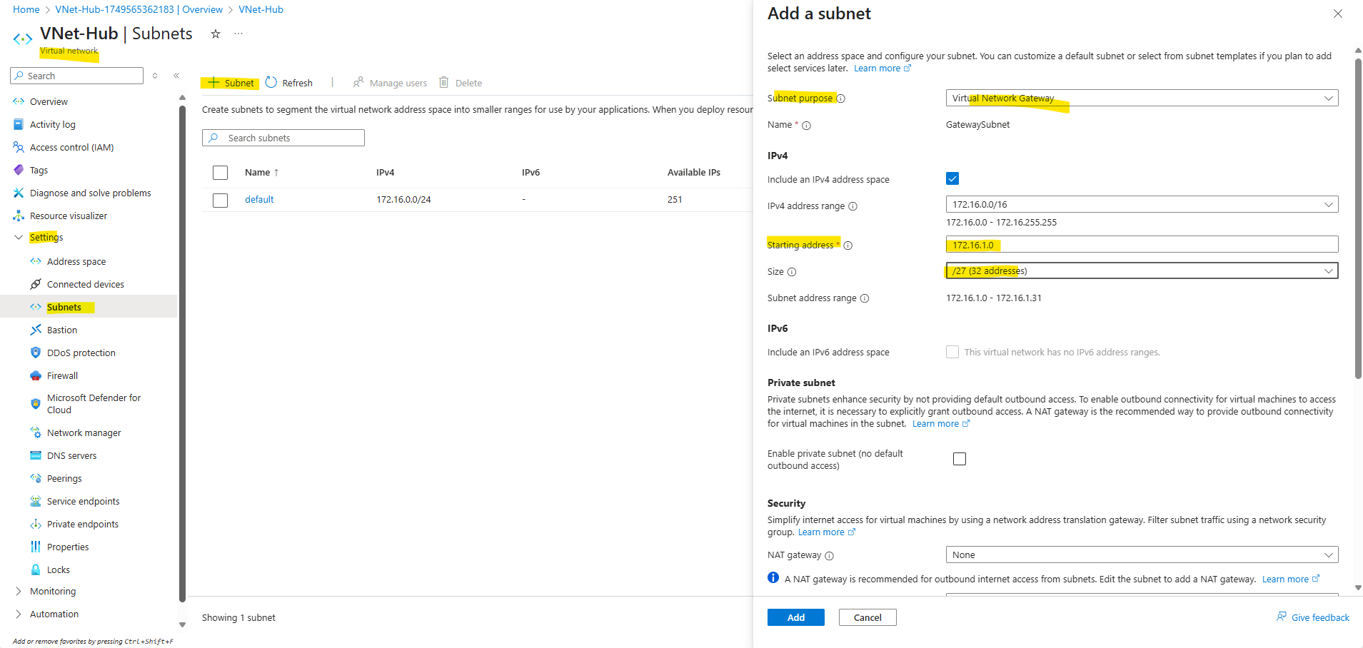
Creating the cross-premise gateway
Next I will create the S2S IPSec VPN tunnel with my on-premise network, in Azure we need to create here the virtual network gateway and local network gateway (containing the configuration for the on-premise VPN device).
I will skip this step here, you can see this step by step in my following two posts. As mentioned, the cross-premise gateway (in my case the virtual network gateway for the S2S IPSec VPN tunnel) will be deployed in the hub virtual network.
I will create here a route based VPN with BGP enabled.
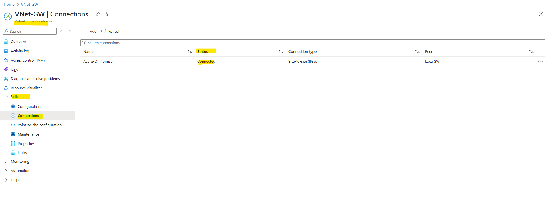
Finally the IPSec route-based VPN tunnel is up and running, also advertising routes between Azure and on-premise by using BGP is working.
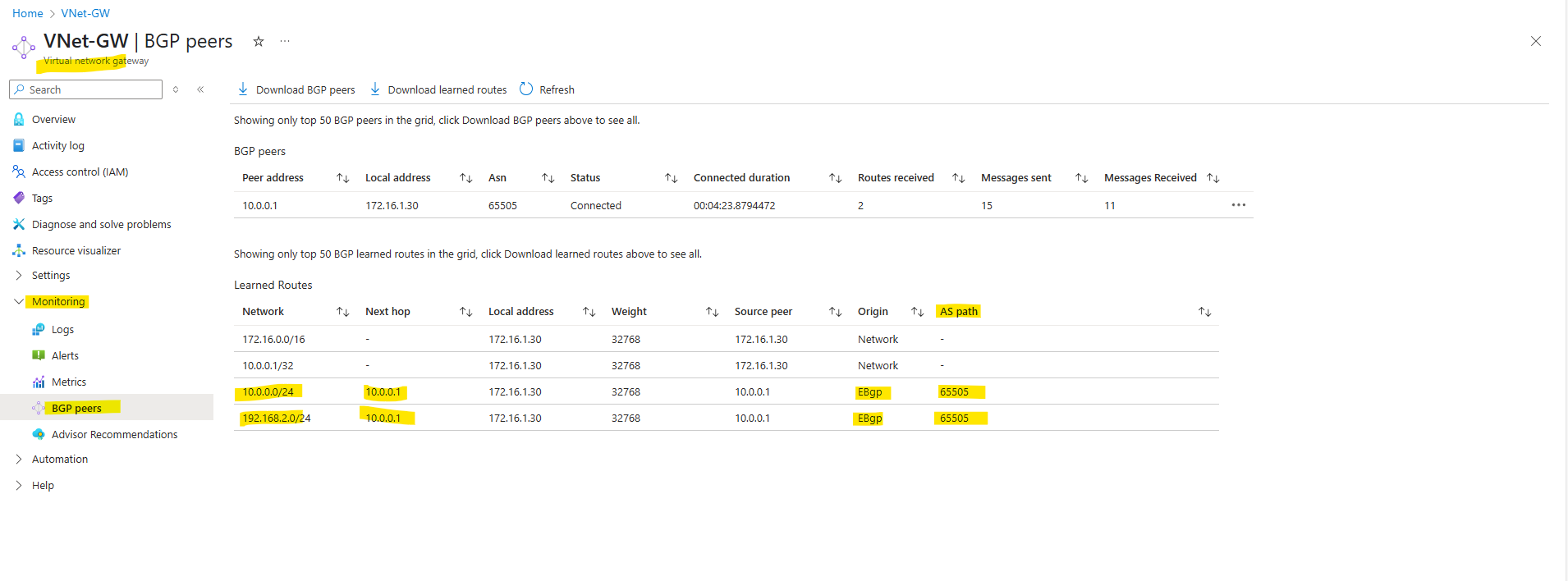
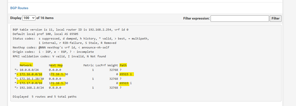
Here you can see both of my on-premise subnets which will be advertised to Azure by using BGP.
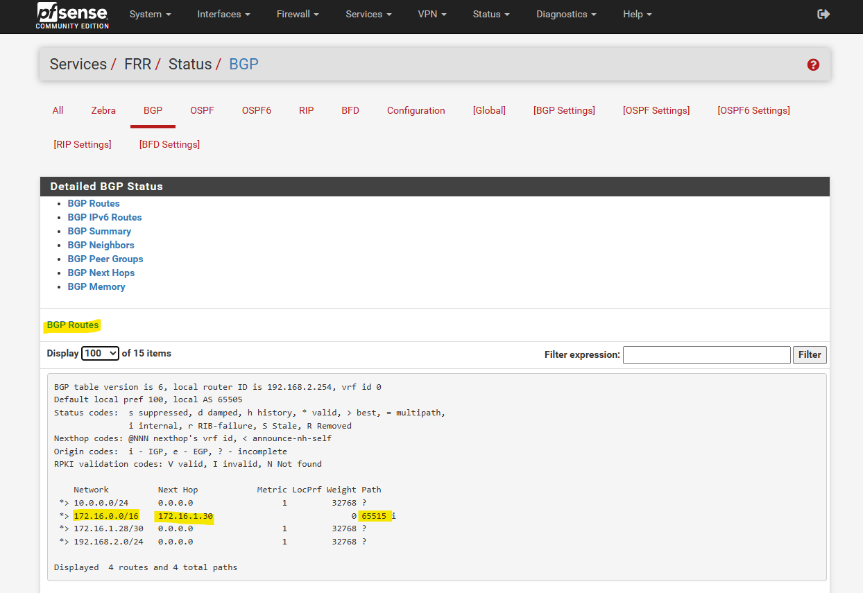
And here you can see the advertised hub network by Azure to my on-premise VPN device (pfSense). Later and shown further down after creating the spoke virtual network and peering it with the hub virtual network, we should see here also the advertised spoke virtual network (172.17.0.0/16).
Under Path you can see the AS number from the Azure BGP peer which is 65515 (Private ASN reserved by Azure).
Creating the Azure Firewall
About how to create the Azure Firewall, you can read my following post or directly here.
I will finally deploy it in the hub virtual network and a dedicated subnet shown in this post.
In the post above I was creating the Azure Firewall Subnet during the deployment of the hub virtual network, now because I already created the hub virtual network, I have to create this subnet separately.
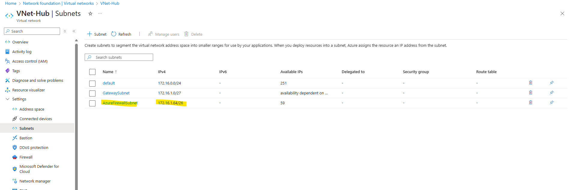
Azure Firewall requires a dedicated subnet, named AzureFirewallSubnet, within the virtual network where it will be deployed. This subnet is specifically for the firewall and is not shared with other resources.
The size of the AzureFirewallSubnet subnet is /26.
Azure Firewall must provision more virtual machine instances as it scales. A /26 address space ensures that the firewall has enough IP addresses available to accommodate the scaling.For more information about the subnet size, see Azure Firewall FAQ.
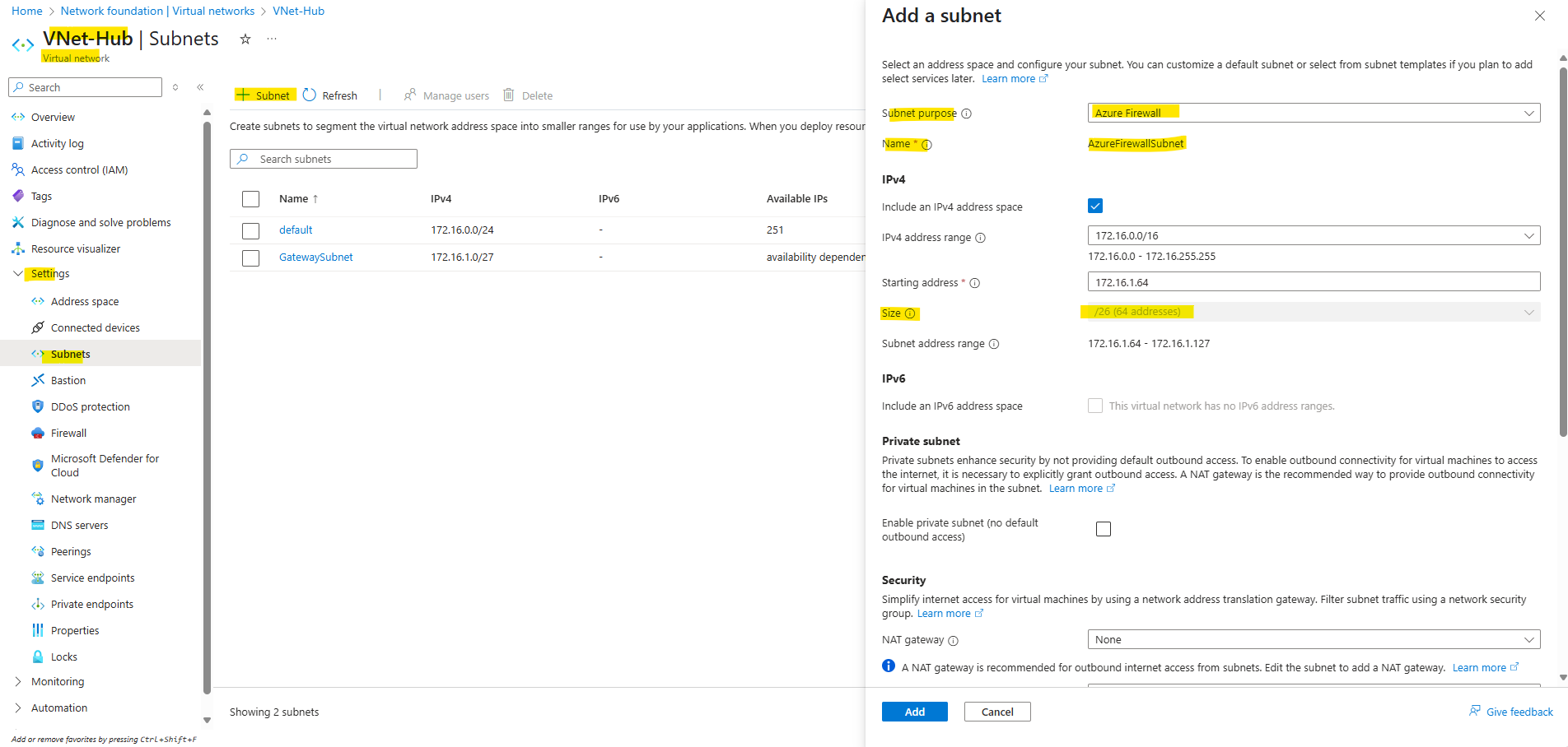
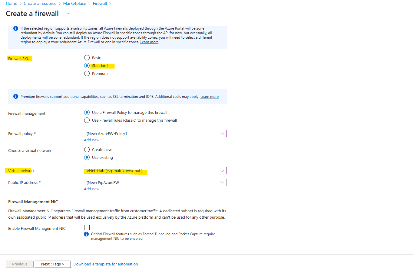
Also keep in mind when creating the Azure Firewall by using the Basic SKU which is the cheapest version, by default a Management NIC will be deployed and requires the virtual network in which the firewall will be deployed, contains a subnet named AzureFirewallManagementSubnet.
For Standard and Premium SKU we can disable the Firewall Management NIC and forced tunneling.
More about the Firewall Management NIC and forced tunneling here.
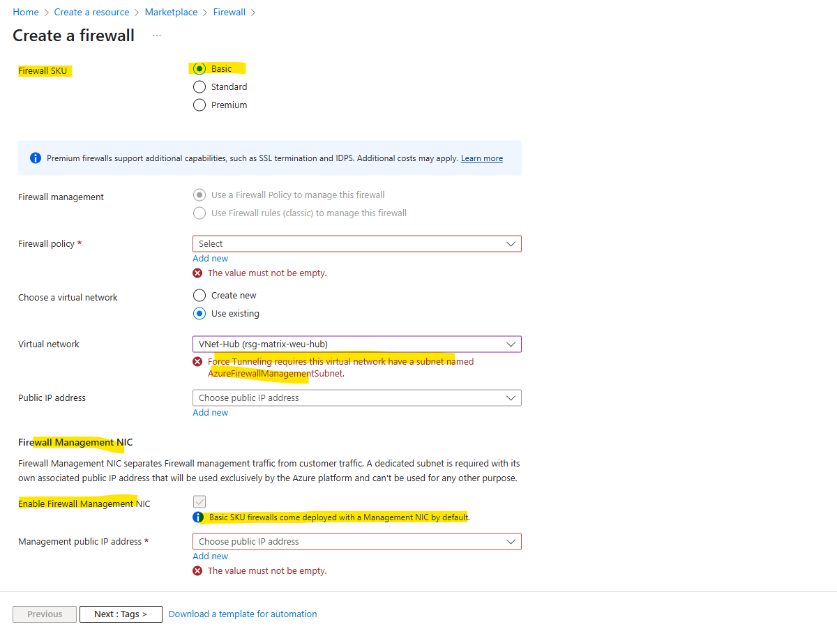
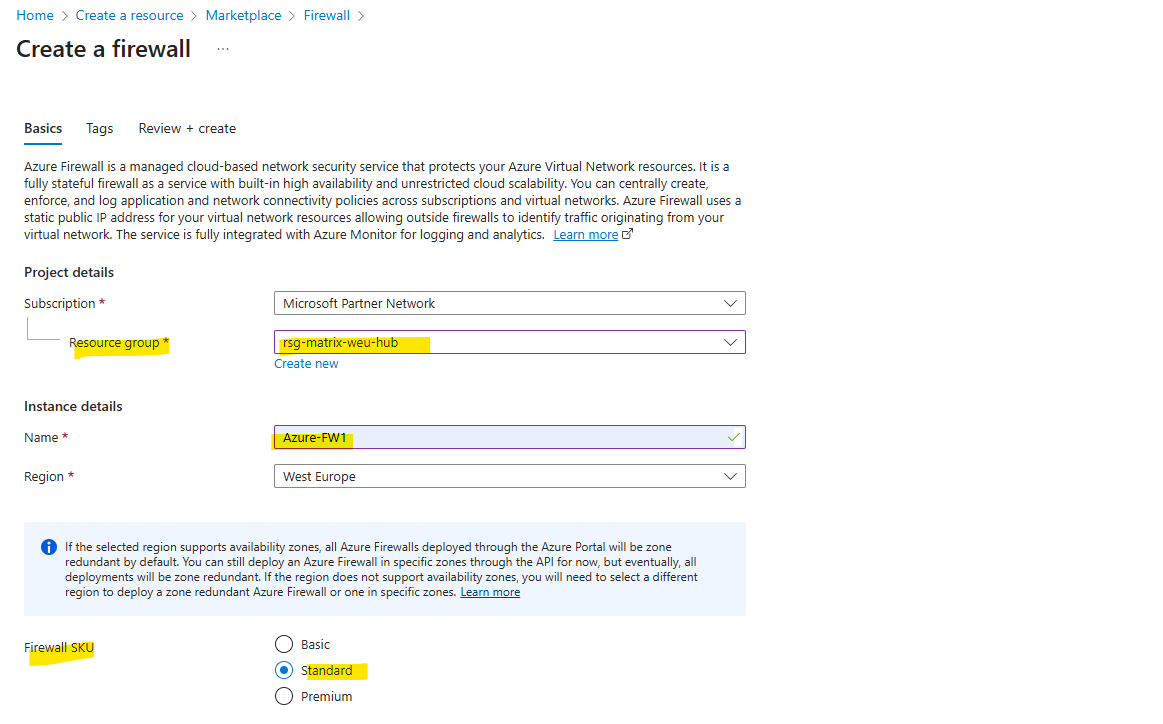
So I will use here first the Standard SKU without the Firewall Management NIC and forced tunneling and later further down also shown this by using the Basic SKU.
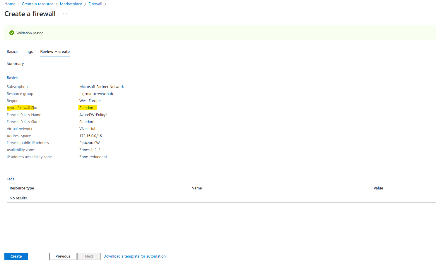
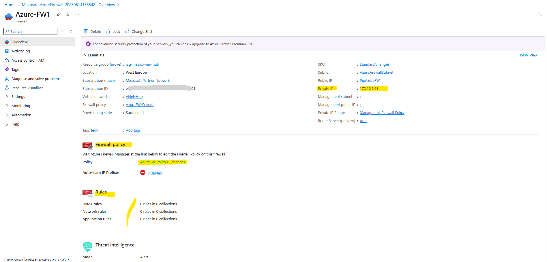
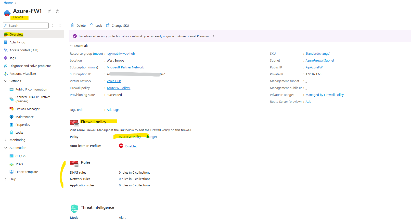
Finally the Azure Firewall was deployed in my hub virtual network.
So far no rules are configured to allow outbound (Network rules below) or inbound (DNAT rules below, published services) traffic. We will configure the Azure Firewall later further down.
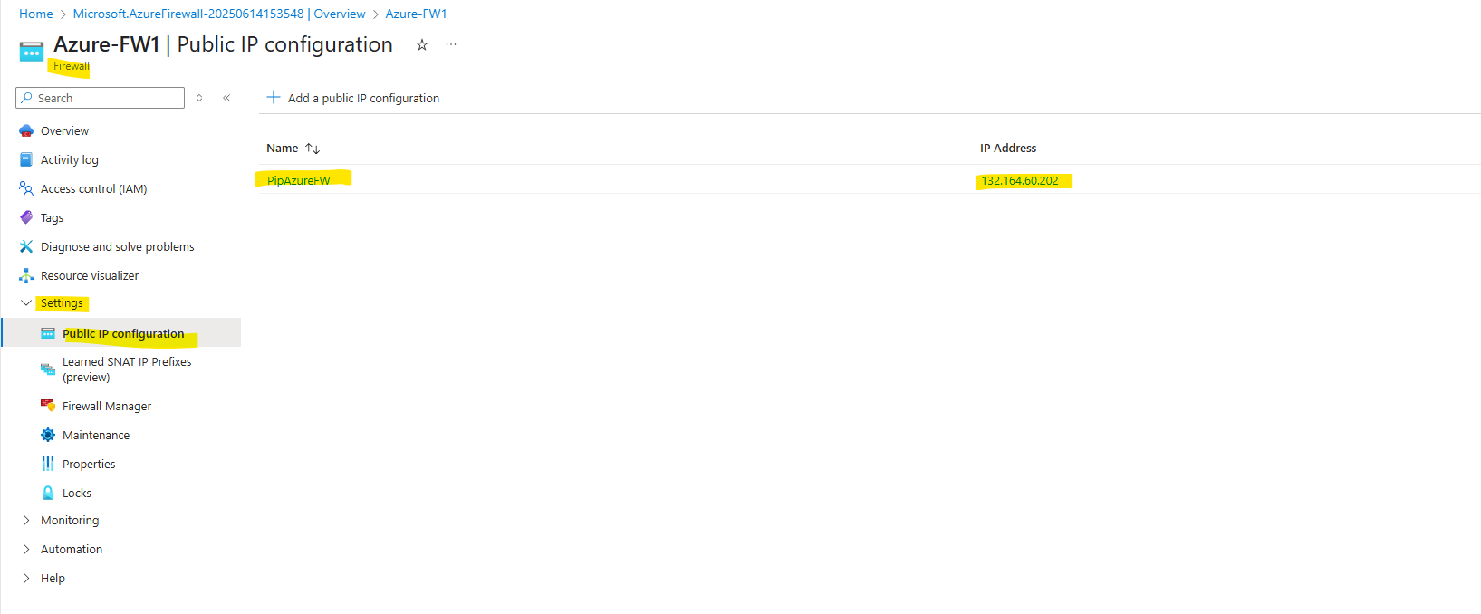
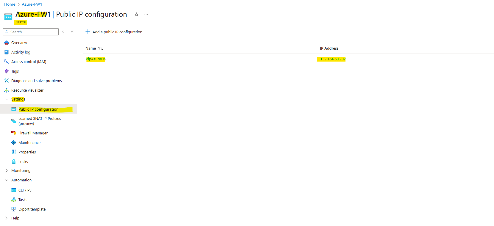
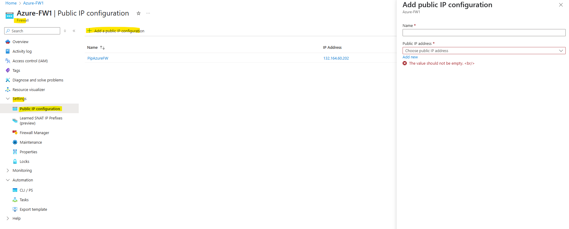
The static public IP address of our Azure Firewall we will see under Settings -> Public IP configuration.
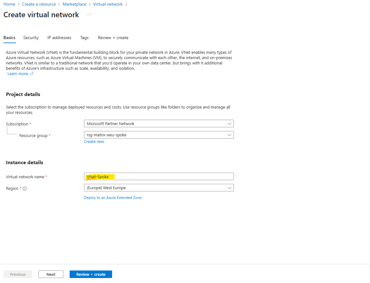
For the Spoke Network
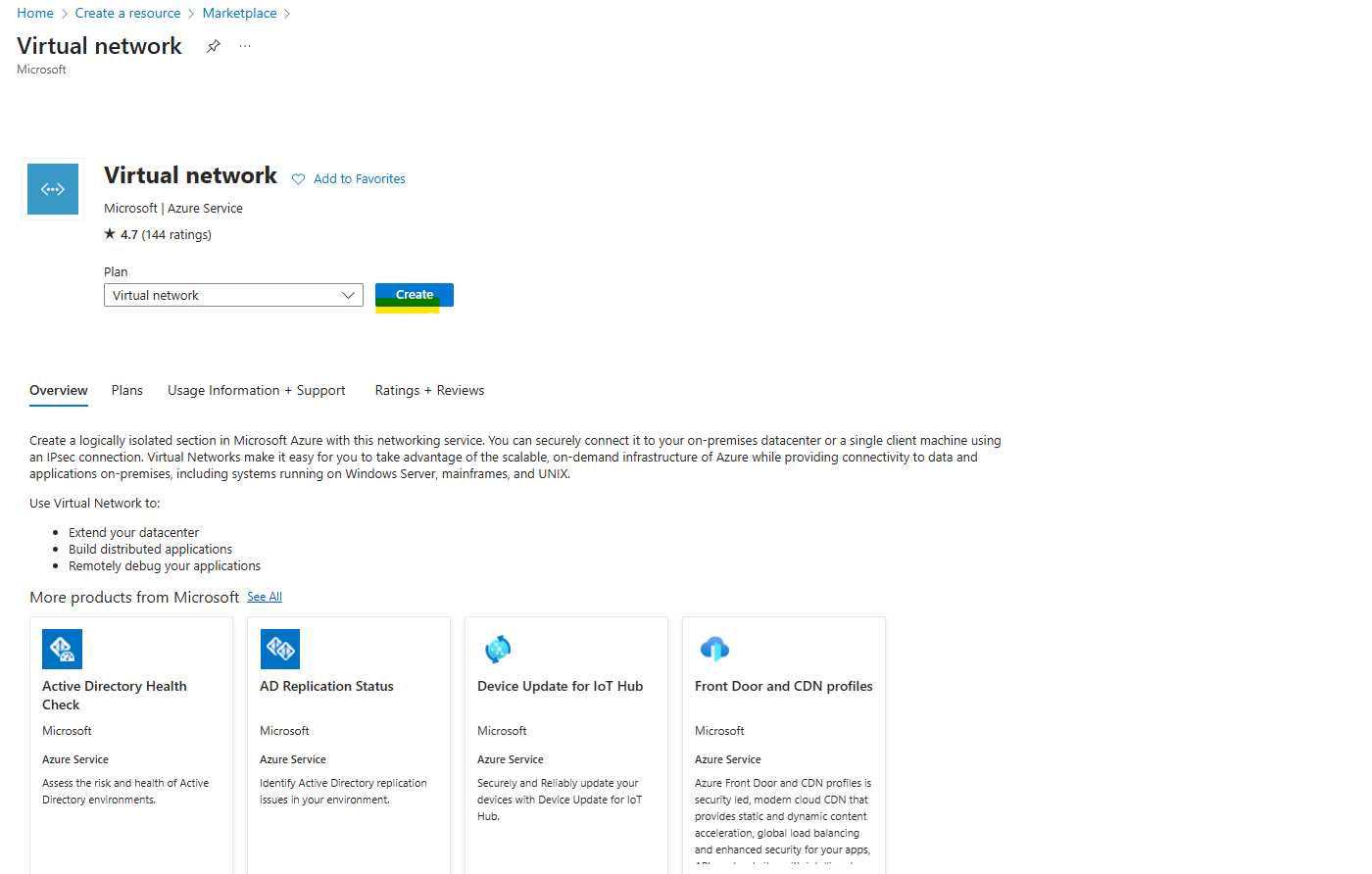
We will now create the spoke virtual network which will contain the workloads and then peering it with the hub virtual network to provide cross premise connectivity to my on-premise network (VPN Gateway) and outbound internet traffic through the Azure Firewall both running in the hub virtual network.
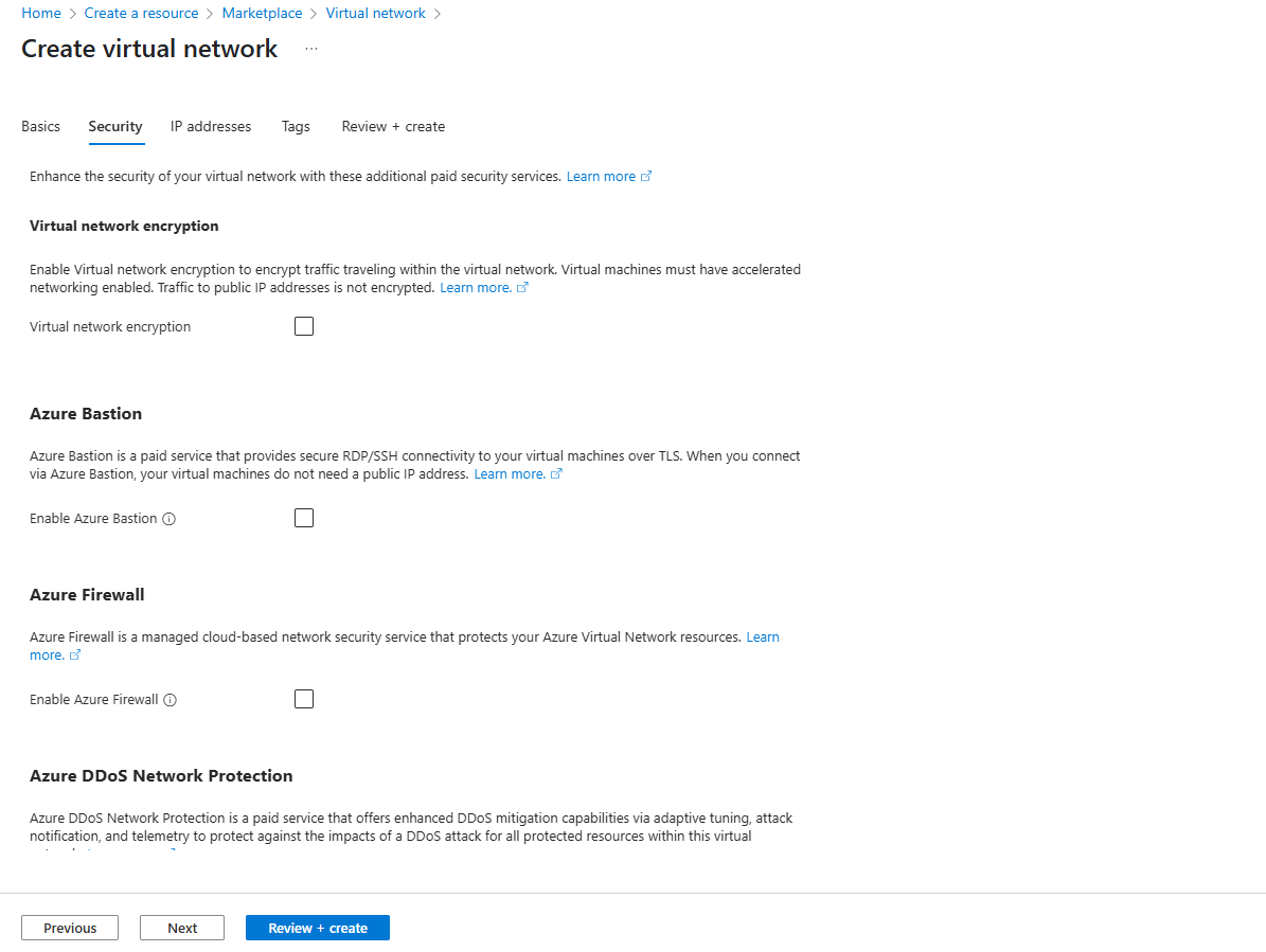
The settings on the Security tab I will leave blank.
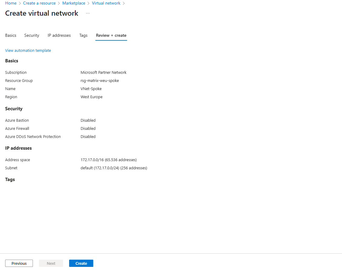
For the network address space I will use for the spoke virtual network here 172.17.0.0/16, finally we need an address space which doesn’t overlap with our other existing networks in Azure and on-premise.
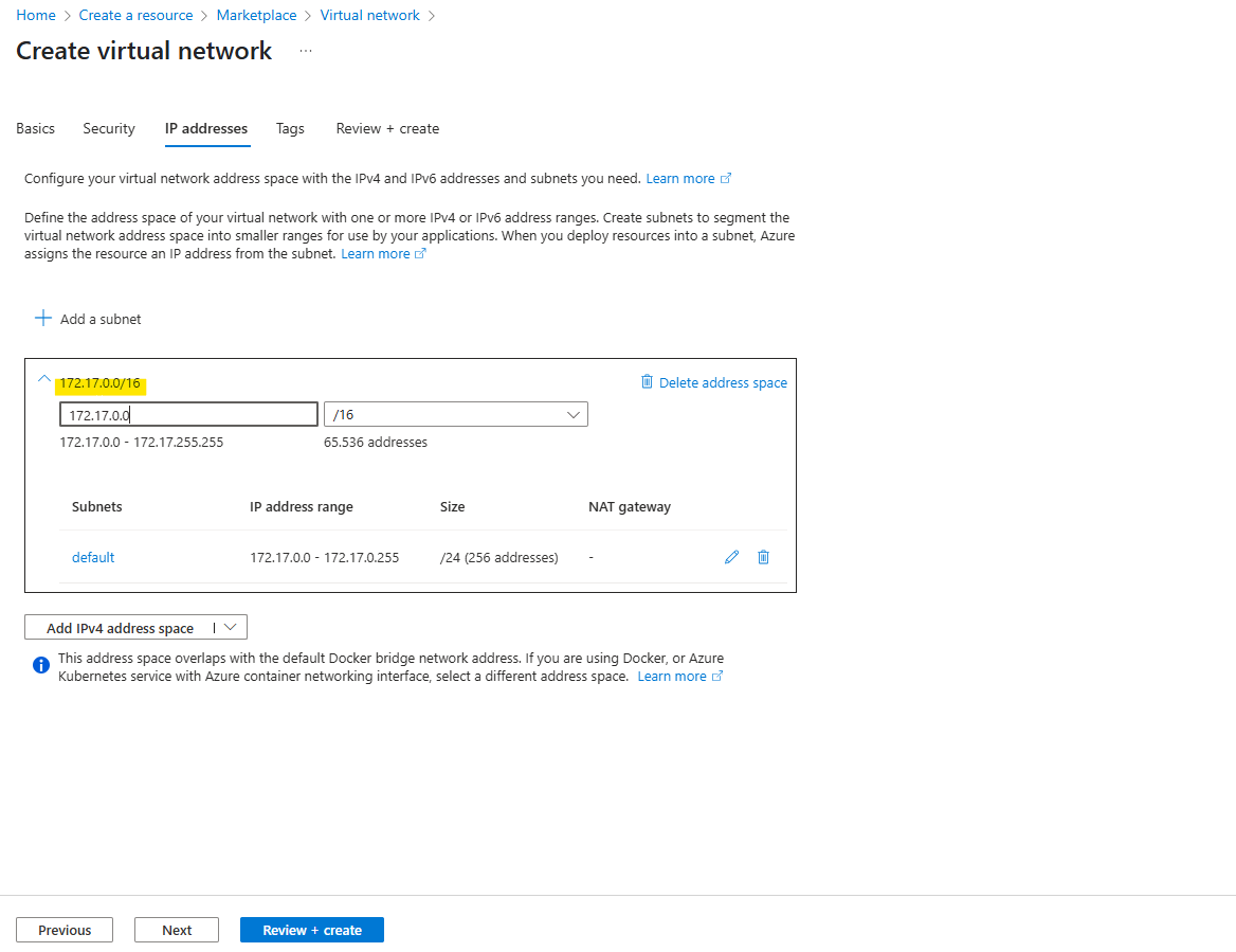
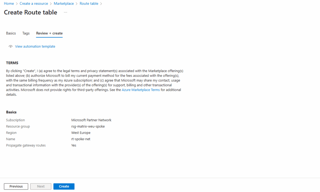
Finally click on Create.
Next we will peer this workload virtual network (Spoke network), in which we will create a new Linux VM that finally is our workload, with the hub virtual network where the Azure Firewall is running and therefore providing outbound internet access to these workloads running in both virtual networks, the hub- and spoke virtual network which are peered.
The VM then should be using the static public IP of the Azure Firewall for outbound internet access. We will check this later.
In contrast when using the default outbound access here, customers don’t own the default outbound access IP. This IP may change, and any dependency on it could cause issues in the future.
Peering the Hub and Spoke Virtual Network
To peer both virtual networks, we can do the configuration on one of them. I will configure the peering on the spoke virtual network, but as mentioned could be also done on the hub virtual network, finally doesn’t matter.
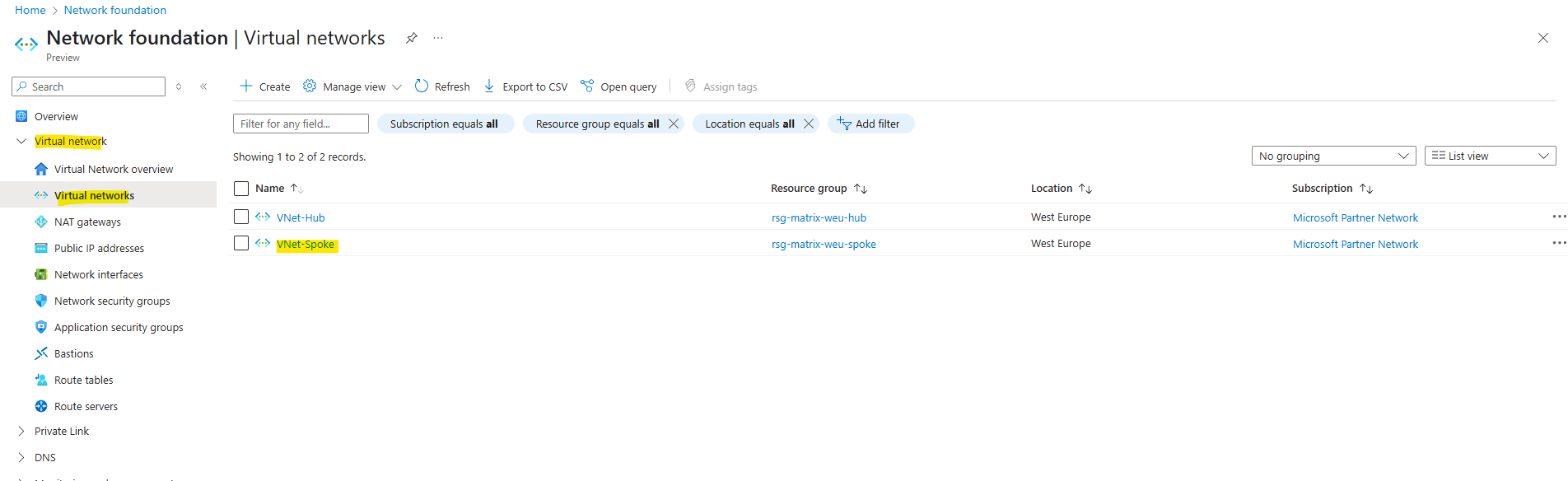
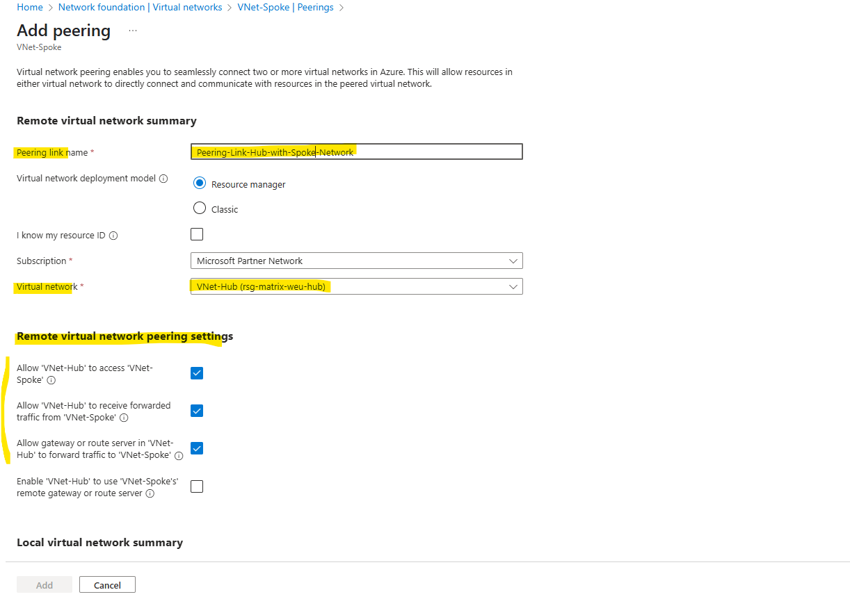
On the selected virtual network, under Settings -> Peerings click on Add.
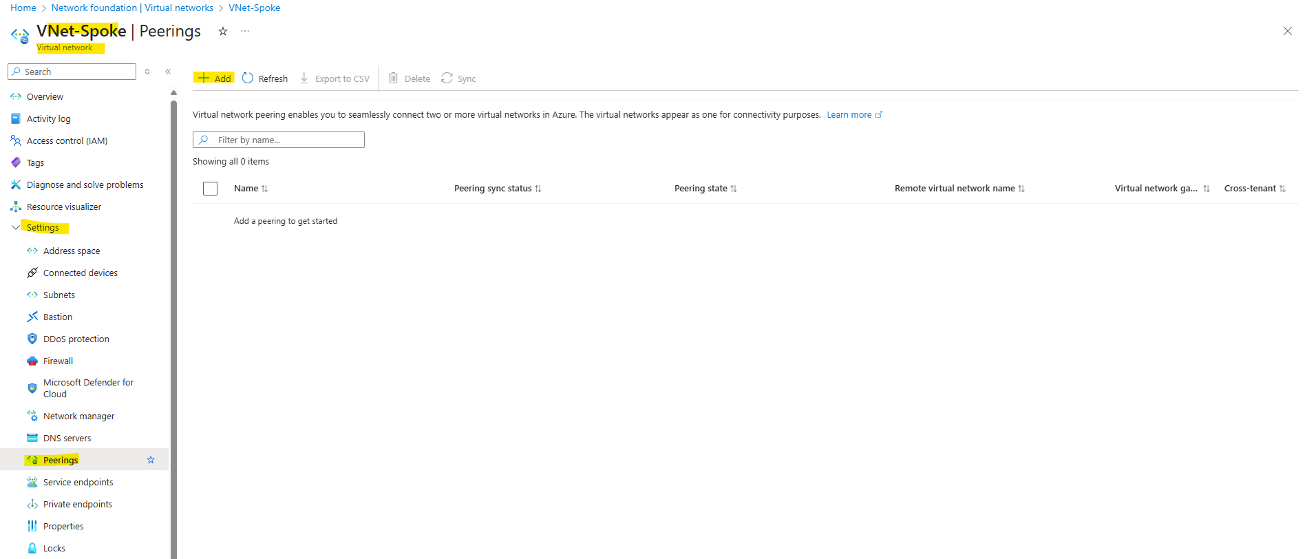
Below select the other virtual network that you want to peer your virtual network on which you will add this peering link.
So in my case I will create the peering link on the spoke virtual network and therefore need to select below the hub virtual network to peer with.
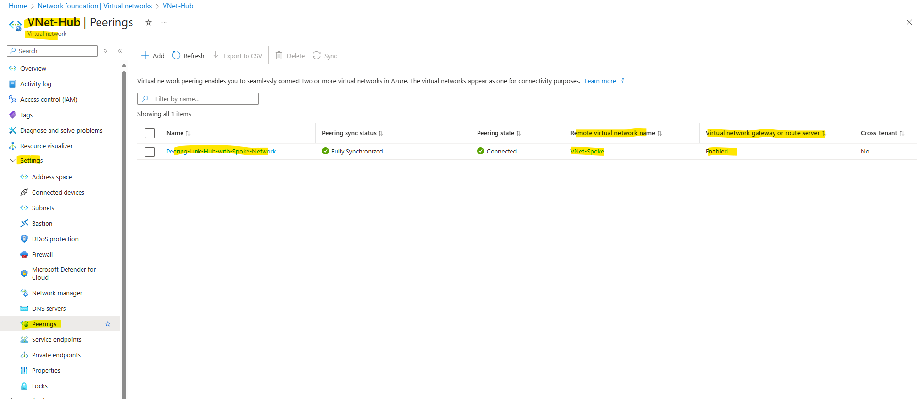
This is the peering link which is created for the remote virtual network (hub virtual network)
Further I will select the following highlighted three checkboxes to finally allow traffic be routed between both virtual networks.
By checking the third checkbox below with Allow gateway or route server in ‘VNet-Hub’ to forward traffic to ‘VNet-Spoke’, finally we will allow/enable the VNet-HUB to forward traffic from VNet-Hub’s VPN Gateway (traffic to and from on-premise) and the Azure Firewall to the peered spoke virtual network.
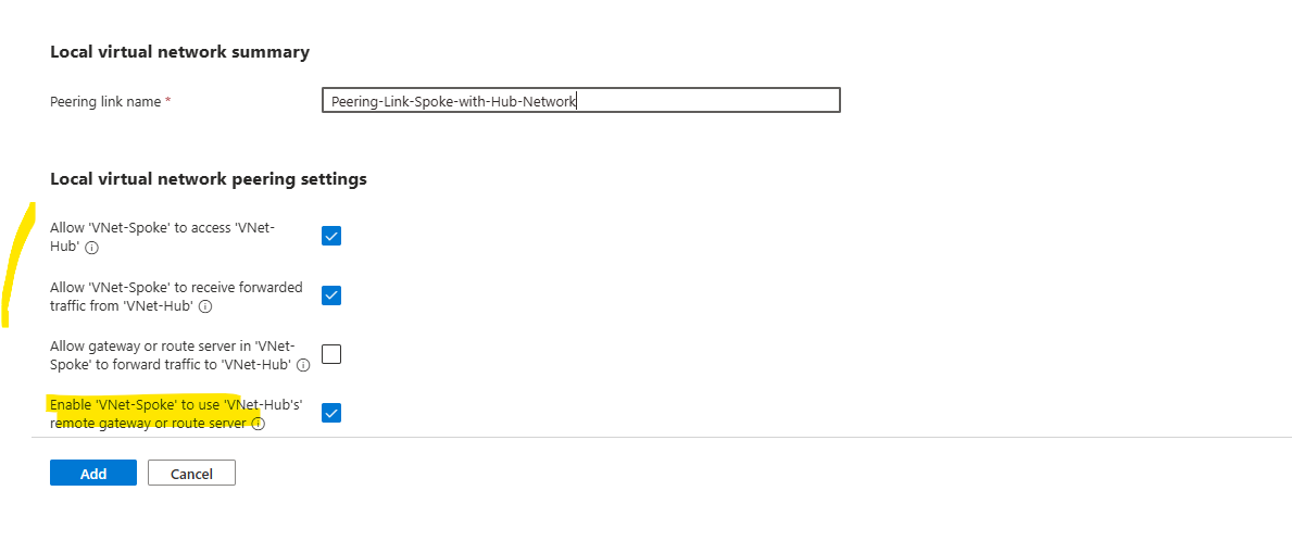
For the local virtual network peering link we enable the following three option to allow traffic be routed between both virtual networks.
This is the peering link which is created for the local virtual network (spoke virtual network) we do the configuration.
By checking the third checkbox below with Enable ‘VNet-Spoke’ to use ‘VNet-Hub’s’ remote gateway or route server, finally we will allow/enable the VNet-Spoke to use the VNet-Hub’s VPN Gateway (traffic to an from on-premise) and the Azure Firewall.
This will also allow that BGP routes for the hub virtual network will be advertised to our on-premise network.
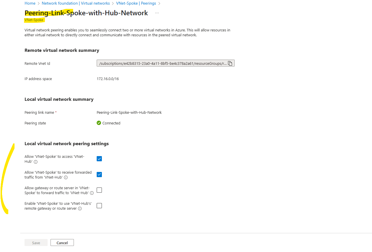
Peering created on the spoke virtual network.
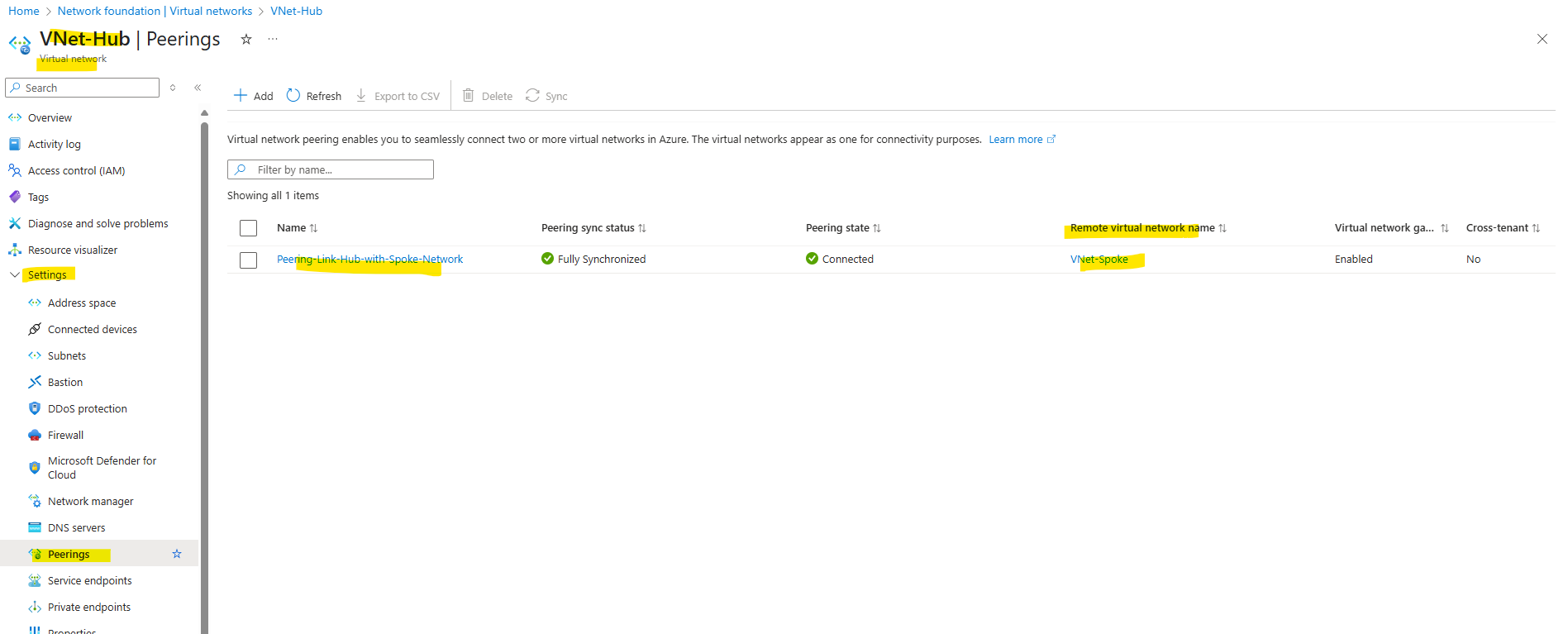
By clicking on the peering link above, we can adjust the settings anytime.
And as mentioned we also created a peering link in the hub virtual network.
On my on-premise VPN device (pfSense) I can already see that now both address spaces from the hub- and spoke virtual network will be advertised via BGP as mentioned previously.
Creating a new Linux VM (Workload) in the Spoke Virtual Network
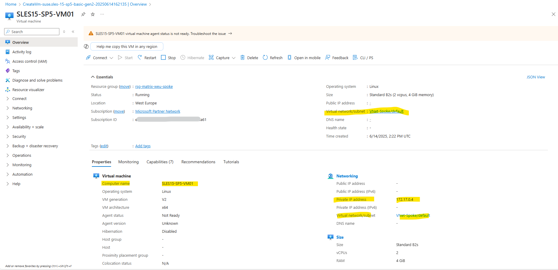
To demonstrate how workloads in the spoke virtual network will use the Azure Firewall running in the hub virtual network for outbound internet access, I will create here a Linux VM which will be the workload in the spoke virtual network.
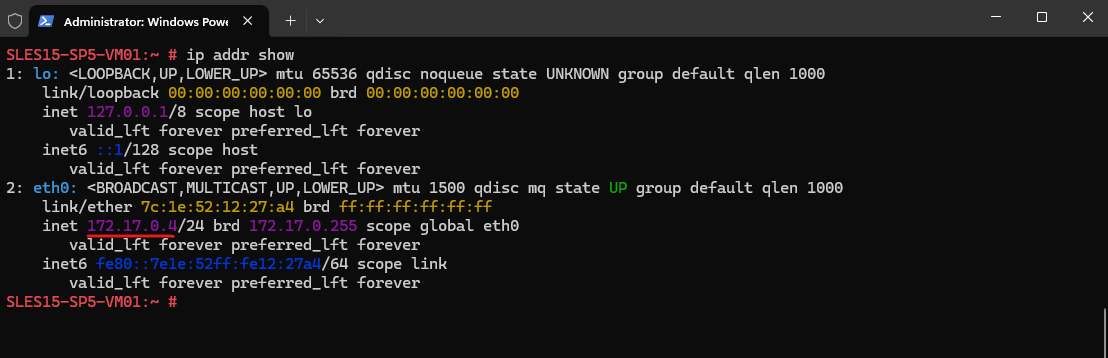
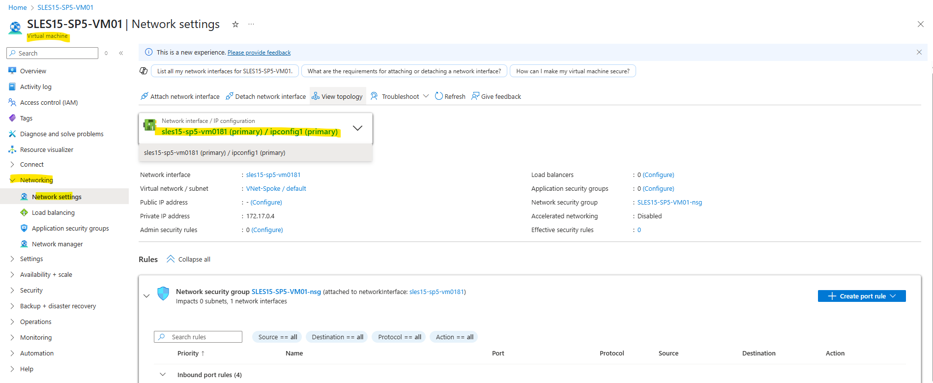
The virtual machine is just having a private IP address (172.17.0.4) assigned by the spoke virtual network and its default subnet 172.17.0.0/24.
So far the virtual machine running in the spoke virtual network which is peered with the hub virtual network is not using the Azure Firewall for outbound internet access.
It is still using the so called default outbound access for VMs in Azure.
In Azure, virtual machines created in a virtual network without explicit outbound connectivity defined, a default outbound public IP address is assigned. This IP address enables outbound connectivity from the resources to the Internet. This access is referred to as default outbound access.
This IP is implicit and belongs to Microsoft. This IP address is subject to change and it’s not recommended to depend on it for production workloads.
Also the default outbound access for VMs in Azure will be retired on 30 September 2025. More about you will find in my following post https://blog.matrixpost.net/default-outbound-access-for-vms-in-azure-will-be-retired-on-30-september-2025/.
By running the following command on the Linux VM located in the spoke virtual network, we can check which public IP address finally will be used. Google provides a special hostname here that returns your public IP in a TXT record.
# dig TXT +short o-o.myaddr.l.google.com @ns1.google.com
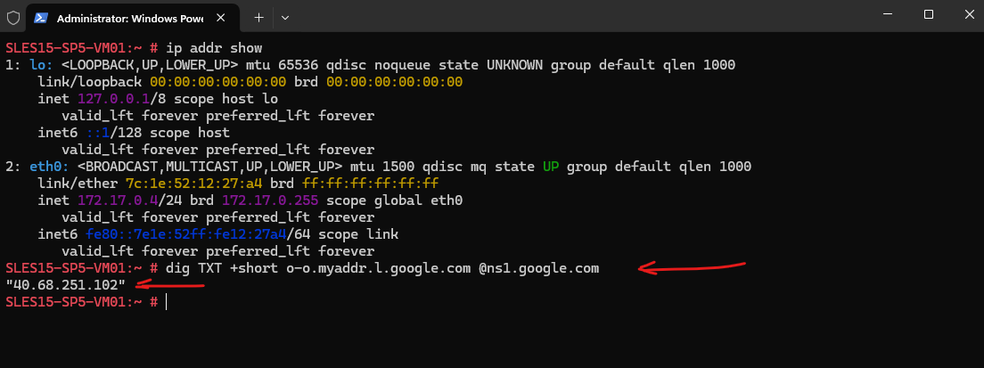
The virtual machine so far is using for outbound internet access the public IP address 40.68.251.102.
This IP is implicit and belongs to Microsoft and is provided by the default outbound access for VMs in Azure.
Below we can see on the network interface of the virtual machine under Help -> Effective routes that the route with the next hop for the Internet is called Internet, this finally is the default outbound access for VMs in Azure.
In order to route traffic to the Internet through our Azure Firewall running in the hub virtual network, we first need create a route table with a route for the Internet and next hop with the internal IP of the Azure Firewall.
Then we need to assign this route table to the spoke virtual network and its subnet where the workloads are running (so far the default subnet in my case).
Finally all workloads running in this subnet will then have this new route to the Internet (0.0.0.0/0).
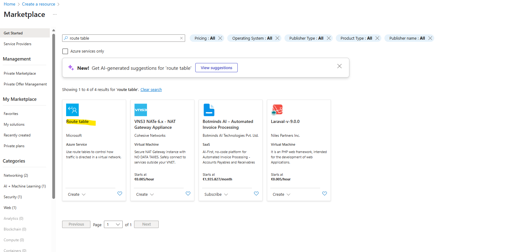
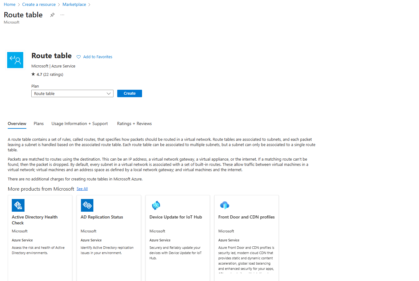
Creating a Route Table for the Spoke Virtual Network and Route to the Internet with Next Hop Azure Firewall
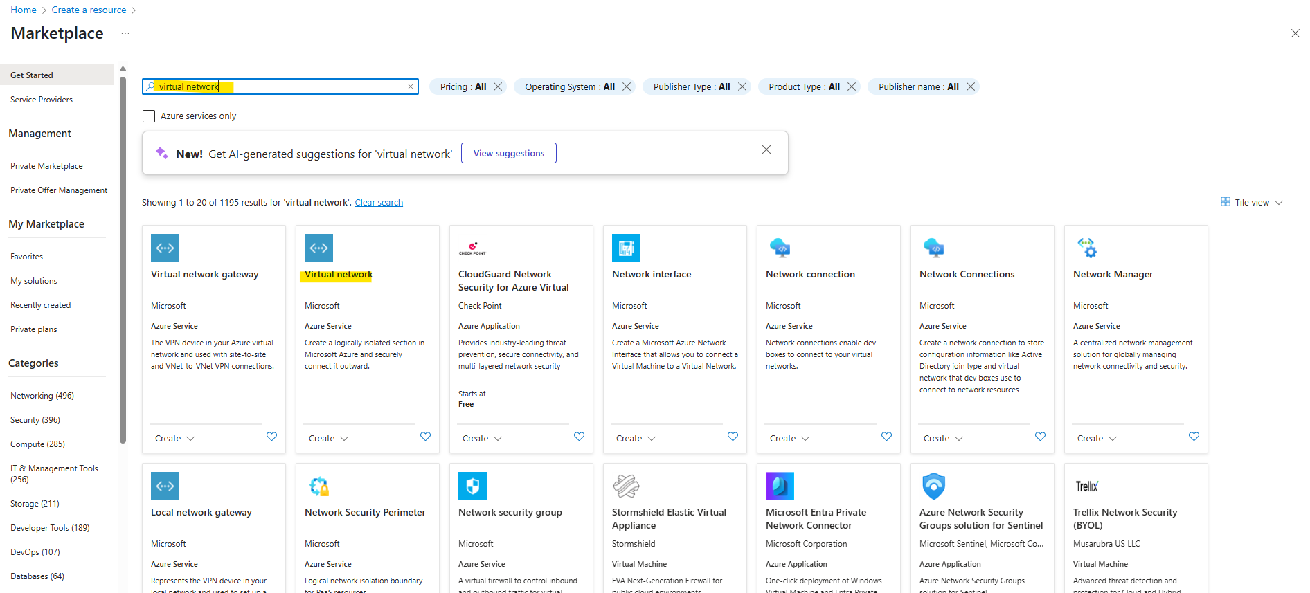
To create a new route table, search in the marketplace for route table and select it like shown below.
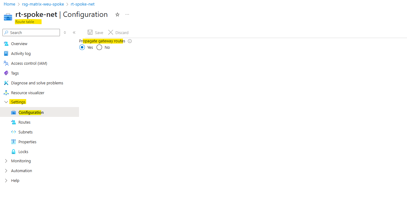
Because we want the workloads also have the route for the on-premise networks, we will leave the propagate gateway route on yes (default).
Select no, to prevent the propagation of on-premises routes to the network interfaces in associated subnets.
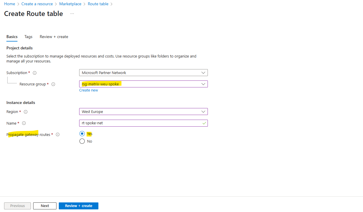

The gateway route propagation we can change anytime later on the route table under the configuration menu.
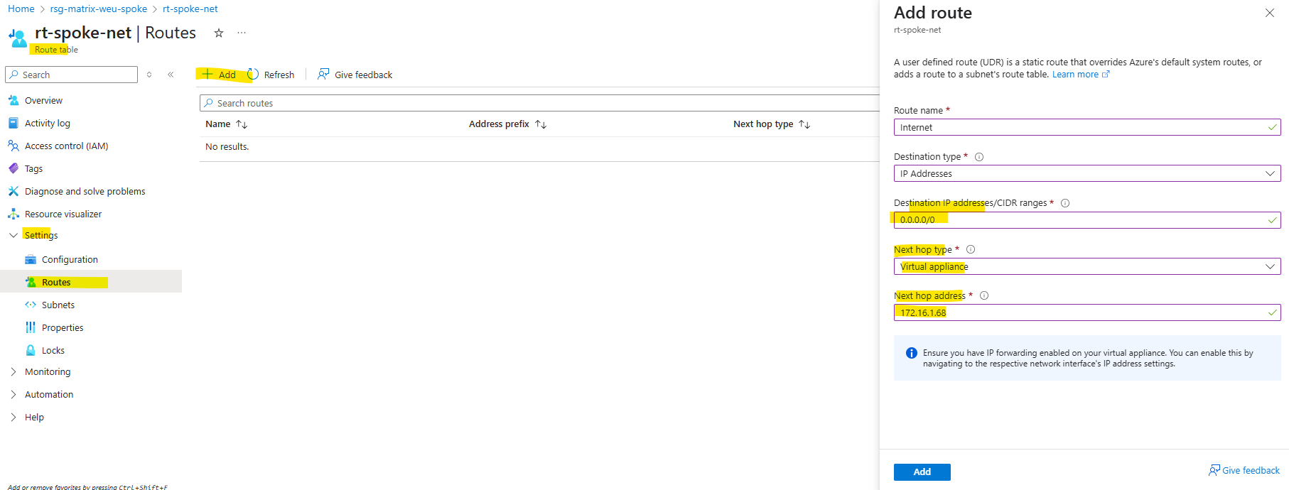
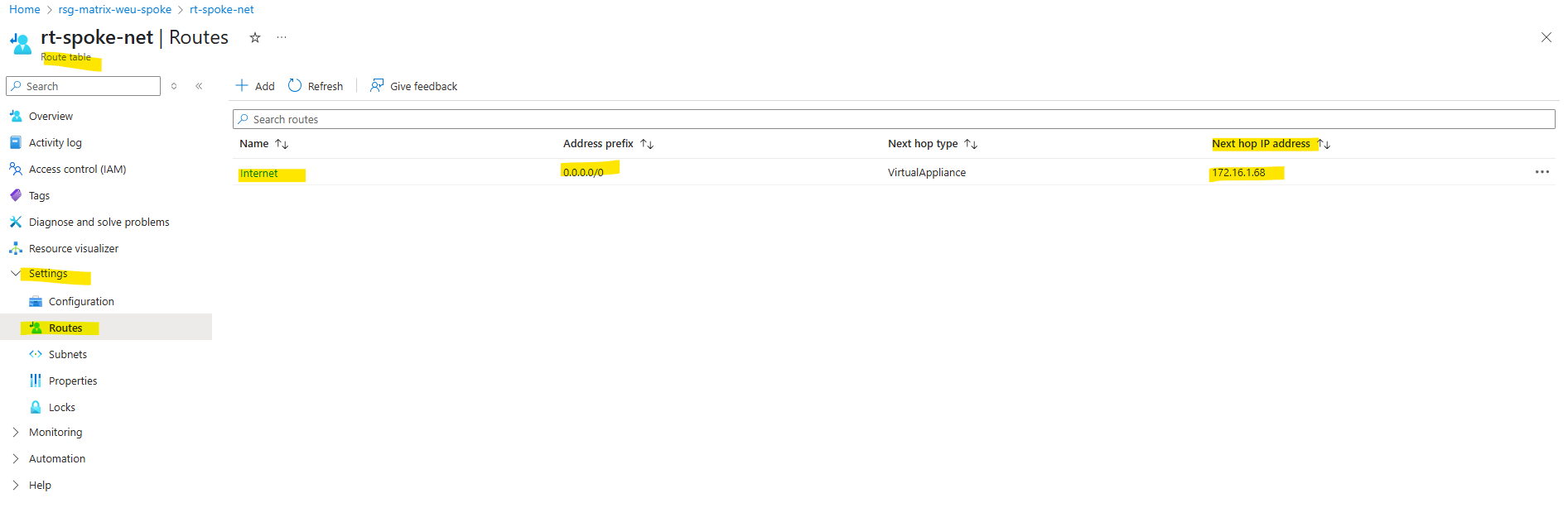
We now need to add a new route for the Internet where the next hop is the internal IP address of our Azure Firewall.
When creating a route for outbound and inbound connectivity through the firewall, a default route to 0.0.0.0/0 with the virtual appliance private IP as a next hop is sufficient. This will take care of any outgoing and incoming connections to go through the firewall. As an example, if the firewall is fulfilling a TCP-handshake and responding to an incoming request, then the response is directed to the IP address who sent the traffic. This is by design.
!! Note !!
In Azure, here VNet peering fully supports using an internal IP address from the peered hub network as a routing next hop. That means a firewall or router VM running in the hub VNet can be referenced directly in a Spoke VNet’s route table, no load balancer required.
In GCP, here VPC Network Peering (and even NCC spokes) blocks the use of a VM’s private IP in another VPC as a next hop. Instead, Google requires an internal passthrough load balancer (ILB) to act as the routing target for shared hub appliances.
This makes Azure more flexible for centralized routing architectures, while GCP enforces stricter routing boundaries between VPCs.
About how to configure this in GCP, you will see in my post here https://blog.matrixpost.net/mastering-gcp-virtual-machines-part-9-outbound-internet-access/#ilb.
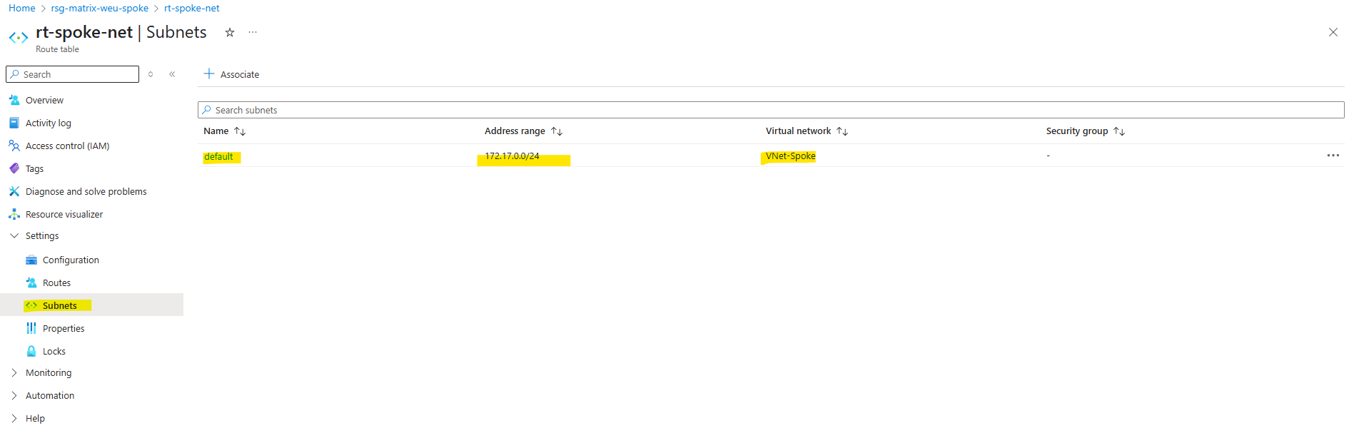
So far the new route table is not assigned to any subnets and therefore also not to our new virtual machine.
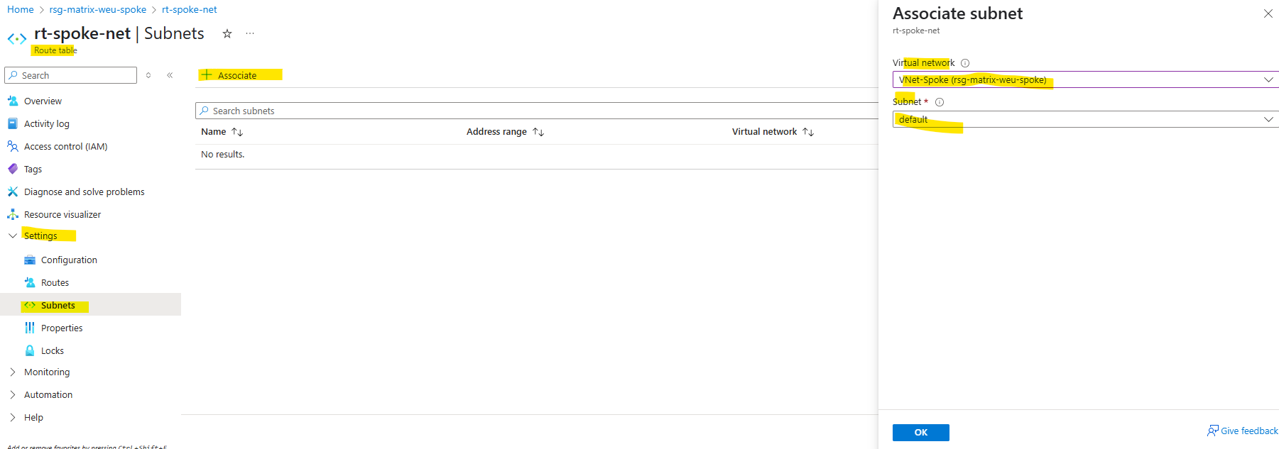
We now need to assign this new route table to the default subnet of the spoke virtual network where our virtual machine (workload) is running.
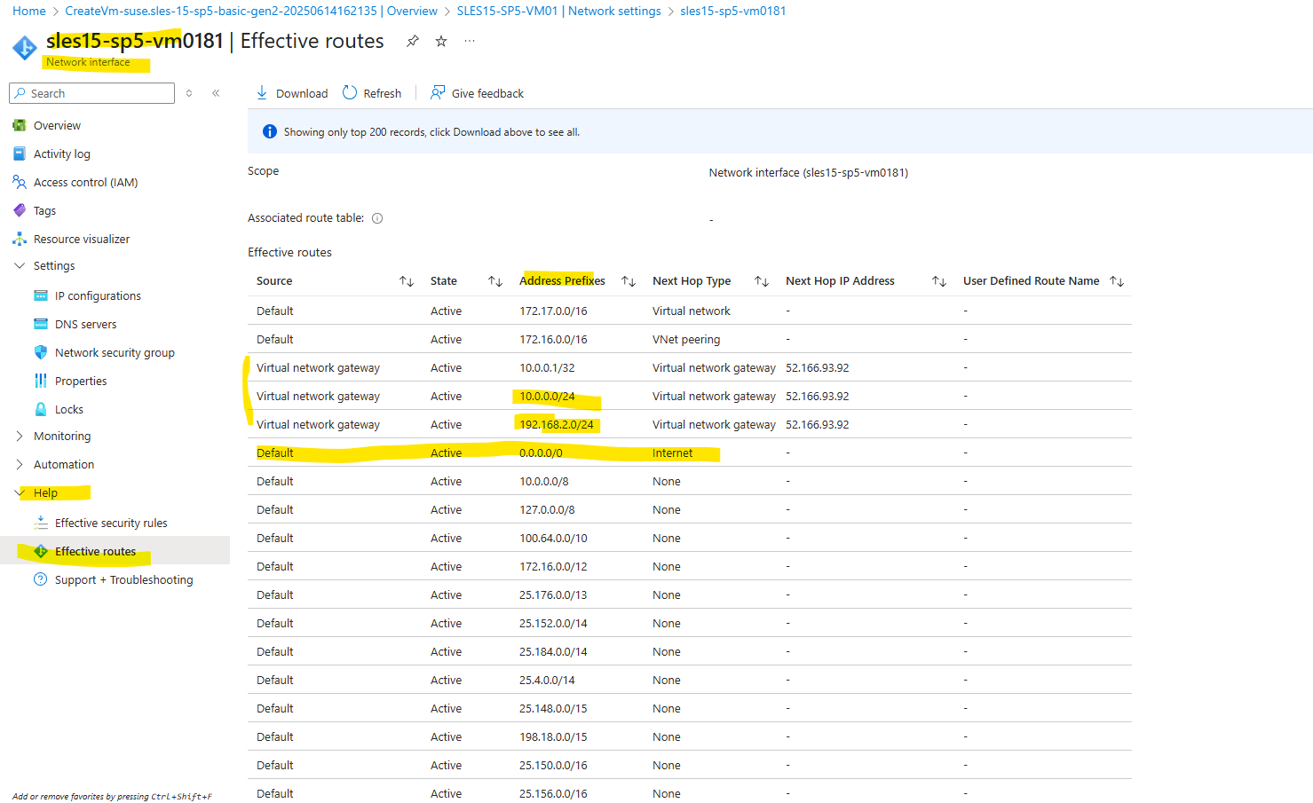
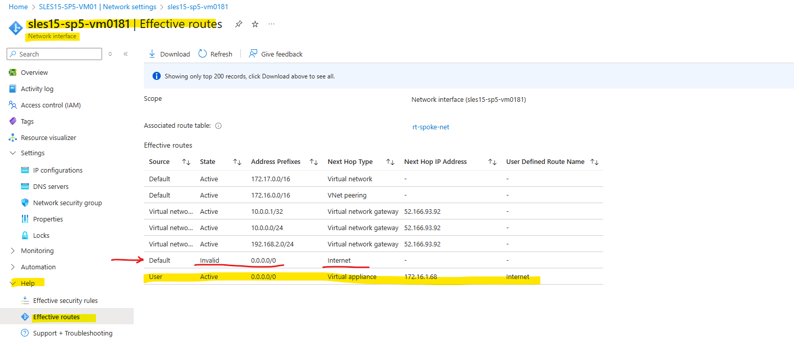
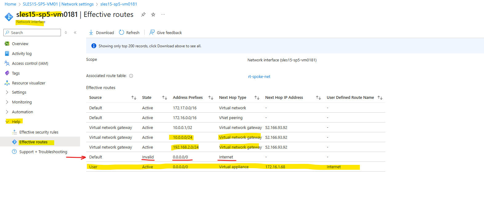
When we now check again the effective routes for the virtual machine (on the network interface), we can see that now the route for the Internet is set with the next hop to the internal IP Address of the Azure Firewall.
We can also see, that the route set by the default outbound access for VMs in Azure is now marked as invalid.
Because so far we not have configured any rules on the Azure Firewall, outbound traffic is currently not allowed for our virtual machine and the previous test.
This test to see the public IP address which is used to access resources on the Internet now will fail as shown below.
# dig TXT +short o-o.myaddr.l.google.com @ns1.google.com
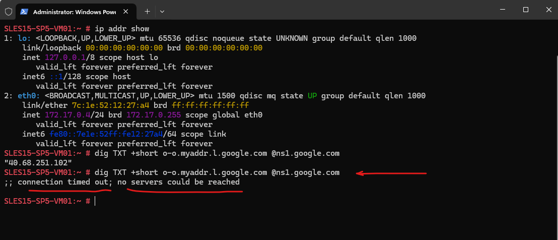
So the next step is to configure the Azure Firewall to allow outbound Internet traffic for our virtual machine or in general for the subnet it is running in.
For the test by using the dig command we need to allow at least DNS UDP 53 outbound to the Internet.
Configure Azure Firewall Rules to allow Traffic
To configure the rules for the Azure Firewall, click below on the Azure Firewall policy.
On the Azure Firewall Policy we can add a rule collection and rule to create Network rules (SNAT Source Network Address Translation) which will be used to allow outbound Internet traffic.
Below I will add two new rules, first to allow HTTP traffic and second DNS traffic to the Internet from the spoke virtual network and its default subnet.
Rule collections are sets of rules of the same type, DNAT, network, or application rules. Rule collection groups can include rule collections of various types.
DNAT (Destination Network Address Translation) rules will allow publish internal systems to the Internet
For the destination IP address to define any we can use the * as wildcard. The CIDR 0.0.0.0/0 isn’t valid here.
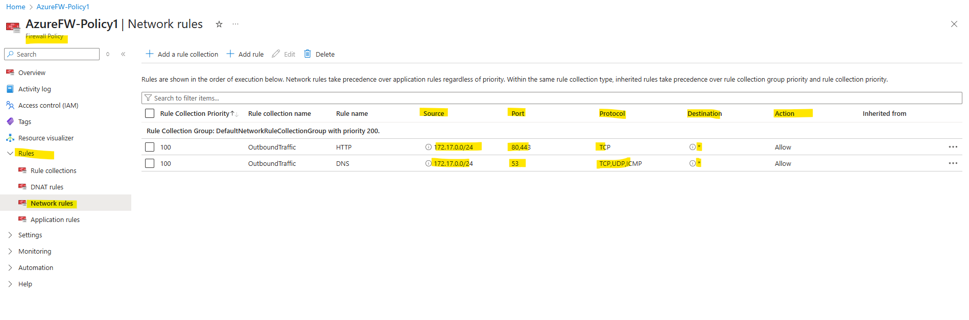
To see the public IP address which is used to access resources on the Internet by using the dig command, I was above adding the rule to allow outbound DNS traffic to the Internet.
# dig TXT +short o-o.myaddr.l.google.com @ns1.google.com

Looks good, from now on outbound internet traffic from the spoke virtual network is routed through the Azure Firewall which is running in the hub virtual network.
To publish internal services to the Internet, we can use the DNAT rules as mentioned. Below for example I have published the SSH daemon of my virtual machine running in the spoke virtual network.
For testing purpose I was restricting here access to my temporary public IP address (Source) assigned by my Internet provider.
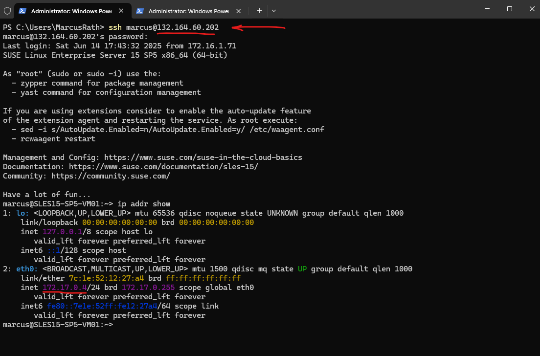
Actually I can access the virtual machine by using its private IP address 172.17.0.4 within the spoke virtual network which is routed through the IPSec site-to-site VPN tunnel to my on-premise network.
The Destination IP address below must be the public IP address of the Azure Firewall. The translated Address or FQDN is finally the internal IP of the workload you want to publish through the Azure Firewall, in my case here the private IP address of the virtual machine.
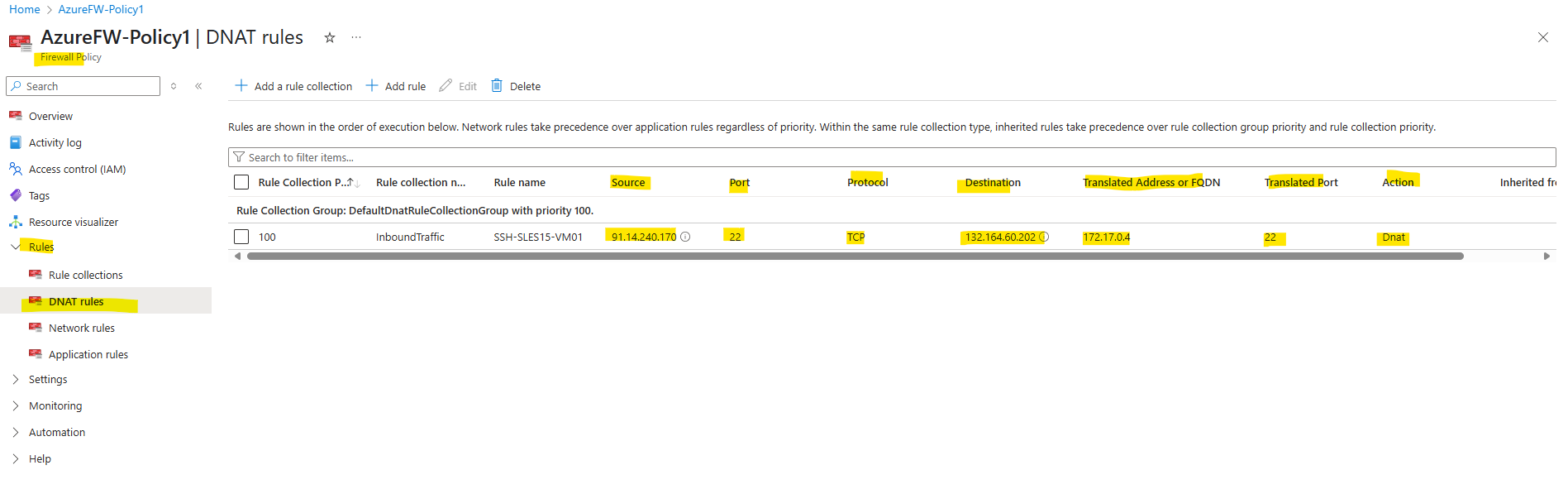
So from now on, I can also connect from external to the virtual machine by using the public IP address of the Azure Firewall on which I was publishing the SSH daemon of the virtual machine, but as shown restricted to the public IP address of my Internet provider.
We can also anytime adding further public IP addresses to the Azure Firewall to scale the internal workloads we want to publish to the Internet.
Determine Effective Routes for a Virtual Network Gateway where BGP is enabled
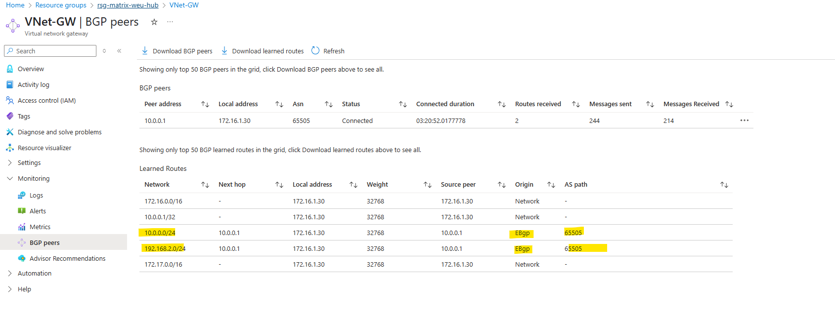
We can determine the advertised routes to our VPN gateway (in case BGP is enabled) in its menu under Monitoring -> BGP peers.
The below highlighted networks are my on-premise lab networks which where advertised by my on-premise VPN device (pfSense) to Azure.
Determine Effective Routes for a Virtual Machine (VMs NIC)
As already shown further above, the effective routes a virtual machine have, we can see on its network interface and here under Help -> Effective routes.
Below we can see the routes for the Internet 0.0.0.0/0 for which the next hop is the Azure firewall appliance and to my on-premise subnets (10.0.0.0/24 and 192.168.0.2/24) for which the next hop is the virtual network gateway and its configured S2S IPSec connection.
We can also see, that the route set by the default outbound access for VMs in Azure is now marked as invalid.
Firewall Management NIC and Forced Tunneling
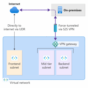
By default, Internet-bound traffic from your workloads and VMs within a virtual network is sent directly to the Internet.
Forced tunneling lets you redirect or “force” all Internet-bound traffic back to your on-premises location via S2S VPN tunnel for inspection and auditing. This is a critical security requirement for most enterprise IT policies. Unauthorized Internet access can potentially lead to information disclosure or other types of security breaches.
The following example shows all Internet traffic being forced through the VPN gateway back to the on-premises location for inspection and auditing.
About how to configure Azure Firewall in forced tunneling mode, you can read my following post.
ICMP Networking filtering rules will not work in Azure Firewall.
Network filtering rules for non-TCP/UDP protocols (for example ICMP) don’t work for Internet bound traffic
Network filtering rules for non-TCP/UDP protocols don’t work with SNAT to public IP addresses.
Non-TCP/UDP protocols are supported between spoke subnets and VNets.
Azure Firewall uses the Standard Load Balancer which doesn’t support ICMP for outbound NAT, the only supported protocols are TCP and UDP.
Microsoft exploring options to support this scenario in a future release.
Source: https://docs.azure.cn/en-us/firewall/firewall-known-issues#azure-firewall-standard
Links
Hub-spoke network topology in Azure
https://learn.microsoft.com/en-us/azure/architecture/networking/architecture/hub-spokeAzure Firewall known issues and limitations
https://docs.azure.cn/en-us/firewall/firewall-known-issuesAbout active-active mode VPN gateways
https://learn.microsoft.com/en-us/azure/vpn-gateway/about-active-active-gatewaysChoose the right Azure Firewall version to meet your needs
https://learn.microsoft.com/en-us/azure/firewall/choose-firewall-skuAzure Firewall pricing
https://azure.microsoft.com/en-us/pricing/details/azure-firewall/Microsoft Cloud Adoption Framework for Azure
https://learn.microsoft.com/en-us/azure/cloud-adoption-framework/Architecture best practices for Azure Firewall
https://learn.microsoft.com/en-us/azure/well-architected/service-guides/azure-firewallAbout forced tunneling for site-to-site configurations
https://learn.microsoft.com/en-us/azure/vpn-gateway/about-site-to-site-tunnelingConfigure forced tunneling using Default Site for site-to-site connections
https://learn.microsoft.com/en-us/azure/vpn-gateway/site-to-site-tunnelingAzure Firewall Management NIC
https://docs.azure.cn/en-us/firewall/management-nicWhat is Azure Virtual Network Manager?
https://learn.microsoft.com/en-us/azure/virtual-network-manager/overview