Step-by-Step Guide: Setting up a route-based S2S IPSec VPN Tunnel between Azure and On-Premise by using the Check Point GAiA Security Gateway for the on-premise VPN Device
In one of my last posts we saw how to set up the Check Point GAiA as Security Gateway appliance to provide outbound internet access and to publish internal services to the internet.
This time we will see step by step how we can set up an IPSec route-based site-to-site VPN tunnel between Azure and on-premise by using for the on-premise VPN device the Check Point GAiA Security Gateway appliance.
Usually for the on-premise VPN device I am using pfSense which is significantly easier and more transparent when it comes to setting up and managing IPsec VPNs, especially route-based.
pfSense is best when you want:
- Quick site-to-site IPsec
- Full control over IKE/IPsec settings
- Fast debugging
- Easy GUI
But when you need:
- Large-scale policy-driven VPNs
- Centralized control of 50+ tunnels
- Deep auditing, clustering, identity awareness
… Check Point earns its keep at the price of more hair-pulling to set up the tunnel.
About how to set up the tunnel in Azure step by step you can read in my following post. Here I was also configuring BGP on both sites to advertise automatically routes between both sites. In this post I will not configure BGP and therefore just configure static routes.
So also in Azure I was not enabling BGP this time. How to configure BGP in Check Point you will see in my following post.
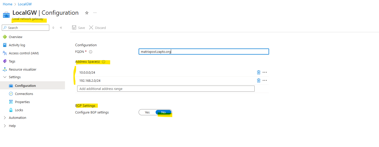
When we leave BGP disabled in Azure, we need to add our on-premise address space(s) we want to route through the tunnel by hand as shown below.
Address Space(s)
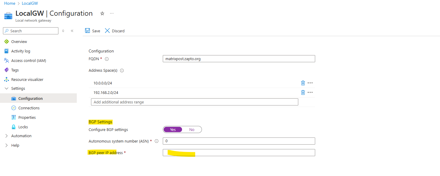
One or more IP address ranges (in CIDR notation) that define your local network’s address space. For example: 192.168.0.0/16. If you plan to use this local network gateway in a BGP-enabled connection, then the minimum prefix you need to declare is the host address of your BGP Peer IP address on your VPN device.
The mentioned minimum prefix we need to declare is the host address of our BGP Peer IP address in case we enable BGP.
This host address we then need to enter in the BGP peer IP address field below. The address space(s) we then can leave blank as the BGP protocol will advertise them from on-premise to Azure and vice versa.
Introduction
IPSec VPN setup consists of two negotiation phases, handled by the IKE (Internet Key Exchange) protocol:
- Phase 1 ==> Authenticate peers & establish secure channel ==> Protocol used: IKEv1/IKEv2 ==> Tunnel type: ISAKMP / IKE SA
ISAKMP stands for Internet Security Association and Key Management Protocol. It’s not an encryption protocol itself, instead it’s a framework that defines how to negotiate, establish, manage, and delete Security Associations (SAs) for protocols like IPSec.
IKE (v1/v2) is the protocol that uses ISAKMP to negotiate encryption/authentication.
- Phase 2 ==> Negotiate encryption for user traffic ==> Protocol used: IKEv1/IKEv2 ==> Tunnel type: IPSec / Child SA
IPSec in the phase 2 tunnel uses keys and SAs from IKE/ISAKMP to encrypt data routed through the tunnel.
ISAKMP uses UDP port 500 and in case the VPN device sits behind a NAT router like in my case, it will switch to UDP 4500 (NAT-T encapsulation).
Phase 1: IKE Security Association (IKE SA)
Establishes a secure control channel. Verifies identities (e.g., pre-shared key or certificate). Creates the IKE SA (secure tunnel for Phase 2 negotiation)
Negotiates:
- Encryption (e.g., AES)
- Hashing (e.g., SHA256)
- DH Group
- Lifetime (e.g., 86400s)
Phase 2: IPSec Security Association (IPSec SA / Child SA)
Negotiated inside the secure Phase 1 tunnel. Defines what traffic to protect (based on encryption domains or selectors). Creates the IPSec SA, which carries actual user traffic
Negotiates:
- IPSec encryption method (e.g., AES-GCM)
- Protocol: ESP (Encapsulating Security Payload)
- Lifetime (e.g., 3600s)
Star vs. Meshed VPN Community on Check Point
We will later create here a Star VPN Community to establish the tunnel with Azure.
In Check Point’s VPN architecture, the VPN Communities define how VPN gateways (Security Gateways) connect with each other, exchange encryption domains, and establish tunnels.
There are two main types: Star and Meshed. Choosing the right one depends on your network topology and communication requirements.
- Star ==> Central hub with multiple spokes (satellites) ==> HQ-to-branch or Azure as a central gateway ==> Satellite-to-satellite traffic is not allowed by default.
- Meshed ==> Every gateway can connect to every other ==> Fully connected sites, like data center peers
Domain-based VPN (aka Policy-based) vs. Route-based VPN (VTI-based)
Domain-based VPN (aka Policy-based)
- Uses encryption domains (defined networks behind each gateway)
- VPN rules are matched based on source and destination networks
- Tunnels are created only between the defined encryption domains
- Simpler setups where static networks are known
- Security policies are tightly scoped by subnets
Route-based VPN (VTI-based)
- Creates a Virtual Tunnel Interface (VTI) bound to a peer
- Tunnel is always up once established
- Routing table (static or dynamic) determines which traffic goes into the VPN
- No reliance on encryption domains
- Requires manual VTI configuration
NAT Traversal (NAT-T) Support by default
Check Point Security Gateways supports NAT-T (NAT Traversal) by default.
Even when unchecking the box below for NAT traversal under Gateway -> IPSec VPN -> VPN Advanced, the Check Point gateway will still using NAT-T if it detects that its sitting behind a NAT router.
NAT-Traversal is enabled by default when a NAT device is detected.
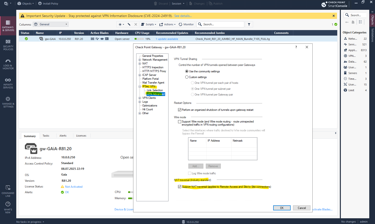
NAT Traversal (NAT-T) allows IPSec VPN traffic to pass through a NAT device (e.g., Fritz!Box like in my case) by encapsulating ESP (IP protocol 50) traffic inside UDP port 4500.
This is crucial because:
- ESP is not NAT-friendly
- Many NAT routers cannot handle IP protocol 50 (ESP) or perform port-preserving NAT
- NAT-T ensures VPN works by wrapping ESP in UDP/4500
Check Point automatically enables NAT-T when:
- The peer is behind a NAT device
- Or Check Point itself is behind NAT (e.g., behind a Fritz!Box)
During IKE Phase 1, NAT detection occurs:
- If either peer detects NAT in front of it, both switch to UDP/4500
For this post my Check Point gateway sits behind a Fritz!Box (NAT) and connecting (aka ike initiator) to an Azure Virtual Network Gateway which is not behind NAT and acts as responder only.
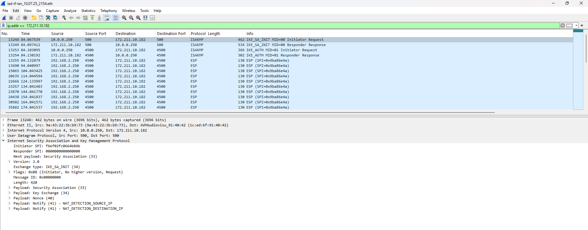
Below for example we can see the captured traffic on my FRITZ!Box during negotiating the VPN tunnel between the Check Point gateway (sitting behind my NAT router (FRITZ!Box)) and the Azure virtual network gateway.
About how to capture traffic on Fritz!Box you will find in my following post more https://blog.matrixpost.net/step-by-step-guide-setting-up-juniper-vsrx3-appliance/#capture_traffic_fritz_box.
Traffic captured on Fritz!Box’s internal LAN interface.
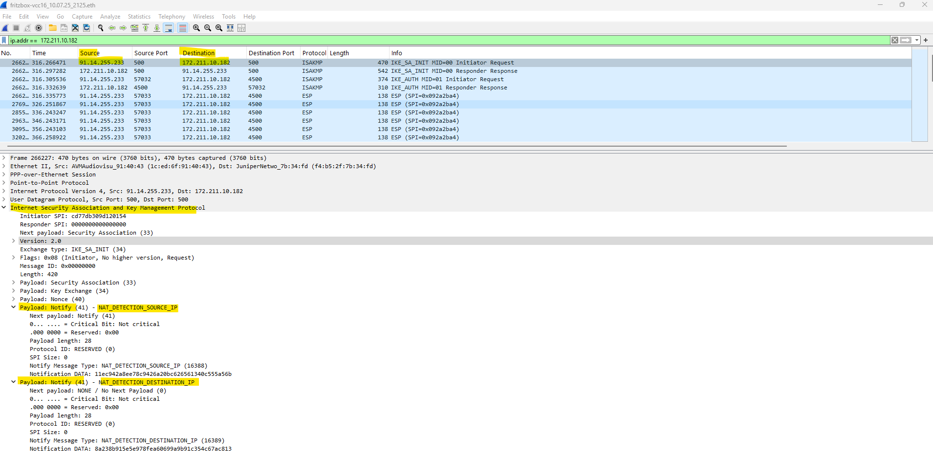
Traffic captured on Fritz!Box’s external WAN/internet interface.
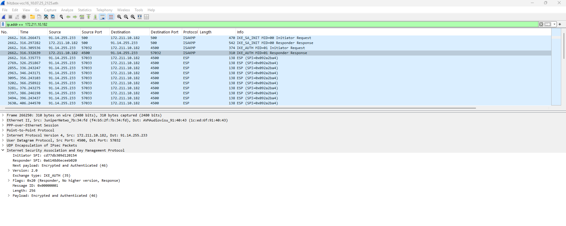
Above we can see that Check Point first initiates the IKE negotiation to the public IP address of the Azure virtual network gateway on UDP port 500.
NAT is detected by Azure because:
- The IKE packet from Check Point has internal IP + NATed external IP
- Azure replies with NAT-D payloads (NAT Discovery)
When NAT detection happens in IKEv2, the two parties exchange NAT-D payloads, which contain hashes, not raw IP addresses.
These are SHA-1 hashes, not plain-text IPs, therefore we cannot directly see Check Point’s internal IP address, in my case 10.0.0.250 (just seen above captured on the internal interface of Fritz!Box.
- NAT_DETECTION_SOURCE_IP → Hash of (source IP + source port)
- NAT_DETECTION_DESTINATION_IP → Hash of (destination IP + destination port)
Both sides detect NAT
- Check Point knows it’s behind NAT
- Azure knows Check Point is NATed
Both sides switch to NAT-T encapsulation. All further IKE and IPSec packets are sent via UDP/4500.
- Check Point encapsulates ESP in UDP/4500.
- Fritz!Box NATs this packet and forwards it to Azure
- Azure responds on UDP/4500, routed back via Fritz!Box
Next phase 2 (aka Quick Mode) negotiates the IPSec Security Association (SA) which defines:
- Encryption and hashing algorithms (ESP/AES/SHA)
- Proxy IDs (what traffic is protected)
- Key lifetime (typically 3600 seconds)
- Perfect Forward Secrecy (PFS)
- IPSec SPI and key material for ESP
Set up IPSec route based VPN in Check Point
First we need to enable the VPN feature (blade) in Check Point if not already done. In the SmartConsole double-click on the gateway under the Gateways & Servers menu and in the opened dialog under General Properties select IPSec VPN as shown below.
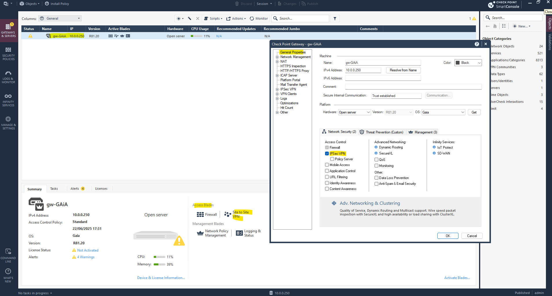
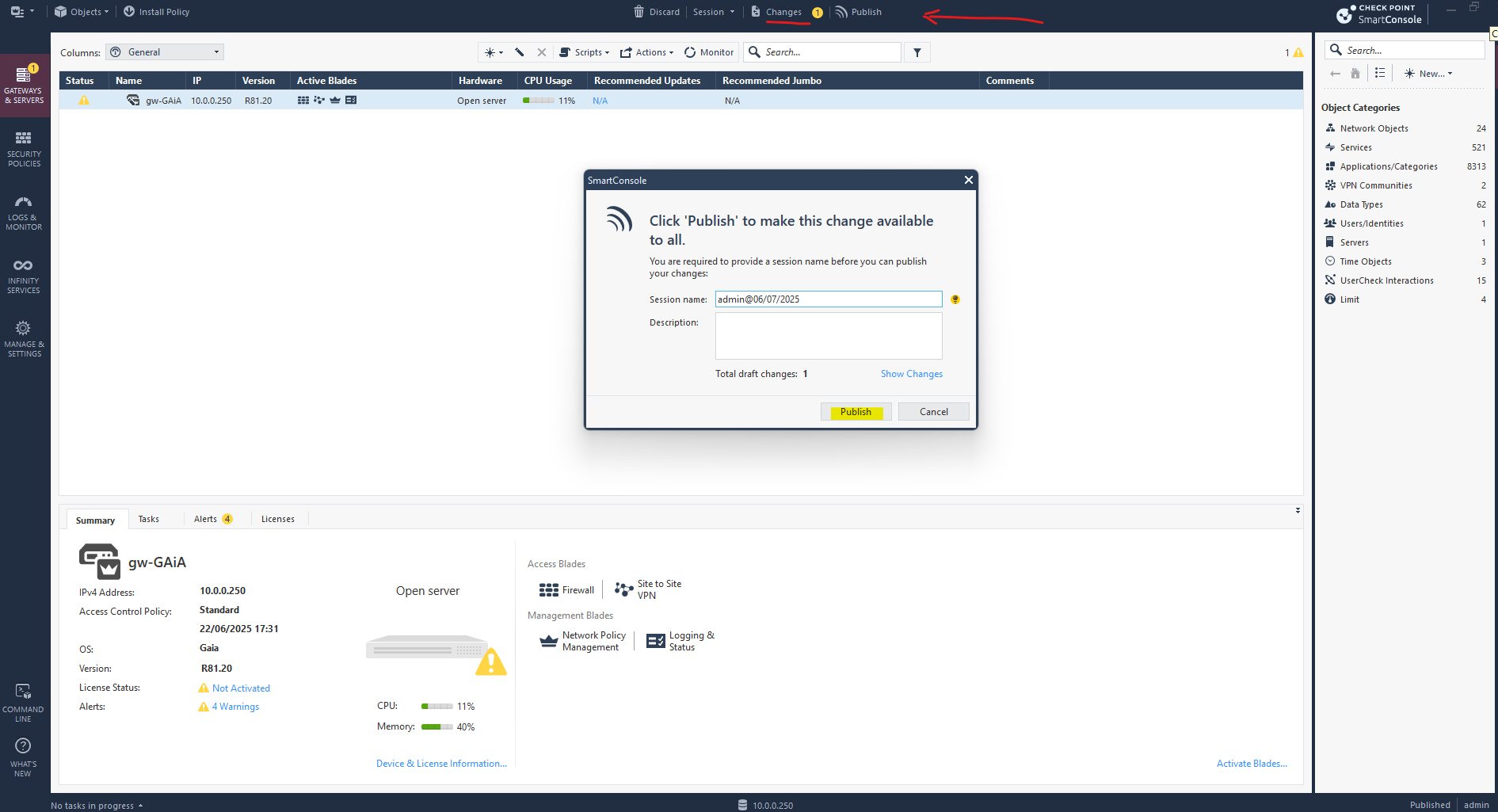
As usual in Check Point after changing something we first need to publish these changes before they becoming effective.
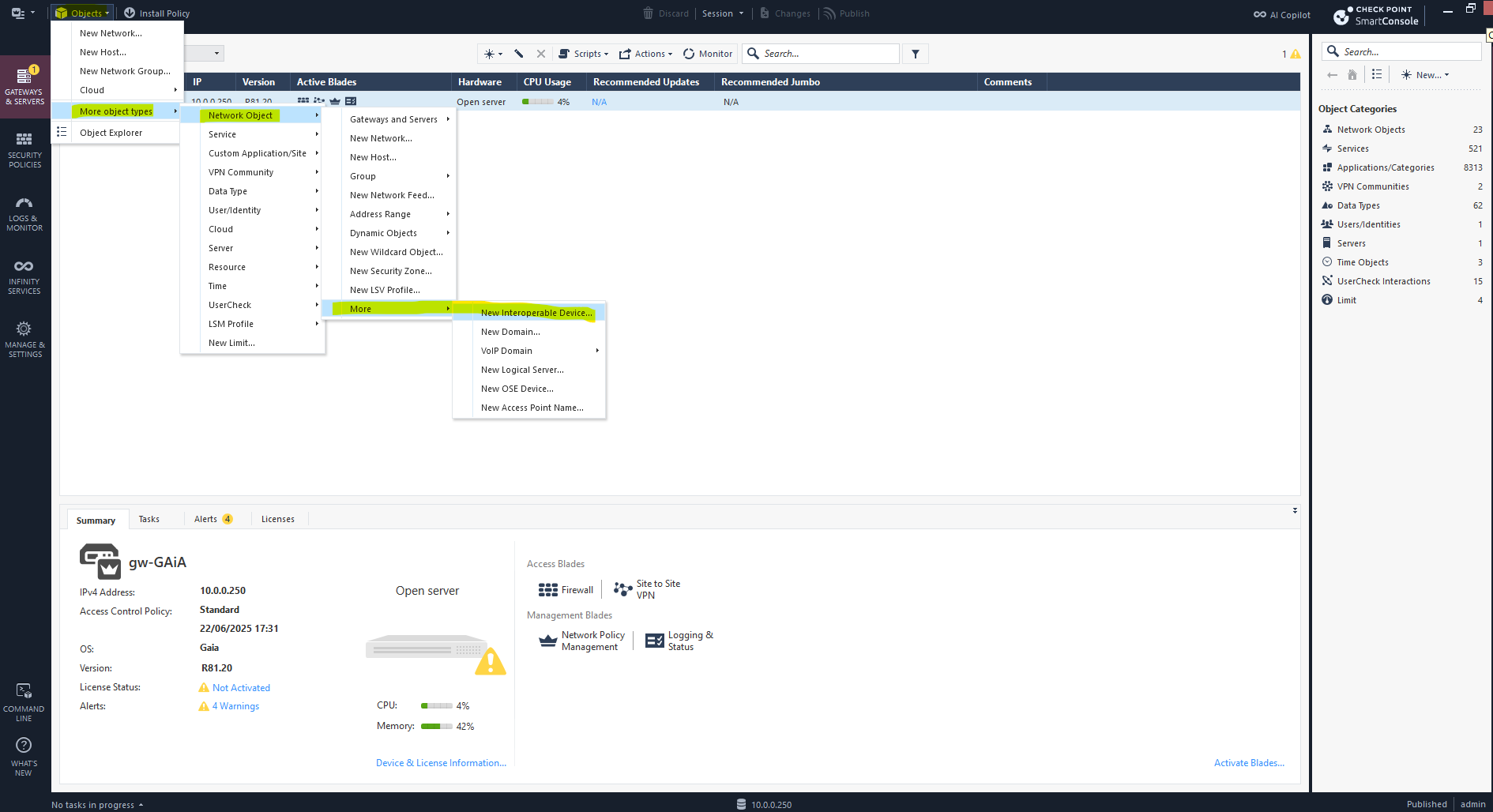
First I will create the Azure virtual network gateway (site) as new interoperable device in Check Point in order to create the VPN Community later.
To do so click on the top left bar on Objects -> More object types -> Network Object -> More -> New Interoperable Device …
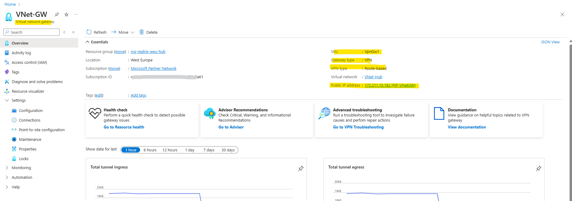
Enter a name and the public IP address of the Azure virtual network gateway which finally is the VPN device on Azure site.
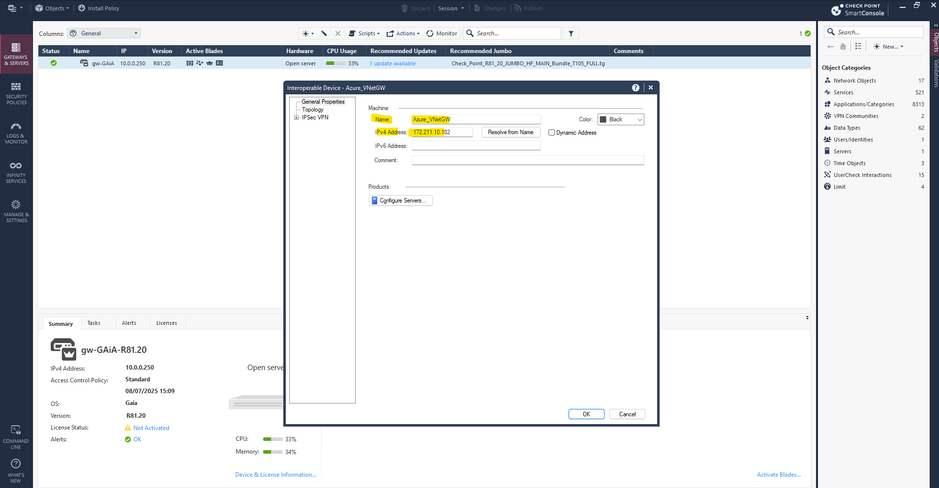
The public IP address we can check directly on the virtual network gateway blade in Azure.
Because on Check Point by default domain based (aka policy based) VPN takes precedence over route-based, we first need to create an empty (dummy) network group and assign it to our VPN domain on Check Point to force the route based VPN.
A VPN domain defines what networks are protected behind a gateway i.e., which IP ranges are considered internal and should be encrypted when communicating over the VPN.
In route-based VPNs, Check Point doesn’t use VPN domains to determine what traffic is encrypted. Instead, routing and the VTI interface control what gets encrypted and sent into the tunnel.
Check Point still requires a domain object to be configured, even if it’s empty because of internal architecture and validation in SmartConsole.
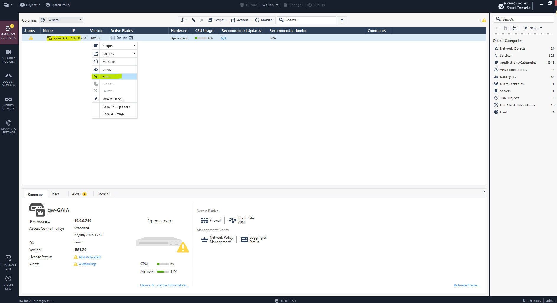
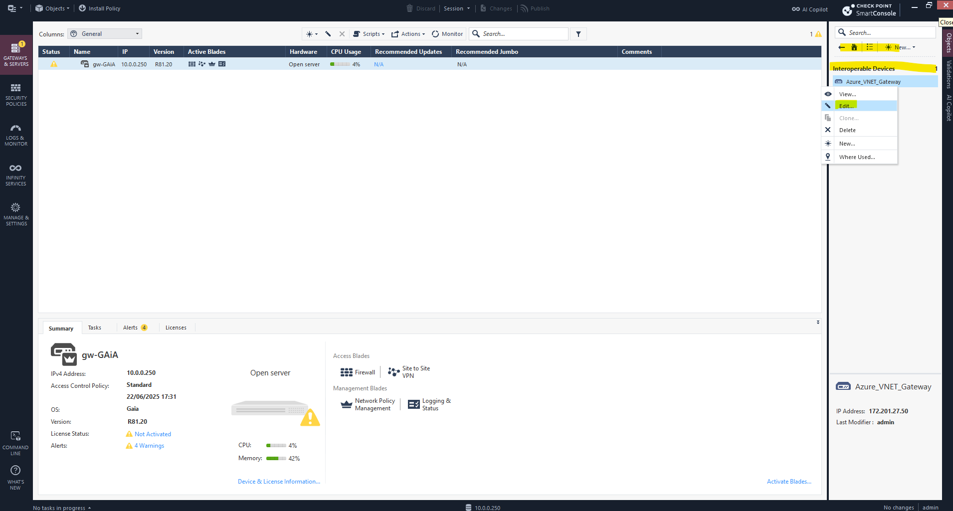
Therefore we need to open again the dialog for our gateway under the Gateway & Servers menu by double-click on or right-click and selecting edit as shown below.
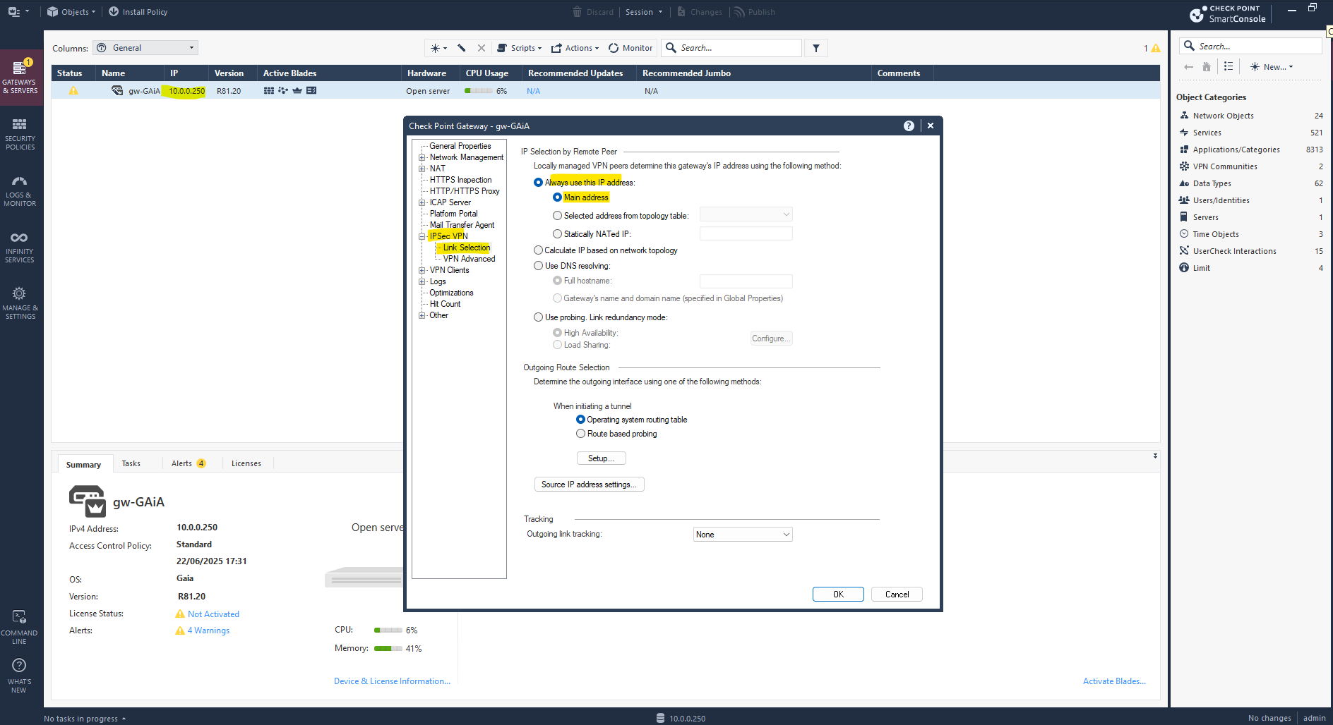
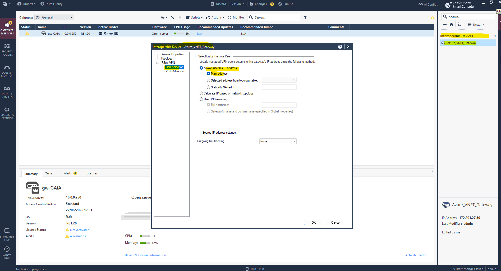
Under IPSec VPN -> Link Selection select Always use this IP address -> Main address which will then use the primary IP address of the gateway shown below on the Gateway & Servers panel, in my case 10.0.0.250.
The Main Address determines which IP address the gateway uses to identify itself during VPN negotiations, especially for outgoing IKE negotiations (Phase 1).
This is crucial when the gateway has multiple interfaces (e.g., internal, external, clustered IPs) or is behind NAT like in my case. Because my NAT router (FRITZ!Box) will NAT the outbound traffic to Azure, finally I can use here either the IP address assigned on the internal interface (Main Address) or of the external interface.
When Check Point is connected directly to the internet, we select here the IP address of the external WAN interface.
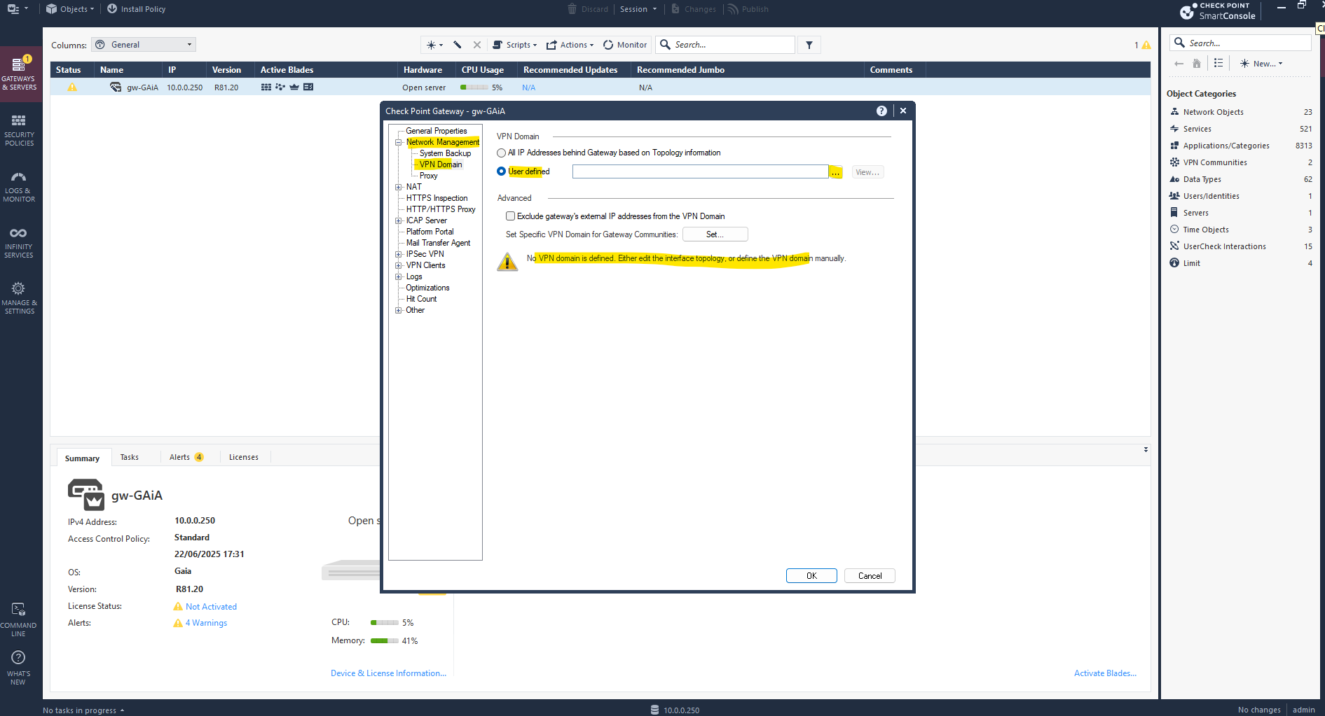
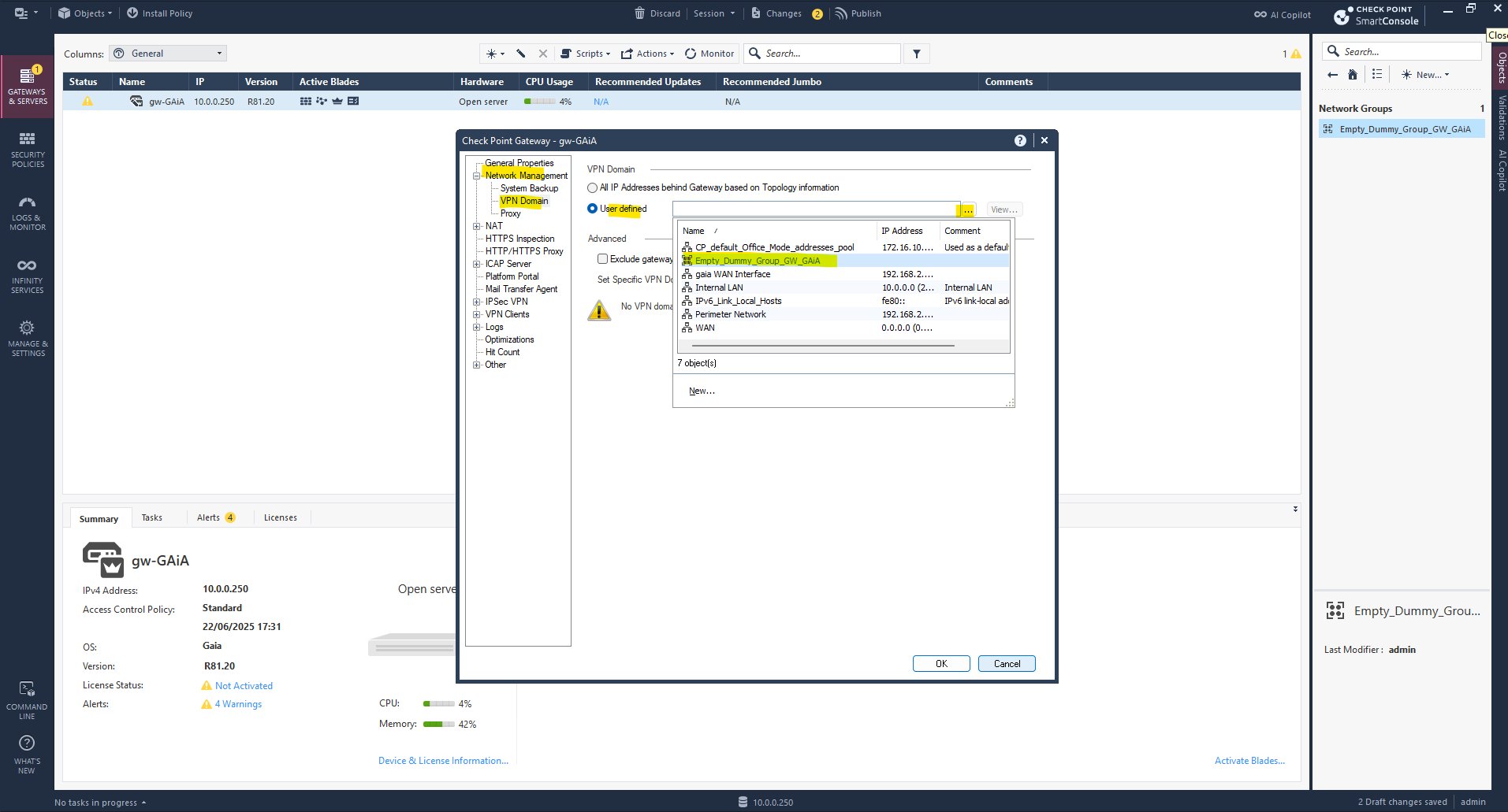
So now we will create our empty network group and set/define it for the VPN domain as mentioned under Network Management -> VPN Domain.
Click on the three dots to create a new one.
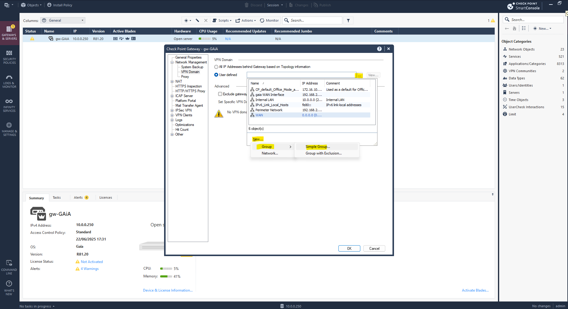
Click on New … -> Group -> Simple Group …
Enter a name for and click on OK.
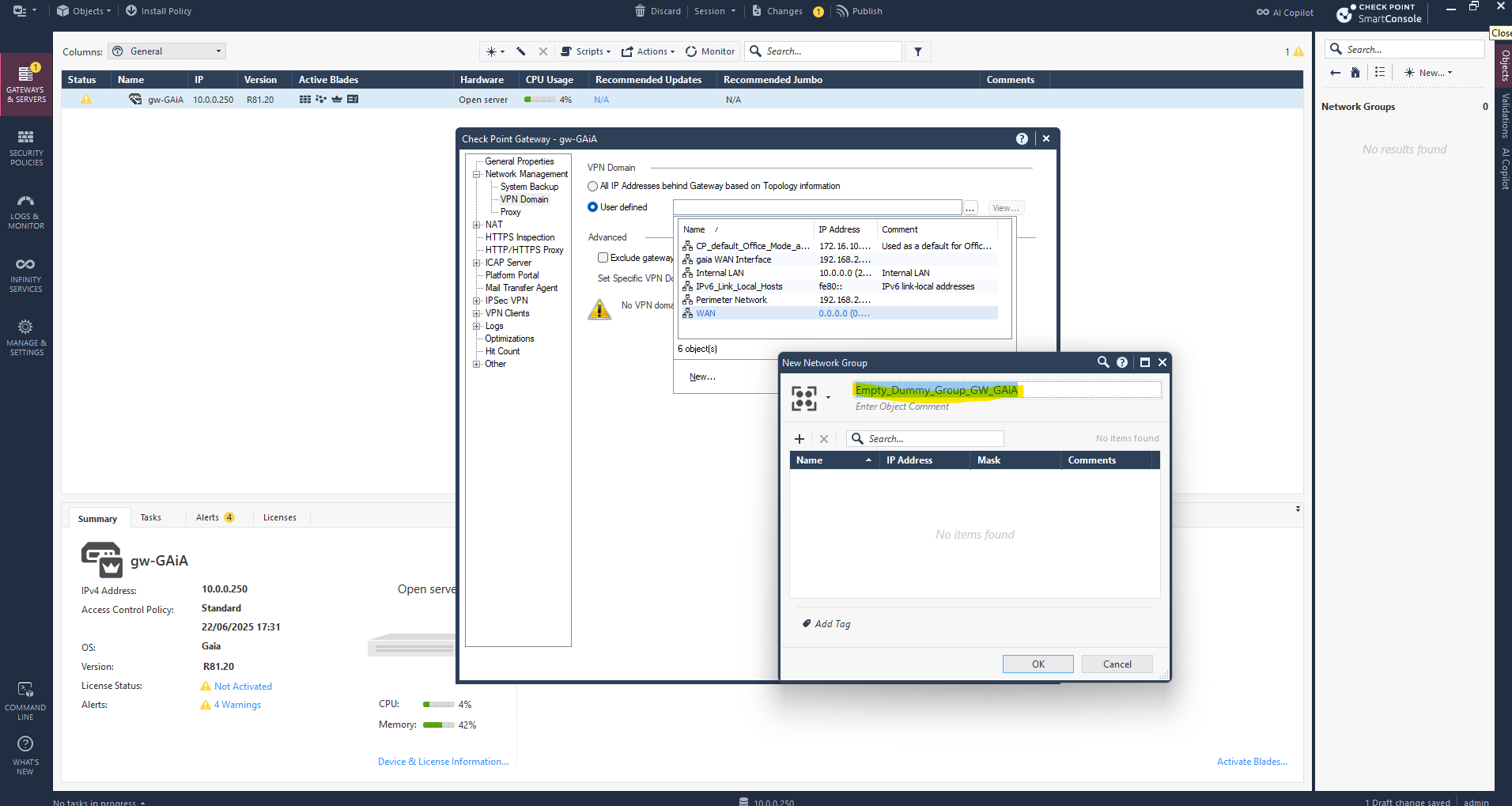
We can now select this empty group for our VPN domain to force the route-based VPN.
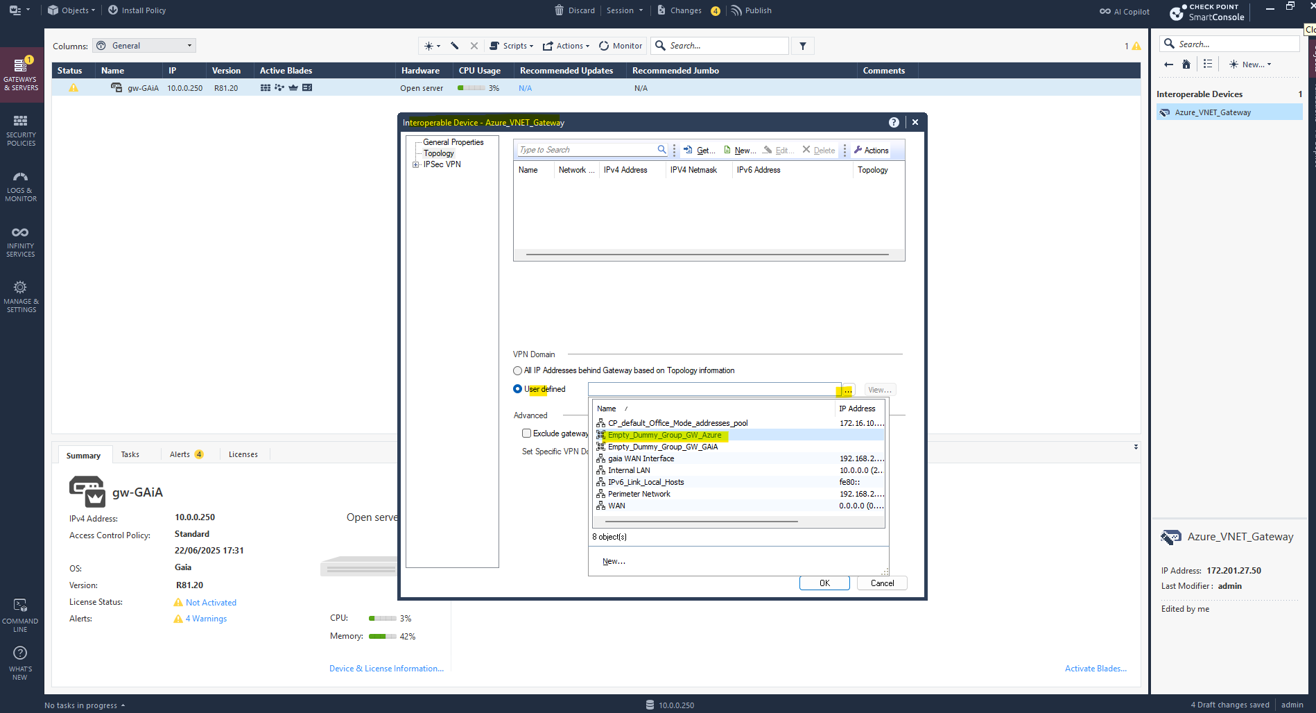
We must also create a new empty network group on our previously created Azure virtual network gateway object, in Check Point we added this as Interoperable Device.
We can find it again by either using the object explorer on the top left bar or on the right side bar.
Select Topology -> VPN Domain -> User defined. Click on the three dots to create a new network group.
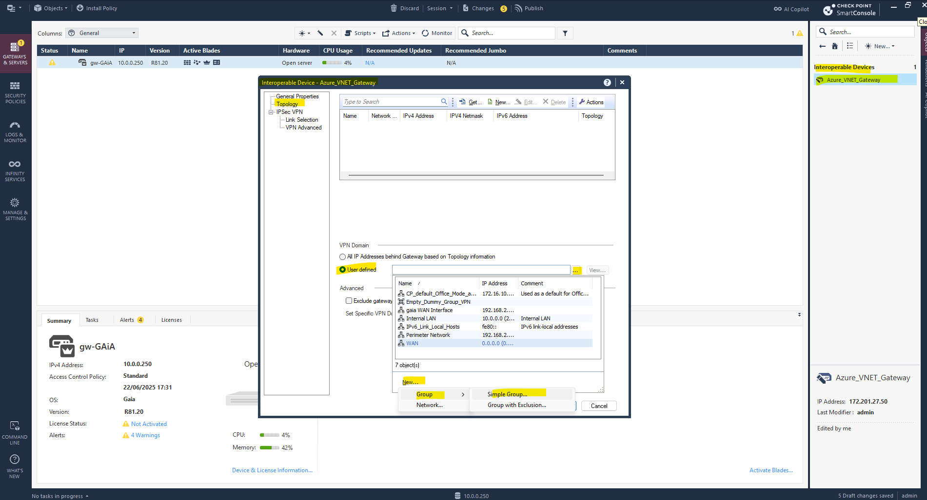
Enter a name for and click on OK.
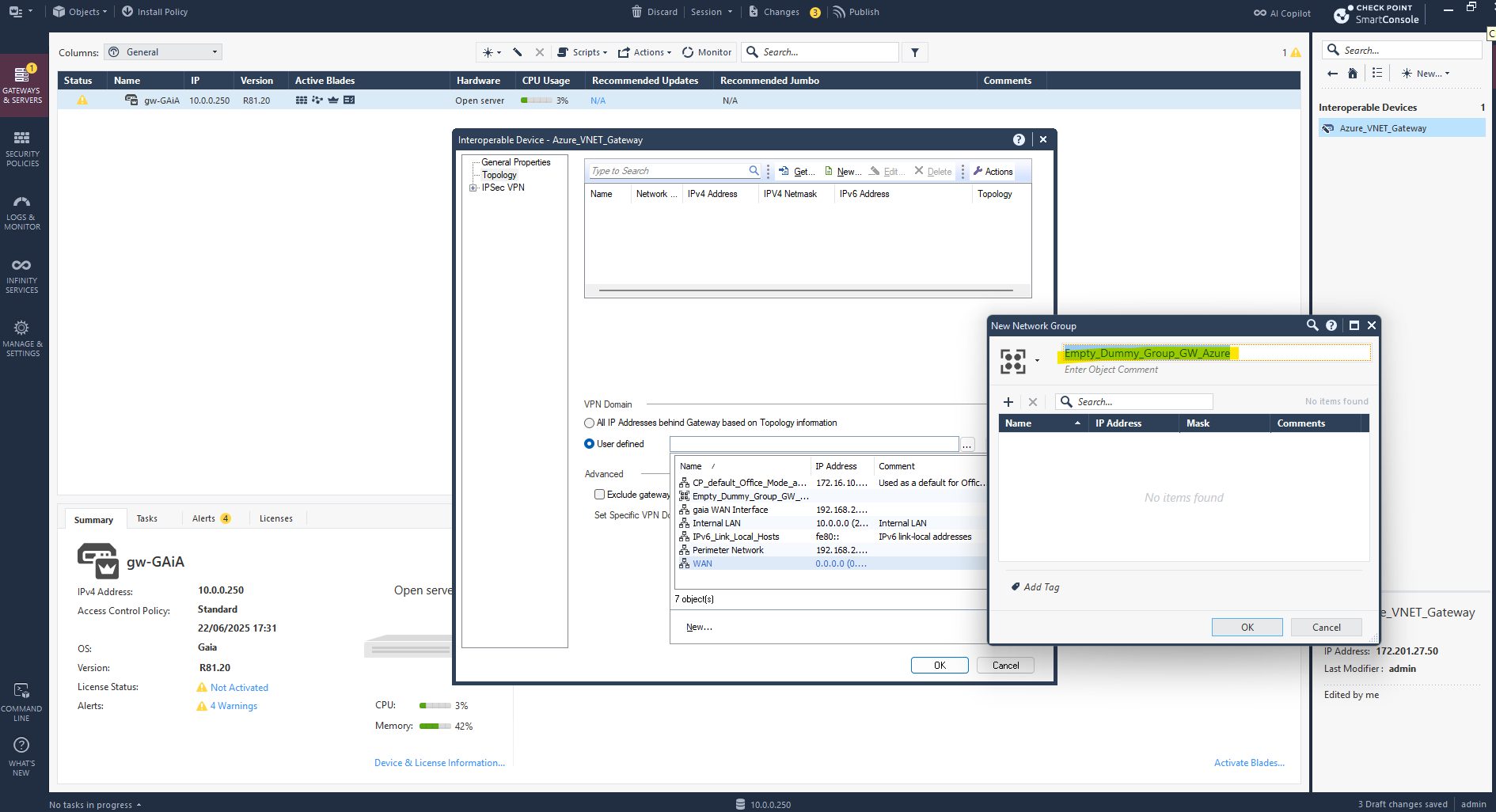
Then we can select the new empty network group for the VPN domain on the Azure Gateway.
For the Link Selection section we also need to leave the default settings with Always use this IP address -> Main address which finally is the public IP address of the virtual network gateway in Azure.
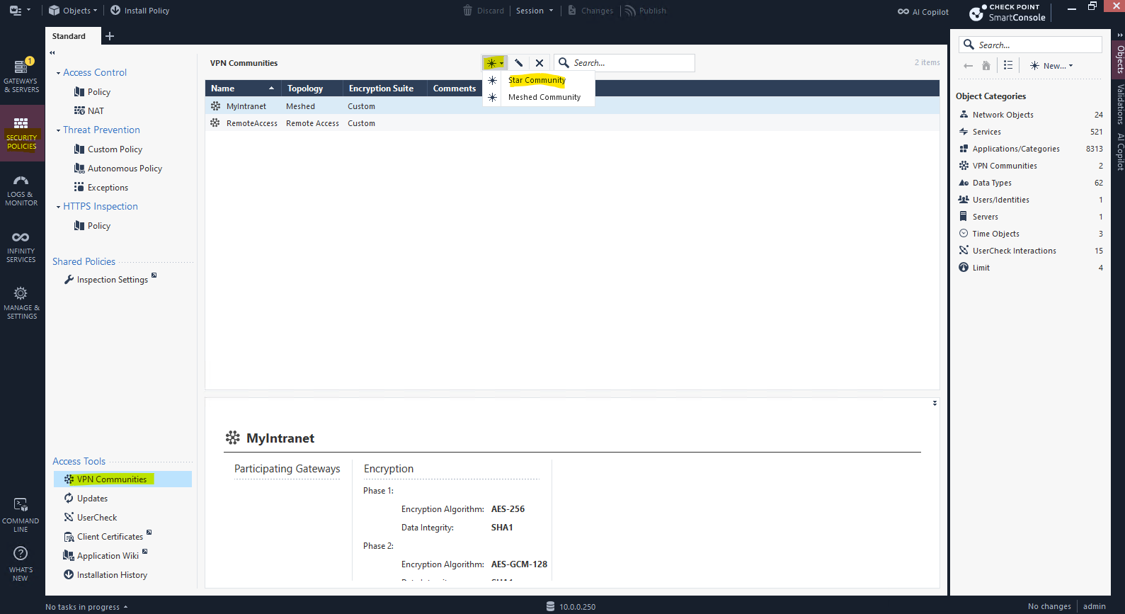
Next we need to create a new VPN Community. Therefore under Security Policies -> Access Tools -> VPN Communities click on the icon as shown below and select Star Community.
A VPN community in Check Point is as mentioned to the beginning a logical container that defines how VPN tunnels are built and behave between gateways. It groups VPN participants (Check Point gateways and/or third-party peers) and sets global VPN configuration parameters like encryption methods, shared secrets, and tunnel setup rules.
Enter a name for the new VPN Community.
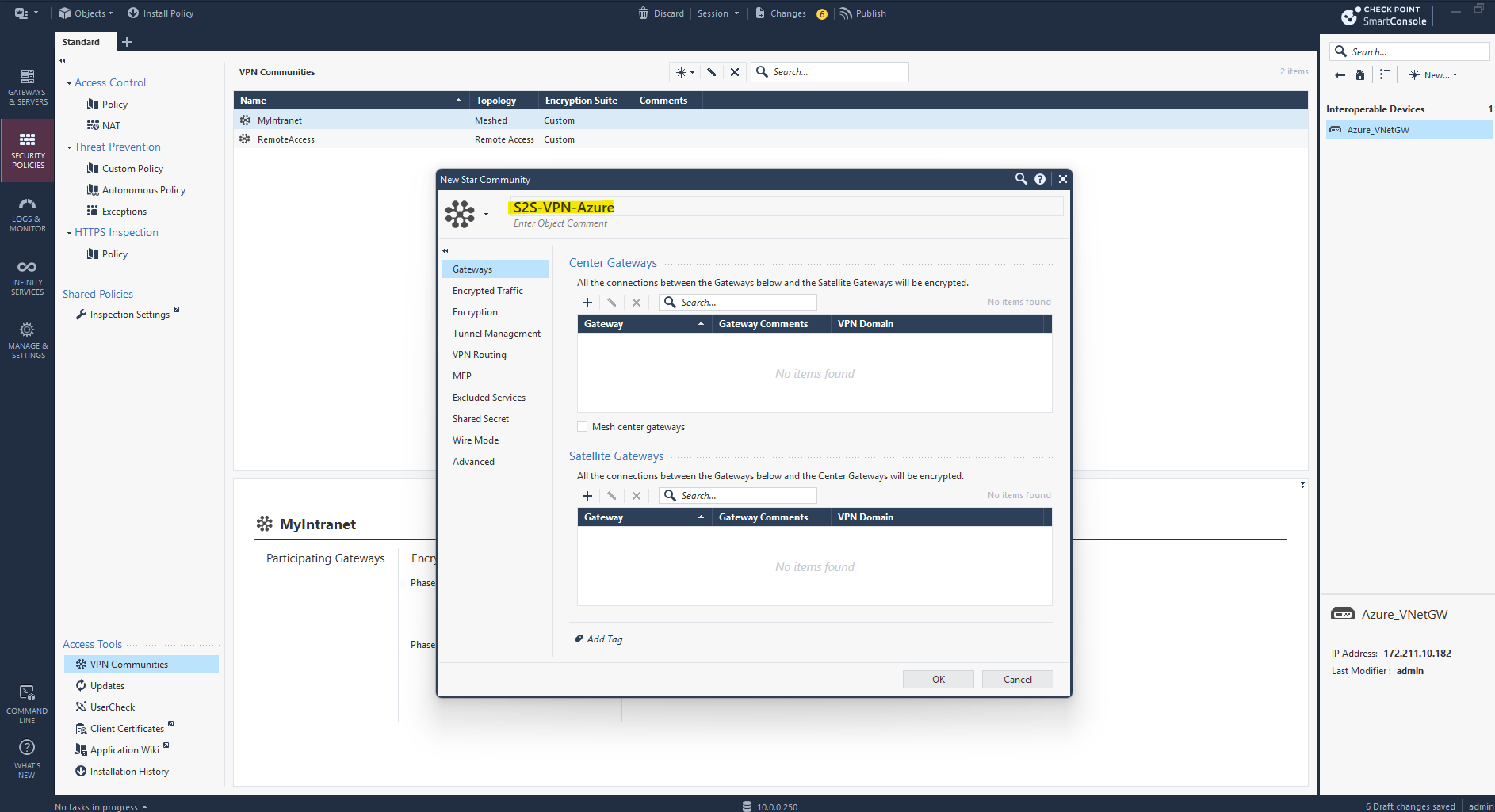
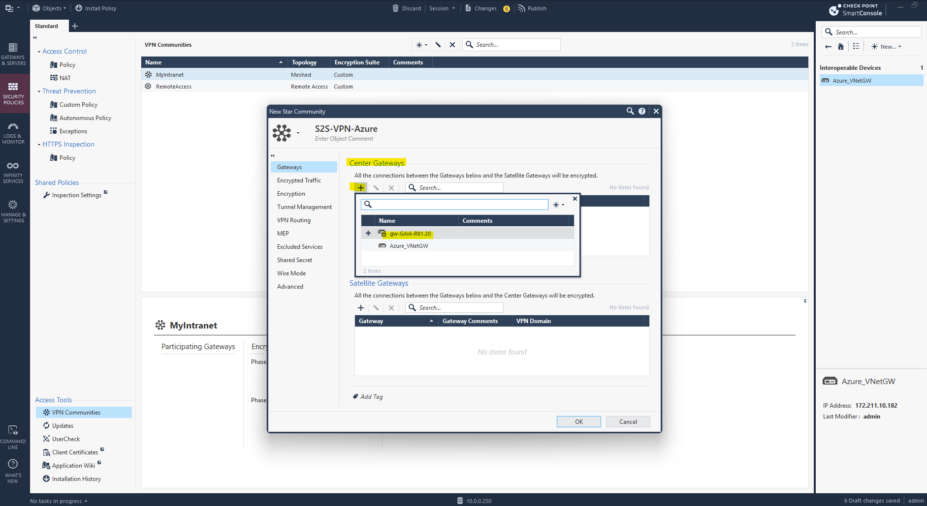
First add the Check Point gateway under Center Gateways.
Center Gateways (hubs) can connect to a large number of satellite gateways (spokes).
Satellite-to-satellite traffic is not allowed by default.When creating a meshed VPN Community in contrast, as mentioned every gateway can connect to every other ==> Fully connected sites, like data center peers.
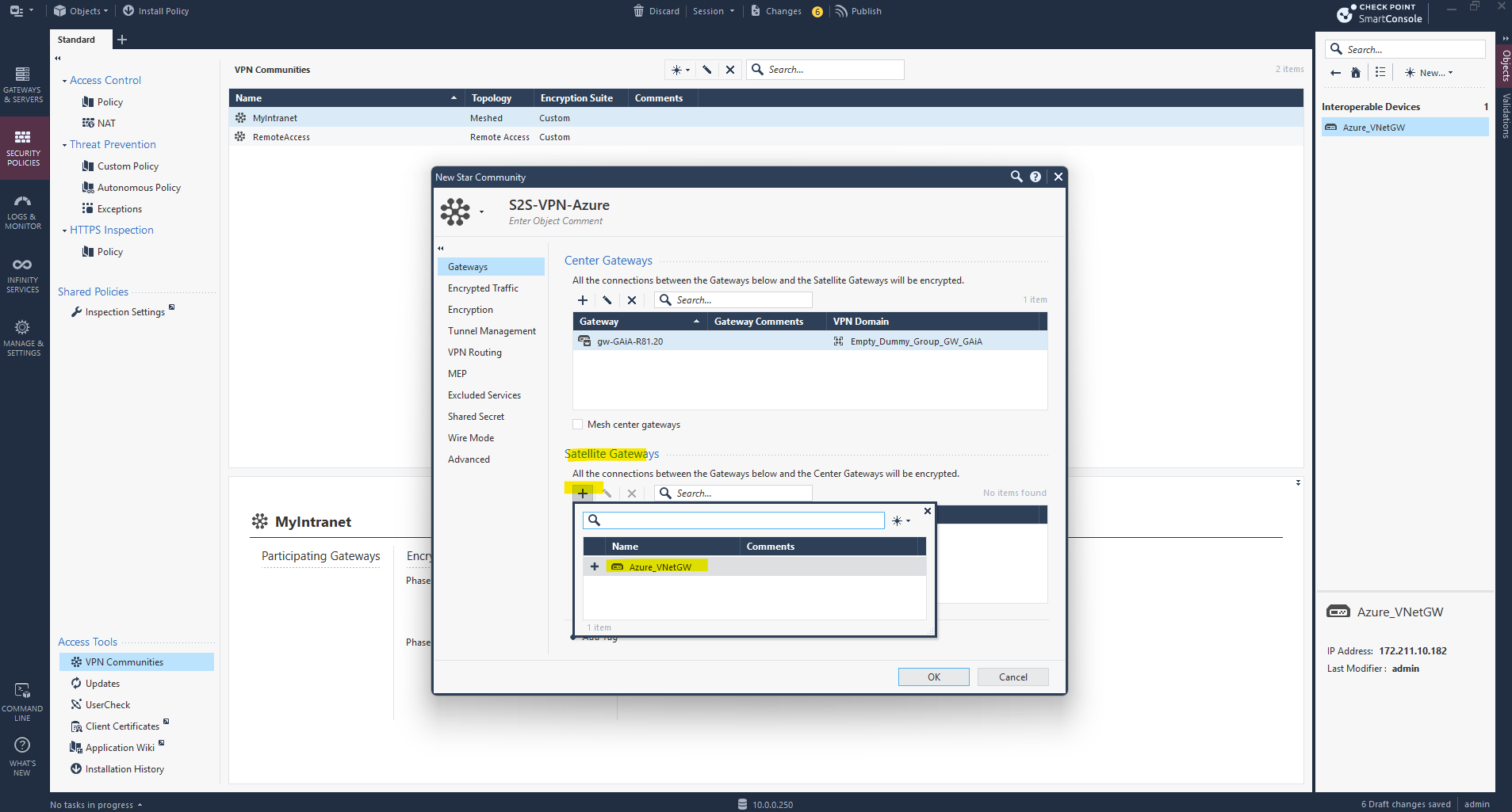
For the Satellite Gateway add the Azure virtual network gateway we previously created as new Interoperable Device.
Satellite Gateways are a concept used in Check Point’s Star VPN Communities in SmartConsole. They are the spoke gateways in a hub-and-spoke VPN topology, where the central gateway (the hub) controls or routes traffic between the spokes.
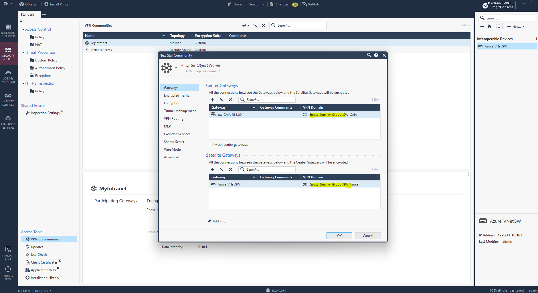
We can also see below that for both gateways our empty network groups are set as VPN domain.
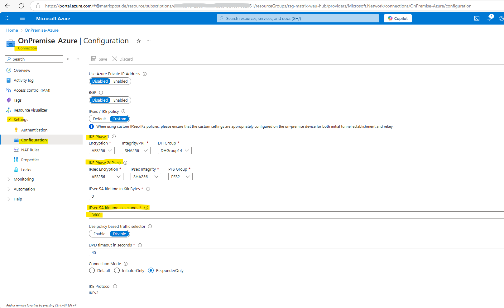
Under Encryption, we select IKEv2 only and adjusting the values according the configuration in Azure. Finally they must match on both sites.
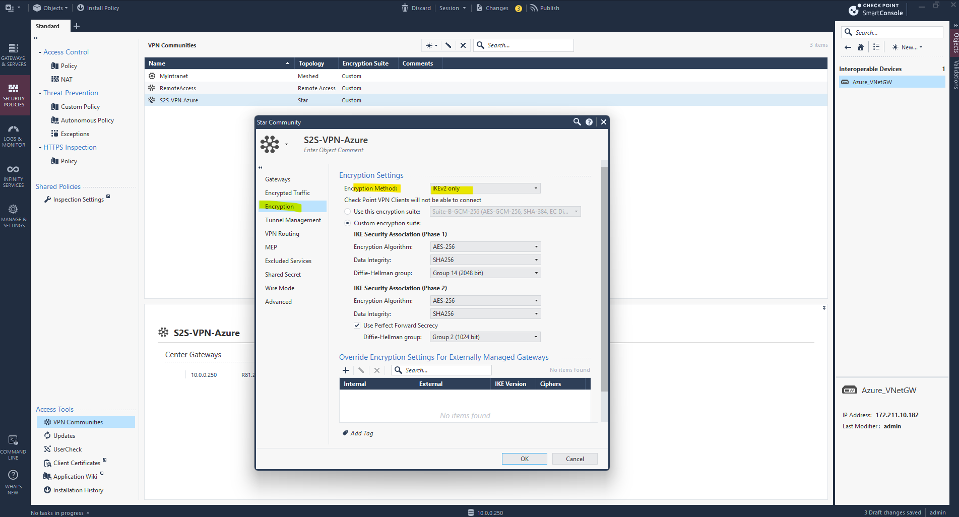
In Azure we can check these settings directly on the Connection, either under settings menu of the virtual network gateway or local network gateway blade.
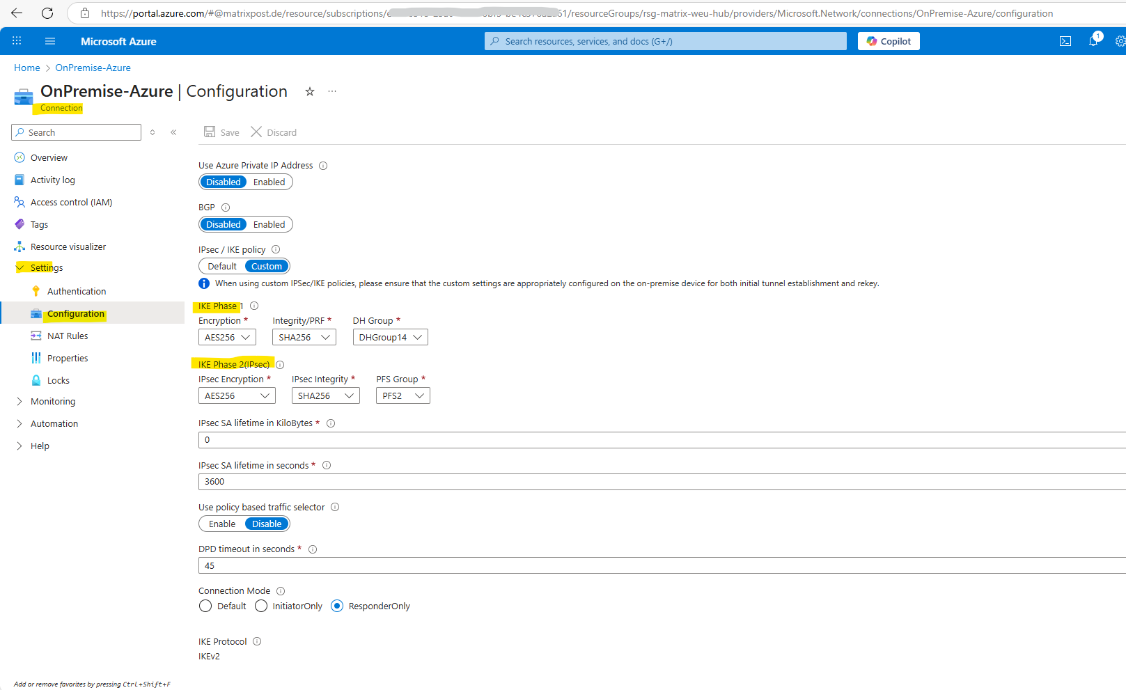
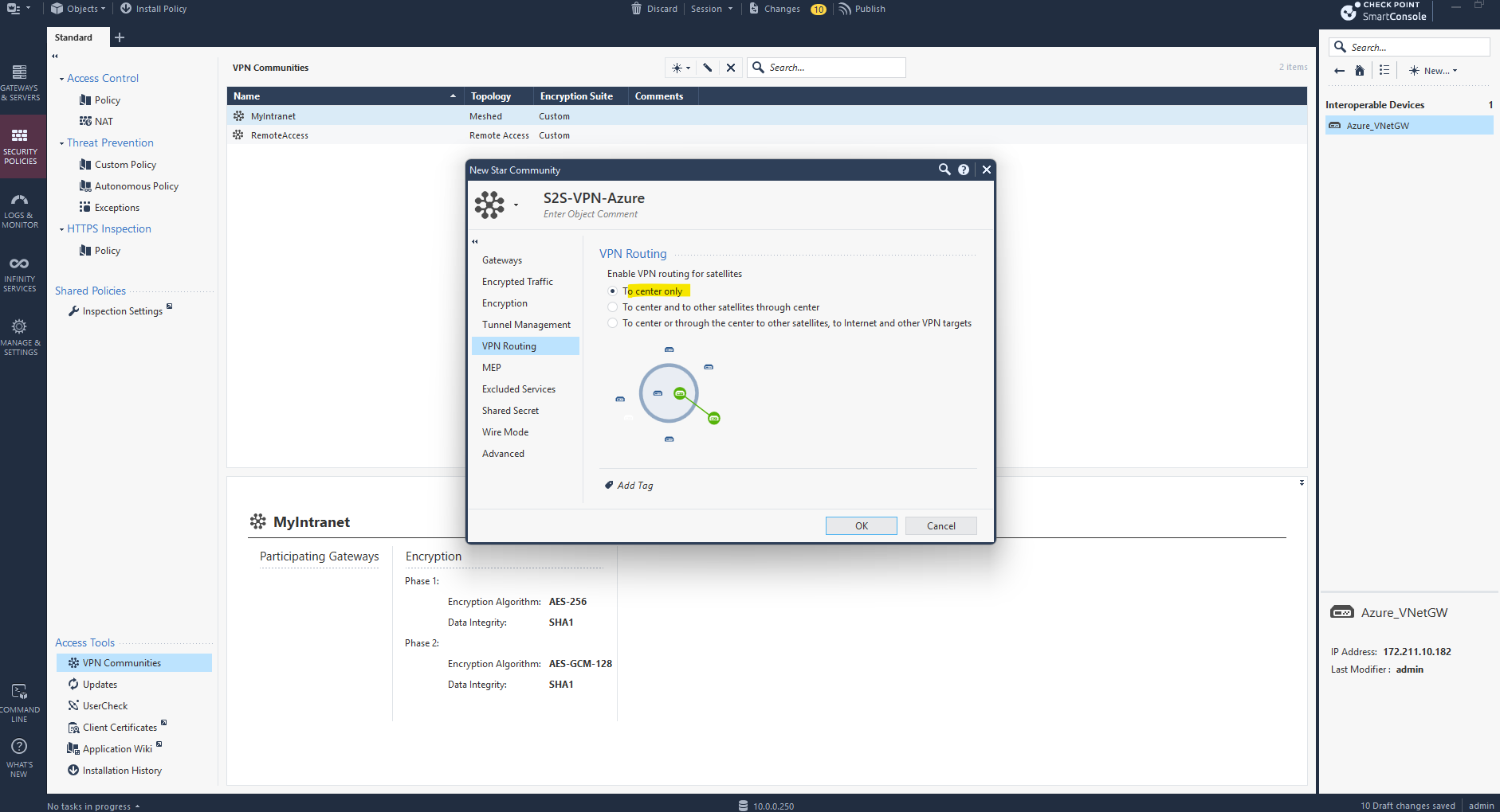
Under VPN Routing leave the default setting with To center only.
This determines how traffic is routed between satellite gateways. This setting ensures that Satellite gateways can only send VPN traffic to the center gateway(s).
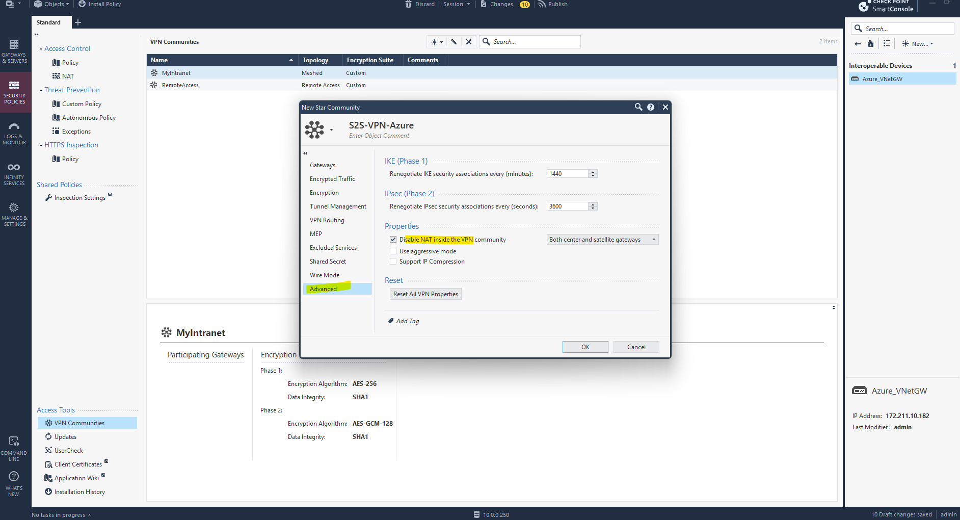
Further I will disable NAT inside the VPN community as I don’t have overlapping networks between Azure and my on-premise lab environment.
About how to use NAT when your networks overlaps you will find in my following post https://blog.matrixpost.net/pfsense-site-to-site-ipsec-vpn-same-subnet-on-each-site/.
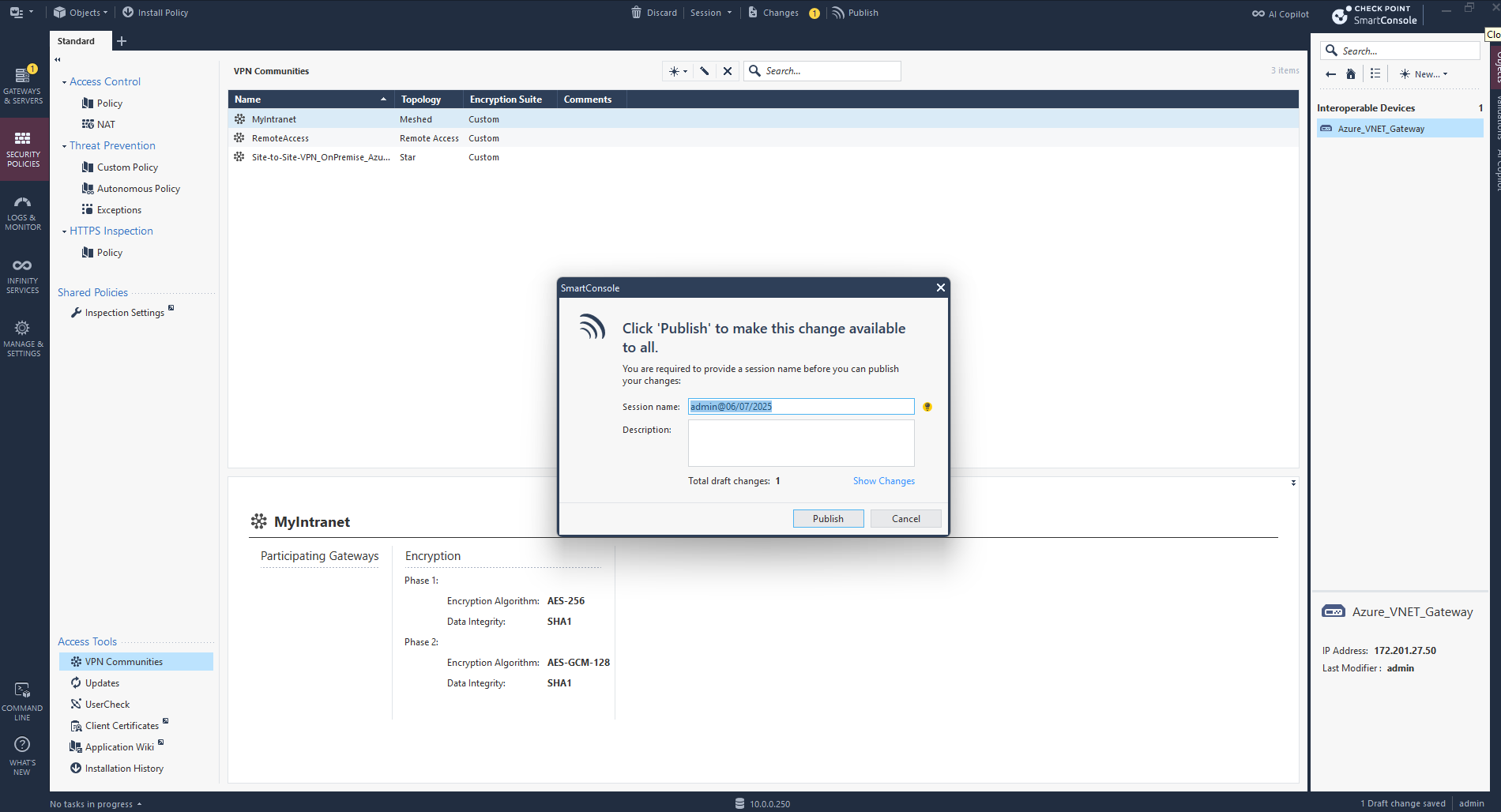
For the moment click on OK and publish the changes.
To configure the Tunnel Management on the VPN community, we first need to create the VTI interface.
A VTI is a “virtual cable” between the Check Point gateway and the VPN peer (Azure VPN Gateway in my case), over which you can route any IP traffic. It’s like a direct connection.
So instead of encrypting based on encryption domains (like in domain-based VPN aka policy based VPN ), a VTI allows traffic to be routed through the tunnel based on the routing table (static or dynamic).
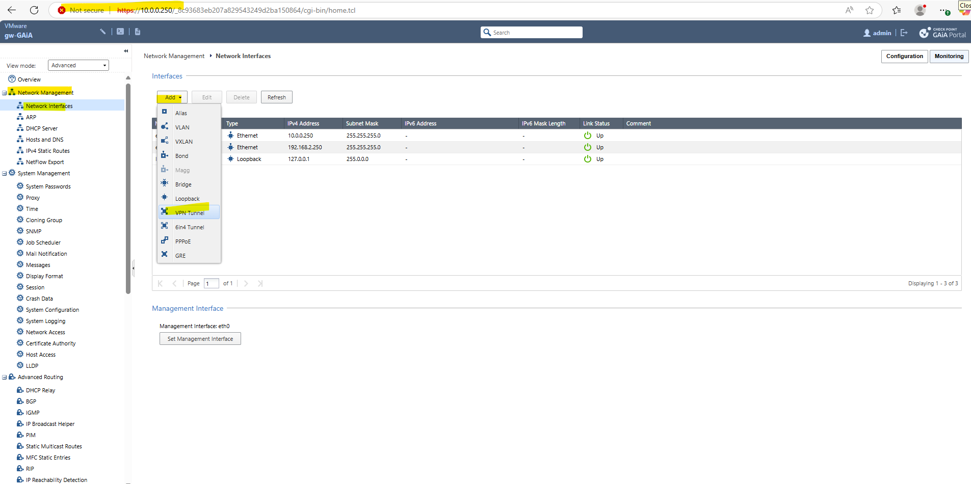
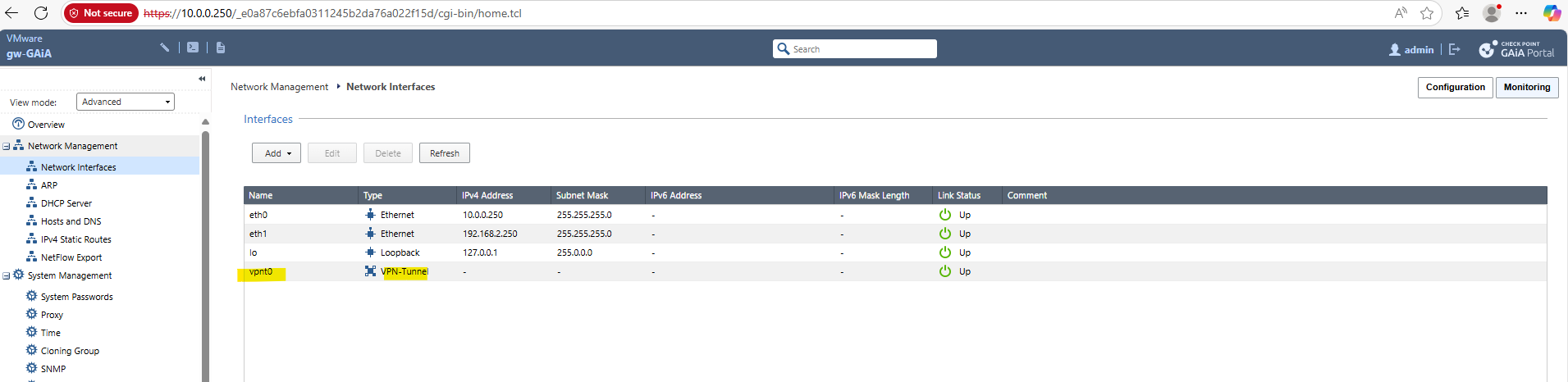
To create a VTI interface we need to login to the Gaia web portal.
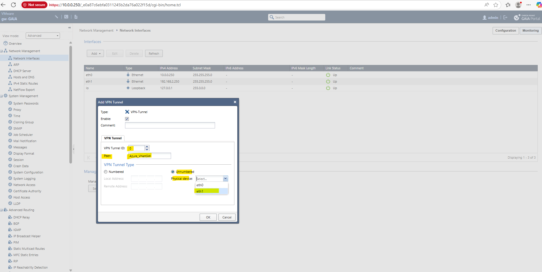
Under Network Management -> Network Interfaces click on Add -> VPN Tunnel.
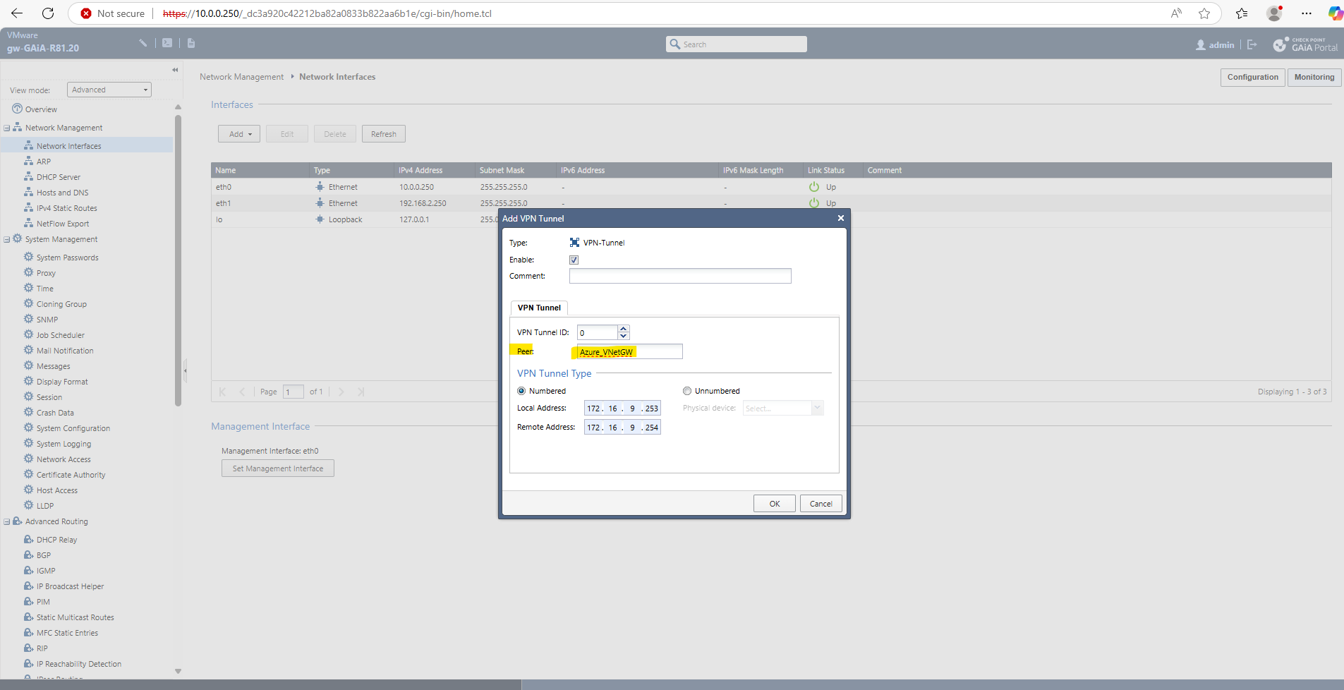
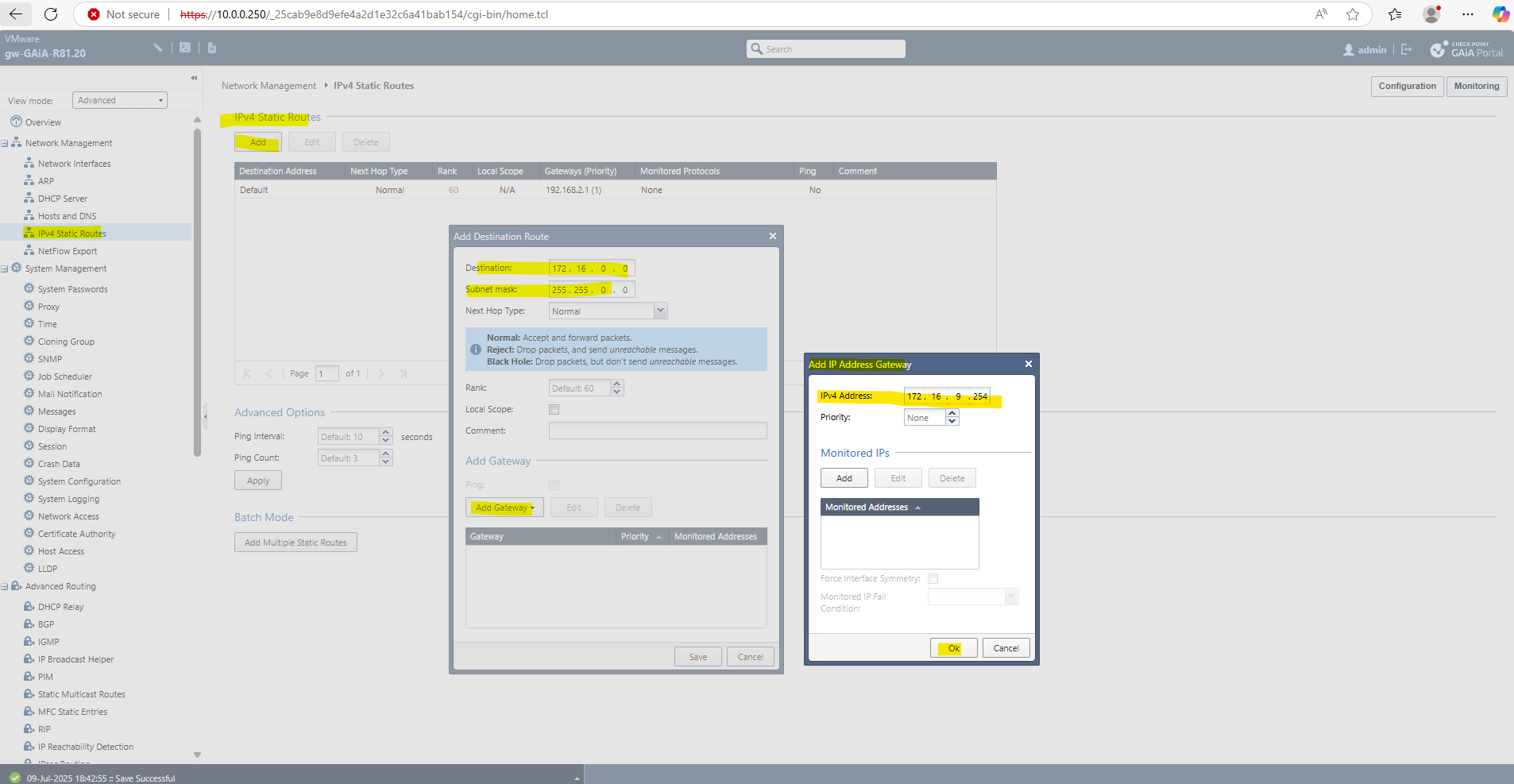
When connecting two Check Point gateways, the VPN Tunnel ID must be the same on both sites. Below I will configure a numbered VTI interface where I will assign the counterpart IP address or left IP address of Azure’s BGP peer IP address 172.16.9.254/32, allocated and assigned from Azure’s VPN Gateway Subnet, even BGP is not enabled and used here as shown below.
We can also use below for the VPN Tunnel Type here Unnumbered, for route-based VPNs with static routes we finally doesn’t need any IP addresses to be assigned on the tunnel interfaces, more about you will find in my following post when using Juniper as VPN device.
About how to configure an unnumbered tunnel interface here and adding a static route for you will find further down.
VPN Tunnel ID: A number that gets added to the VTI interface called vpnt*, where the asterisk is the VPN tunnel ID number specified . For VPN tunnel ID = 1, the interface is labeled vpnt1. When connecting two Check Point gateways, this ID must be the same on both gateway, in case of Azure as 3rd party peer this ID doesn’t matter and is not used.
Peer: The name of the interoperable device (the remote peer ==> our Azure virtual network gateway) that we created earlier for the IPSec tunnel. In my case, this name here is Azure_VNET_Gateway.
!!! Note !!!
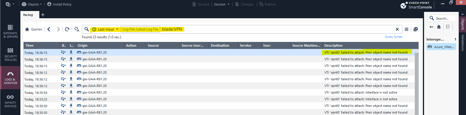
This remote peer name must match the name of the interoperable device we created for the Azure gateway, otherwise the VTI cannot be attached to the tunnel and therefore the tunnel doesn’t came up. See the screenshot below.
In case the peer name of the VTI above as mentioned doesn’t match the name of the interoperable device we created for the Azure gateway, the tunnel doesn’t came up and you will see the following entries in the logs filtered for blade:VPN.
VTI ‘vpnt0’ failed to attach: Peer object name not found
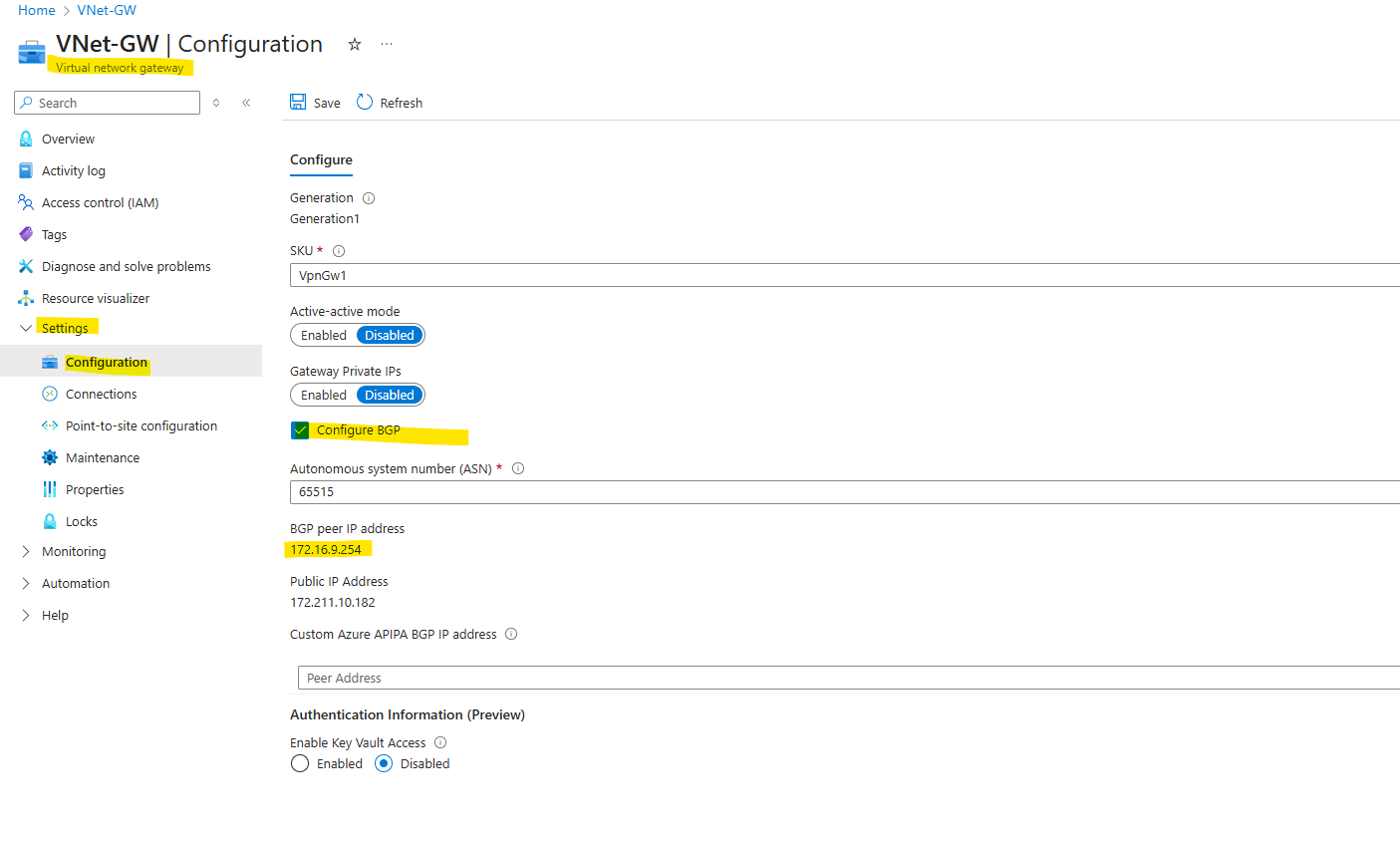
To determine these local addresses for the VTI interfaces, in Azure on the virtual network gateway blade under settings -> configuration check the Configure BGP checkbox just temporarily to see the local IP address which Azure is using as VTI interface IP address. This is the BGP peer IP address finally. And because this is a /30 subnet, our on-premise site needs to use 172.16.9.253 for the VTI interface.
The next hop for the static route from on-premise to the Azure VNet 172.16.0.0/16 we need to set then to this BGP peer IP address 172.16.9.254.
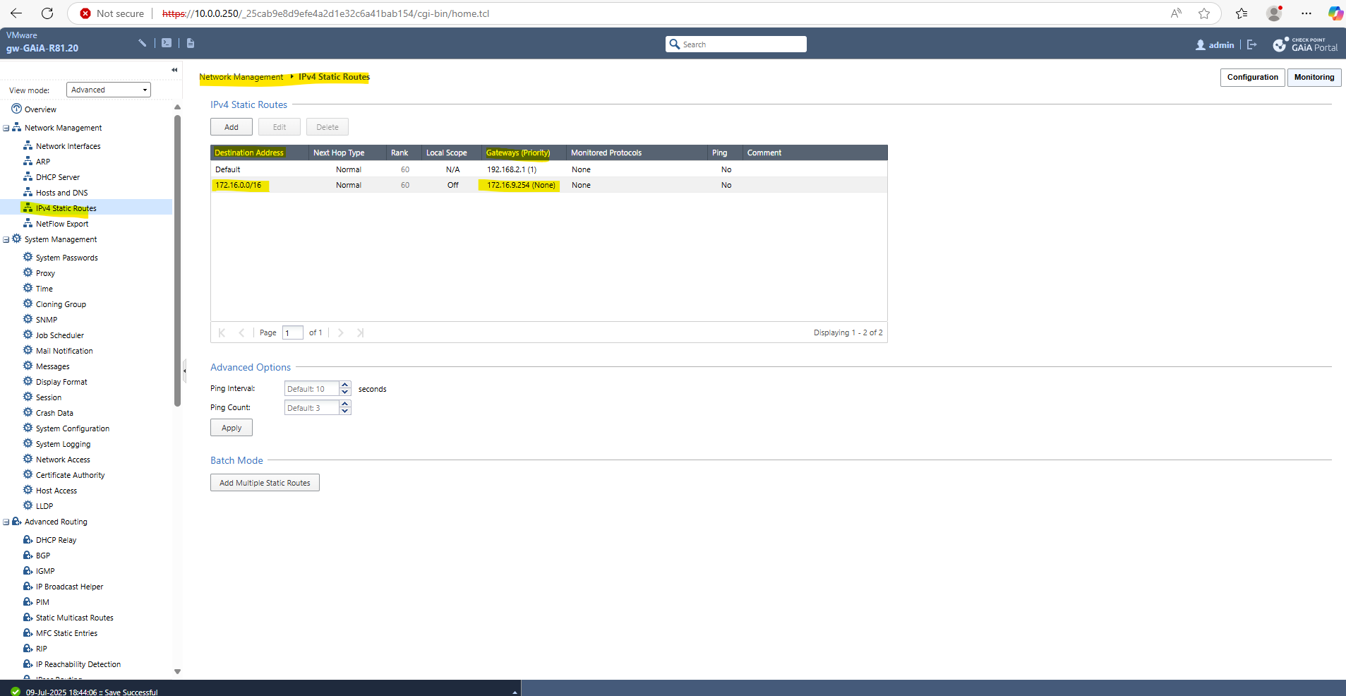
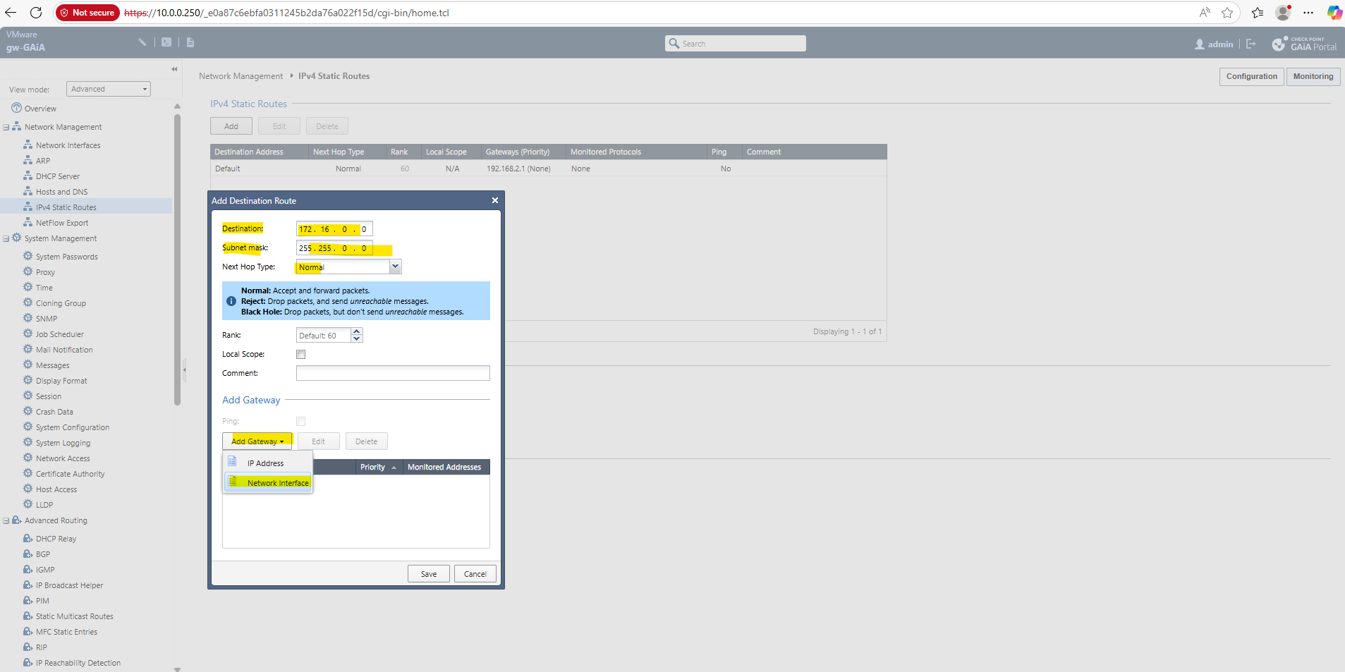
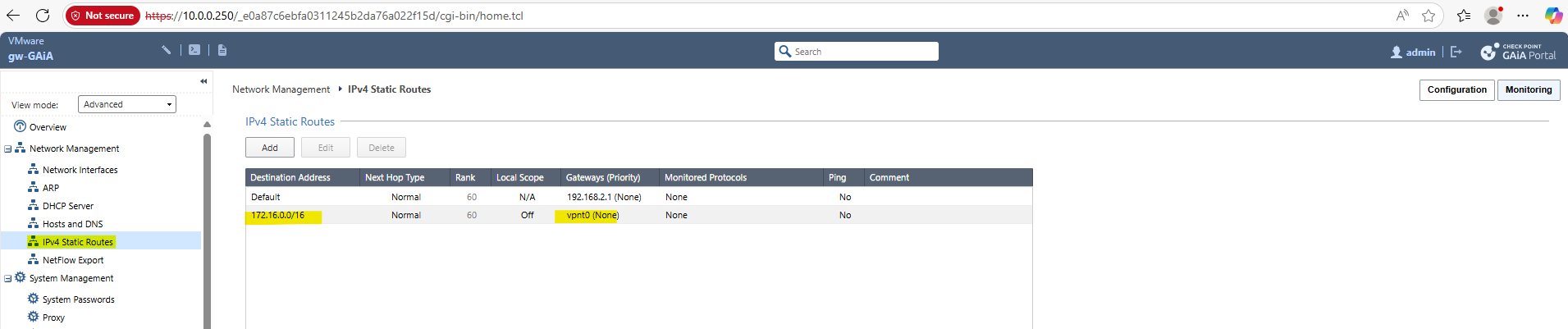
We now create the static route to the Azure VNet 172.16.0.0/16 on Check Point. Because it’s the only route to this network we don’t need to specify a priority.
Under IPv4 Static Routes click on Add.
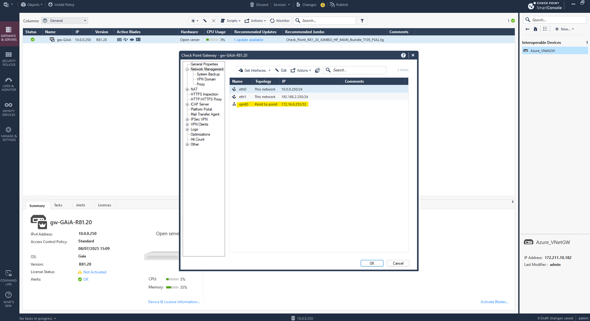
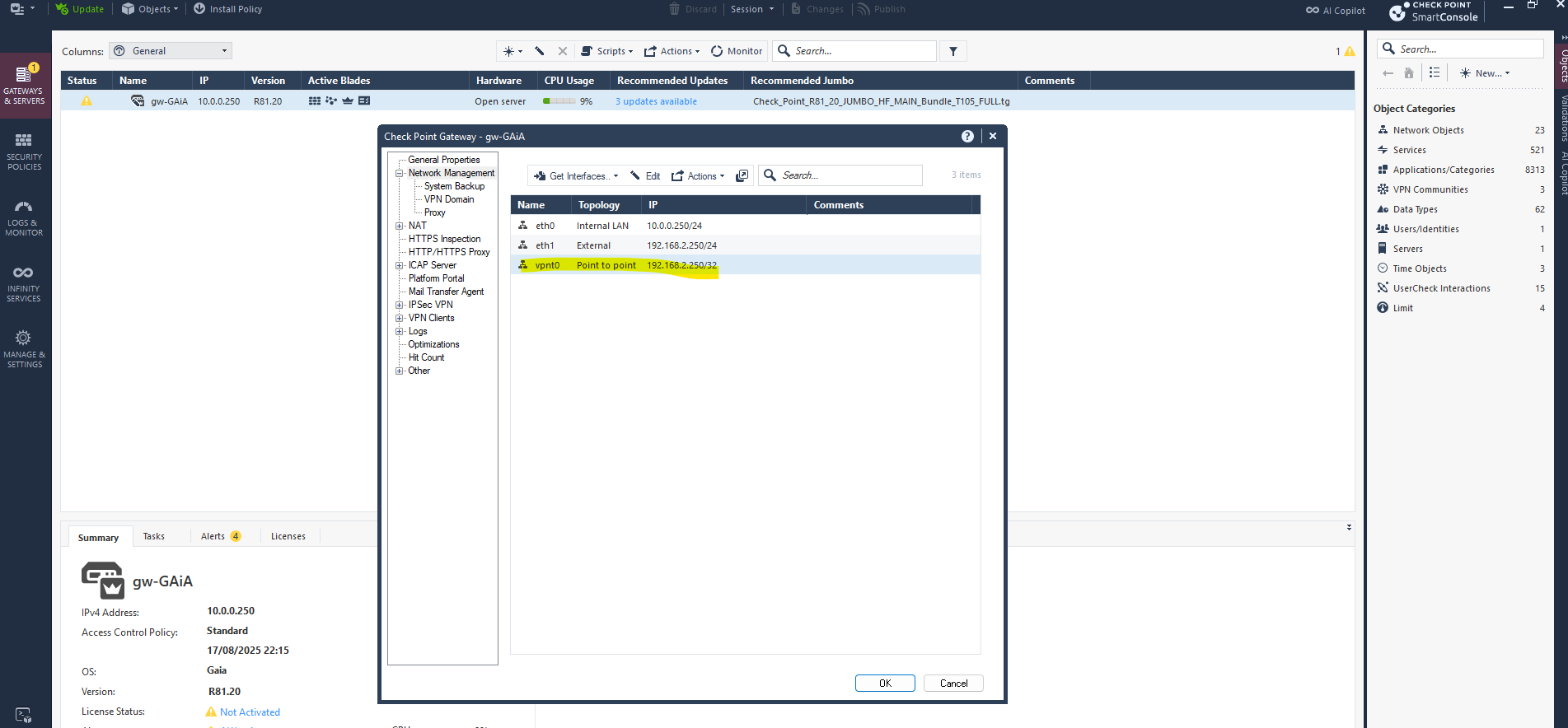
We can now go back to the SmartConsole under Gateways & Servers to get and publish the new VTI interface.
Click on Get interfaces and accept them.
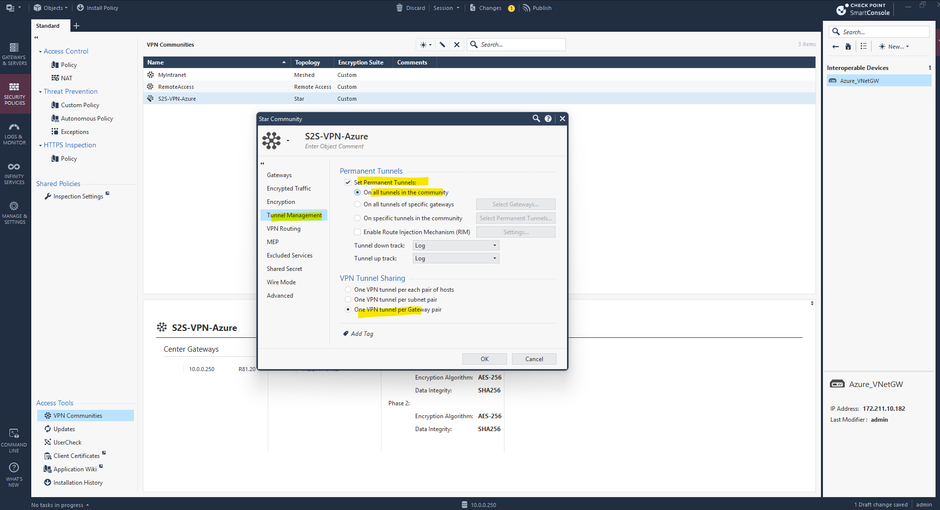
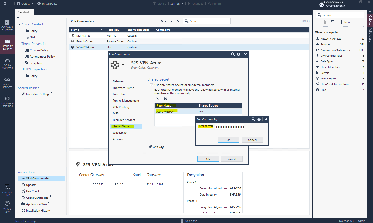
We can now finish the VPN Community and move on with the Tunnel Management section, click on Tunnel Management within the VPN community.
Here check Set Permanent Tunnels and select On all tunnels in the community, for the VPN Tunnel Sharing settings select One VPN tunnel per Gateway Pair when configuring a route based VPN tunnel.
We also need to set the shared secret which of course must match with the Azure shared secret.
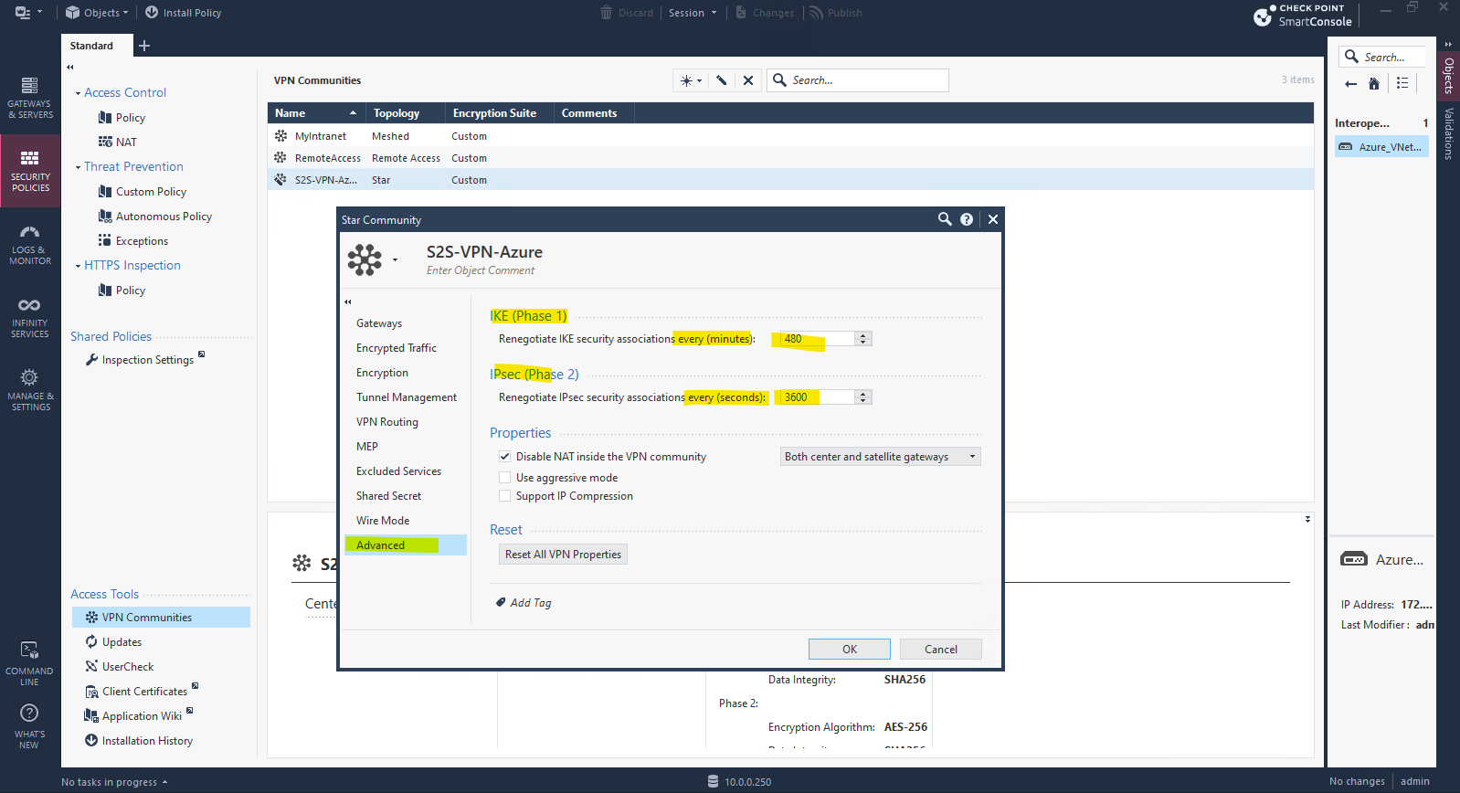
Finally under Advanced also set the phase 1 and phase 2 renegotiation interval which also must match with the Azure site.
!!! Note !!!
Here in Check Point the interval for phase 1 is set in minutes instead seconds as on most other VPN devices. So 480 minutes for phase 1 finally is equal to the 28800 seconds set in Azure.
From now on the VPN tunnel should be up and working.
Besides just triggering traffic through the tunnel to see if it works we can also check if the tunnel is up by using the GAiA CLI.
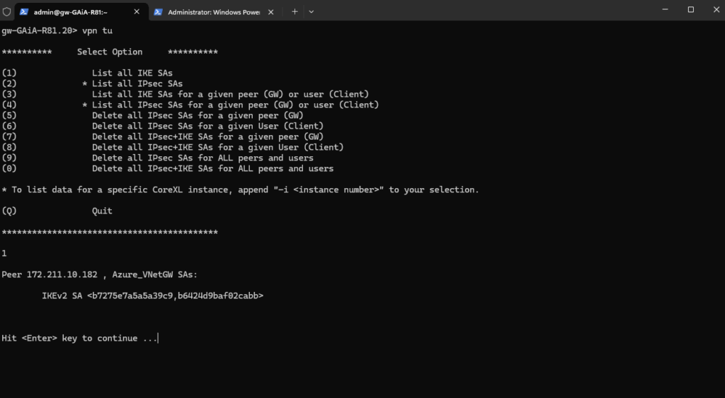
Login and run the following command to first check if phase 1 is up.
gw-GAiA-R81.20> vpn tu
To see the phase 1 tunnel enter (1). You then should see the peer information below.
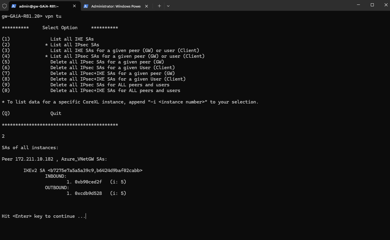
Then next to check if also the phase 2 tunnel is up.
gw-GAiA-R81.20> vpn tu
To see the phase 2 tunnel enter (2). You then should see the following peer information below.
Further under Logs & Monitor and filtered for the blade:VPN you should see the following log entry with Key Install under Action. (Source the Check Point gateway and Destination the public IP address of the Azure virtual network gateway)
This indicates that the Check Point gateway successfully completed phase 2 of the IPSec VPN negotiation and installed the new IPSec keys (SAs) for the tunnel.
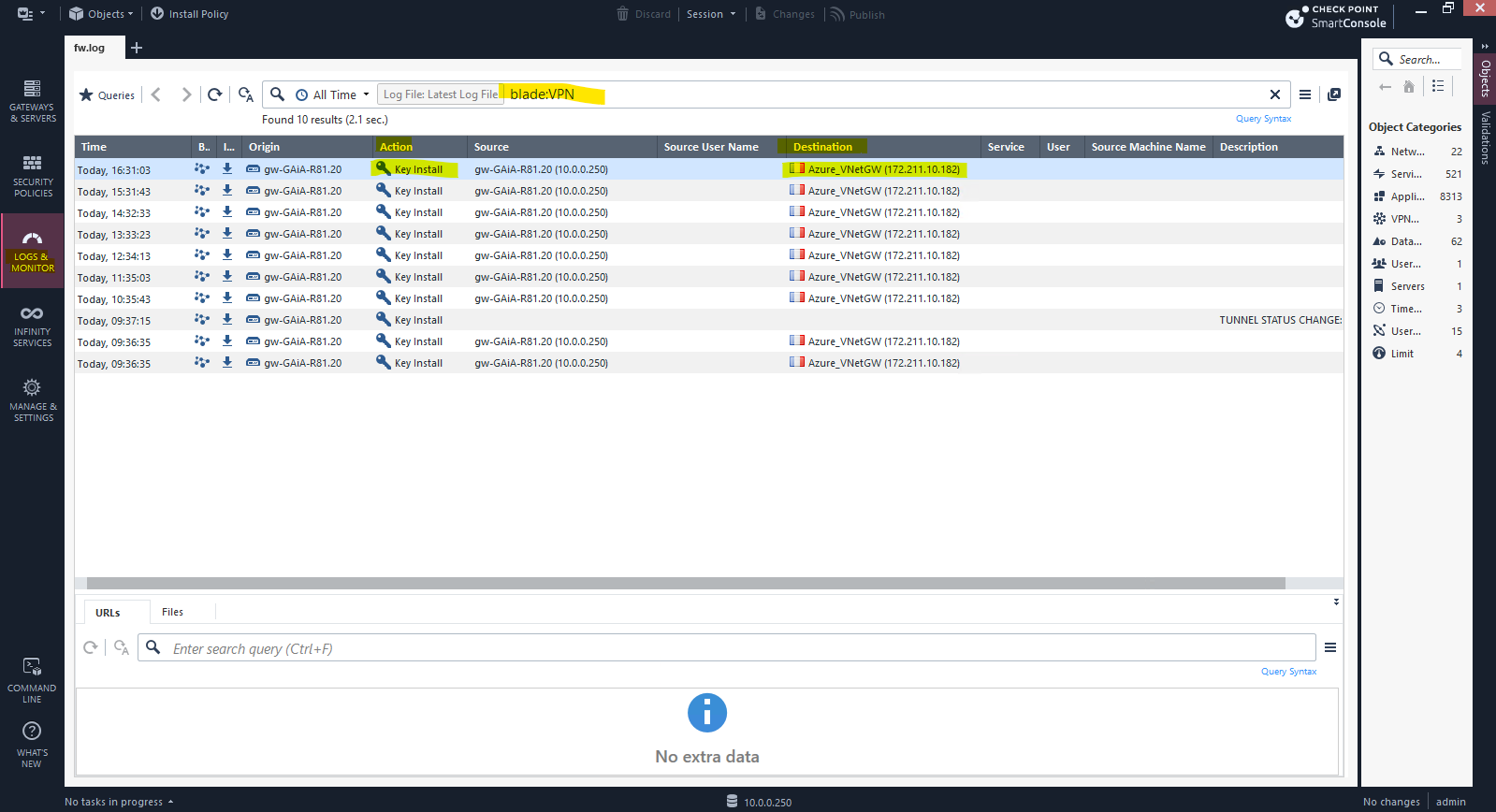
Further we can see above, that the phase 2 IPSec tunnel is re-negotiated and established each hour which is finally the interval we set previously on the VPN Community under Advanced as shown below.
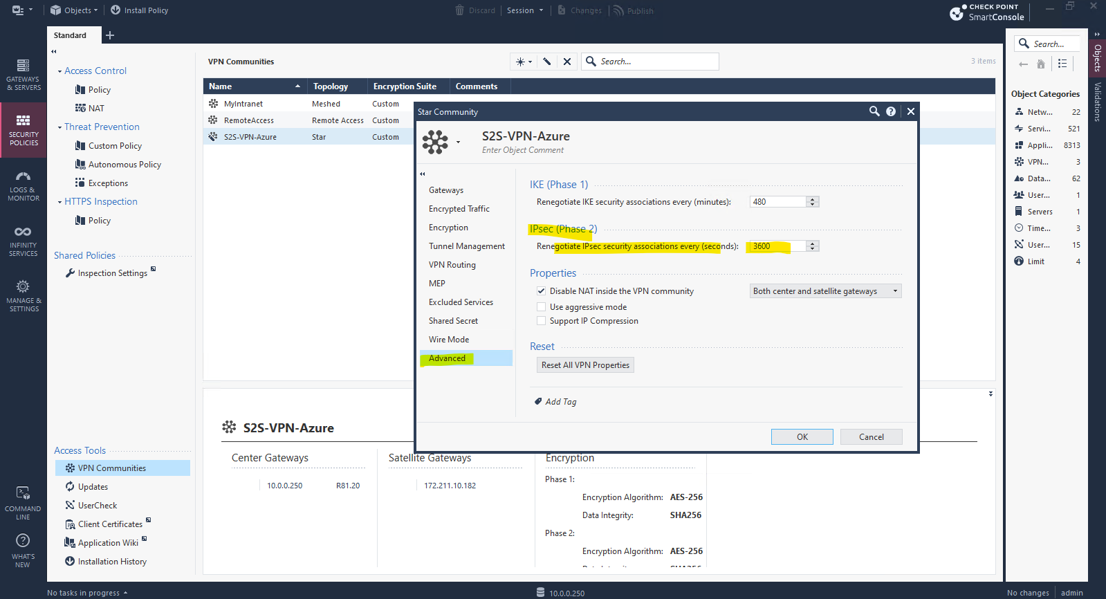
In Azure we set the phase 2 IPSec IPsec SA lifetime directly on the connection.
IKE Main Mode SA lifetime (phase 1) is fixed at 28,800 seconds on the Azure VPN gateways.
Using for the VPN Tunnel Type Unnumbered
To use unnumbered virtual tunnel interfaces as already mentioned above, we need to select below Unnumbered and the external interface of GAiA, in my case eth1.
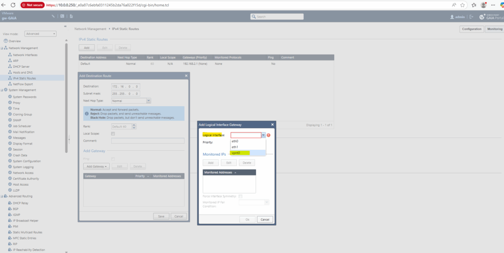
Under Add Gateway, this time select Network Interface as we used an unnumbered tunnel interface.
Select for the logical interface our newly created tunnel interface named vpnt0, click on OK and Save.
We can now go back to the SmartConsole under Gateways & Servers to get and publish the new VTI interface.
Click on Get interfaces and accept them.
With an unnumbered VTI, the tunnel itself doesn’t have its own IP address. Instead, it uses the IP address of an existing physical interface on the firewall as its source for routing and tunnel traffic, here the IP address of GAiA’s external interface with the IP 192.168.2.250.
In a route-based IPsec VPN, our traffic is selected by routes via the VTI interface bound to our IPsec Security Association (SA).
The SA already defines the secure “pipe” between the two peers based on Phase 2 settings (SPI, encryption, authentication).
When we add the static route for the Azure virtual network and set as next hop this unnumbered interface, Check Point doesn’t send packets to an IP, it sends them to the interface.
The forwarding engine sees that interface is mapped to an active IPsec SA and encapsulates the packets directly into ESP for the remote peer.
As mentioned finally its the same as on Juniper and shown here.
Allow Traffic between Azure and Check Point (on-prem)
To allow or deny traffic between Azure and on-prem we also need to define a new policy as usual. We also first need to create a new network object which contains the address space or our virtual network in Azure.
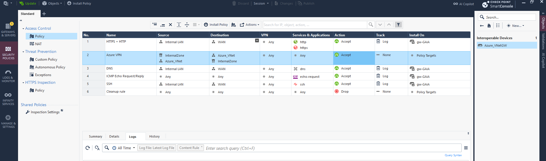
Enabling VPN Directional Match
Normally, VPN rules in the VPN column are bi-directional, meaning a rule applies for traffic in both directions.
Enabling VPN Directional Match in Check Point allows you to define the direction of VPN traffic in the firewall policy rules, such as:
- “From internal to remote peer”
- “From remote peer to internal”
- And more granular directional control across multiple VPN communities or gateways
This feature is especially useful when working with Star VPN communities, complex topologies, or overlapping encryption domains.
To enable directional match, select Menu > Global properties > VPN > Advanced, then click Enable VPN Directional Match in VPN Column.
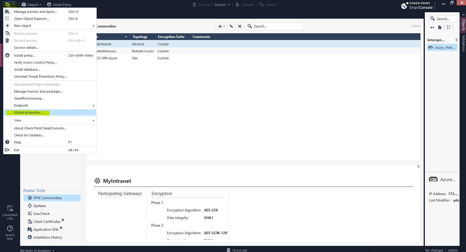
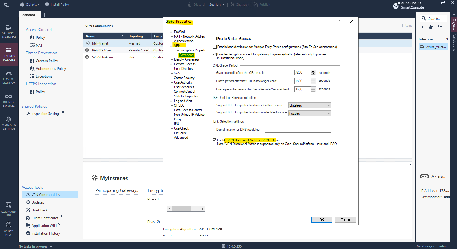
Without enabling VPN Directional Match on the Global properties this option is greyed out for the VPN column on the policy.
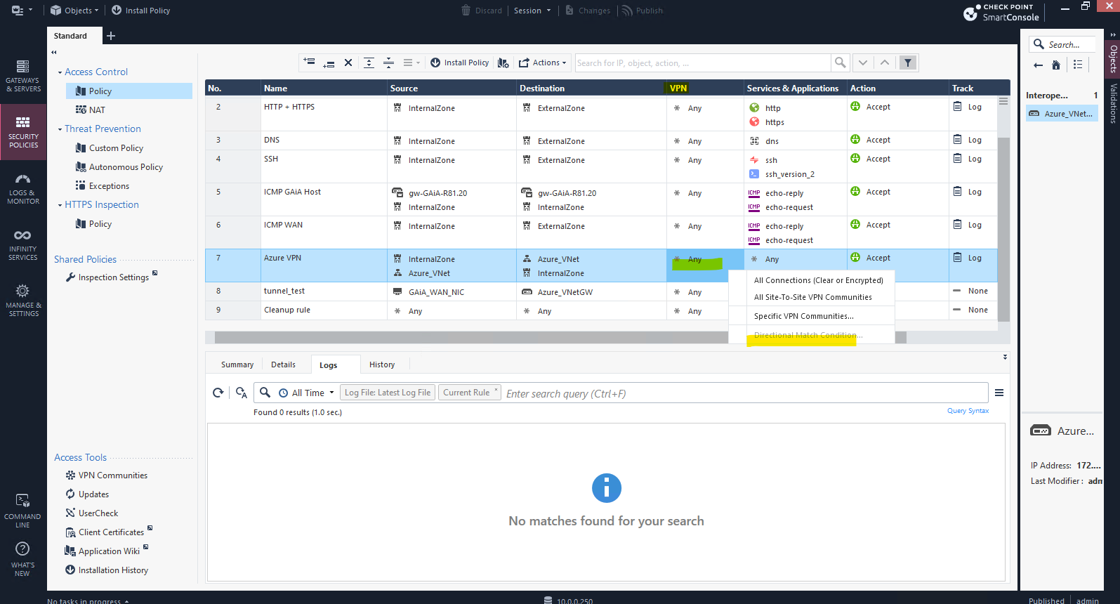
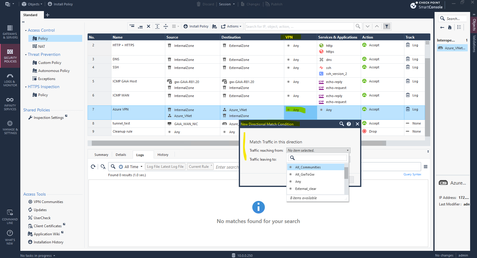
When enabled we can define these directions.
Restarting a VPN Tunnel via CLI
To restart a VPN tunnel on a Check Point gateway, you typically need to clear the existing Security Associations (SAs) for that tunnel. This forces the gateway to renegotiate Phase 1 (IKE) and Phase 2 (IPsec) with the remote peer.
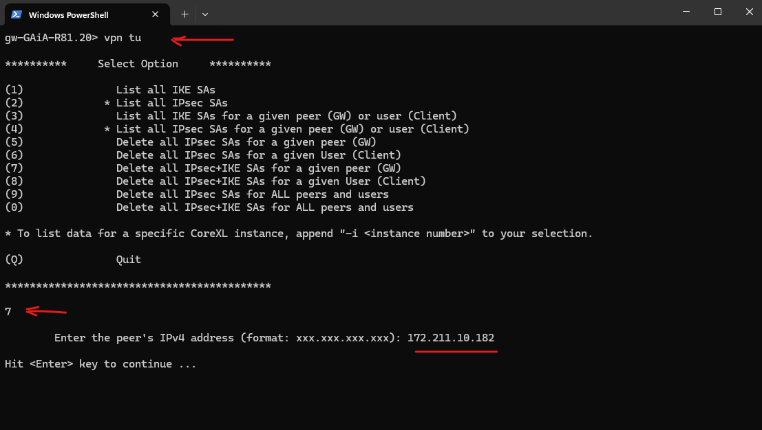
Type vpn tu in the CLI and press enter. Typically, you will choose option (7) Delete all IPsec+IKE SAs for a given peer (GW). The exact number might vary slightly depending on your Check Point version.
You will be prompted to enter the IP address of the remote VPN peer (gateway). Enter the public IP address of the Azure VPN Gateway (or the remote Check Point gateway).
gw-GAiA-R81.20> vpn tu

(7)               Delete all IPsec+IKE SAs for a given peer (GW)
The SAs for that tunnel will be cleared. The tunnel will attempt to re-establish immediately.
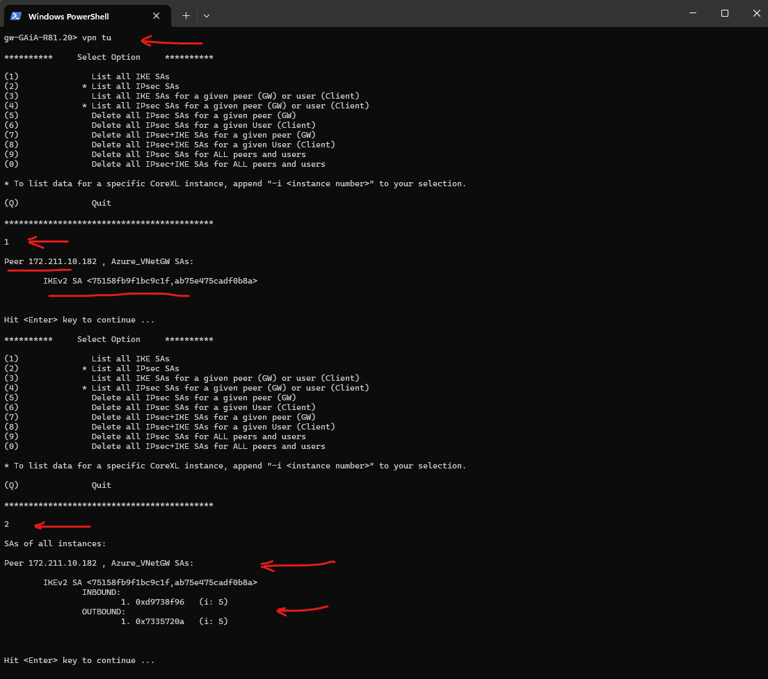
You can use vpn tu again and choose option (1) List all IKE SAs and (2) List all IPsec SAs to see if they have re-appeared.
Looks good.
Monitoring Tunnel Traffic by using the CLI
To monitor traffic live which is routed through the tunnel and its associated VTI’s, we can use the fw monitor command as shown below.
The fw monitor command in Check Point is a powerful packet capture tool that lets you trace traffic as it flows through the various inspection points inside the Check Point kernel.
Unlike tcpdump, which shows traffic at the interface level, fw monitor shows how Check Point processes the packets internally, including:
- Before inspection
- After policy enforcement
- Before and after encryption (for VPN)
- After routing
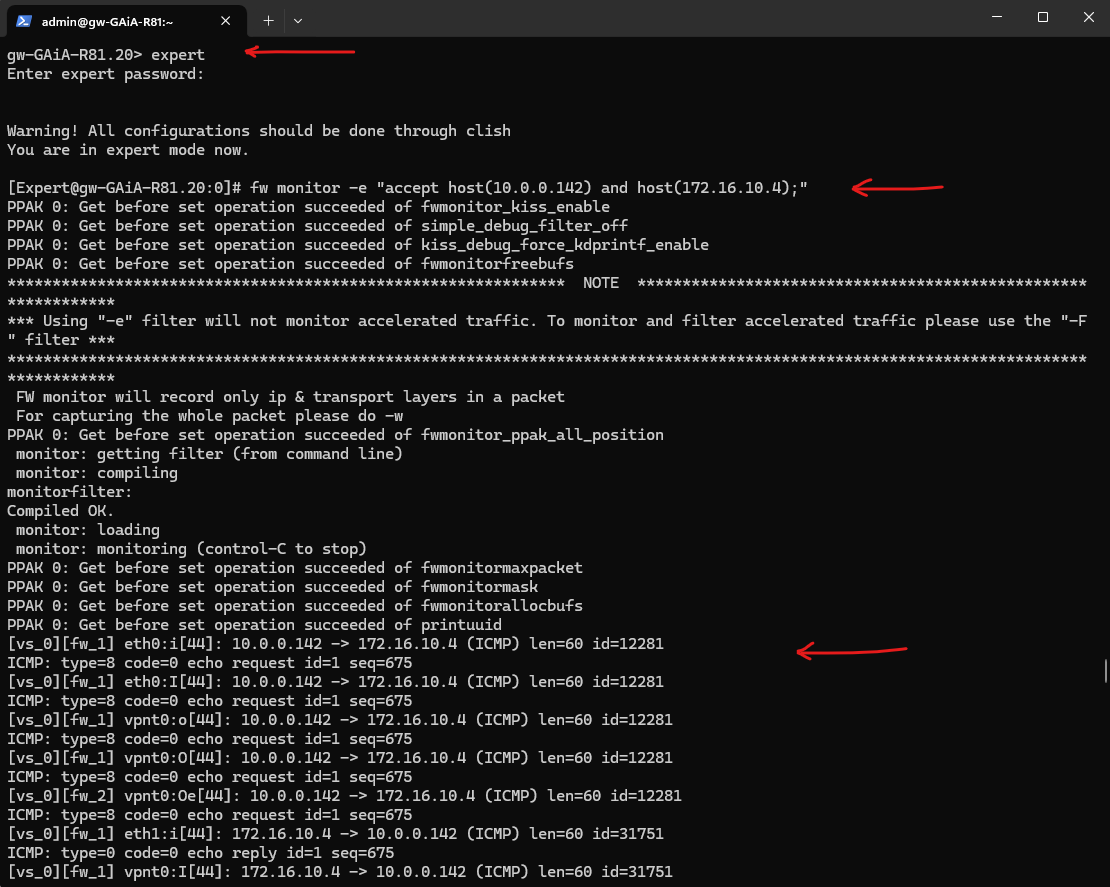
For example the following command will capture packets between the host 10.0.0.142 (on-premise VM) and host 172.16.10.4 (Azure VM) in my case.
I will ping (ICMP Echo Request messages) here the Azure VM from an on-premise VM.
gw-GAiA-R81.20> expert
[Expert@gw-GAiA-R81.20:0]# fw monitor -e "accept host(10.0.0.142) and host(172.16.10.4);"

or all ICMP traffic:
[Expert@gw-GAiA-R81.20:0]# fw monitor -e "accept icmp;"
Links
Getting Started with Site-to-Site VPN
https://sc1.checkpoint.com/documents/R81/WebAdminGuides/EN/CP_R81_SitetoSiteVPN_AdminGuide/Topics-VPNSG/Getting-Started.htmCheck Point: Route-Based
https://docs.oracle.com/en-us/iaas/Content/Network/Reference/checkpointCPEroutebased.htmHow to configure IPsec VPN between Check Point Security Gateways and Azure Virtual WAN VPN Gateway
https://support.checkpoint.com/results/sk/sk176249Overview of Route-based VPN
https://sc1.checkpoint.com/documents/R81/WebAdminGuides/EN/CP_R81_SitetoSiteVPN_AdminGuide/Topics-VPNSG/Route-Based-VPN.htm?tocpath=Route%20Based%20VPN%7C_____1#Overview_of_Route-based_VPNVPN Tunnel Interfaces
https://sc1.checkpoint.com/documents/R81/WebAdminGuides/EN/CP_R81_Gaia_AdminGuide/Topics-GAG/VPN-Tunnel-Interfaces.htmConfigure custom IPsec/IKE connection policies for S2S VPN and VNet-to-VNet: PowerShell
https://learn.microsoft.com/en-us/azure/vpn-gateway/vpn-gateway-ipsecikepolicy-rm-powershell