Cross-Hub Connectivity in Google Cloud using HA VPN and NGFW Appliances
In multi-hub Google Cloud environments, teams often need full connectivity between workloads that sit behind different Network Connectivity Center (NCC) hubs or even across projects.
In this post, we will see how to interconnect two hubs using HA VPN, Cloud Router (BGP control-plane), and optional a NGFW appliance (pfSense in my case) to route and inspect traffic between both sides, creating a resilient, fully dynamic cross-hub network fabric in GCP.
pfSense can effectively function as a Next-Generation Firewall, especially when extended with its rich ecosystem of security packages.
NGFW Appliance Term
A Next-Generation Firewall (NGFW) is a modern security appliance that goes beyond traditional port- and protocol-based filtering by providing deep packet inspection, application awareness, and user-level control.
Unlike classic firewalls that only decide based on source, destination, and port, an NGFW can identify and enforce policies on specific applications, users, and content, even when traffic uses common ports or encrypted protocols.
Most NGFWs integrate capabilities such as intrusion prevention (IPS), malware and threat detection, URL or DNS filtering, and advanced logging and analytics.
This makes them suitable not just for perimeter defense but also for segmentation, compliance, and secure hybrid-cloud connectivity in modern network environments.
pfSense and NGFW Capabilities
pfSense can effectively function as a Next-Generation Firewall, especially when extended with its rich ecosystem of security packages.
Out of the box, pfSense provides stateful packet inspection, VPN, routing, and user authentication, and when combined with add-ons such as Snort or Suricata for intrusion prevention and pfBlockerNG for threat intelligence and DNS filtering, it reaches full NGFW capability.
While commercial solutions like Palo Alto or Fortinet integrate these features more tightly, pfSense offers a flexible, modular, and cost-effective alternative for both enterprise labs and production environments.
Setting up HA VPN in both Hub VPCs
To establish secure and dynamic connectivity between both hub networks, we’ll start by creating HA VPN gateways and Cloud Routers in each Hub VPC.
Further down we will also see how to connect two hub networks by using NGFW appliances (pfSense) instead HA VPN to establish a site-to-site VPN tunnel between both.
This setup forms the foundation for our inter-hub link providing redundant tunnels and automatic route exchange via BGP.
About how to set up HA VPN you can read my following posts. In both posts I will set up HA VPN between GCP and my on-prem vSphere lab environment, but the steps are nearly the same.
The only steps they will differ when connecting two cloud peers instead are shown below.
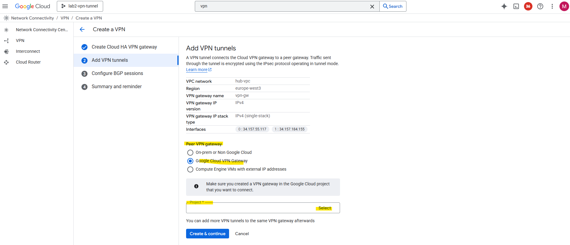
When connecting both GCP NCC Hubs, we need to select for peer VPN gateway here Google Cloud VPN Gateway instead On-prem or Non Google Cloud when adding the tunnel.
When selecting below Google Cloud VPN Gateway, we also need to select the project where the NCC Hub and HA VPN which we want to connect to resides.
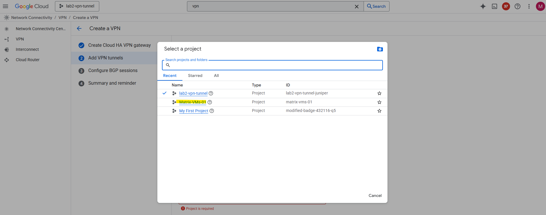
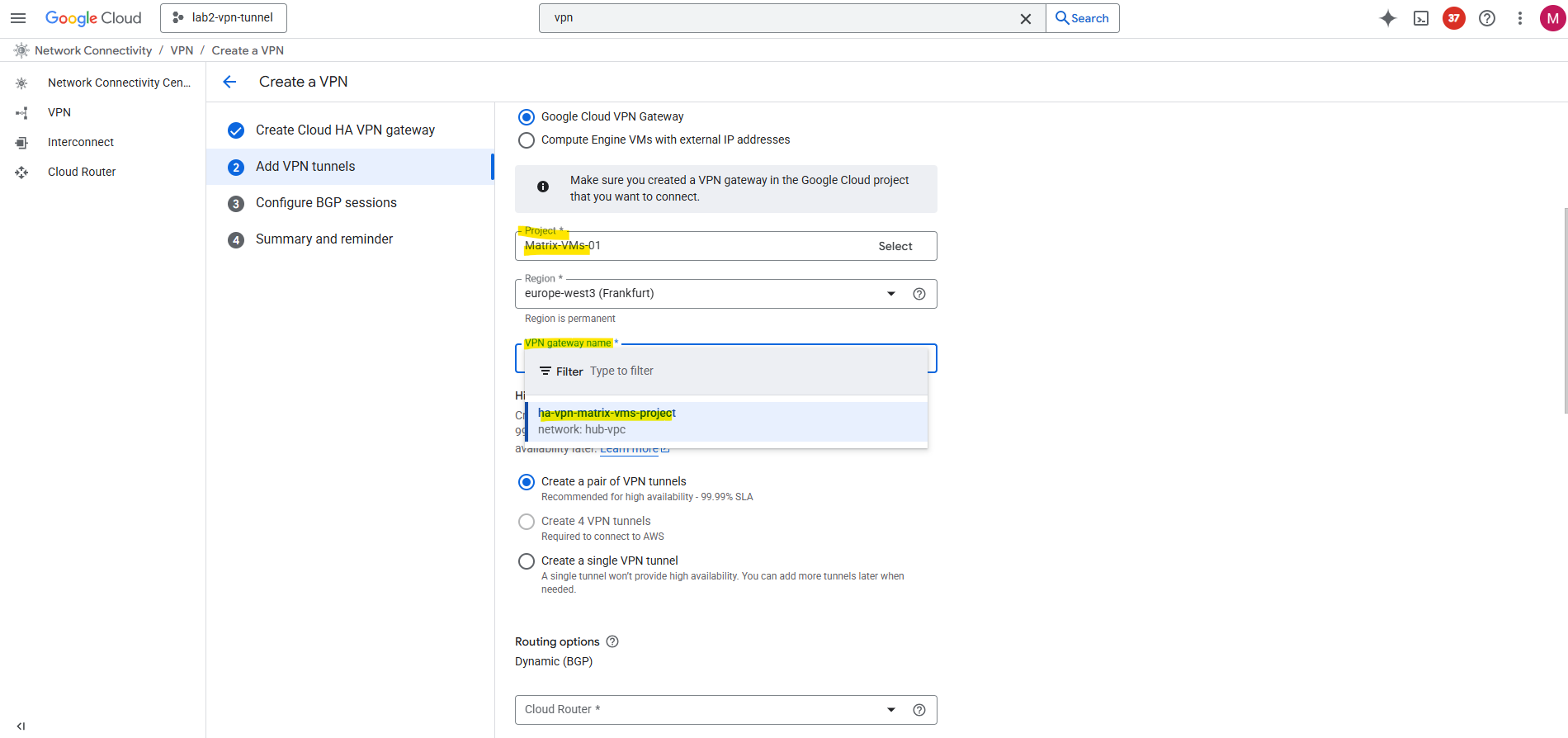
In my case I wanted to connect the NCC Hub from my project named lab2-vpn-tunnel with my NCC Hub in project Matrix-VMs-01, therefore for the peer project I need to select below Matrix-VMs-01.
Then I can select the VPN gateway I created in this project in parallel to be available to each other on both sides during setup.
The other steps are finally the same as when setting up HA VPN with an on-prem peer.
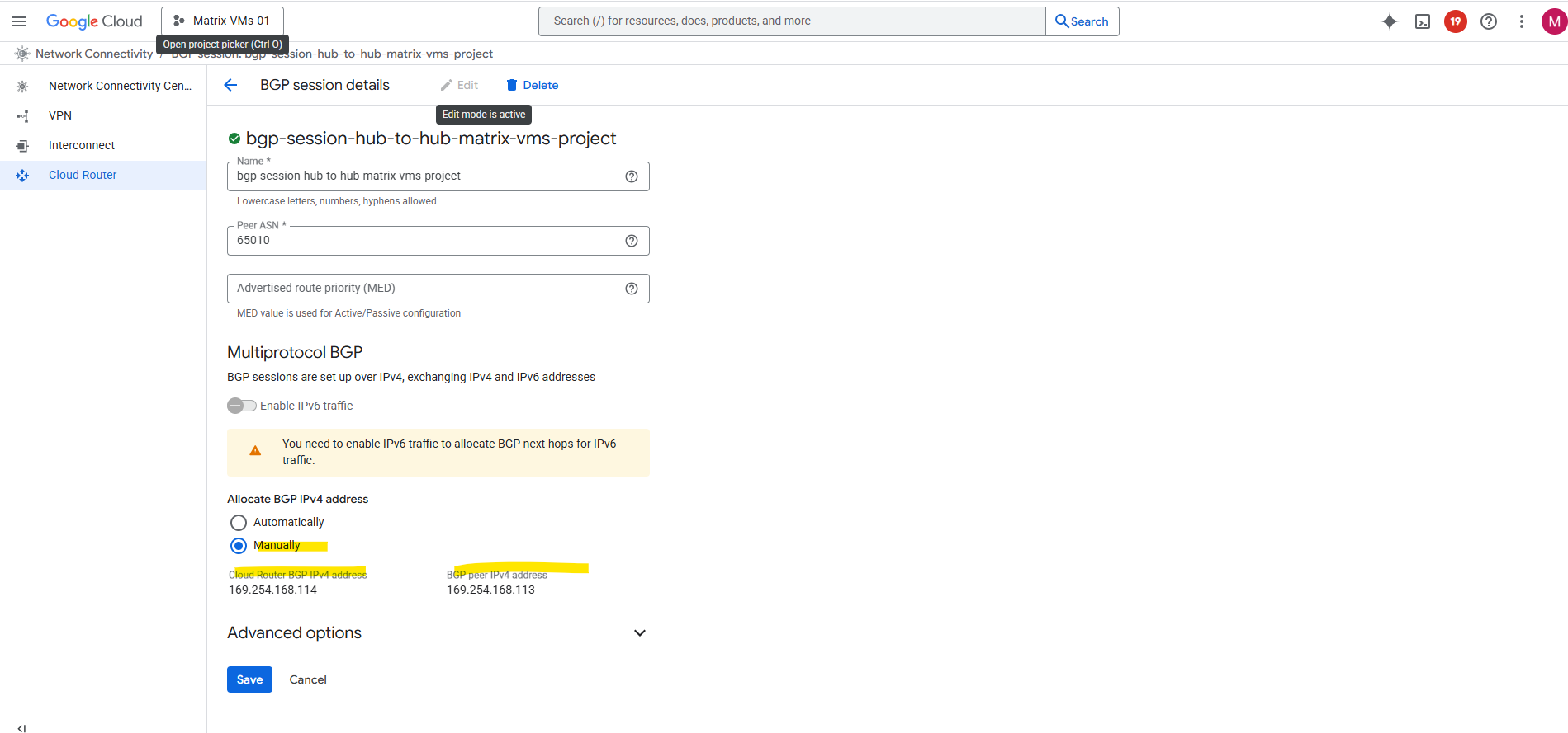
When creating the BGP session, I was using for the first side to allocate BGP IPv4 addresses automatically. We can then later assign them for the peer manually to fit in both sides, finally both sides must reside in the same /30 subnet.
Finally both tunnels are up and running.
In my project lab2-vpn-tunnel, the first tunnel below is from my post about building a centralized egress and hybrid connectivity hub and connecting my on-prem vSphere lab environment, shown here.
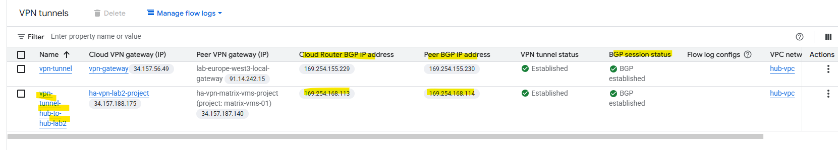
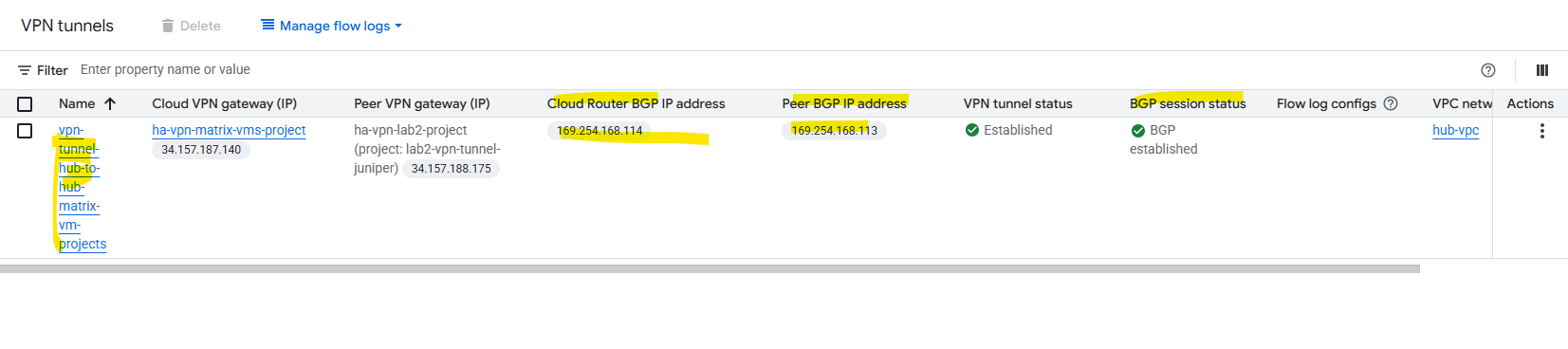
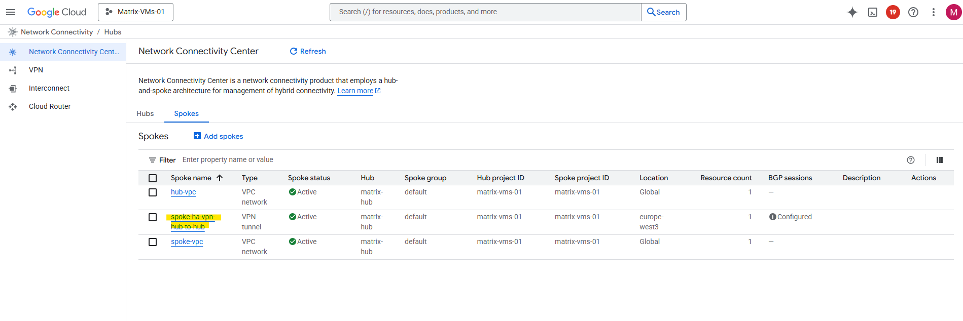
On the connected project Matrix-VMs-01.
Attach each HA VPN as a Hybrid Spoke to its Hub
With both HA VPNs and BGP sessions up, the next step is to bring them under the Network Connectivity Center.
By attaching each HA VPN and its Cloud Router as a hybrid spoke, we allow NCC to automatically exchange routes between the hubs and their connected VPC spokes.
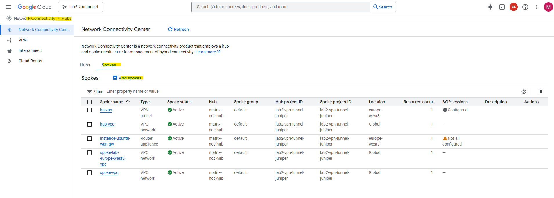
So in both NCC hubs browse to the Spokes tab and add a new spoke.
For the spoke type select VPN tunnel.
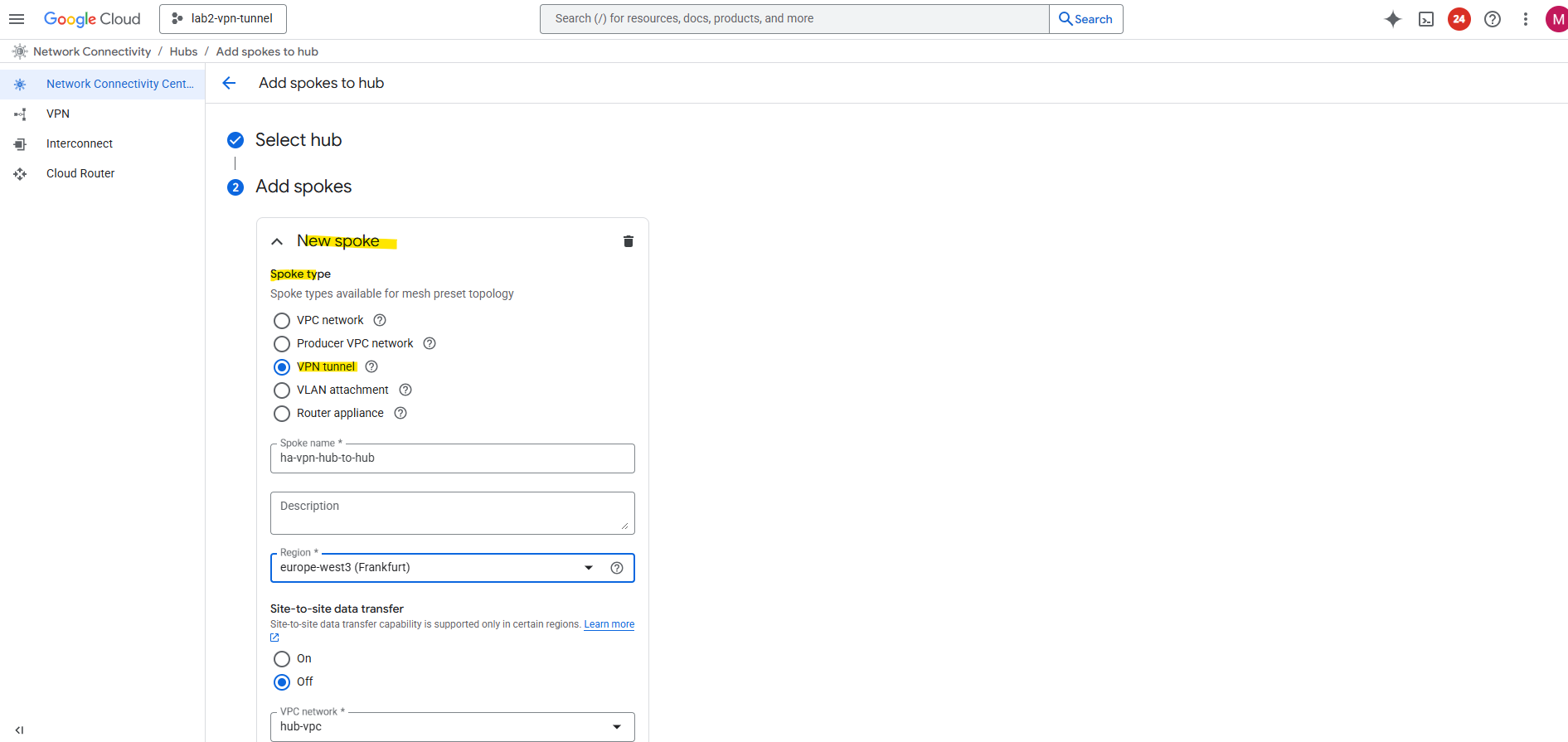
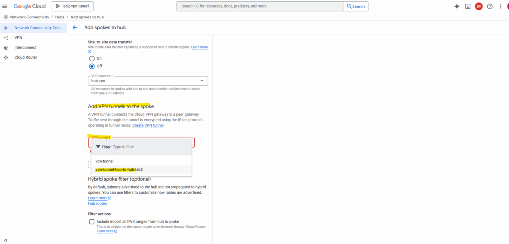
Select the hub-vpc where we deployed our HA VPN and click on Add tunnel.
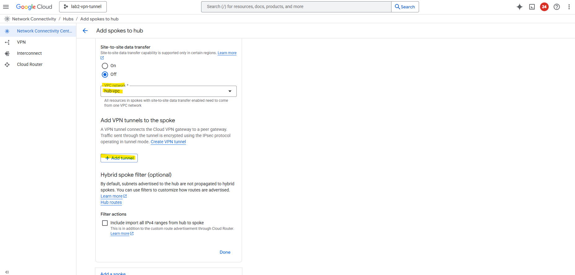
Select our previously created VPN tunnel and Create.
The first connects my on-prem vSphere lab environment as mentioned and shown here.
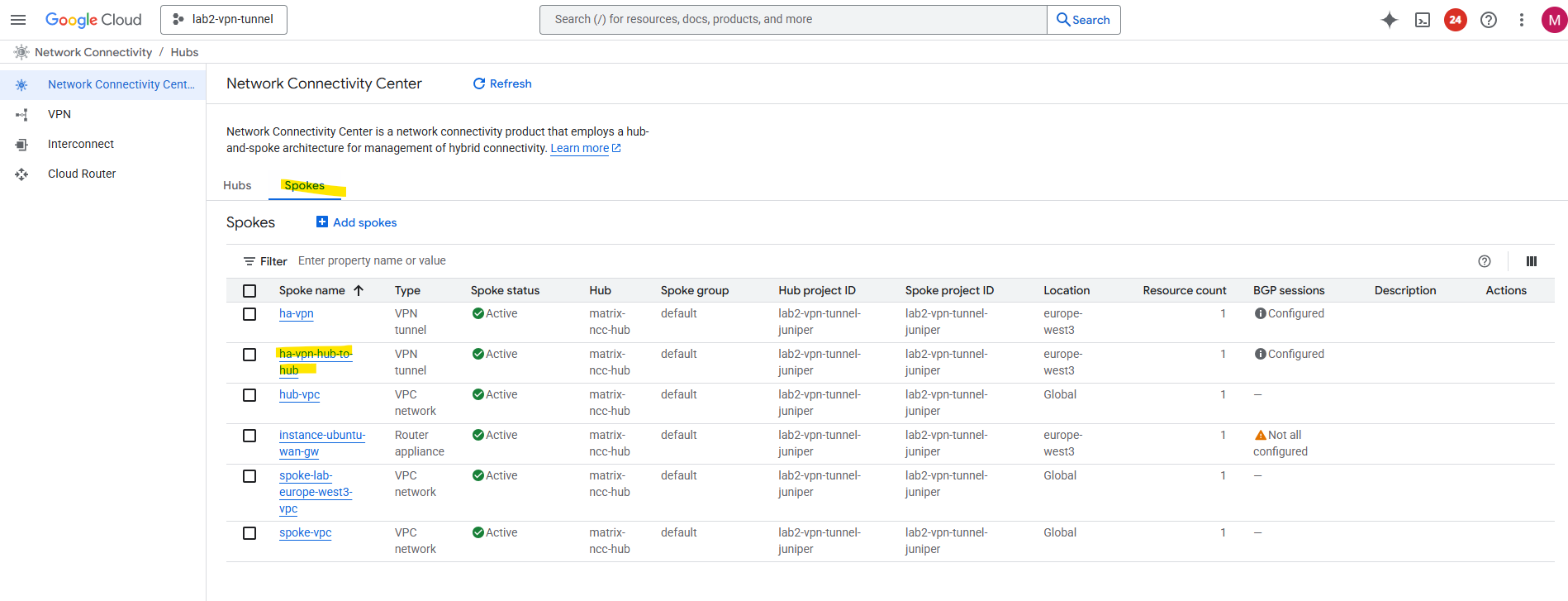
We also need to configure the same for our other NCC hub we connected to, I will skip the individual steps here, since they’re the same as before.
As both NCC hubs are now connected to each other, next we will first verify if already all routes are exchanged successfully between both sides (peers).
NCC will start exchanging these routes automatically between both hubs and their VPC spokes.
Verify Route Exchange in NCC
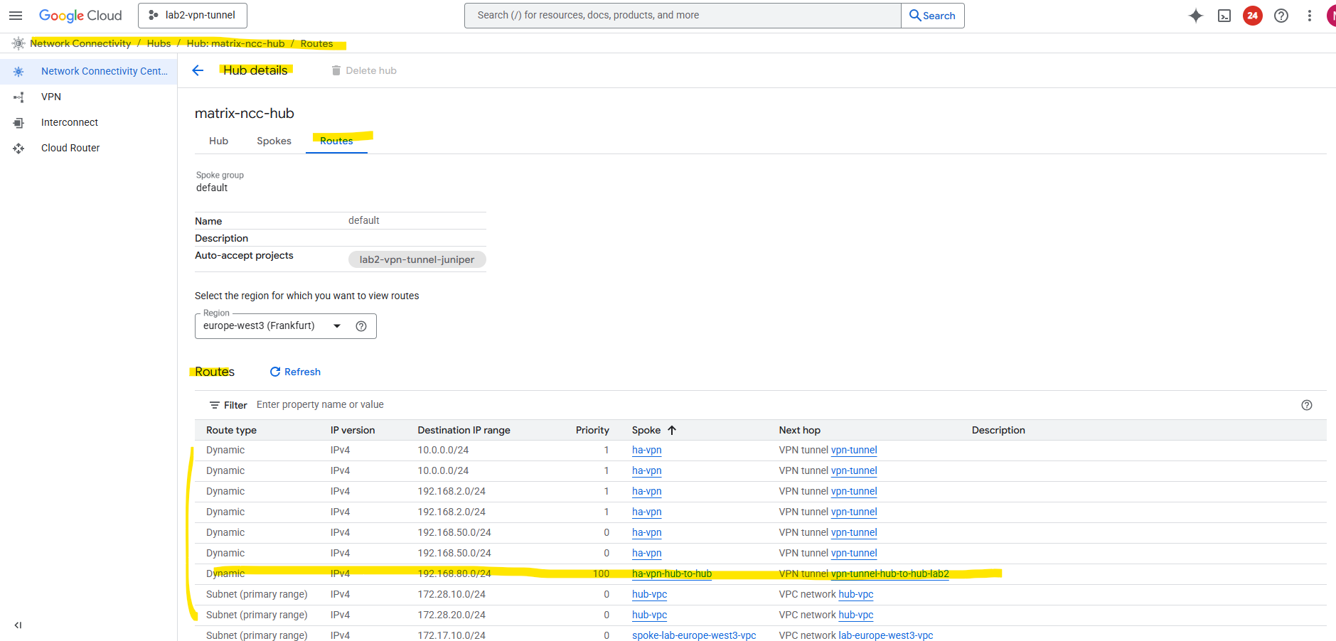
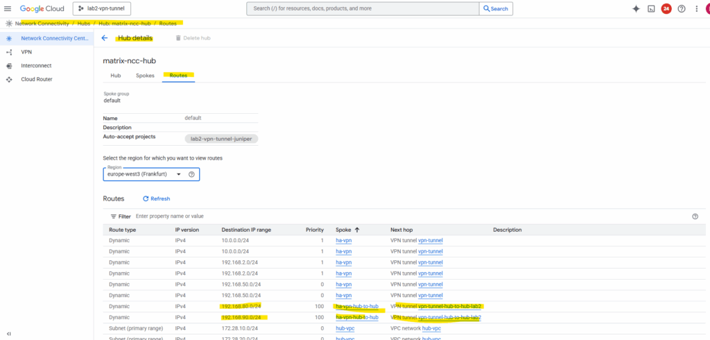
In each project (NCC hub) go to Network Connectivity Center → Hubs → (Your Hub) → Routes tab
On my project lab2-vpn-tunnel I had a bunch of routes because it contains two VPN tunnel spokes and acts as a Centralized Egress and Hybrid Connectivity Hub shown here.
The routes we are now interested in, are the ones for the VPCs (subnets) in our connected NCC hub in project Matrix-VMs-01.
So far just the subnet of the hub-vpc in project Matrix-VMs-01 are shown up and highlighted below (subnet 192.168.80.0/24).
The subnet in the spoke VPC in this project with 192.168.90.0/24 so far is not shown.
By default, when you create a Cloud Router for an HA VPN connection, it will only advertise the primary (hub) VPC network prefixes, that is, the subnets directly attached to the VPC where the Cloud Router lives.
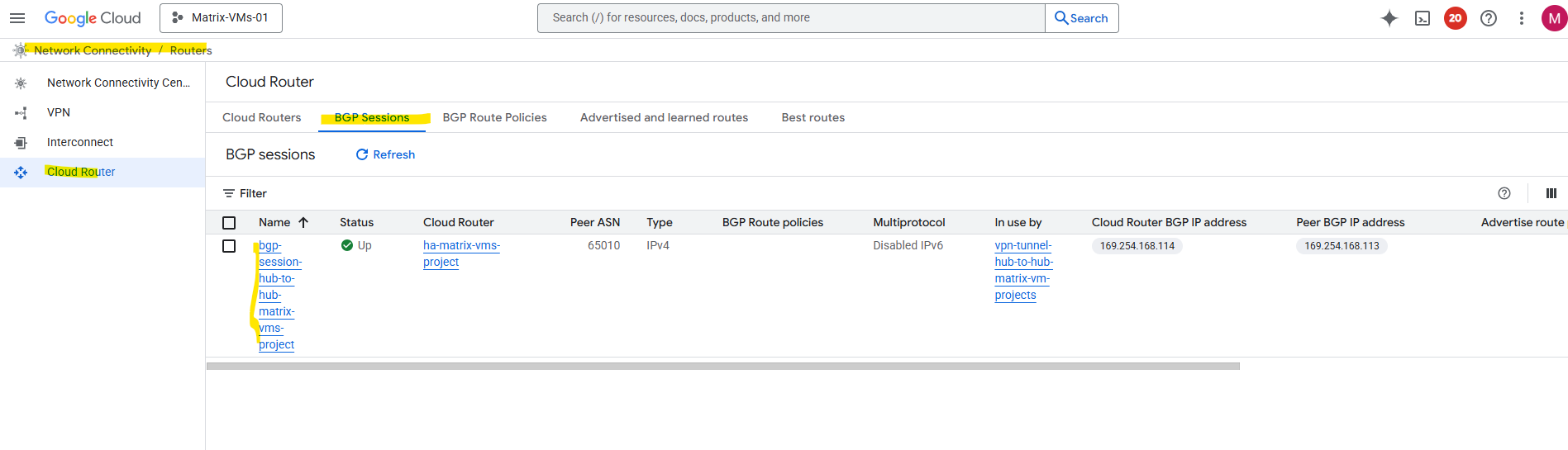
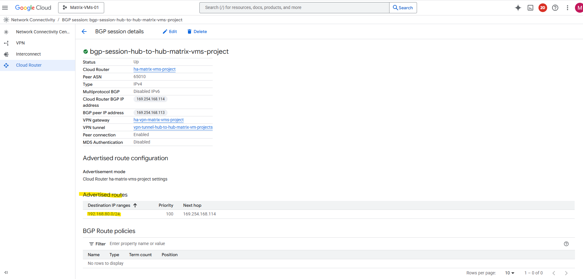
Navigate to the Cloud Router -> BGP Session tab within the Network Connectivity Center on both sides. Click on the BGP session.
Below we can already see, that so far just the 192.168.80.0/24 subnet is advertised from the NCC hub in project Matrix-VMs-01 as noticed previously above on the other side.
Click on Edit.
By default, it only advertises subnets from its own VPC. To include spoke routes, select Create custom routes below.
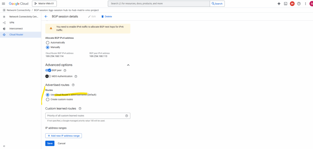
I will check Advertise all subnets visible to the Cloud Router and adding my so far not advertised workload subnet (192.168.90.0/24) which is associated with the spoke.
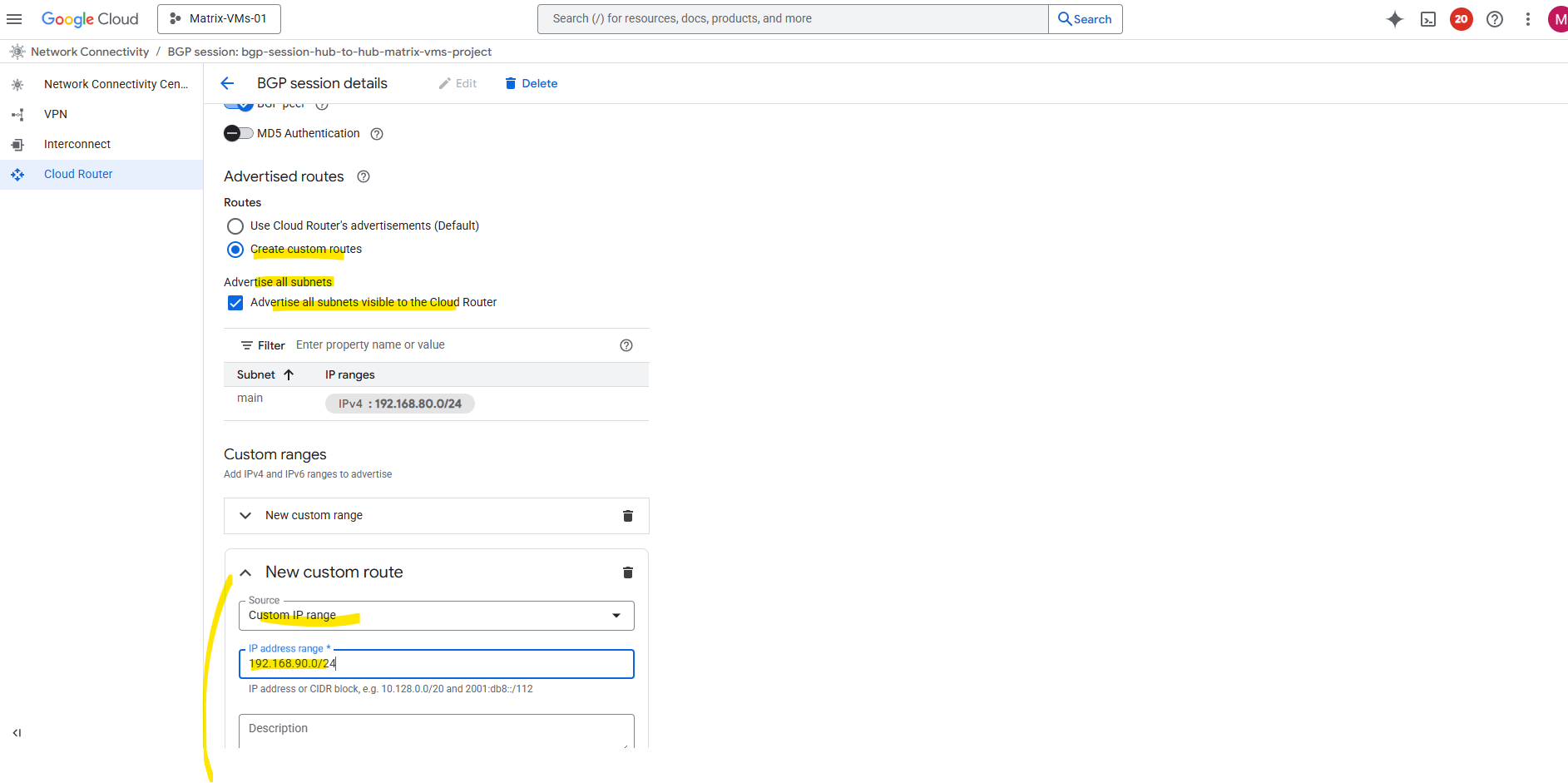
Now both subnets should be advertised to the peer (my lab2-vpn-tunnel projects NCC hub).
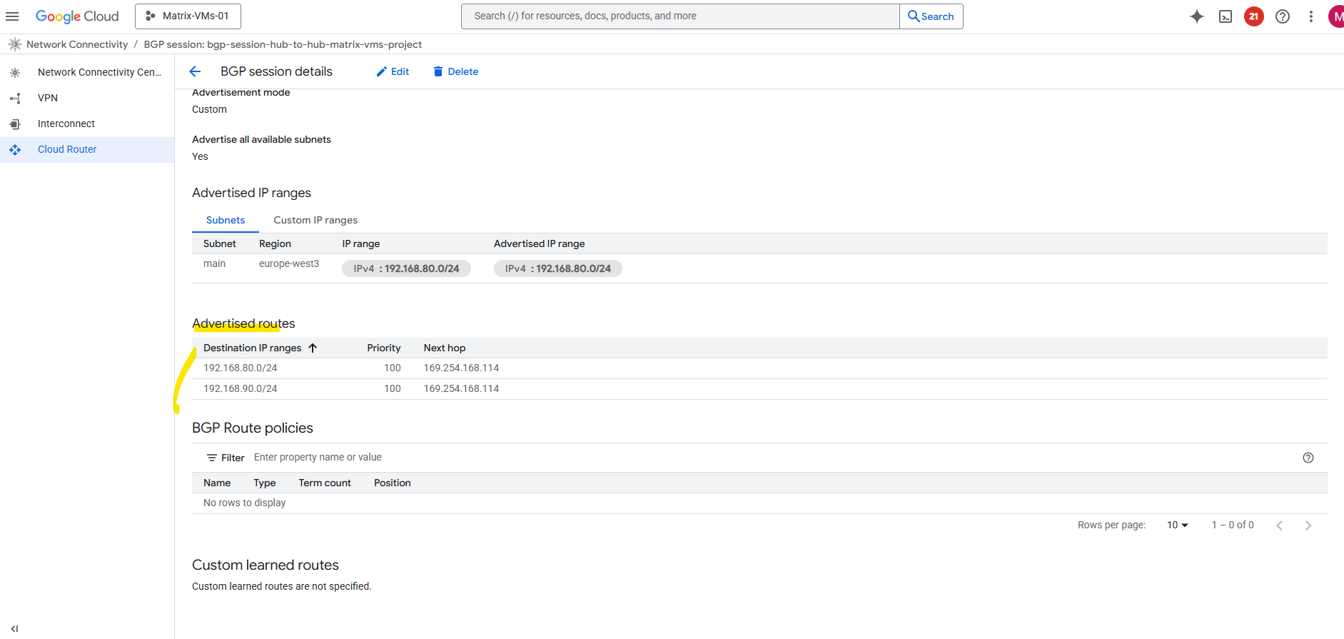
Looks good and the NCC hub in project lab2-vpn-tunnel already sees the new route from the spoke VPC in project Matrix-VMs-01.
The same we also need to configure on the other side resp. adding all spoke VPC subnets we want to be reachable by the other site.
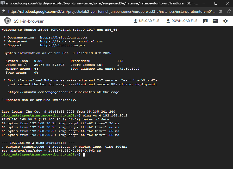
I will now perform a quick check to see if I can already send traffic from a workload (VM instance) running in the spoke VPC in project lab2-vpn-tunnel to a workload (VM instance) running in the spoke VPC in project Matrix-VMs-01.
I will just send ICMP Echo Request messages to the destination VM, inbound/ingress ICMP traffic is already allowed and configured by a firewall rule on the destination spoke VPC.
Looks good.
So now the next step is optional, if you plan to route all cross-hub traffic through a NGFW appliance (pfSense) for traffic inspection or NAT, we will need to add custom routes (in each hub’s VPCs) where the next hop is the NGFW appliance in both sites.
This will ensure all traffic between the two hubs’ prefixes passes through our NGFW appliance first before it leaves the NCC hub network through the HA VPN tunnel and routed to the other NCC hub site.
(Optional) Insert NGFW Appliances (Gateways) as Transit Routers
So far NCC automatically advertises spoke routes (including Hub VPC networks) via the HA VPN, the HA VPN itself is also added as NCC spoke (type VPN tunnel) in each NCC site, therefore routes from each site will also be propagated to the other NCC site and their attached VPCs, so traffic between our NCC hubs currently flows directly through the HA VPN, bypassing any NGFW appliance (pfSense) running in the untrusted Hub VPC network in both sites where also the corresponding HA VPN is attached to.
When using NCC with HA VPN, all connected VPCs automatically exchange routes through Cloud Router (BGP control-plane), so traffic between the two sites follows these advertised routes natively through the HA VPN tunnel.
The routing occurs entirely within Google’s VPC fabric (Andromeda SDN), without involving any VM or virtual gateway. This allows inter-site traffic to flow directly and efficiently at the network layer, requiring no manual routes or gateway configuration on the instances themselves.
Even though Network Connectivity Center (NCC) dynamically propagates routes between hubs and spokes, the Guest OS inside a VM never sees them. From the VM’s perspective, it only knows its local subnet and a single default gateway, typically the first IP address in that subnet. This gateway, however, isn’t a real router at all, but a virtual endpoint managed by Google’s Andromeda SDN.
When the VM sends any packet to its default gateway, Google’s Andromeda intercepts it and applies the effective VPC routing table, including all NCC- and BGP-propagated routes, to determine the correct next hop. In short, the VM just forwards, while Andromeda silently enforces all network intelligence under the hood.
More about Google’s software-defined networking (SDN) called Andromeda you will find here https://cloud.google.com/vpc/docs/private-service-connect-architecture.
To inspect and filter inter-hub traffic before it traverses the HA VPN, we need to steer all packets destined for the other hub’s subnets through our NGFW appliance (pfSense) first by creating custom routes in each VPC.
Each pfSense instance acts as a traffic checkpoint within its hub, sitting on the untrusted VPC network (with its WAN interface), the same VPC network where also the HA VPN is attached.
This way, every flow passes through the firewall for policy enforcement before being handed off to the HA VPN tunnel.
Traffic leaving the pfSense appliance via its WAN interface is then natively routed through the HA VPN tunnel, following the standard NCC hub design.
Since the WAN interface resides in the same untrusted VPC where the HA VPN attachment exists, packets automatically match the advertised routes propagated by Cloud Router and are seamlessly handed off to the HA VPN for encrypted transport to the remote site.
With this design, no static routes or custom gateways need to be configured on pfSense or any other NGFW we want to use here.
Just like any other VM, pfSense (or any NGFW) isn’t aware of the routes propagated by Cloud Router. When traffic destined for the other NCC site reaches pfSense, it checks its own routing table for a matching next hop. If none exists, the appliance simply forwards the packets to its default upstream gateway on the WAN interface.
That gateway, however, isn’t a physical router at all, it’s a virtual endpoint managed by Google’s Andromeda SDN. Andromeda takes over from there, applying the VPC’s effective routing table and seamlessly forwarding the packets toward their true next hop, in this case, the HA VPN tunnel connecting both sites.
The Cloud Router (BGP control-plane) automatically advertises and learns all remote subnets, so routing decisions are handled entirely within the VPC fabric.
As a result, traffic is transparently forwarded from pfSense’s WAN interface into the HA VPN tunnel without any manual configuration.
The Cloud Router in GCP isn’t a traditional data-plane router, it doesn’t forward packets itself. Instead, it provides the BGP control-plane functionality, dynamically exchanging routes with peer networks while the actual packet forwarding is handled by Google’s VPC fabric (Andromeda SDN).
In an on-prem environment, a firewall or NGFW typically forwards traffic to the internal IP of a dedicated VPN device, which then encapsulates and sends it through the tunnel to the remote site.
This model relies on explicit next-hop routing between physical or virtual interfaces. In GCP, however, that separation doesn’t exist, the HA VPN gateway is integrated directly into the VPC fabric, and packet forwarding happens inside Google’s managed Andromeda SDN layer.
Because VM interfaces can’t inject packets directly into that dataplane, traffic can’t be handed off to the HA VPN like a traditional on-prem VPN device.
About how to deploy pfSense in Google Cloud, you can read my following post.
Force traffic to be routed first through our NGFW appliance
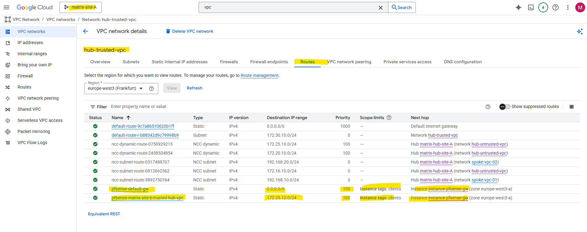
For workloads running directly in the trusted Hub VPC network, we can add a custom route for the Internet (0.0.0.0/0), where the next hop is our pfSense VPN instance (its LAN interface is attached to the trusted Hub VPC network).
To exclude pfSense itself to avoid routing loops and also workloads they should still use the native default internet gateway, we can use network tags on the VM instances (workloads), to set them as scope for the custom route. Only workloads where the scope is set to their corresponding network tag, will use this cutom route, all other will use the default internet gateway.
Each VPC network in GCP includes a default internet gateway, which automatically handles outbound traffic to the internet when a VM has an external IP assigned.
However, this gateway is implicit and not visible as a resource, it simply routes all 0.0.0.0/0 traffic from the VPC to the public internet unless overridden by a custom route or firewall policy.
Below I was also adding a custom route for the other sites spoke VPC network/subnet (172.25.10.0/24), the next hop is pointing also to pfSense. So all traffic destined to this subnet in the other NCC hub site, will be first routed directly to pfSense for further inspection and filtering.
We also set a scope to filter which workloads will use this route.
Finally, for every subnet in the other site, we add a custom route that points to our NGFW as the next hop, ensuring all traffic takes a quick detour through the firewall before heading out.
For our spoke VPCs, we can create custom routes to steer outbound or inter-site traffic through our NGFW appliane (pfSense) in the hub.
The recommended approach is to use an internal passthrough load balancer (ILB) in the trusted Hub VPC (where also the internal interface from our NGFW is attached to), its frontend IP acts as the next hop for the spoke routes, pointing traffic to the NGFW appliane (pfSense) for inspection.
Alternatively, in smaller or lab environments, we can also deploy gateway VMs with dual NICs (one in each VPC) to bridge traffic from the spoke to the hub, though this method sacrifices redundancy and manageability.
How to set up the recommended approach with the internal passthrough load balancer (ILB), you will find in my following post and directly here.
We also need to configure pfSense to reply to ILB Health Checks and shown in my following post.
Allow inbound Traffic on the VPC Networks
Finally, don’t forget that routing alone isn’t enough, the traffic we send through the VPN tunnel must also be explicitly allowed by the firewall rules in the VPC networks on the other site.
We need to permit the source subnets from the remote hub or spoke networks in the destination site’s VPC firewall rules (inbound/ingress), otherwise packets will be silently dropped even though the VPN tunnel is up and routing looks correct.
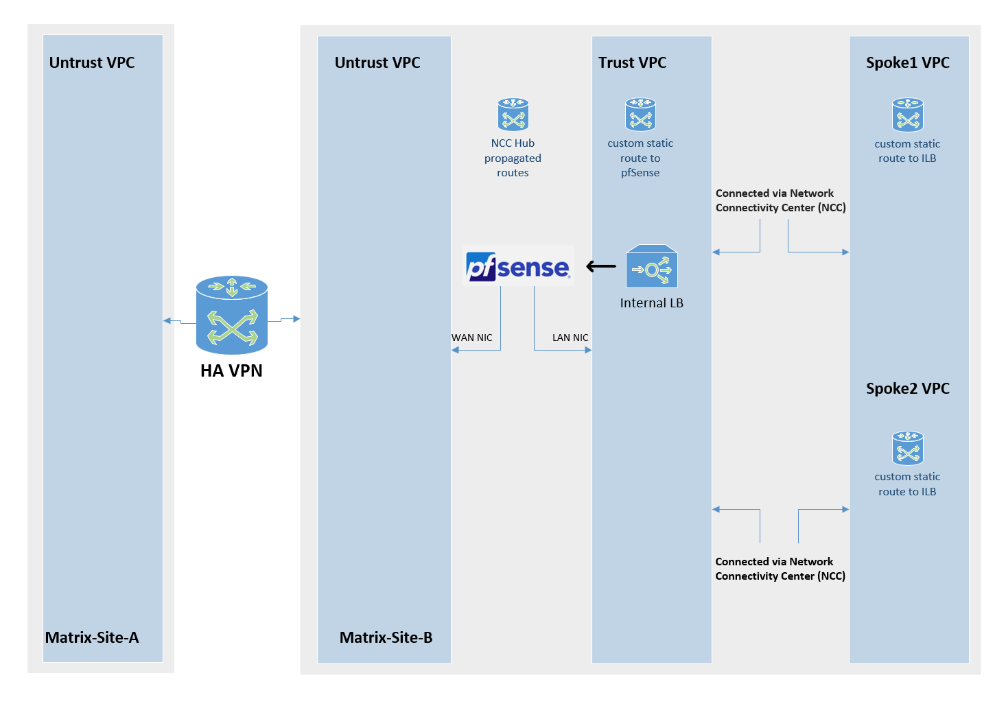
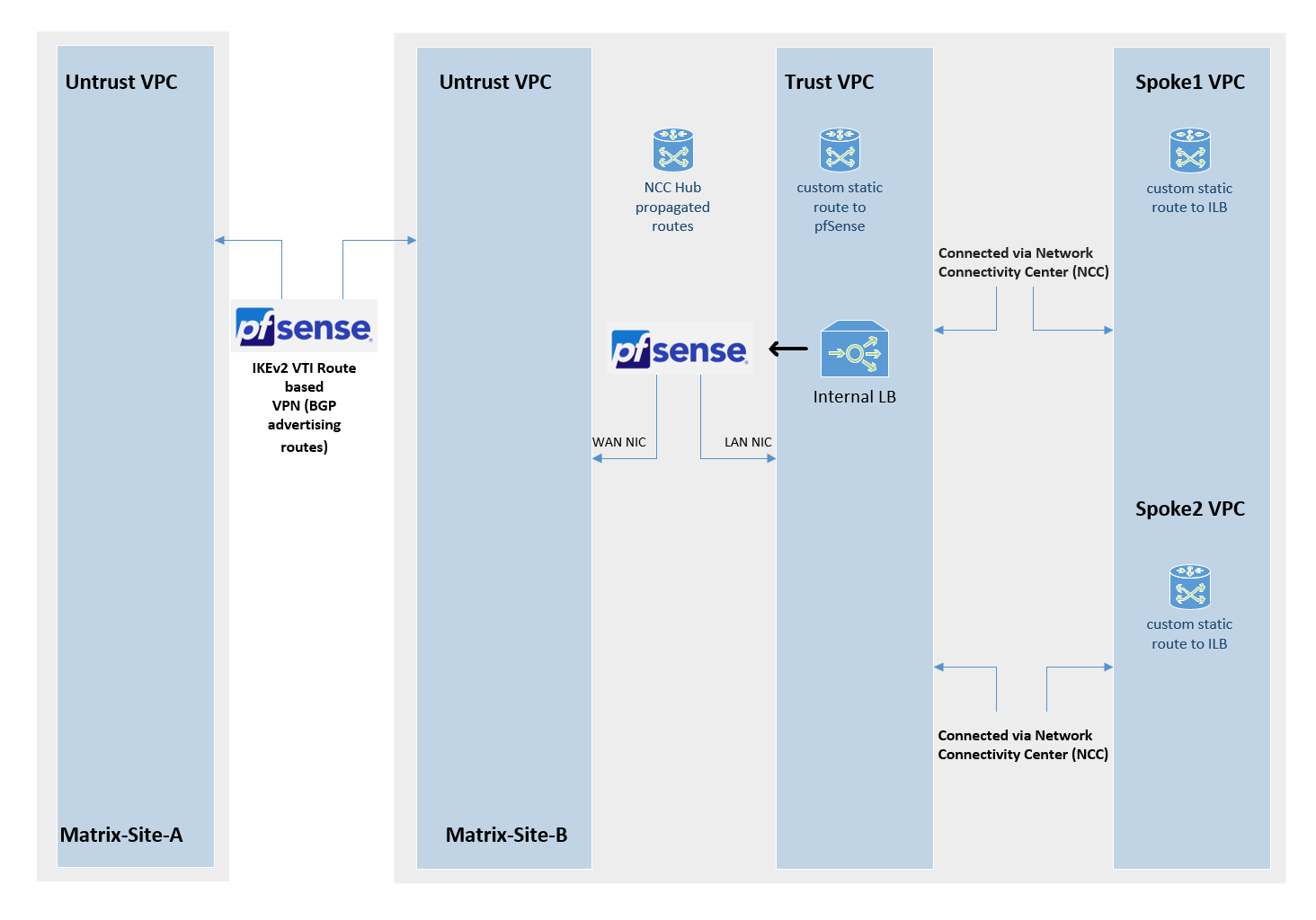
Below is a diagram of this architecture.
Using NGFW Appliances (pfSense) for both, Traffic Inspection and VPN Tunnel Connection
As mentioned to the beginning, instead using HA VPN to connect both NCC hub sites, we can also use our NGFW appliance (pfSense) to not just inspect traffic between both sides but also to establish the site-to-site VPN tunnel between both NCC hub sites.
About setting up a site-to-site IPSec VPN tunnel on pfSense, you can read my following post.
About setting up BGP on pfSense (finally Free Range Routing (FRR)), you can read my following post.
The following settings we need to perform to finally enable that traffic between both NCC hub sites can be successful routed
- set MTU 1460 on pfSense’s NIC interfaces (also for the VTI interface) to finally match with Google Cloud VPCs which using the MTU with 1460 bytes. pfSense 2.8 and later seems to support using the default MTU 1500. Anyway to be save I will also set it to 1460. More here.
- on the untrusted VPC Hub networks (pfSense’s WAN interface attached to) allow inbound UDP 500, 4500 traffic coming from the external public IP address of pfSense’s WAN NIC from the other site. When we adding a external public IP address in the GCP console to the WAN NIC, finally outbound Internet access is NATted by using this IP address.
For an IPsec tunnel to establish successfully between sites, each pfSense WAN interface, which in GCP has an assigned external (public) IP address, must allow inbound UDP ports 500 and 4500.
These ports are required for IKE (UDP 500) and NAT-Traversal (UDP 4500), which handle the negotiation and encapsulation of encrypted traffic.
If this inbound traffic is blocked on the VPC firewall associated with the WAN NIC’s external IP, the remote peer cannot reach the pfSense instance to complete IKEv2 negotiation, and the tunnel will fail to establish.
- on the trusted VPC Hub networks (pfSense’s LAN interface attached to) allow all inbound traffic from all VPC subnets (Hub trusted + Spoke) to pfSense. Finally pfSense will control allowed outbound traffic to the Internet and the other site.
- set a static route (0.0.0.0/0) on all internal VPCs where the next hop points to our pfSense appliance. Filter out pfSense itself by using network tags to avoid loops for pfSense itself. About setting the default route on Spoke VPCs to point to the internal IP of an appliance running in a different VPC (Hub VPC usually), you will see in my following post.
- set a static route on all internal VPCs you want to connect to the other site where the next hop also points to our pfSense appliance
- Allow desired inbound traffic on all Spoke VPCs coming from the other site (desired VPCs/subnets). The first place we will filter traffic coming from the other site is pfSense (Firewall -> Rules -> IPsec), but finally we also need to allow inbound/ingress traffic directly on the destination VPC firewall rules.
- Egress traffic by default is allowed an all VPC networks
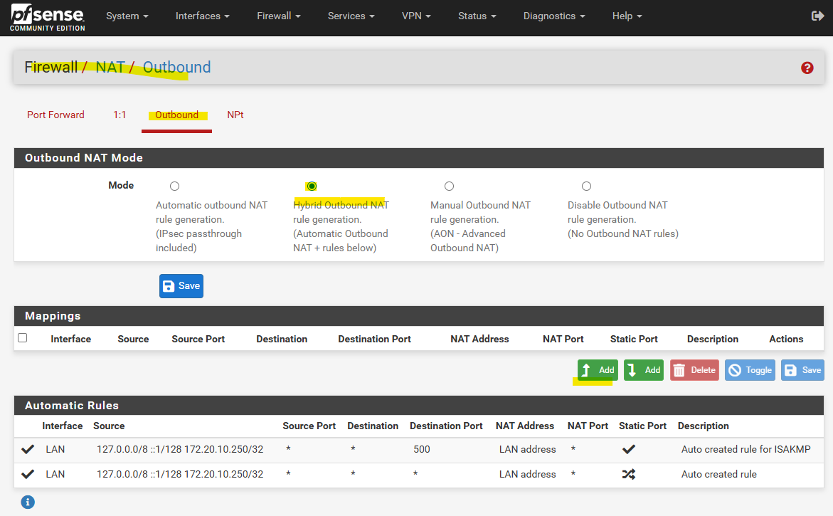
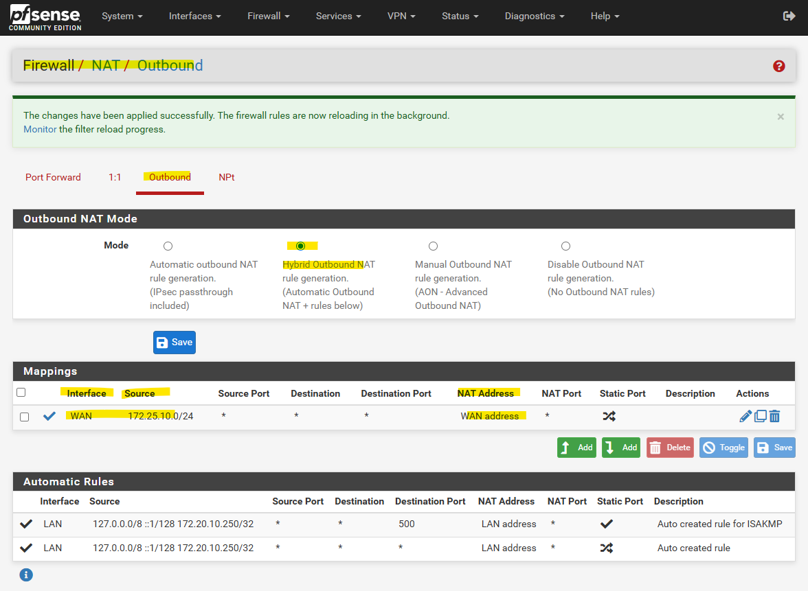
We also need to make sure, that pfSense will Nat all outbound traffic with its WAN address. If networks are not included by the default automatic outbound NAT rule, switch to Hybrid Outbound NAT rule generation and adding the required internal networks.
The default option, which automatically performs NAT from internal interfaces, such as LAN, to external interfaces, such as WAN.
Source: https://docs.netgate.com/pfsense/en/latest/nat/outbound.html
Select the WAN interface, for the Source select Network or Alias and enter the internal subnet (and its net mask), for which pfSense should NAT outbound traffic with its WAN address.
For natting all traffic leave the “Port or Range” field just blank.
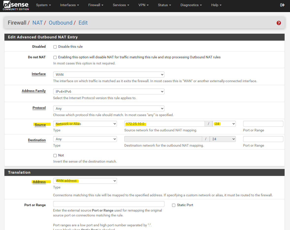
So from now on, also all outbound Internet traffic from VM instances running in the source subnet (172.25.10.0/24), will be natted by using pfSense’s WAN IP address.
Traffic routed between both sites through the tunnel are not affected and won’t be natted, they will be routed through the VTI interfaces.
Allow APIPA Traffic on pfSense
pfSense blocks APIPA traffic by default for security reasons.
To use APIPA-based transit networks successfully on pfSense, we must first enable APIPA traffic in the advanced system settings or by applying a short PHP command to disable the default block rule.
More about in my following post https://blog.matrixpost.net/pfsense-and-apipa-169-254-16-enabling-link-local-transit-networks-for-ipsec-vti-and-bgp/.
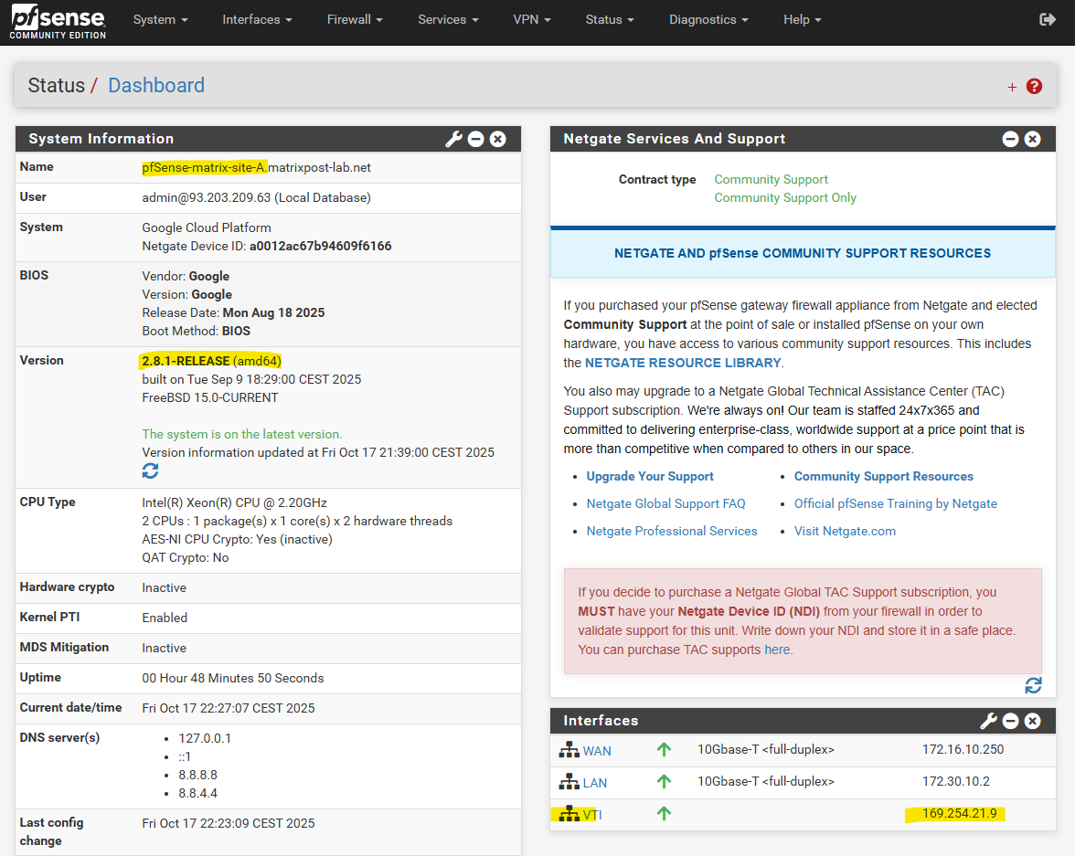
Issues with VTI interfaces running in GCP on pfSense version prior 2.8
In pfSense 2.7.2, the configured VTI interface for an IPsec tunnel in GCP remained without an assigned IP address (n/a), even though Phase 2 was connected, preventing BGP from establishing.
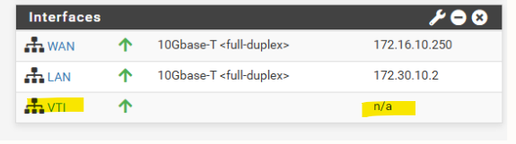
After upgrading to pfSense 2.8.1, the APIPA address was assigned to the VTI interface immediately after configuration without any further changes.
This behavior points to a VTI handling fix introduced in pfSense 2.8, improving reliability of interface creation and automatic IP assignment for route-based IPsec tunnels.
Below is a diagram of this architecture.
Links
Distributed, hybrid, and multicloud
https://cloud.google.com/docs/dhm-cloudCross-Cloud Network inter-VPC connectivity using Network Connectivity Center
https://cloud.google.com/architecture/ccn-distributed-apps-design/ccn-ncc-vpn-raHub-and-spoke network architecture
https://cloud.google.com/architecture/deploy-hub-spoke-vpc-network-topologyInternal passthrough Network Load Balancer overview
https://cloud.google.com/load-balancing/docs/internalInternal passthrough Network Load Balancers and connected networks
https://cloud.google.com/load-balancing/docs/internal/internal-tcp-udp-lb-and-other-networksCode Lab: NCC VPC as a Spoke
https://codelabs.developers.google.com/ncc-vpc-as-spokeHA VPN topologies
https://cloud.google.com/network-connectivity/docs/vpn/concepts/topologies