Set up IPSec route-based S2S VPN between pfSense and Google Cloud VPC
In this post I want to show how you can set up an IPSec route-based S2S VPN between your Google Cloud VPC and your on-premise network by using pfSense.
On Google’s site we can use therefore Cloud VPN which offers two types of Cloud VPN gateways: HA VPN and Classic VPN as described below.
As Classic VPN is partial deprecated, I will use HA VPN therefore.
Cloud VPN
HA VPN
HA VPN is a high-availability (HA) Cloud VPN solution that lets you securely connect your on-premises network to your VPC network through an IPsec VPN connection in a single region. HA VPN provides an SLA of 99.99% service availability.
When you create an HA VPN gateway, Google Cloud automatically chooses two external IPv4 addresses, one for each of its fixed number of two interfaces. Each IPv4 address is automatically chosen from a unique address pool to support high availability. Each of the HA VPN gateway interfaces supports multiple tunnels. You can also create multiple HA VPN gateways. When you delete the HA VPN gateway, Google Cloud releases the IP addresses for reuse. You can configure an HA VPN gateway with only one active interface and one external IP address; however, this configuration does not provide a 99.99% service availability SLA.
HA VPN supports the exchange of IPv6 traffic in Preview.
Source: https://cloud.google.com/network-connectivity/docs/how-to/choose-product#cloud-vpn
Classic VPN (partial deprecation)
To provide you with more reliable high-availability VPN connections, Google has replaced the dynamic routing, or Border Gateway Protocol (BGP),functionality of Classic VPN with HA VPN. Google encourages customers that use dynamic routing (BGP) to move to HA VPN, which became available in September 2019.
Certain Classic VPN functionality is deprecated. For more information, see Classic VPN partial deprecation.
Google encourages you to migrate your production traffic from Classic VPN to HA VPN wherever feasible.
Google also recommends that you retain Classic VPN when your on-premises VPN devices don’t support BGP and thus can’t be used with HA VPN. However, whenever possible, you should upgrade those devices to devices that support BGP. BGP is a more flexible and reliable solution than static routing.
Source: https://cloud.google.com/network-connectivity/docs/vpn/deprecations/classic-vpn-deprecation
Set up HA VPN
HA VPN requirements
- Configure two VPN tunnels from the perspective of the Cloud VPN gateway:
- If you have two peer VPN gateway devices, each of the tunnels from each interface on the Cloud VPN gateway must be connected to its own peer gateway.
- If you have a single peer VPN gateway device with two interfaces, each of the tunnels from each interface on the Cloud VPN gateway must be connected to its own interface on the peer gateway.
- If you have a single peer VPN gateway device with a single interface, both of the tunnels from each interface on the Cloud VPN gateway must be connected to the same interface on the peer gateway.
- A peer VPN device must be configured with adequate redundancy. The device vendor specifies the details of an adequately redundant configuration, which might include multiple hardware instances. For details, see the vendor documentation for the peer VPN device.
If two peer devices are required, each peer device must be connected to a different HA VPN gateway interface. If the peer side is another cloud provider like AWS, VPN connections must be configured with adequate redundancy on the AWS side as well. - Your peer VPN gateway device must support dynamic (BGP) routing.
The following diagram shows the HA VPN concept, showing a topology that includes the two interfaces of an HA VPN gateway connected to two peer VPN gateways. For more detailed HA VPN topologies (configuration scenarios), see Cloud VPN topologies.
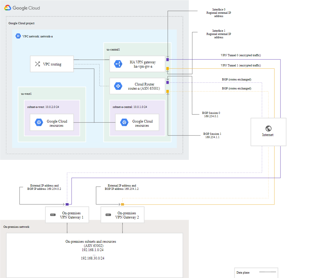
HA VPN requirements
https://cloud.google.com/network-connectivity/docs/vpn/concepts/overview#ha-requirementsCreate an HA VPN gateway to a peer VPN gateway
https://cloud.google.com/network-connectivity/docs/vpn/how-to/creating-ha-vpn
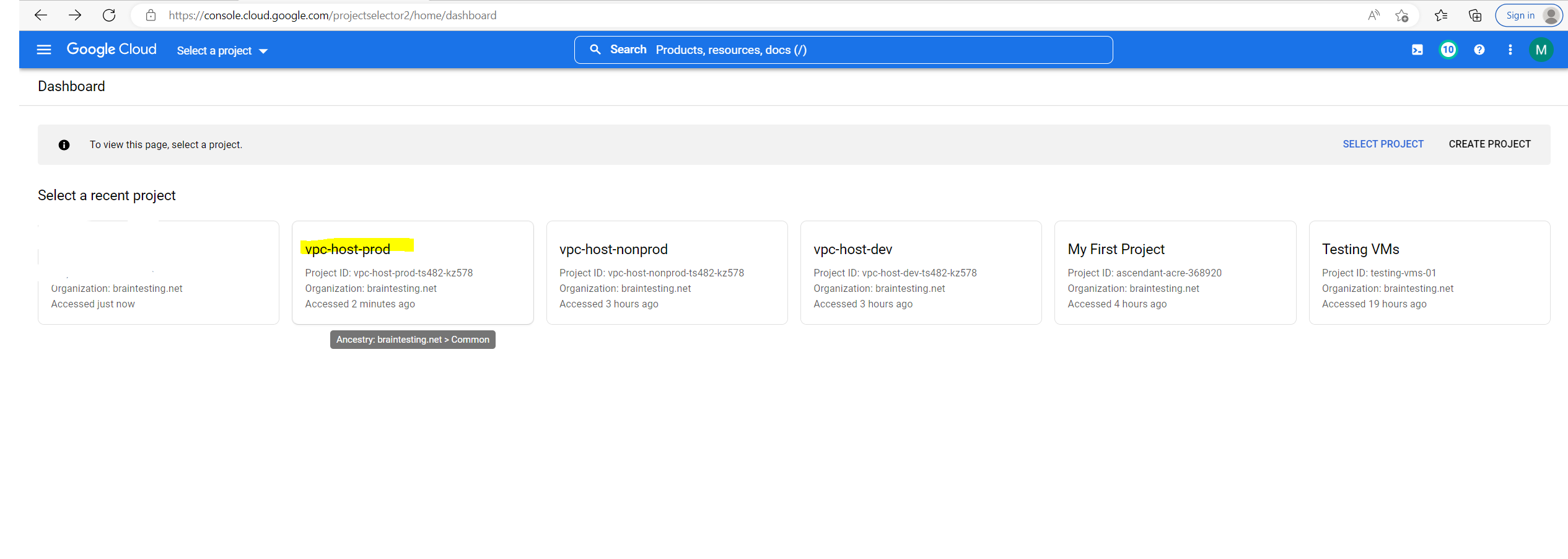
Select or Create a Project to deploy the HA VPN gateway
In the Google Cloud console, open the project selector page at https://consolhttps://console.cloud.google.com/projectselector2/home/dashboarde.cloud.google.com/projectselector2/home/dashboard and select an existing project to deploy the HA VPN gateway or create a new project for.
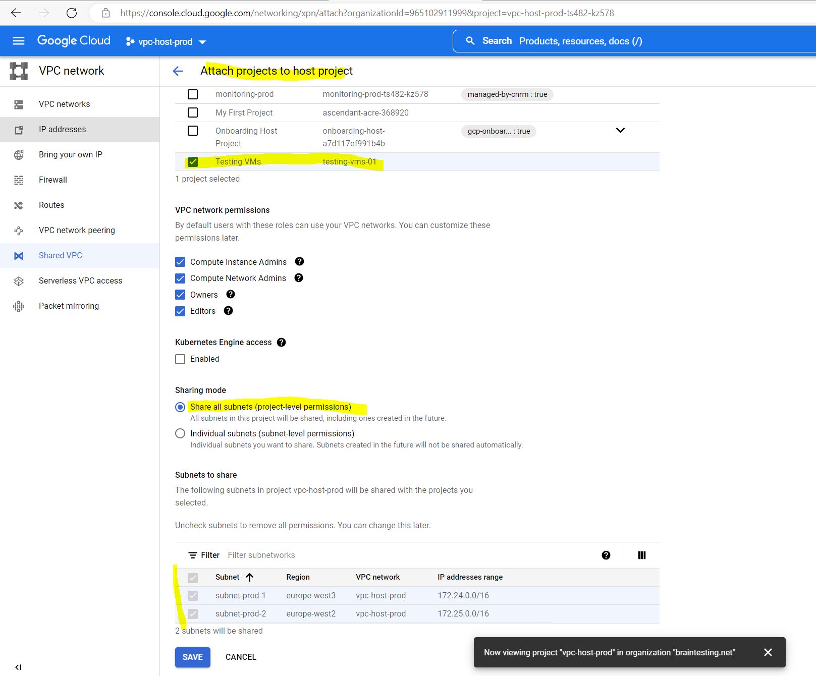
I want to use my Shared VPC network for the VPN tunnel and therefore I will deploy the VPN gateway to this Shared VPC.
This Shared VPC network I was set up during the organization setup as described in my following post.
Set up your Organization for Google Cloud
https://blog.matrixpost.net/set-up-your-organization-for-google-cloud
You can of course also use each other VPC network or create a new one to deploy the VPN gateway to, it depends on your requirements and environment especially as an organization setup is optional.
vpc-host-prod is the host project where the Shared VPC network (production environment) was deployed.
Make sure that billing is enabled for your Cloud project. Learn how to check if billing is enabled on a project.
You can also create a custom VPC network and subnet to deploy the vpn gateway.
Before creating an HA VPN gateway and tunnel pair, create a Virtual Private Cloud (VPC) network and at least one subnet in the region where the HA VPN gateway resides.
Source: https://cloud.google.com/network-connectivity/docs/vpn/how-to/creating-ha-vpn
I will use below the GCP console to set up the VPN tunnel on Google site, you can also use the Google Cloud CLI therefore.
Create an HA VPN gateway
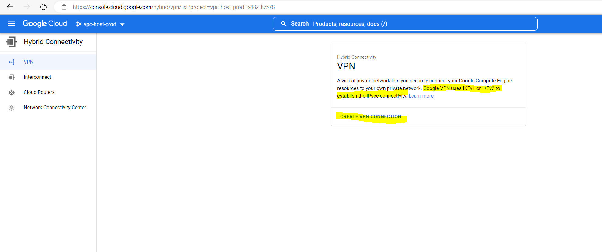
In the Google Cloud console, go to the VPN page.
Networking –> Hybrid Connectivity –> VPN

Cloud VPN overview
https://cloud.google.com/network-connectivity/docs/vpn/concepts/overview
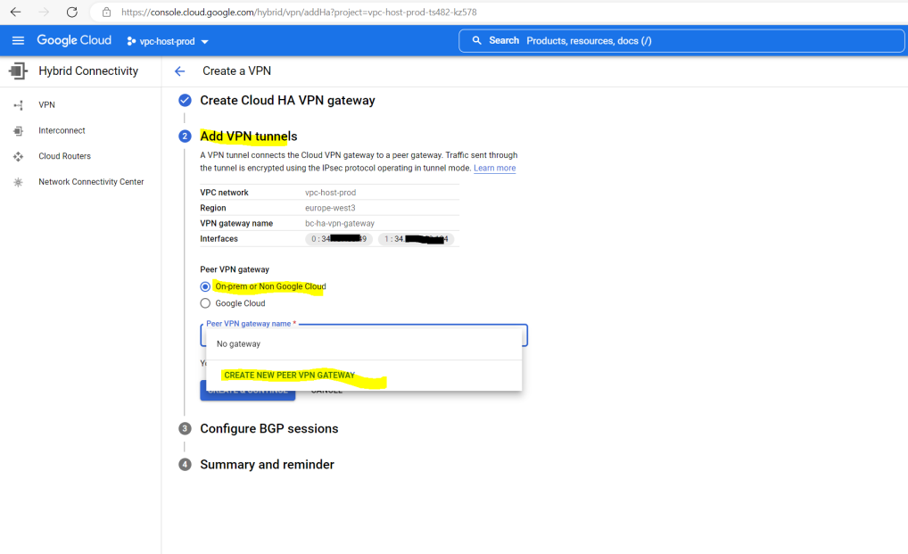
At the VPN setup wizard select High-availability (HA) VPN

We need to provide a name for the VPN gateway. Further we need to select the VPC network, the VPN tunnel will get connected to. As already mentioned I will use here my productive Shared VPC network which I was set up for the organization.

Here I have to add my on-premise pfSense peer vpn gateway.
I will just use one interface and public IP address on pfSense.
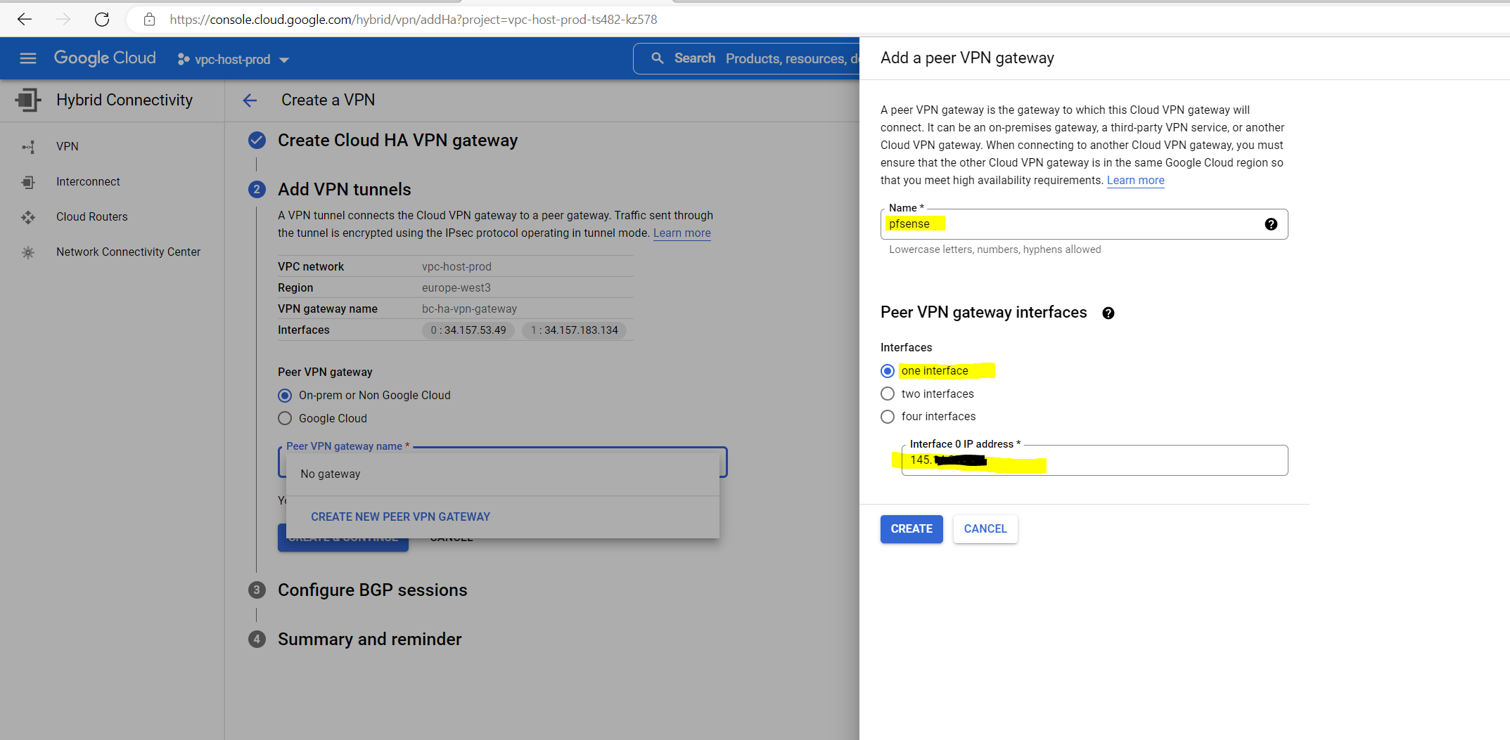
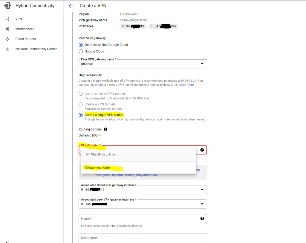
We also need to create a cloud router at google’s site.
The cloud route here is the BGP speaker or service in GCP.
For testing purpose I will first only configure a single VPN tunnel. I will show at the end of this post how to add a second tunnel to an existing VPN gateway configuration.
A pair of VPN tunnels is required if you want the high availability and 99.99% uptime SLA
Therefore I have to select one of the available VPN gateway interfaces below, here the one with the id:0 I will use for my single VPN tunnel and as mentioned later the second one with the id:1.
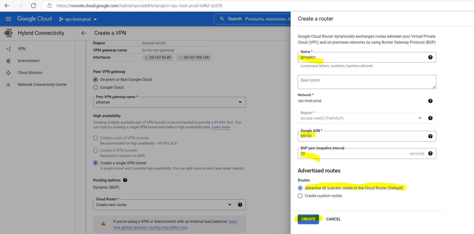
Below we need to provide a custom ASN.
You can use here a number from the reserved private use range which is from 64512 – 65534.
I will use here 65100 for the cloud router. Further you need to enter the BGP peer keepalive interval, I will use the default 20 seconds.
More about Autonomous system (Internet)
https://en.wikipedia.org/wiki/Autonomous_system_(Internet)
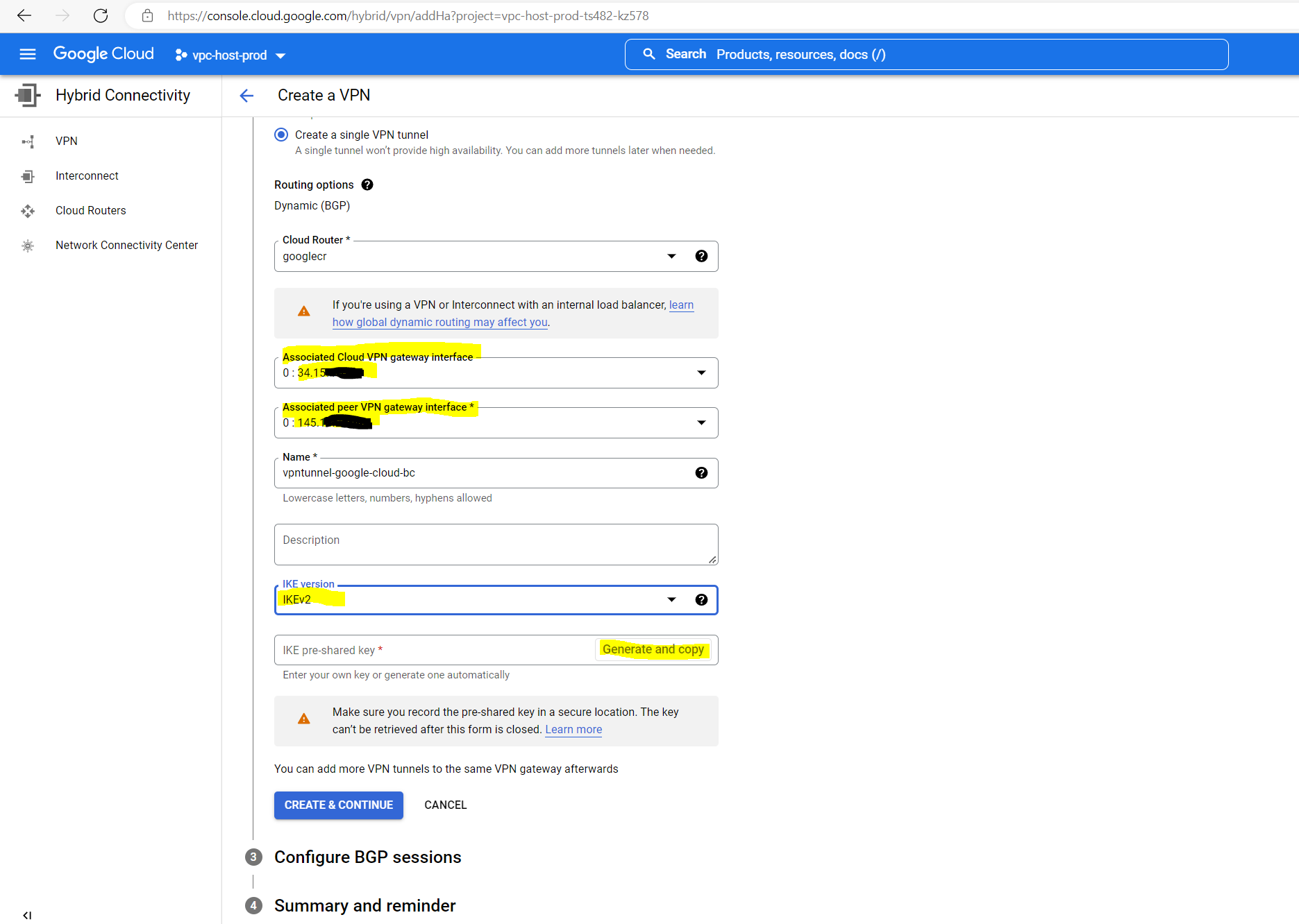
Below you can see the public IPv4 address from the Cloud VPN gateway’s interfaces and my on-premise pfSense (peer VPN gateway interface).
As already mentioned I will create just a single VPN tunnel first and therefore just select one interface for, the one with id:0.
You can also let Google create the IKE pre-shared-key to use with pfSense.
Make sure that you record the pre-shared key in a secure location because it cannot be retrieved after you create your VPN tunnels.
For the IKE version we use IKEv2. HA VPN wil support both, IKEv1 and IKEv2.
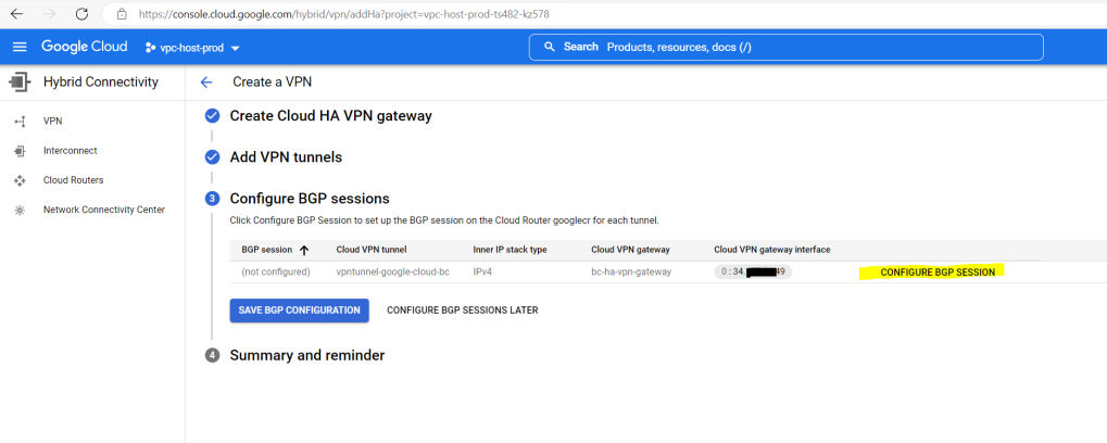
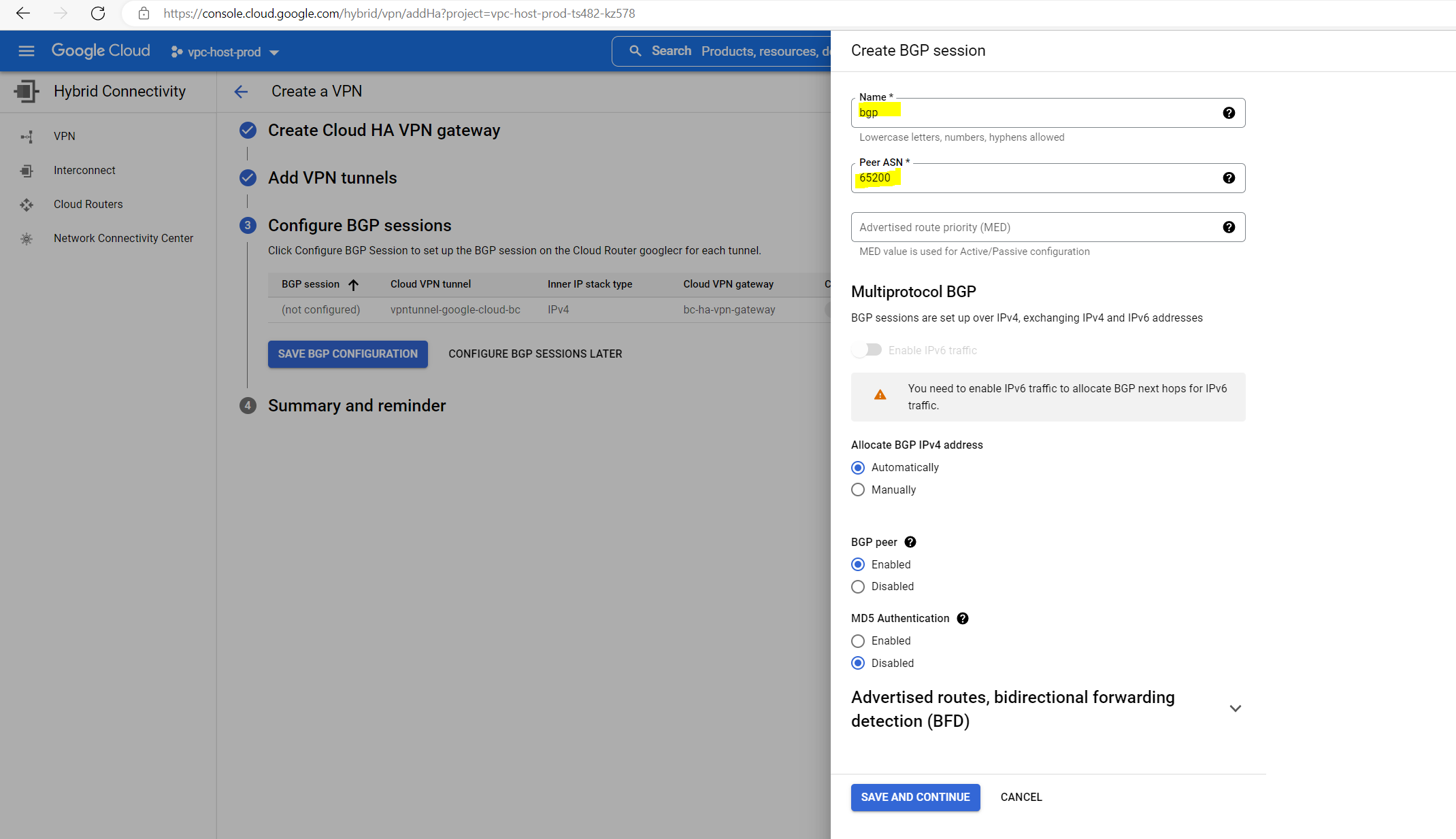
Here we need to configure BGP on the cloud router.
Further down I will have to enter the peer ASN (my pfSense appliance) and the Advertised route priority (MED). For my pfSense appliance I will use the ASN 65200 and if I don’t specify a base priority, the default with 100 is used.
Based priorities let you control which Cloud VPN tunnel your on-premise systems use to send packets to your VPC network. You can create active/active, active/passive, or a custom combination of these topologies by using the base priority. For an example using HA VPN tunnels, see Active/active and active/passive routing options for HA VPN in the Cloud VPN documentation.
When a router has multiple links to the same AS, the MED value influences which path the router will prefer.
You can configure by the way also the Advertised route priority (MED) in pfSense (FRR) by using a route map as shown in the following article from Netgate https://docs.netgate.com/pfsense/en/latest/packages/frr/global/routemaps.html#metric.
So in my case as I just had one tunnel (link) configured to connect my on-premise network with the VPC, the priority doesn’t matter here.
Advertised prefixes and priorities
https://cloud.google.com/network-connectivity/docs/router/concepts/overview#advertised-prefixes-and-prioritiesWhen a Cloud Router advertises prefixes to a BGP peer, it includes a priority for each prefix in the advertisement (BGP message). The advertised priority is implemented as a Multi Exit Discriminator (MED).
Base priorities are whole numbers from 0 to 65535. The highest possible base priority is 0. The default base priority is 100. If you don’t specify a base priority, the default priority is used.
The rest of the settings I will leave at default.
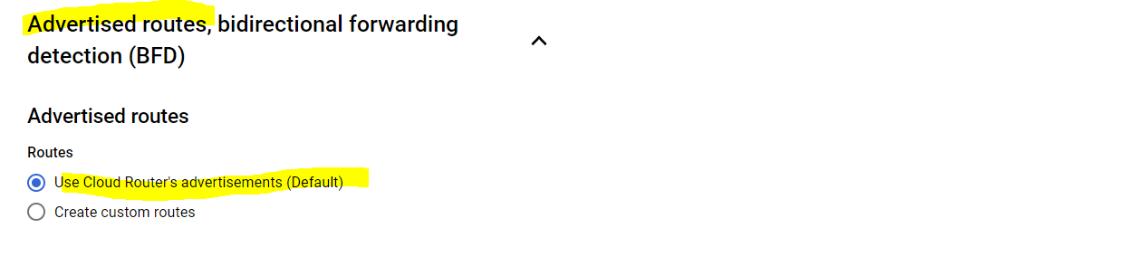
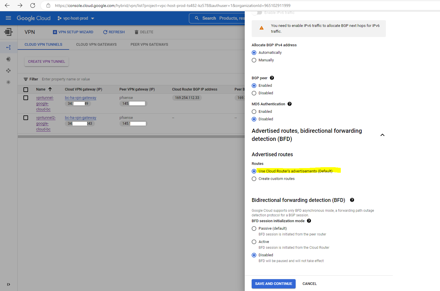
Under Advertised routes we can control which routes will be advertised to our on-premise peer (pfSense) by checking Create custom routes. I will leave the default settings.
Route advertisement modes
https://cloud.google.com/network-connectivity/docs/router/concepts/overview#route-advertisement
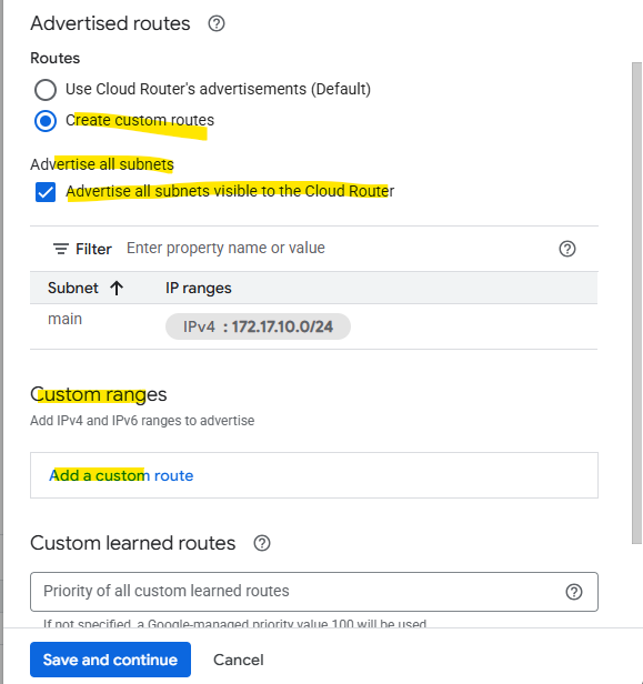
To add custom routes we need to select below “Create custom routes”.
When checking Advertise all subnets visible to the Cloud Router it means ==> The routes that are all prefixes that the Cloud Router currently knows about within its scope, which depends on its associated VPC network, its region and the routing mode (regional or global dynamic routing).
The screenshot is from a different deployment.
Which routes finally will be advertised to the BGP peer (on-prem here) we will see on the Cloud Router tab below. We can also switch the route direction to see the learned routes from our BGP peer.
The screenshot is also from a different deployment.
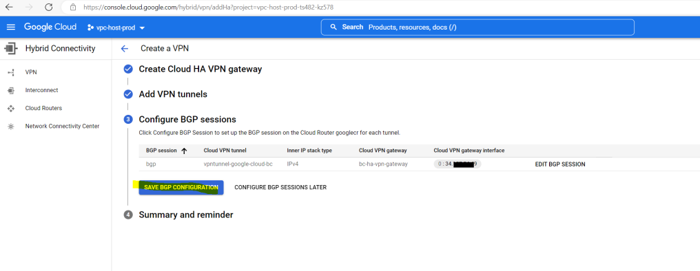
Now I can save the BGP configuration.
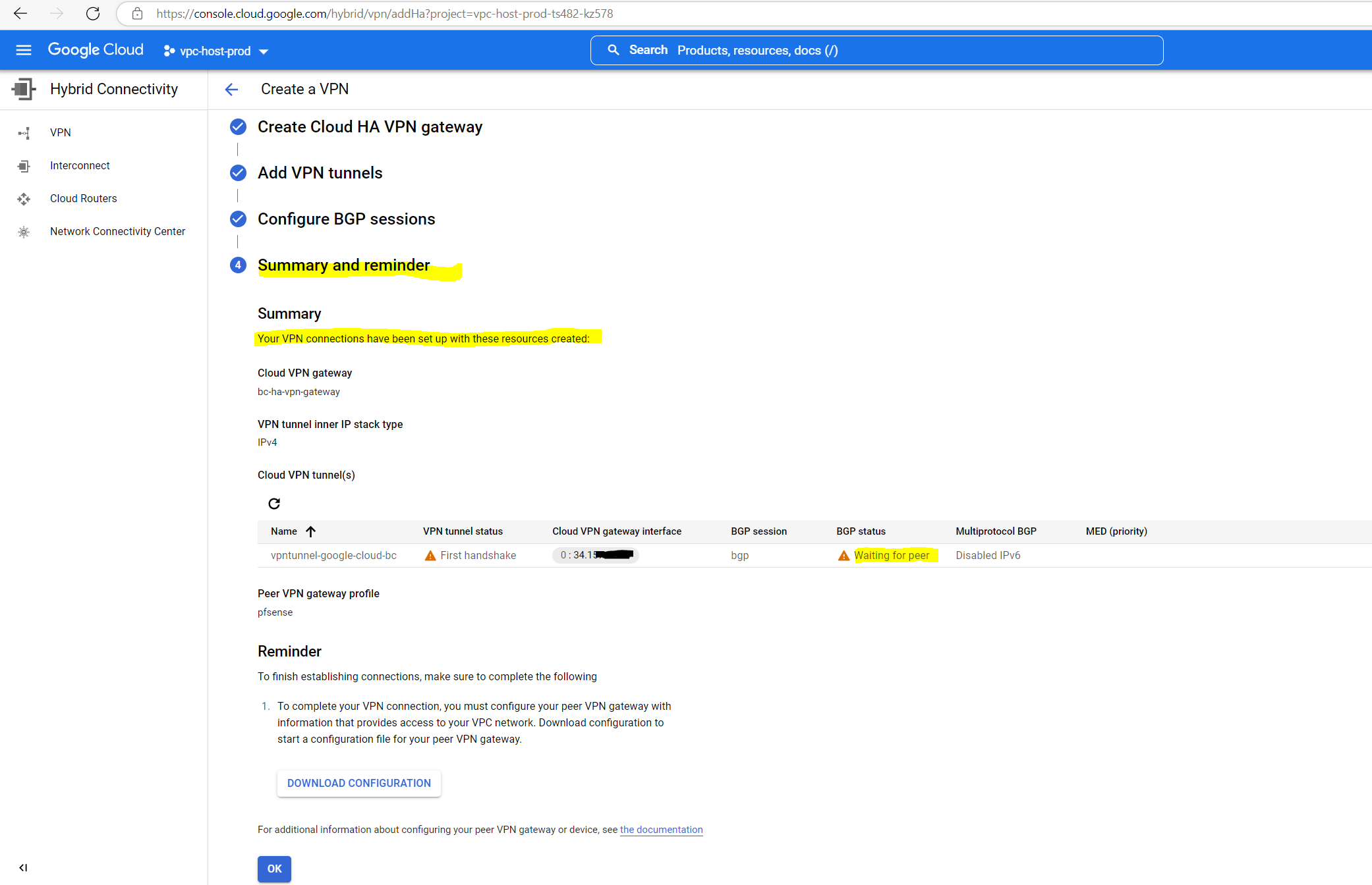
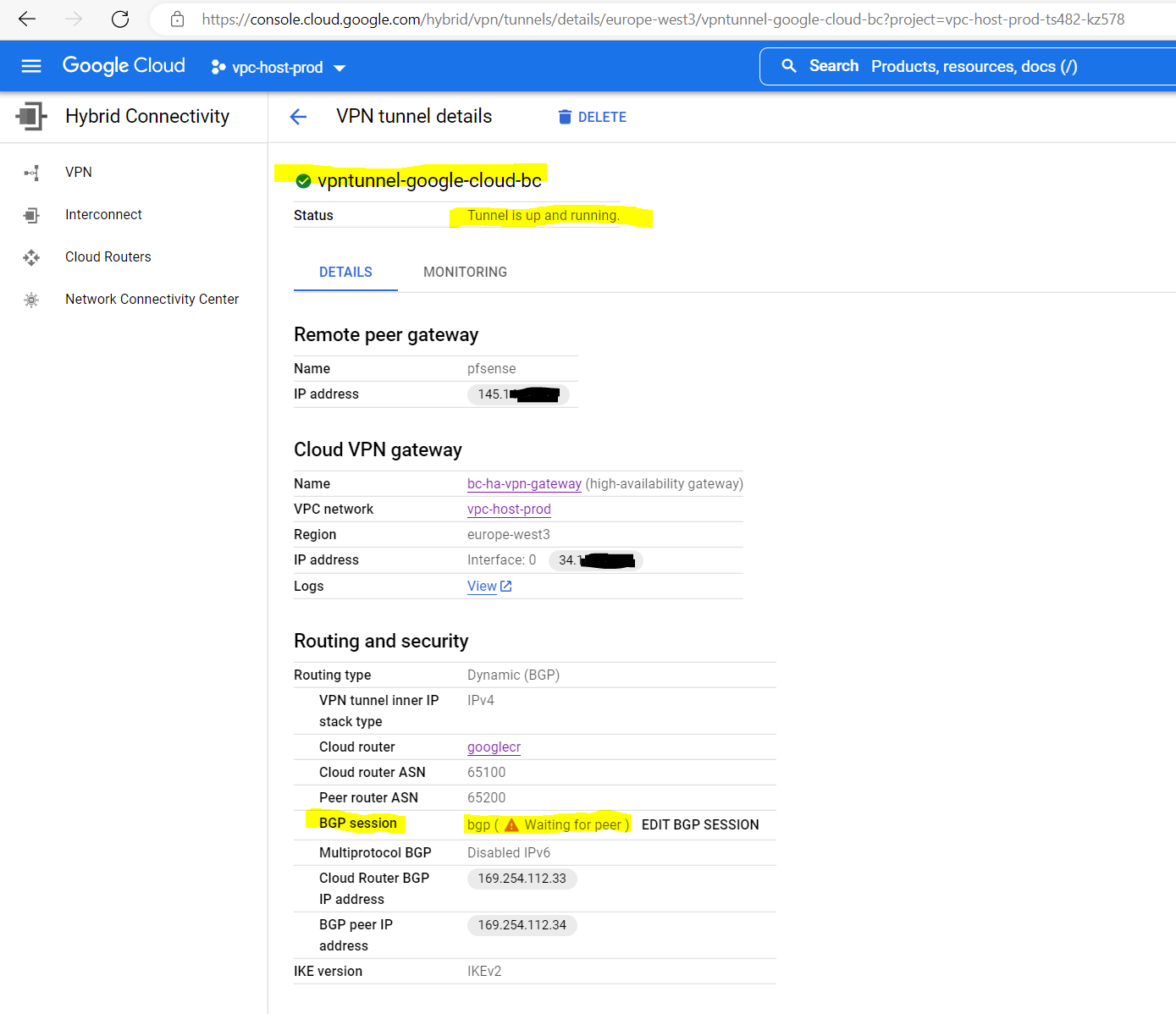
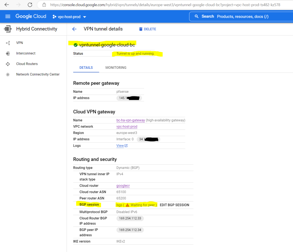
So far the VPN tunnel has been set up and is of course in BGP status Waiting for peer as I now first need to set up the tunnel on pfSense in my on-premise network.
Set up the IPSec Tunnel on pfSense
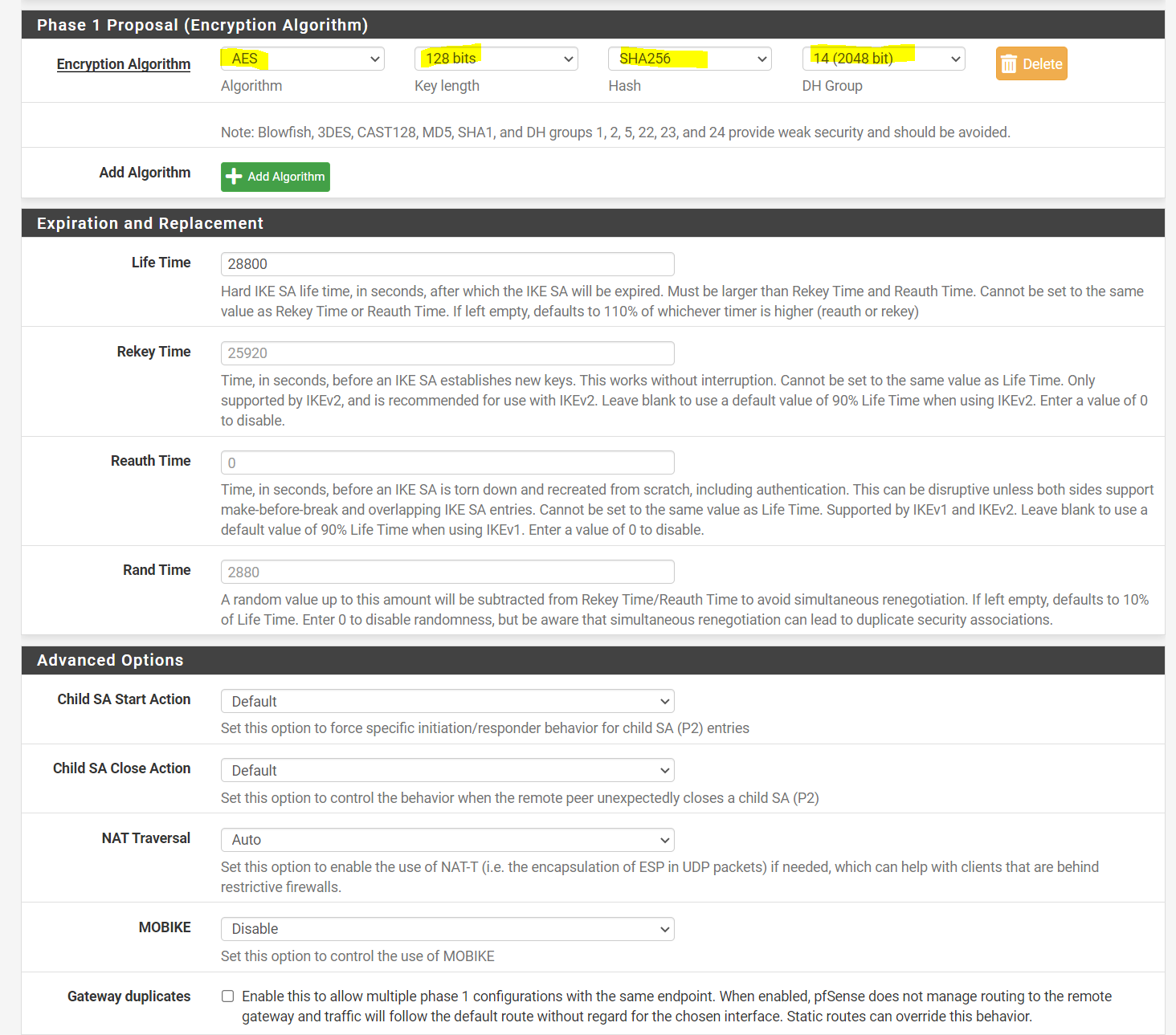
Now I have to configure Phase 1 and Phase 2 on pfSense in my perimeter network. First we will add a phase 1.
pfSense –> VPN –> IPSec –>Add/Edit Phase 1


Regarding what IKE ciphers are supported by Google’s Cloud VPN, you can read the following article from Google.
Supported IKE ciphers
https://cloud.google.com/network-connectivity/docs/vpn/concepts/supported-ike-ciphers
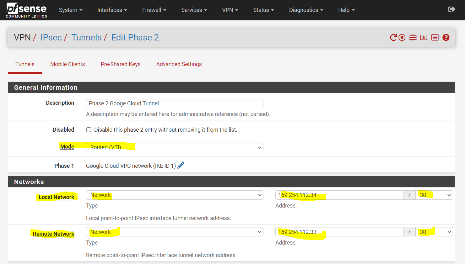
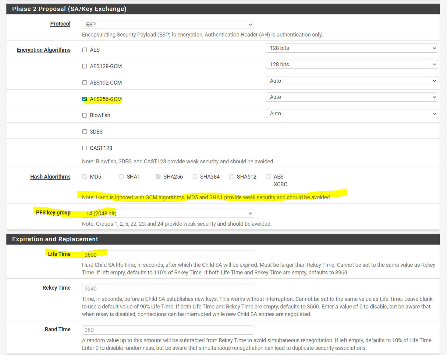
Now we can add the IPSec/EPS phase 2 tunnel. For Mode below we need to use here Routed(VTI).
By using this pfSense will create a virtual tunnel interface and attach it to the IPSec/EPS phase 2 tunnel (aka transit network), to this tunnel interface we need to assign an IP address (out of an /30 subnet) which is required to route traffic for BGP between both peers, also the actual routed subnets will be routed through this interface.
BGP/OSPF is based on Layer 3 reachability between the two peers. BGP is a routing protocol that needs to form a TCP session (TCP port 179) between two IP addresses.
More about you will find here by using Juniper as on-prem VPN device, but finally the same in pfSense.
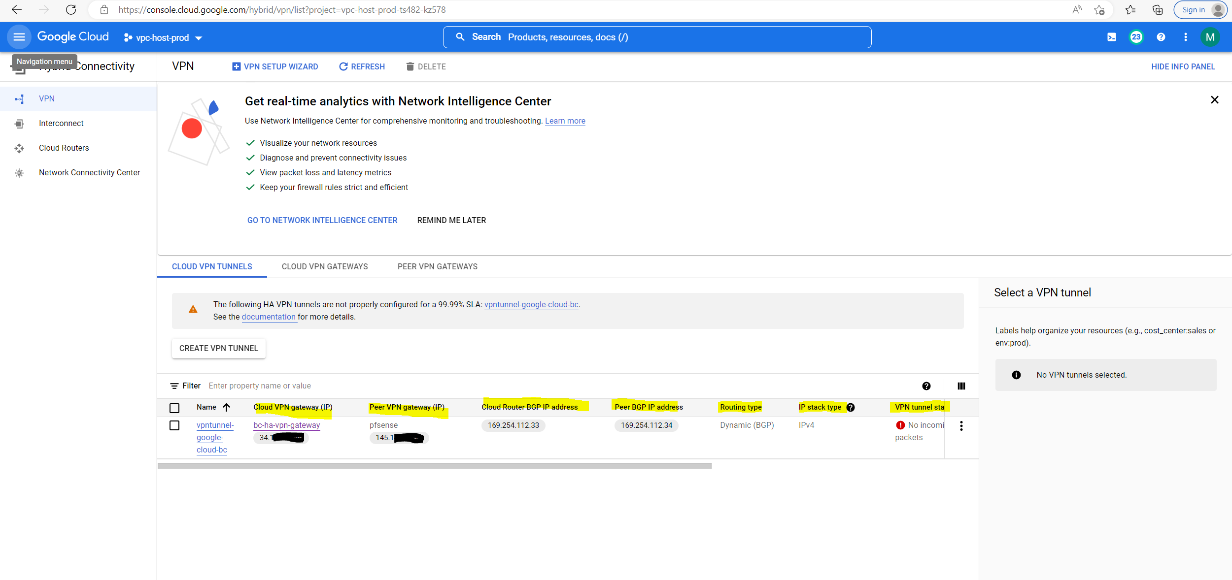
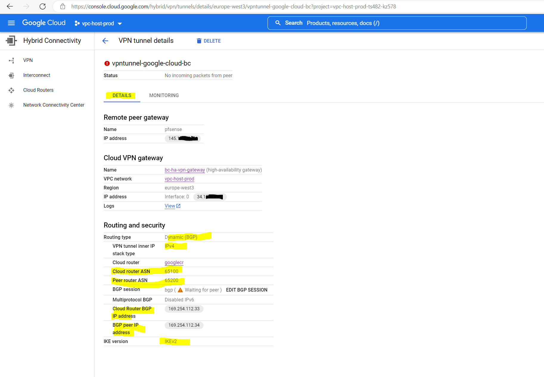
The IPs we need to use for this transit network below we get from the tunnel details page in the GCP console.
After that we can check if the tunnel is established under
pfSense –> Status –> IPSec
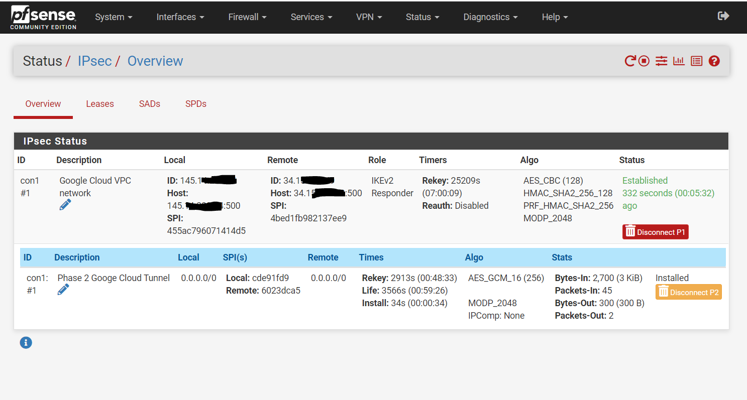
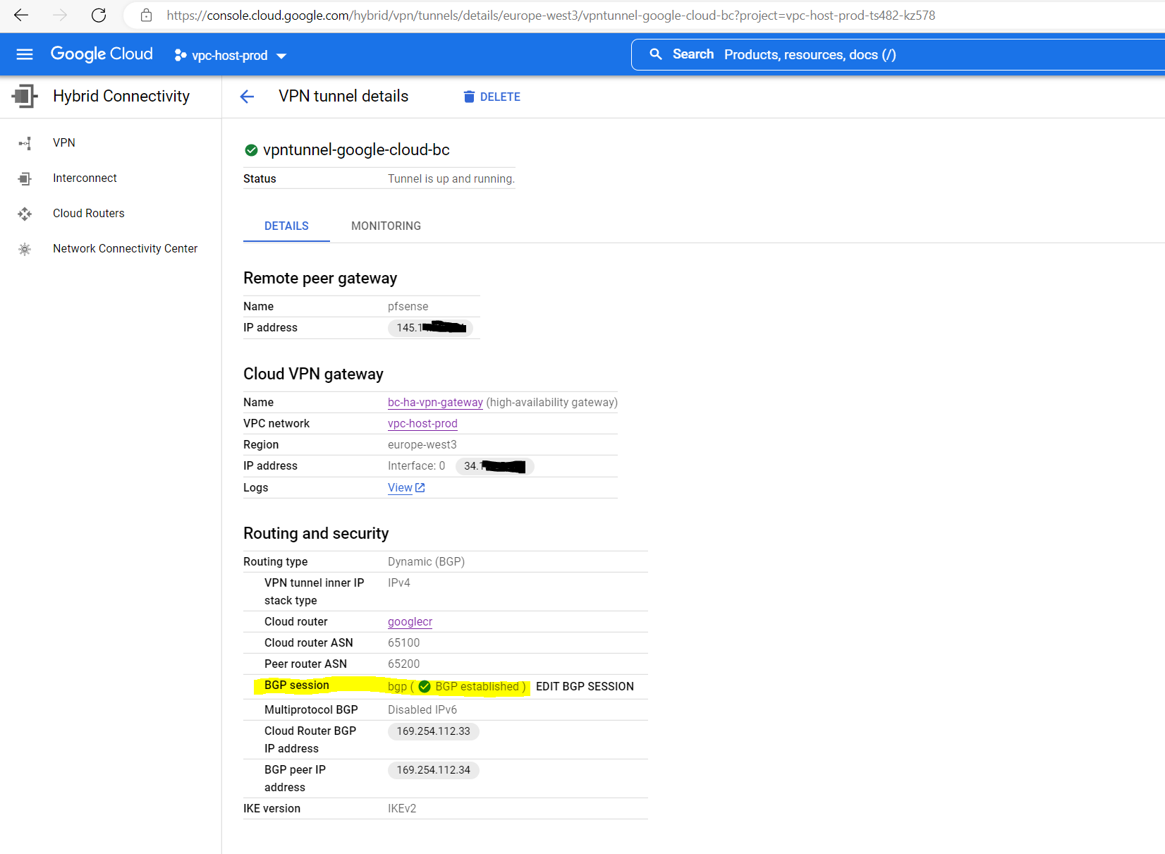
We will see also the status in the GCP console. Just BGP so far is not established.

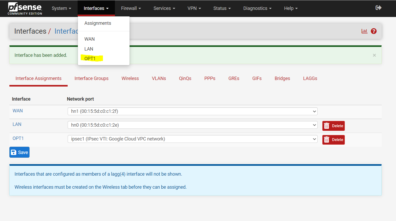
That routing in pfSense finally works over the IPSec tunnel, we have to assign the IPSec Interface (VTI) which was automatically created after set the Tunnel Mode to Routed(VTI) in the Phase 2 settings.
Therefore go to the menu Interfaces – Assignments and add the ipsec Interface as follows.

After the assignment you will find this interface with the name OPT1. I changed the name to IPSecVTI for a better understanding.
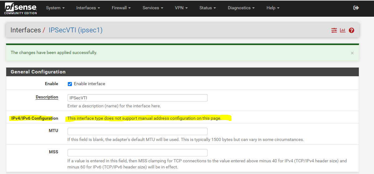
Per default the interface is not enabled, so don’t forget to also enable it!
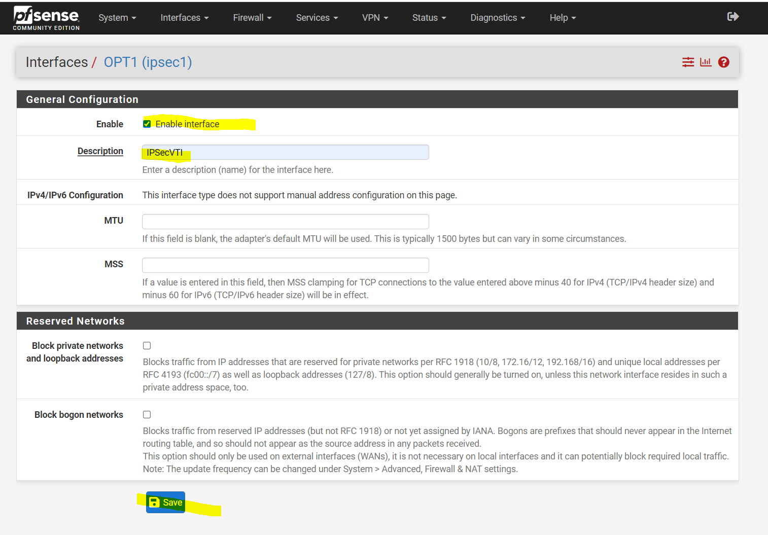
As you can read below, we cannot set manual an IP Configuration. The interface will get automatically an IP from the previous created transit network. This IP will represent the gateway to reach our Google Cloud Shared VPC network.
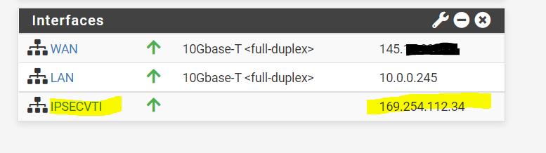
You can see the automatically assigned IP from the phase 2 tunnel local subnet on the status page (Dashboard) from pfSense.
Under System – Routing the Interface is automatically added as Gateway.

We also need to allow traffic between the Google Cloud VPC and our on-premise network, in my case for testing I will allow all IPv4 traffic, in production use you will filter what is allowed.
Firewall –> Rules –> IPSec

The firewall rules for the IPsec tunnel should also allow the BGP protocol/service which is using and listening on TCP Port 179 and should not be blocked by the firewall.
Configure BGP (FRR) on pfSense
Now as the tunnel is established, we also need to configure BGP on pfSense. Therefore you can use my following post. For the peer ASN for pfSense I will use 65200 as set above at the Google Cloud router for.
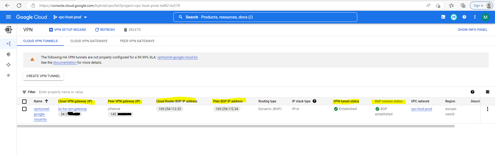
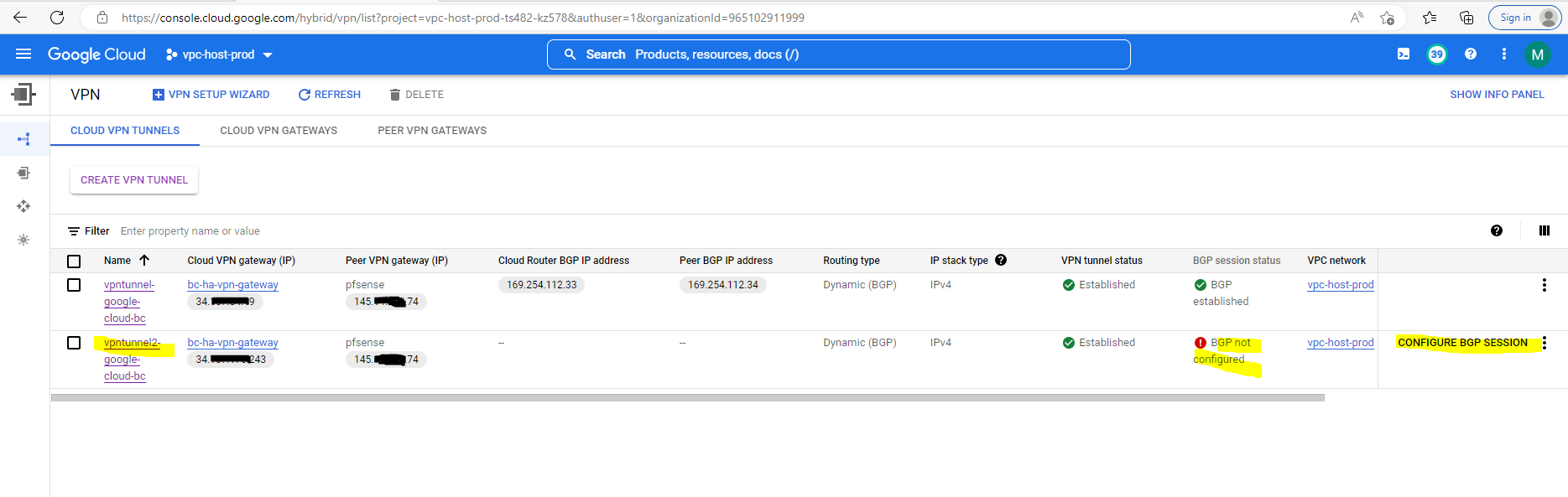
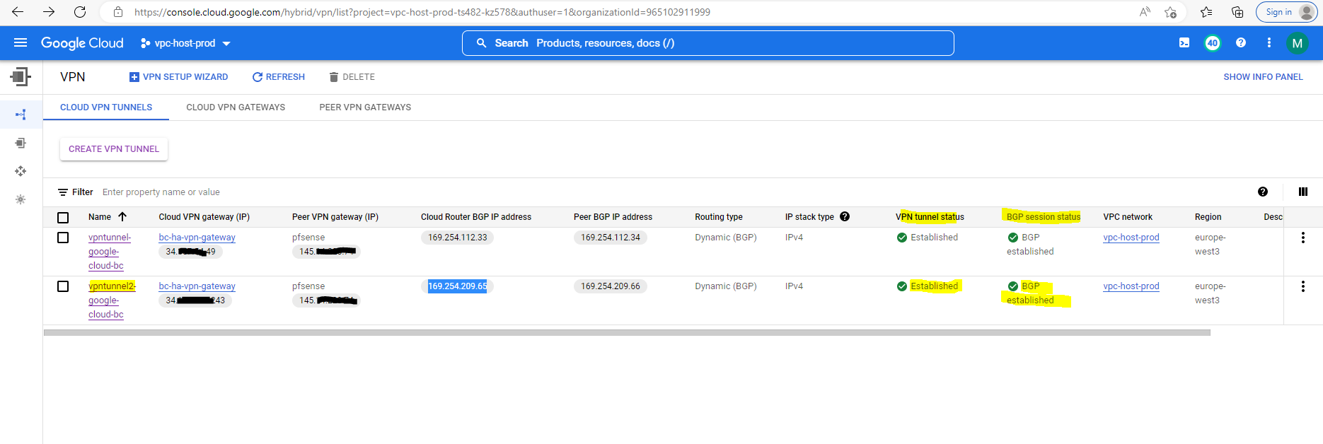
You can also check in the GCP Console if the BGP session is established.
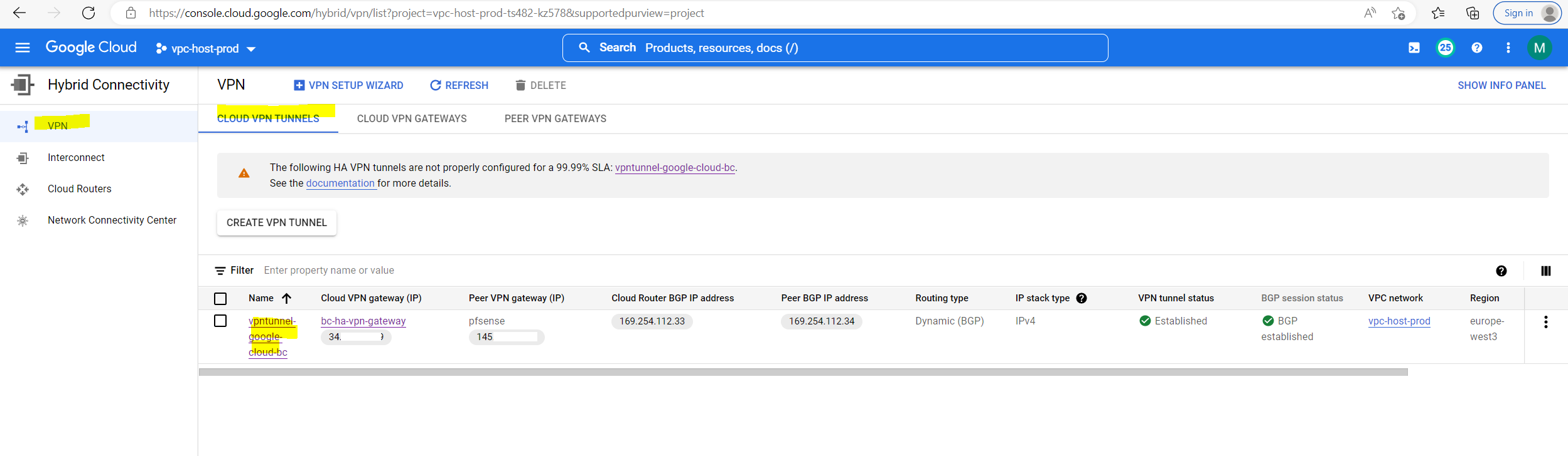
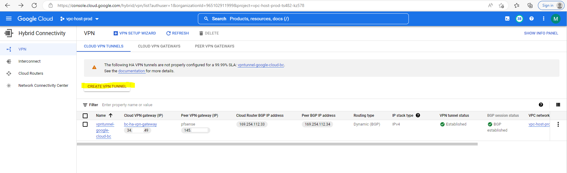
So far I just set up one VPN tunnel for testing purpose and therefore you will see the following warning message in the GCP console. We will later in this post add a second tunnel to our configuration so that this warning message will disappear.
The following HA VPN tunnels are not properly configured for a 99.99% SLA: vpntunnel-google-cloud-bc.
See the documentation for more details.
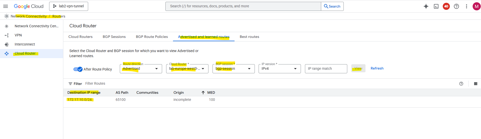
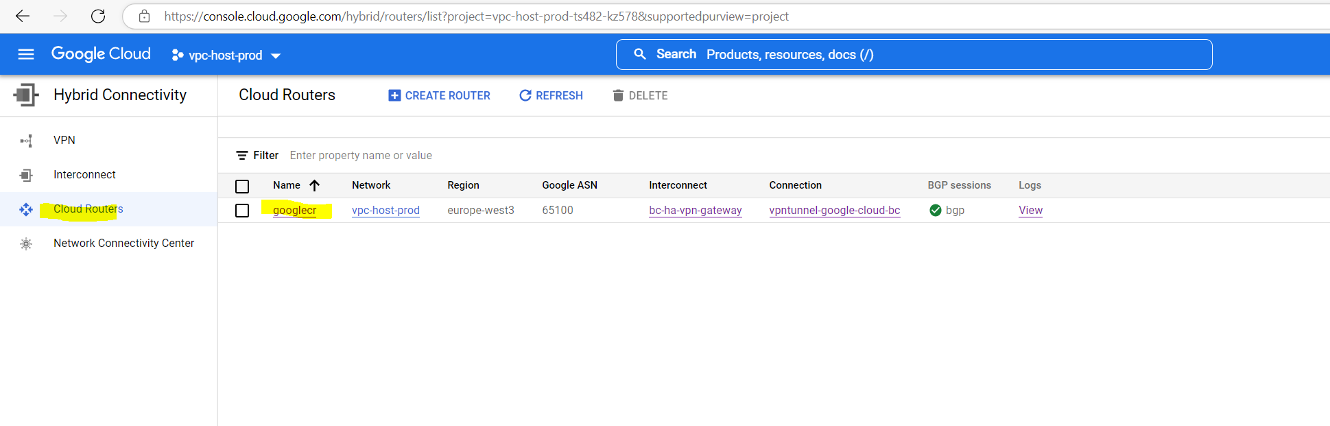
If you want to see what routes the Google cloud router will advertise to your on-premise router (pfSense), you can see them at the following panel.
GCP console –> Hybrid Connectivity –> Cloud Routers
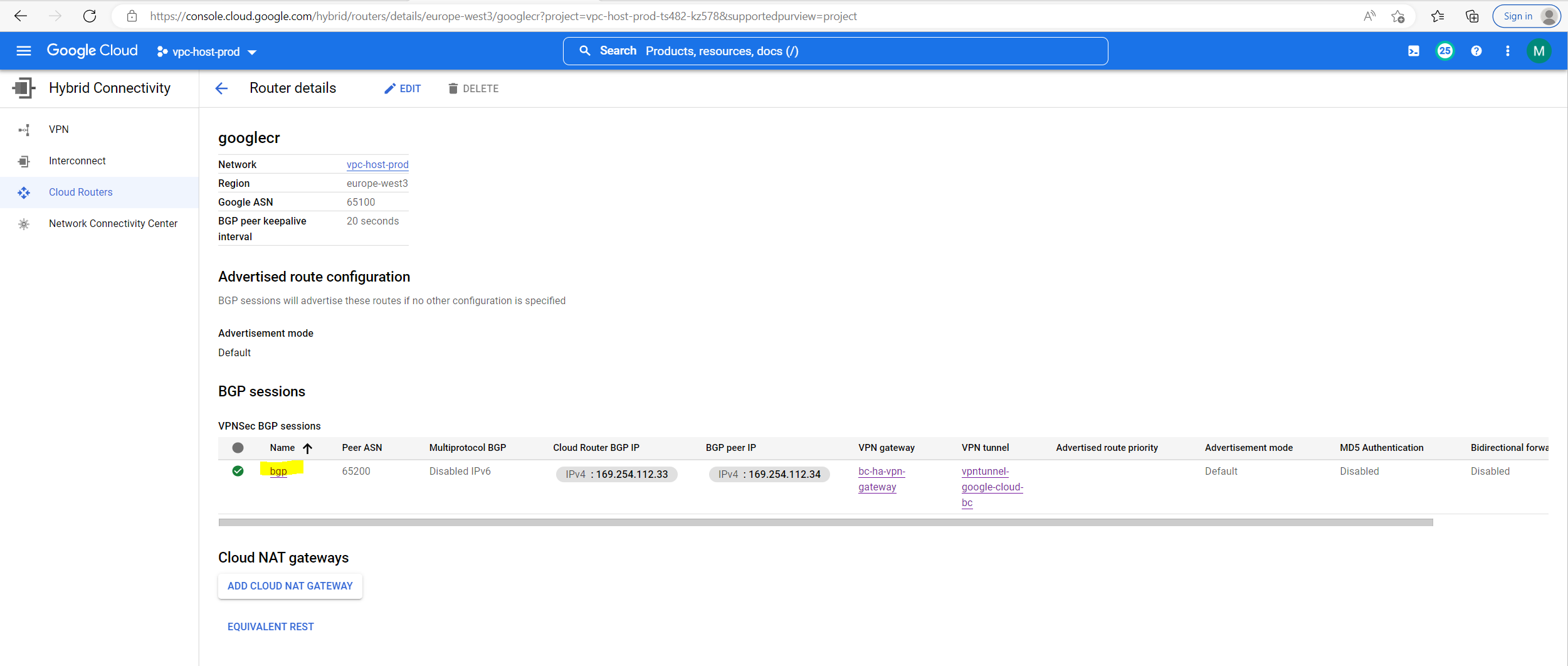
Click on your cloud router, in my case googlecr
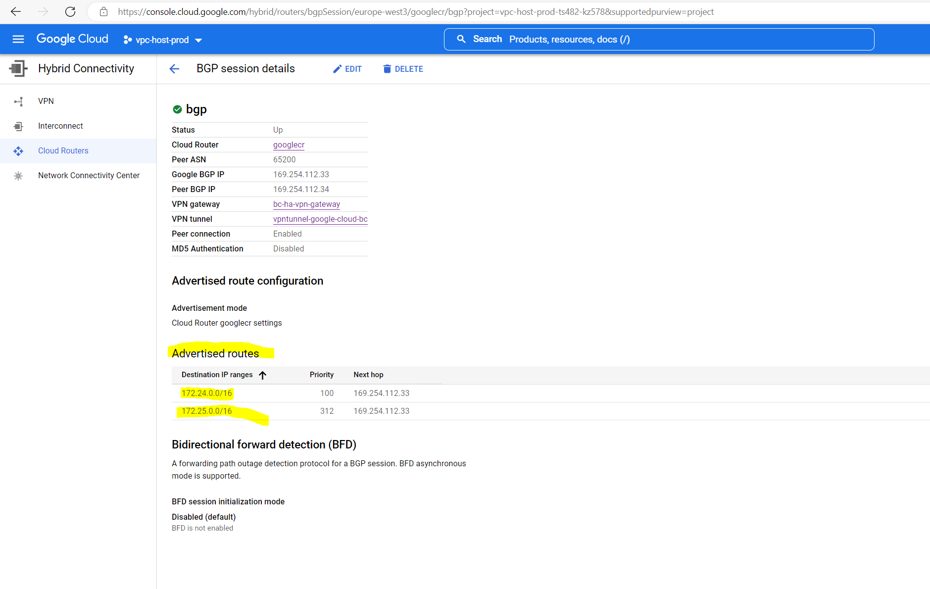
Then click on the name of your BGP session, in my case bgp
Below you will see that both subnets from my productive Shared VPC network will be advertised to on-premise.
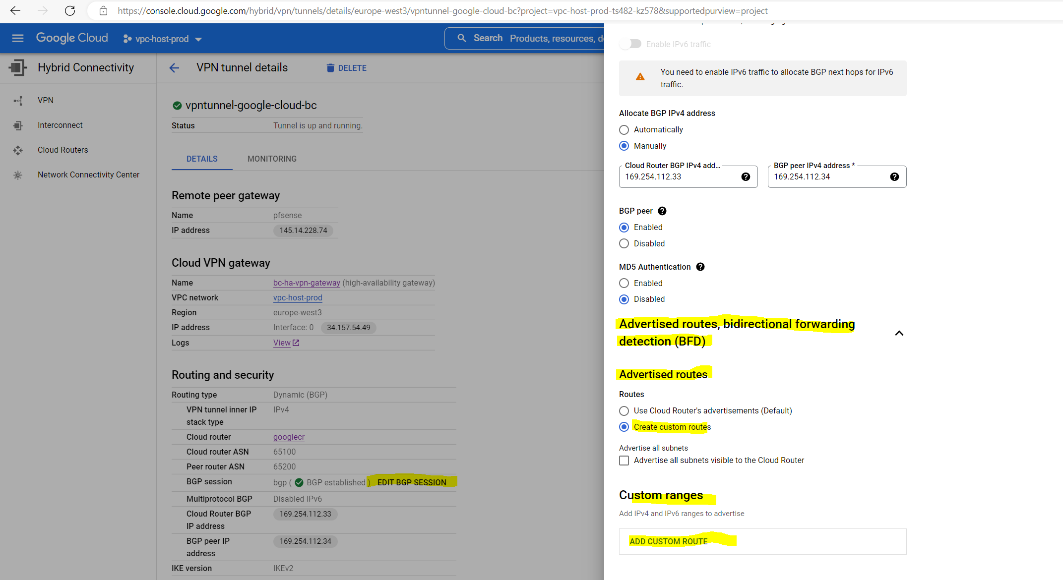
In order to change which routes you want to advertise to on-premise, you can open the tunnel details by clicking on the cloud vpn tunnel.
Then in the tunnel details pane click on Edit BGP Session and select below Create custom routes to add the ip ranges you want to advertise.
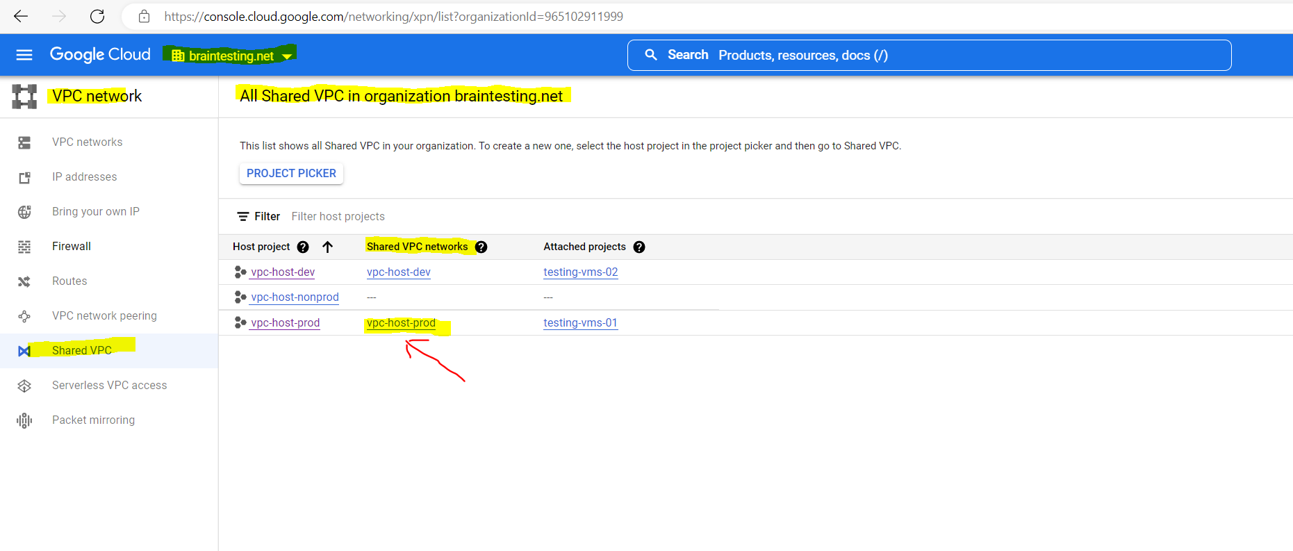
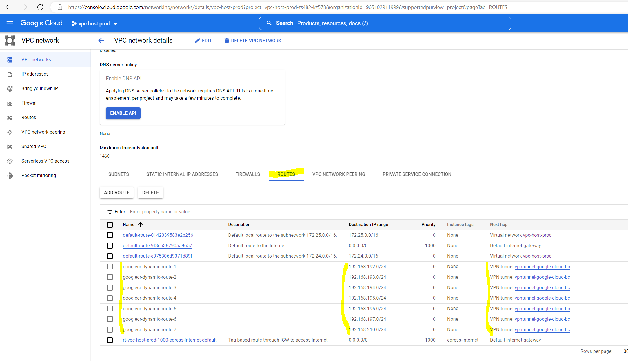
To see the advertised routes from on-premise (pfSense) in Google Cloud, you need to go to the VPC network you where using to deploy (connect) the VPN gateway to.
I was using my production Shared VPC network as you can see below during the creation of the HA VPN gateway.
vpc-host-prod is the production Shared VPC network
So I will have go to the Shared VPC networks in my organization and click on vpc-host-prod.
Then select the Routes tab
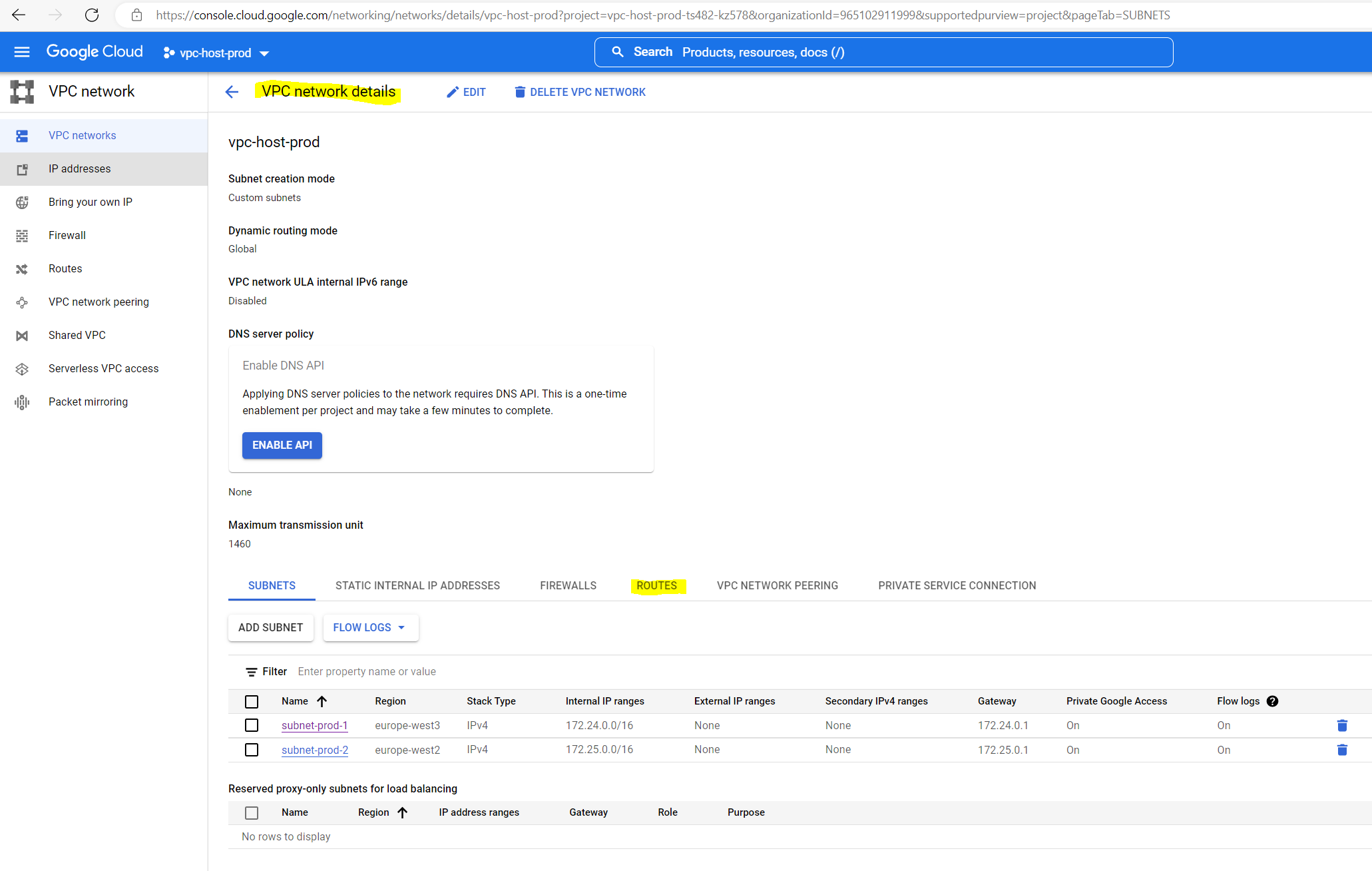
Here you can see all 7 advertised routes (googlecr-dynamic-route1-7) from on-premise (pfSense) where the next hop is already pointed to the VPN tunnel we created.
Adding a second Tunnel for high availability
As mentioned previously I was first just creating a single VPN tunnel for testing purpose. Now I will show how you can add a second tunnel to your existing configuration.
Under Networking –> Hybrid Connectivity –> VPN I will see my configured tunnels and here I can create a second VPN tunnel.
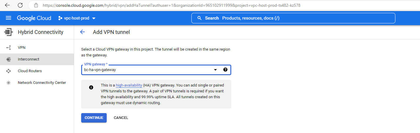
I want to add a second tunnel to my existing VPN gateway, therefore I will select my existing VPN gateway here.

Here I will select my on-premise peer gateway (pfSense).

As I want to add a second tunnel to my existing one, I have to select another time to Create a single VPN tunnel below.

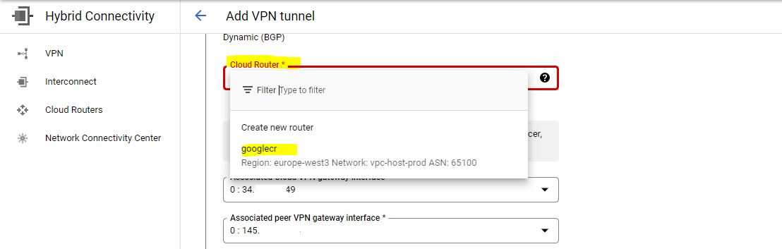
Select your existing cloud router.
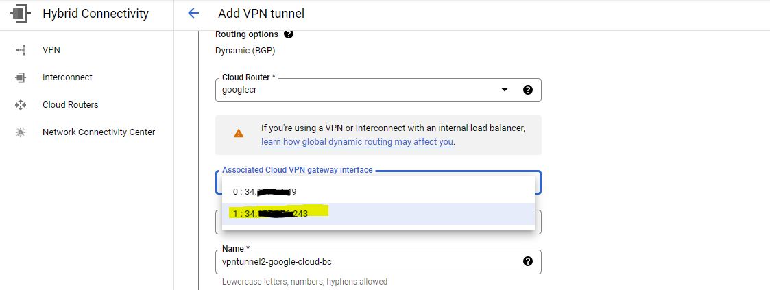
Below choose one of the VPN gateway interfaces, as I was using the first one with id:0 for the first tunnel, now I have to select the second one with id:1 for my second tunnel.
In my on-premise network I will still using the same pfSense appliance for the second tunnel and therefore I will select the same peer VPN gateway interface as for the first tunnel.
For high availability of course a second peer VPN gateway in on-premise would be the better choice to connect with the second tunnel from the cloud VPN gateway.
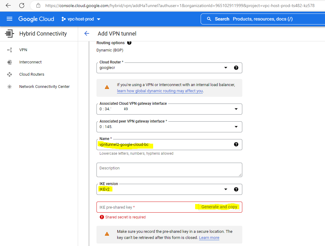
We also need to create a new IKE pre-shared key for the second tunnel.
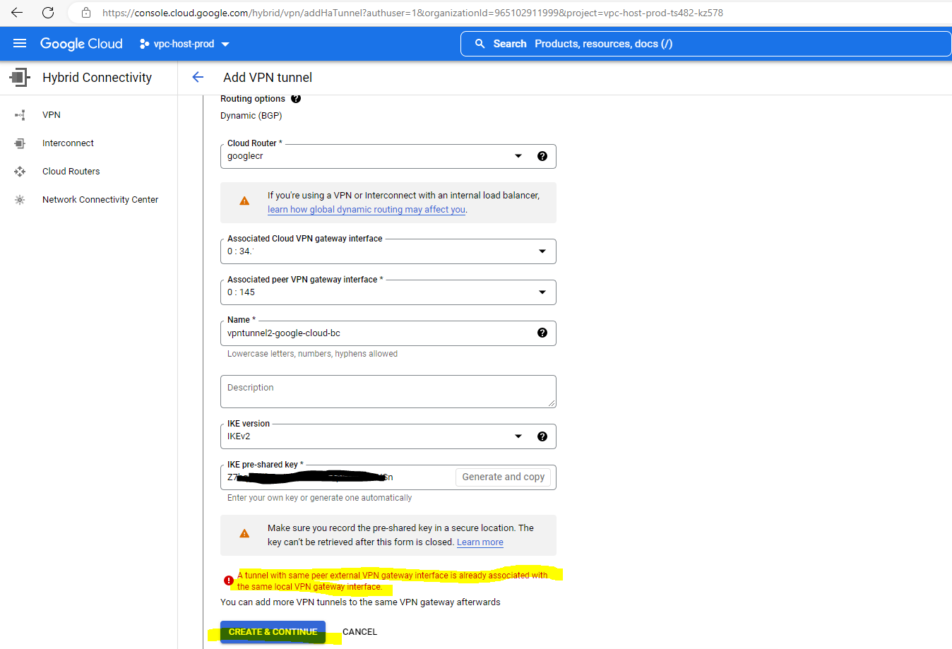
Above you can see the error message that a tunnel had already assigned the external local VPN gateway interface. The first interface with the id:0 is already in use from the first tunnel, so I have to change the interface to use the second one with id:1 as shown below.
To finish the creation of the second tunnel click on Create and Continue.
So far of course the connection is not established as we first also need to configure the second tunnel on our on-premise peer gateway (pfSense).

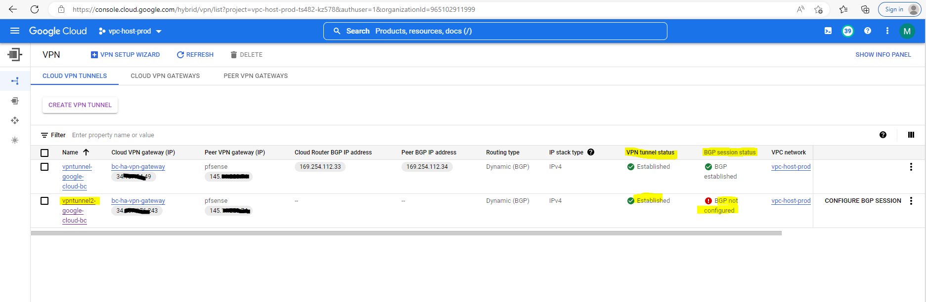
As far as the second tunnel in pfSense is configured, the tunnel with Google will be established as shown below. The BGP session state of course is so far not established as we first also need to configure BGP for the second tunnel at Google site and in on-premise we further need to add a second BGP neighbor in pfSense.
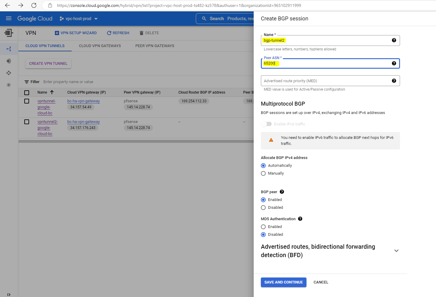
To configure BGP on the Google cloud router click below on Configure BGP session.
We also need to enter a name for the BGP session of the second tunnel and the peer ASN number from our on-premise gateway (pfSense) which will be of course the same as before for the first tunnel.
After configuring the BGP session at Google site, the BGP session will be in state Waiting for peer as we finally also need to configure the BGP session on our on-premise gateway for the second tunnel.
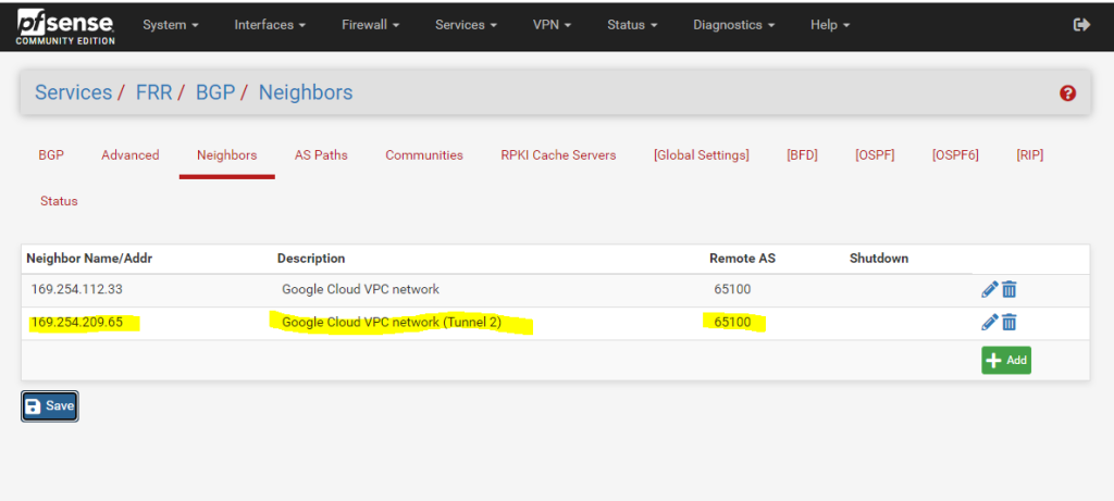
In pfSense we need to add a second BGP neighbor for the second tunnel.
Note !!!
You will also see below the IP addresses for the transit network for the second tunnel you need to configure in pfSense.

In pfSense I need to add a second Phase 1 and Phase 2 for the second tunnel.
I will not show the set up in pfSense for the second tunnel as it is the same as for the first tunnel and you just need to change the IP addresses from the transit network and phase 2 and further the remote IP from the second VPN gateway interface of the Google cloud router.
The IP addresses for the transit network you will see as shown above in the screenshot for the second tunnel.
Finally my configuration on pfSense including the second tunnel will looks like this.

The configuration for BGP to add a second BGB neighbor you will find as already mentioned in my following post.
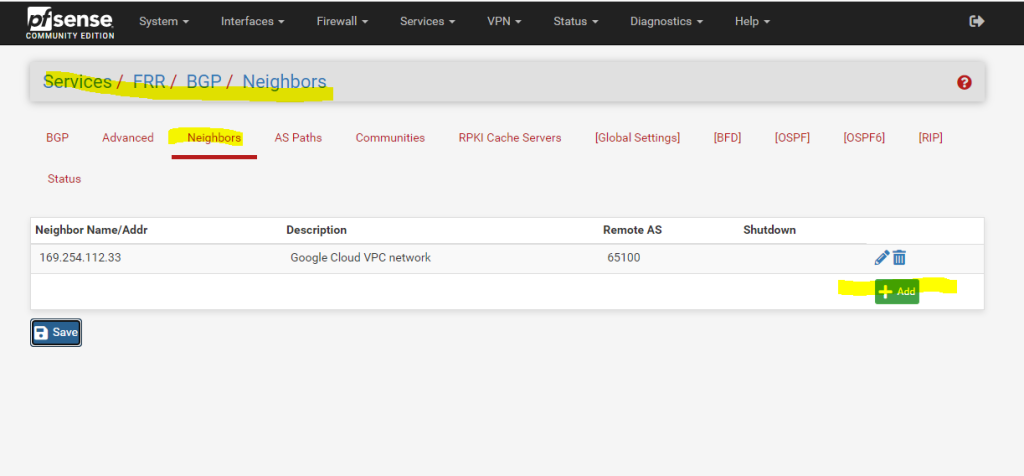
So finally after adding the BGP neighbor also the BGP session state is established and the warning message about HA VPN tunnels are not properly configured for a 99.99% SLA is now gone.
Configuration before adding the second tunnel and showing the warning message
Testing the Tunnel
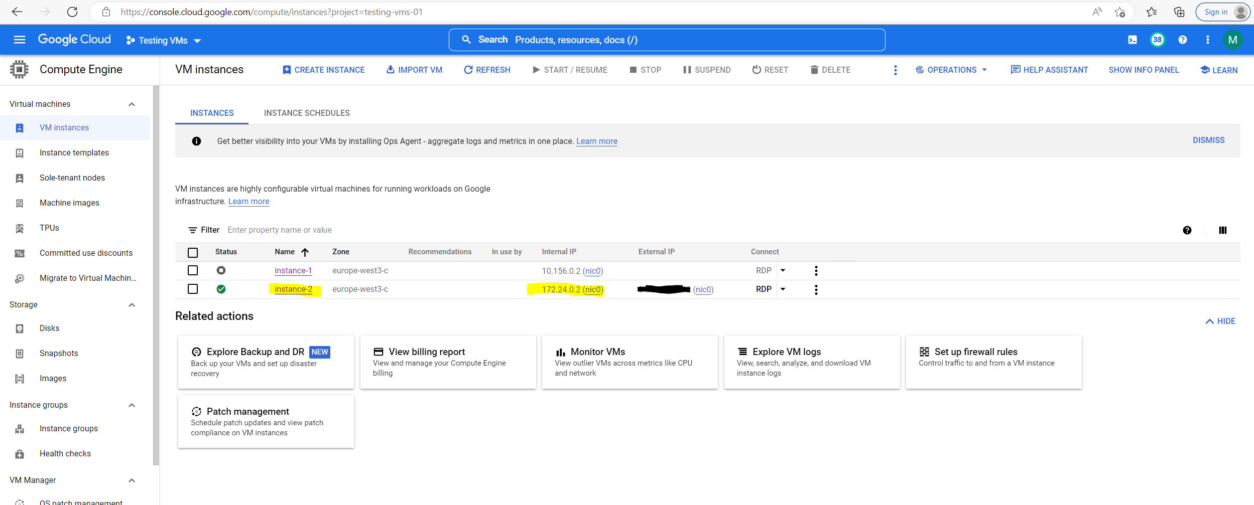
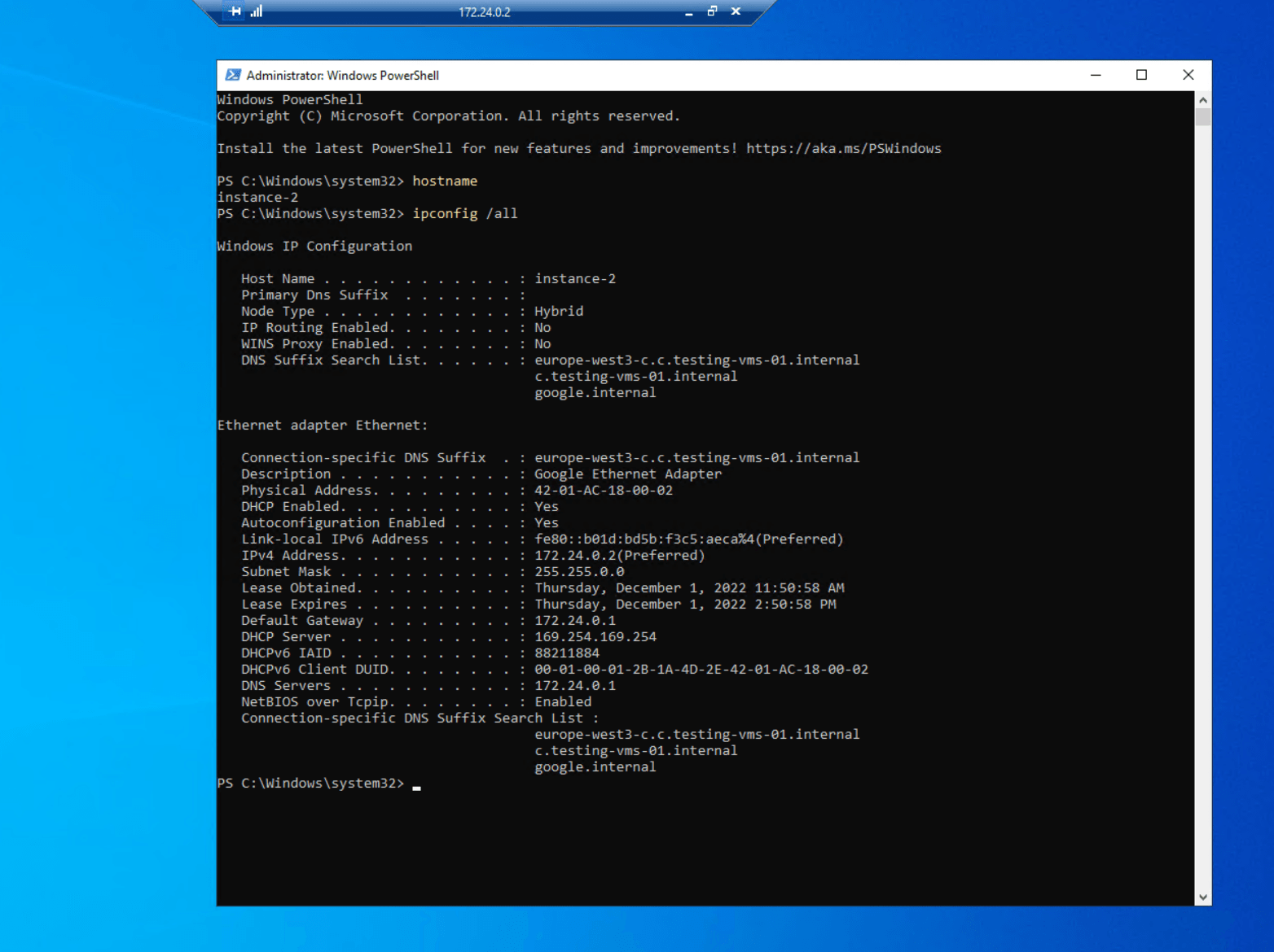
In order to test the tunnel, I will create a new VM instance inside my project Testing VMs. Therefore I first need to attach this project to the Shared VPN network (production) hosted itself in the host project vpc-host-prod, so that an IP address from that network can be assigned to my VM.
Here you can see the internal private IP address 172.24.0.2 from my testing vm instance-2.
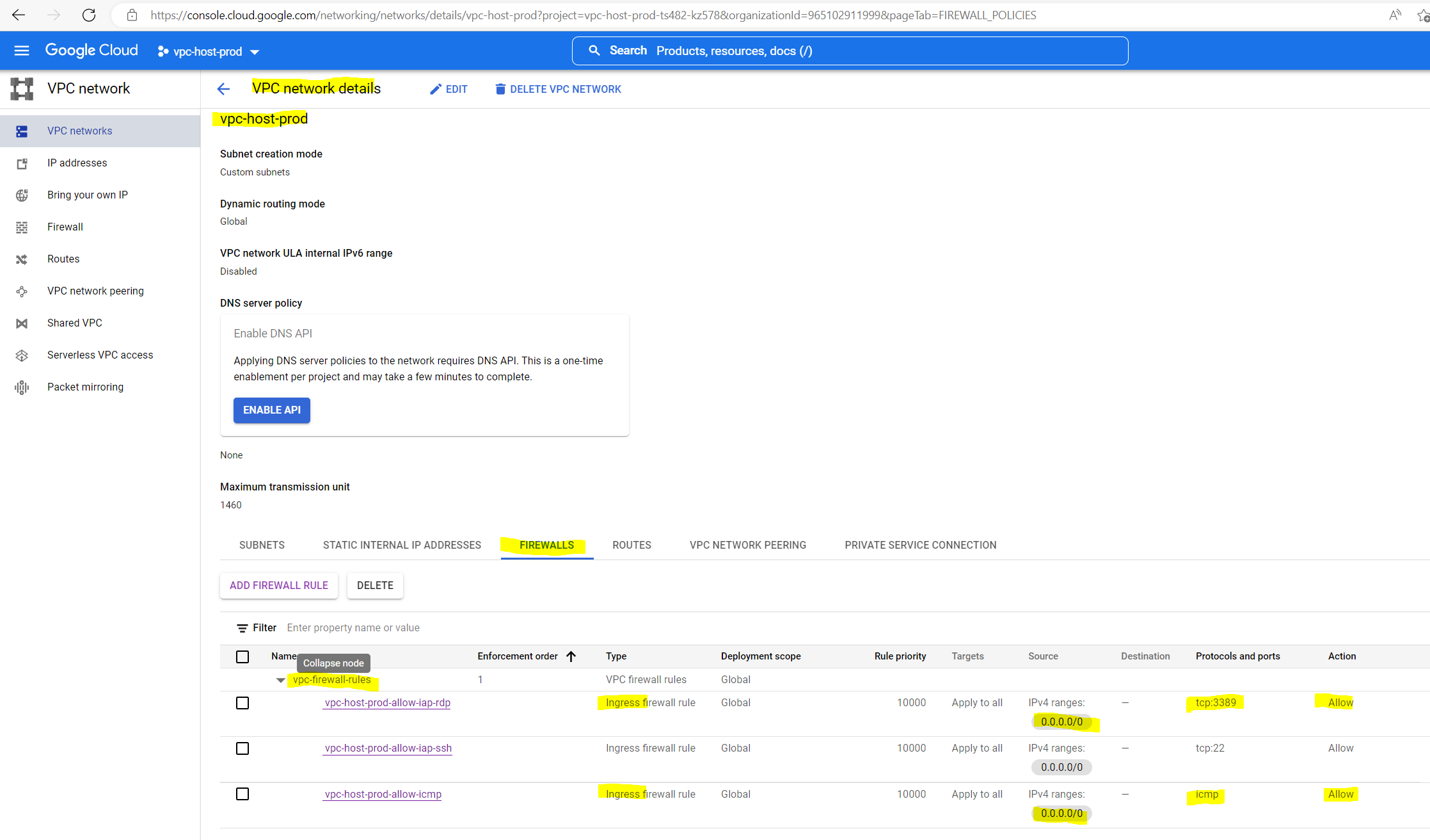
In order that we can connect to the VM by using RDP from our on-premise network, we first need to allow RDP TCP 3389 traffic inbound to the associated VPC network.
For testing purpose I will allow inbound (ingress) traffic from any source IP address.
Further I will allow ICMP traffic like Echo request and reply messages inbound from any source.
So finally I was able to connect from my on-premise network by using RDP to my VM in the Google Cloud VPC network and using the internal private IP address from the VM.
Set up IPSec route based S2S VPN for an AWS VPC and Azure VNet
If you are also interested about how to set up the same for Amazon’s AWS VPC, you can read my following post.
For an Azure VNet you can read my following posts.
Links
Cloud VPN overview
https://cloud.google.com/network-connectivity/docs/vpn/concepts/overviewCreate a Classic VPN using dynamic routing
https://cloud.google.com/network-connectivity/docs/vpn/how-to/creating-vpn-dynamic-routesChoosing a Network Connectivity product
https://cloud.google.com/network-connectivity/docs/how-to/choose-productCreate an HA VPN gateway to a peer VPN gateway
https://cloud.google.com/network-connectivity/docs/vpn/how-to/creating-ha-vpnDynamic (BGP) routing
https://cloud.google.com/network-connectivity/docs/vpn/concepts/choosing-networks-routing#dynamic-routing