IPSec dynamic route-based S2S VPN Tunnel between pfSense and an Azure VNet
Today I want to go over the steps to establish a Site-to-Site IPSec route-based vpn tunnel between an onPremise network and a virtual network (VNet) in Azure. For the onPremise site I will use a pfSense appliance as VPN device.
- Create a VNet and Subnets
- Create Virtual Machine optional to do some testing later
- Create a Virtual Network Gateway
- Create a Local Network Gateway
- Configure the IPSec Tunnel and BGP on pfSense
- Troubleshooting
- Troubleshooting IPsec VPNs
- Duplicate IPsec SA Entries
- Set up IPSec route based S2S VPN for AWS and Google's Cloud VPC
Create a VNet and Subnets
First we have to create a virtual network in Azure which we will be later connected over a S2S vpn tunnel with our onPremise network.
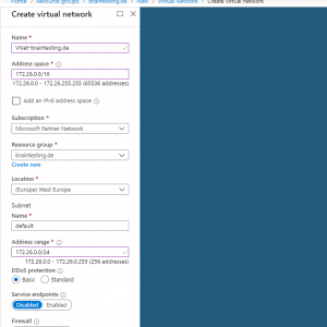
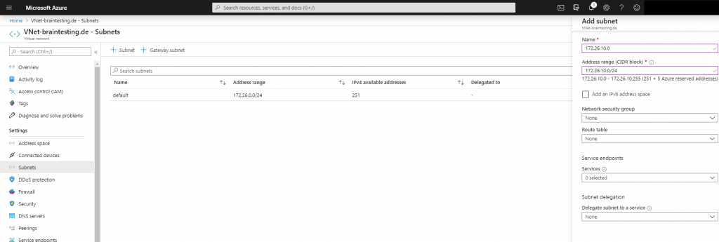
Inside this VNet we create an subnet in which our virutal machines will reside and therefore be connected over the vpn tunnel with our onPremise network.
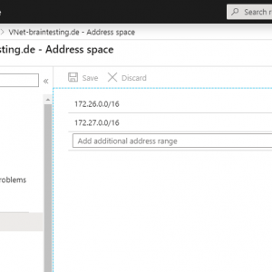
As we create a dynamic route based S2S vpn tunnel, I will add a further address space to the VNet. I don’t really need this but we can see later how these several address spaces will be automatically advertised by the BGP protocol and so we do not have to create hidden policy-based forwarding rules with several phase 2.
As mentioned we do not need to add an IKEv2 phase 2 for each subnet which should be tunneled over the vpn connection, instead we only need one phase 2 for the transit network, over this all subnets will be routed through the tunnel.
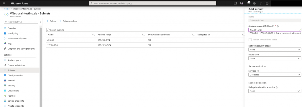
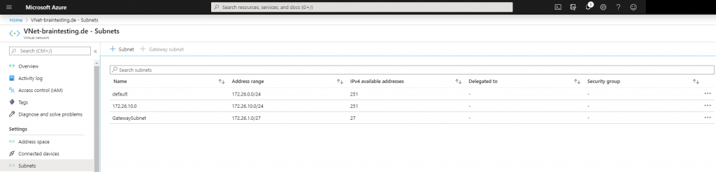
Next we have to add a gateway subnet to the VNet, in this subnet resides the ip addresses of the virtual network gateway which we create later. The name of this subnet must be GatewaySubnet and connot be changed. Further you should not place any virtual machines or other services in this subnet.
For this subnet we must use a minimum of a /29 subnet, Microsoft recommends to calculate a reserve and better use a /27 subnet.
Create Virtual Machine optional to do some testing later
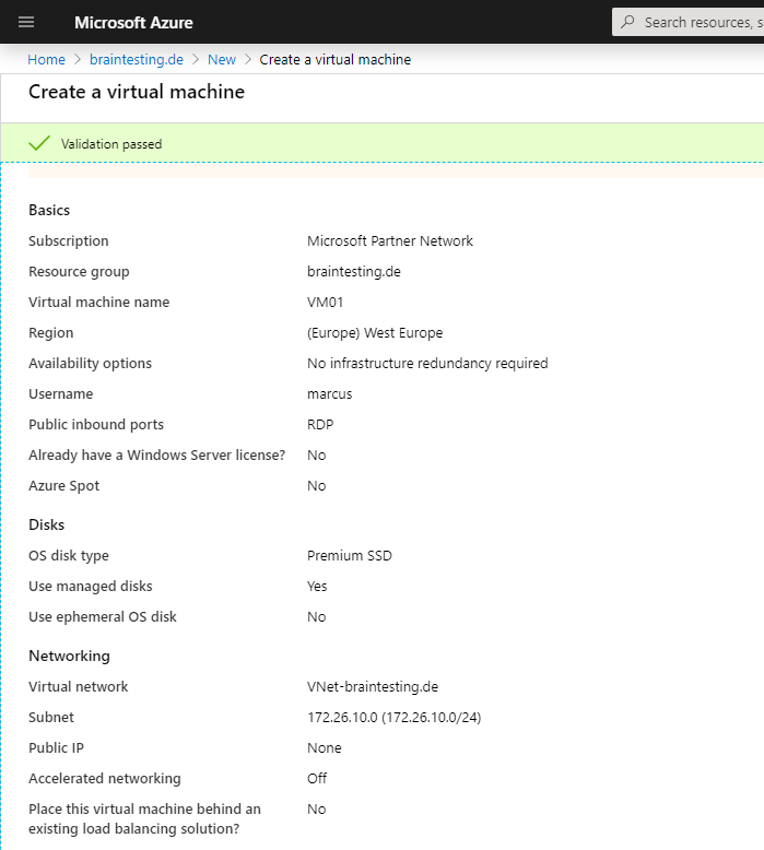
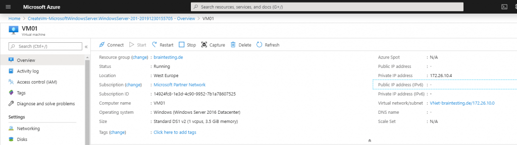
Now we create a virtual machine so that we later can test the vpn tunnel with it. If we create the vm in the same resource group as the VNet, in this case braintesting.de, then the vm will be automatically given an ip address from our previous created VNet and subnet 172.26.10.0/24.
We do not add a network security group to the vm so that we later can easily test different protocols over the vpn tunnel and do not have to configure allow rules. Therefore the vm becomes no public ip address and we only access the vm over the vpn tunnel.
Create a Virtual Network Gateway
To connect our VNet with the onPremise network we need to create a Virtual Network Gateway in Azure.
The Virtual Network Gateway consists of two or more virtual machines which will be created in our previously created GatewaySubnet. These virtual machines provides routing tables and services for the gateway.
https://docs.microsoft.com/en-us/azure/vpn-gateway/vpn-gateway-about-vpngateways
What is VPN Gateway?
A VPN gateway is a specific type of virtual network gateway that is used to send encrypted traffic between an Azure virtual network and an on-premises location over the public Internet. You can also use a VPN gateway to send encrypted traffic between Azure virtual networks over the Microsoft network. Each virtual network can have only one VPN gateway. However, you can create multiple connections to the same VPN gateway. When you create multiple connections to the same VPN gateway, all VPN tunnels share the available gateway bandwidth.
What is a virtual network gateway?
When you configure a virtual network gateway, you configure a setting that specifies the gateway type. The gateway type determines how the virtual network gateway will be used and the actions that the gateway takes. The gateway type ‘Vpn’ specifies that the type of virtual network gateway created is a ‘VPN gateway’. This distinguishes it from an ExpressRoute gateway, which uses a different gateway type. A virtual network can have two virtual network gateways; one VPN gateway and one ExpressRoute gateway. For more information, see Gateway types.
Creating a virtual network gateway can take up to 45 minutes to complete. When you create a virtual network gateway, gateway VMs are deployed to the gateway subnet and configured with the settings that you specify. After you create a VPN gateway, you can create an IPsec/IKE VPN tunnel connection between that VPN gateway and another VPN gateway (VNet-to-VNet), or create a cross-premises IPsec/IKE VPN tunnel connection between the VPN gateway and an on-premises VPN device (Site-to-Site). You can also create a Point-to-Site VPN connection (VPN over OpenVPN, IKEv2, or SSTP), which lets you connect to your virtual network from a remote location, such as from a conference or from home.
For the Gateway type we use VPNand the VPN type is Route-based.
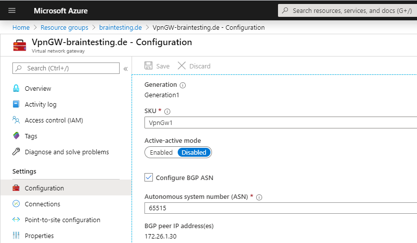
Also we must choose a SKU (Stock keeping Unit | Pricing Tier) for the virtual network gateway, to support route-based vpn we use VpnGw1, below you will find more about the different SKUs.
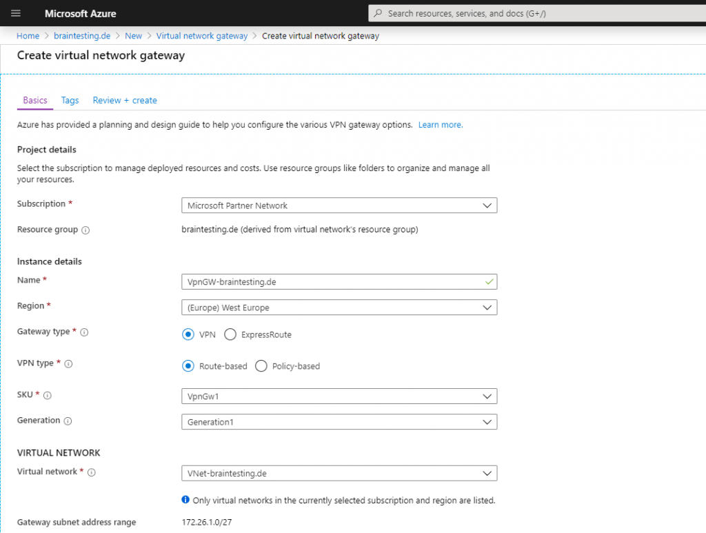
Be aware of what type of SKU (Stock keeping Unit | Pricing Tier) you choose below for the virtual network gateway. By default the Basic SKU is a legacy SKU and has feature limitations like no support for routed-based vpn with BGP.
Working with virtual network gateway SKUs
https://docs.microsoft.com/en-us/azure/vpn-gateway/vpn-gateway-about-skus-legacy
Supported configurations by SKU and VPN type
https://docs.microsoft.com/en-us/azure/vpn-gateway/vpn-gateway-about-skus-legacy#config
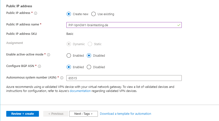
Because we create a Route-based VPN which determines dynamically the routes, we must enable and configure here the BGP protocol. For the Azure site is the private ASN 65515 reserved.
https://en.wikipedia.org/wiki/Autonomous_system_(Internet)
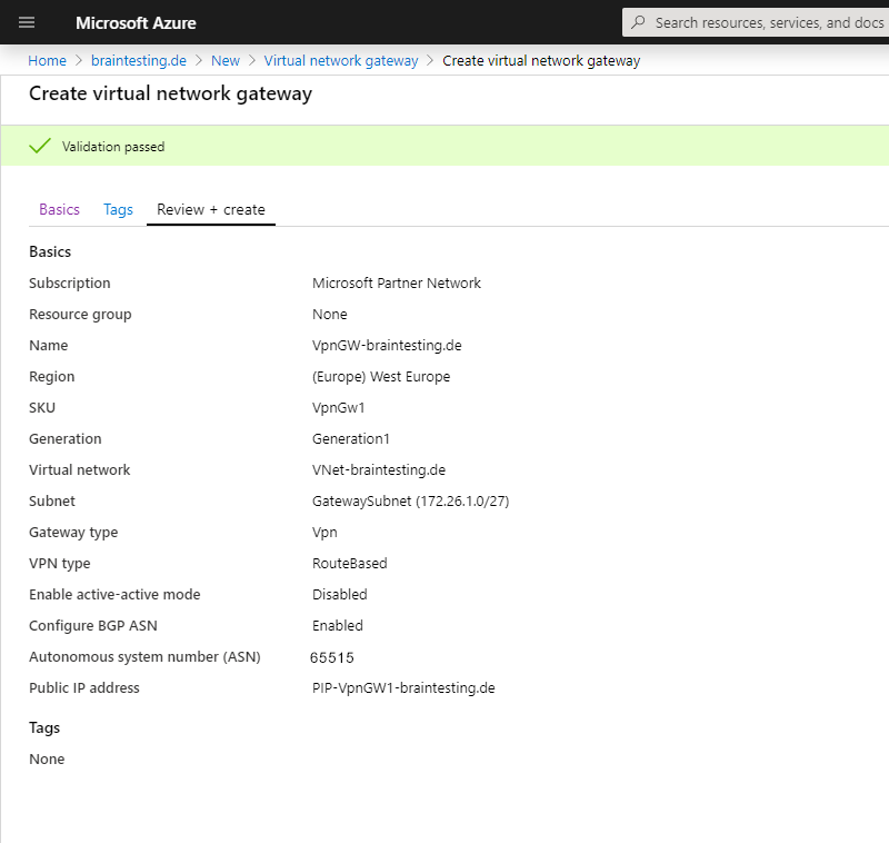
In my case I get a wired error message at validation that the ASN 65515 is reserved for Microsoft and cannot be used ? , after retyping the number 65515 the validation passed, no idea why this happens, must be a bug at the moment.
The deployment of the Virtual Network Gateway can take up to 45 minutes! So grab a coffee ☕ …
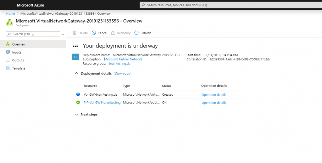
Here you can see the finished Virtual Network Gateway, under Settings – Configuration you can see the BGP peer IP which we need later for the vpn configuration at pfSense.
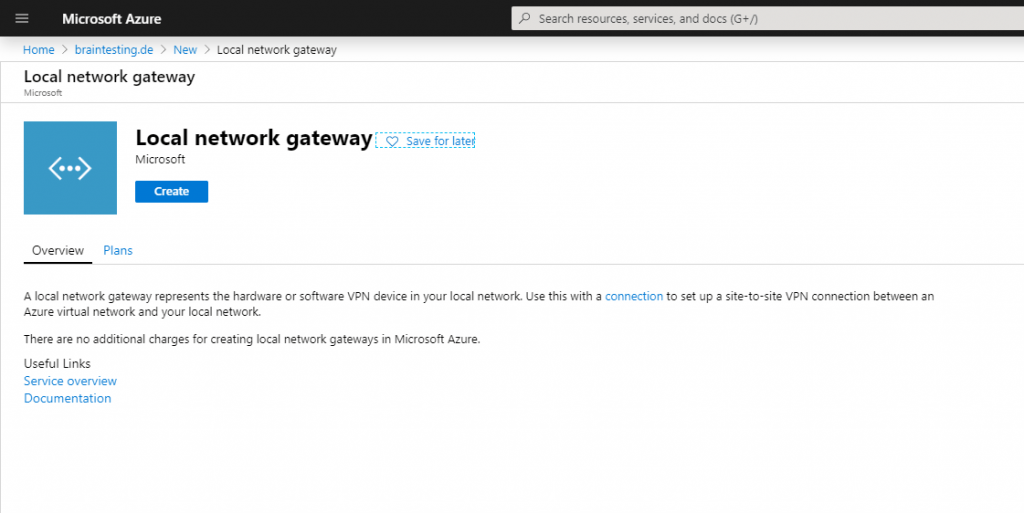
Create a Local Network Gateway
Next we have to create the Local Network Gateway which represents your onPrem VPN Gateway in Azure. It is a specific object in Azure to provide some informations of your onPrem Gateway like IP address and Prem subnets you want to route over this Tunnel.
Each virtual network can have only one virtual network gateway, but one virtual network gateway can be used to configure multiple VPN connections.
Add a Site-to-Site connection to a VNet with an existing VPN gateway connection
https://docs.microsoft.com/en-us/azure/vpn-gateway/vpn-gateway-howto-multi-site-to-site-resource-manager-portal#before
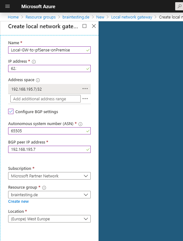
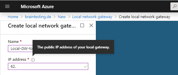
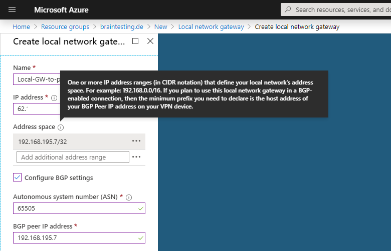
Under IP address you must use the public IP address from pfSense on the onPremise network. In my case 62….
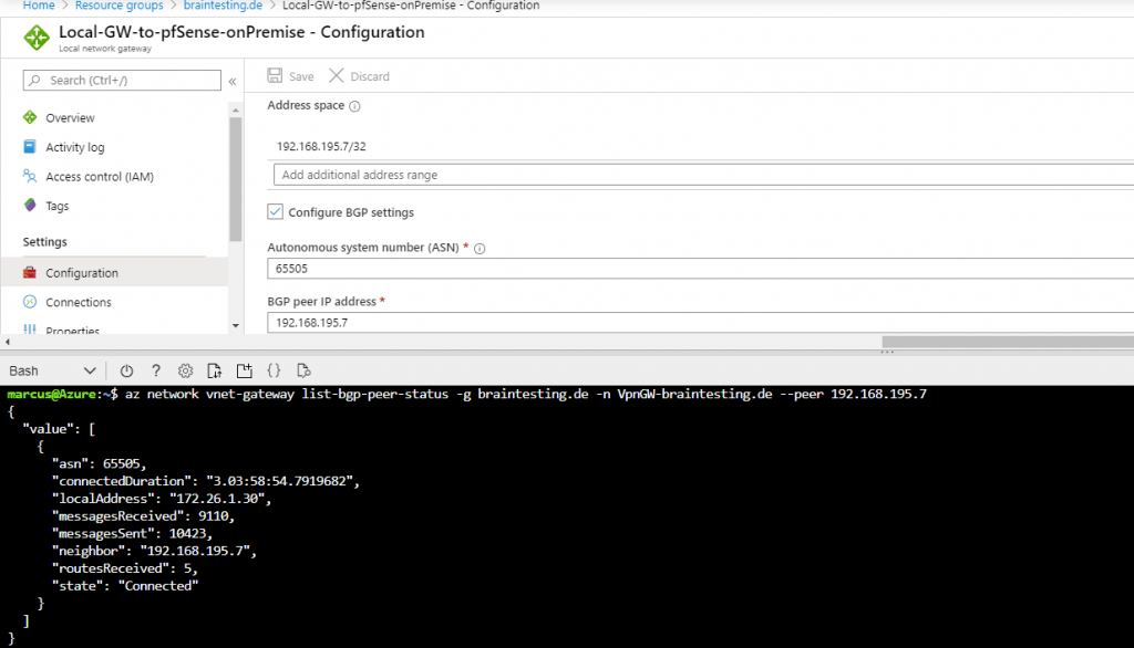
Under Address space we type the IP from our BGP peer in pfSense. This is the IP from the internal interface from pfSense.
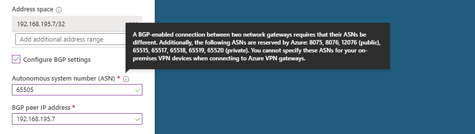
We also need to type this IP in the BGP peer IP address field below and a private ASN number for our on-Premise BGP peer, I will use here 65505 which later also have to be configured on pfSense.
You can use here a number from the reserved private use range which is from 64512 – 65534, besides 65515 which is reserved for the Azure VNets as mentioned above.
More about Autonomous system (Internet)
https://en.wikipedia.org/wiki/Autonomous_system_(Internet)
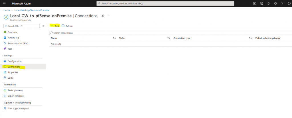
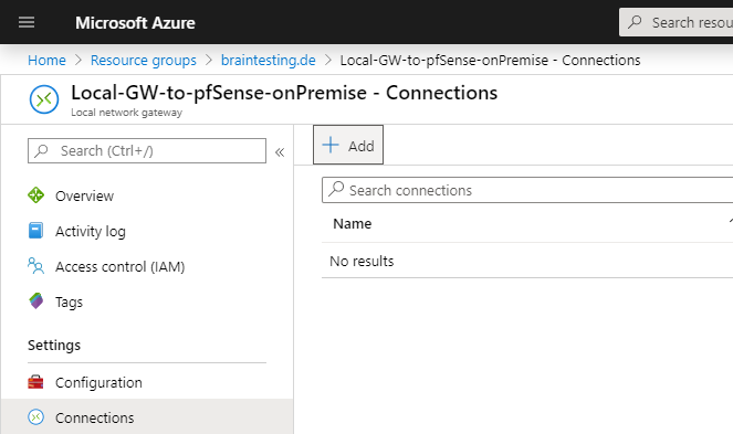
Now we have to add a new connection to our Local network gateway object, which represents the actual tunnel to our onPrem Gateway.
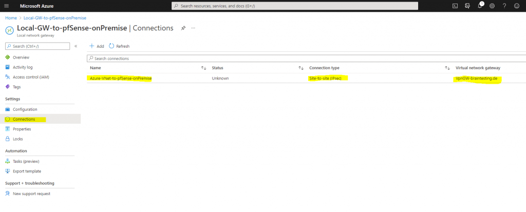
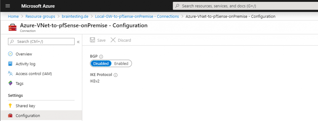
If we click on the connection, we can adjust the configuration from the tunnel.
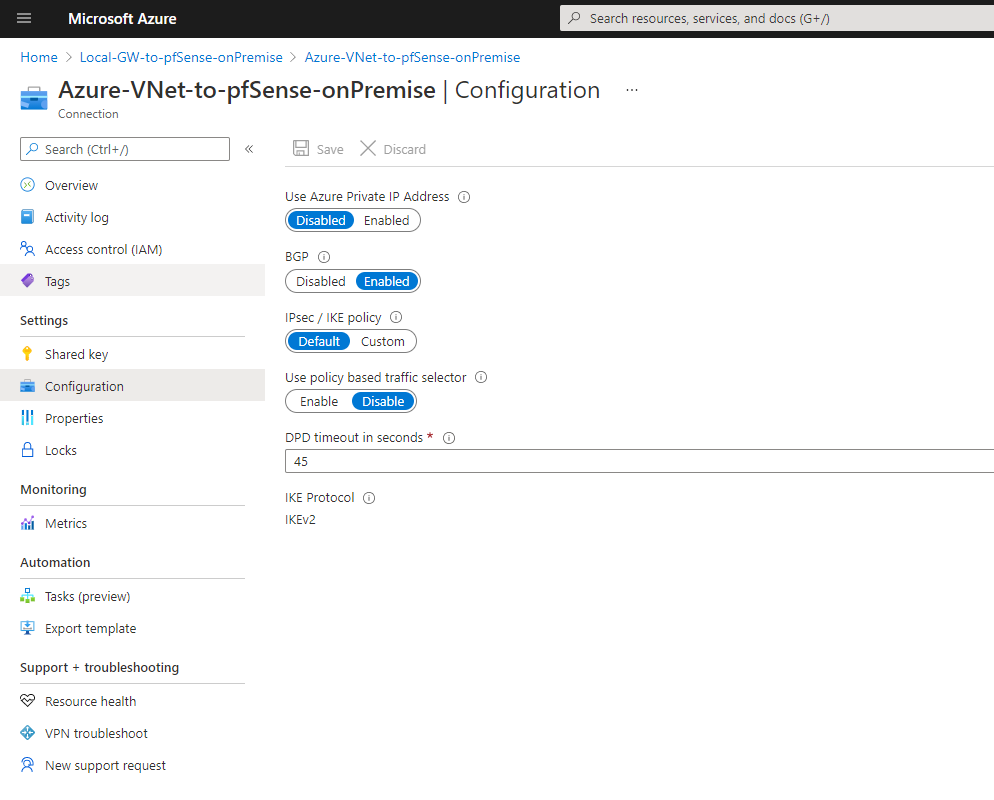
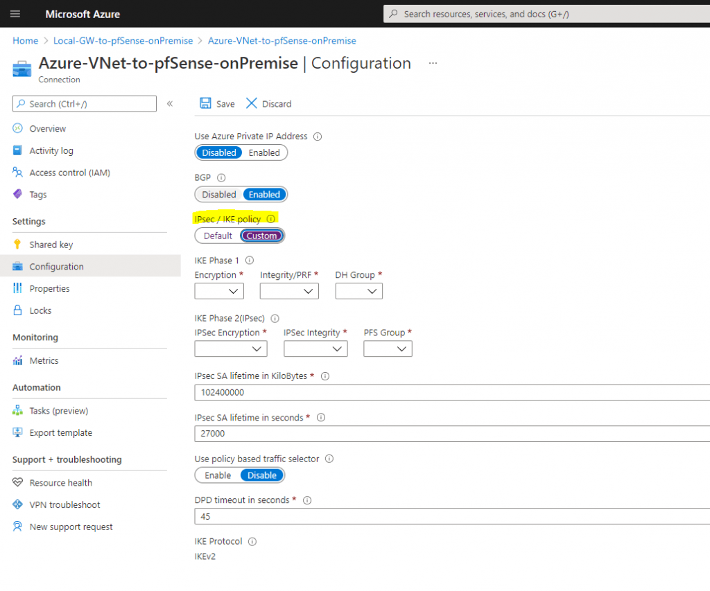
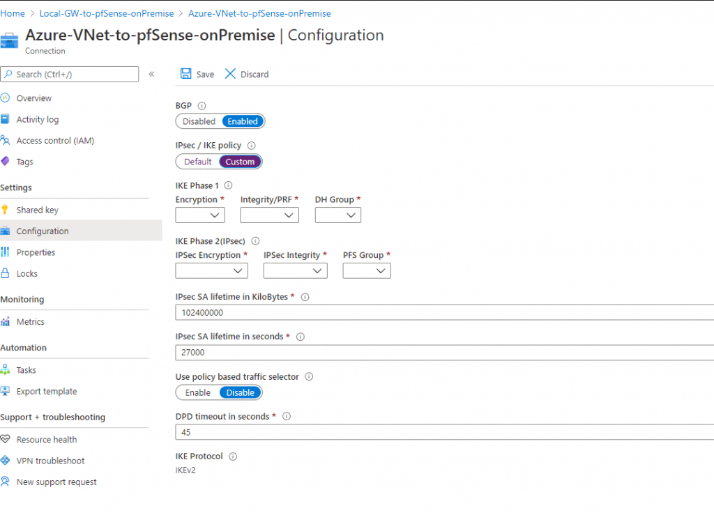
The default IPSec / IKE policy settings for the SKU VpgGw1 you can see further down, so can adjust your onPrem Gateway (pfSense) to use the same or you can define your own policy settings if you switch the button to Custom as follows.
Default Settings
Custom settings
Configure the IPSec Tunnel and BGP on pfSense
In order to configure the last step in Azure, the actual IPSec Connection, we will first create on pfSense in our onPremise network the IPSec tunnel, Border Gateway Protocol and the transit network.
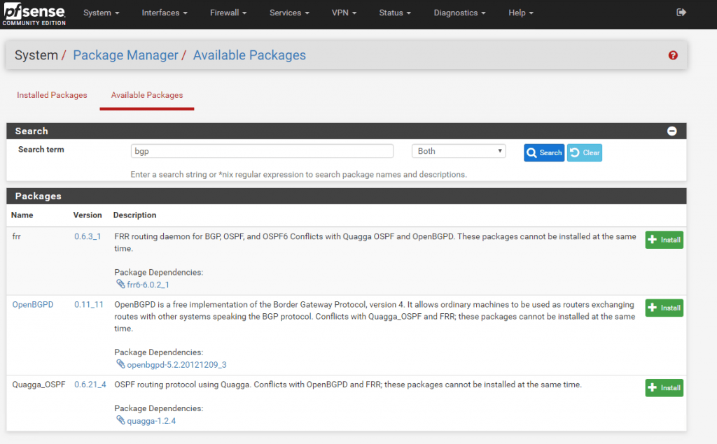
First we will install with the Package Manager the OpenBGPD daemon, which will provide us the BGP Protocol at pfSense.
OpenBGPD is since pfSense version 2.4.5 depricated and since version 2.5.0 no longer available in pfSense!
Therefore you should move to FRR. How to install and configure FRR you will find in my following post.
BGP is advertising the routing informations between the connected peers. So with BGP we do not need to configure manual static routes for the remote site and peer, as they will automatically advertised from them with BGP.
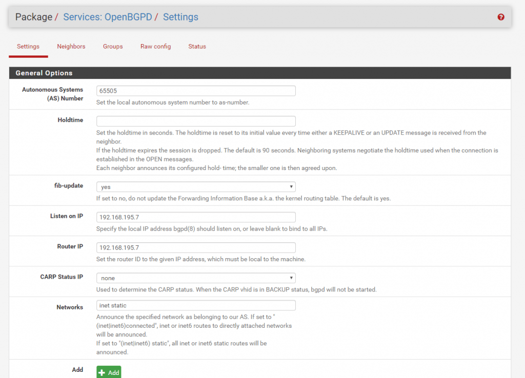
After the installation of OpenBGPD we can configure it under Services – OpenBGPD – Settings.
For the ASN Number I use the private 65505 which we previous set at the Local Network Gateway in Azure. For the Listen and Router IP I use the internal IP from the pfSense Interface.
https://en.wikipedia.org/wiki/Autonomous_system_(Internet)
At Network you can select which networks should be advertised to the VNet in Azure. I used here inet static which advertises the static routes on the pfSense.
Be aware of adding the inet connected to the advertised networks, both networks from the local adapters (WAN/LAN) will be advertised as route to the Azure BGP peer.
In this case, also the complete WAN Subnet in which the adapter resides, will be advertised as route to the Azure BGP peer.
Because of this, all interfaces in this VNet will get this route included in their routing table.
Therefore the VMs would try to reach all public IPs from this Subnet, through the vpn tunnel instead the default gateway for the internet traffic, which would be not desirable and working.
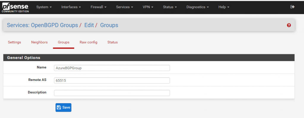
At the Groups tab we set the ASN from the Azure VNet which will be our remote site.
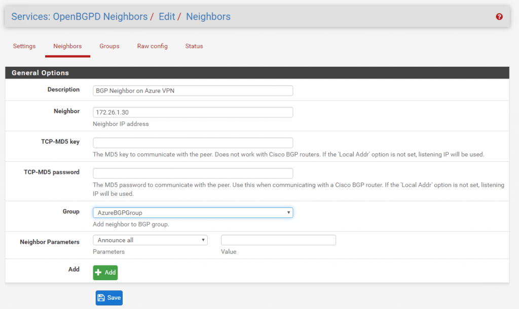
Last for the BGP configuration we must add the BGP Neighbor. Set here the BGP Neighbor IP from the Azure BGP peer. You will find this IP in Azure under the settings from the Virtual Network Gateway and is in my case the 172.16.1.30. Under Groups select the previous created remote ASN Group from Azure.
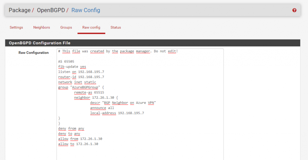
Under Raw Config you can review the complete BGP configuration.
The tab Status we will examine later.
First we have to configure the IPSec tunnel.
To configure the IPSec Tunnel with all the correct IPSec/IKE parameters on the onPrem VPN device in your local network, there are several options available.
For route based VPNs with the following gateway SKUs, you can adjust the IPSec/IKE parameters to meet your requirements of the onPrem Gateway.
- VpnGw1 – 5
- VpnGw1AZ – 5AZ
- Standard and HighPerformance
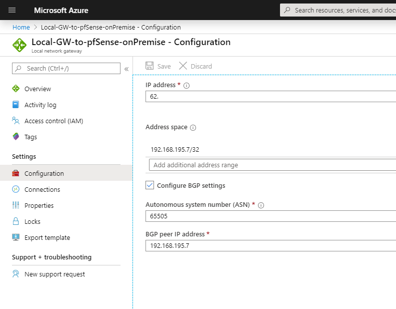
In this case you can adjust the parameter directly at the connection from the local network gateway under Configuration as follows:
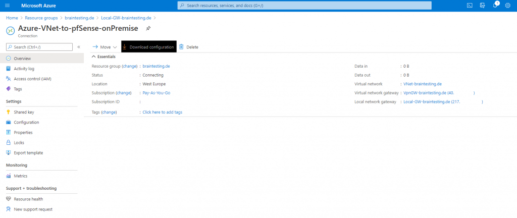
Another option is to download the default azure configuration script from the local network gateway overview page in Azure if your device is supported and a script is available.
To see if for your device a script is available you can check this on https://docs.microsoft.com/en-us/azure/vpn-gateway/vpn-gateway-about-vpn-devices#devicetable
A detailed instruction of how to download and configure the script you will find on https://docs.microsoft.com/en-us/azure/vpn-gateway/vpn-gateway-download-vpndevicescript
For pfSense there is no script available and its also not validated by Microsoft, doesn’t matter 🙂 , it works smoothly with pfSense.
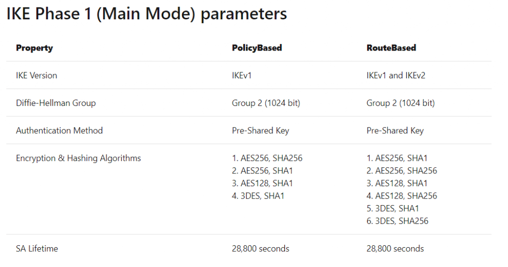
So if we want to use the default Azure IPSec/IKE parameter, we can look on https://docs.microsoft.com/en-us/azure/vpn-gateway/vpn-gateway-about-vpn-devices#ipsec for them.
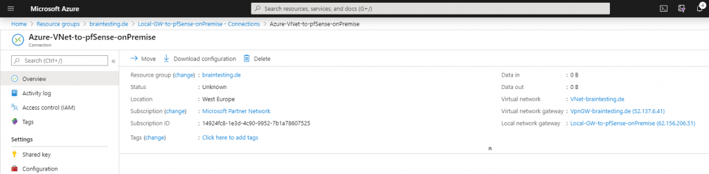
The public IP of the Azure VPN peer you will find on the overview page from the virtual network gateway page or from the local network gateway page under the Settings – Connections menu and there when you click on your S2S connection.
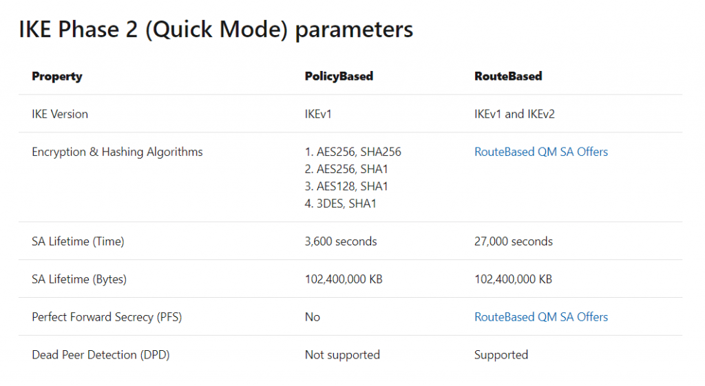
The tables below contain the combinations of algorithms and parameters Azure VPN gateways use in default configuration. For route-based VPN gateways created using the Azure Resource Management deployment model, you can specify a custom policy on each individual connection. Please refer to Configure IPsec/IKE policy for detailed instructions.
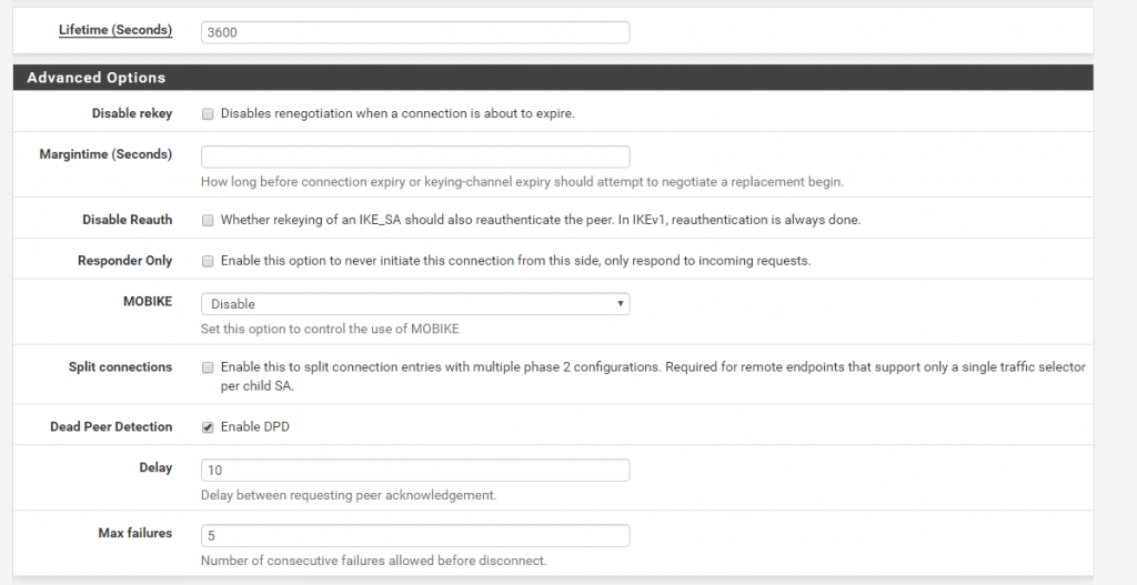
In addition, you must clamp TCP MSS at 1350. Or if your VPN devices do not support MSS clamping, you can alternatively set the MTU on the tunnel interface to 1400 bytes instead.
By default pfSense uses for MSS 1400, you can change it under VPN – IPSec – Advanced Settings. Here you can check Enable Maximum MSS and set it to 1350.
https://docs.netgate.com/pfsense/en/latest/vpn/ipsec/advanced-ipsec-settings.html
In the following tables:
- SA = Security Association
- IKE Phase 1 is also called “Main Mode”
- IKE Phase 2 is also called “Quick Mode”
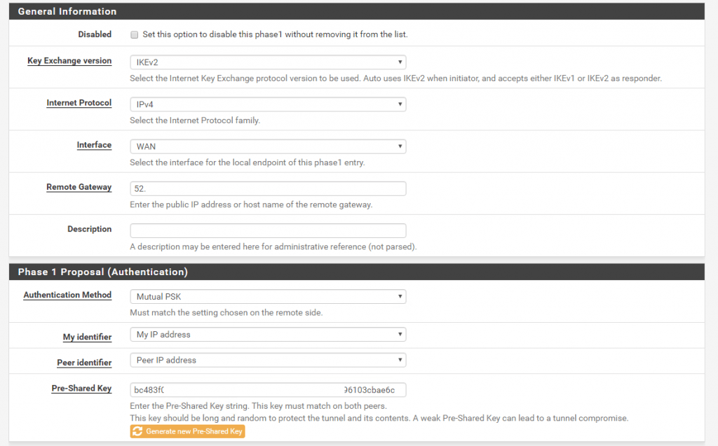
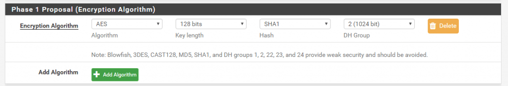
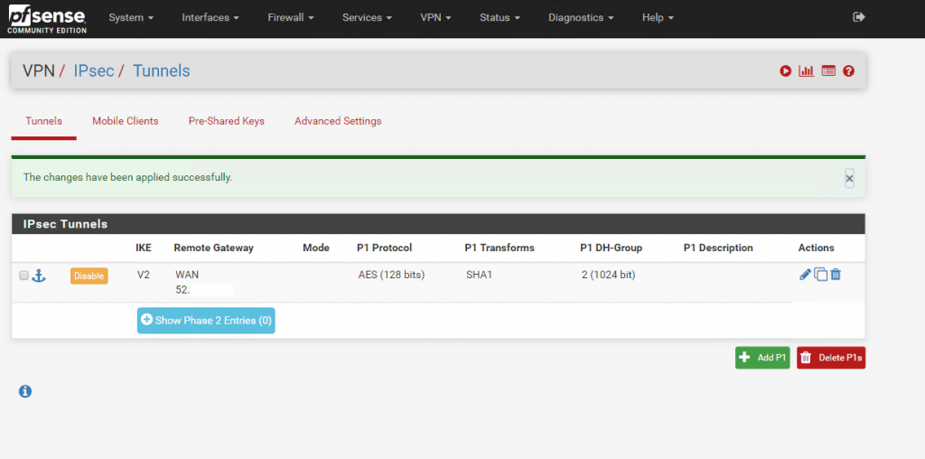
Now select from the menu VPN – IPSec and first create a Phase 1.
Under Key Exchange Version select IKEv2 which will use Azure. As Remote Gatway we use the public IP from the Azure Virtual Network Gateway which you will find in the overview of it.
As Pre-Shared Key (PSK) we will let pfSense create one for us.
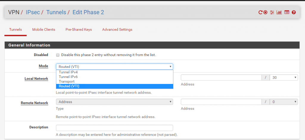
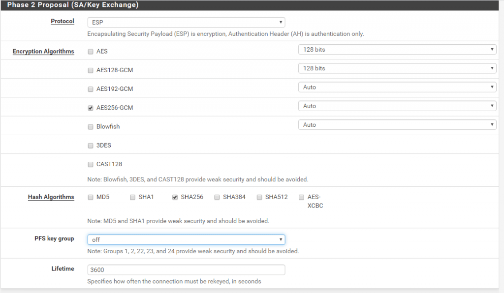
Now as we finished Phase 1 we can create the Phase 2. As we create a Route-based VPN we only needone Phase 2 for the transit network over this our local subnets will be routed to Azure. If we would create a Policy-based VPN, we had to create for each subnet we want to route over the Tunnel, a Phase 2.
Therefore you must select at Phase 2 Mode Routed(VTI). VTI stands for Virtual Tunnel Interface. The default setting is Tunnel IPv4 for Policy-based VPN.
As you select the Routed(VTI) Mode, at pfSense is created a further interface which we will see and assign later.
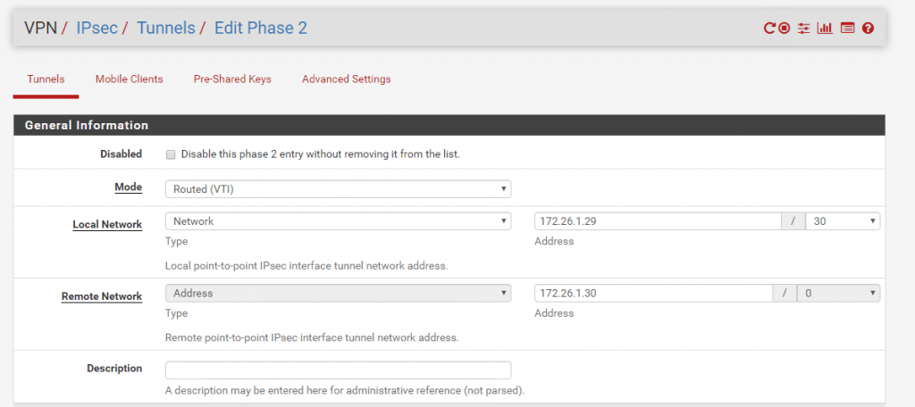
After selecting Routed(VTI) under Local Network, this will be automatically set to Network with a Subnet Mask of /30 which can contain 2 IP addresses. This Network will be our transit network over them the local subnets will be routed to Azure and vice versa.
Because the BGP peer IP from Azure is the 172.26.1.30 and we have a /30 subnet for the transit network wich contains two ip addresses, we must set at pfSense for the Local Network the IP 172.26.1.29/30 and under Remote Network the BGP peer IP from Azure with 172.26.1.30.
After this we had created the transit network wich will be represented through the Phase 2 and will be used to route our local subnets through this tunnel.
As we finished the creation of the IPSec tunnel in pfSense we now have to create it also in Azure.
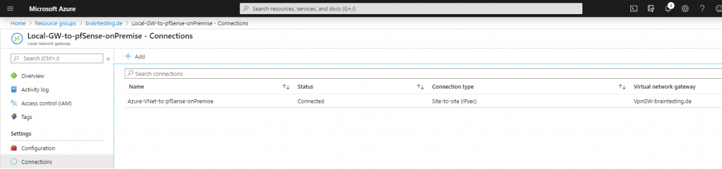
Therefore we go to the Azure Portal and the Local Network Gateway. Under Settings select Connections.
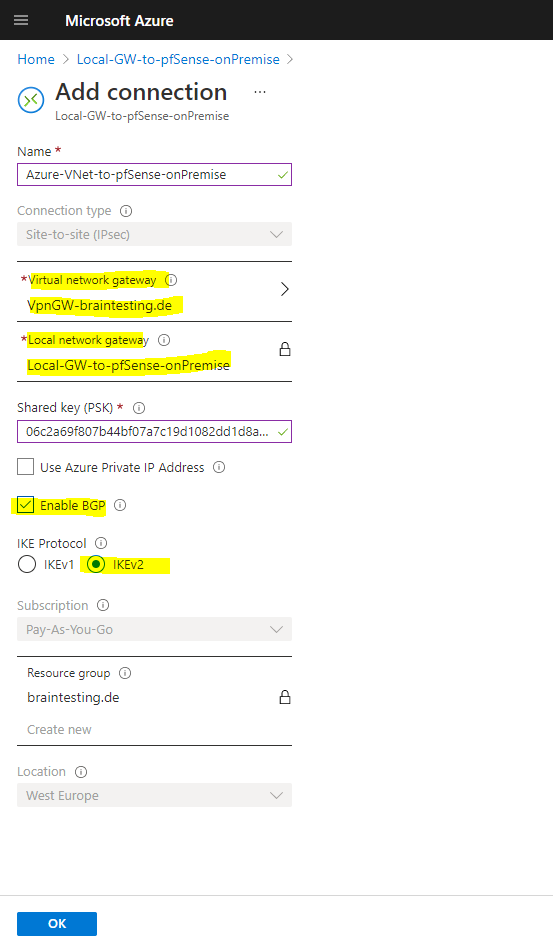
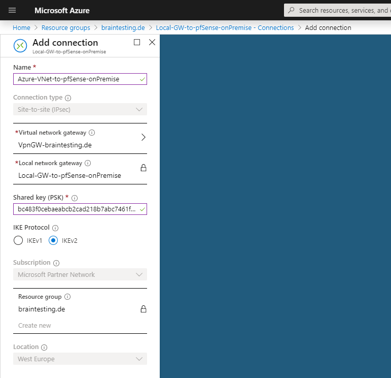
Under Virtual Network Gateway we select the previous created VpnGW-braintesting.de and under Shared key (PSK) we copy and paste the PSK which was generated from pfSense.
After selecting the connection, we can go to the overview and download the configuration from the IPSec tunnel. Here you can see the used parameters and settings for the Phase 1 and Phase 2 which we must use in pfSense also.
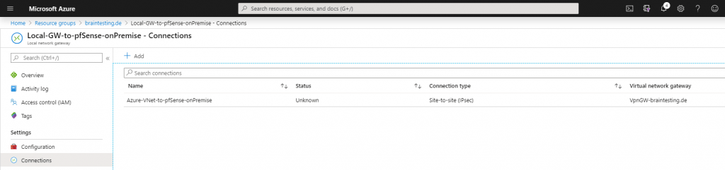
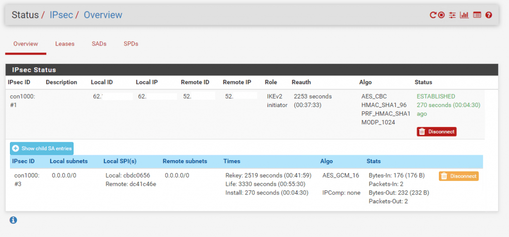
In pfSense under Status – IPSec, we see that the VPN tunnel is successfully established. In the Azure Portal it can last some minutes till you can see the status connected.
A few minutes later …
That routing in pfSense finally works over the IPSec tunnel, we have to assign the IPSec Interface (VTI) which was automatically created after set the Tunnel Mode to Routed(VTI) in the Phase 2 settings.
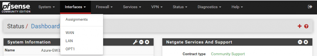
Therefore go to the menu Interfaces – Assignments and add the ipsec Interface.
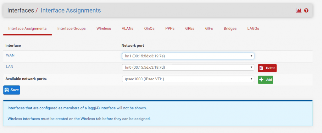
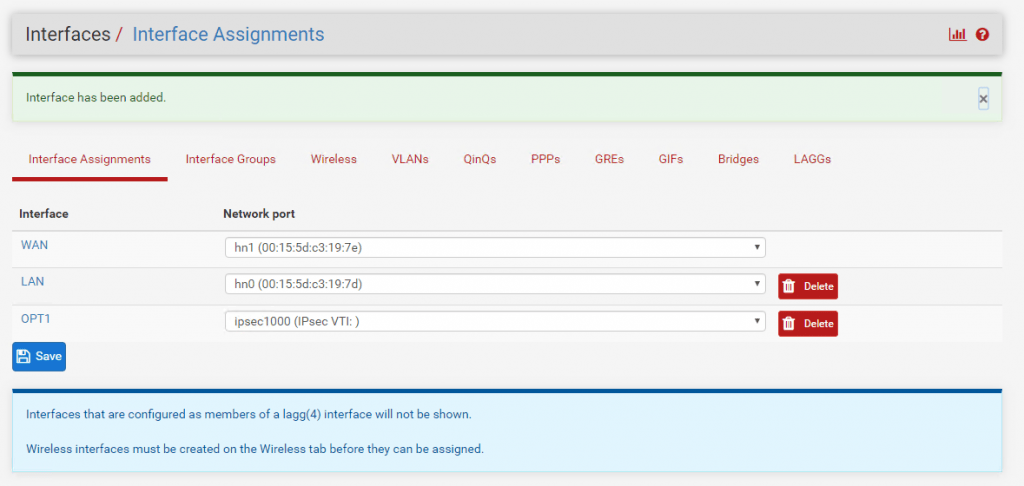
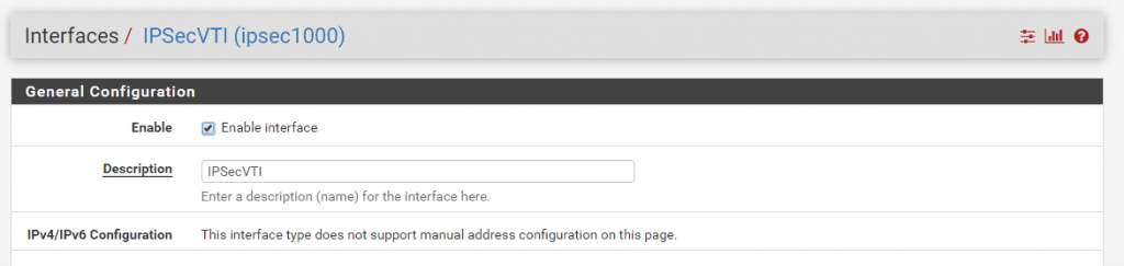
After the assignment you will find this interface with the name OPT1. I changed the name to IPSecVTI for a better understanding.
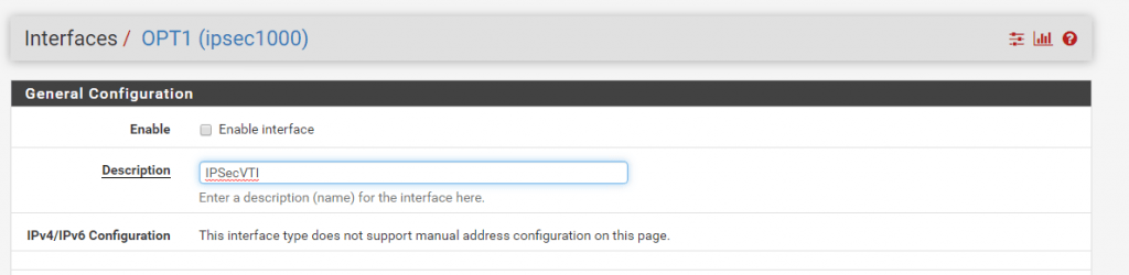
Per default the interface is not enabled, so don’t forget to enable it!
As you can read, we cannot set manual an IP Configuration. The interface will get automatically an IP from the previous created transit network. This IP will represent the gateway to reach our Azure VNet.
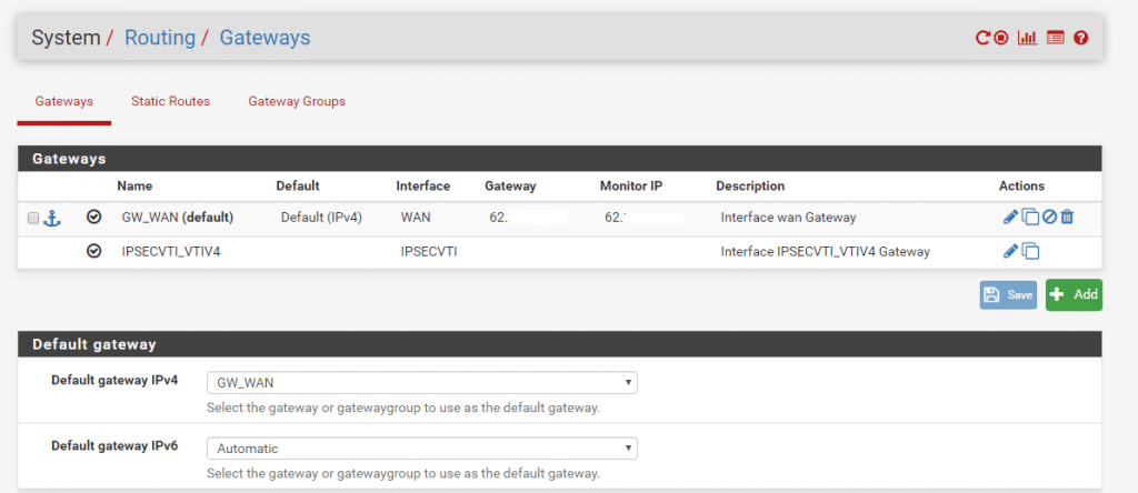
Under System – Routing the Interface is automatically added as Gateway.
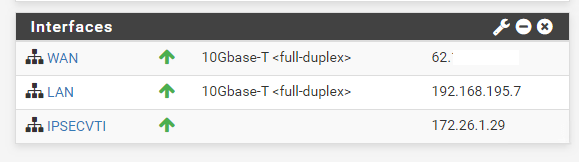
On the Dashboard of pfSense we can see under Interfaces the IPSec Interface and his IP.
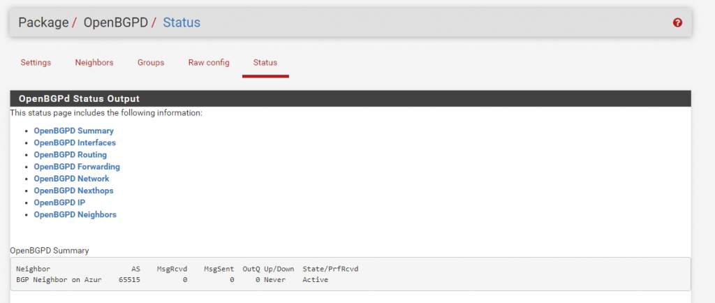
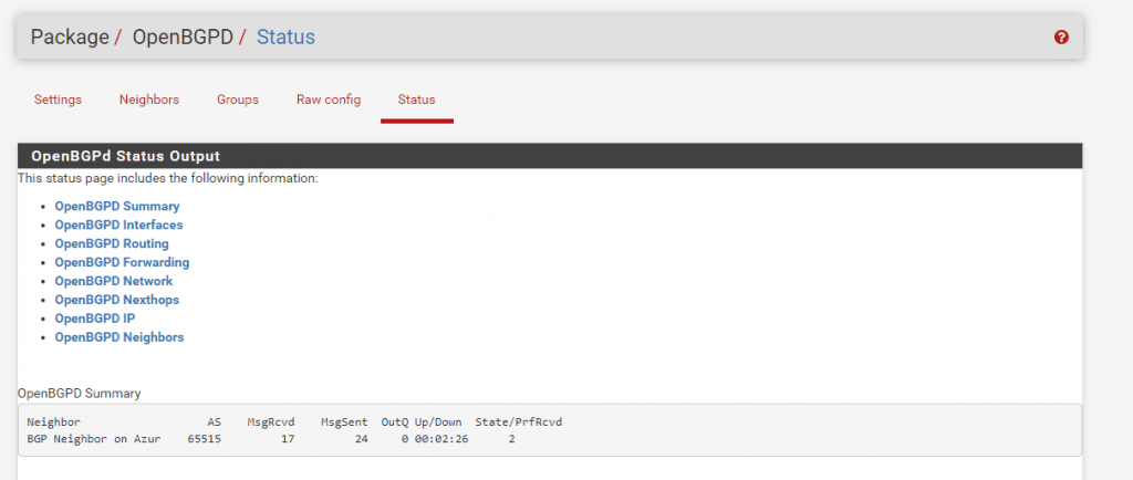
Now we will take a look at the previous mentioned point in the menu under Services – OpenBGPD – Status. Here we can check if the BGP protocol works and if both peers pfSense and Azure exchange his routing tables with the subnets.
As we can see there is no active connection to the BGP peer in Azure.
In my case in Azure the BGP was disabled at the Local Network Gateway.
So after enabled the BGP in Azure and several minutes, the connection between the two peers was established successfully and the routing informations was exchanged between them.
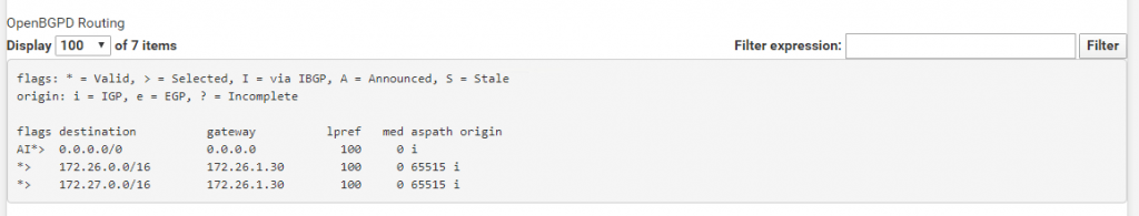
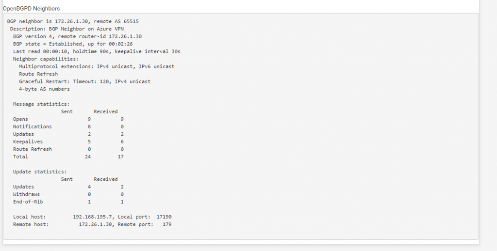
Here you can see that the connection over the BGP protocol was established since 2:26 minutes between pfSense and the Azure BGP peer Neighbor and the AS number 65515.
Under OpenBGPD Routing we will see both address spaces from our Azure VNet wich will be advertised dynamically over the BGP protocol to pfSense.
Further we see the Gateway pfSense will use to route traffic for this VNet. This is the BGP peer IP from Azure.
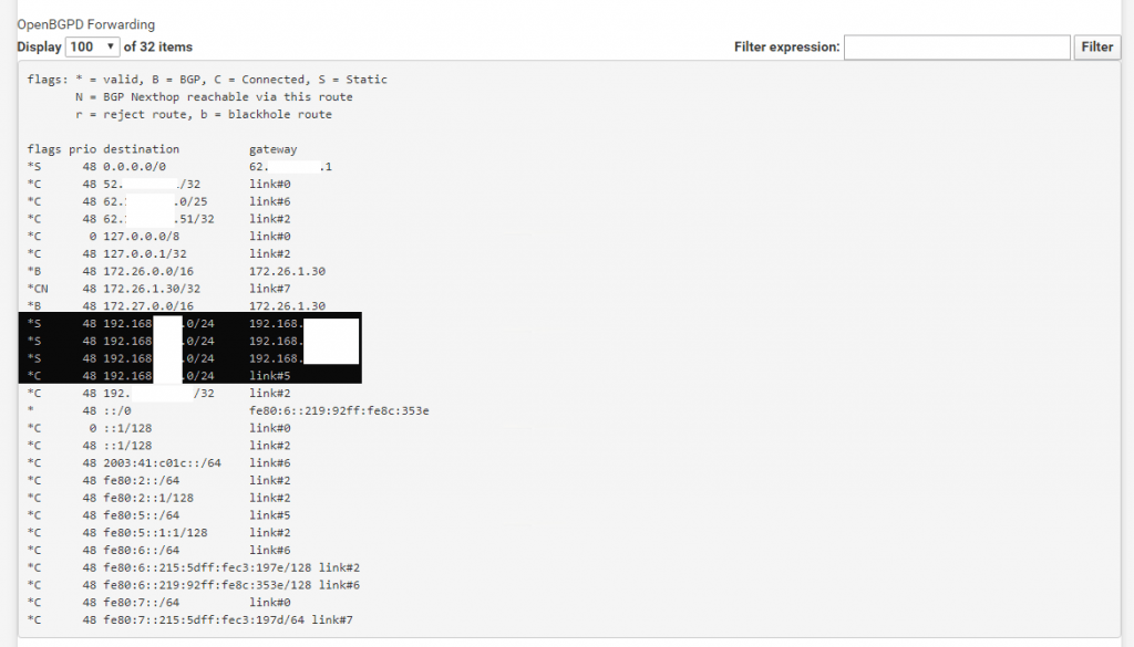
Under OpenBGPD Forwarding we see our internal subnets from the onPremise Network and the corresponding gateway.
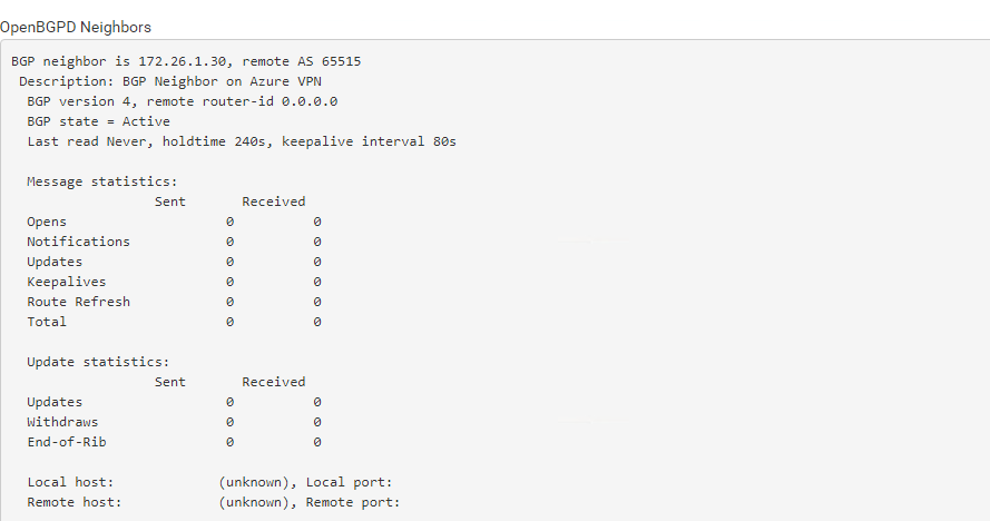
Under OpenBGPD Neighbors we will see the status of both peers.
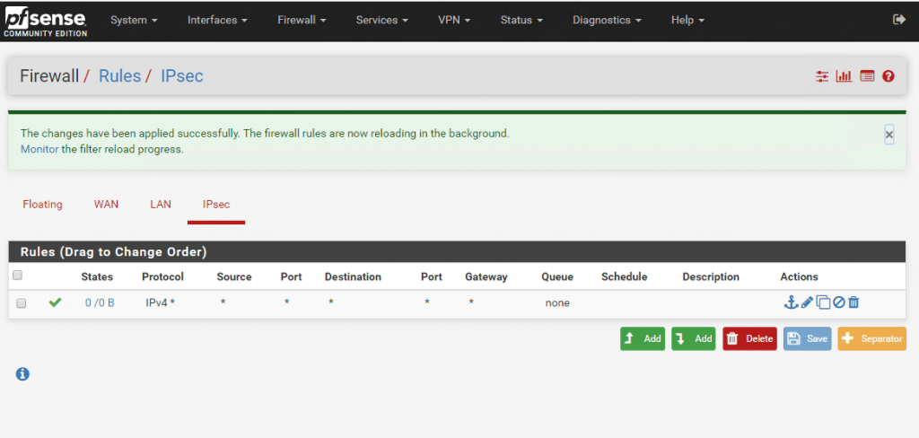
Finally we must allow traffic flow from the Azure VNet to our onPremise network over the IPSec tunnel. The following rule will allow any IPv4 traffic from Azure VNet to the onPremise network. In productive business you should obviously for security reasons only allow required traffic.
Traffic flow from onPremise to Azure you control either from back firewalls in your network or on the LAN Interface at pfSense.
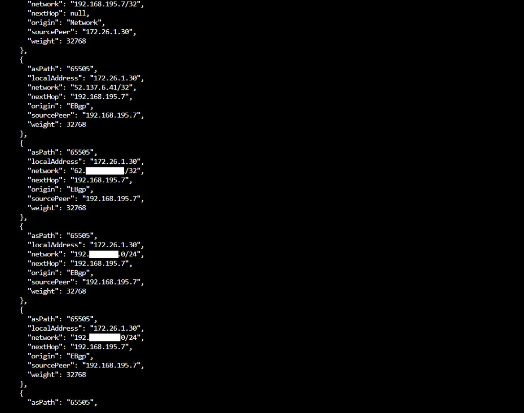
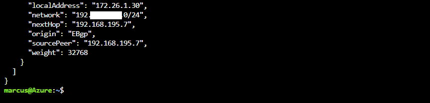
In Azure you can check over the CLI also the advertised routes from pfSense peer to the Azure peer.
$ az network vnet-gateway list-learned-routes -g MyResourceGroup -n MyVnetGateway
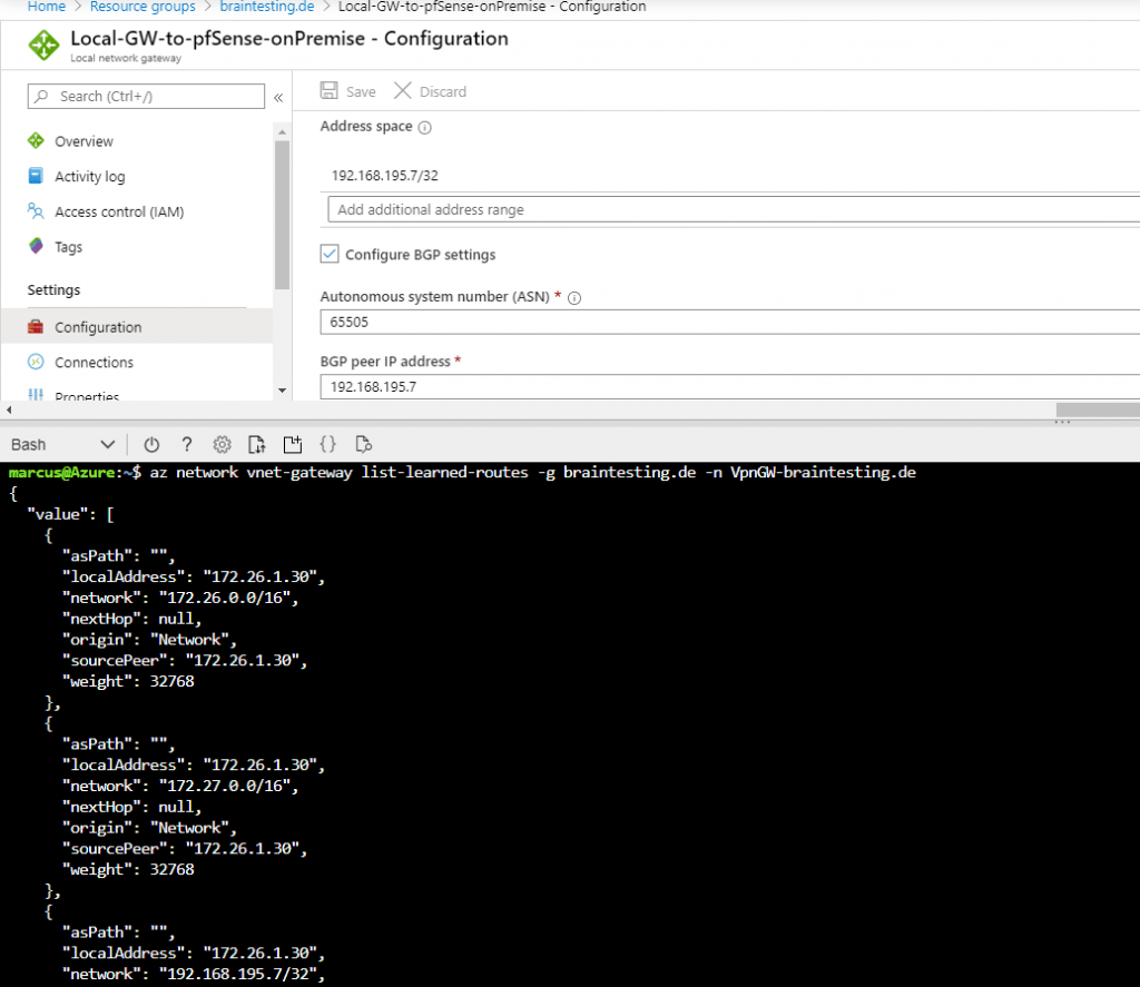
Under https://docs.microsoft.com/en-us/cli/azure/network/vnet-gateway?view=azure-cli-latest you will find an overview of CLI commands for the Virtual Network Gateway.
Troubleshooting
Troubleshooting IPsec VPNs
Due to the finicky nature of IPsec, it isn’t unusual for trouble to arise. Thankfully there are some basic (and some not so basic) troubleshooting steps that can be employed to track down potential problems.
More you will find under https://docs.netgate.com/pfsense/en/latest/troubleshooting/ipsec.html
Duplicate IPsec SA Entries
In certain cases an IPsec tunnel may show what appear to be duplicate IKE (Phase 1) or Child (Phase 2) security association (SA) entries.
After lengthy testing and research, the main way this starts to happen is when both sides negotiate or renegotiate simultaneously. If both peers initiate, reauthenticate, or rekey Phase 1 at the same time, it can result in duplicate IKE SAs. If both peers rekey Phase 2 at the same time, it can result in duplicate child SAs.
Mitigating this problem involves ensuring that the chance of simultaneous negotiation is minimized or eliminated. The easiest way to reach that goal is to set higher Phase 1 and Phase 2 lifetimes on one peer, or at least make sure both sides are not set identically.
Source: https://docs.netgate.com/pfsense/en/latest/troubleshooting/ipsec-duplicate-sa.html
Set up IPSec route based S2S VPN for AWS and Google’s Cloud VPC
If you are also interested about how to set up the same for Amazon’s AWS VPC, you can read my following post.
For Google’s Cloud VPC you can read my following post.