Deploying pfSense in Google Cloud – A Step-by-Step Guide to Your Own Cloud Firewall
Running pfSense in Google Cloud Platform (GCP) is a powerful way to build your own fully controllable network gateway, firewall, or NAT appliance, far beyond what GCP’s managed load balancers or Cloud NAT can offer.
Unlike commercial NGFW appliances such as Fortinet, Check Point, or Palo Alto, which are available in the GCP Marketplace but come with additional licensing costs, pfSense provides a free and open-source alternative that can still deliver advanced firewalling, routing, and VPN capabilities.
From a pure network security and routing perspective, pfSense (and its FreeBSD underpinnings) can absolutely hold its own against most commercial NGFWs.
The difference isn’t in firewall strength, it’s mainly in enterprise polish, automation, and integrated cloud management that vendors charge for.
In this post, we’ll walk through how to deploy pfSense as a virtual machine in GCP, attach it to multiple VPC networks (trusted and untrusted zones), and configure it as a central gateway for routed and NATed traffic.
We will also learn how to handle GCP-specific quirks like MTU adjustments, ILB health checks, and outbound NAT behavior, all the small but essential details that make pfSense work reliably in a cloud environment.
About deploying pfSense in Azure you can read my following post.
- Introduction
- NGFW Appliance Term
- Download pfSense
- Uploading the re-compressed and renamed pfSense tar.gz File to Google Cloud (Bucket)
- Creating the pfSense Image in GCP
- Bootstrapping pfSense: Creating the Temporary Installer Instance (by using our previously created pfSense Image disk)
- Install pfSense
- Create a Snapshot of the Disk we installed pfSense
- Spin up the Production pfSense VM instance (by using the Snapshot)
- Spin up the Production pfSense VM instance (by using a Custom Image)
- Adjusting the MTU in pfSense to Match Google Cloud’s Network Fabric
- pfSense Configuration (Web UI)
- Configure pfSense to reply to ILB Health Checks
- Configuring Outbound NAT for VPC Workloads
- Allow Web UI Access from the Internet
- Troubleshooting
- Links
Introduction
Unlike in Azure or AWS, the GCP Marketplace doesn’t include pfSense, so you can’t spin it up with a single click.
Instead, you’ll need to prepare a custom boot disk, install pfSense manually, snapshot it, and create a reusable image for future deployments, a clean, repeatable path to your own managed firewall instance.
Below we will deploy pfSense as a central firewall appliance within a Google Cloud hub-and-spoke architecture. The pfSense instance will feature two network interfaces, one connected to an untrusted VPC handling internet-facing connectivity, and another attached to a trusted VPC used for internal communication.
Both VPCs together form the hub, acting as a transit layer for traffic between the internet and connected spoke networks.
This setup allows us to secure and inspect both north-south traffic (from the internet to GCP) and east-west traffic (between spoke VPCs and shared services in the hub) through a single pfSense gateway.
In on-prem and cloud networking, traffic is typically categorized as north-south or east-west, depending on its direction and purpose.
North-south traffic refers to data moving into or out of the cloud environment or on-prem, for example, between virtual machines and the internet, or between users and public-facing applications. It represents the traditional perimeter flow where security controls such as firewalls, NAT gateways, or load balancers inspect and manage ingress and egress traffic.
In contrast, east-west traffic describes internal communication that happens within the cloud or on-prem, such as between virtual machines, VPCs/on-prem networks, or application tiers. This lateral movement is often more frequent and can carry sensitive data, which makes it equally important to secure through segmentation, internal firewalls, or micro-segmentation policies.
In short, north-south is about controlling what enters and leaves your environment, while east-west focuses on what moves inside it.
NGFW Appliance Term
A Next-Generation Firewall (NGFW) is a modern security appliance that goes beyond traditional port- and protocol-based filtering by providing deep packet inspection, application awareness, and user-level control.
Unlike classic firewalls that only decide based on source, destination, and port, an NGFW can identify and enforce policies on specific applications, users, and content, even when traffic uses common ports or encrypted protocols.
Most NGFWs integrate capabilities such as intrusion prevention (IPS), malware and threat detection, URL or DNS filtering, and advanced logging and analytics.
This makes them suitable not just for perimeter defense but also for segmentation, compliance, and secure hybrid-cloud connectivity in modern network environments.
pfSense and NGFW Capabilities
pfSense can effectively function as a Next-Generation Firewall, especially when extended with its rich ecosystem of security packages.
Out of the box, pfSense provides stateful packet inspection, VPN, routing, and user authentication, and when combined with add-ons such as Snort or Suricata for intrusion prevention and pfBlockerNG for threat intelligence and DNS filtering, it reaches full NGFW capability.
While commercial solutions like Palo Alto or Fortinet integrate these features more tightly, pfSense offers a flexible, modular, and cost-effective alternative for both enterprise labs and production environments.
Download pfSense
We first need to download pfSense from one of the following links.
https://www.pfsense.org/download
https://atxfiles.netgate.com/mirror/downloads
We then first need to extract the downloaded *.iso.gz file to get the *.img file and then compress back to *.tar.gz. which is supported by Google Cloud to create an image from.
After extracting the file we first need to rename the image file inside.
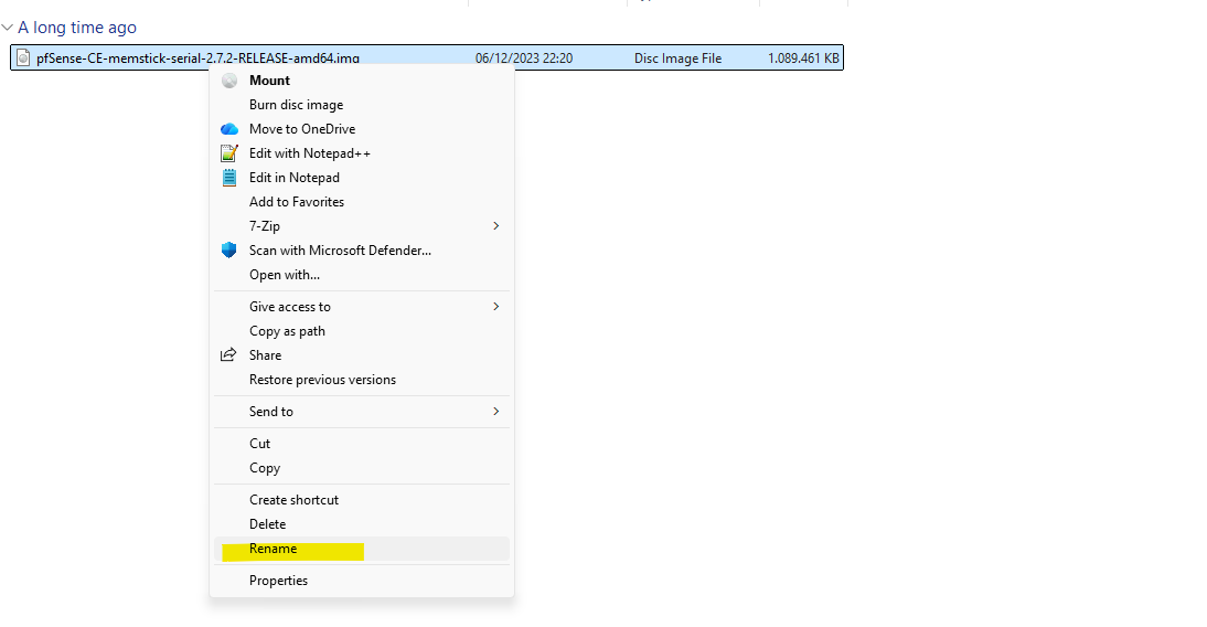
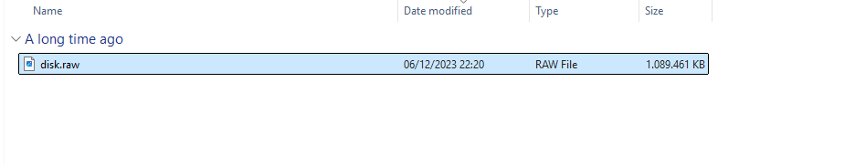
We need to rename the extracted image file into disk.raw (remove also the extension .img) as required to later create a new image in Google Cloud from.
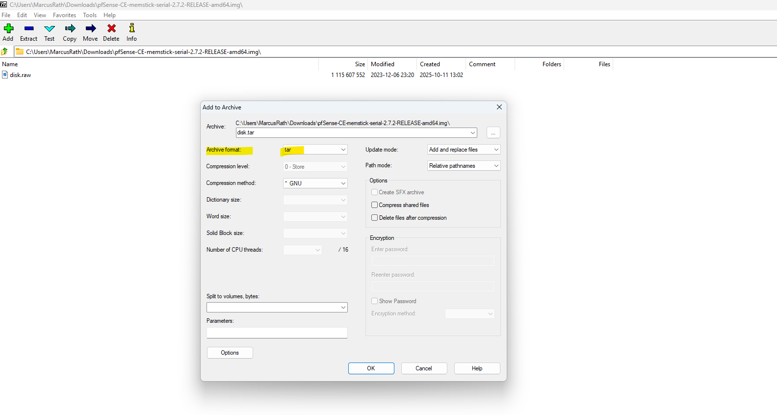
To compress the file again we can use on Windows the 7-Zip tool. Right click on the *.img file and select Add to Archive. For the Archive format select tar.
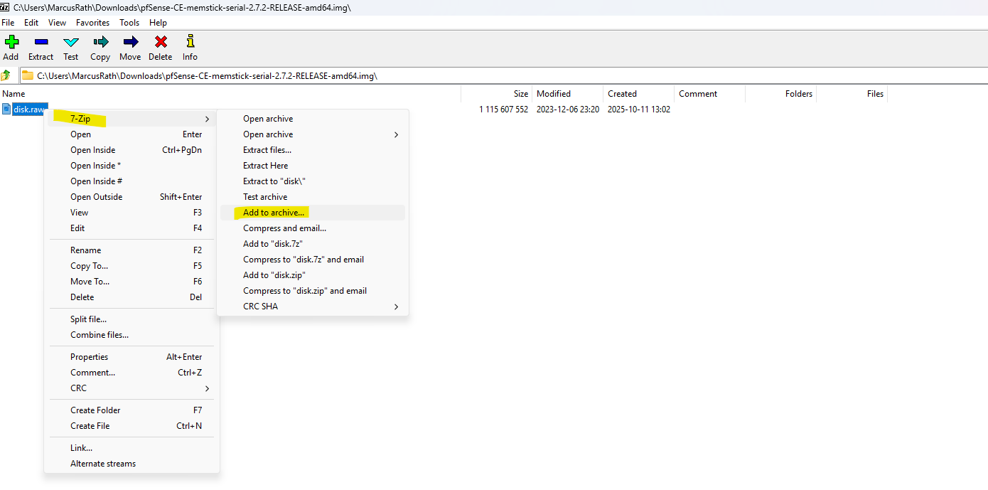
We first compress the installer file to tar, so for the archive format select tar below.
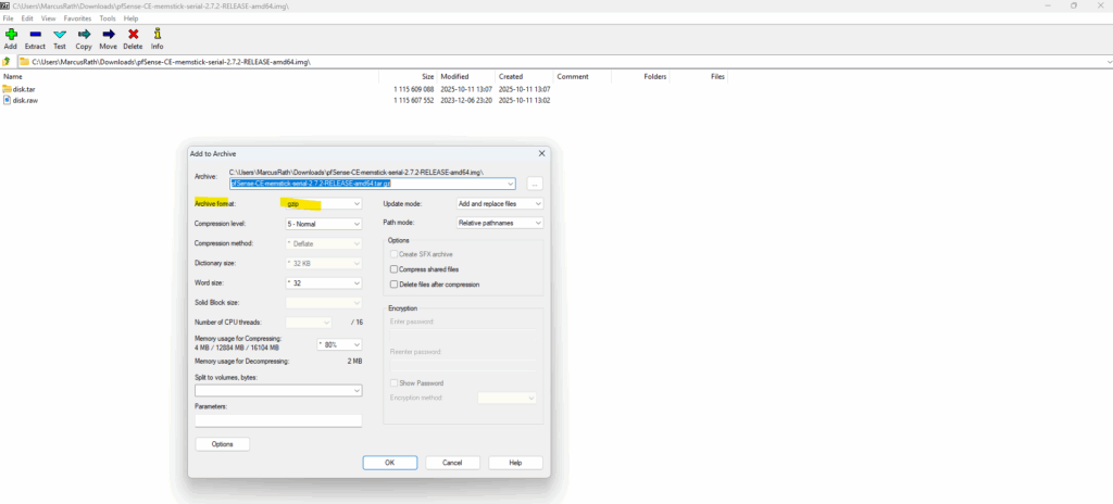
Then add the created *.tar file to archive and select the for the Archive format gzip.
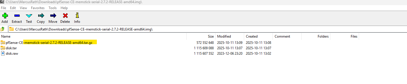
We will now have our required *.tar.gz file and inside the image named disk.raw as required to create a new image in Google Cloud.
Your image source must use the .tar.gz extension and the file inside the archive must be named disk.raw.
Source: https://cloud.google.com/compute/docs/import/import-existing-image#create_image_file
Uploading the re-compressed and renamed pfSense tar.gz File to Google Cloud (Bucket)
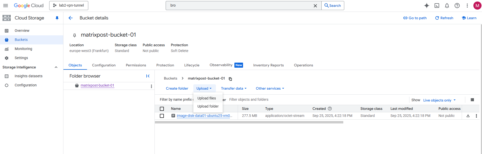
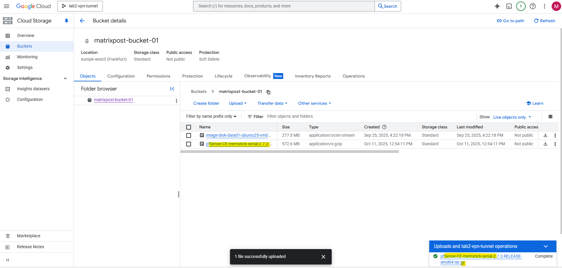
To deploy pfSense in Google Cloud, we first need to upload the installer image (re-compressed and renamed to match GCP’s import format) into a Cloud Storage bucket.
The bucket acts as a staging location from which GCP’s image import service can create a custom bootable disk image.
Once uploaded, the pfSense image can be imported into Compute Engine → Custom Images and used to launch new firewall instances.
Upload the file to Google Cloud -> Cloud Storage -> Bucket.
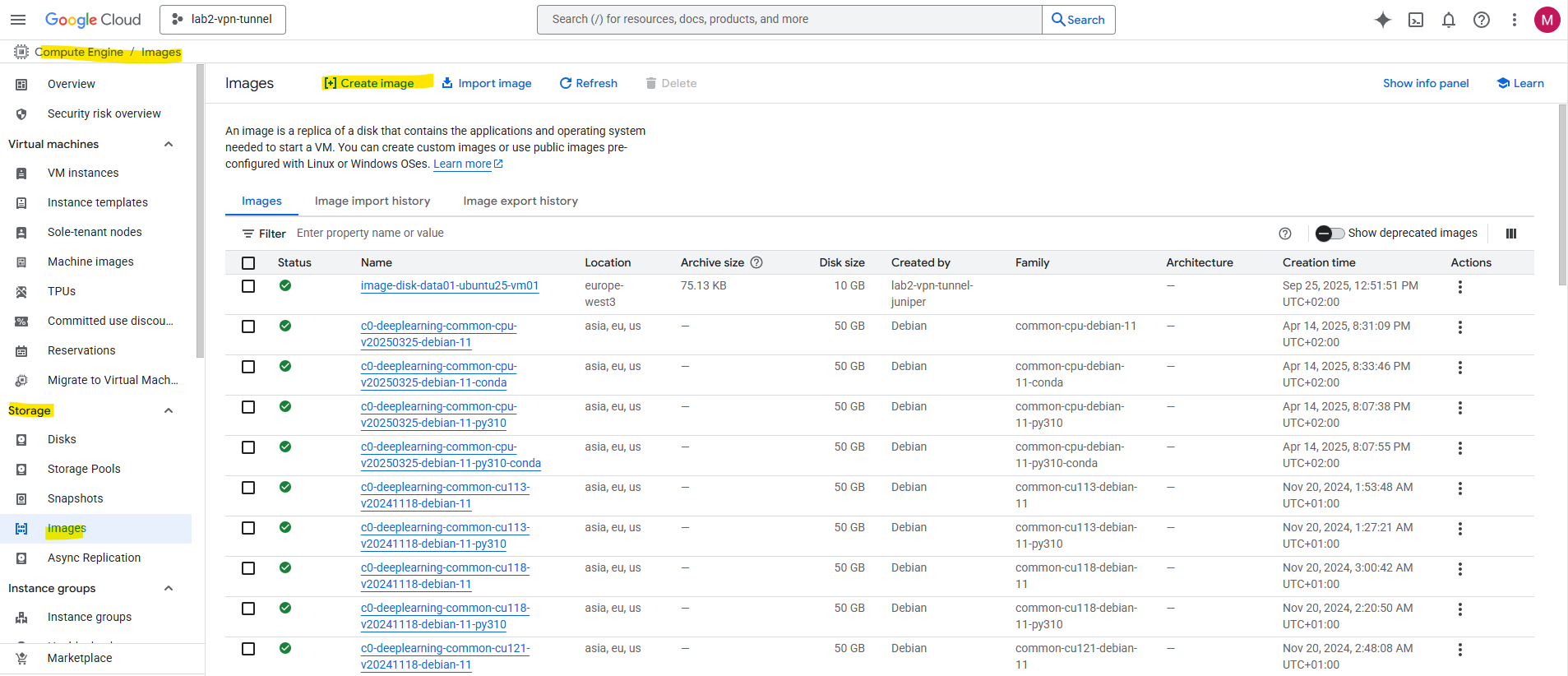
Creating the pfSense Image in GCP
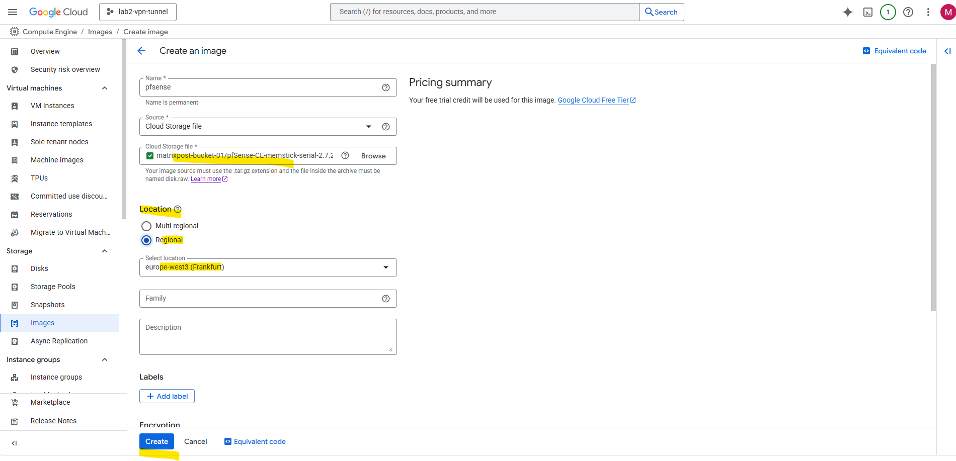
After uploading the pfSense installer image to our Cloud Storage bucket, we can create a new custom image in Compute Engine → Images by selecting “Create Image” and choosing Cloud Storage file as the source.
GCP will automatically import and convert the uploaded pfSense installer into a bootable disk image.
This image doesn’t contain a ready-to-run pfSense system, it simply acts as a bootable installer disk, much like mounting an ISO in a hypervisor.
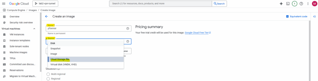
Enter a name for the new image and select for the source here Cloud Storage file.
Better use a unique name here like pfsense-bootable-installer-disk to avoid later mixing up the image with the “real image” we can use to create a new VM instance.
We will later also create a real custom image we can use to directly spin up production pfSense VM instances.
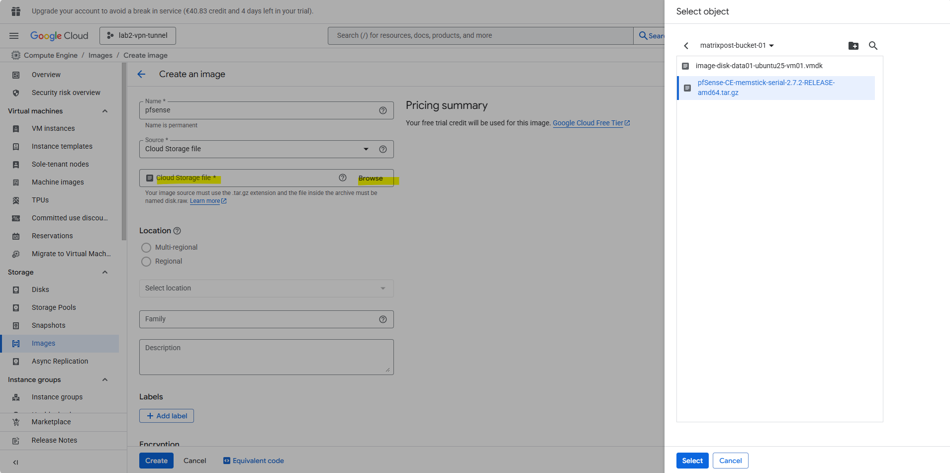
Select the bucket we have uploaded pfSense and select our uploaded *tar.gz file.
Your image source must use the .tar.gz extension and the file inside the archive must be named disk.raw.
Source: https://cloud.google.com/compute/docs/import/import-existing-image#create_image_file
We need to select our correct region to later be able to use this image. Finally click on Create.
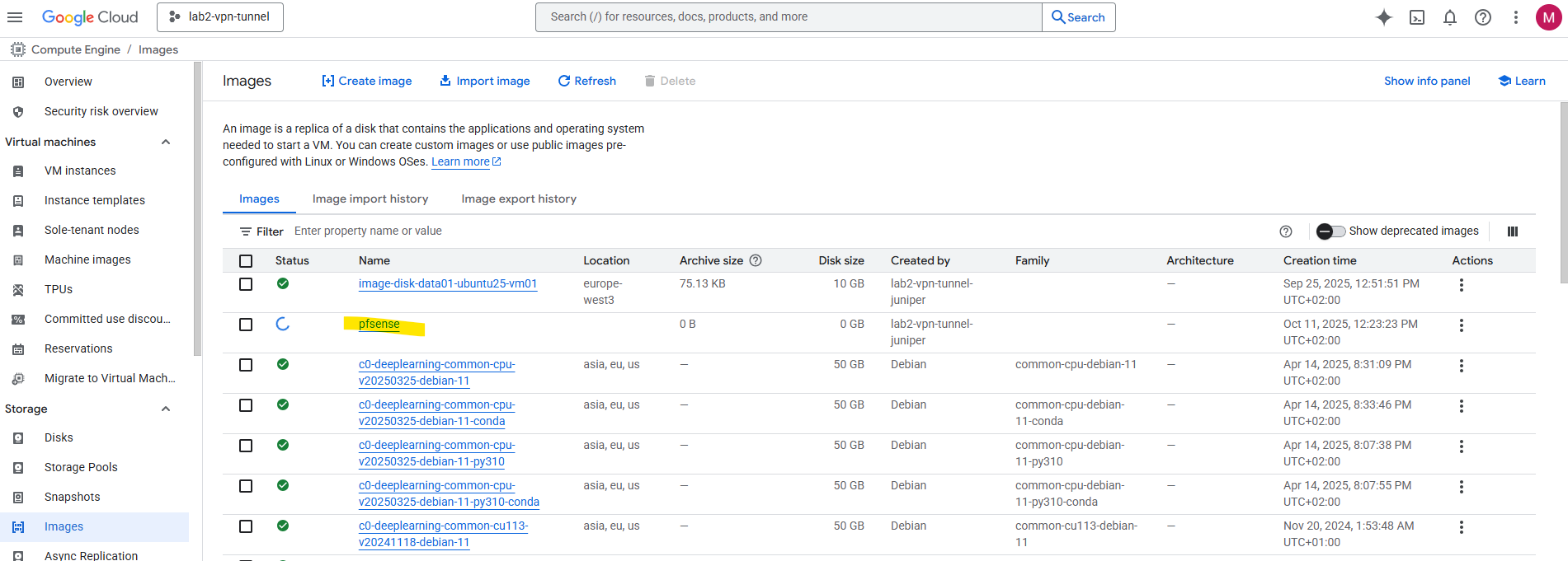
The new image will be created.
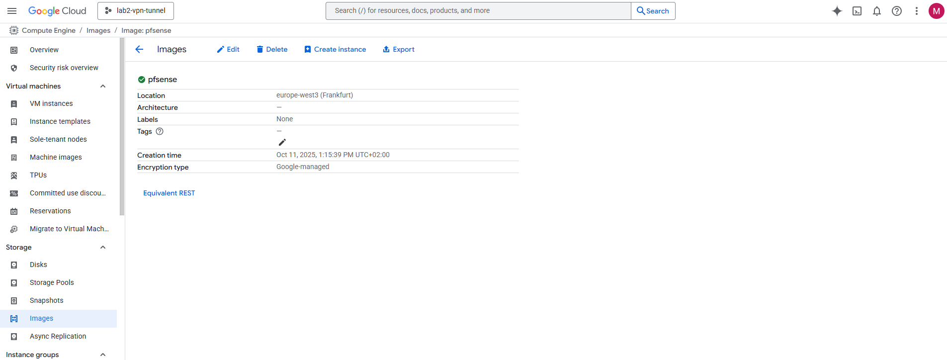
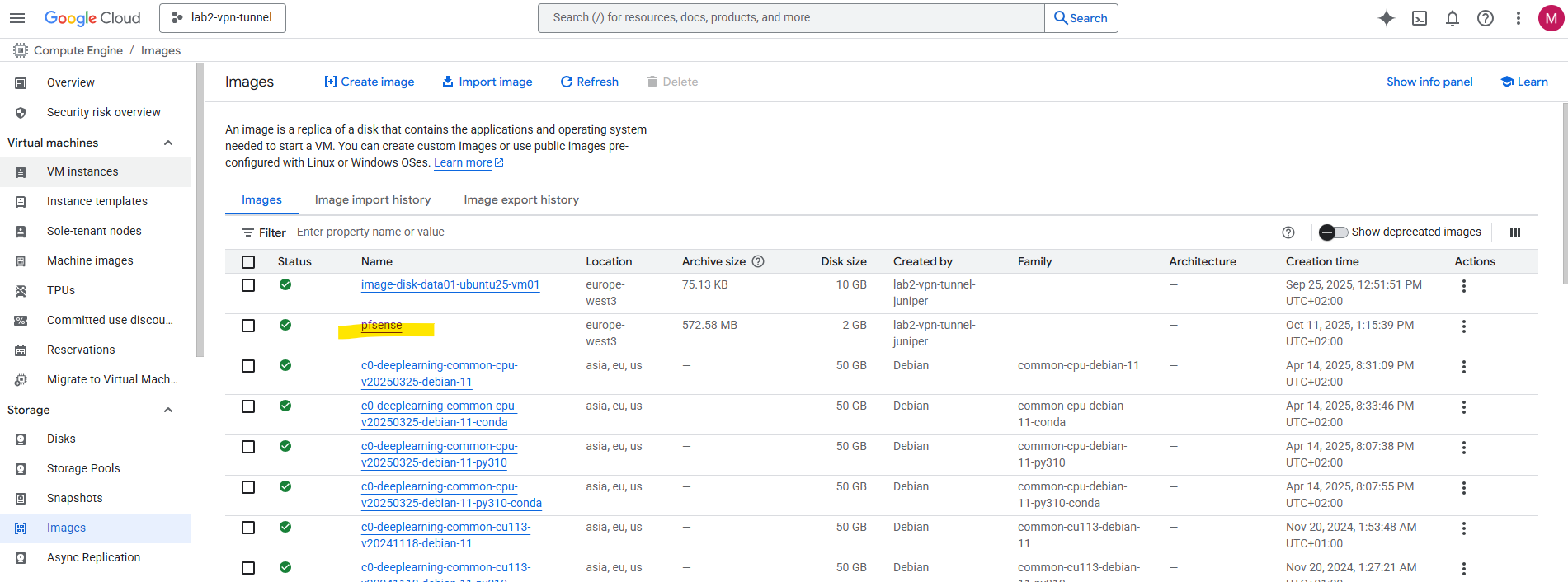
It was finally created successfully.
!! Note !!
In case we didn’t have previously first renamed the downloaded and extracted image file into disk.raw (remove also the extension .img) before re-compressing to *.tar.gz, we are not able to successfully create the new image below.
Bootstrapping pfSense: Creating the Temporary Installer Instance (by using our previously created pfSense Image disk)
Next, launch a temporary VM using this image as the boot disk and attach a second empty disk where pfSense will actually be installed.
Once the installation is complete, we will shut down the VM and take a snapshot of the second disk.
That snapshot is finally our real, deployable pfSense image, the one we will use to spin up production firewall instances in GCP, not the “installer-only” one that just boots into setup.
On the OS and storage tab click on Change.
Switch to the Custom images tab and search for our previously created pfSense image. Select the pfSense image. The rest leave on its default settings and click Select.
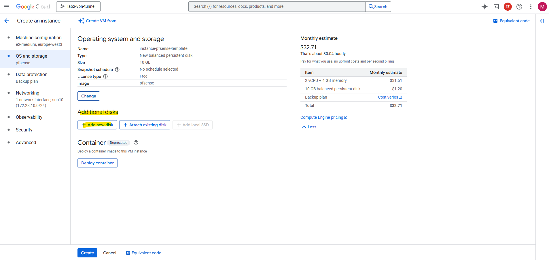
This disk will be just our bootable installer disk as mentioned, much like mounting an ISO in a hypervisor. Next we add a second empty disk where pfSense will finally be installed on.
Click on Add new disk. This will be our disk we will install pfSense on as mentioned.
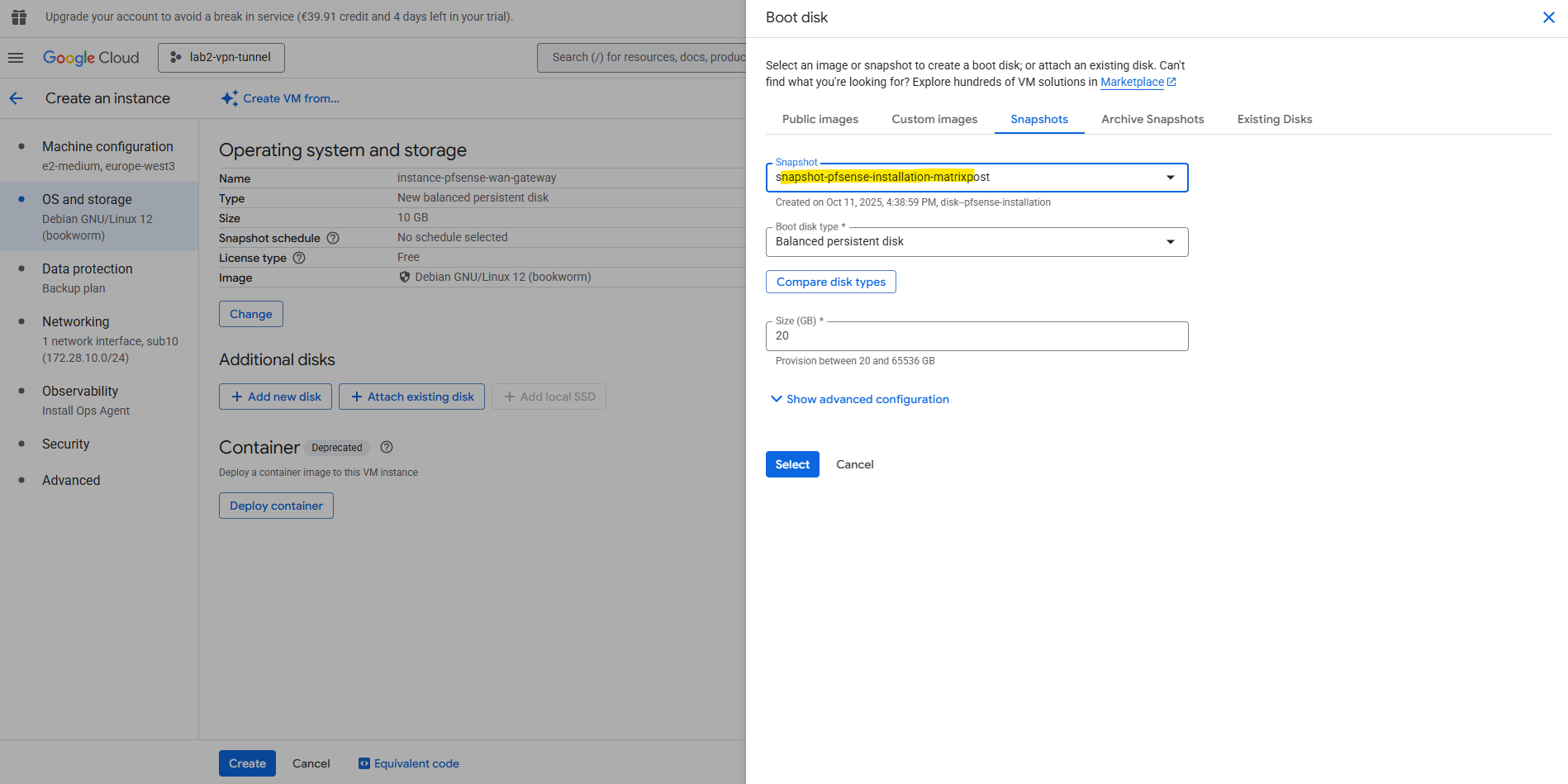
Enter a name for the disk. The recommended disk size for pfSense is 16 GB, I will finally choose 20 GB. The rest we can leave on the default settings. Click on Save.
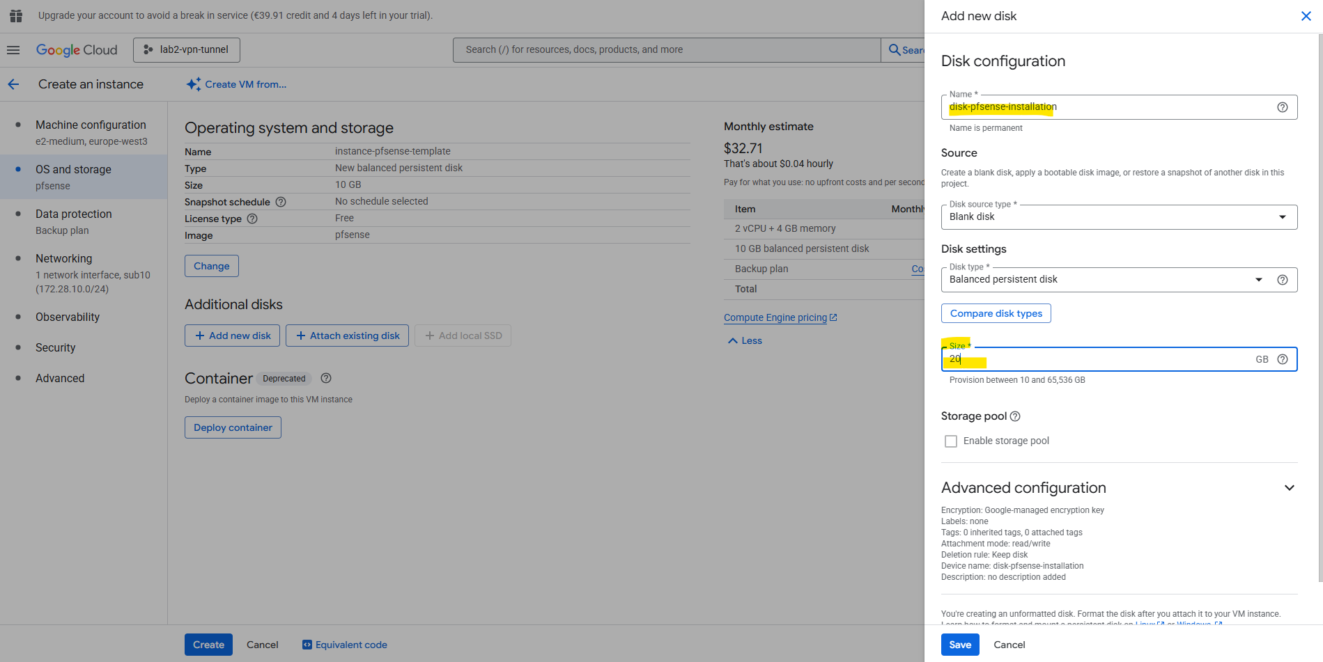
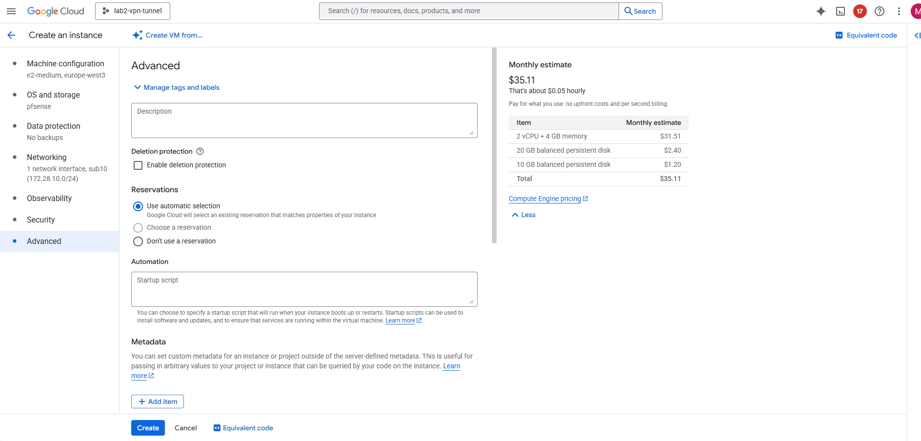
Because this VM instance will just be used to create the disk with the pfSense installation (our final custom pfSense image), the rest of the settings we can also leave on its default settings and doesn’t really matter, including just one network interface.
Later when creating our final pfSense VM instances we will assign at least two network interfaces (trusted Hub VPC and untrusted HUB VPC).
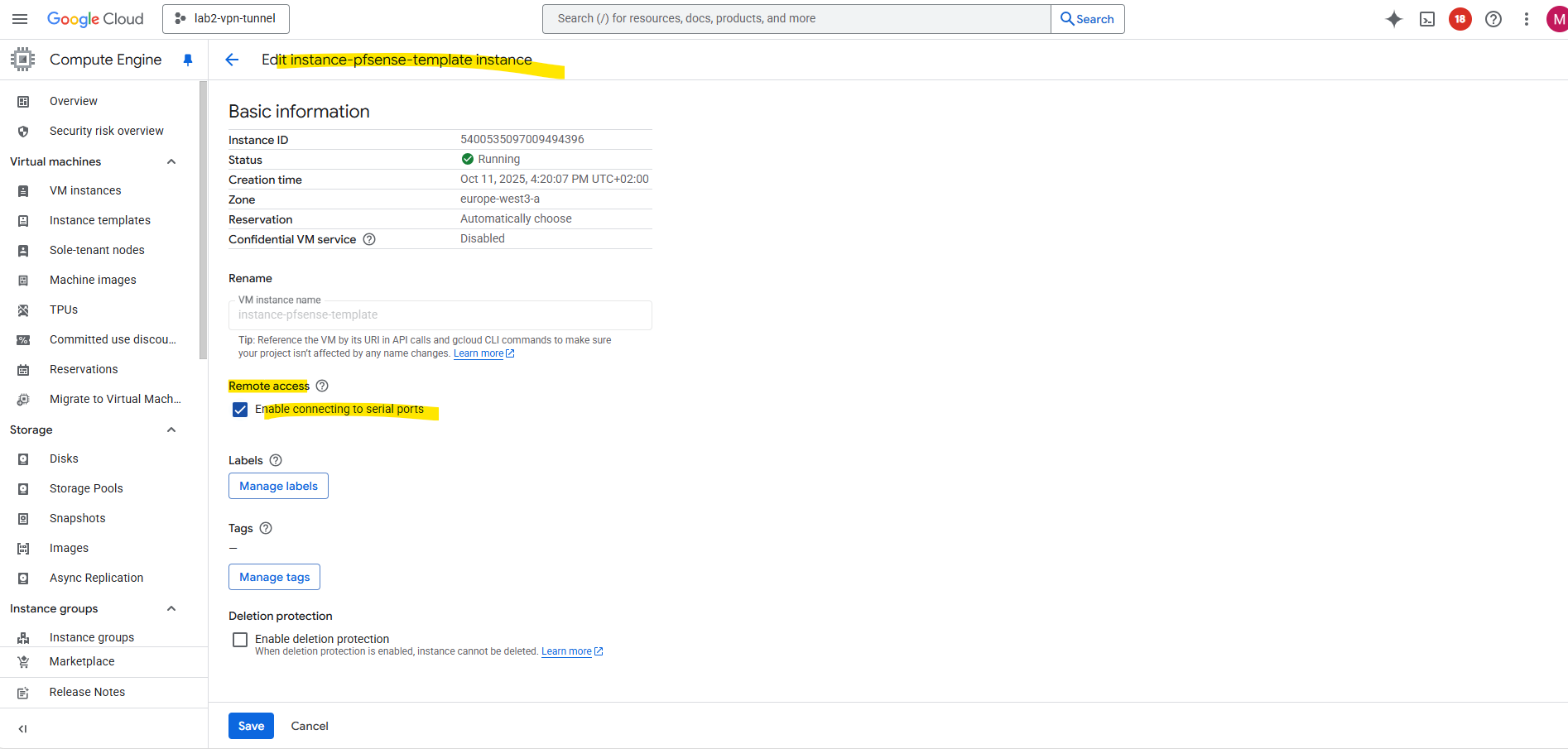
To perform the installation we need to access the serial console of the VM instance. So also enable the serial console on this temporary VM instance.
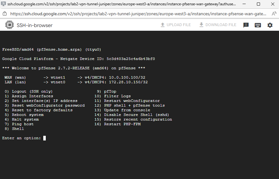
Install pfSense
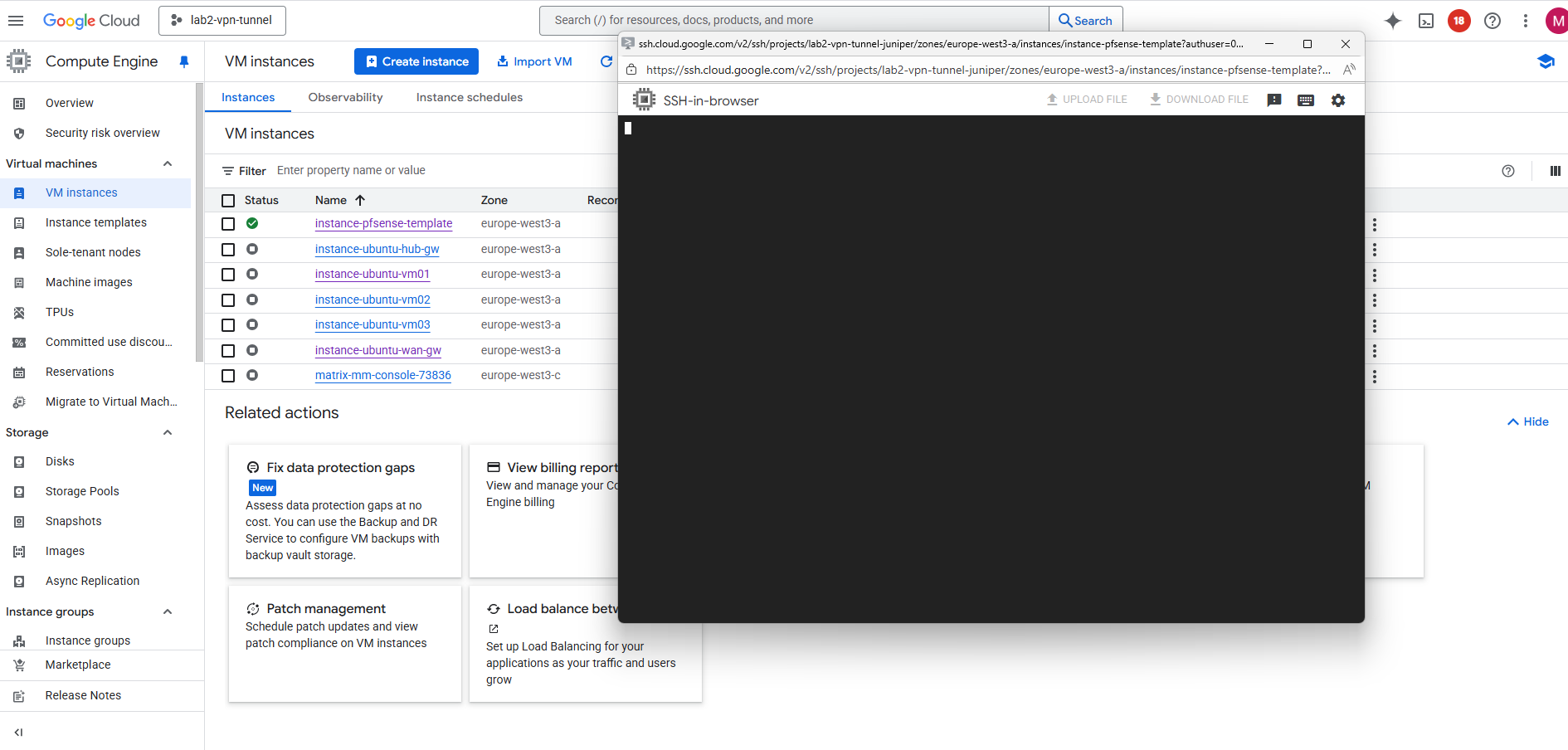
Once the temporary VM is running, the pfSense installer will automatically boot from the custom image disk as the primary boot disk.
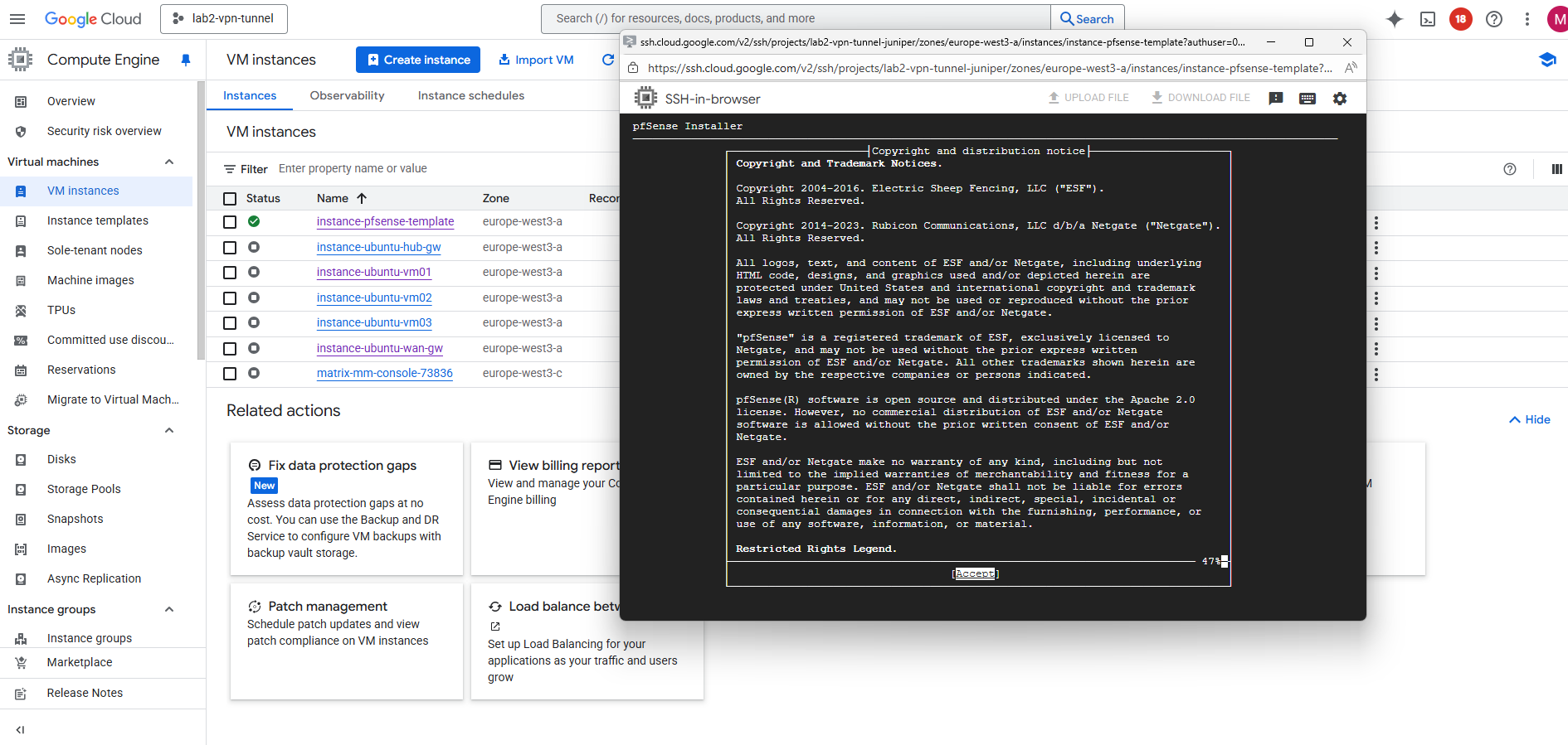
Connect to the serial console and click on enter.
Accept the copyright and distribution notice.
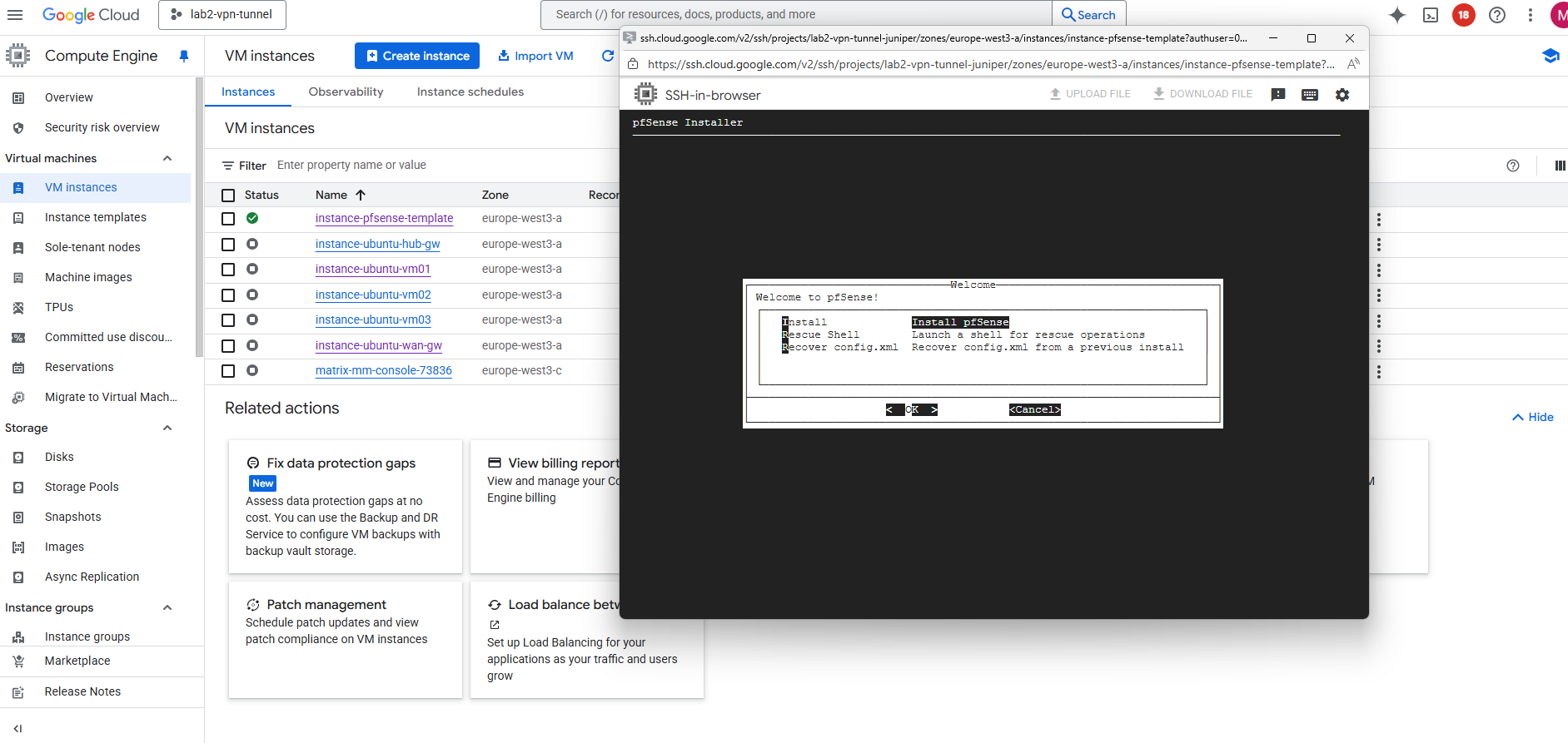
Select Install pfSense.
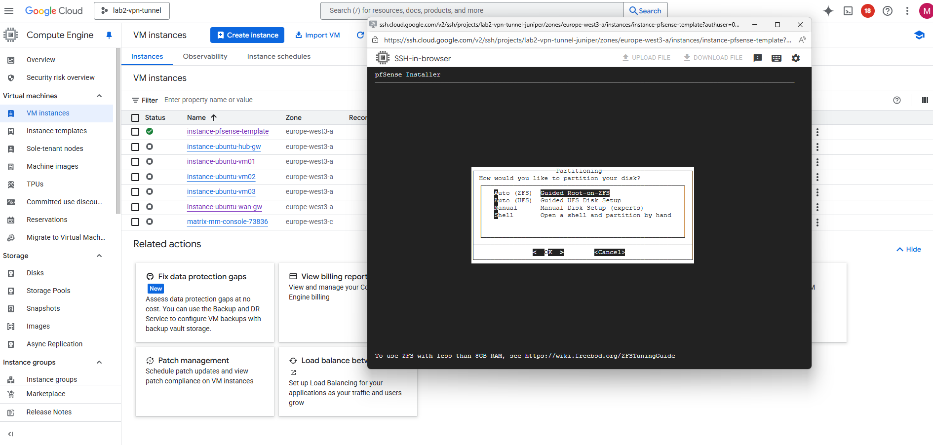
For the partitioning choose between the ZFS and UFS filesystem.
UFS is the traditional, lightweight option that’s simple and fast — ideal for most cloud or virtualized deployments.
ZFS, while more feature-rich with advanced integrity checks and snapshots, adds overhead and is generally only recommended if you need its specific features or plan to run pfSense on larger, persistent storage.
More about both when using pfSense you will also find in my following post https://blog.matrixpost.net/pfsense-boot-loop-after-power-outage/.
Click on Install.
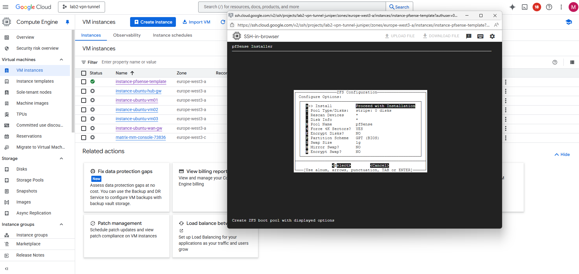
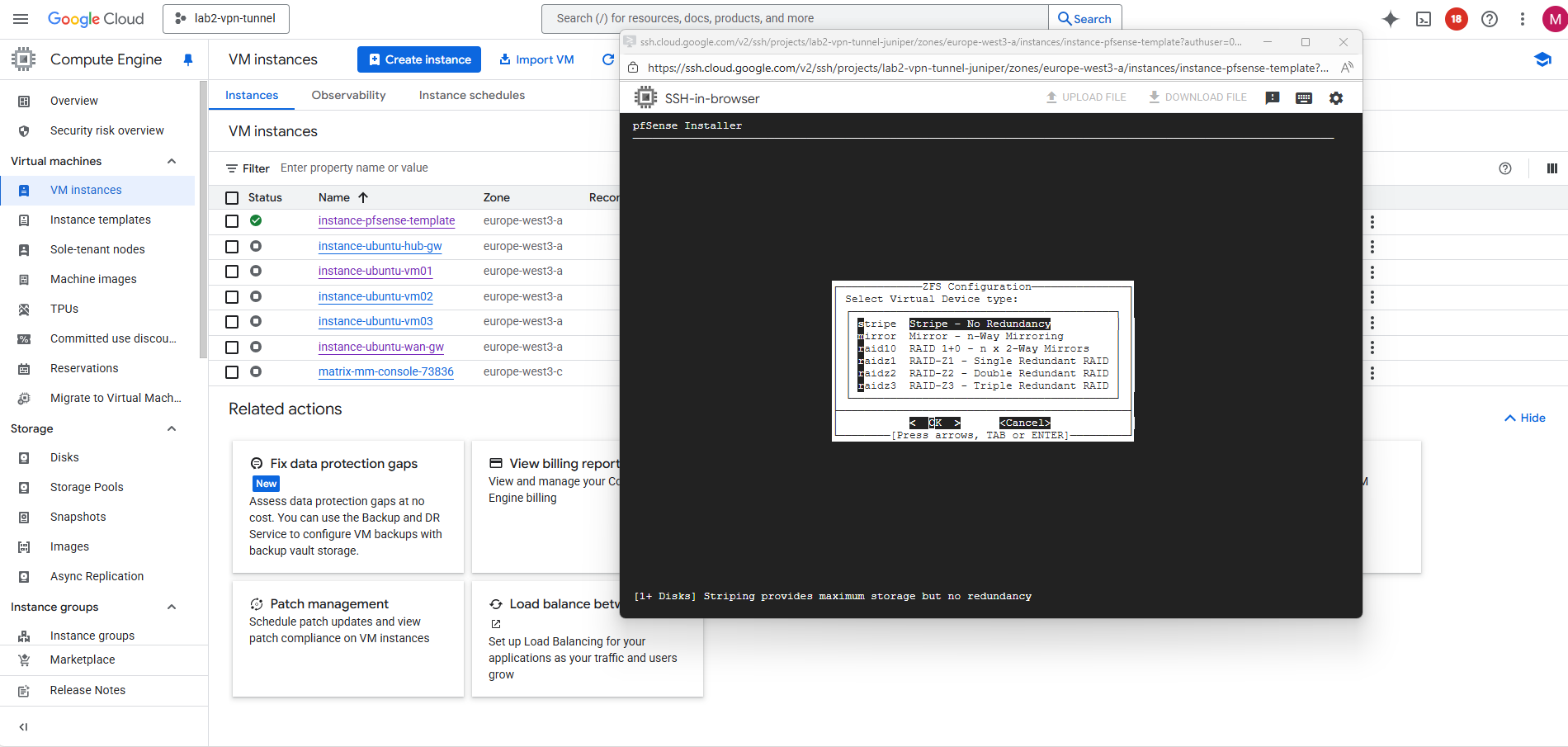
For the virtual device (disk) I will use stripe.
In our GCP setup, using RAID or mirrored ZFS pools inside pfSense makes no real sense and would just add unnecessary overhead.
GCP Persistent Disks (standard or SSD) are already replicated at the storage layer, Google automatically maintains redundancy and durability behind the scenes.
Creating a RAID or mirrored ZFS setup inside the VM would only add CPU and I/O overhead without improving reliability or performance.
Therefore, a simple ZFS stripe (single-disk vdev) or UFS on a single disk is fully sufficient for pfSense in GCP.
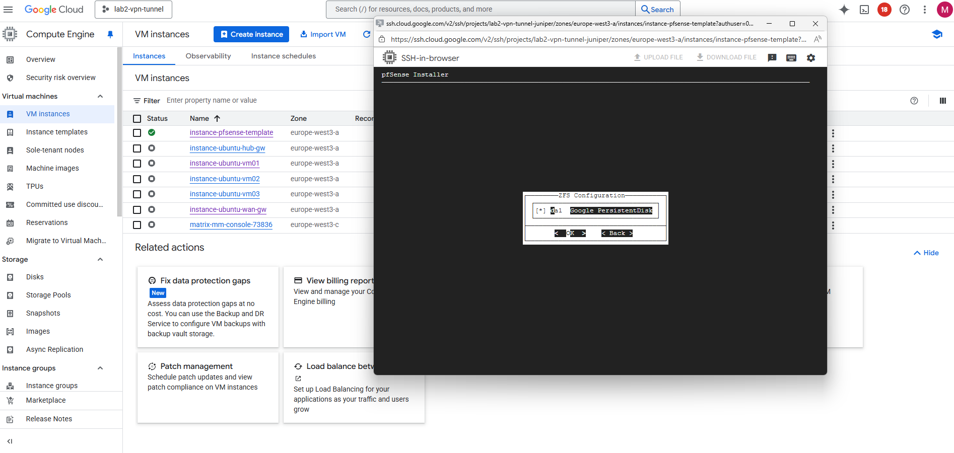
Select the second attached disk as the installation target, this is where pfSense will actually be installed.
Press the space key to select our newly attached disk where we want to install pfSense on.
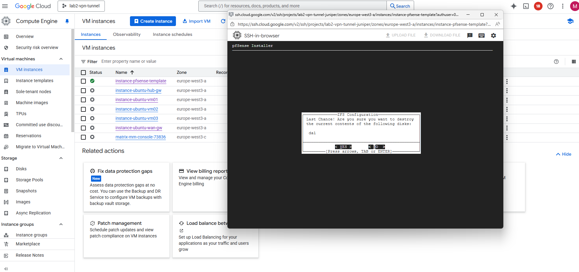
Confirm by pressing yes.
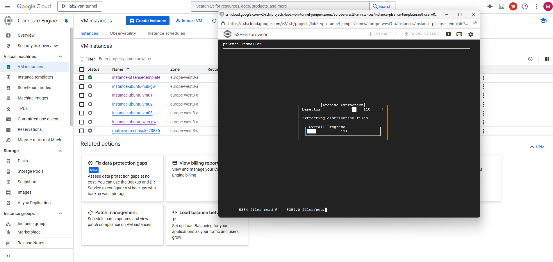
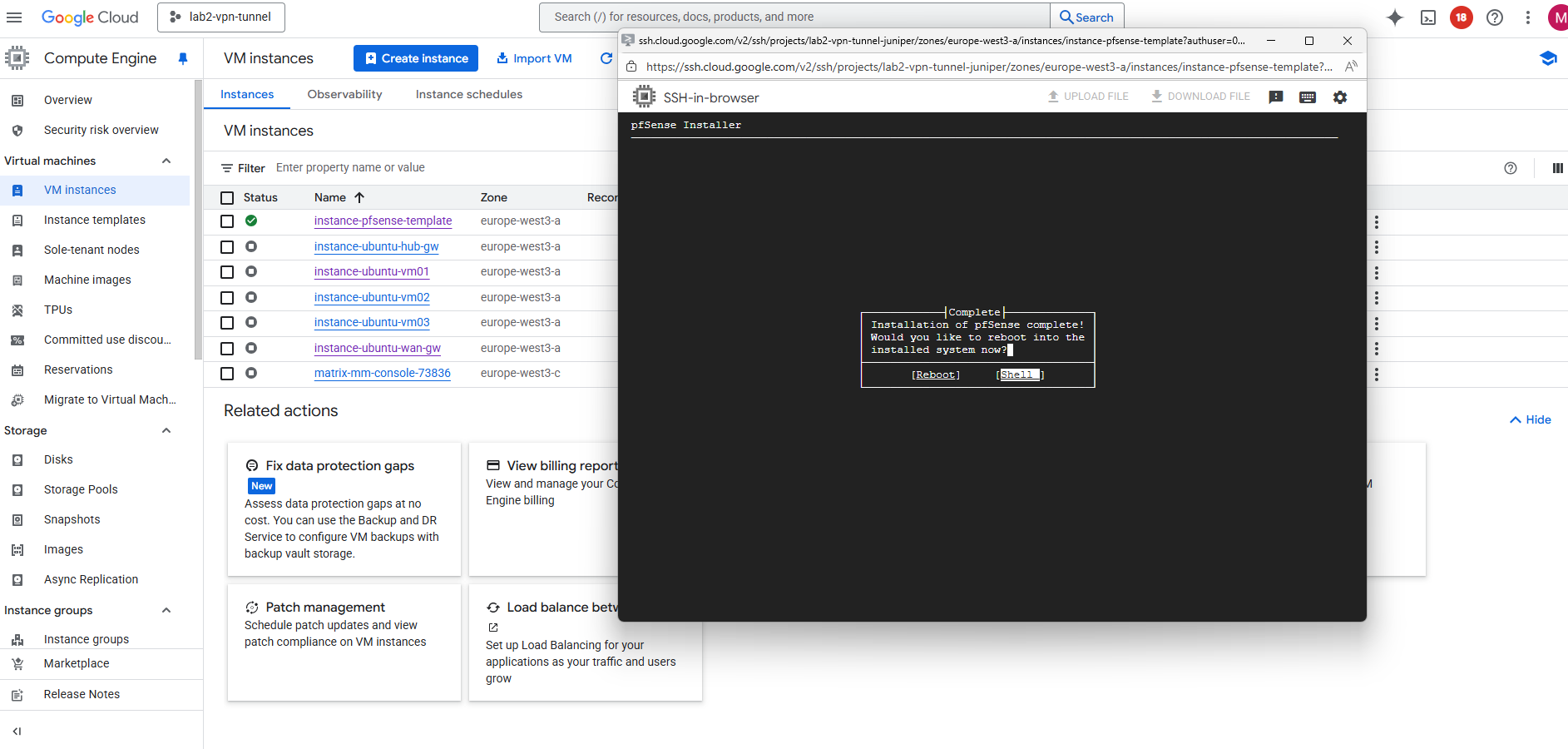
The installation starts.
After the installation completes and pfSense has written its system files to the second disk, shut down the VM to prepare that disk for snapshotting and image creation.
So select Shell.
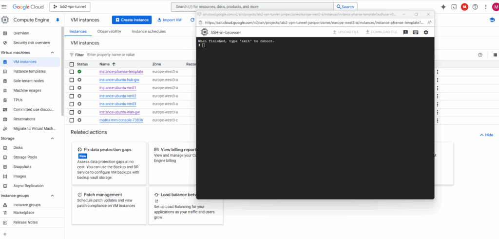
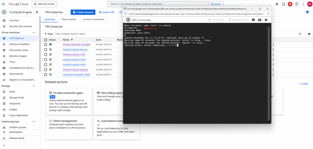
To shutdown pfSense and our VM instance, run:
# poweroff
Create a Snapshot of the Disk we installed pfSense
We will now create a snapshot of the disk on which we installed pfSense previously. By doing this we will have a real, deployable pfSense image we can later use to spin up production pfSense VM instances in GCP.
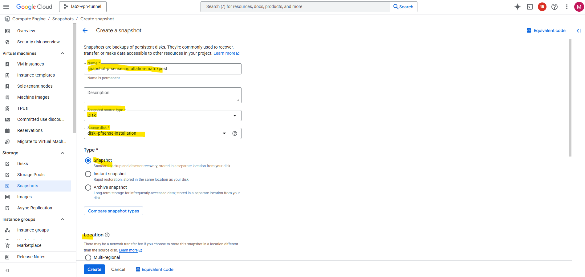
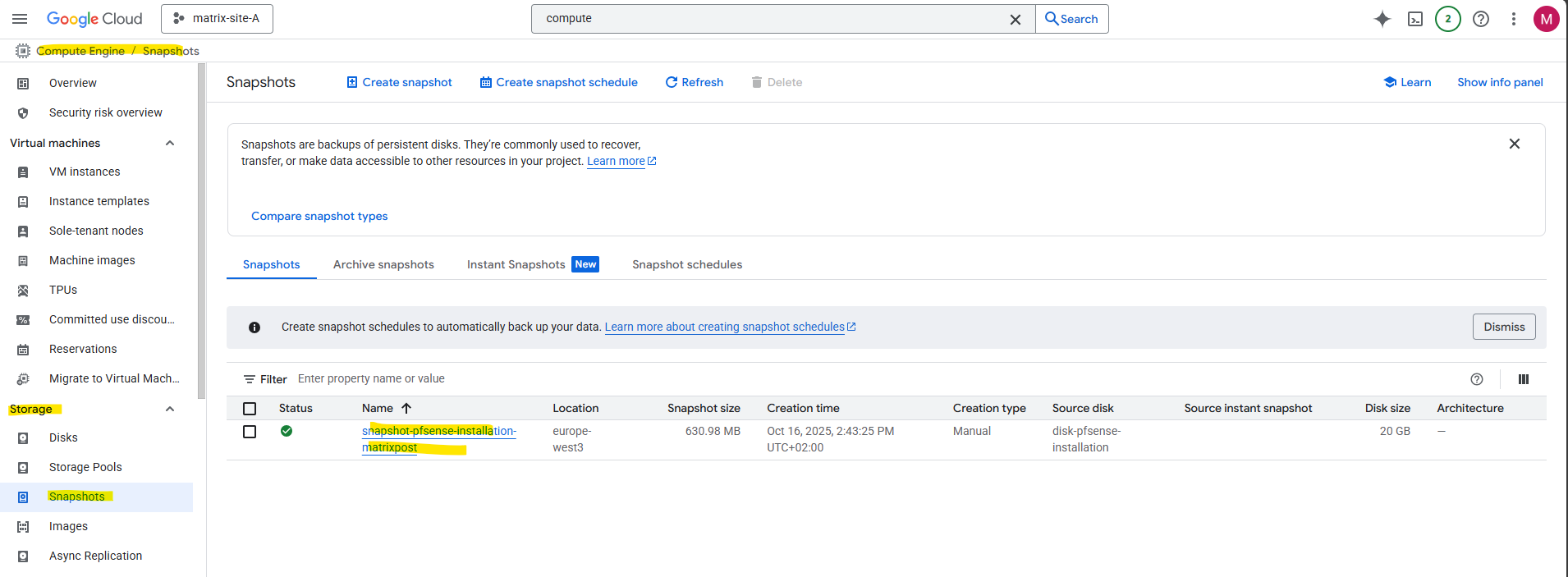
In Compute Engine browse to Storage -> Snapshots and click on + Create snapshot.
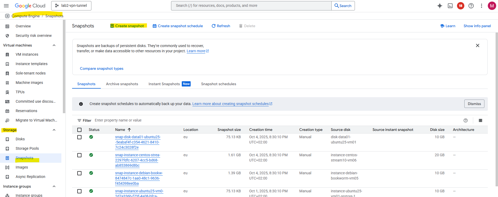
Under source disk select our previously new added disk we installed pfSense on, in my case named disk-pfense-installation, for the type select snapshot and for the location select a region you can access later.
Click on Create.
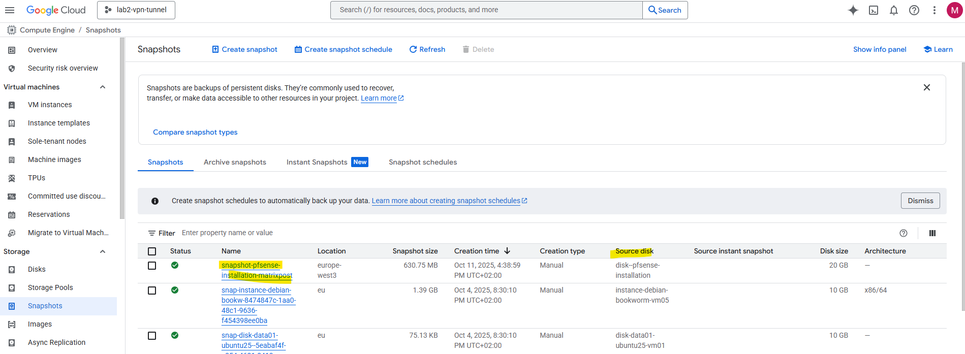
Next we can create our final VM instance with pfSense running on.
Our temporary installer VM instance we can now delete.
Spin up the Production pfSense VM instance (by using the Snapshot)
We can either use our previously created snapshot or a custom image as the boot disk for creating a new VM instance in GCP, they behave differently behind the scenes.
Even we can finally use both the snapshot disk or the custom image as a boot disk to create a new VM instance in GCP, the resulting VM will behave exactly the same. The main difference lies in how Google Cloud manages the source, snapshots act as backups, while custom images are reusable templates optimized for deployment and sharing.
We will first see how to create a new pfSense VM instance by using our previously created snapshot and in the next section by using a custom image created out of this snapshot.
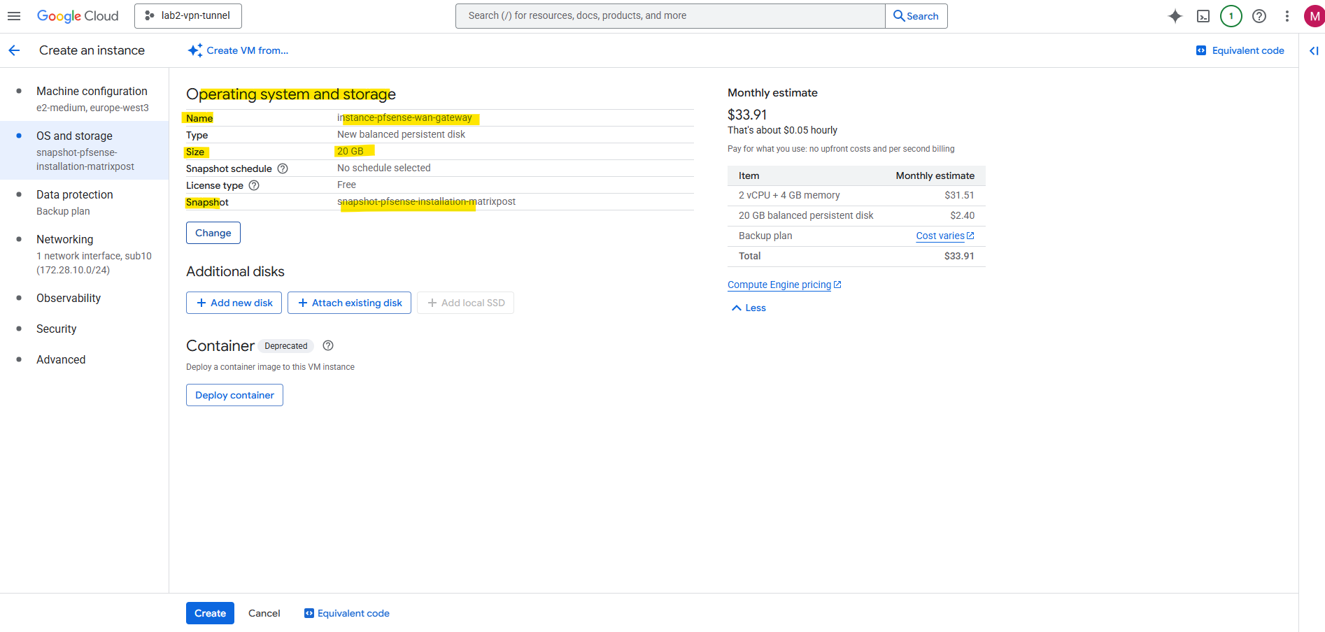
With the final pfSense image (disk snapshot), we can now launch our production pfSense VM instance.
Simply create a new Compute Engine VM and select this custom image as the boot disk, this time it will boot directly into a fully installed pfSense system, not the installer.
From here, we can attach additional NICs for our trusted and untrusted VPCs, enable IP forwarding, and begin configuring pfSense as our central gateway or firewall in GCP.
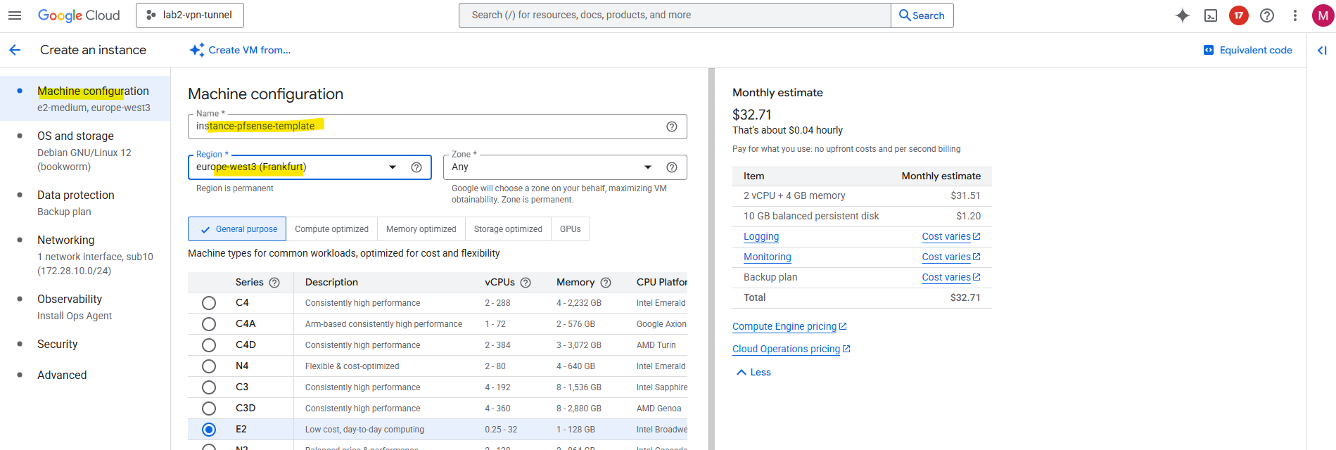
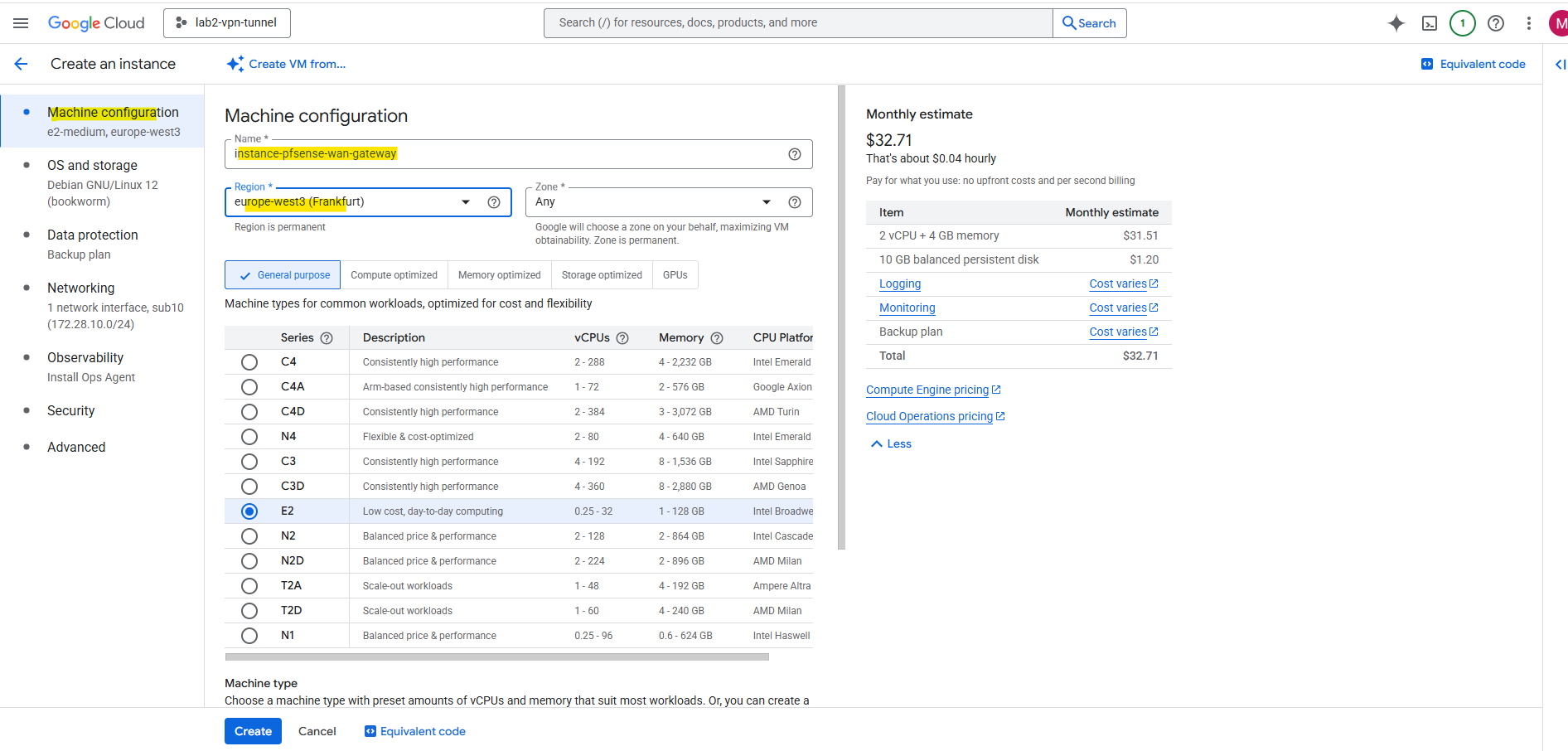
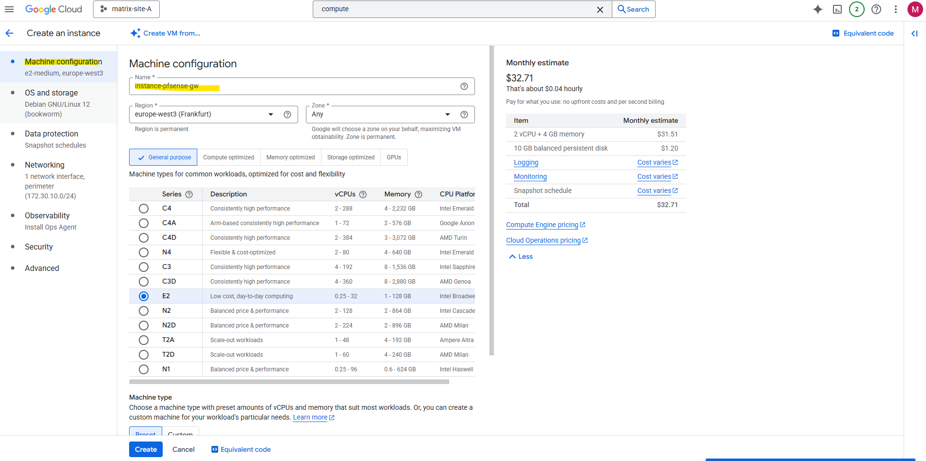
For Machine configuration enter a name and region.
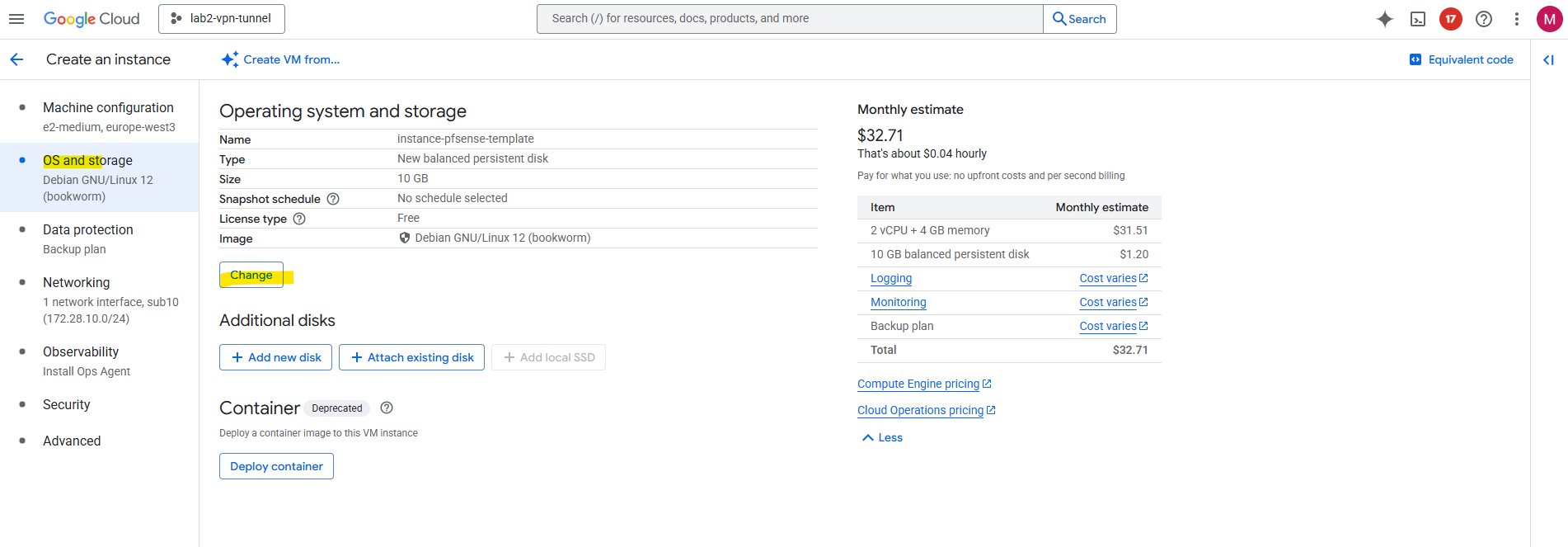
Under OS and storage click on Change.
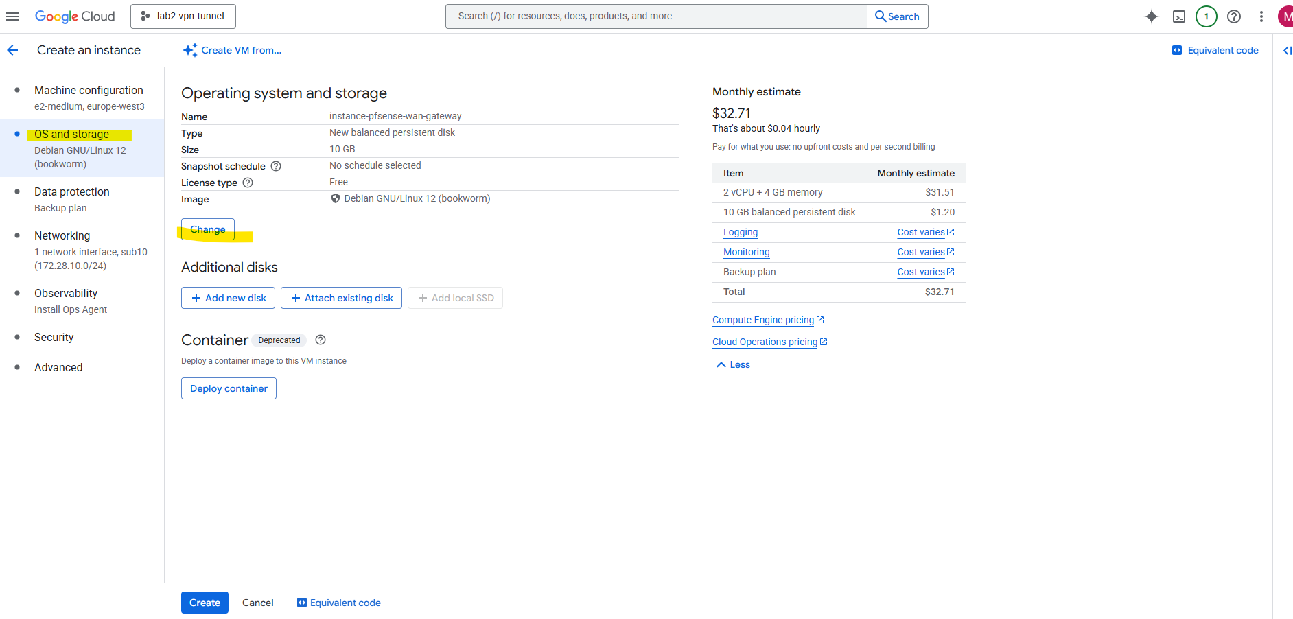
Switch to the Snapshots tab and search for our previously created snapshot (taken of the added new disk we installed pfSense on) and select it.
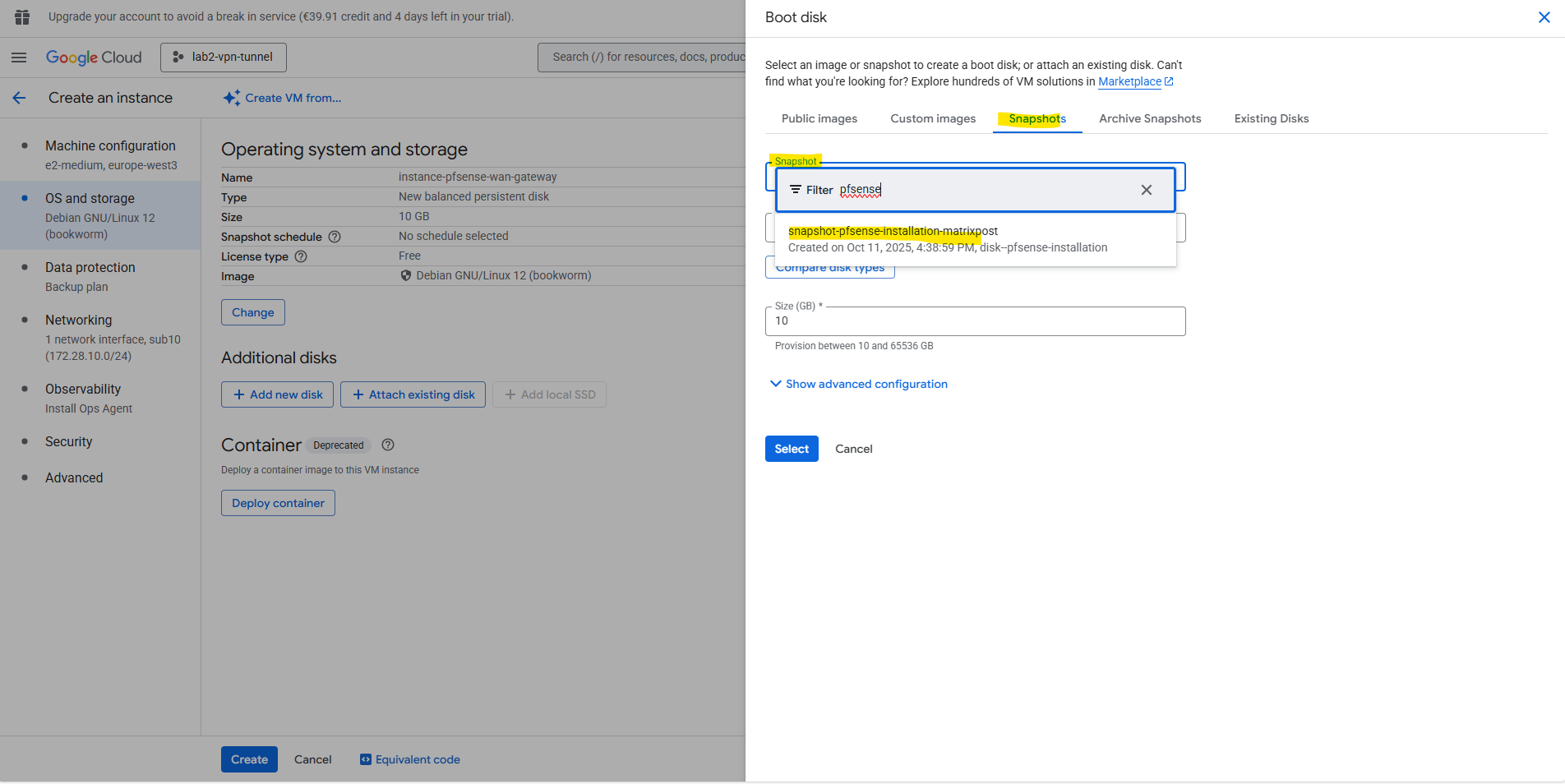
Click on Select.
For the network we will attach two NICs which both are associated with Hub VPCs (trusted and untrusted). Further I will enable IP forwarding (in GCP in general on the VM level).
Enabling IP forwarding applies to all of the NICs on the VM.
Source: https://cloud.google.com/vpc/docs/using-routesIn Azure, we enable IP forwarding directly on the NICs and not at the VM level, as shown in my post here.
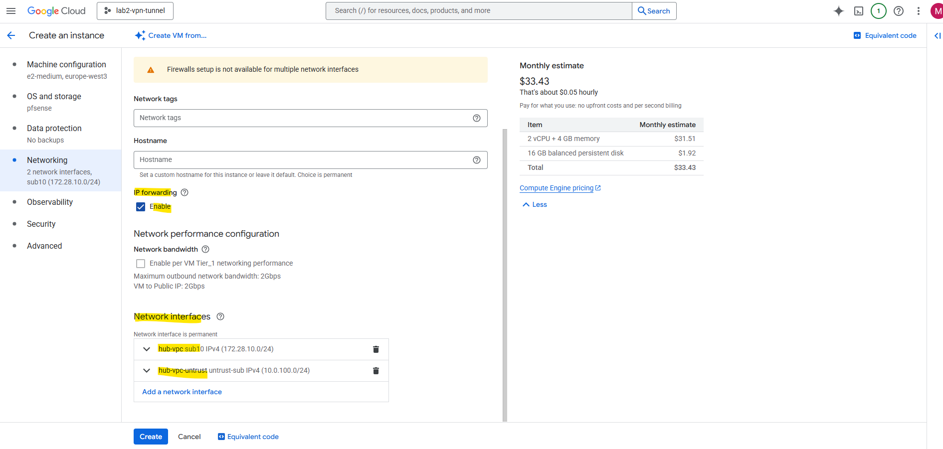
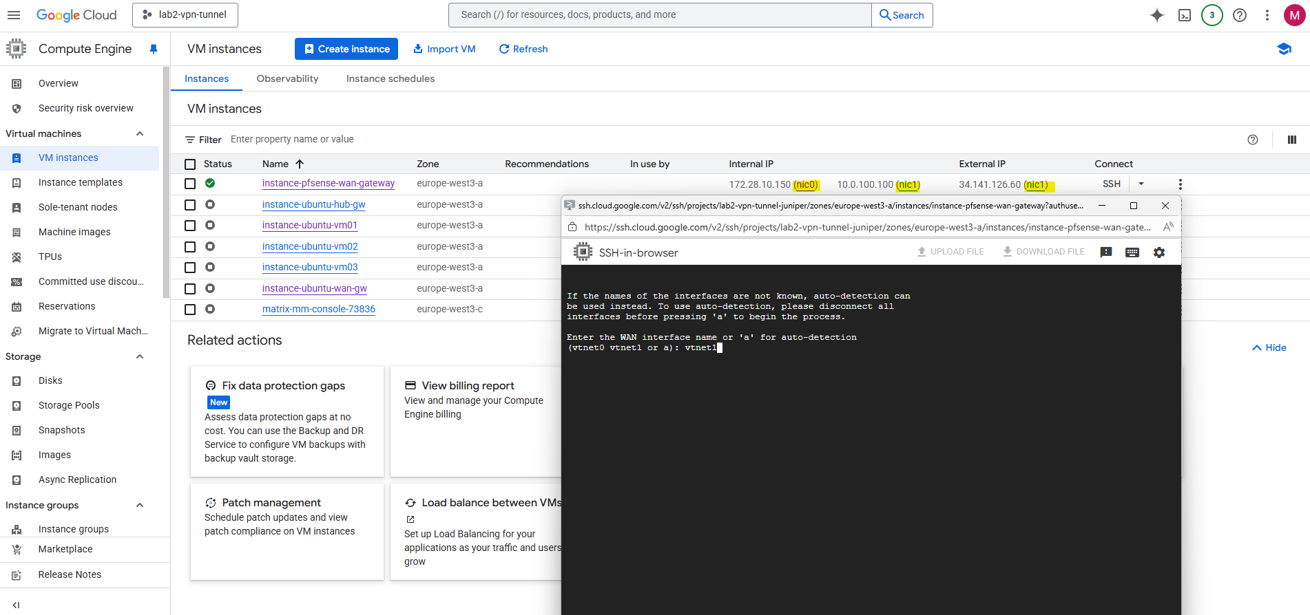
The NIC associated with the trusted Hub VPC will just have a custom internal private IPv4 address assigned to.
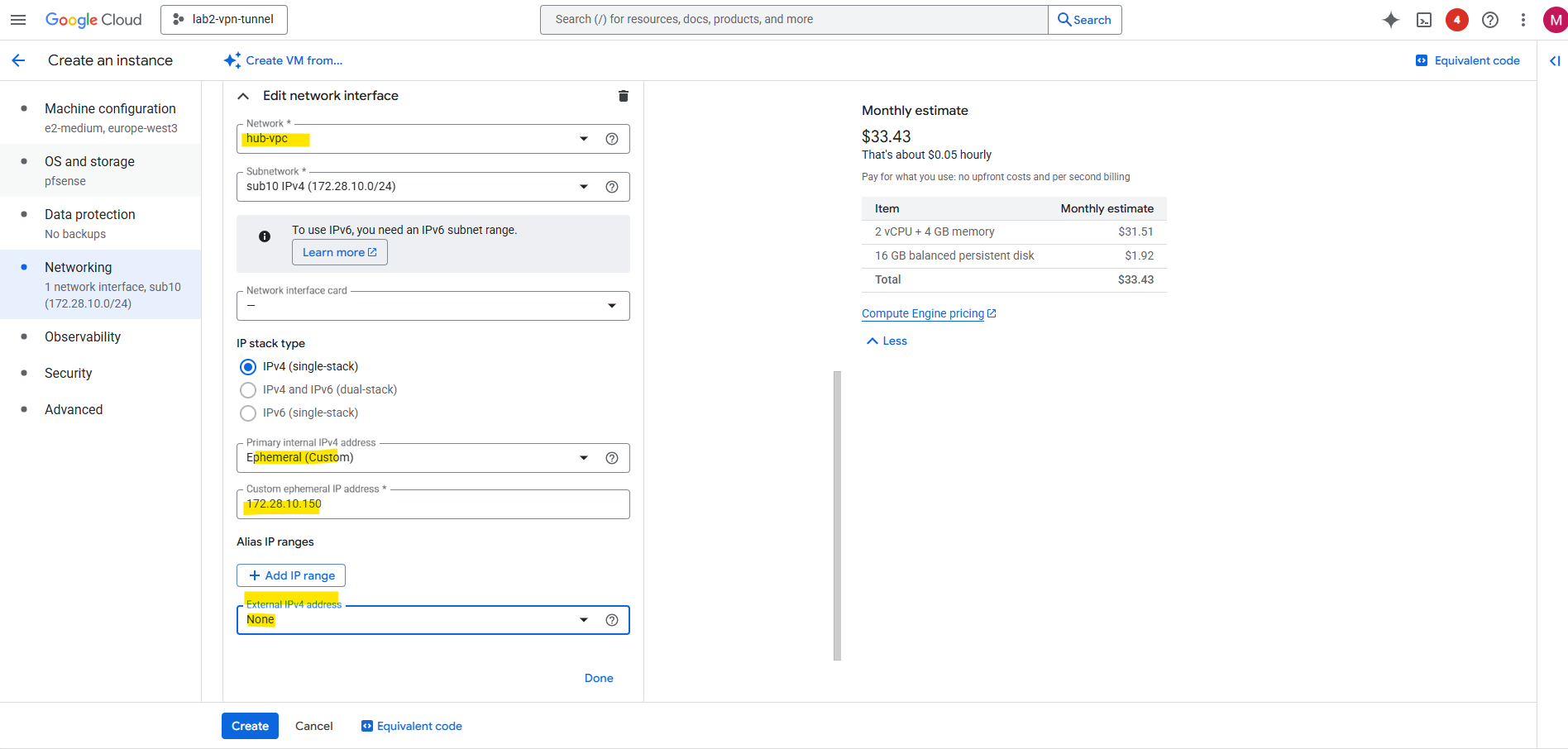
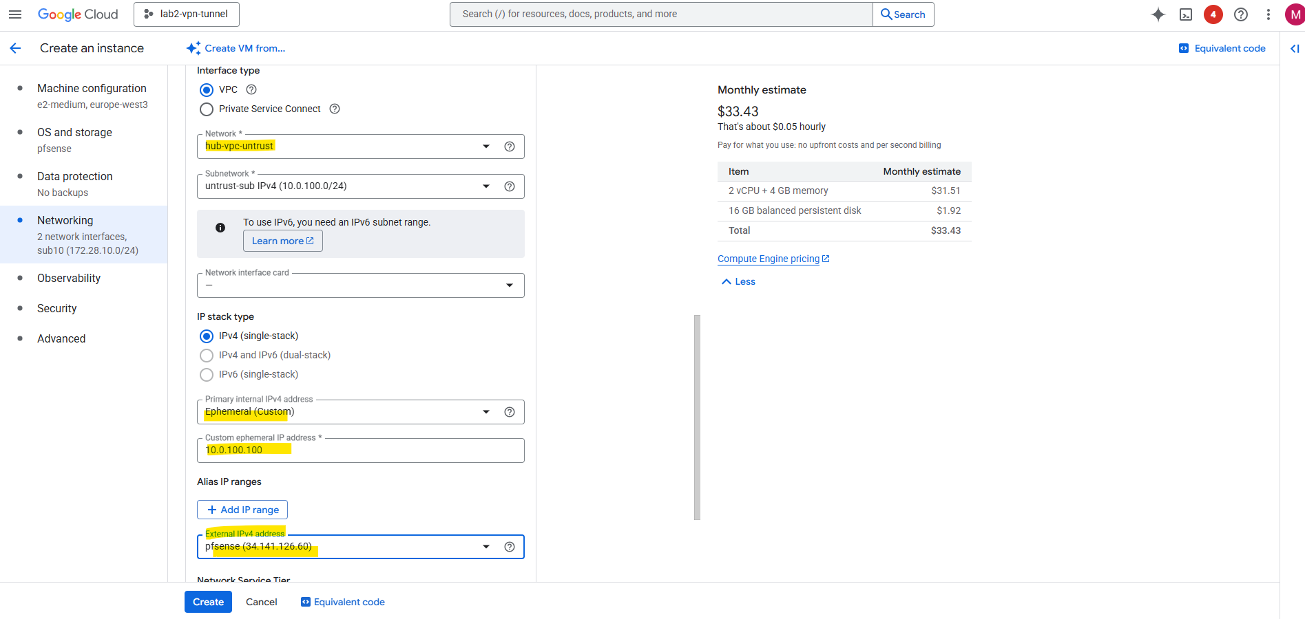
The NIC associated with the untrusted Hub VPC will also have assigned a external public IPv4 address for internet access. For the internal private IPv4 address I will use a custom IP address.
By assigning an external public IPv4 address to the second NIC (connected to the untrusted Hub VPC), pfSense can now send outbound traffic directly to the Internet through GCP’s default Internet gateway for the untrusted Hub VPC subnet (10.0.100.1).
In GCP, every VPC subnet automatically includes a default Internet gateway that provides a route to 0.0.0.0/0.
However, only VM instances with an external public IP address assigned to one of their interfaces can actually use this gateway to reach the Internet, all others remain isolated to internal traffic.
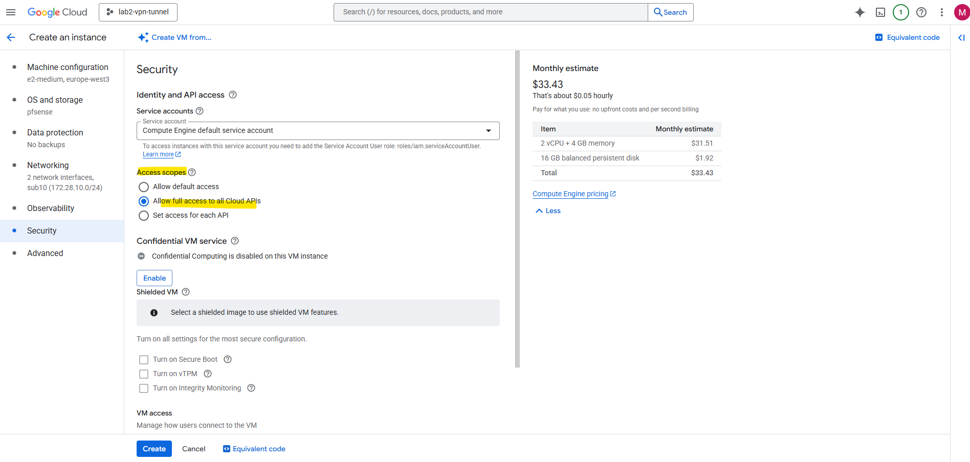
Allow access to the Cloud APIs and finally click on Create.
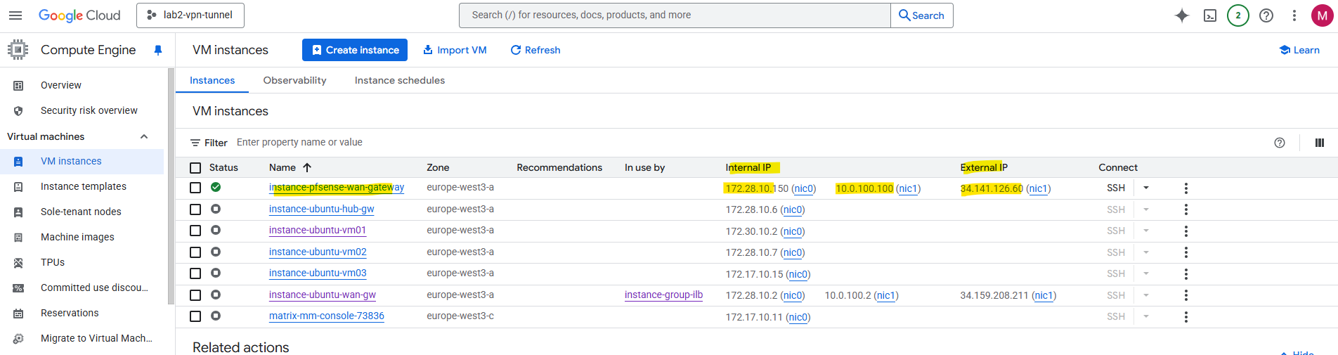
Click on the VM instance to enable the serial console to perform the initial configuration of pfSense.
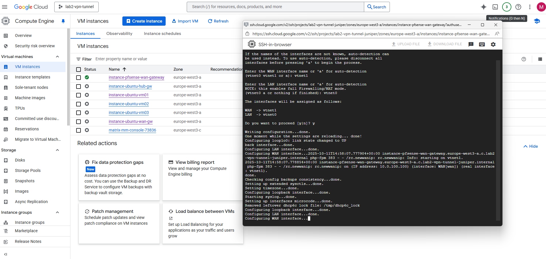
Connect to the serial console. We can already see pfSense’s configuration wizard. First we need to assign the network interfaces as usual.
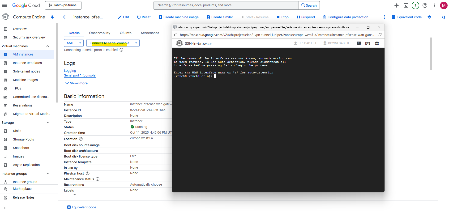
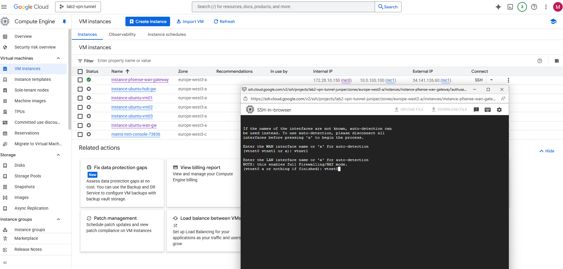
Select the WAN interface, in my case this is nic1 (in pfSense/FreeBSD this is vtnet0).
The LAN interface then is vtnet0.
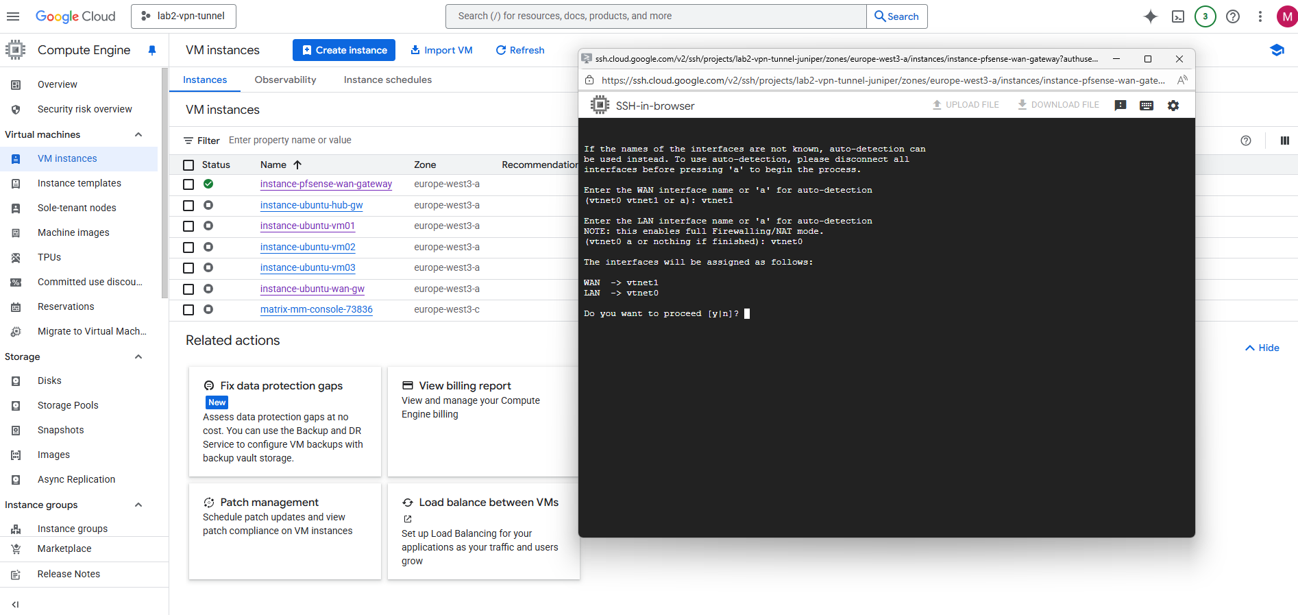
Confirm the network interface assignment.
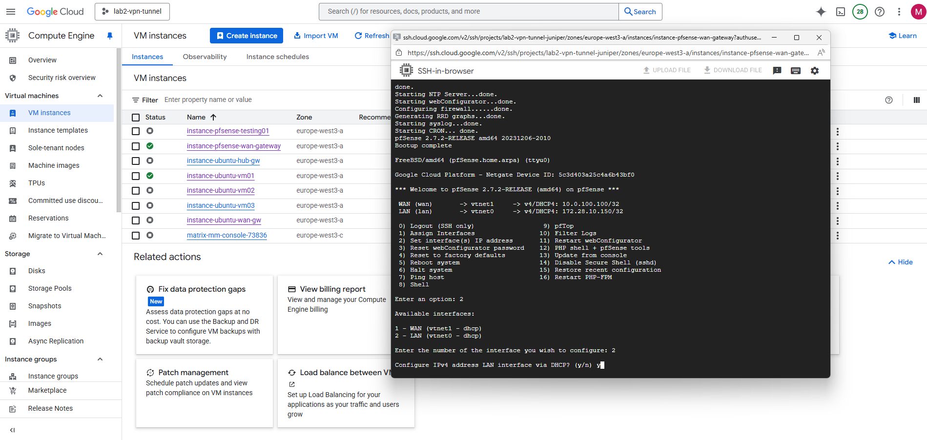
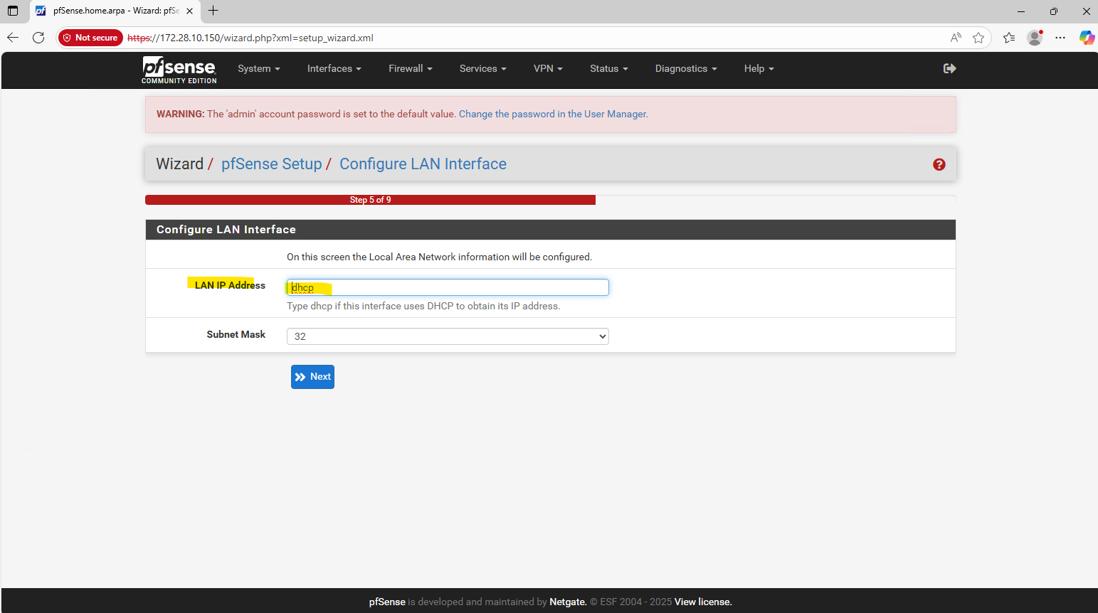
Next enter option 2 to set the network interfaces IP addresses.
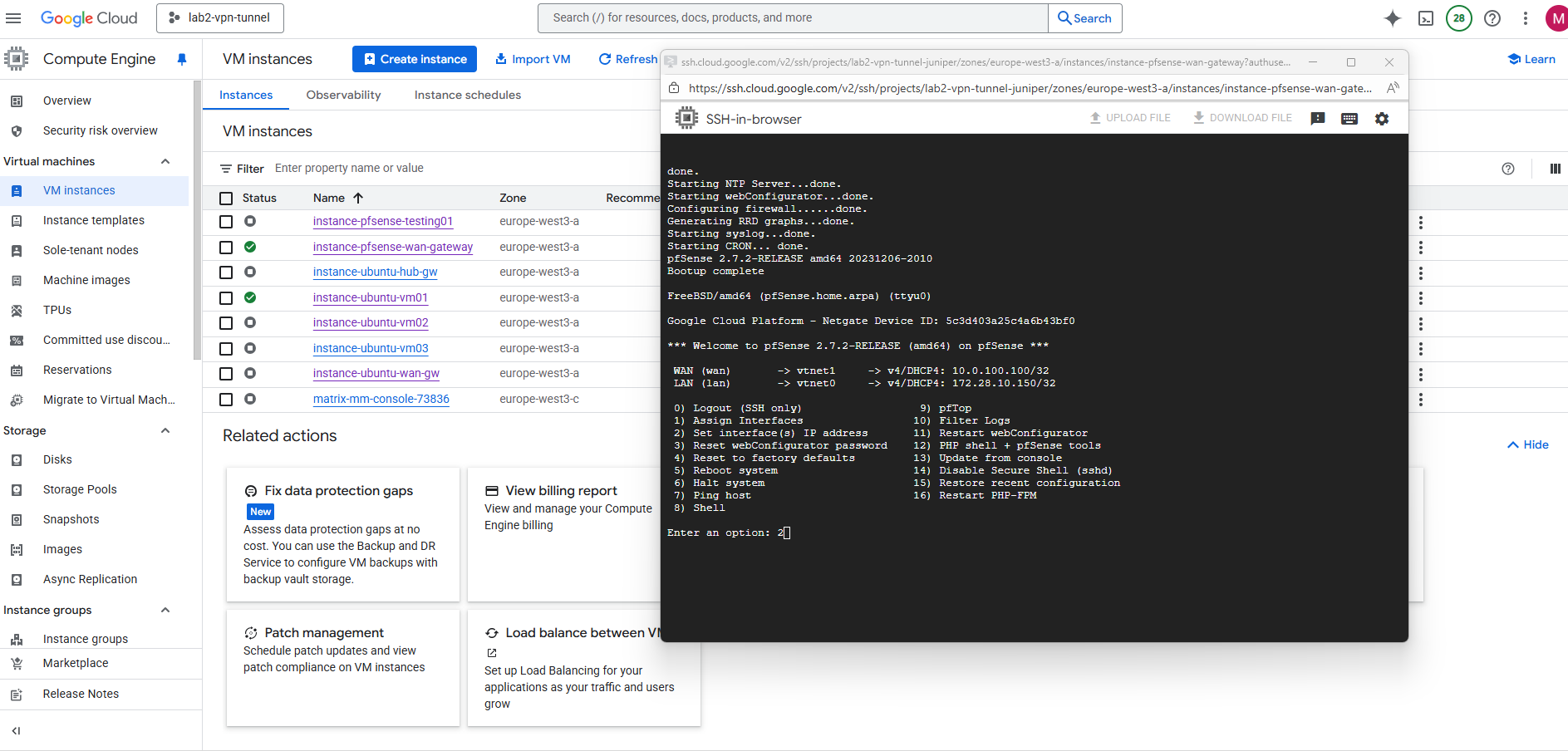
Select the interface you want to set the IP address for.

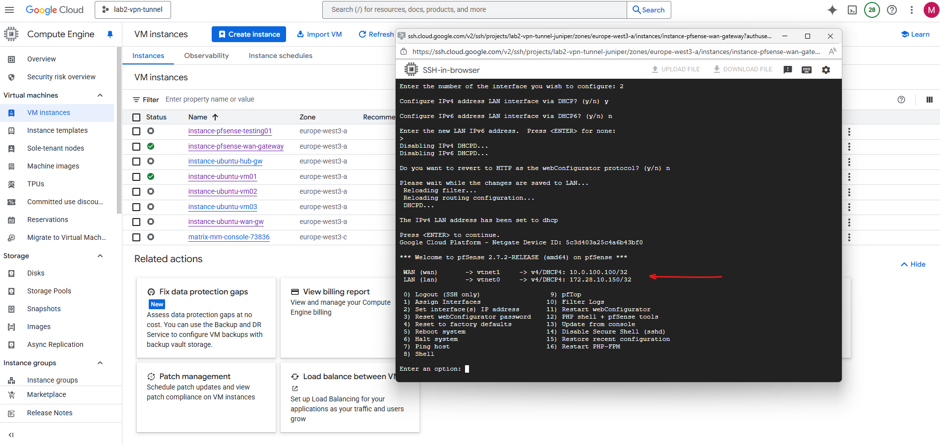
For Configure IPv4 address LAN or WAN interface via DHCP select for both Y.
For Google Cloud Platform (GCP) Virtual Machine (VM) instances, the best practice is not to manually assign a static IP address inside the operating system (OS), even if you are using a reserved static IP set via gcloud or the web console.
The network interface inside the VM’s OS should always be configured for DHCP.
GCP’s networking layer is responsible for assigning the internal IP address you specify (either ephemeral or a reserved static internal IP) to the VM’s network interface. The VM’s OS receives this IP address via the DHCP server run by Google Cloud’s VPC network.
Manually setting a static IP inside the guest OS can lead to an IP address conflict with the underlying GCP network management, especially if you change the network configuration (like the internal IP) in the GCP console or gcloud.
Finally both are configured via DHCP.
Spin up the Production pfSense VM instance (by using a Custom Image)
Even we can finally use both, either a snapshot or a custom image as the boot disk for creating a new VM instance in GCP, they behave differently behind the scenes.
Snapshots are disk-level backups bound to a project, while images are flattened, shareable templates meant for consistent multi-project or multi-region deployments.
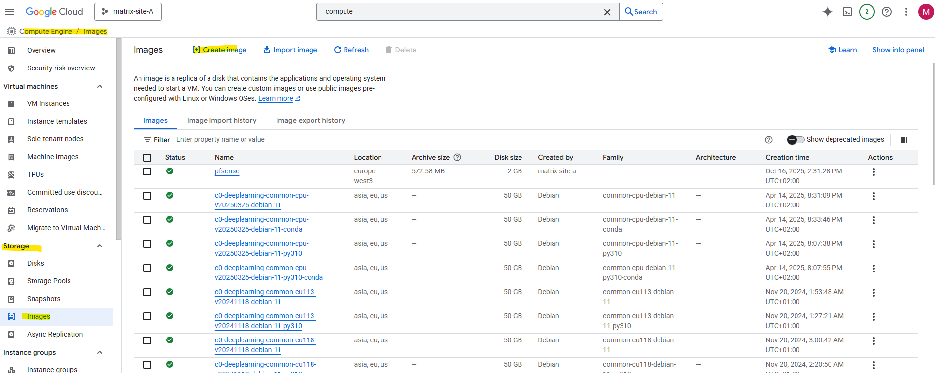
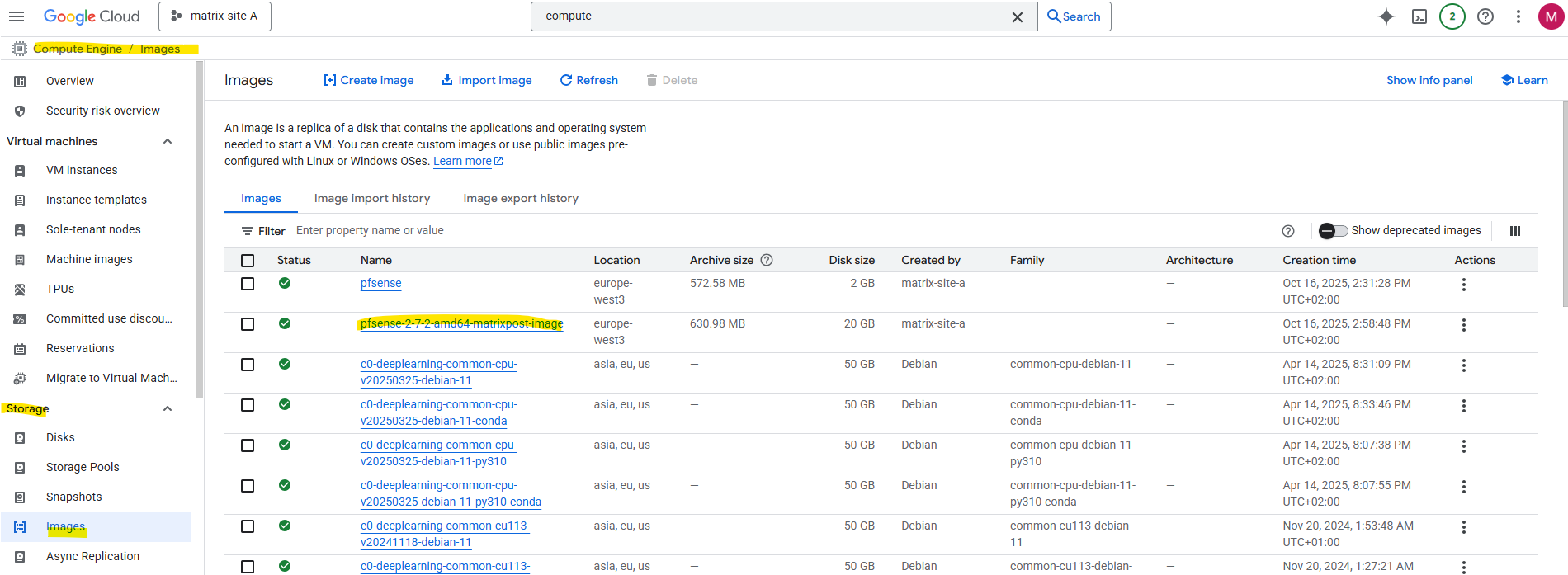
To create a custom image from our previous pfSense installation we take a snapshot (screenshot below) from the disk we used for the installation, navigate to Compute Engine → Images.
Click on + Create Image.
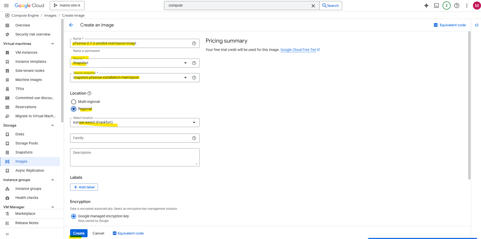
Enter a name for the new image, for the source this time we need to select Snapshot and for the Source snapshot select our previously created snapshot.
Click on Create.
Now we have a reusable, standalone template optimized for deploying new instances across projects or regions.
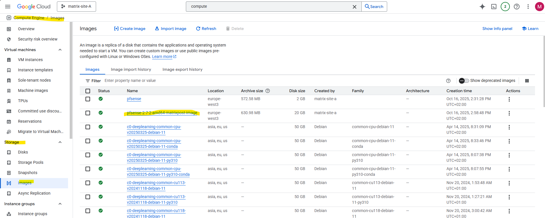
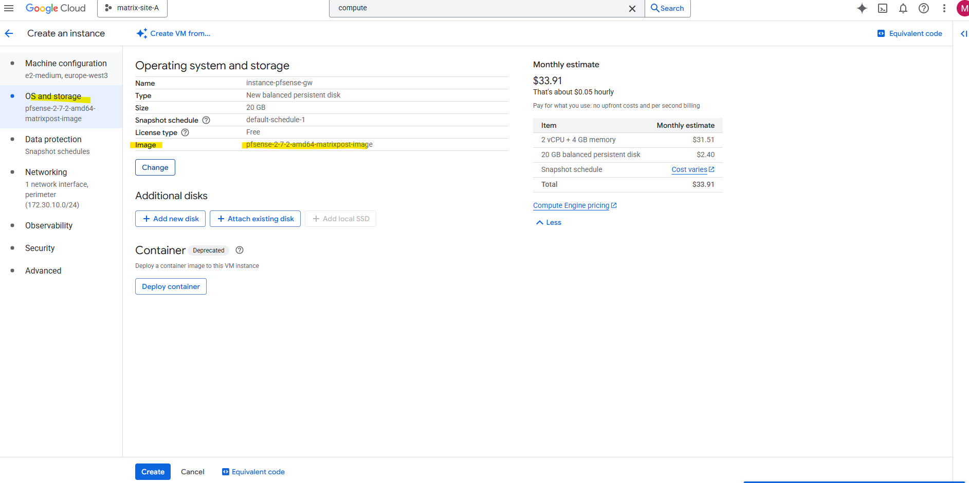
When creating a new VM instance, we can now use this new custom pfSense image.
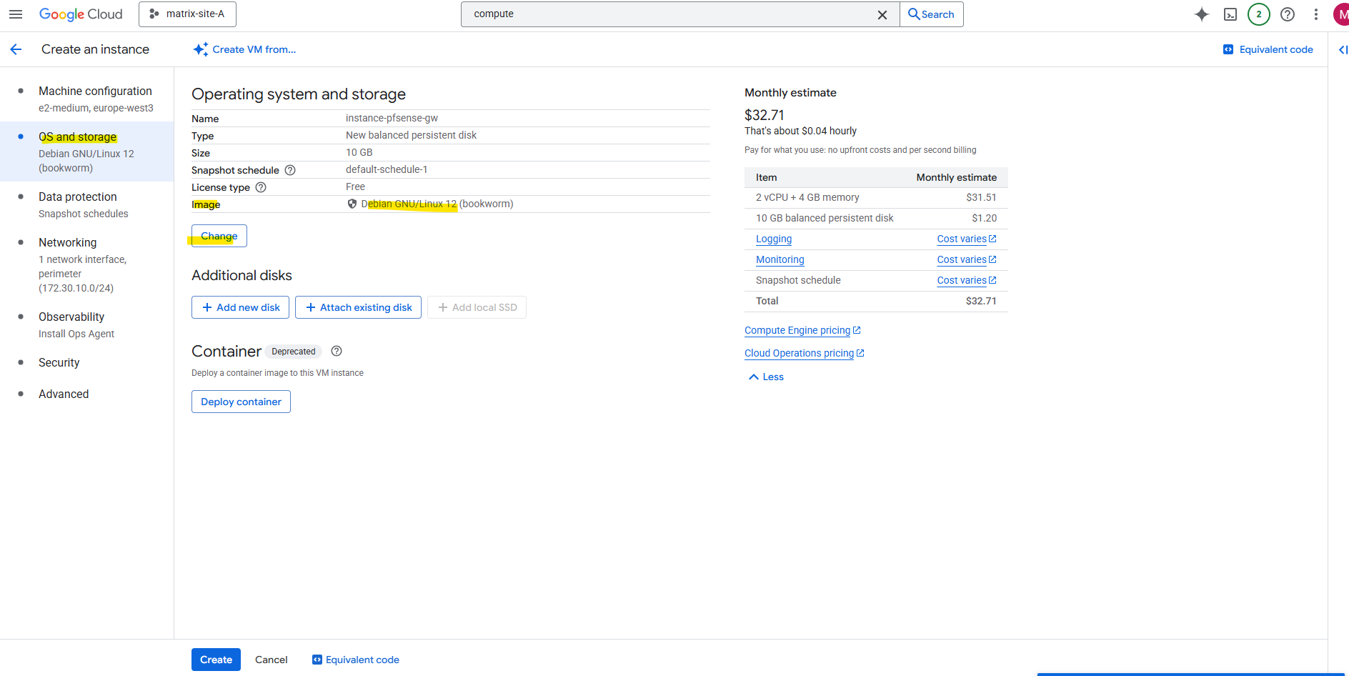
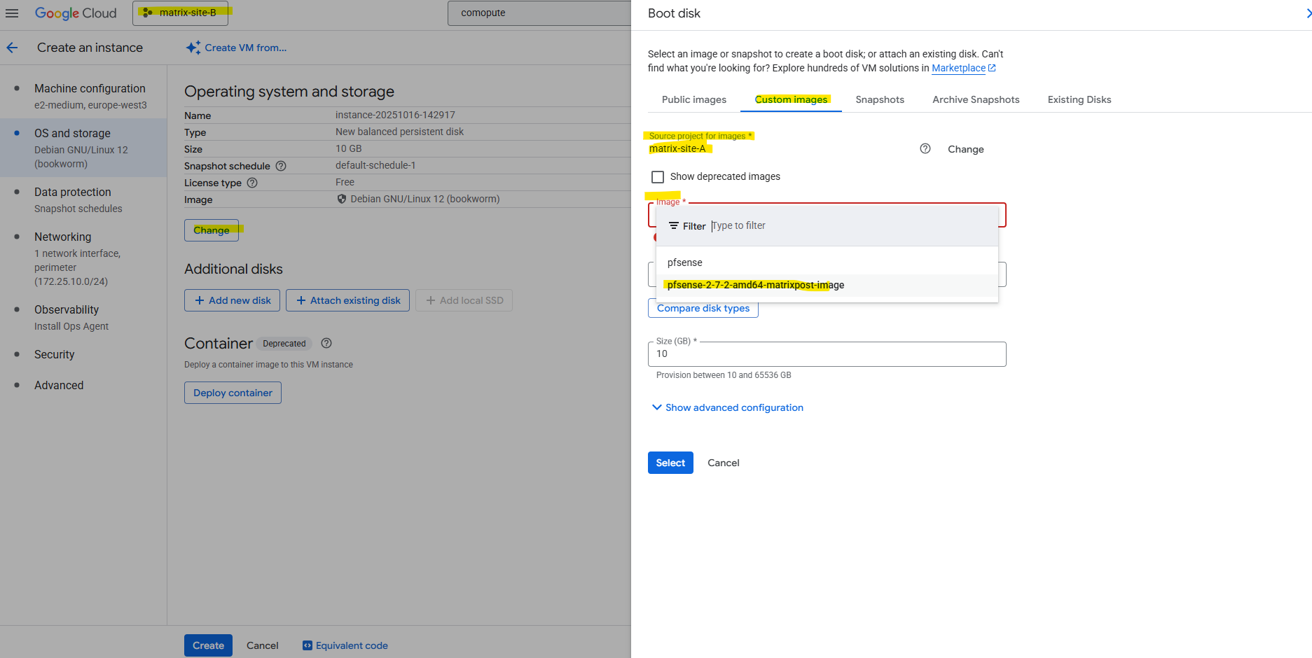
Under OS and storage click on Change to select our newly created custom pfSense image.
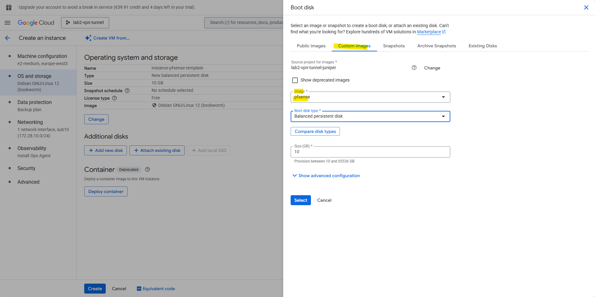
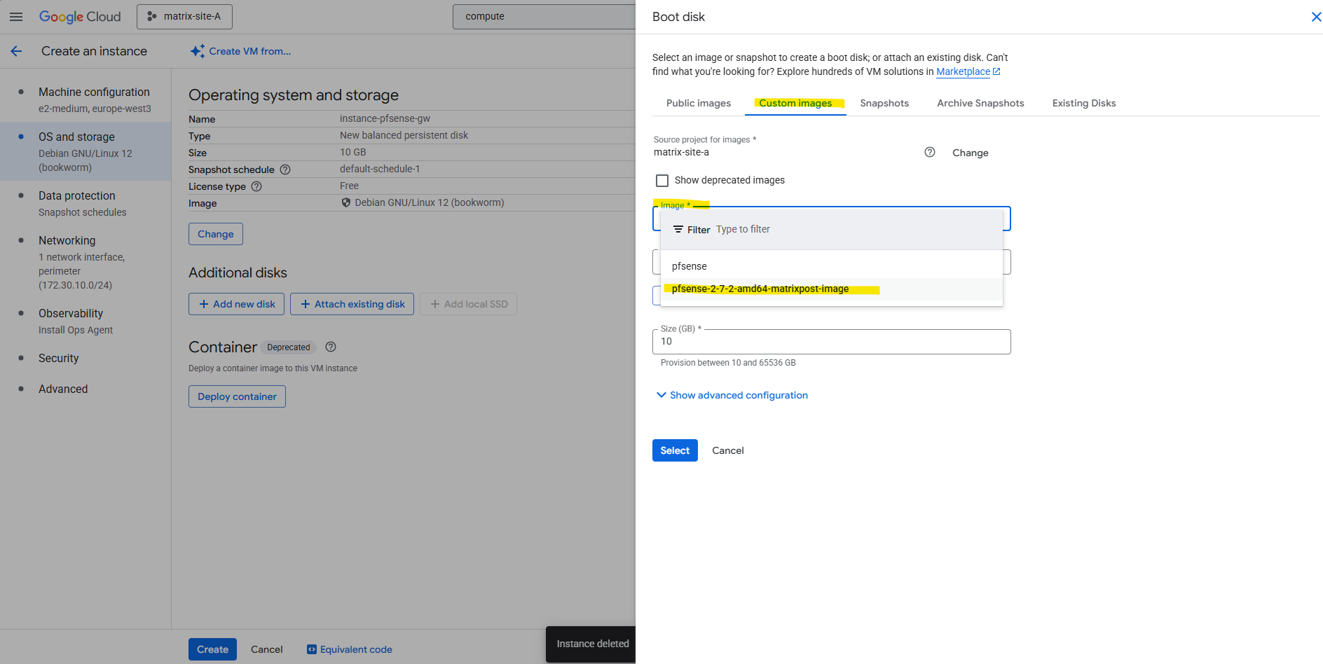
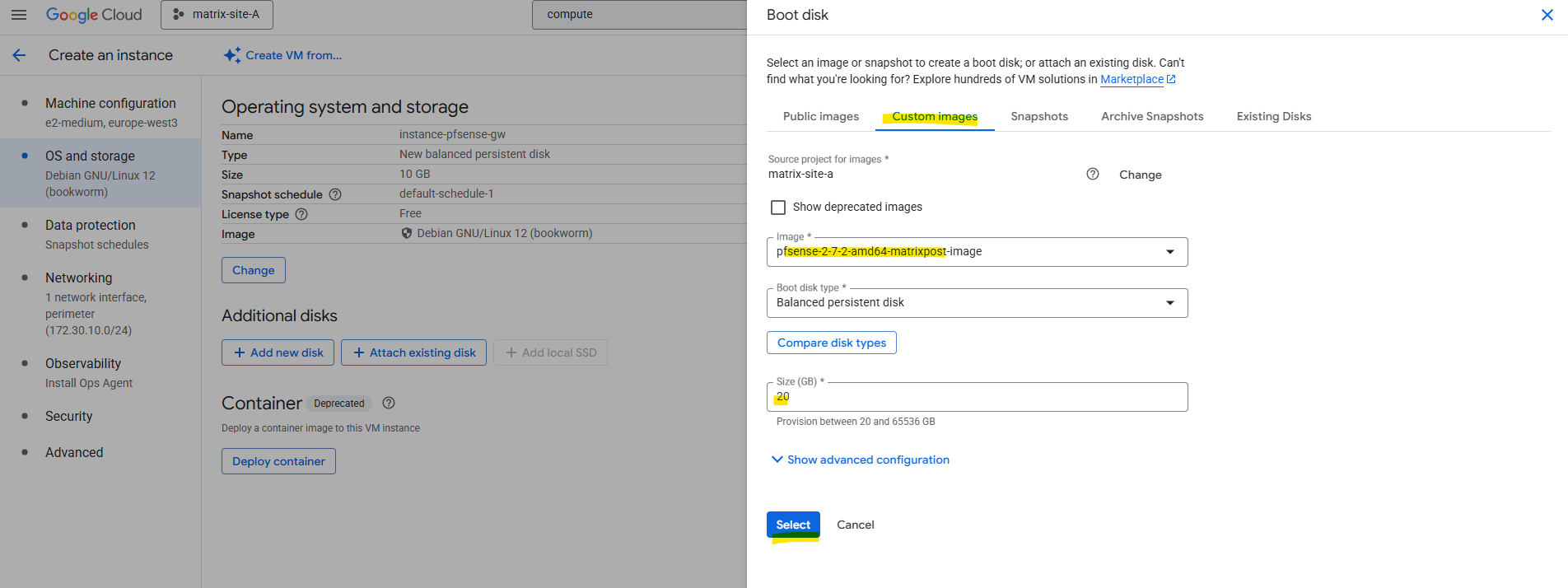
Switch to the Custom images tab and select our custom pfSense image.
Take care to not accidentally select the first created pfSense image (actually just the pfSense installer disk – like mounting an ISO in a hypervisor) .
Click on Select.
Sharing the Image between Projects in the same Organization
When working with multi-project setups in GCP, it’s often useful to reuse a custom VM image across several environments instead of rebuilding it each time.
Google Cloud lets you easily share images between projects within the same organization or billing account by assigning the proper IAM role (Compute Image User) to the target project.
This way, other projects can directly deploy new instances from the shared image without duplicating storage or creating separate copies.
Below I want to share the highliged custom pfSense image in project named matrix-site-A to other projects (matrix-site-B) in my organization.
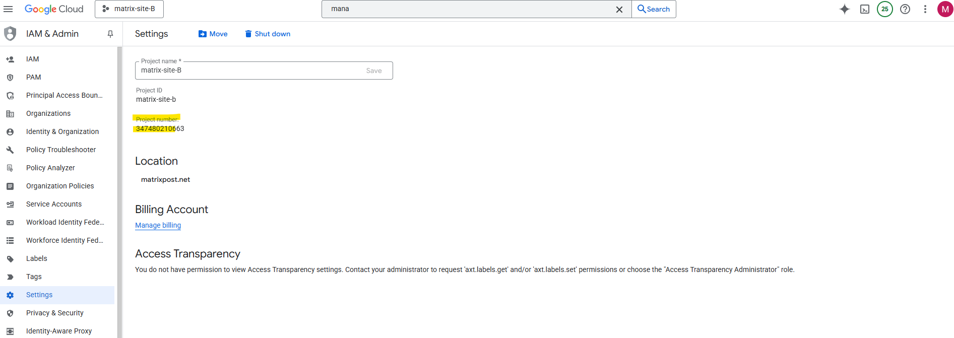
To enable sharing we first need to note the project number of the project from which we want to access our custom image created in a different project. In my case, I also want to access the custom image created in project named matrix-site-A also from my project named matrix-site-B.
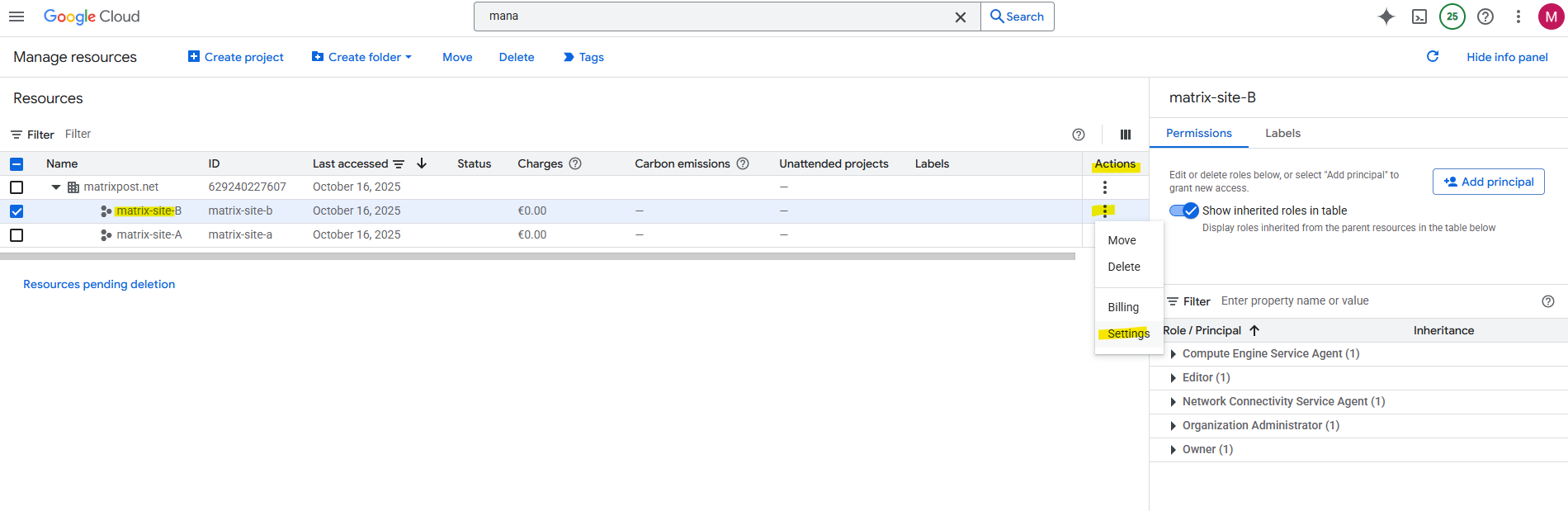
Note the project number.
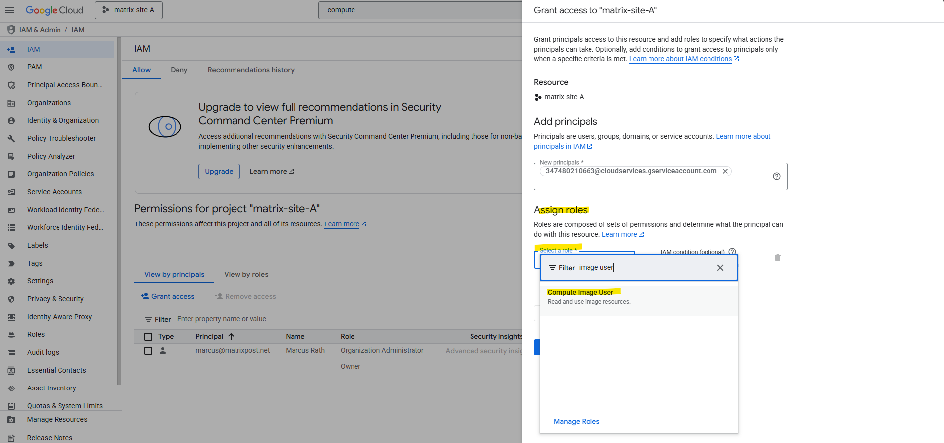
On my project (matrix-site-A) where the custom image was created and is stored, we now need to add the email address of the Google APIs service account from the project we want to allow access to
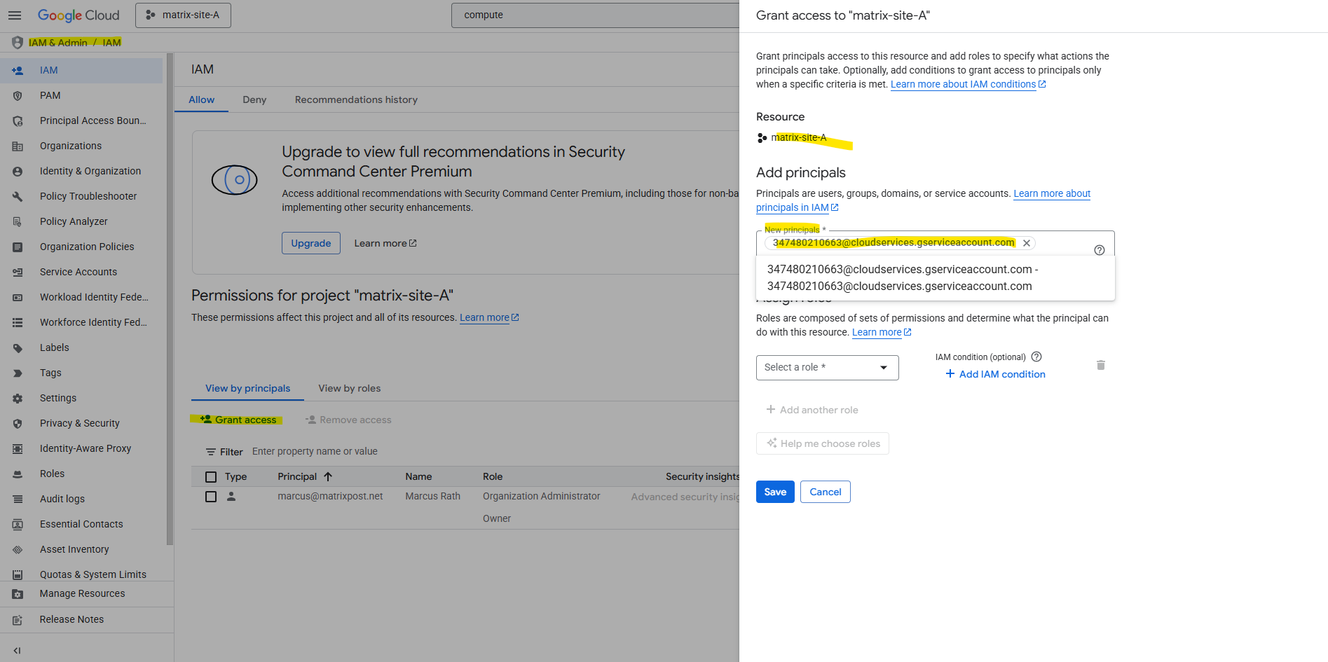
Next we need to assign the Compute Image User role to the service account. Click on Save.
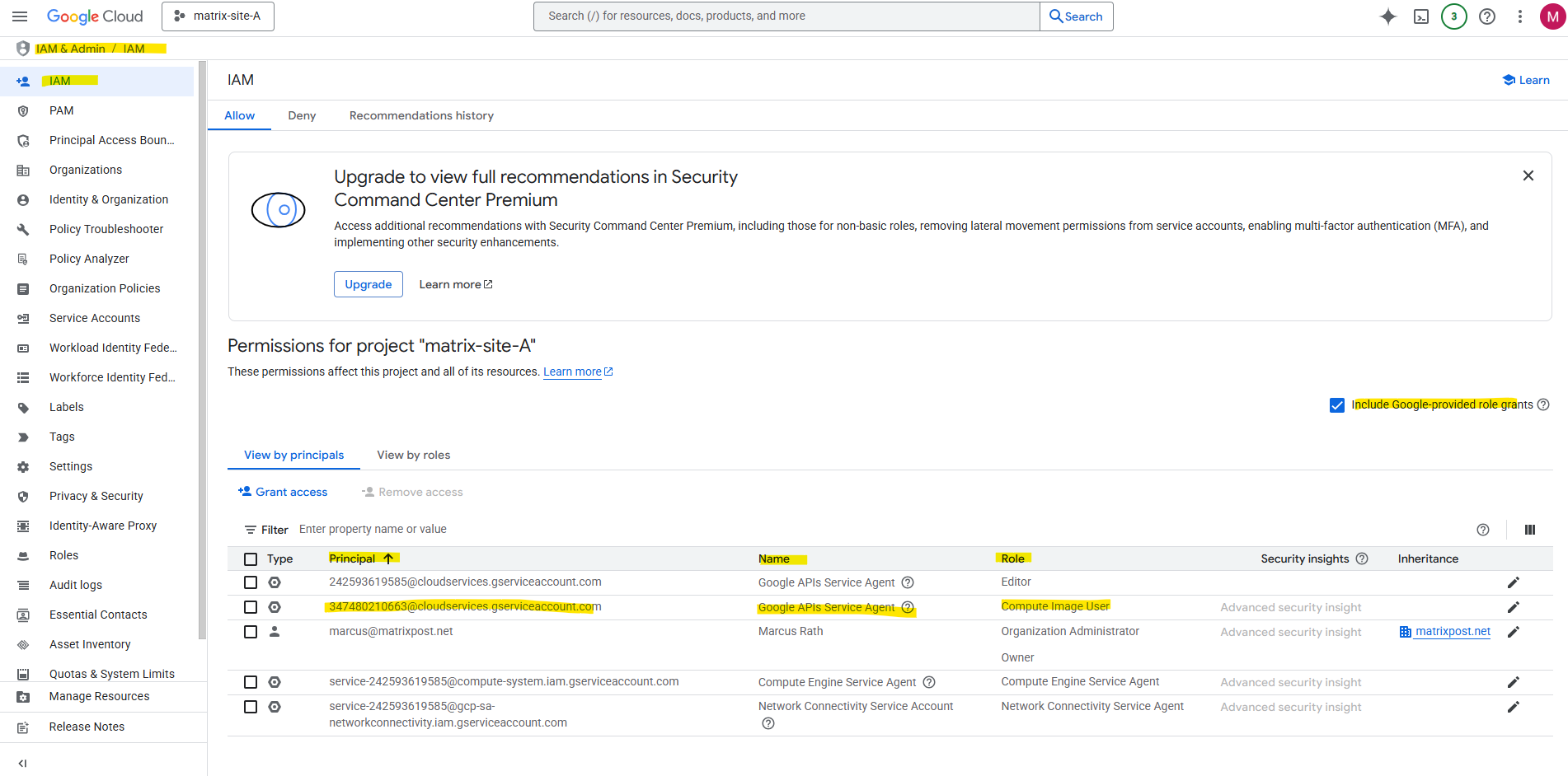
By checking Include Google-provided role grants we will also later see our newly assigned role to the service account named the Google APIs Service Agent from our other project named matrix-site-B.
More about different types of service accounts in GCP you will find here https://cloud.google.com/iam/docs/service-account-types.
The user in our different target project (in my case matrix-site-B) can now create a new instance from the shared image by selecting the image from the correct project (in my case matrix-site-A) in the Google Cloud console.
By default the home project is selected, click on Change.
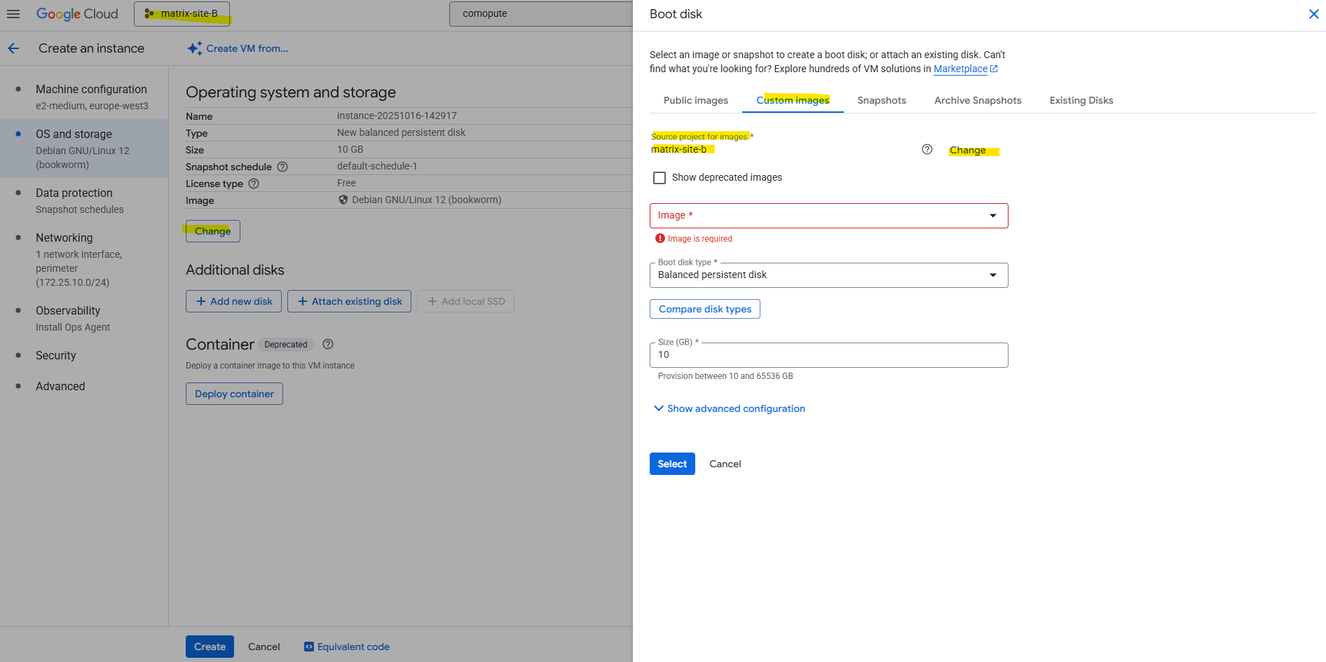
Select the project where our custom pfSense image was created.
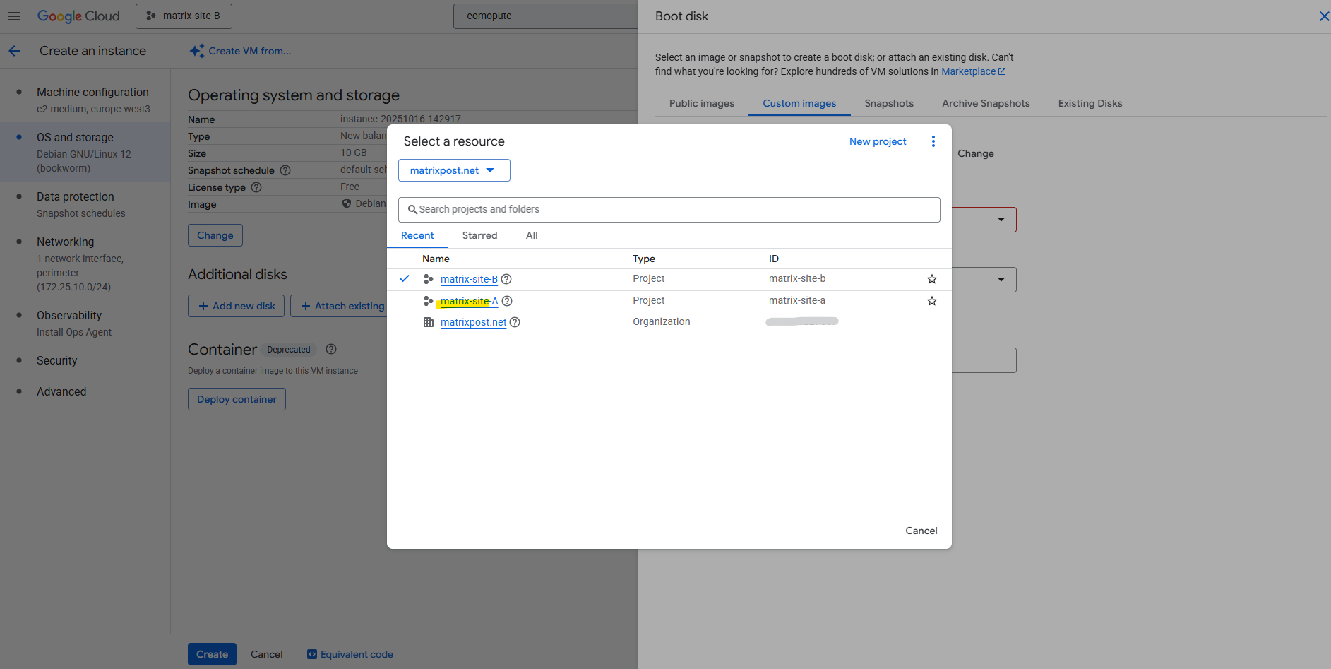
After switching the project our previously created custom pfSense image in our other project should be available to select below. The rest as usual.
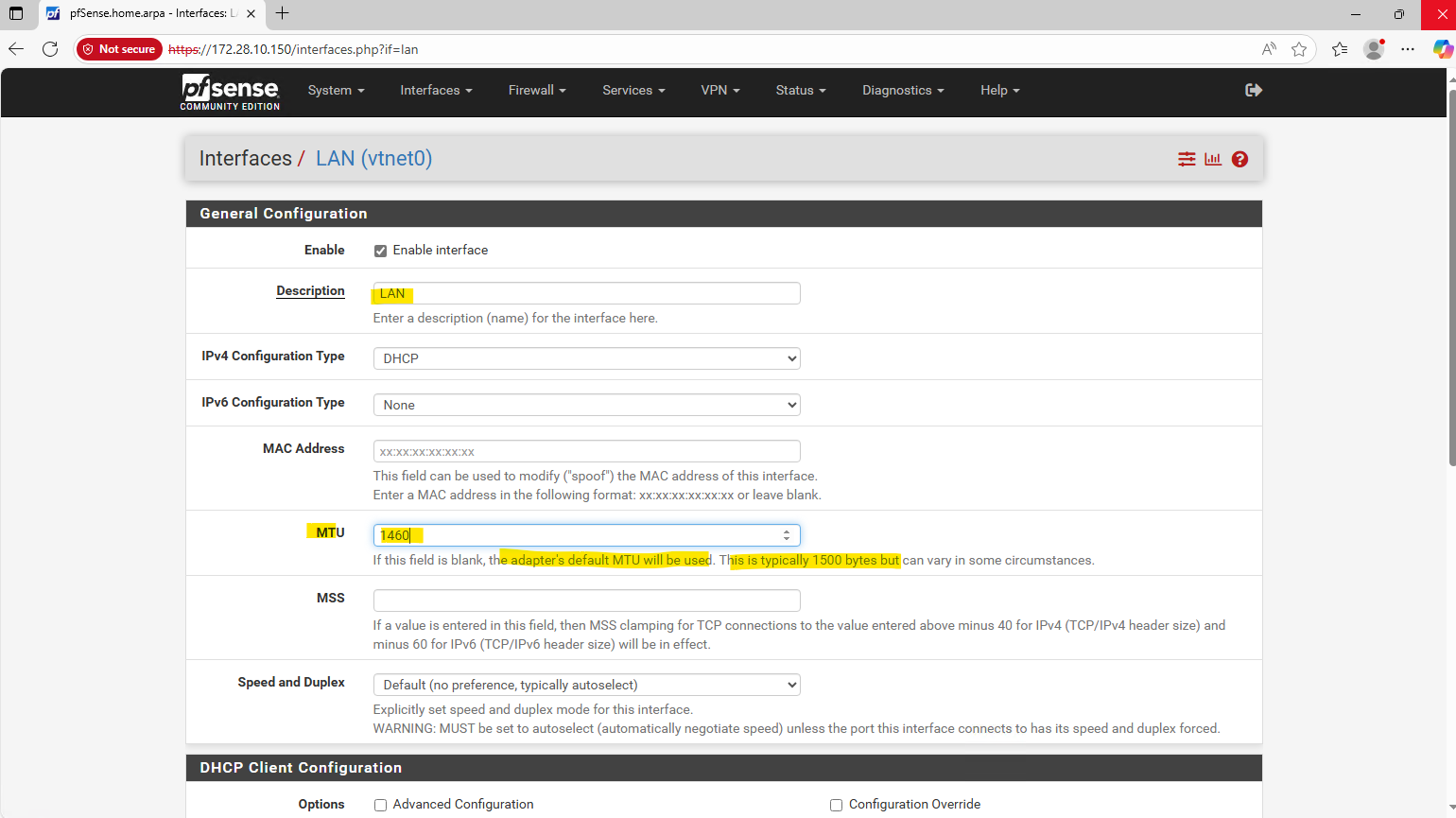
Adjusting the MTU in pfSense to Match Google Cloud’s Network Fabric
Google Cloud VPCs use an MTU of 1460 bytes by default, although higher values such as 1500 can be configured.
On most Linux distributions we can check the MTU set for the NICs by running the commands below. For FreeBSD we can use ifconfig.
$ ip addr show
or
$ ip link
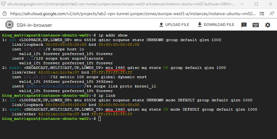
When pfSense (running on FreeBSD) keeps its default MTU of 1500 while the VPC operates at 1460, network traffic will fail entirely due to packet handling inconsistencies in the VirtIO (vtnet) driver.
This issue seems to be solved in pfsense 2.8 and later (using FreeBSD 15) and can still be left on its default settings (MTU 1500)
Setting the pfSense interface MTU to 1460 ensures that packets conform to Google Cloud’s VPC limits and is required for network connectivity to function correctly in this environment.
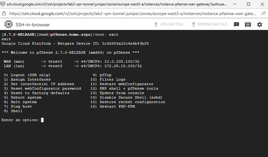
So enter the pfSense shell to adjust the MTU to 1460.
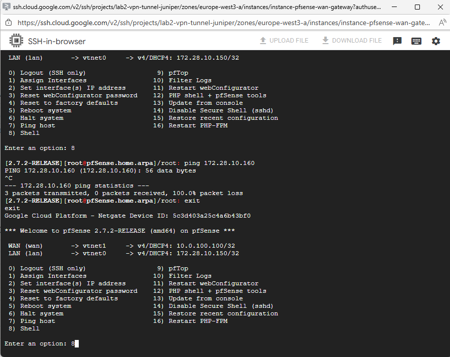
We can first check the actual MTU by running the ifconfig command.
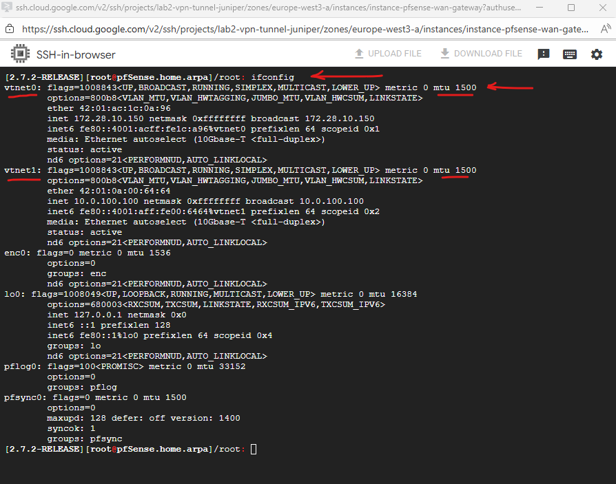
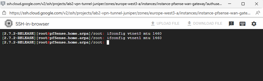
To adjust the MTU to 1440 for both interfaces (LAN + WAN), run:
To change these MTU values persistantly, we will later use the WebUI where we can set the MTU directly under Interfaces.
ifconfig vtnet0 mtu 1460
ifconfig vtnet1 mtu 1460
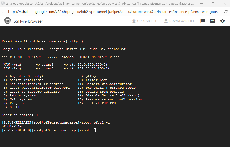
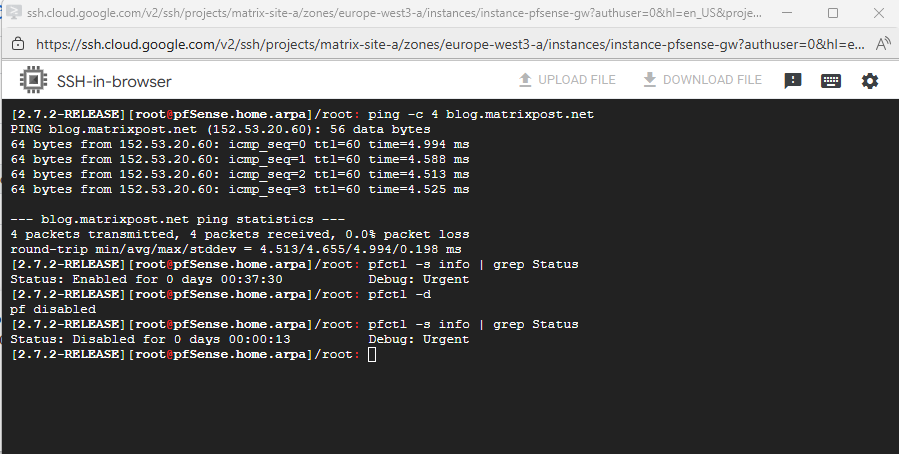
To test if we can ping our pfSense already successfully, we need to temporary disable the firewall.
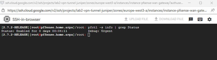
We can first check the current state by running.
pfctl -s info | grep Status
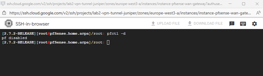
To disable it run.
pfctl -d

To re-enable it run
pfctl -e
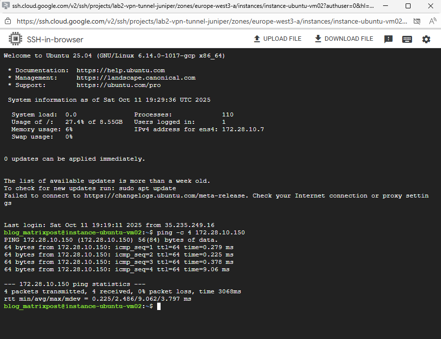
Looks good and I am able to ping the pfSense VM already on its LAN interface and IP.
We also need to allow inbound ICMP traffic on the corresponding VPC firewall (trusted Hub VPC in my case).
Next we can do the final configuration of pfSense by using the web console.
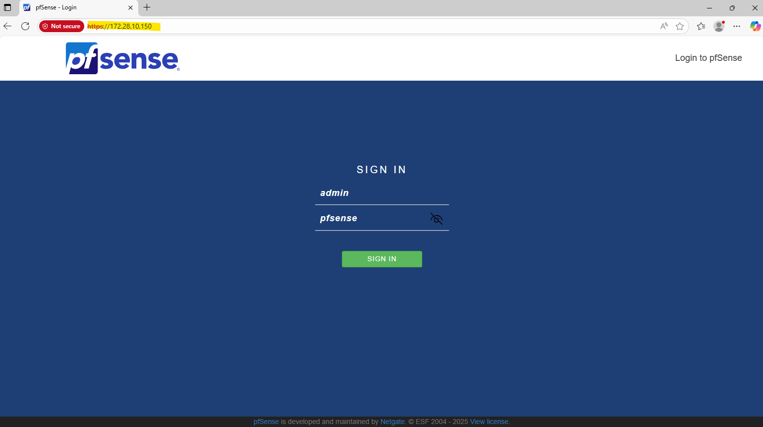
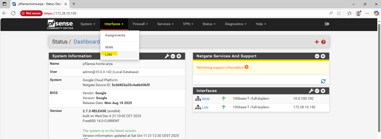
pfSense Configuration (Web UI)
I will finally access the pfSense Web UI from a Windows VM running in my on-prem vSphere lab environment and connected through a HA VPN tunnel with GCP.
The default admin password is pfsense.
I will use Google’s DNS Server for name resolution.
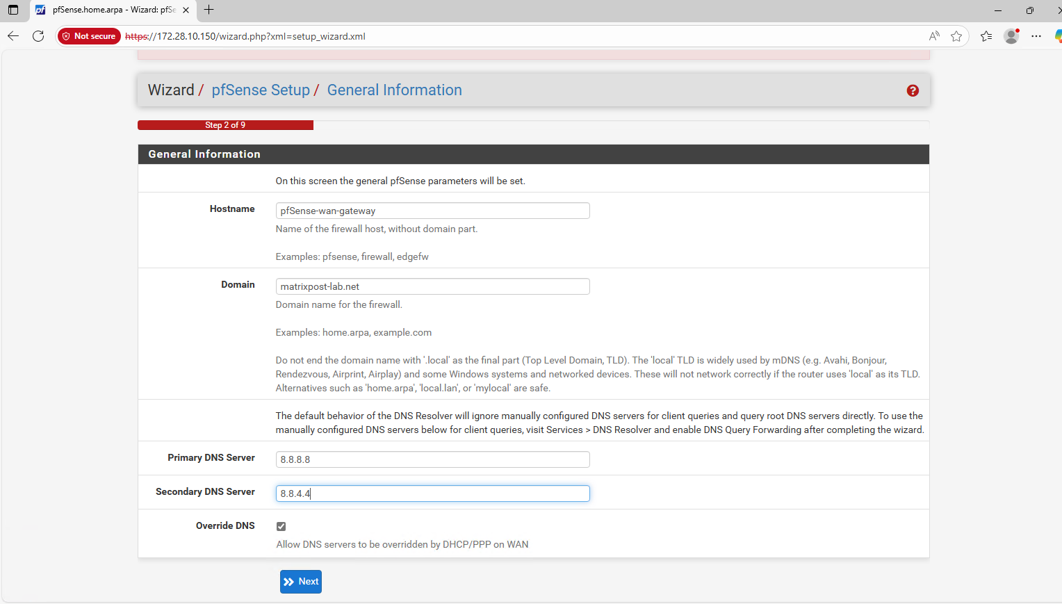
As already set and mentioned, in GCP we should use inside the guest OS usually DHCP.
For Google Cloud Platform (GCP) Virtual Machine (VM) instances, the best practice is not to manually assign a static IP address inside the operating system (OS), even if you are using a reserved static IP set via gcloud or the web console.
GCP’s networking layer is responsible for assigning the internal IP address you specify (either ephemeral or a reserved static internal IP) to the VM’s network interface. The VM’s OS receives this IP address via the DHCP server run by Google Cloud’s VPC network.
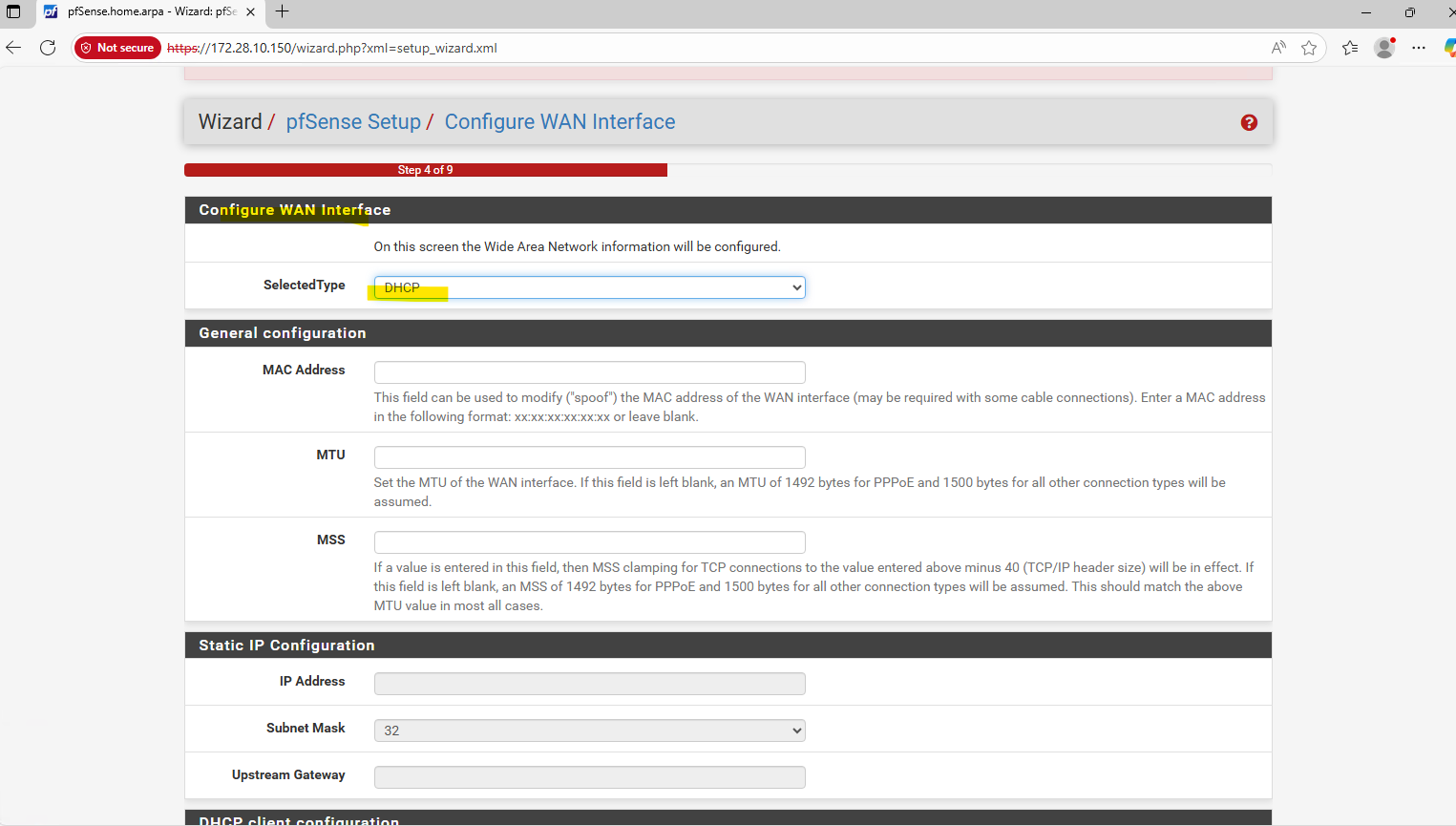
Outbound internet is also already working because we set DHCP for the WAN interface, the external public IPv4 address assigned in the GCP web console will allow to use the default internet gateway for the untrusted Hub VPC as mentioned further above.
That outbound internet access is working we can see in pfSense already because it is able to determine the available latest version.
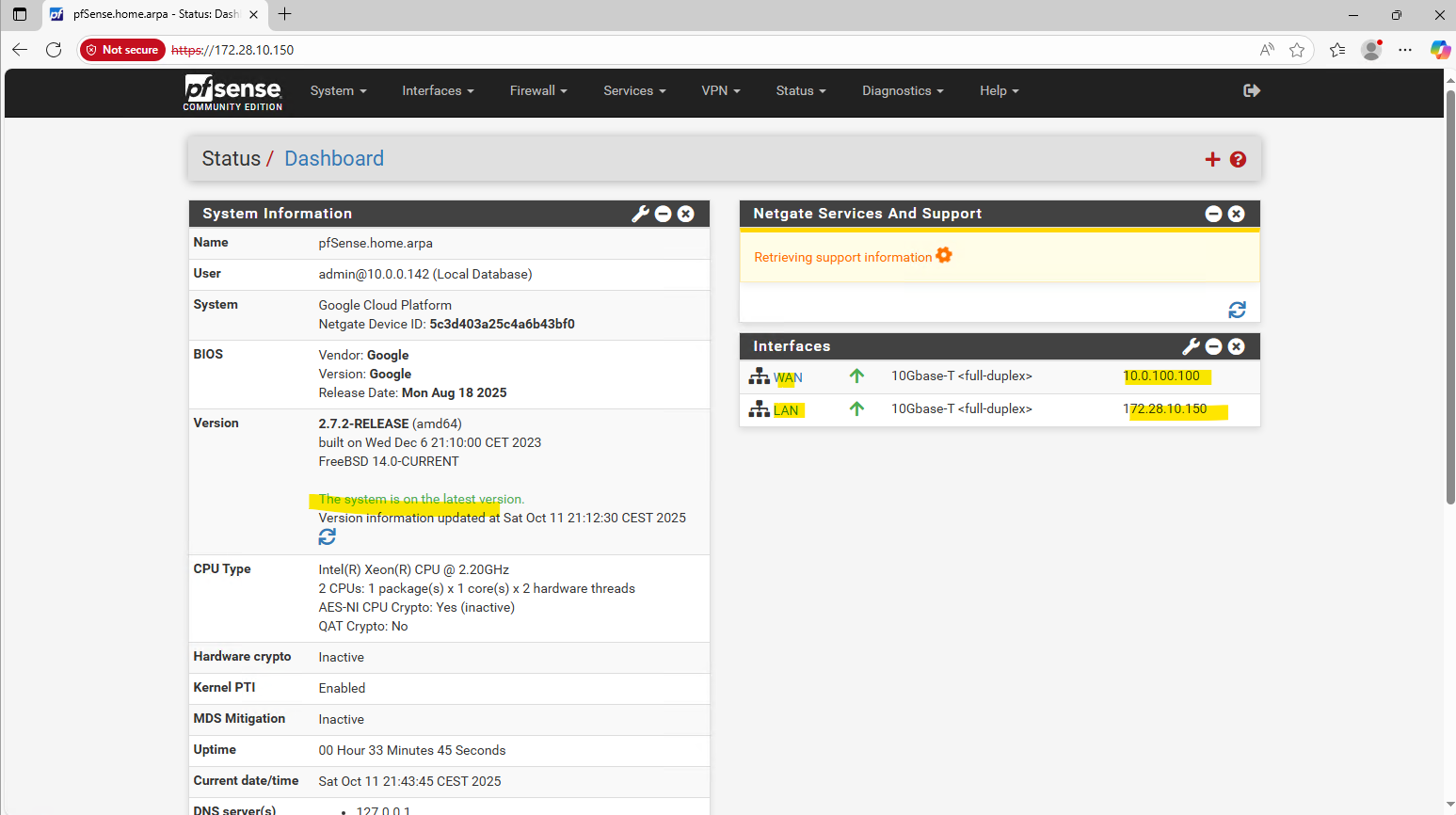
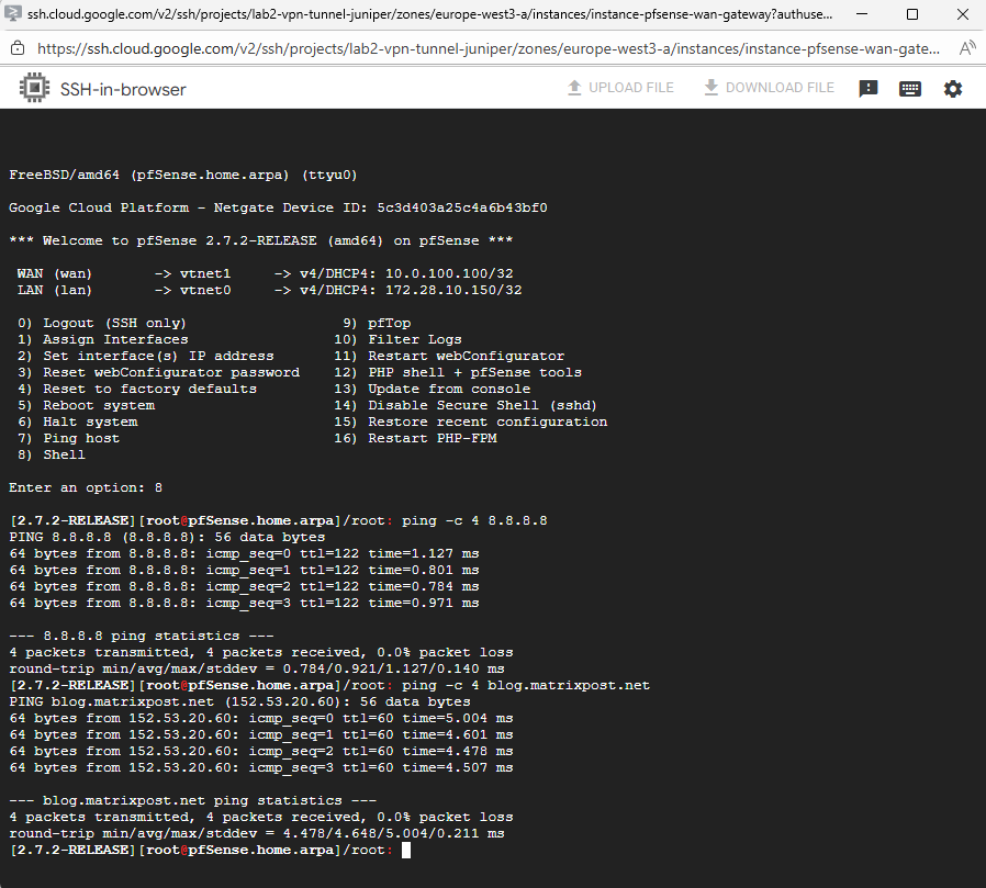
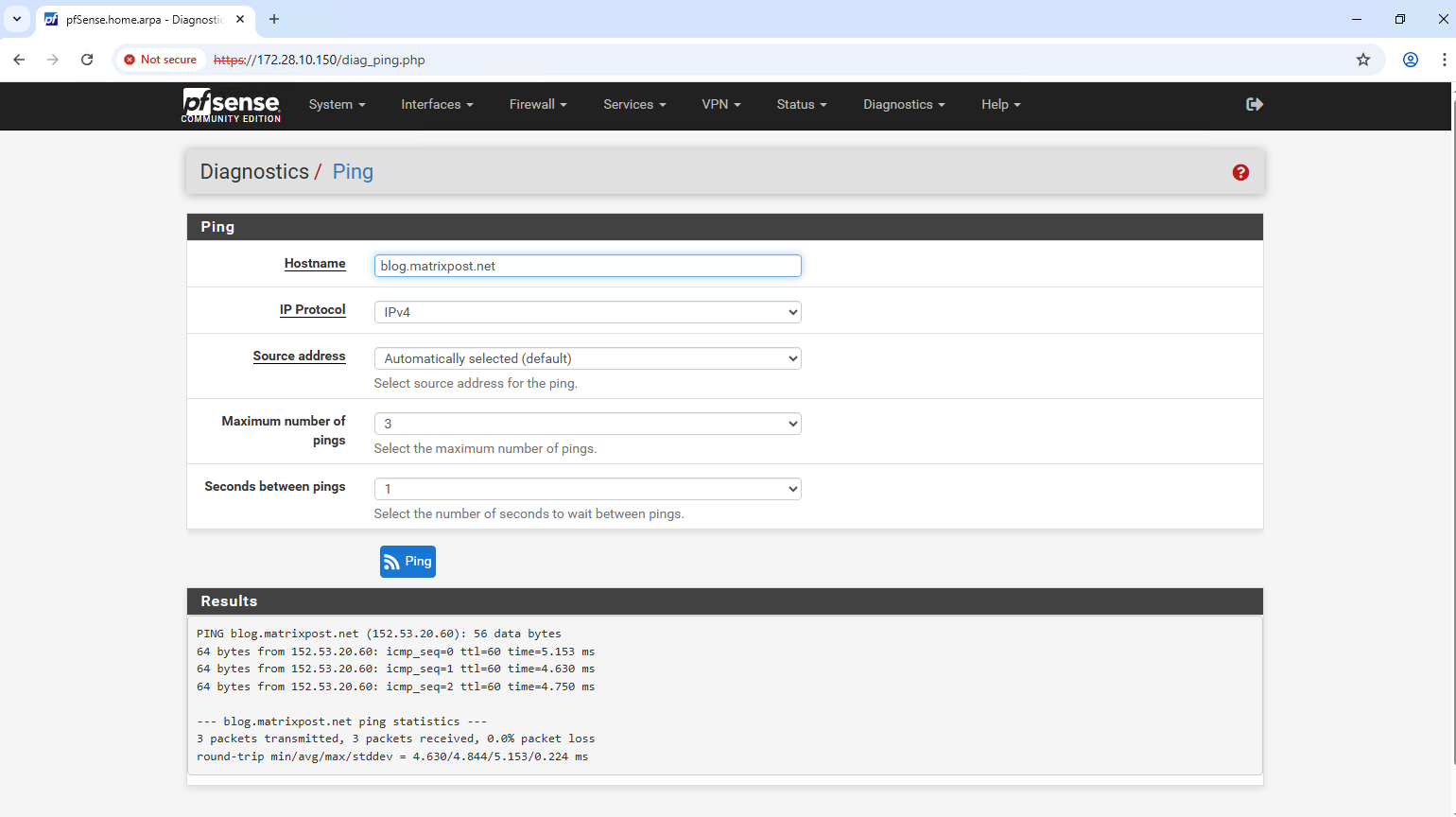
Further we can also check internet access either directly from the shell or the diagnostic utilities in the Web UI.
By using the Web UI under Diagnostics -> Ping.
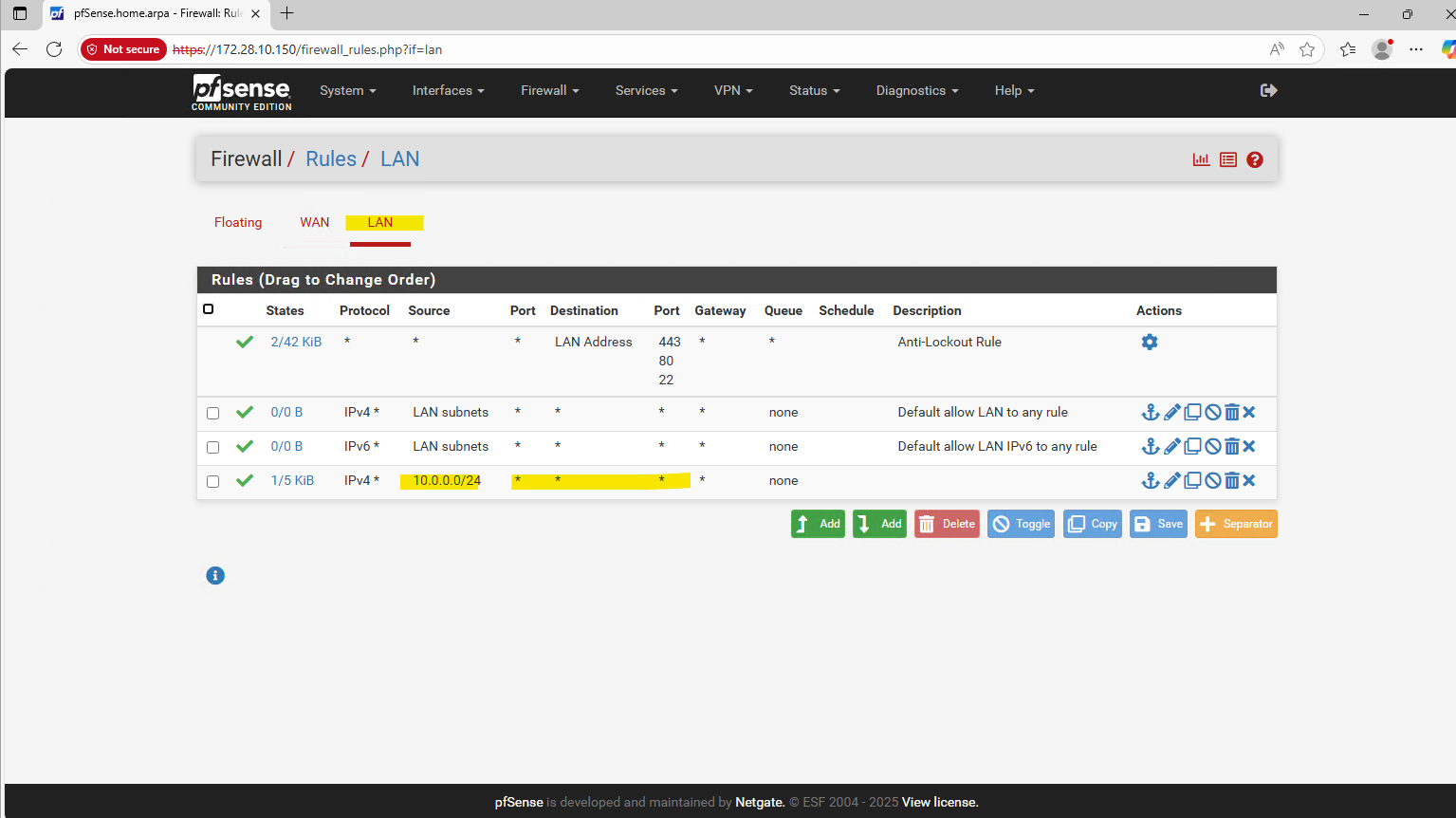
We will now first allow ICMP and web traffic for the subnet we will use to access the Web UI. So far the firewall is still disable (pfctl -d command we run previously), but when changing e.g. the MTU to make it persistent, after saving the changes the firewall would be automatically enabled again and we may will lost access depending from which source we access the Web UI.
By default access from the LAN subnets is allowed already, in my case I need to add my on-prem network which I will use to access the Web UI.
Next I will set the MTU for both network interfaces to 1460 (instead its default 1500) as further above mentioned.
Select Interfaces -> WAN / LAN.
Do the same for the WAN interface.
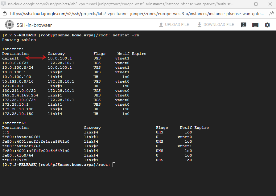
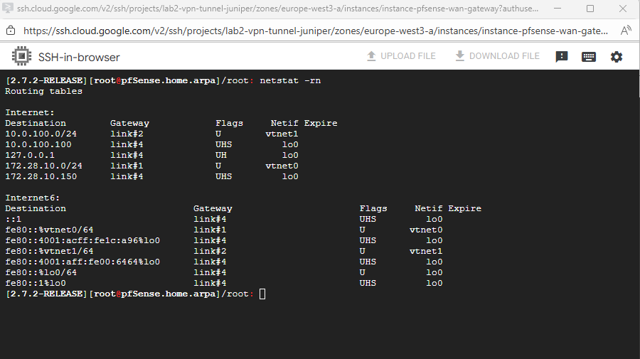
We can check all routes configured on pfSense finally by running the netstat command in pfSense’s shell.
Below we can see already its default gateway set on the WAN interface to access the Internet.
netstat -rn
Configure pfSense to reply to ILB Health Checks
In the following post I was showing in general how we can achieve outbound internet access for GCP VM instances.
I was also showing how to set a custome route in a Spoke VPC subnet to point to a NGFW appliance as next hop running in the Hub VPC.
We cannot directly route traffic from a spoke VPC to the internal IP of an appliance VM in a hub VPC via VPC Network Peering (or by using the Network Connectivity Center (NCC)).
A workaround is to deploy an appliance with two network interfaces, one connected to each VPC, effectively bridging them at the VM level.
This lets you route traffic between VPCs without using an ILB as shown below, simple and functional for lab or demo environments.
But in production, it’s far from ideal since both networks now share a single instance boundary, eliminating the isolation and control that separate VPCs normally provide.
To overcome this we can use an Internal Passthrough Network Load Balancer (ILB).
The Internal Passthrough Network Load Balancer (ILB) acting as a next hop is the standard and correct way to overcome this limitation and enable a centralized firewall appliance architecture in a hub and spoke topology.
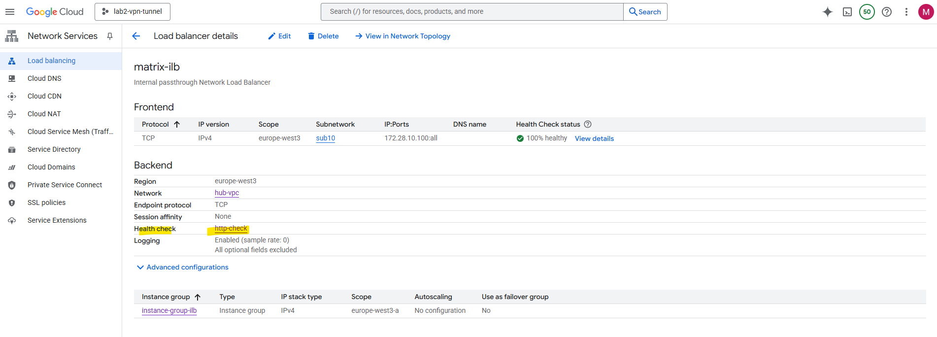
The internal passthrough ILB in GCP delivers packets to its backend pool (in my the pfSense appliance and its internal LAN interface and IP address) but still using the ILB frontend IP (VIP) as the destination.
pfSense initially drops or ignores this traffic because it doesn’t own that IP (ILB frontend IP).
When you create an Internal Passthrough ILB, Google doesn’t use traditional L2 switching or ARP to deliver traffic. Instead, everything, including ILB forwarding and health checks happens inside Google’s Andromeda SDN fabric, which operates at L3 (routing) level with programmable encapsulation and metadata tags.
More about Google’s software-defined networking (SDN) called Andromeda you will find here https://cloud.google.com/vpc/docs/private-service-connect-architecture.
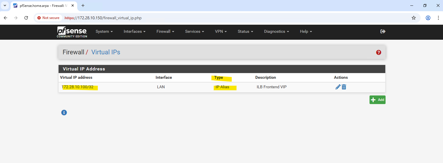
Adding the ILB VIP as an IP Alias on the LAN interface (via Interfaces → Virtual IPs) makes pfSense respond to those packets, allowing the ILB health checks to succeed.
In my case the ILB frontend IP is 172.28.10.100. In pfSense we can add the ILB frontend IP as Virtual IP under Firewall -> Virtual IPs. For the type select IP Alias.
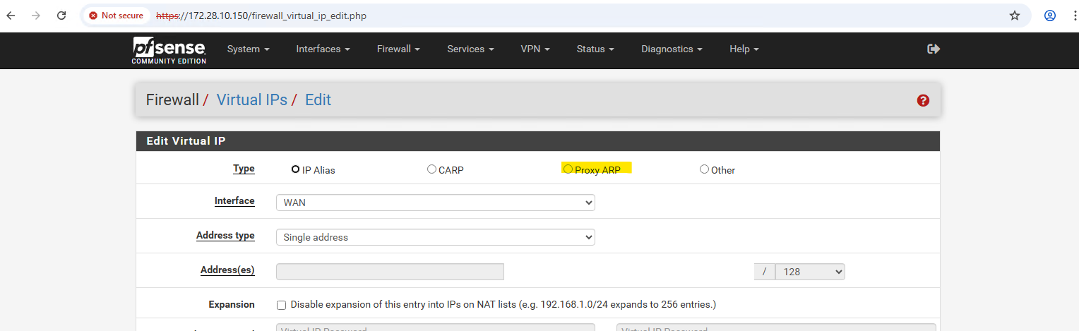
We can select here between different types like also Proxy ARP.
In pfSense, an IP Alias adds an additional IP address that the firewall truly owns and responds to for ARP, ICMP, and TCP/UDP traffic.
A Proxy ARP entry, on the other hand, only makes pfSense answer ARP requests for that IP but does not actually bind or respond to packets destined to it.
Therefore, an IP Alias is required when pfSense itself must handle the traffic, as in the case of a GCP Internal Passthrough Load Balancer.
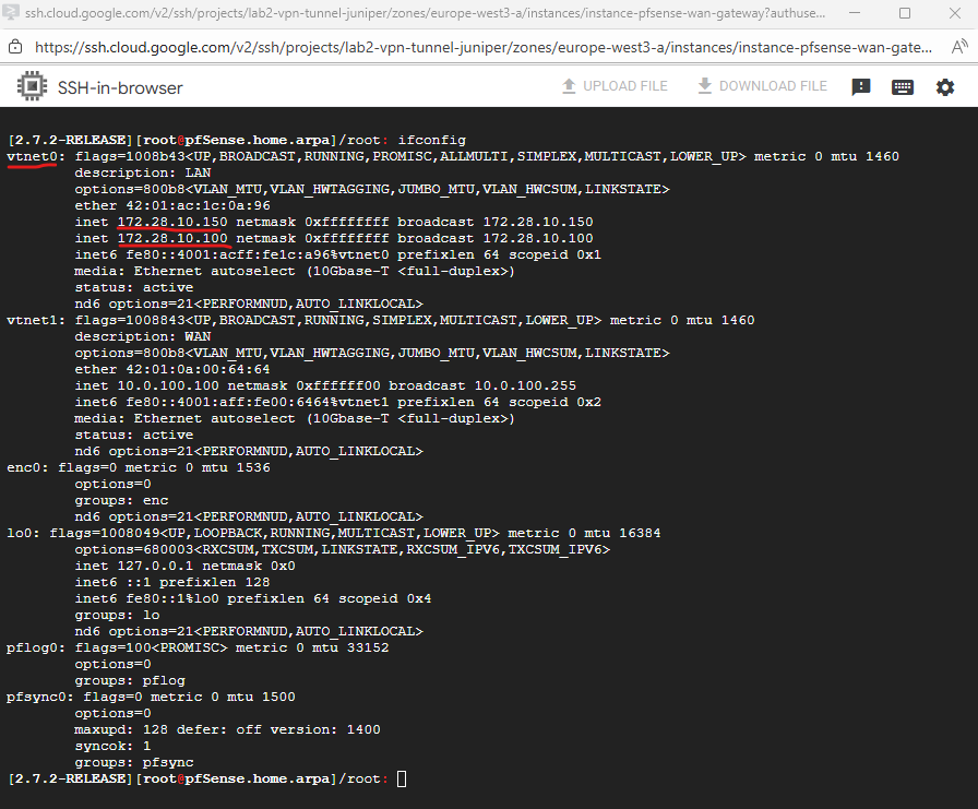
Below when running ifconfig we can see that our IP Alias (ILB frontend IP) with the IP 172.28.10.100 was added as additional IP address to the LAN interface.
In a Google Cloud Internal Passthrough Load Balancer (ILB), health checks are not terminated or proxied by the ILB itself. Instead, Google’s regional health checker systems (with IP ranges 35.191.0.0/16 and 130.211.0.0/22 for west-europe) send probe packets directly to the backend VM.
The key detail is that these probes keep the destination IP address equal to the ILB’s frontend IP (VIP), not the backend’s actual interface IP (in my case pfSense LAN 172.28.10.150 actually) as already mentioned.
So when a health check (or any ILB-bound packet) arrives in the VPC:
- The packet’s destination IP is the ILB’s frontend IP (e.g., 172.28.10.100),
- The Google edge fabric intercepts that traffic at the virtual network layer (before any VM),
- Andromeda then rewrites the next-hop and delivers the packet directly to one of the backend instances’ NICs, but crucially, without changing the original destination IP (still 172.28.10.100).
- From the VM’s point of view, it just received a packet destined to an IP it doesn’t own, unless it’s configured with an alias (as we did on pfSense).
So in pfSense (or any backend VM), the packet trace or firewall log will show entries like below.
Because the ILB operates in passthrough mode, the packet is routed directly to one of the backend instances in the same subnet, preserving both source and destination IPs.
That’s why the backend VM (pfSense) must explicitly own or handle the ILB frontend IP, otherwise, it will receive but never respond to those packets, causing the health check to fail.
So far the packets also will be dropped because not allowed by a firewall rule.
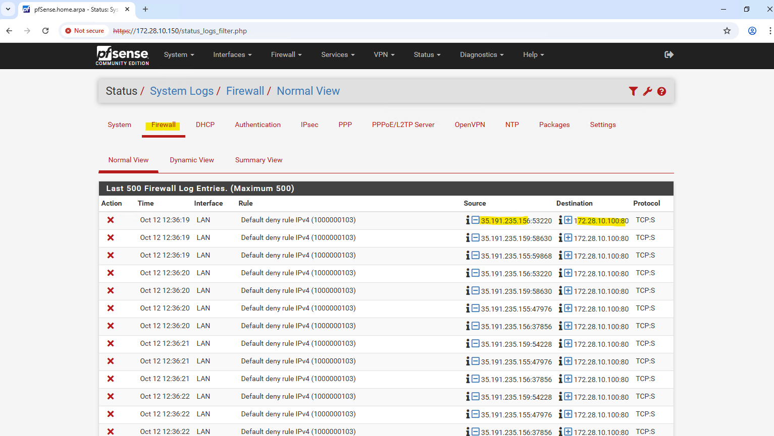
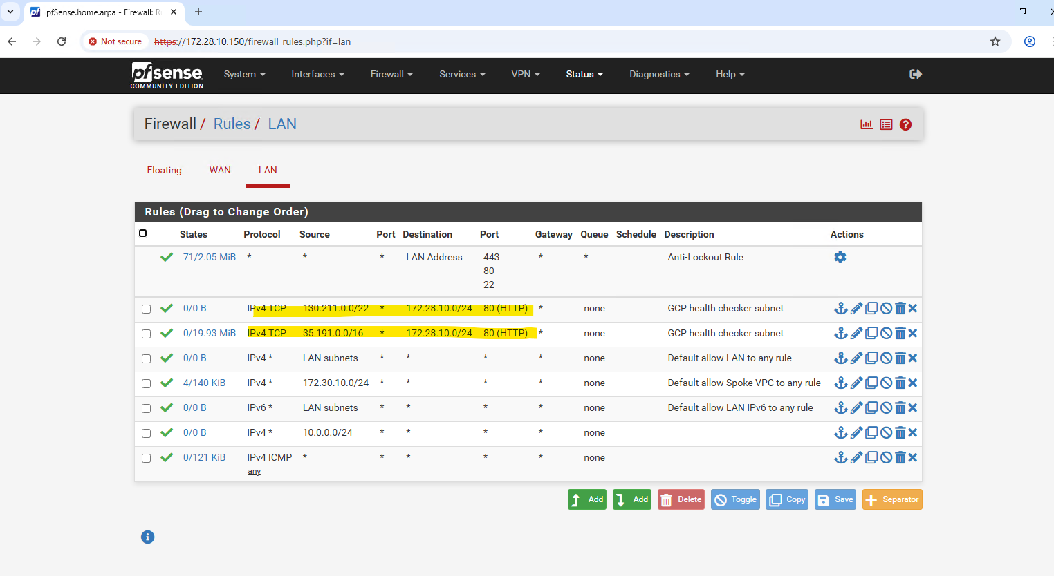
So we also need to allow the IP address range of the ILB Health Checker inbound TCP 80 traffic.
Further we need to make sure, that pfSense can route reply traffic successfully to Google’s regional health checker systems. Therefore we need to add static routes in pfSense using the LAN gateway to reach these systems.
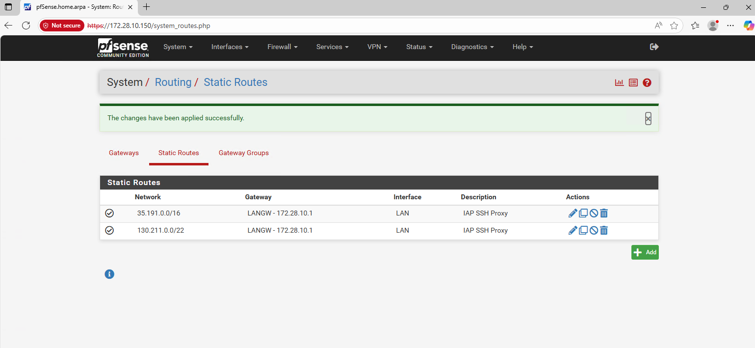
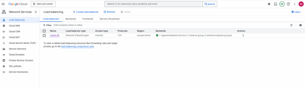
After adding the ILB VIP as an IP Alias, allowing traffic from Google’s regional health checker systems and allowing inbound traffic on pfSense for, the health check in GCP should be finally successful.
For the health check I will use http.
Although pfSense’s WebGUI is configured to use HTTPS by default, it also keeps an HTTP listener active on port 80 for compatibility.
This allows GCP’s Internal Load Balancer health checks to successfully connect using a simple HTTP (TCP/80) probe, even when the main web interface is secured via HTTPS.
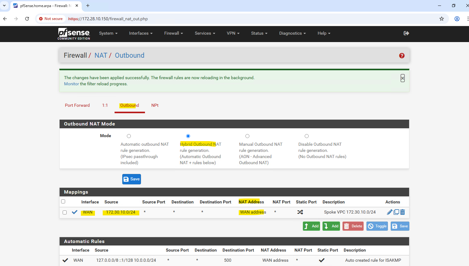
Configuring Outbound NAT for VPC Workloads
The default option is Automatic Outbound NAT which automatically performs NAT from internal interfaces, such as LAN, to external interfaces, such as WAN.
Switching to Hybrid Outbound NAT lets you extend NAT to these additional networks while keeping the defaults for directly connected interfaces.
So below to enable successful outbound internet connections from my Spoke VPC (172.30.10.0/24), I need to add the mapping manually as highlighted. For the Interface select the WAN interface, for the source select the Spoke VPC address range, for the NAT address select WAN address and for the destination select Any (to allow all outbound internet access). Leave the port empty to allow all.
In Google Cloud, outbound (egress) traffic is allowed by default at the VPC firewall level.
Therefore, pfSense’s WAN interface in the untrusted Hub VPC doesn’t need an explicit “allow egress” rule, it can freely initiate Internet connections and forward NATed traffic from the spoke networks.
To block outbound access, we can create an explicit egress deny rule with priority 0 and destination 0.0.0.0/0.
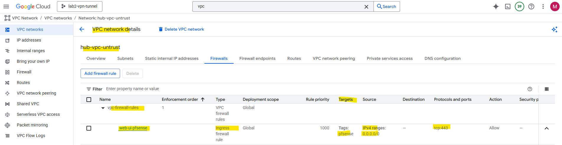
Allow Web UI Access from the Internet
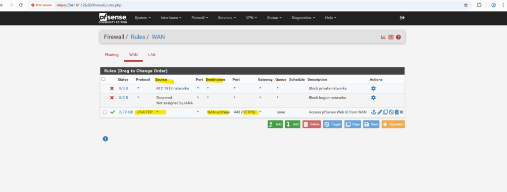
To make the pfSense WebGUI accessible from the Internet via the external IP assigned to the WAN NIC in the untrusted VPC subnet, we must allow ingress TCP 443 on that subnet in GCP and permit HTTPS traffic on pfSense’s WAN interface to its WAN address.
This configuration enables remote administrative access directly over the Internet.
However, exposing the WebGUI publicly is highly insecure and strongly discouraged, it’s far safer to access it through a VPN, bastion host, or private management network.
Allowing ingress (inbound) HTTP TCP 443 traffic on the unstrusted Hub VPC.
For the target we can filter the scope by just applying to specific intstances using a specific network tag.
Allowing inbound HTTPS TCP 443 traffic on pfSense’s WAN interface and its WAN address.
Troubleshooting
Adding Routes temporary
Show all routes in FreeBSD.
root: netstat -rn
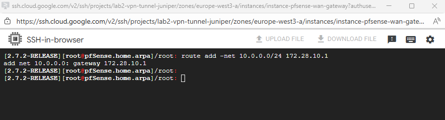
Adding routes in the shell but just temporary.
route add -net <network> <gateway>
route add -net 10.0.0.0/24 172.28.10.1
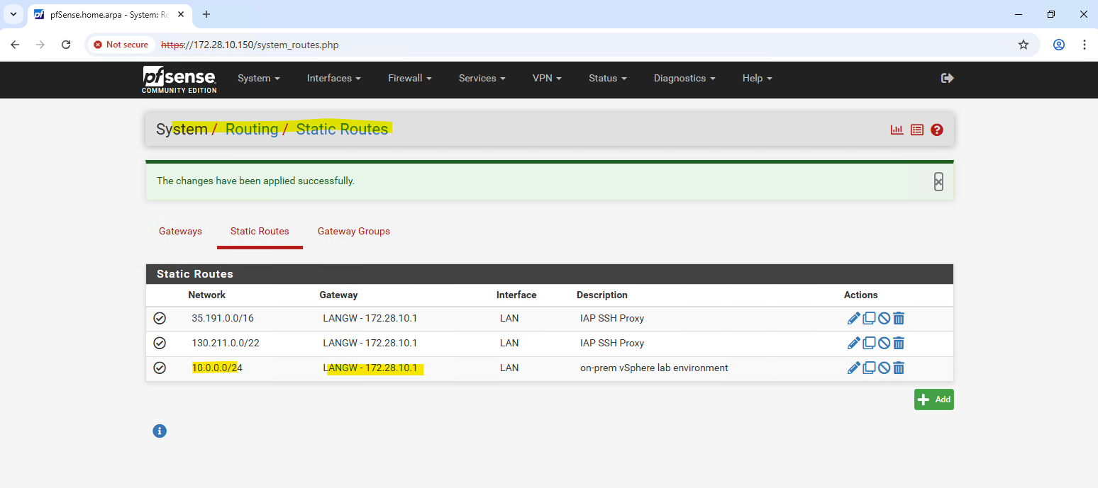
We can set the routes persistently by using the Web UI within System -> Routing -> Static Routes.
Disabling the pfSense Firewall completely and temporary
root: pfctl -d
Adjust Default Gateway by using the pfSense Shell (Interfaces configured for DHCP)
When both interfaces (WAN + LAN) are configured for DHCP, and pfSense will set the default gateway on the LAN interface, the pfSense VM instance in GCP will have no internet access because the external public IP address is assigned to the WAN interface.
Below we will see how to fix this.
In case we have running the pfSense VM instance in GCP like shown here, also have no other VM instances running in the same VPCs network (subnets) as pfSense, also haven’t configured a site-to-site VPN tunnel, we finally won’t have any option to access pfSense’s web gui through its internal private IP addresses (configured on the LAN or WAN interface).
The WAN interface finally is also just a private IP address, but its private gateway IP address, here 172.16.10.1, is able to connect to the internet by using the assigend external IP address on the WAN interface in the Google Cloud console.
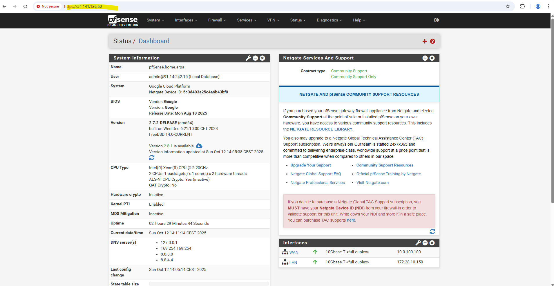
So the only option is to access pfSense’s web gui through the external public IP address.
!! Note !!
Exposing the WebGUI publicly is highly insecure and strongly discouraged, it’s far safer to access it through a VPN, bastion host, or private management network.I will show this nevertheless and just for lab environments and testing, I guess we can take that risk.
To change the default gateway (default route), we must first remove the existing default route and then adding a new one on the WAN interface.
By using just the pfSense shell we first need to enter the shell by pressing (8) on the console.
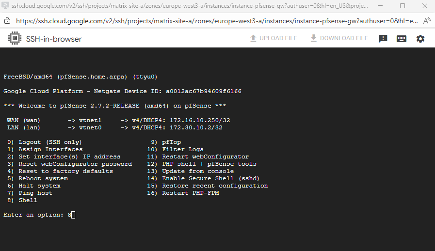
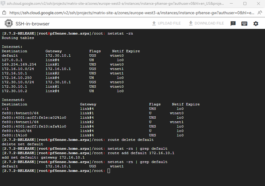
In my case the LAN interface is vtnet0 with the IP address 172.30.10.2 and the WAN interface is vtnet1 with the IP address 172.16.10.250. So the default route finally should be using the WAN interface and IP address 172.16.10.1.
Then we can first temporarily change the default route by running.
# check the current default route
netstat -rn

# delete the default route
route delete default

# check if the default route is deleted successful
netstat -rn | grep default

# add the new default route on the WAN interface
route add default 172.16.10.1
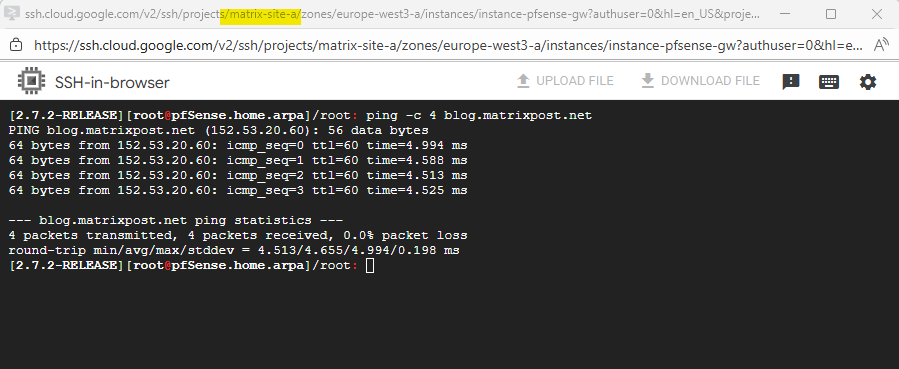
A quick check if outbound internet is working, looks good.
Because so far we weren’t able to configure an inbound allow rule on the WAN interface and TCP port 443 to access the web gui, we temporary need to disable the pfSense firewall in general by running.
# check the current state
pfctl -s info | grep Status

# disable the firewall
pfctl -d

To re-enable it run
pfctl -e
Now we can try to access the web gui directly on the external public IP address we assigned to the WAN interface.
We also first need to allow inbound TCP port 443 traffic on the VPC to which pfSense’s WAN interface is assigned to.
We also first need to disable the web gui refferer check.
When accessing pfSense through the WAN interface, the WebGUI referrer check often blocks the request because the browser’s referrer header doesn’t match pfSense’s expected internal (LAN) address or hostname.
This is a built-in CSRF protection mechanism designed to prevent forged administrative requests from untrusted networks. In cloud environments like GCP, the additional NAT layer makes WAN access appear external, which commonly triggers this security check.
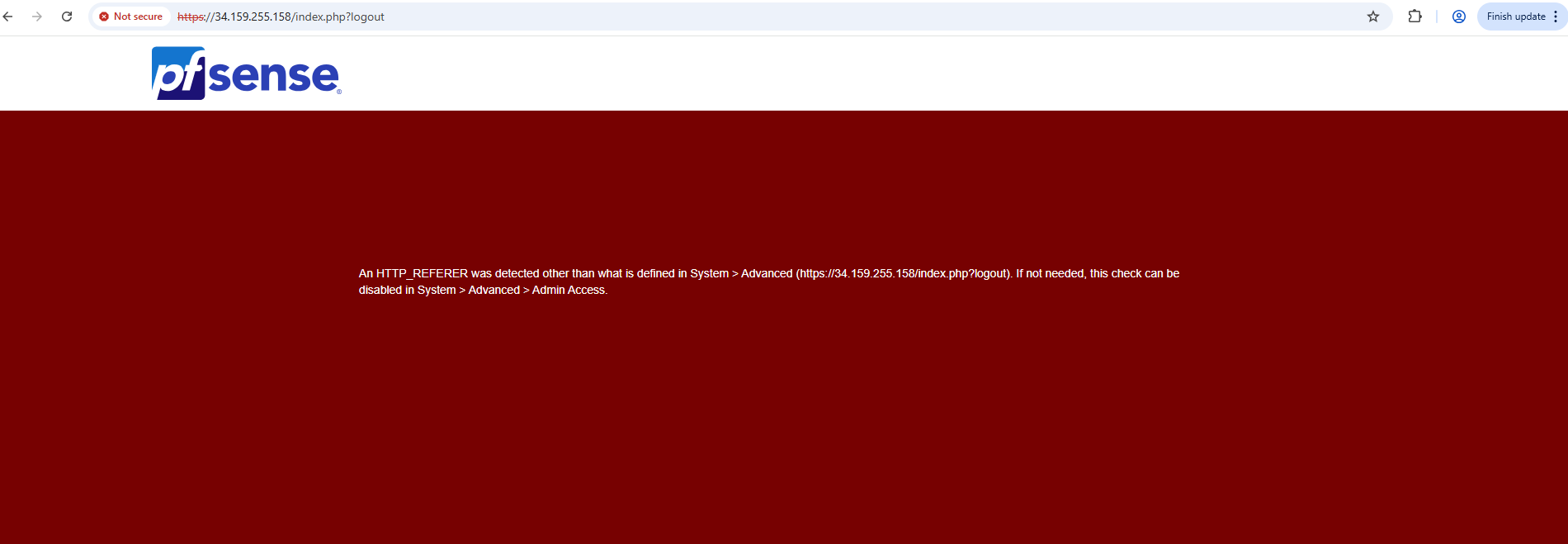
To disable the the web gui refferer check, run.
pfSsh.php playback disablereferercheck
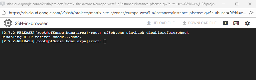
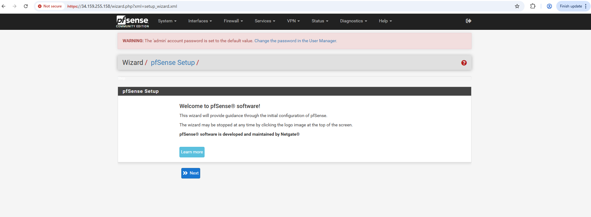
We are now able to finally access pfSense through the external public IP address for the initial configuration.
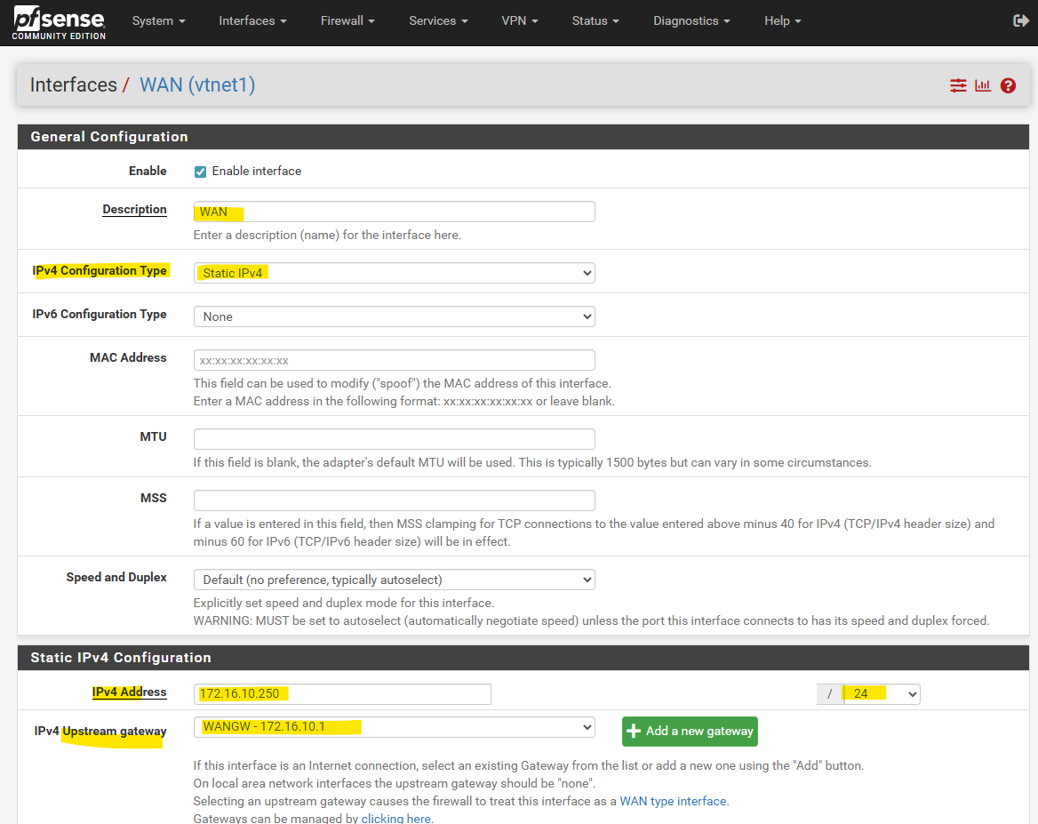
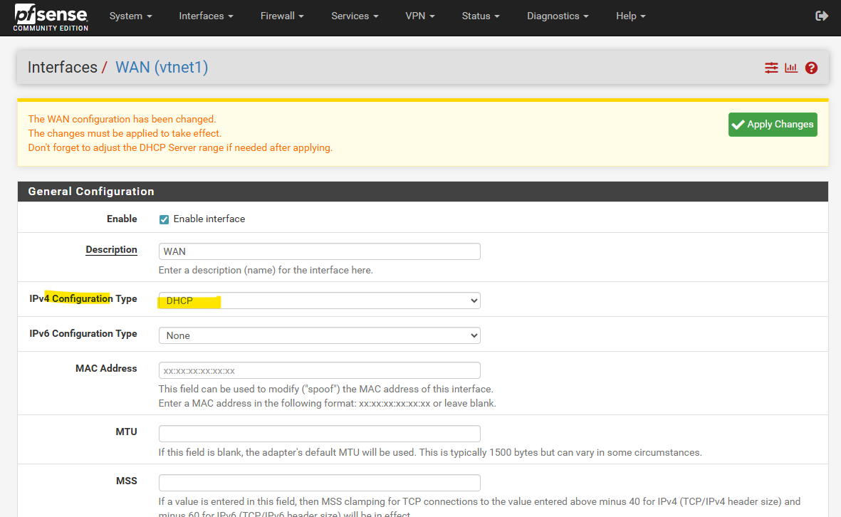
To make the default gateway (default route) persistent, we first need to assign the IP address of the WAN interface by using the static IPv4 configuration.
So far the default gateway in the pfSense web gui is still set automatically on our LAN interface (per DHCP).
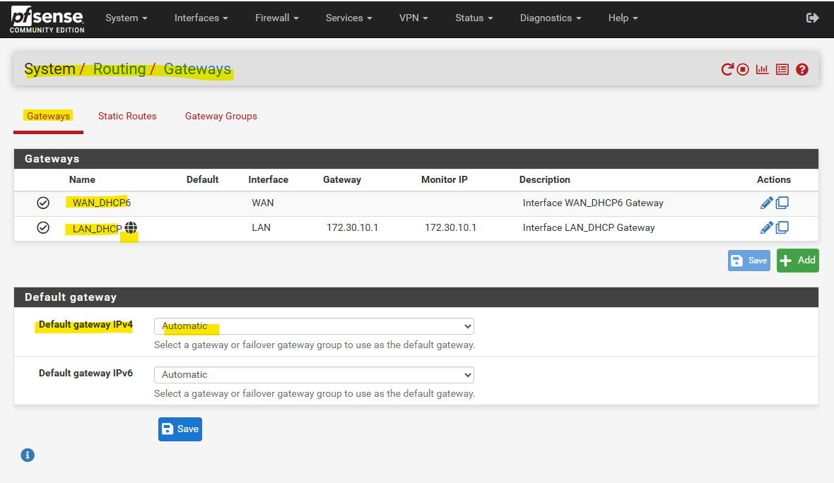
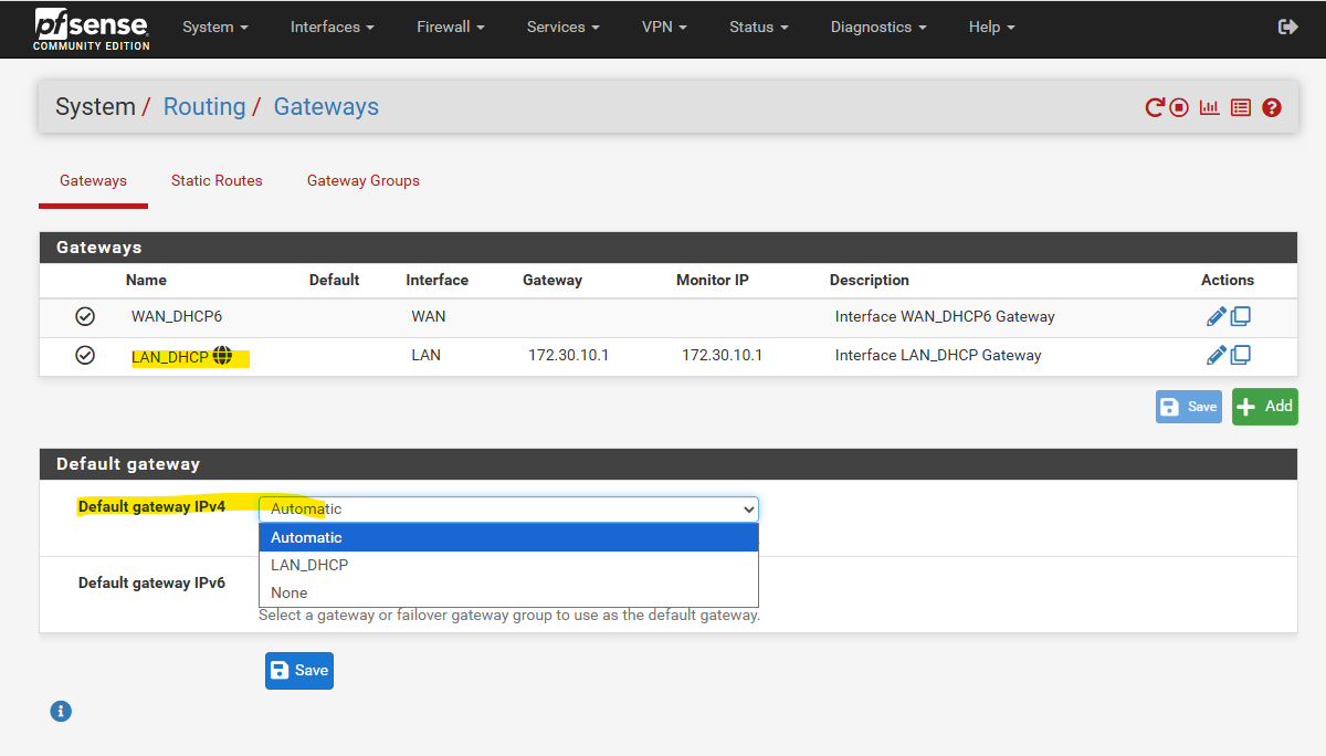
So far we cannot select the WAN gateway.
So first we switch to static IPv4 to enter the WAN IP address (172.16.10.250) and further we also need to add the IPv4 upsteam gateway (172.16.10.1 – default gateway /default route) manually below when switching to static IPv4.
When you assign an upstream gateway to an interface (like the WAN), pfSense automatically adds a reply-to directive to all firewall rules on that interface by default.
Any packet that enters the interface will have its return traffic forced back out through the same interface’s gateway, regardless of the system’s normal routing table.
It’s pfSense’s way of ensuring asymmetric routing never happens, especially when multiple WANs or gateways exist.
Looks good!
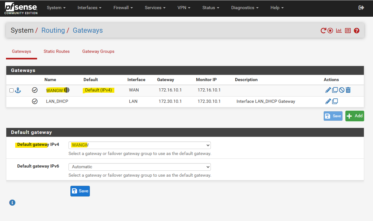
We can now switch back to DHCP on the WAN interface.
The default gateway will be still the WAN interface and its upstream gateway we configured.
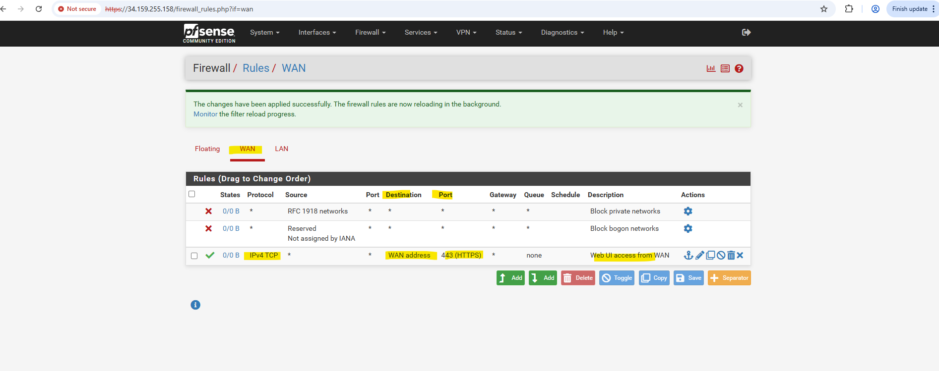
And finally allow inbound TCP port 443 traffic on the WAN interface and address to access the web gui through the extenal public IP address.
!! Again !!
Exposing the WebGUI publicly is highly insecure and strongly discouraged, it’s far safer to access it through a VPN, bastion host, or private management network.Just do this temporary and just for lab environments and testing.
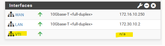
Issues with VTI interfaces running in GCP on pfSense version prior 2.8
In pfSense 2.7.2, the configured VTI interface for an IPsec tunnel in GCP remained without an assigned IP address (n/a), even though Phase 2 was connected, preventing BGP from establishing.
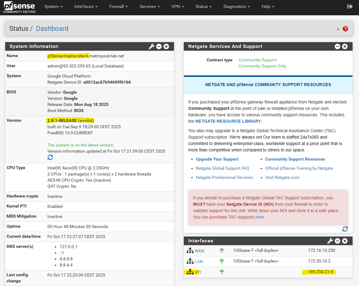
After upgrading to pfSense 2.8.1, the APIPA address was assigned to the VTI interface immediately after configuration without any further changes.
This behavior points to a VTI handling fix introduced in pfSense 2.8, improving reliability of interface creation and automatic IP assignment for route-based IPsec tunnels.
pfSense blocks APIPA traffic by default for security reasons.
To use APIPA-based transit networks successfully on pfSense, we must first enable APIPA traffic in the advanced system settings or by applying a short PHP command to disable the default block rule.
More about in my following post https://blog.matrixpost.net/pfsense-and-apipa-169-254-16-enabling-link-local-transit-networks-for-ipsec-vti-and-bgp/.
More about pfSense you will also find here https://blog.matrixpost.net/?category=pfsense.
Links
Installing pfSense on Google Cloud Platform
https://blog.kylemanna.com/cloud/pfsense-on-google-cloud/pfSense with multiple interfaces in GCP
https://www.youtube.com/watch?v=cMCqZ4nd6lspfSense – Outbound NAT
https://docs.netgate.com/pfsense/en/latest/nat/outbound.htmlSoftware-Defined Networking (SDN) – Google Cloud called Andromeda
https://cloud.google.com/vpc/docs/private-service-connect-architectureSecure Google Cloud Hub-and-Spoke with VM-Series (Architecture to secure north/south and east/west traffic for spoke VPC networks)
https://github.com/PaloAltoNetworks/google-cloud-hub-spoke-tutorial