How to deploy a vSphere Distributed Switch in vCenter
In this post I want to show step by step how we can deploy a vSphere Distributed Switch in vCenter.
In vSphere you can choose between standard vSwitches and distributed vSwitches. Without vCenter you are just able to configure and maintain standard vSwitches individually on each ESXi Host by hand. The distributed vSwitches is a feature provided by the vCenter Server system which simplifies deploying and scalability for virtual switches on ESXi Hosts.
A vSphere Distributed Switch provides centralized management and monitoring of the networking configuration of all hosts that are associated with the switch. You set up a distributed switch on a vCenter Server system, and its settings are propagated to all hosts that are associated with the switch
Introduction
A network switch in vSphere consists of two logical sections that are the data plane and the management plane. The data plane implements the packet switching, filtering, tagging, and so on. The management plane is the control structure that you use to configure the data plane functionality. A vSphere Standard Switch contains both data and management planes, and you configure and maintain each standard switch individually.
A vSphere Distributed Switch separates the data plane and the management plane. The management functionality of the distributed switch resides on the vCenter Server system that lets you administer the networking configuration of your environment on a data center level. The data plane remains locally on every host that is associated with the distributed switch. The data plane section of the distributed switch is called a host proxy switch. The networking configuration that you create on vCenter Server (the management plane) is automatically pushed down to all host proxy switches (the data plane).
The vSphere Distributed Switch introduces two abstractions that you use to create consistent networking configuration for physical NICs, virtual machines, and VMkernel services.
Distributed Port Groups
Distributed port groups provide network connectivity to virtual machines and accommodate VMkernel traffic. You identify each distributed port group by using a network label, which must be unique to the current data center. You configure NIC teaming, failover, load balancing, VLAN, security, traffic shaping, and other policies on distributed port groups.
The virtual ports that are connected to a distributed port group share the same properties that are configured to the distributed port group. As with uplink port groups, the configuration that you set on distributed port groups on vCenter Server (the management plane) is automatically propagated to all hosts on the distributed switch through their host proxy switches (the data plane). In this way you can configure a group of virtual machines to share the same networking configuration by associating the virtual machines to the same distributed port group.
For example, suppose that you create a vSphere Distributed Switch on your data center and associate two hosts with it. You configure three uplinks to the uplink port group and connect a physical NIC from each host to an uplink. Each uplink has two physical NICs, one from each host which is mapped to it. For example, Uplink 1 is configured with vmnic0 from Host 1 and Host 2. Next you create the Production and the VMkernel network distributed port groups for virtual machine networking and VMkernel services. Respectively, a representation of the Production and the VMkernel network port groups is also created on Host 1 and Host 2. All policies that you set to the Production and the VMkernel network port groups are propagated to their representations on Host 1 and Host 2.
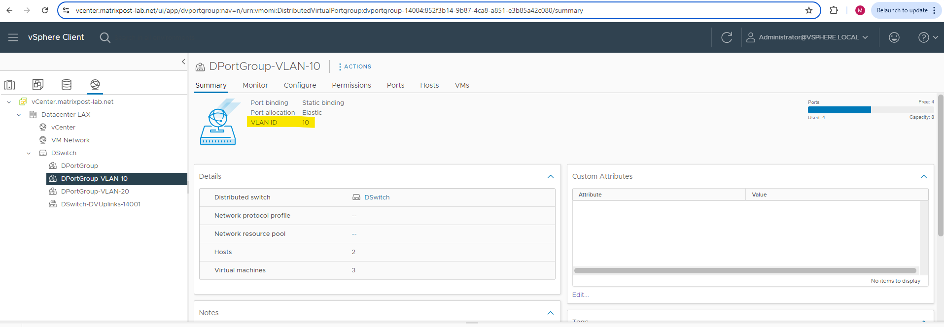
Distributed port group in vCenter.
Uplink Port Groups
An uplink port group or dvuplink port group is defined during the creation of the distributed switch and can have one or more uplinks. An uplink is a template that you use to configure physical connections of hosts as well as failover and load balancing policies.
You map physical NICs of hosts to uplinks on the distributed switch. At the host level, each physical NIC is connected to an uplink port with a particular ID. You set failover and load balancing policies over uplinks and the policies are automatically propagated to the host proxy switches, or the data plane. In this way you can apply consistent failover and load balancing configuration for the physical NICs of all hosts that are associated with the distributed switch.
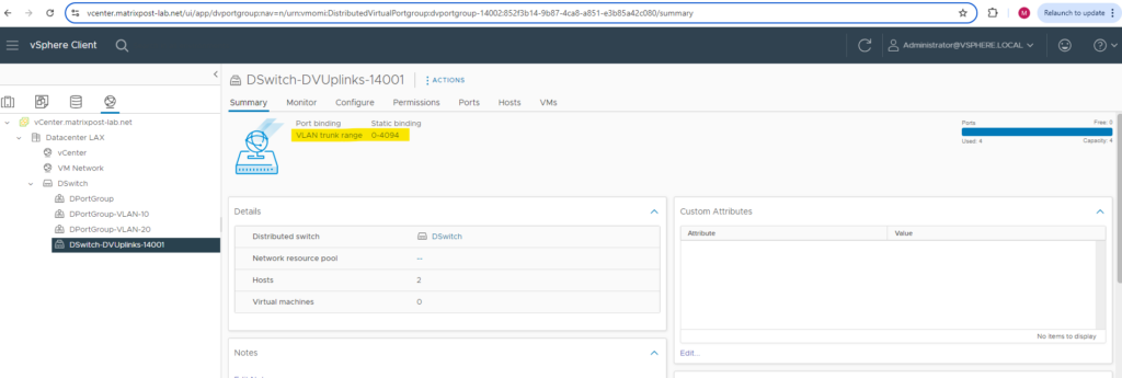
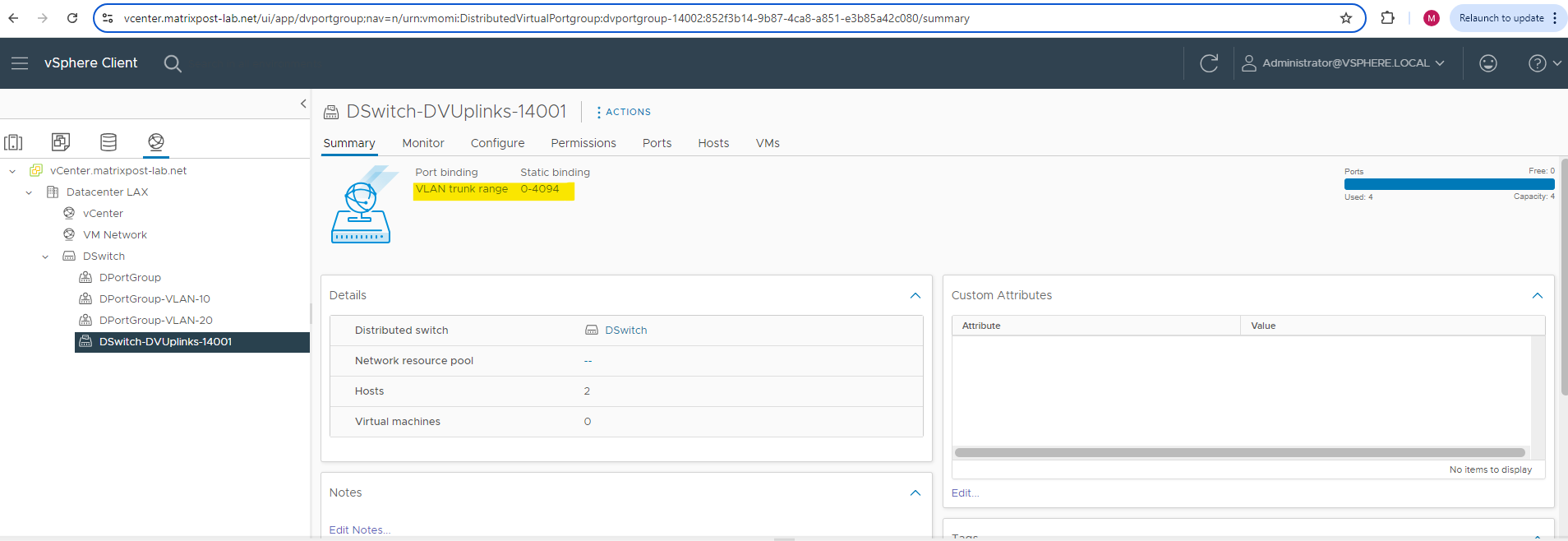
Uplink port group resp. dvuplink port group in vCenter. By default configured as VLAN trunk for the range 0-4094.
Create a new Distributed Switch
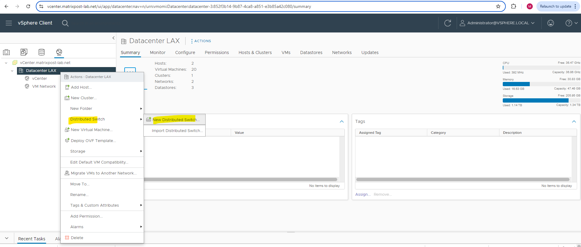
To create a new distributed virtual switch we have to navigate in vCenter to a datacenter node (no matter if under Hosts and Clusters, VMs and Templates, Storage or Networking) and right click on it.
Your ESXi hosts should be in the datacenter, which is a logical organization unit in vCenter.
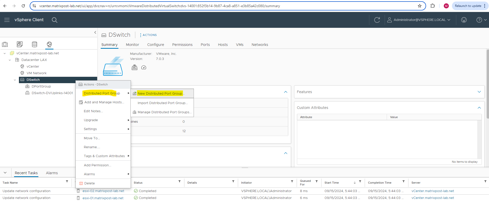
Then select Distributed Switch -> New Distributed Switch.
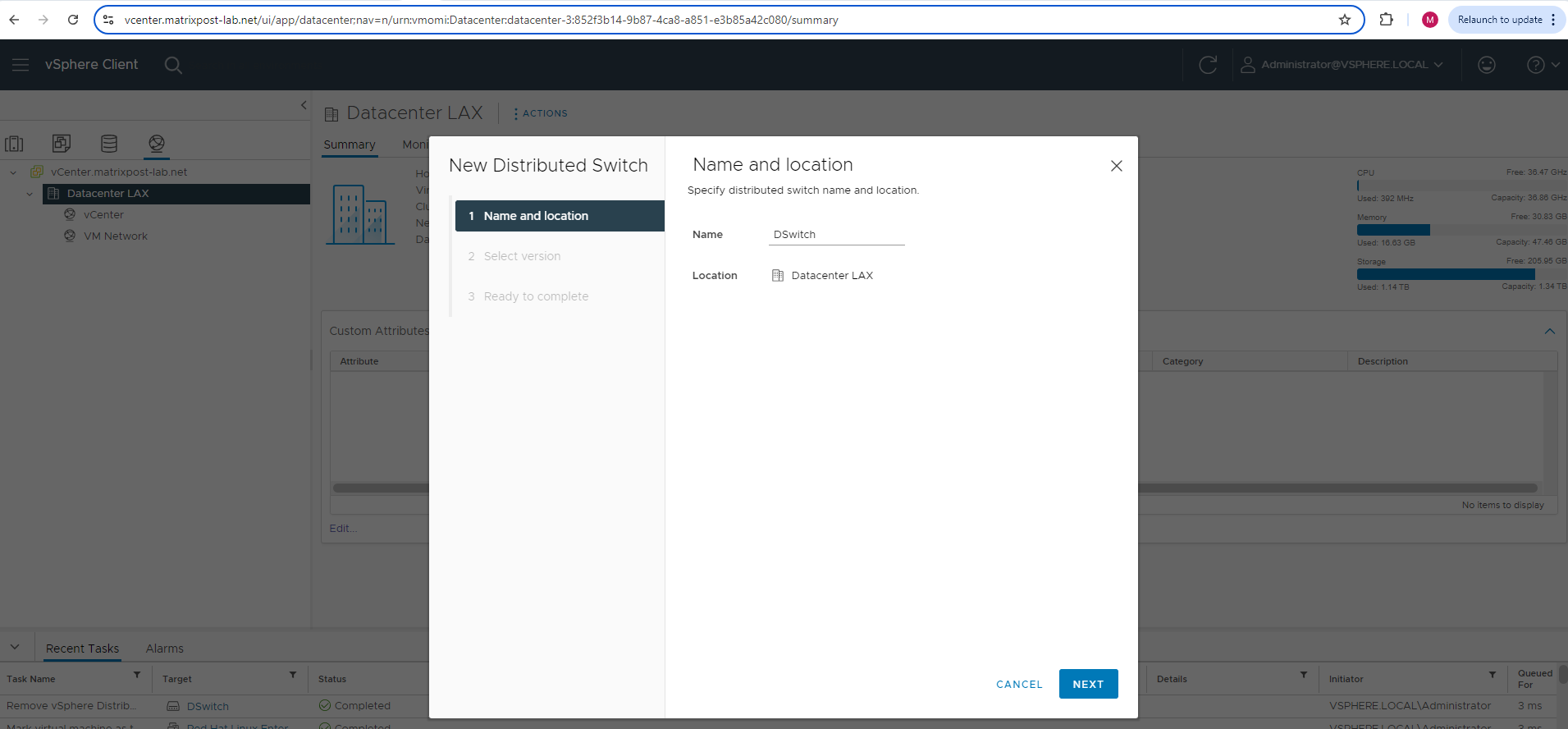
Enter a name for the new distributed virtual switch.
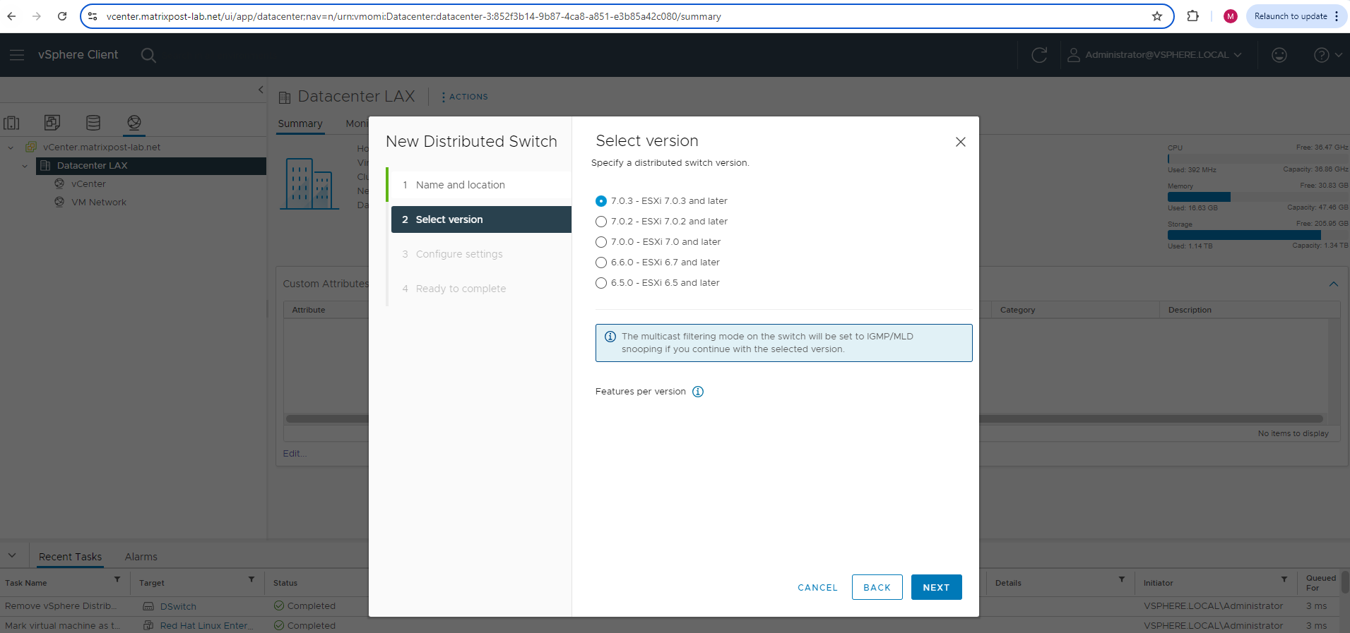
Select a distributed switch version. In my lab environment both ESXi Hosts are running on version 7.0.3, so I can leave the pre-selected version 7.0.3 below.
Finally you should select here a version which will still support your lowest ESXi Host version your are running in your environment.
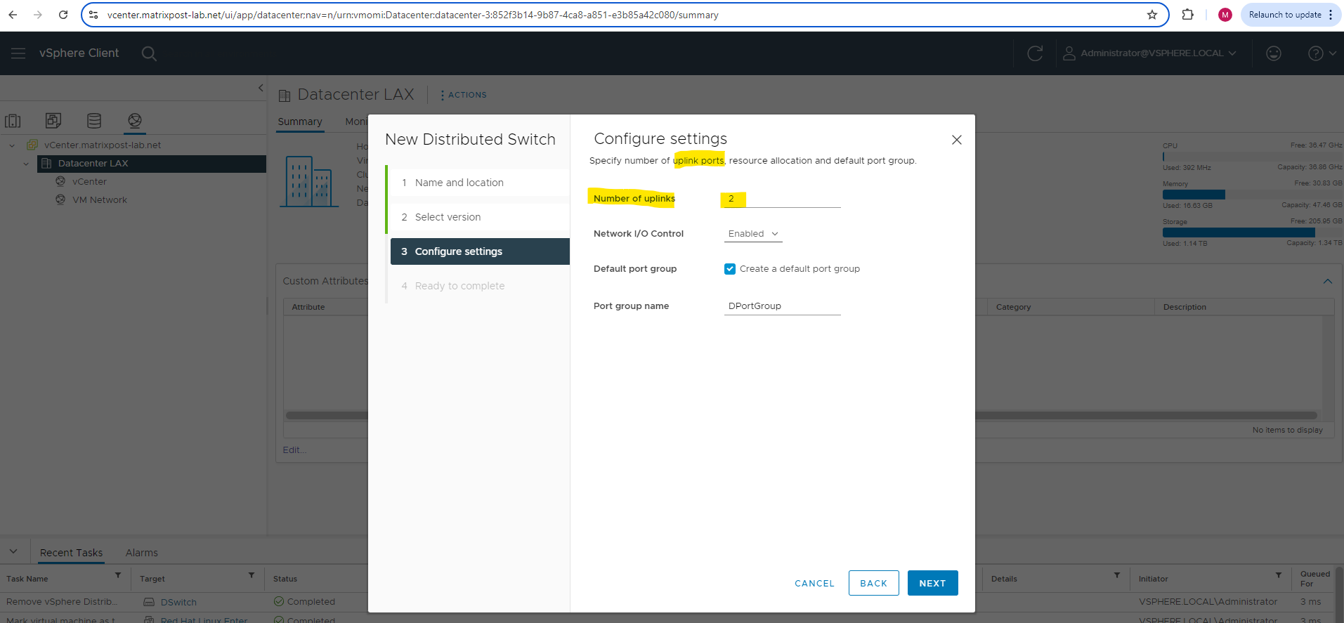
Specify the number of uplink ports below. Best practice is to have at least two uplink ports for the distributed virtual switch and therefore also for the port groups we create later on to provide redundancy in case one NIC will fail.
This will create an uplink port group or dvuplink port group which will consists of at least one uplink. In my case two uplinks will be created below. The number of uplink ports here finally should reflect the number of physical NICs on each ESXi Hosts you want to use for this distributed virtual switch. So each of my ESXi Hosts will have three NICs, one I will use dedicated for the VMKernel network and vMotion and the other two NICs just for virtual machines and therefore this distributed virtual switch.
An uplink is a template that you use to configure physical connections of hosts as well as failover and load balancing policies. You map physical NICs of hosts to uplinks on the distributed switch. At the host level, each physical NIC is connected to an uplink port with a particular ID. You set failover and load balancing policies over uplinks and the policies are automatically propagated to the host proxy switches, or the data plane. In this way you can apply consistent failover and load balancing configuration for the physical NICs of all hosts that are associated with the distributed switch.
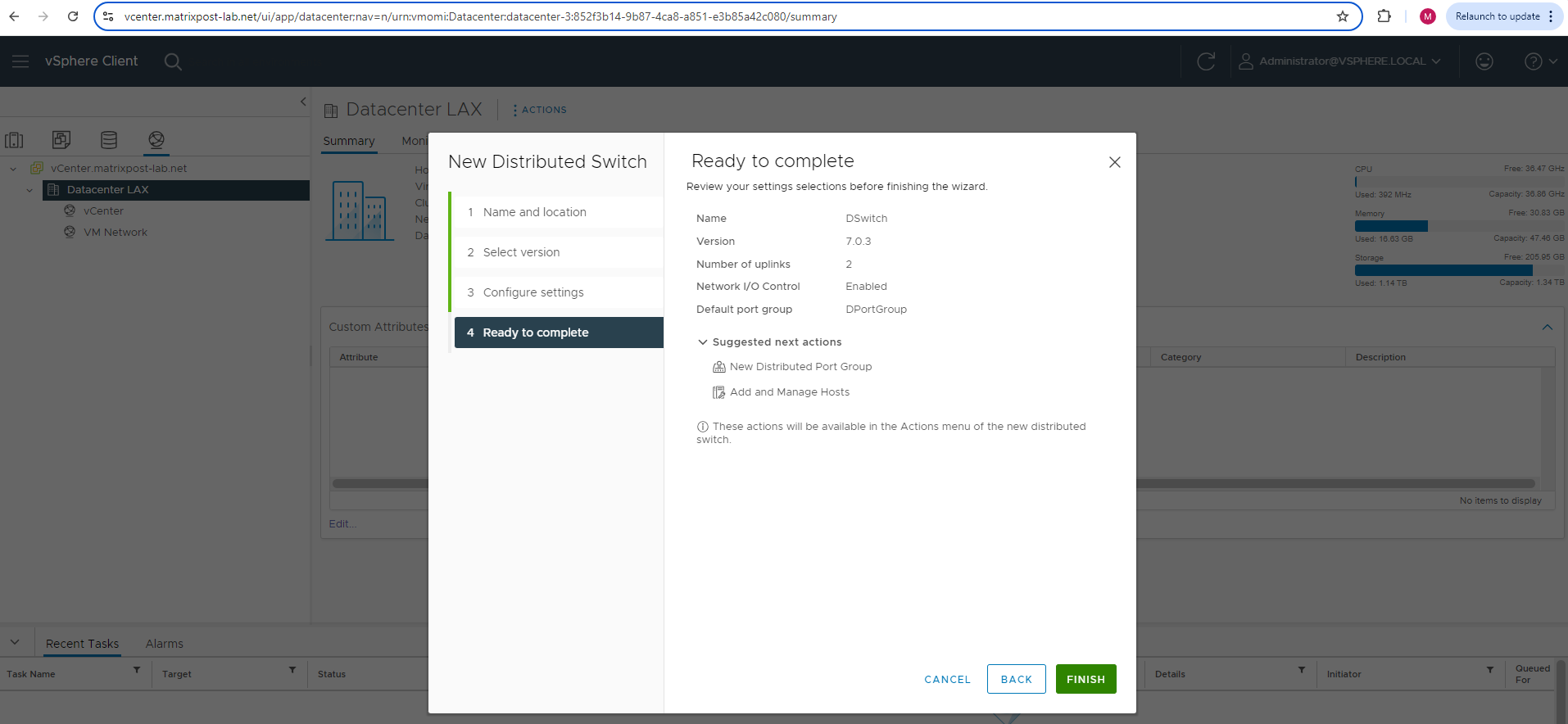
Review the setting and finally click on FINISH.
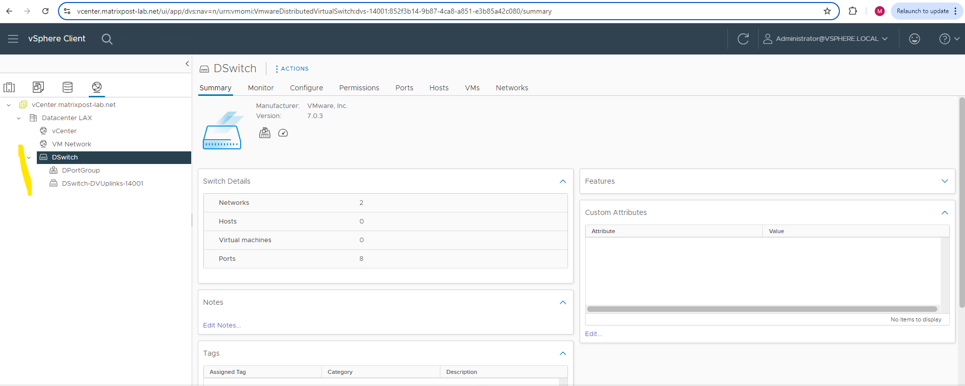
Below you can see that in addition to the distributed virtual switch also as mentioned a default port group and dvuplink port group was created.
The default port group is configured by default without VLAN.
Under Networking -> Datacenter -> <distributed virtual switch> -> Configure -> Properties we can see the settings for our distributed virtual switch.
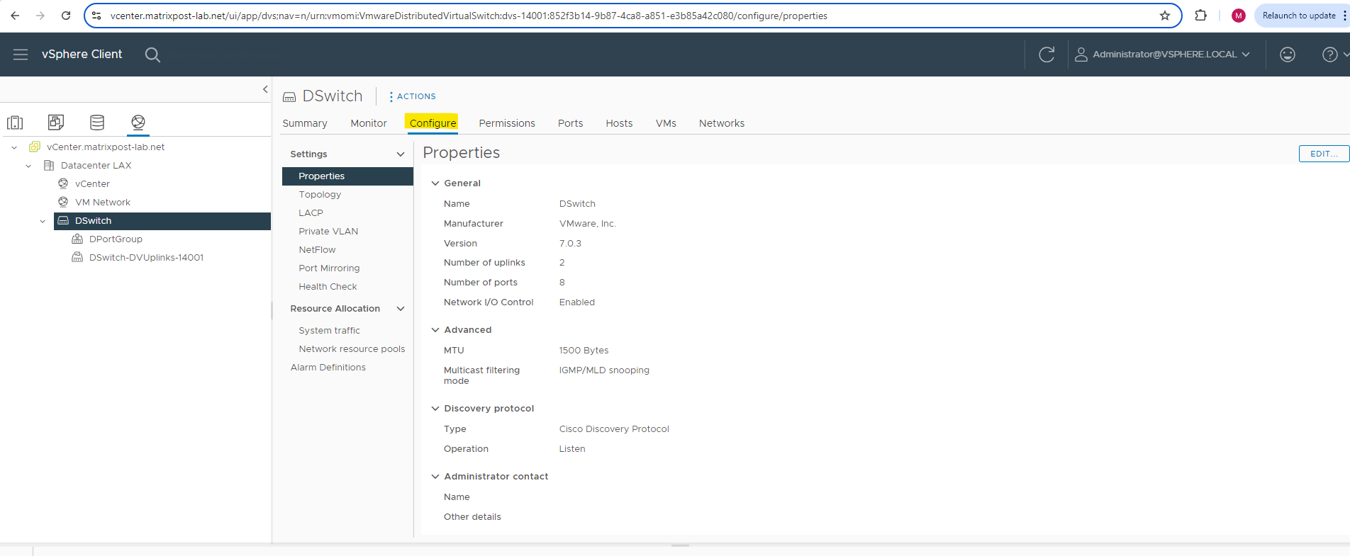
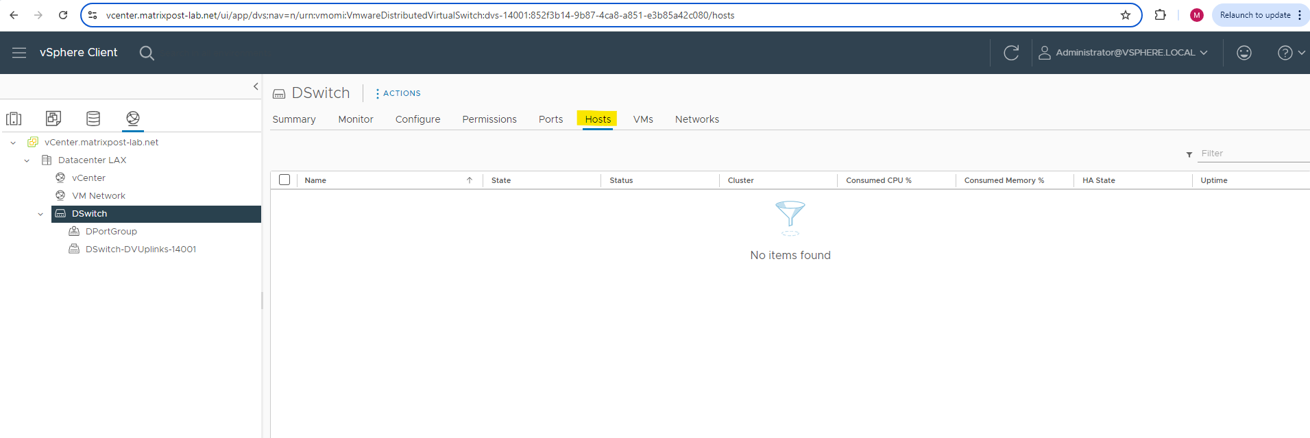
So far our distributed virtual switch is not deployed (associated) to any ESXi hosts in my lab environment and therefore so far also not to any virtual machines.
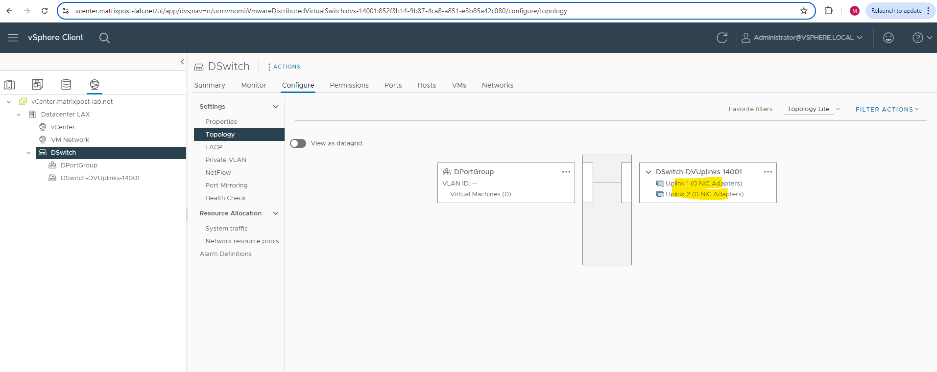
On the Topology section you can see the previously configured uplink ports which later will be associated with the physical NICs of the ESXi Hosts.
As already mentioned, I was configuring two uplink ports. Both of my ESXi Hosts will have three physical NICs, from which I will use two of these physical NICs on each ESXi Host for the distributed virtual switch and connected to these uplink ports. So finally the deployed distributed virtual switch on the ESXi Hosts (so called host proxy switch) will have two physical NICs of the ESXi Host connected to.
Best practice as mentioned is to assign at least two physical NICs to standard virtual switches and distributed virtual switches to provide redundancy in case one NIC will fail.
Network Configuration on the ESXi Hosts before associating them to the distributed vSwitch
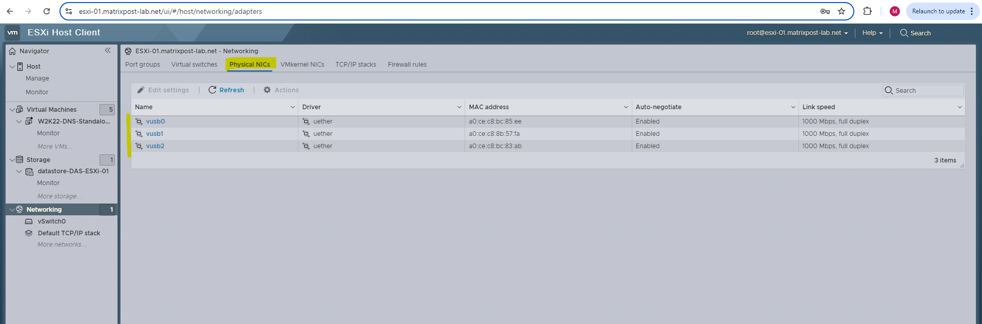
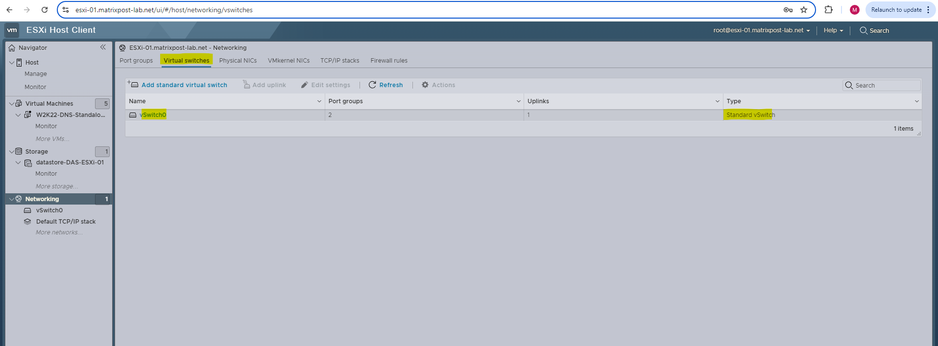
Before deploying and associating this distributed virtual switch to my ESXi Hosts, the networking section on these ESXi Hosts looks like below.
Each ESXi Host will have as mentioned three NICs, in my case below named vusb0 – vusb2 because I will use in my lab environment notebooks with attached USB NICs.
Usually when using normal NICs they will be named vmnic0, vmnic1, vmnic2, … . The VMKernel NIC used for ESXi Hosts network traffic itself, will always be named vmk0, vmk1, … no matter if using USB NICs or classic NICs.
Just one virtual switch named vSwitch0 which is used by the management network and vCenter appliance so far was created on each ESXi Host.
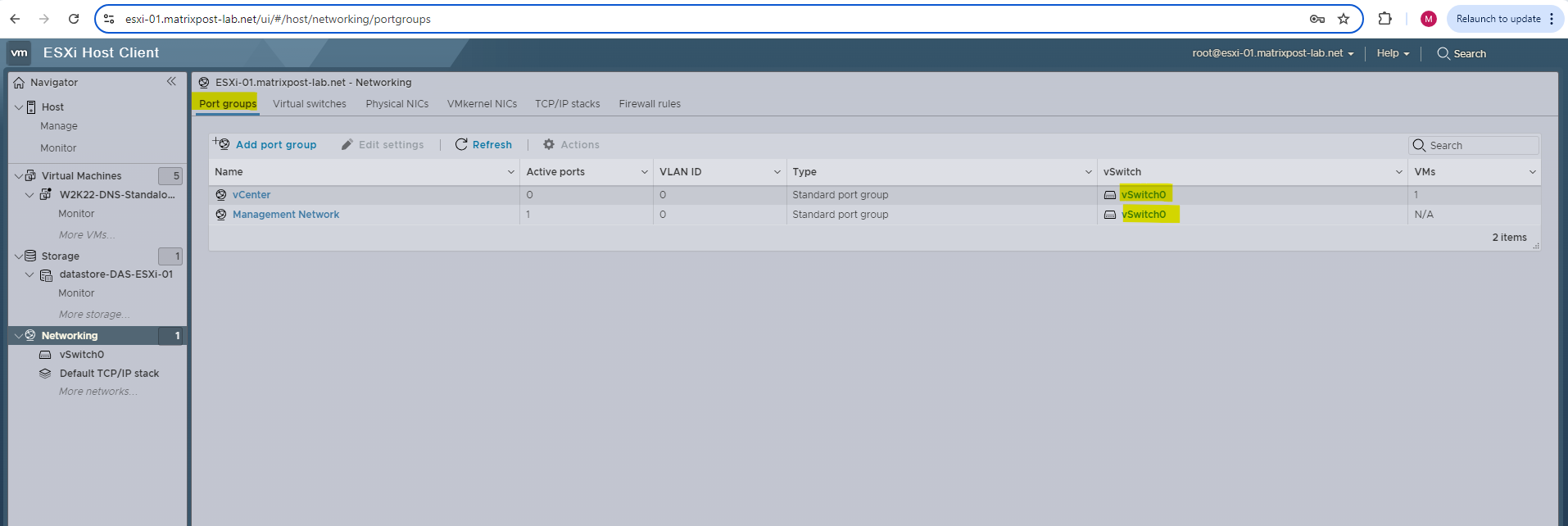
Further two port groups are configured and both using the vSwitch0 (first physical NIC). One is as mentioned for the management network and one for the vCenter appliance.
Next we will see what happens here when we deploy and associate our distributed virtual switch with the ESXi Hosts.
Deploy and associate the Virtual Distributed Switch to the ESXi Hosts
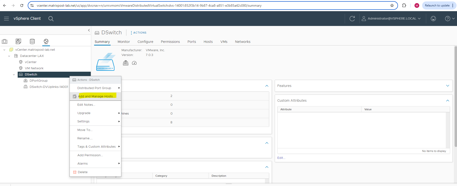
In order to associate our distributed virtual switch with our ESXi Hosts you can right click on the distributed virtual switch and select Add and Manage Hosts … .
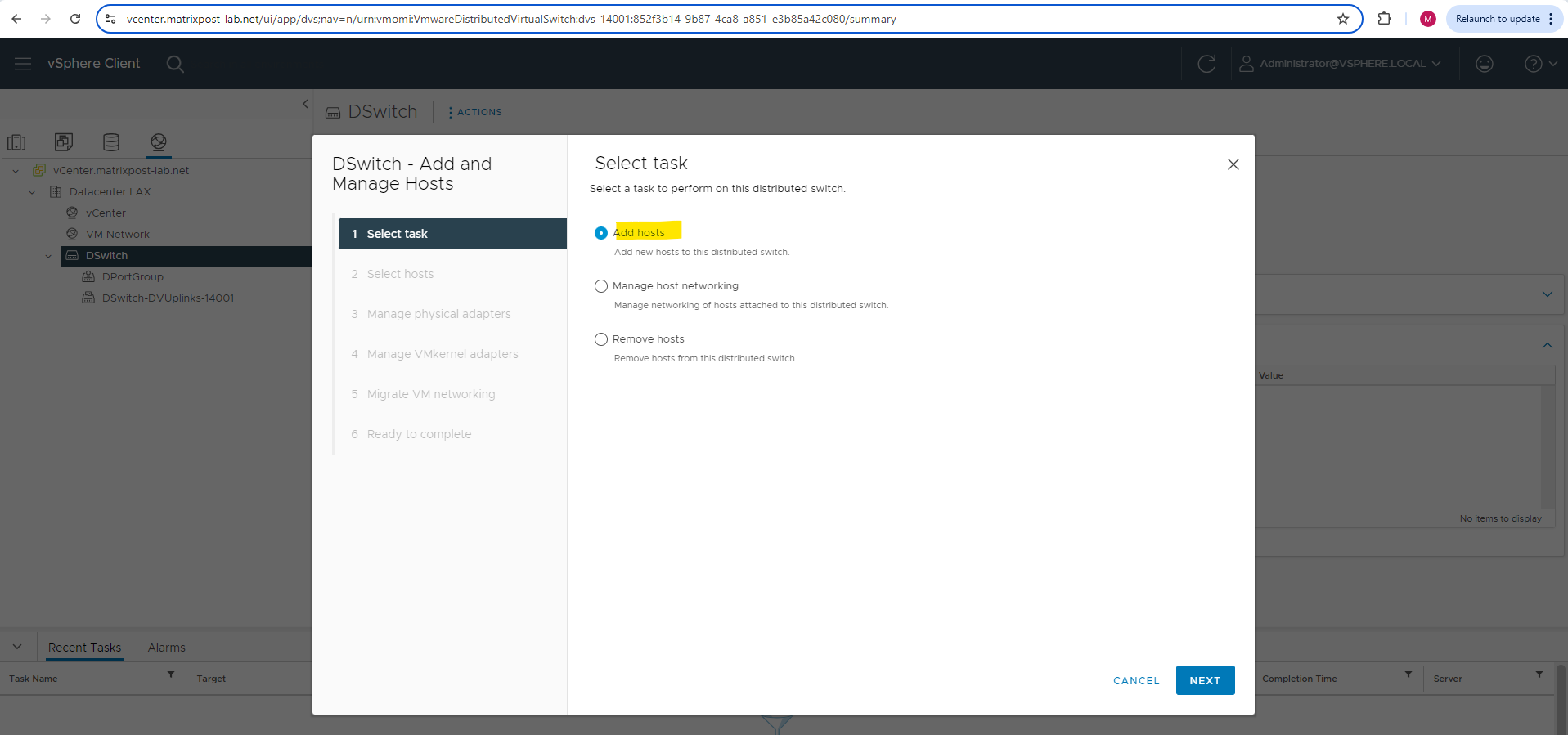
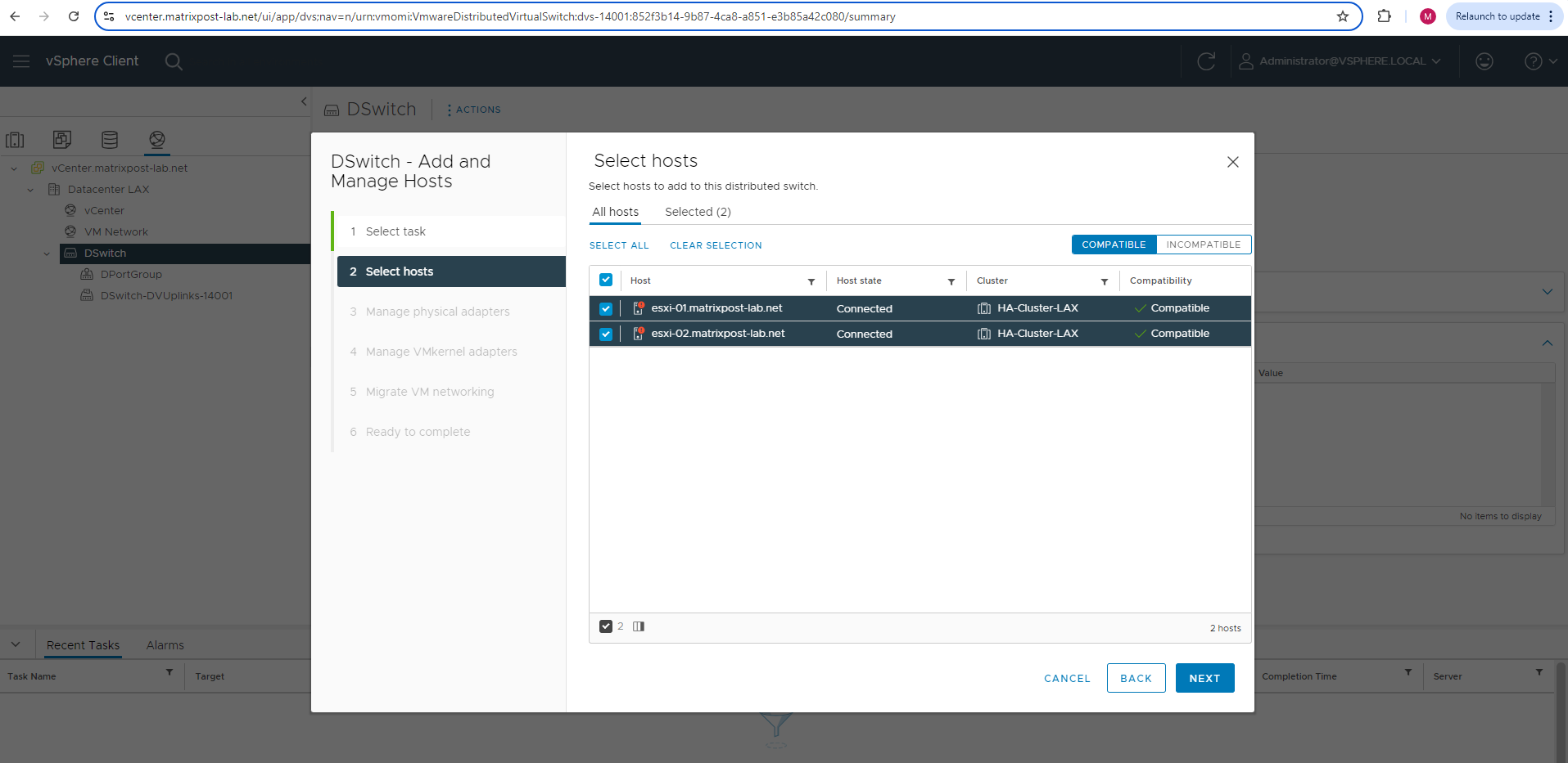
Select Add hosts.
Select the hosts you want to associate with this distributed virtual switch. I will select both of my ESXi Hosts.
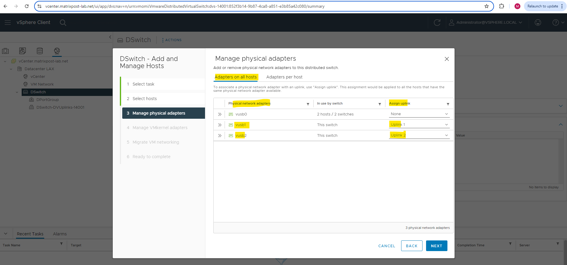
On the Manage physical adapters page we will see all the physical NICs from each previous added ESXi Host. You will see a tab with adapters which are available on all ESXi Hosts and a tab with adapters per host in case they are not the same on each.
In my case both hosts will have the same physical NICs (USB NICs) installed on and therefore I can use the first tab to configure resp. associate them to the distributed virtual switch.
As mentioned, the first NIC is already used for the management network and the vCenter appliance, therefore I will associate my second and third NIC to the distributed virtual switch and its two uplink ports.
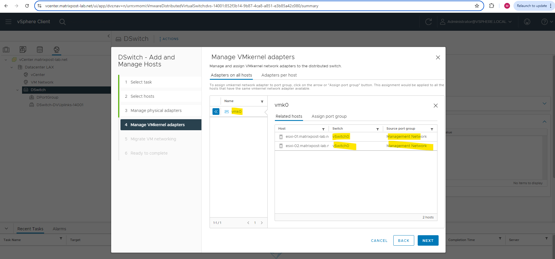
We can also assign vmkernel adpaters to port groups on the distributed virtual switch.
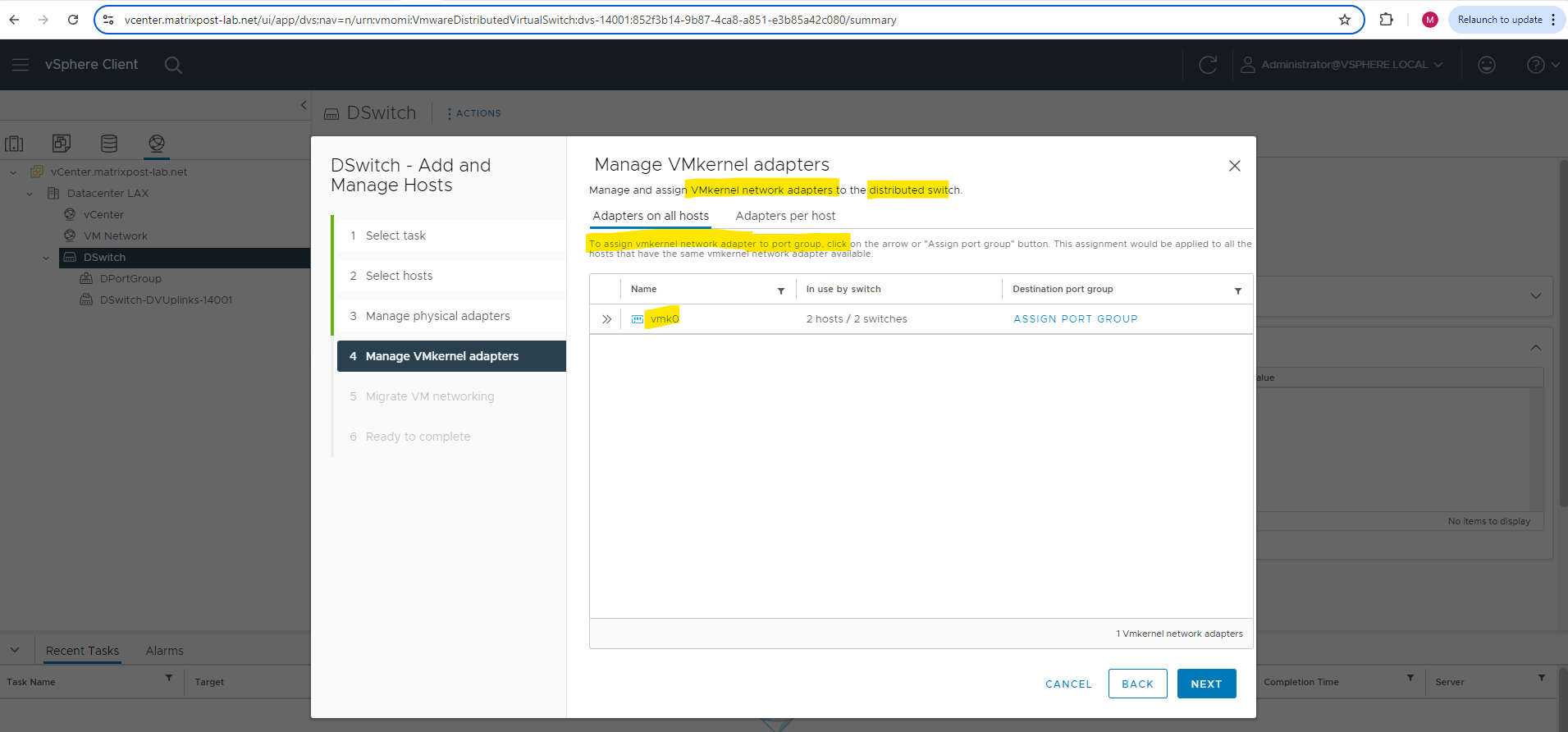
I will left both standard (default) virtual switches associated to the VMKernel adapters and not assign them to the distributed virtual switch.
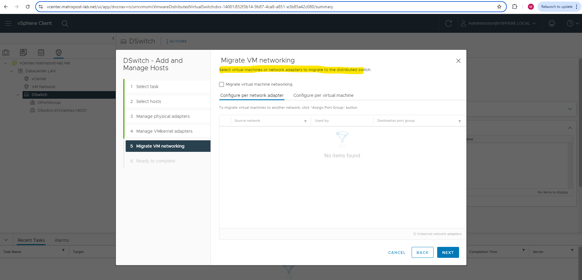
If you need to migrate virtual machines or other network adapters to the distributed virtual switch, you can configure this below.
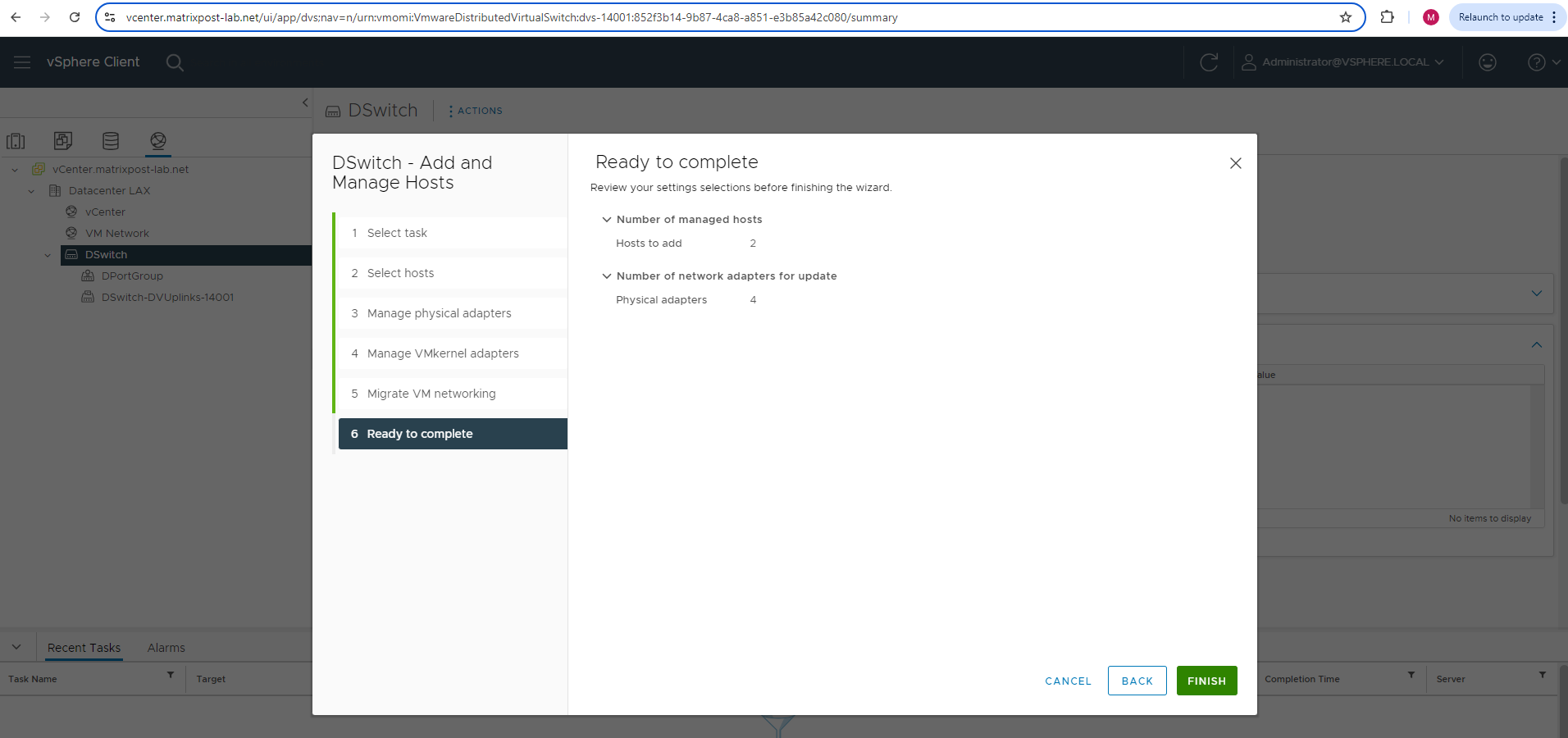
Finally we can click on FINISH to associate this distributed virtual switch to the ESXi Hosts.
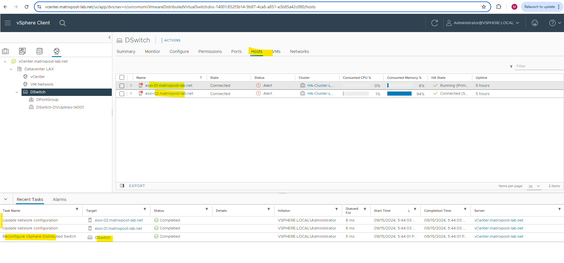
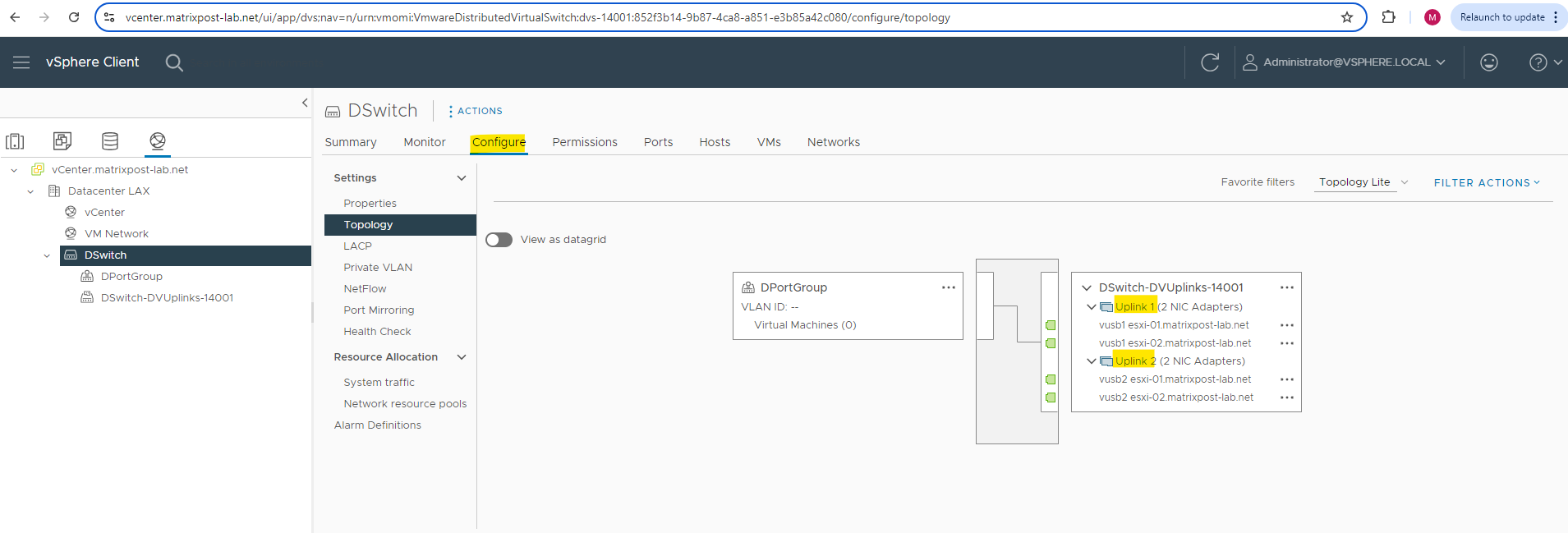
Below we can check the uplink port configuration again to see if the physical NICs are associated correctly. Looks good!
Network Configuration on the ESXi Hosts after associating them to the distributed vSwitch
After deploying and associating this distributed virtual switch to my ESXi Hosts, the networking section on these ESXi Hosts looks like below.
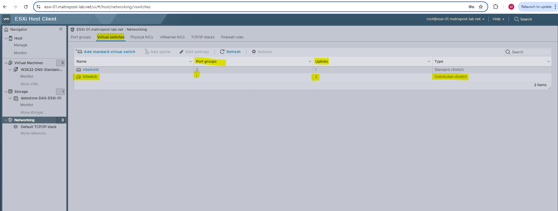
Under virtual switches you can see our newly deployed and associated distributed virtual switch (on the ESXi Host here so called host proxy switch).
When an ESXi host is added to a Distributed Switch, it is given what is called a host proxy switch, which is a switch that resides on every host that is associated with a vSphere Distributed Switch. The host proxy switch replicates the networking configuration set on the vSphere Distributed Switch to the particular host.
Source: https://knowledge.broadcom.com/external/article/324489/networks-not-appearing-on-esxi-host.html
The settings of the distributed virtual switch (so called template) on the vCenter appliance are propagated to all hosts that are associated with the switch.
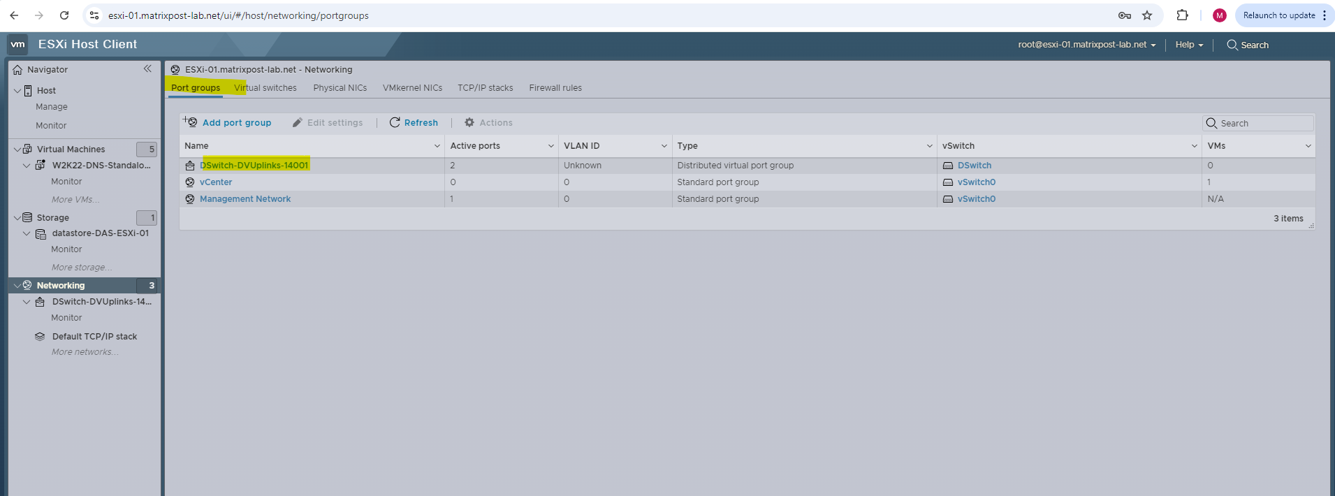
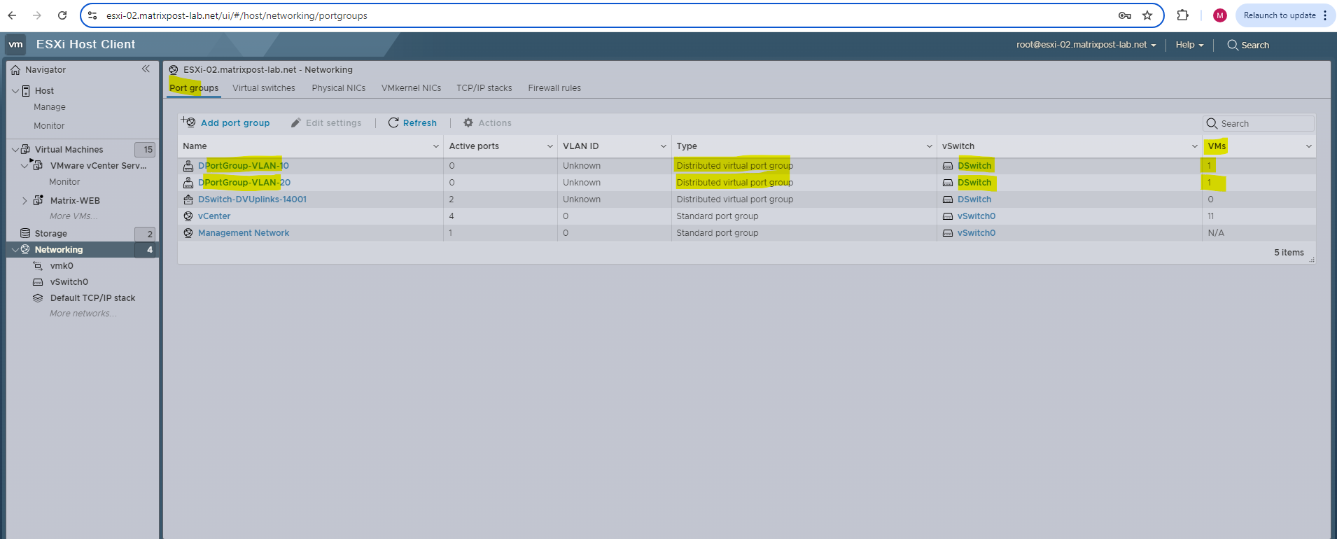
When you navigate to the Port groups section on the ESXi Hosts, you can just see the uplink port group or dvuplink port group, the previously by default created DPortGroup you won’t find here so far. The reason for is that you won’t see distributed ports groups on the ESXi Hosts as long as no virtual machines are connected to them.
This is an expected behavior. When an ESXi host is added to a Distributed Switch, it is given what is called a host proxy switch, which is a switch that resides on every host that is associated with a vSphere Distributed Switch. The host proxy switch replicates the networking configuration set on the vSphere Distributed Switch to the particular host.
The topology diagram of a host proxy switch only shows the adapters attached to the switch ports on the host, and any VMs and vmkernels attached to the Distributed Switch’s port groups. The topology diagram of the host proxy switch does not show port groups of the Distributed Switch if they are unused by the host. The user can see the entire Distributed Switch by viewing the topology of the distributed switch directly.
Source: https://knowledge.broadcom.com/external/article/324489/networks-not-appearing-on-esxi-host.html
Creating Distributed Port Groups
I will now create two distributed port groups on my newly created distributed virtual switch which will be associated to different VLANs to implement and show how network segmentation on layer 2 will work in vSphere environments.
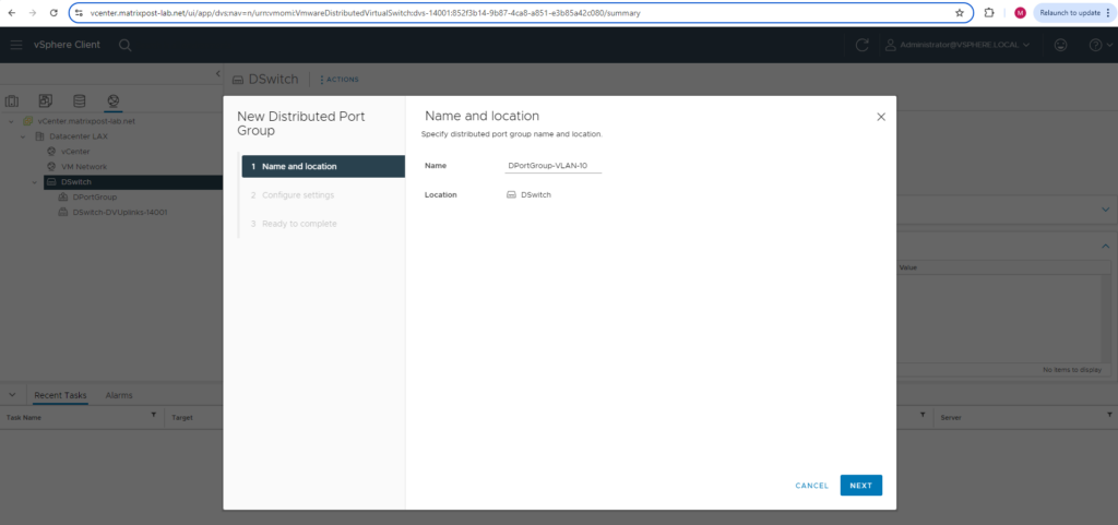
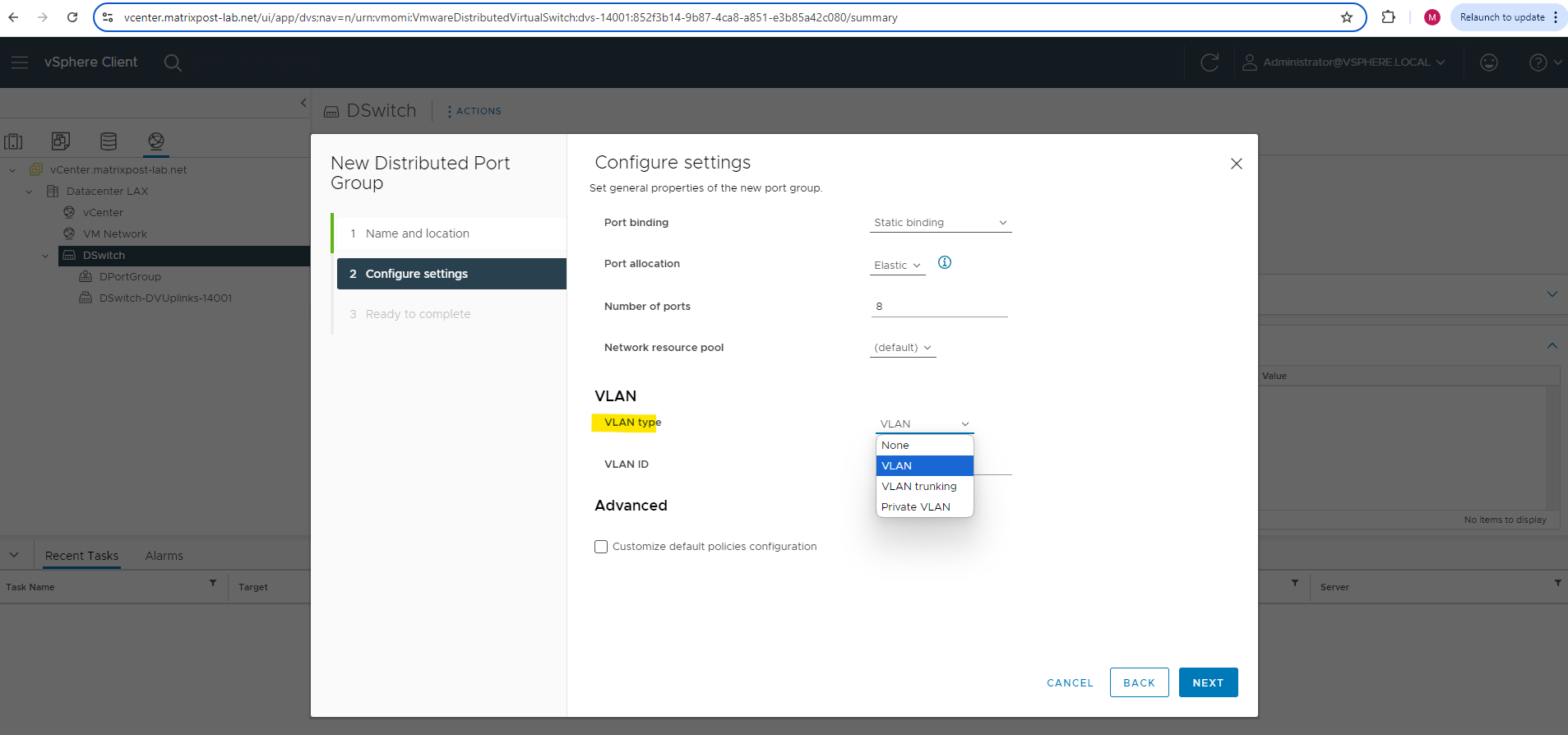
First I will create a new distributed port groups which is configured for VLAN ID 10 and a second for the VLAN ID 20.
For the VLAN type I will use VLAN, we can also configure here VLAN trunking.
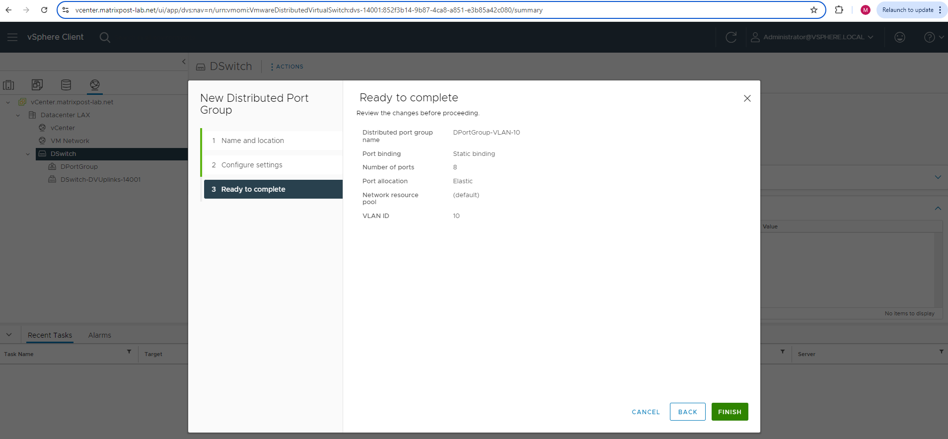
The first distributed port group will be placed into VLAN ID 10.
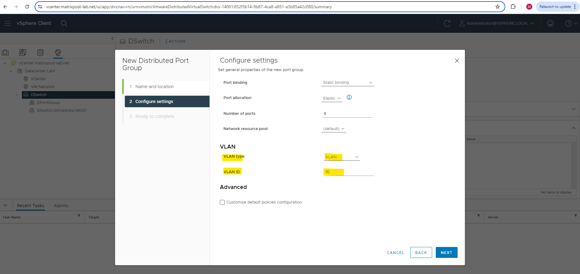
Finally click on FINISH.
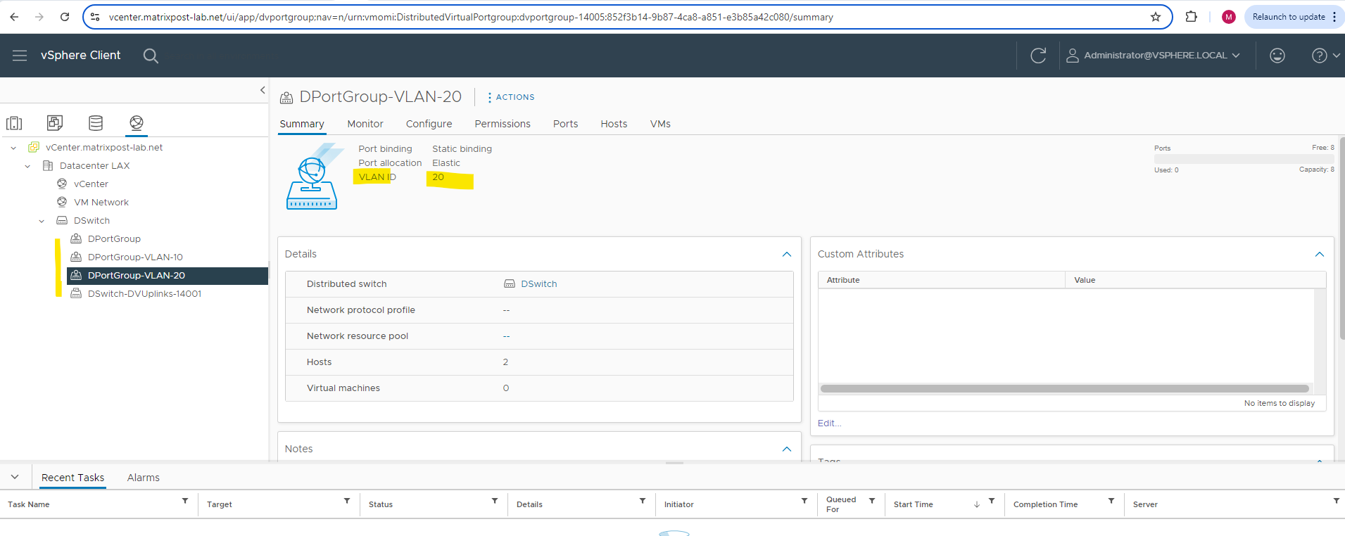
The same I will do for the second distributed port group and configure it for VLAN ID 20.
From now on I can assign these distributed port groups to my virtual machines.
More about virtual local area networks (VLANs), network segmentation, inter-VLAN routing & VLAN ACLs you will find in my following post.
Assign Distributed Ports Groups to Virtual Machines
From now on as mentioned we can assign our distributed port groups to our virtual machines which then will be connected to our distributed virtual switch.
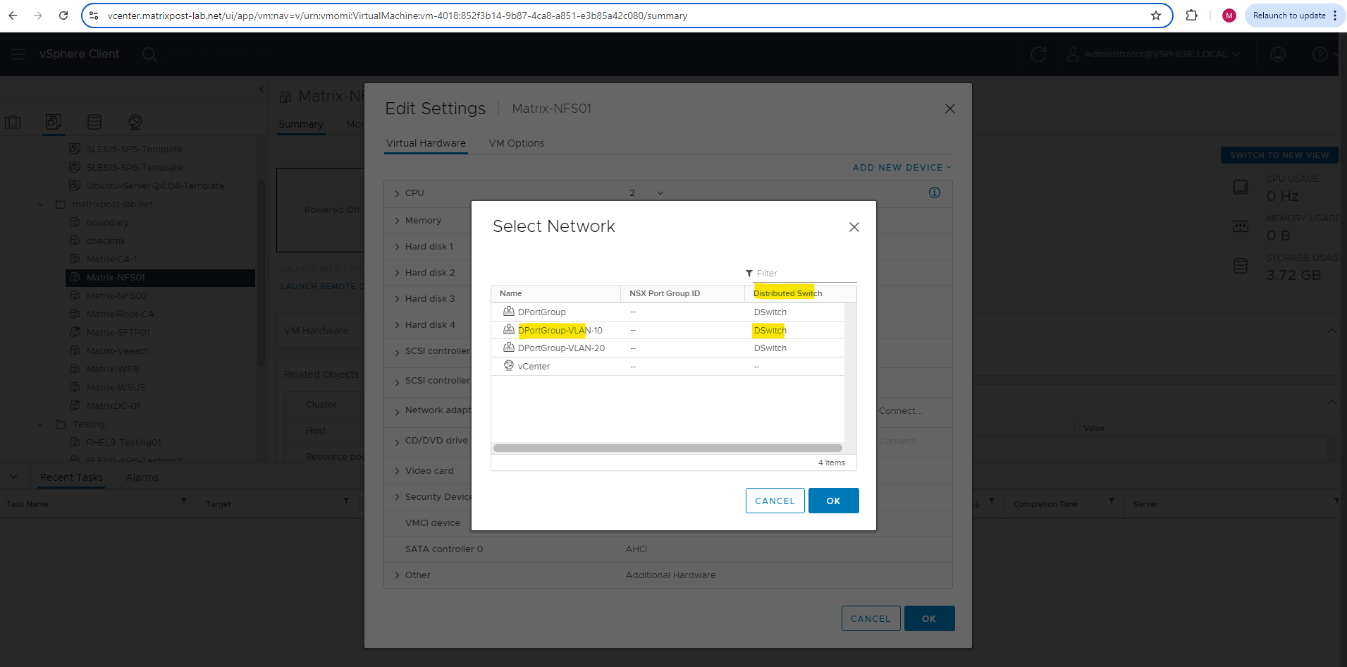
As far as we assign virtual machines to these distributed port groups, they will also appear on the ESXi Hosts network section under Port groups as shown below.
Uplink Port Group by default configured as VLAN Trunk range 0-4094
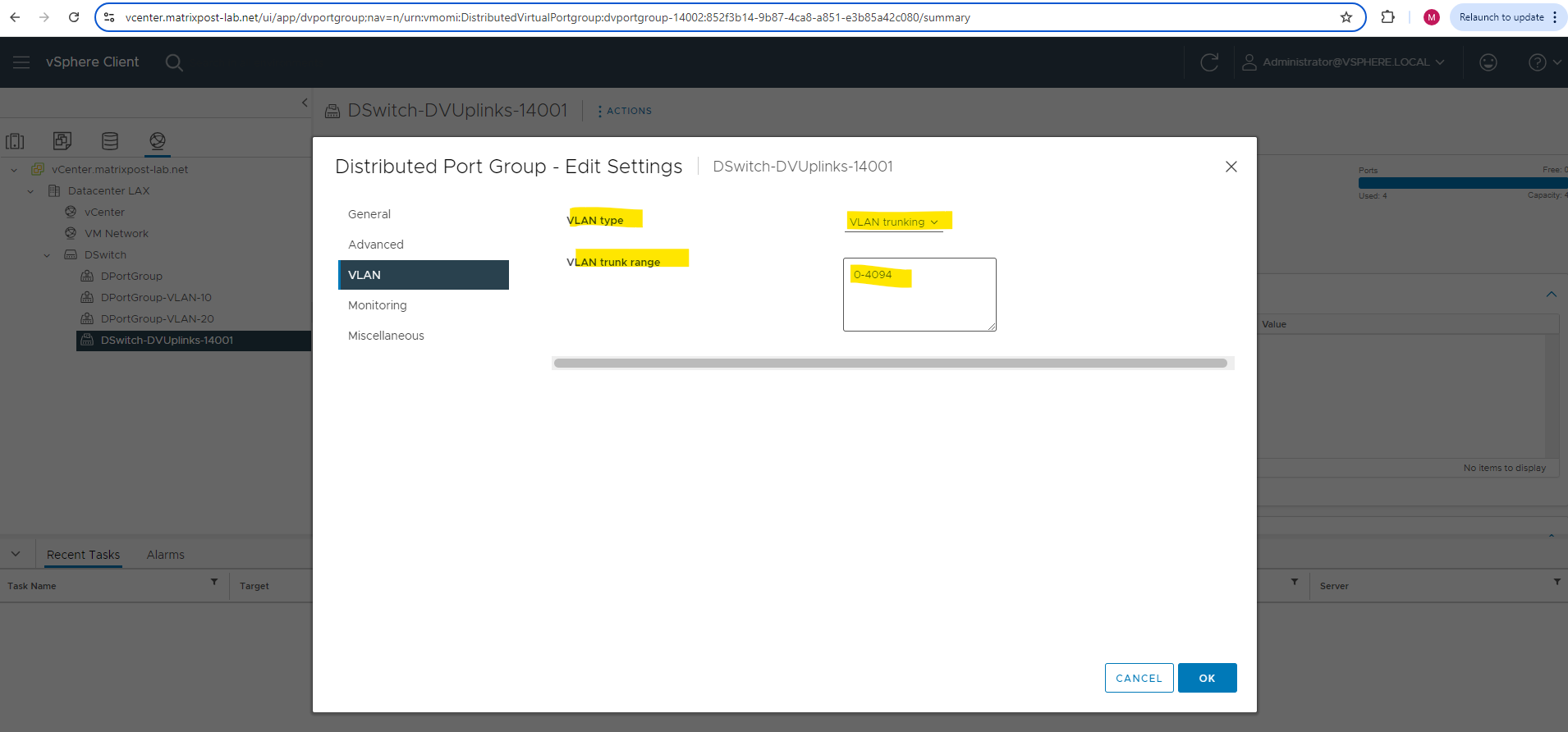
As mentioned already in the introduction, the uplink port group is by default configured for VLAN trunking and the range 0-4094 as shown below.
In case you wonder whats the reason for, the uplink port group will contain our configured uplinks for the distributed virtual switch, which finally will connect the physical NICs of our ESXi Hosts to our distributed virtual switch.
So the uplinks finally are the connection to our physical network (our physical switches to which the NICs of our ESXi Hosts are connected to). Therefore when the uplinks are configured for VLAN trunking and the range 0-4094, finally all traffic, no matter which VLAN ID is used or in case no VLAN is used, will be passed and routed also to our physical network.
Links
vSphere Distributed Switch Architecture
https://docs.vmware.com/en/VMware-vSphere/7.0/com.vmware.vsphere.networking.doc/GUID-B15C6A13-797E-4BCB-B9D9-5CBC5A60C3A6.htmlVMware Distributed Switch Configuration Best Practices
https://www.nakivo.com/blog/vmware-distributed-switch-configuration/Networking Best Practices for vSphere vMotion
https://docs.vmware.com/en/VMware-vSphere/7.0/com.vmware.vsphere.vcenterhost.doc/GUID-7DAD15D4-7F41-4913-9F16-567289E22977.htmlNetworking Best Practices
https://docs.vmware.com/en/VMware-vSphere/7.0/com.vmware.vsphere.networking.doc/GUID-B57FBE96-21EA-401C-BAA6-BDE88108E4BB.htmlExample: Working with a vSphere Distributed Switch
https://docs.vmware.com/en/VMware-NSX-Data-Center-for-vSphere/6.4/com.vmware.nsx.install.doc/GUID-C2909BA6-8F60-46B0-9C96-3EA9683168F7.html
Tags In
Follow me on LinkedIn