Virtual Local Area Networks (VLANs) – Basics about Network Segmentation, inter-VLAN Routing & VLAN ACLs
The main aim of this post is to give you a comprehensive guide and introduction about the basics how VLANs, inter-VLAN routing and VLAN Access control lists (ACLs) will work and how you can configure those VLANs on managed layer 3 switches.
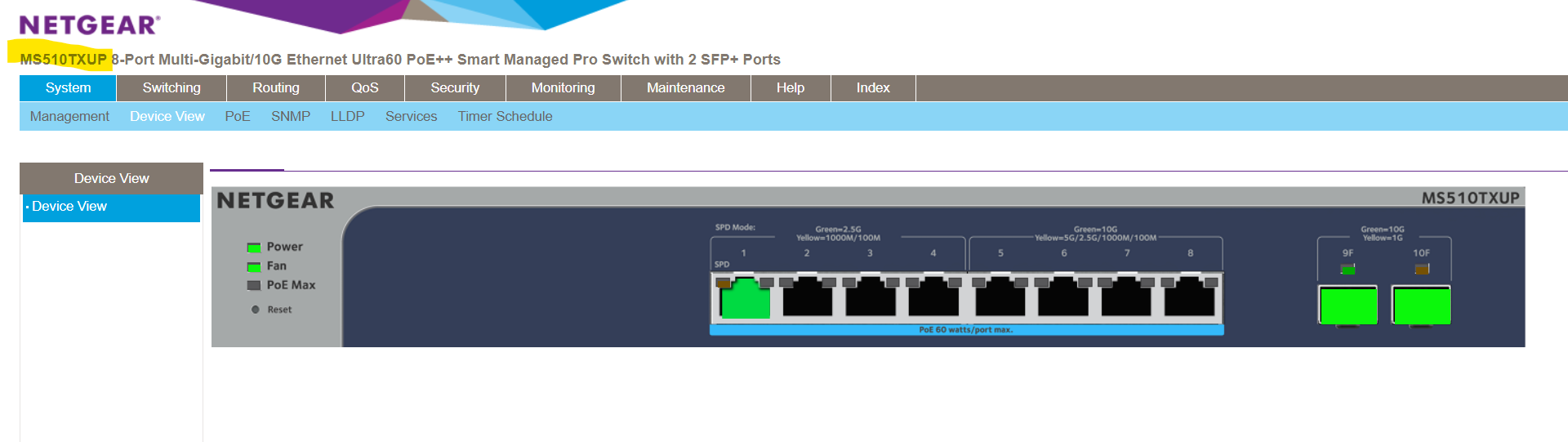
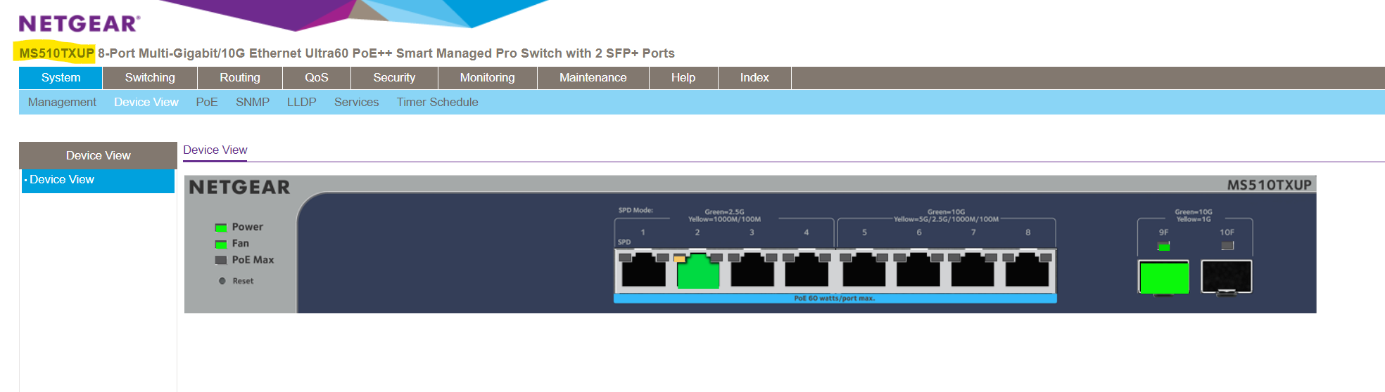
For this post to demonstrate the use of VLANs, I will use a NETGEAR MS510TXUP 8-Port Multi-Gigabit/10G Ethernet Smart Managed Pro Switch resp. two of them connected through a fibre optic connection by using a SFP 10Gigabit Transceiver on each switch connected by a Digitus DK-2533-01-4 – Fibre Optic Cable (Multimode Fibre MMF).
SFP+ 10Gb/s, 10GBase-SR, MMF, 850nm 300M
The AXS85-192-M3 850nm VCESL 10Gigabit Transceiver is designed to transmit and receive serial optical data links up from8.5 Gb/s to 10.51875 data rate over multimode fiber.
(compatible with both 62.5um and 50um LC cables; supports OM1/OM2/OM3/OM4 fiber cables)
https://www.10gtek.com/products/SFP+-10Gb-s-10GBase-SR-MMF-850nm-300M-1.html
Switch 1 connected through a fibre optic connection on port 9 with Switch 2 (also on port 9) which is configured as trunk port to forward data for all configured VLANs (trunk port is a member of all these VLANs) on each switch.
Switch 2
- Introduction
- Configure VLANs on a NETGEAR managed switch
- Inter-VLAN routing on the NETGEAR MS510TXUP Switch
- Filter Traffic on NETGEAR Switches
- Manage the NETGEAR MS510TXUP using the Lite CLI
- Core Switch vs. Edge Switch
- Reset the switch to factory default settings but maintain the registration status
- VXLAN (Virtual Extensible LAN)
- Links
Introduction
A VLAN (Virtual Local Area Network) is a method of logically segmenting a physical network into multiple, isolated networks. Instead of relying solely on physical connections or separate network hardware (e.g. dedicated switches for each single network segment/subnet) to create distinct networks, VLANs enable network administrators to define and manage multiple broadcast domains within a single physical network.
By default most managed switches will have pre-configured all of its ports with the default VLAN ID 1, so all ports on the switch are in the same broadcast domain. Therefore all connected devices are able to communicate to each other out of the box (at data link layer Layer 2 of the OSI model) without the need to first configure the switch.
A VLAN (Virtual Local Area Network) ID is a numerical identifier assigned to a VLAN to distinguish it from other VLANs in a network.
A broadcast domain is a single network segment where all devices within that domain can directly communicate with each other at the data link layer (Layer 2 of the OSI model) using broadcast messages.
Broadcast messages are data packets sent out to all ports (connected devices to that ports) within that single network segment. Devices in the same broadcast domain can therefore efficiently exchange broadcast messages, but these messages do not typically traverse beyond the boundaries of the broadcast domain.
Routers are used to separate broadcast domains, limiting the scope of broadcast traffic and improving network efficiency by reducing unnecessary communication between devices that don’t need to hear the broadcast messages.
Access Ports (Untagged VLAN) vs. Trunk Ports (Tagged VLAN) on Switches
Access ports are used to connect end devices to a specific VLAN mostly used on edge switches (more about edge switches further down), carrying traffic for only that VLAN, while trunk ports are used to interconnect switches, allowing the passage of traffic for multiple VLANs by using VLAN tagging. The specific configuration for access and trunk ports can vary between all the different switch manufacturers.
Access ports can carry traffic for only one VLAN and are unaware of VLAN tags. Any incoming or outgoing traffic on an access port is associated with the VLAN to which the port is assigned (aka PVID see next section).
Trunk ports can carry traffic for multiple VLANs simultaneously. To distinguish between VLANs, trunk ports use VLAN tagging, where each Ethernet frame includes a VLAN tag indicating its VLAN membership.
Trunk ports also known as tagged (T) ports and access ports as untagged (U) ports.
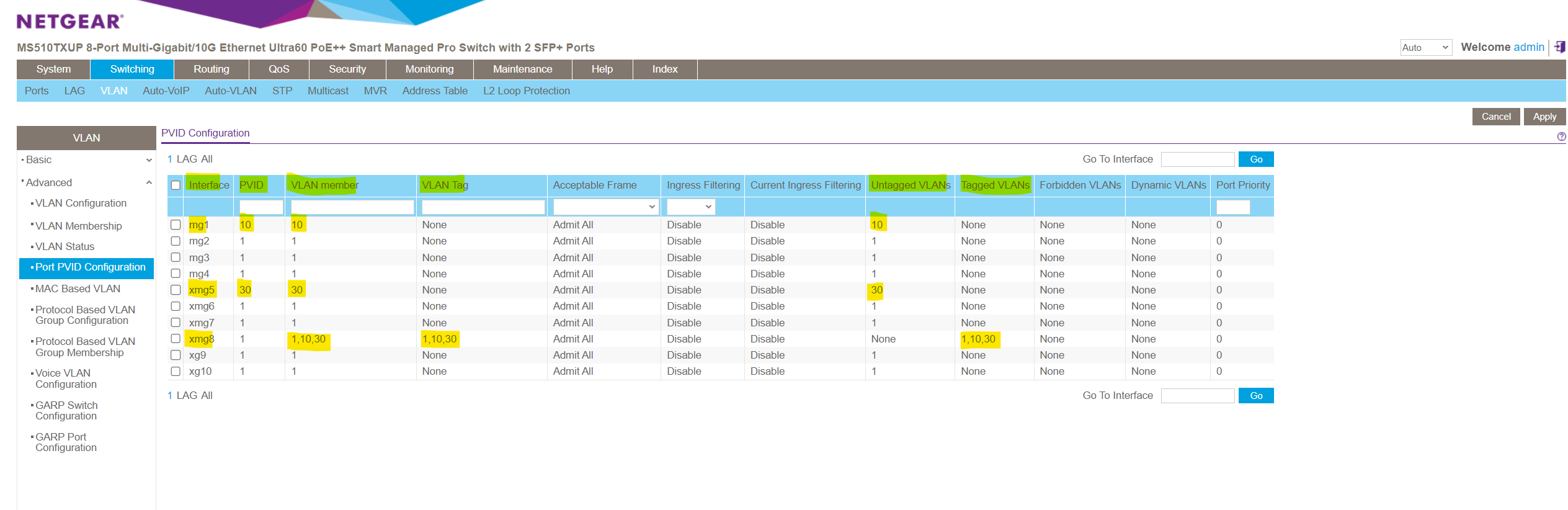
Each trunk port will also have a default native VLAN which is the configured PVID on that port like shown below for the NETGEAR managed switch. The PVID is used for untagged VLANs and you can just associate max one untagged VLAN per trunk port.
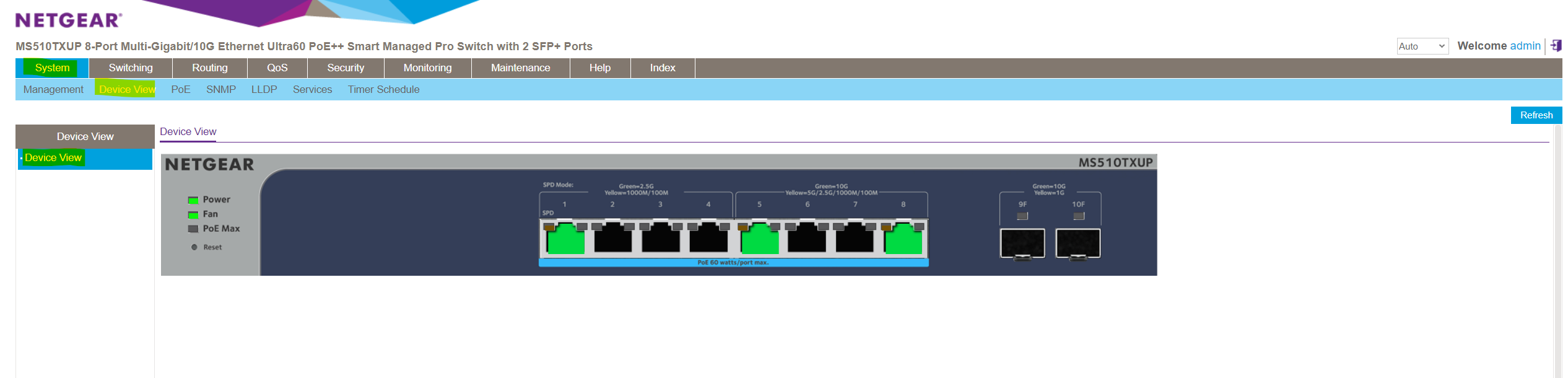
Below for example port 1 and port 5 on the switch are configured as usual access ports (untagged ports) which connects external devices and port 8 as trunk port which can forward traffic for the VLANs 1, 10 and 30 if connected to a different physical switch (interconnect or cascading switches), its default native VLAN is still 1.
PVID (Port VLAN ID) vs. VLAN Membership
The PVID is the VLAN ID assigned to untagged frames received on a switch port. When a switch port receives untagged frames (frames without VLAN tags), the PVID determines the VLAN to which those frames are associated.
The PVID represents the native default VLAN the frames will belong to.
Untagged frames are common in scenarios where devices connected to the port are not VLAN-aware. So for example when a switch port is connected to end devices (such as computers, printers, or IP phones), that are not VLAN-aware and do not tag their frames with VLAN information, the configured PVID on that port ensures that untagged frames are assigned to the correct VLAN.
When a switch port has a specific PVID configured, it means that any untagged frames arriving on that port will be associated with the specified VLAN. However, these frames themselves remain untagged. The VLAN information is applied at the port level without adding an explicit VLAN tag to the frames.
The switch internally processes these untagged frames as part of the specified VLAN, allowing seamless integration of non-VLAN-aware devices into a VLAN-configured network.
Access ports (untagged ports) don’t tag frames at all, much more frames are not tagged in general internally on a switch. Internally the switch just uses untagged frames.
VLAN tags are only used and added to frames which traverses a trunk port in order to get send out to a neighbor switch. These frames must be tagged in order to retain the VLAN information between different switches.
A VLAN membership in contrast refers to the VLAN to which a particular switch port belongs or is assigned to. A device connected to that port must become a member of a VLAN before it can share the broadcast domain with other devices on that VLAN. For untagged access ports this membership is achieved by the assigned PVIDs to as mentioned previously which is the native default VLAN the port belongs to and is member of.
A port can belong to and be a member of multiple VLANs, just in case it is configured as a trunk port and therefore be able to tag the frames to which each of them belongs to. Trunk ports are designed to transmit data for multiple VLANs between switches and routers.
In the figure below we will see that port 8 has tagged VLANs and therefore is a trunk port which is member in the VLANs 1, 10 and 30 and its default native VLAN (PVID) is VLAN 1.
What happens when a Tagged Frame arrives on an Access Port?
Usually you connect end devices like computers, printers, IP phones, etc. to access ports on a switch as mentioned further above.
When these devices send untagged frames (no VLAN is enabled/configured for the NIC of these devices) to an access port, the packets will be associated with the VLAN to which the port is assigned to (the PVID).
When these devices send untagged frames to an trunk port, the packets will be associated with the default native VLAN (PVID) configured on this trunk port.
But what the heck happens if VLAN is enabled and configured on the end device’s NIC, still connected to an access port, now suddenly send tagged frames to this access port?
Well this depends on the manufacturer and specific model or version of the switch you are using.
Usually by design, an access port expects untagged traffic and does not process tagged frames. If a tagged frame arrives on an access port, the switch will typically drop the frame because it does not expect or recognize VLAN tags on an access port.
This behavior is in line with IEEE 802.1Q standards, which specify that access ports should only handle untagged traffic.
In some cases, if the VLAN tag in the frame matches the native VLAN (PVID) configured on the access port, the switch may strip the tag and forward the frame as untagged.
However, this is not standard behavior and depends on the switch’s configuration and vendor implementation.
Best practices is to ensure that devices connected to access ports send untagged frames.
Use trunk ports (which handle tagged frames) when connecting to devices that need to send or receive traffic for multiple VLANs (eg. NICs from Hypervisors like Hyper-V or VMware ESXIs.
Configure VLANs on a NETGEAR managed switch
Below we will see how we can configure a new VLAN on the NETGEAR MS510TXUP 8-Port Multi-Gigabit/10G Ethernet Smart Managed Pro Switch.
Creating a new VLAN
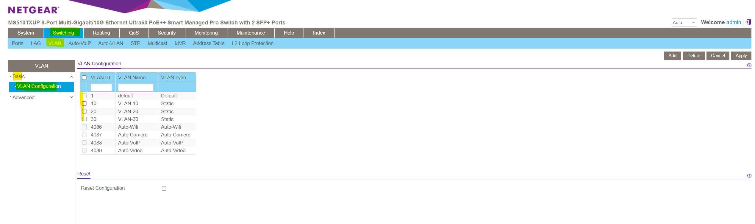
In order to create a new VLAN on this NETGEAR switch we need to navigate to Switching -> VLAN -> Advanced -> VLAN Configuration.
Here by default a new blank top row will appear where we can enter into the VLAN ID field a new ID and besides a new name/description for the VLAN.
The range for VLAN IDs are from 1 to 4095 whereas VLAN 0 and VLAN 4095 are reserved for special purposes.
VLAN 0 is used for priority-tagged frames (802.1p)
VLAN 4095 is often used to represent untagged frames on a trunk port (for some switch vendors)The maximum value of 4096 for VLANs is derived from the structure of the VLAN header in Ethernet frames. The VLAN ID (VID) field in the VLAN header is a 12-bit field. The 12-bit field allows for 2^12 (4096) unique values.
The values range from 0 to 4095, providing a total of 4096 possible VLAN IDs.
I will user here for the new VLAN the ID 10, finally click on Add on the right top. Later I will also add two more VLANs with the ID 20 and 30.
You can use a numbering scheme to allocate VLAN IDs in order to easily identify the purpose of each VLAN.
For example you can use the 3rd octet from a subnet you will assign to a VLAN as VLAN ID like shown below.
10.0.10.0/24 -> VLAN ID 10
10.0.20.0/24 -> VLAN ID 20
10.0.30.0/24 -> VLAN ID 30
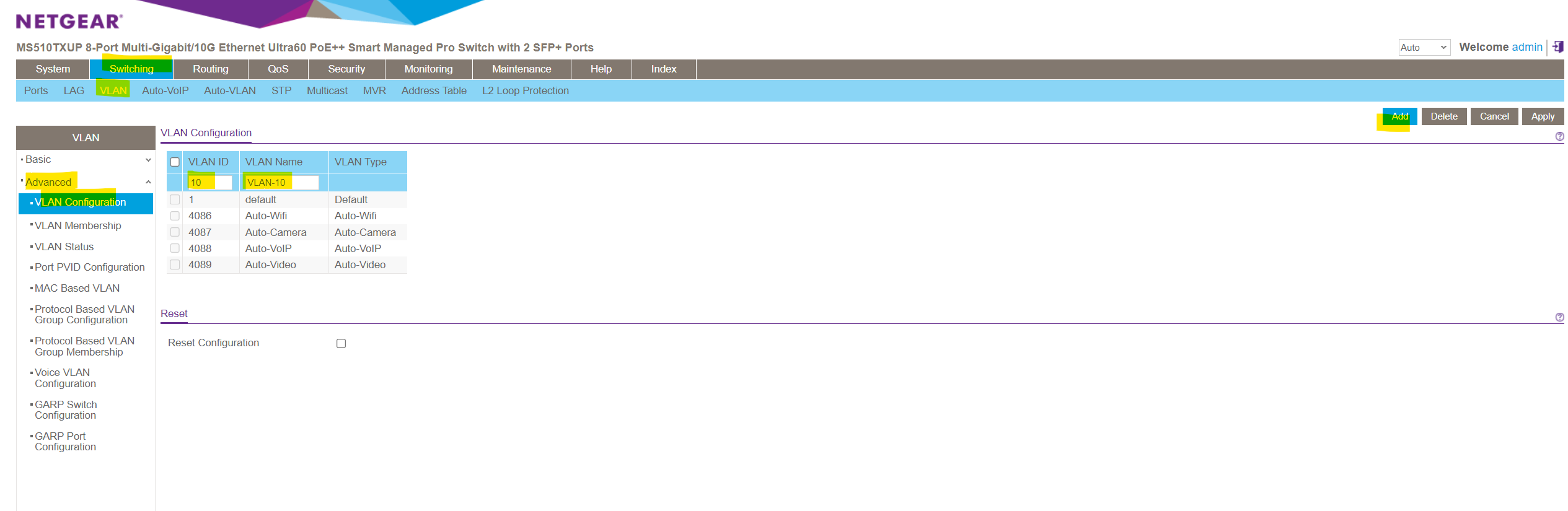
As you can see in the figure above, for managed NETGEAR switches there are by default also further VLANs pre-configured which can’t be used to create a new one.
Default (VLAN ID = 1): Always present
Auto-WiFi (VLAN ID = 4086): Always present
Auto-Camera (VLAN ID = 4087): Always present
Auto-VoIP (VLAN ID = 4088): Always present
Auto-VIdeo (VLAN ID = 4089): Always present
Static: A VLAN that you configured
Dynamic: A VLAN that is created through GVRP registration, that you did not convert to a static VLAN, and that GVRP can therefore remove.
Finally my VLAN configuration will looks like this.
Switching -> VLAN -> Advanced -> VLAN Configuration.
Configure VLAN membership
As already mentioned, by default all ports on the switch are configured as access ports (untagged) and assigned to the default native VLAN ID 1 (PVID).
So by default all ports on the switch are already a member of VLAN 1 and connected devices to all these ports therefore can communicate on data link layer Layer 2 without any further VLAN configuration on the switch.
To configure the VLAN membership for a given port, navigate to the following page on the Device UI.
Switching -> VLAN -> Advanced -> VLAN Membership
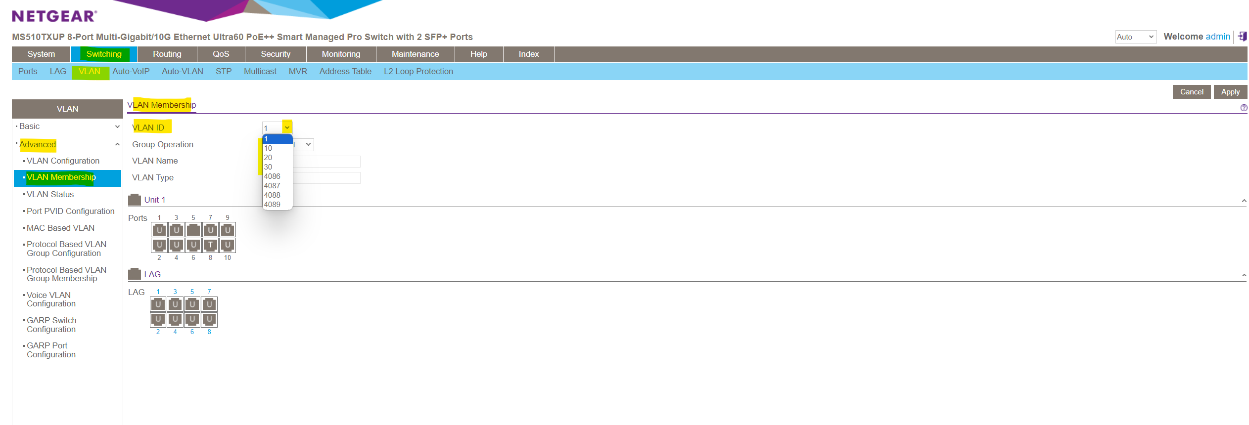
Here we can select either a predefined VLAN or one of our previously new added VLANs within the VLAN Configuration menu. As mentioned, I was adding the VLANs 10, 20 and 30 for testing and demonstration purpose.
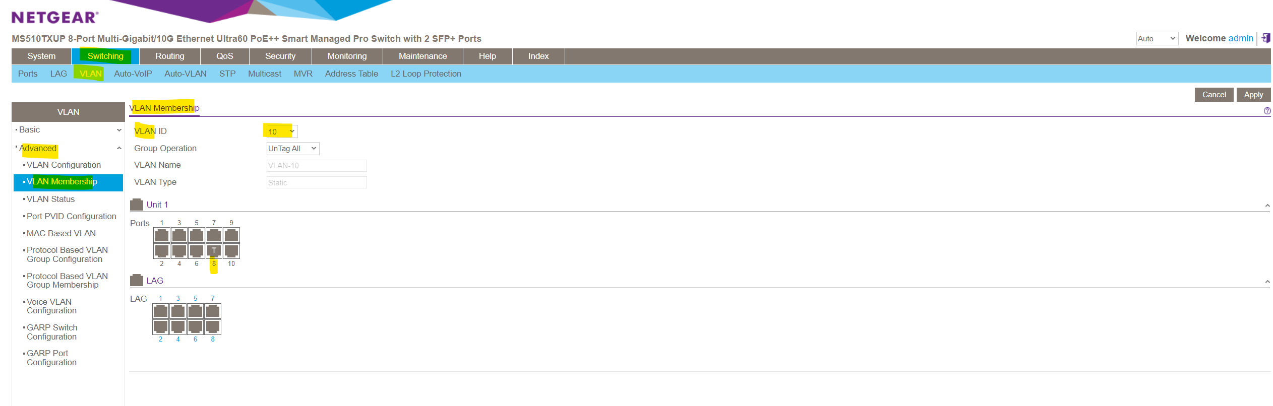
Below for example I will select VLAN 10. As you can see port 8 is already member of this VLAN and also tagged. This port and its associated VLANs (membership) are tagged in order to forward traffic for the VLANs 1, 10, 20 and 30 if connected to a different physical switch, its default native VLAN is still 1.
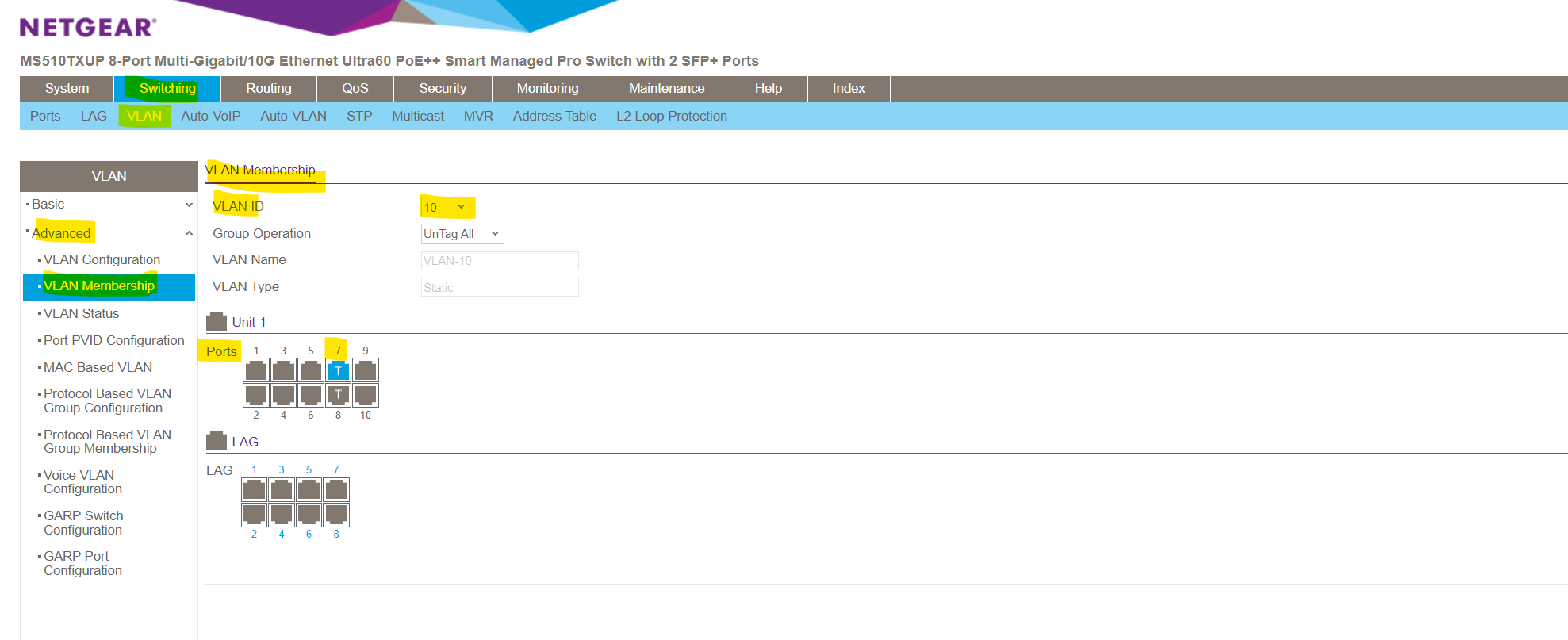
If we now for example also want to add port 7 to be a member of VLAN 10 in order to configure this port also as a trunk, I need to click on this port till it appears as (T) for tagged port and finally need to click on Apply on the right top.
Note!
You can here also configure the membership in multiple VLANs for (U) untagged ports which you should avoid. For all untagged ports that are member of a VLAN, tags are removed from all egress packets and will just be forwarded to the VLAN configured as default native VLAN (PVID) on that untagged ports.
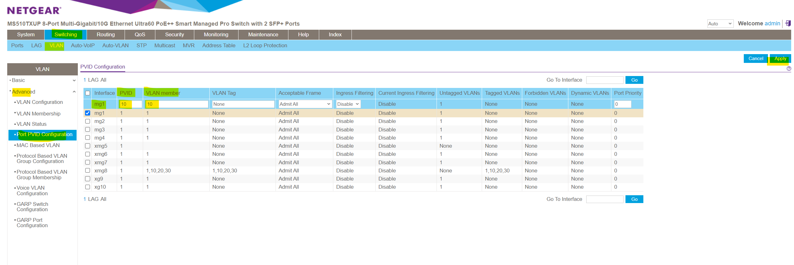
When navigating to Switching -> VLAN -> Advanced -> Port PVID Configuration you will see a summary of all ports and its status. You can also change here the PVID (default native VLAN), the VLAN membership and if its tagged (tag name) or not (None) conveniently.
So here below port 8 is tagged and is member in multiple VLANs. So this port is a trunk port which can be used to interconnect with neighbor switches or routers to forward traffic for different VLANs.
Connect a neighbor switch on the trunk port in order to forward frames (data link layer Layer 2) between the same configured VLANs on different physical switches or connect a router on the trunk port in order to forward packets (network layer 3) between different configured VLANs on the same or between different switches.
Another summary you will see under Switching -> VLAN -> Advanced -> VLAN Status
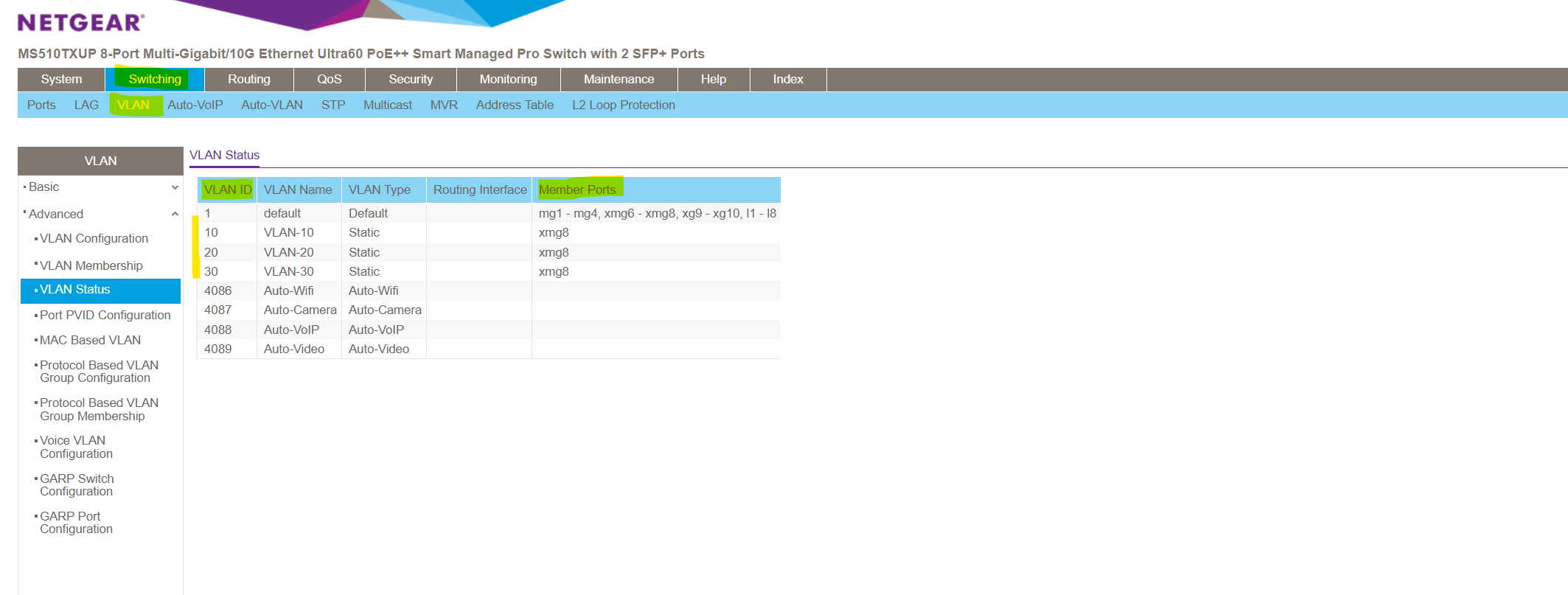
Configure the PVID (default native VLAN) the Port is associated to
As already mentioned, by default all ports on the switch are configured as access ports (untagged) and assigned to the default native VLAN ID 1 (PVID).
If we now want to connect a new device to a port which should be in a specific different default VLAN, we can change this default PVID on the switch by using the Port PVID Configuration menu.
Navigate to Switching -> VLAN -> Advanced -> Port PVID Configuration and select the port you want to change the PVID.
Change the PVID to the new one and also change the VLAN membership, finally click on the right top on Apply. After applying here my port 1 will be associated to the new VLAN 10. From that moment on devices connected to port 1 won’t be able to communicate anymore on data link layer Layer 2 with devices connected to port 2-10 and associated with the different default native VLAN 1. (Except port 8 which is configured as trunk and already member within the VLAN 10).
Communication between those devices from now on needs to be established by using network layer 3 routing, either by using a dedicated router or inter-VLAN routing on layer-3-switches as shown further down.
Inter-VLAN routing on the NETGEAR MS510TXUP Switch
In a nutshell, inter-VLAN routing refers to the process of allowing communication between different VLANs within a network. This routing is typically performed by a router or a layer 3 switch, allowing devices on different VLANs to communicate with each other while still maintaining segmentation and security within the network.
Because this NETGEAR managed switch is a layer3 switch, we can enable routing between all configured VLANs on this switch (inter-VLAN routing) without using any additional routers just out-of-the-box directly on the layer3 switch.
For layer 2 switches they have configured VLANs, you have to use routers either with multiple interfaces where each interface of the router is connected to ports on the switch configured for the different VLANs or with just one interface (so called router-on-a-stick or one-armed router) to enable VLAN routing, just as if multiple LANs were physically isolated.
Drawbacks are additional costs and effort to deploy a dedicated router, further for each VLAN you want to route you will have to provide a dedicated port which can’t be used anymore for other devices, in case of router-on-a-stick at least one port is additionally used.
Generally a layer 3 switch will have much better performance and less latency than a dedicated router because routing is processed directly on the hardware instead of software when using a router.
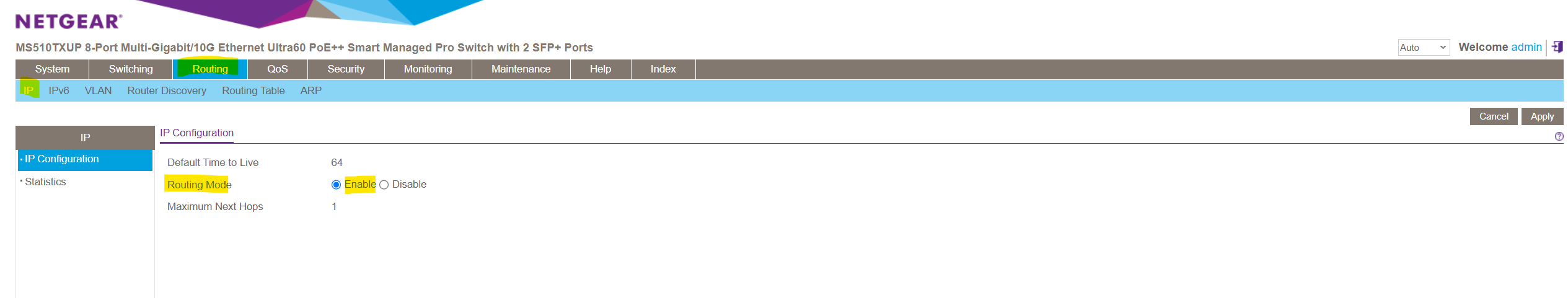
To enable inter-VLAN routing between different VLANs on this NETGEAR managed switch, we first we need to enable in general IP routing on this switch as shown below.
Routing -> IP -> IP Configuration -> Routing Mode -> Enable
The next step for each VLAN on this switch we want to enable inter-VLAN routing for, is to create a dedicated virtual port (so called VLAN routing interface on NETGEAR switches) for each of these VLANs.
On NETGEAR switches, VLAN routing interfaces are often configured by using sub-interfaces. Each sub-interface is associated with a specific VLAN and has its own IP address. This allows the switch to route traffic between VLANs based on the configured sub-interfaces.
Sub-interfaces are provided and used for a variety of purposes by several switch and router manufactures.
In case of our switch, each sub-interface you will create is associated with one dedicated VLAN and has its own IP address. A sub-interface uses the parent physical ports for sending and receiving data. Sub-interfaces will also be used by routers, they just have one physical interface but needs to route traffic between two different networks like for example as mentioned previously when using a router-on-a-stick aka one-armed router for inter-VLAN routing on layer 2 switches.
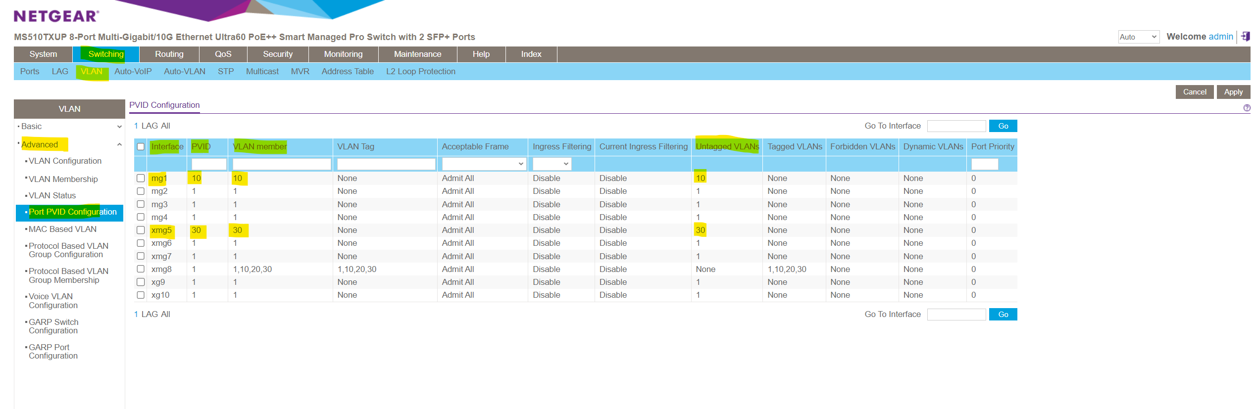
As shown I have already created three different VLANs (10, 20 and 30) on the switch, now I have also configured two ports where I changed the pre-configured default VLAN ID 1.
For port 1 I changed the default VLAN ID 1 into 10 and for port 5 into 30 as shown below.
On both ports the following devices (notebooks) are connected to.
Configuration of the devices as follows:
Port 1 (VLAN 10) -> IP 10.0.10.10 Subnet 10.0.10.0/24
Port 5 (VLAN 30) -> IP 10.0.30.10 Subnet 10.0.30.0/24So far neither a default gateway nor a static route is configured on the devices.
On port 8 btw. my notebook from which I will configure the switch is connected to.
As mentioned for each VLAN we want to enable inter-VLAN-routing we need to create a dedicated virtual port (so called VLAN routing interface on NETGEAR switches or in general a so called sub-interface).
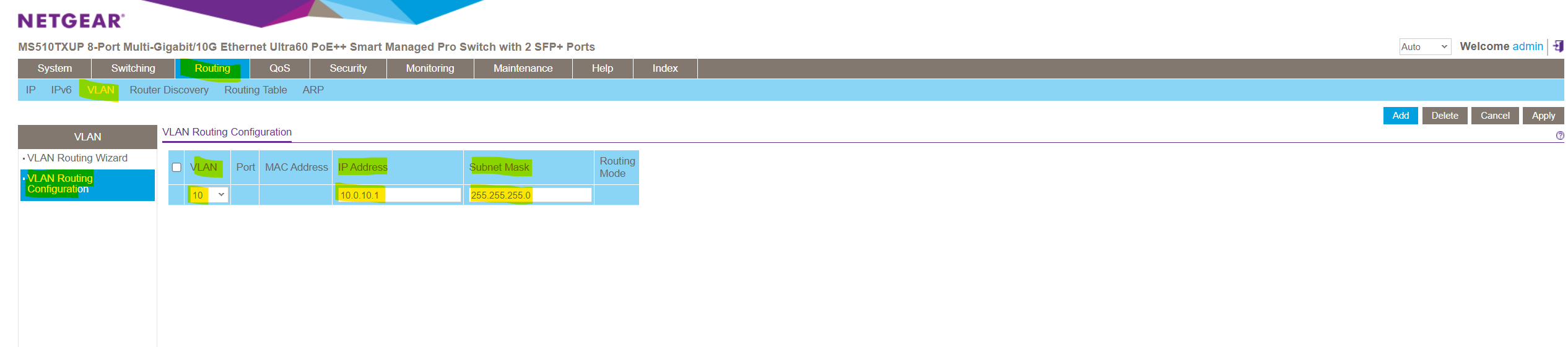
Therefore navigate to Routing -> VLAN -> VLAN Configuration and select the VLAN you want to enable for inter-VLAN-routing.
To create this VLAN routing interface we need to assign an IP address which will act as next hop for the devices within this VLAN to route traffic into different VLANs where also a dedicated VLAN routing interface is configured for.
My subnet within the VLAN 10 is 10.0.10.0/24, for this next hop interface I will use therefore the so far not assigned and available IP address 10.0.10.1.
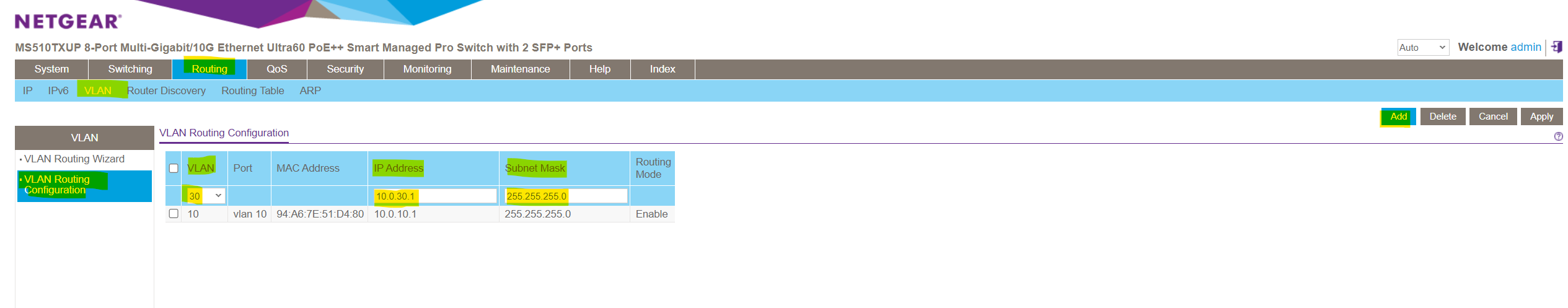
Next I will configure the same for the VLAN 30 where the second device is connected to and I want to enable routing between both. The steps here I think are self-explaining and like previously for VLAN 10.
In the port column we will see the display name of our newly created VLAN routing interfaces (sub-interfaces) for both VLANs we enabled inter-VLAN-routing.
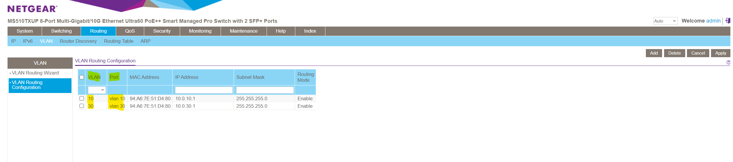
When creating these VLAN routing interfaces (sub-interfaces), by default a new route will be added to the routing table on the switch.
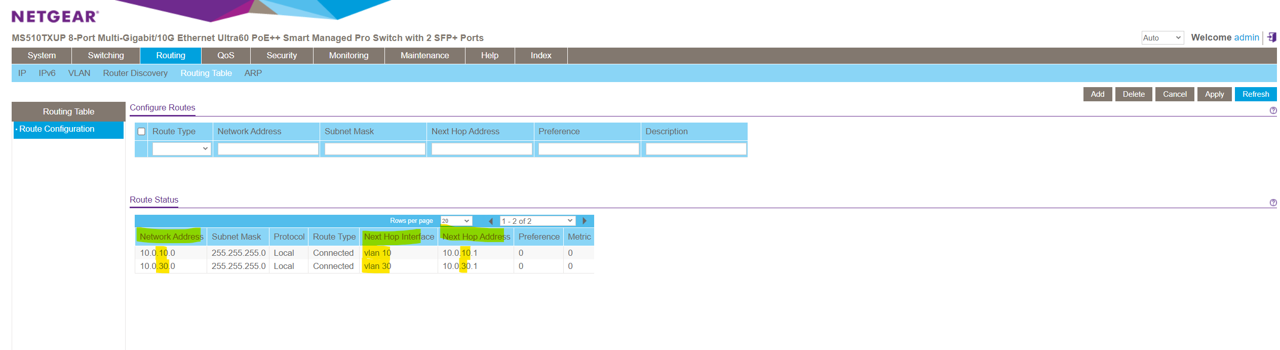
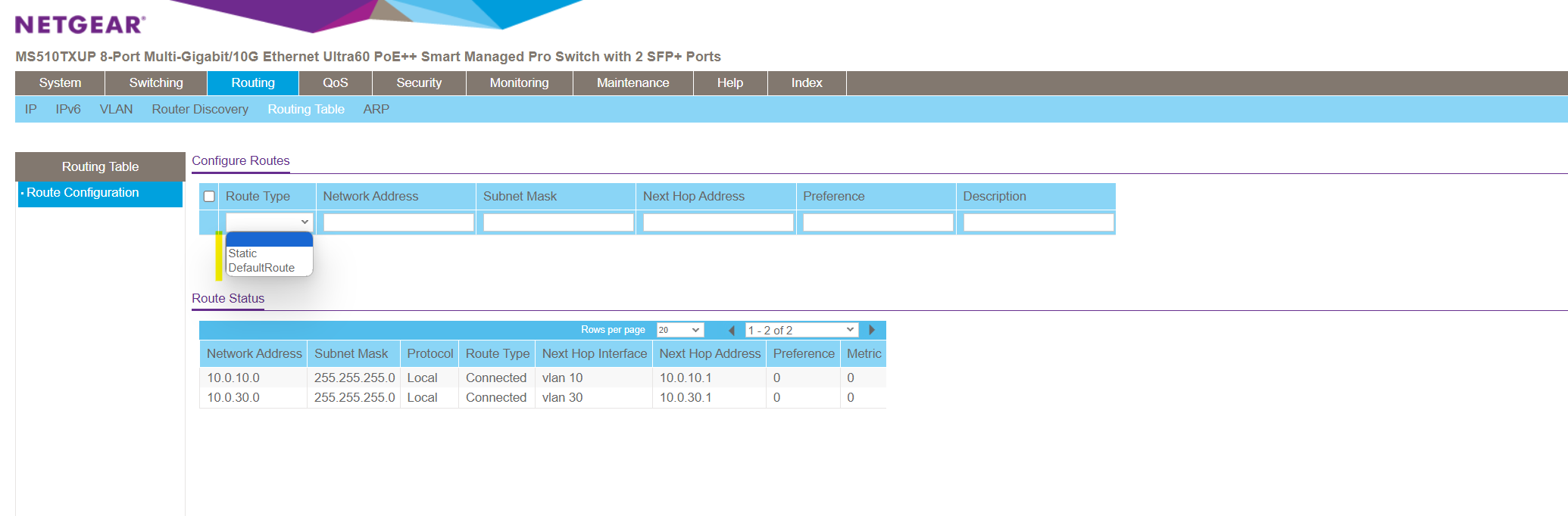
You can also manually add a default or static route to this table.
The default route will be used to route any traffic for which no other route is available for a given IP destination address.
From now on the inter-VLAN-routing configuration on the switch itself is finished, but in order both devices located on those different VLANs can communicate to each other directly, one last final step is needed to be configured on both devices.
On devices connected to VLAN 10 we need to add a static route for the destination VLAN 30 and vice versa. The next hop is always the created VLAN routing interface (sub-interface) resp. its IP address for the VLAN the device itself is connected to. Finally the same as you would use dedicated routers.
Below I will add a permanet static route for the subnet 10.0.10.0/24 on the device which is connected to VLAN 30.
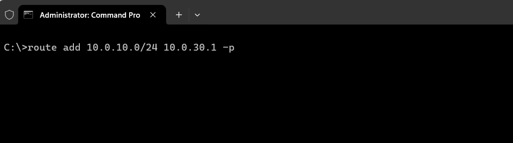
For the device connected to VLAN 10 I need to add a static route for the subnet 10.0.30.0/24.
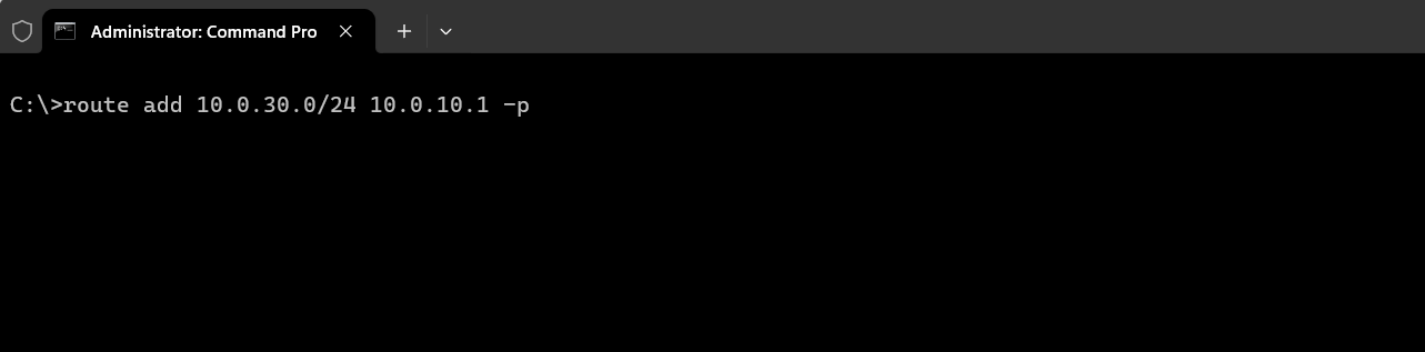
From now on both devices should be able to communicate with each other and traffic should be routed on layer 3 between both VLANs.
Inter-VLAN routing on multiple interconnected NETGEAR Switches
In case we want configure/provision multiple VLANs on multiple NETGEAR switches and also want to enable inter-vlan routing between all those VLANs (e.g. VLAN 10 on switch 1 should be able to send data to VLAN 30 on switch 2), we just need to configure an additional trunk port on each switch and add this port as member to all routed VLANs, finally we need to connect both switches by using those trunk ports.
For those trunk ports you will usually use dedicated SFP (Small Form-factor Pluggable) Ports on each switch to connect to each other by using a fibre optic connection for high performance and less latency as mentioned to the beginning of this post.
AXS85-192-M3 850nm VCESL 10Gigabit Transceiver
Fibre Optic Cable Digitus (Multimode Fibre MMF).
The routing itself we configured previously on just one of both switches, will also work when connecting another NETGEAR switch to by using this trunk port configuration. The VLAN routing interfaces (sub-interfaces) just needs to be configured on one of those interconnected switches.
Filter Traffic on NETGEAR Switches
You can use ACLs to control which hosts can access different parts of a network or to decide which types of traffic are forwarded or blocked on an interface/port.
The direction for packet filtering here on a NETGEAR switch is always inbound (ingress). Therefore you will associate/bind an ACL always directly to the source (port or VLAN) of the traffic to prevent unwanted traffic from traversing your environment.
In order to filter traffic based on IPv4 or IPv6 addresses you need to use the Advanced configuration section below, within the Basic section you can just create ACLs based on layer 2 MAC addresses.
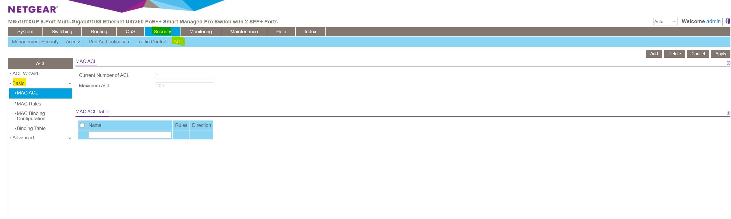
Within the Advanced configuration section you can also configure layer 3 IP ACLs.
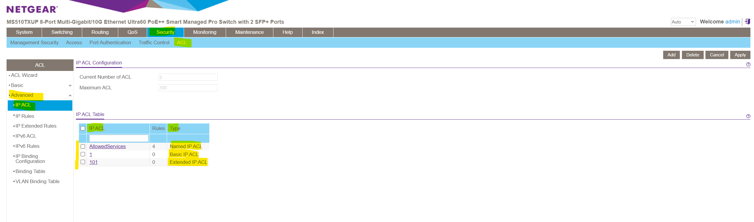
Further there basic or extended IPv4 ACLs. The differences between a basic IPv4 ACL and an extended IPv4 ACL are as follows:
- Numbered ACL from 1 to 99: Creates a basic IPv4 ACL, which allows you to permit or deny traffic from a source IP address.
- Numbered ACL from 100 to 199: Creates an extended IPv4 ACL, which allows you to permit or deny specific types of Layer 3 or Layer 4 traffic from a source IP address to a destination IP address. This type of ACL provides more granularity and filtering capabilities than the basic IP ACL.
- Named IP ACL: Creates also an extended IPv4 ACL with a name string that is up to 31 alphanumeric characters in length. The name must start with an alphabetic character.
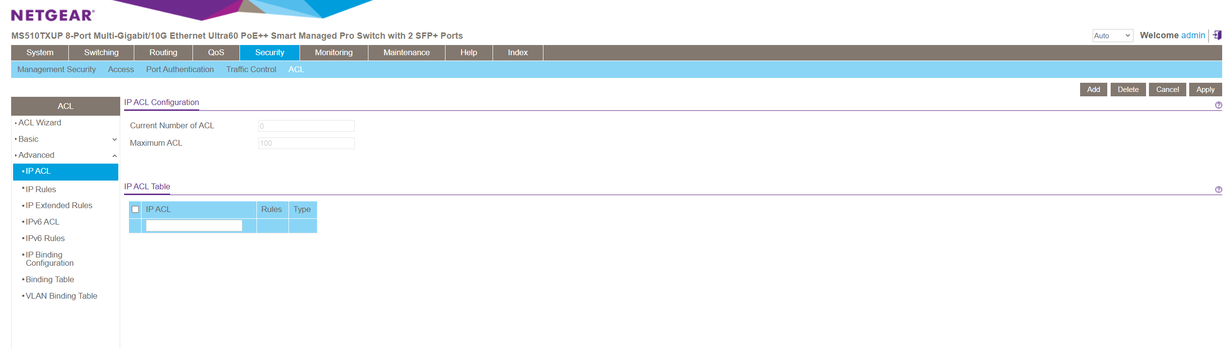
You can create these IPv4 ACLs under Security -> ACL -> Advanced -> IP ACL and enter in the blank top row either a numbered or named ACL as described above.
As explained in the next section, an ACL is a ordered list of classification rules and actions.
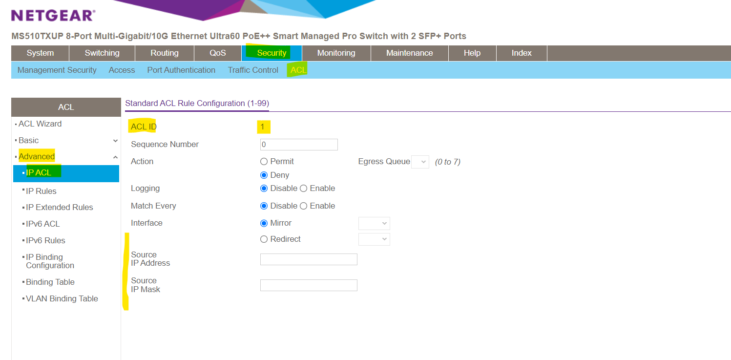
For a basic IPv4 ACL the rule configuration will looks like below. As mentioned, basic IPv4 ACL will allows you to permit or deny traffic just based on the source IP address with no option to filter more granular also for TCP/UDP ports on layer 4.
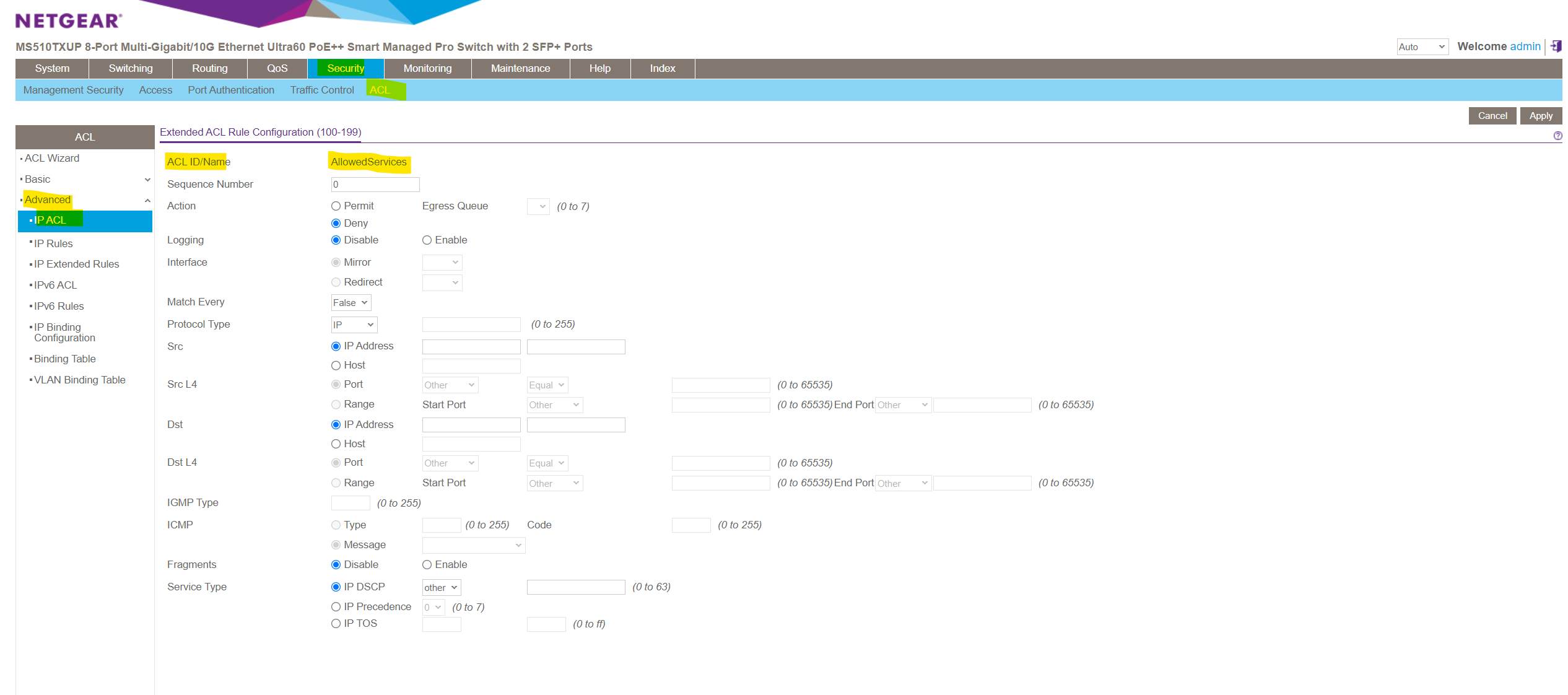
For an extended IPv4 ACL the rule configuration will looks like below. As you can see and mentioned, this type of ACL provides more granularity and filtering capabilities than the basic IP ACL.
Terms
ACL vs. ACE
The Access Control List (ACL) feature is part of the device security mechanism. ACLs enable network managers to define patterns (actions and rules) for ingress traffic. Packets entering the device on a port with an active ACL, are either admitted or denied entry. If they are denied entry, the port can be disabled.
An ACL is a ordered list of classification rules and actions. Each single classification rule, together with its action, is called an Access Control Element (ACE). An ACL must have at least one ACE. Each ACE is made up of filters that determine traffic classifications and associated actions. A single ACL may contain one or more ACE, which is matched against the content of incoming frames. Either a DROP or FORWARD action is applied to frames whose content matches the pattern.
The order of the ACEs within the ACL is significant, since they are applied in a first-fit manner. The ACEs are processed in a sequential manner, starting with the first ACE. When a packet matches an ACE classification, the ACE’s action is taken and then that ACL’s processing is stopped. If the packet does not match, the next ACE is processed. If all ACEs of an ACL have been processed without finding a match and if another ACL exists, it is processed in a similar manner (ACLs are not ordered in a way).
Note !
If no match is found to any ACE in all relevant ACLs, the packet is dropped (as a default action). The default drop action requires explicitly enabling all permitted traffic, including management traffic, such as telnet, HTTP or SNMP that is directed to the router itself.
Wildcard Mask
A wildcard mask is similar to a subnet mask but the reverse.
An IPv4 ACE uses a 32-bit wildcard mask to determine which bits of the address to examine for a match. Wildcard masks are also used by the Open Shortest Path First (OSPF) routing protocol.
A wildcard mask is similar to a subnet mask in that it uses the ANDing process to identify which bits in an IPv4 address to match. However, a wildcard mask and a subnet mask differ in the way they match binary 1s and 0s. Unlike with a subnet mask, in which binary 1 is equal to a match, and binary 0 is not a match, with a wildcard mask, the reverse is true.
Wildcard masks use the following rules to match binary 1s and 0s:
- Wildcard mask bit 0: Match the corresponding bit value in the address.
- Wildcard mask bit 1: Ignore the corresponding bit value in the address.
Source: https://www.ciscopress.com/articles/article.asp?p=3089353&seqNum=5
For example, if you have an IP address of 192.168.1.0 and a wildcard mask of 0.0.0.255, it means that any IP address where the first three octets are the same as 192.168.1 will match the rule, regardless of the value in the fourth octet.
Here’s a quick breakdown:
- IP Address: 192.168.1.0
- Wildcard Mask: 0.0.0.255
This allows any value in the last octet (0-255) to match, making it a wildcard. So, 192.168.1.1, 192.168.1.2, …, 192.168.1.255 would match this rule.
Another example are host wildcard masks, when you want to specify a single host rather than a range of IP addresses. A host wildcard mask is essentially a more specific form of a wildcard mask, indicating that only a particular IP address should match.
For example, consider the following:
- IP Address: 192.168.1.5
- Host Wildcard Mask: 0.0.0.0
In this case, the host wildcard mask is set to all zeros (0.0.0.0), which means that only the exact IP address 192.168.1.5 will match the rule. This is because each bit in the mask is set to 0, indicating an exact match for the corresponding bit in the IP address.
So, with a host wildcard mask of 0.0.0.0, only the IP address 192.168.1.5 will match, and no other IP address in the 192.168.1.x range would satisfy the condition.
Using ACLs to control Traffic Flow
Access control lists (ACLs) ensure that only authorized users can access specific resources while blocking any unwarranted attempts to reach network resources. ACLs are used to provide traffic flow control, restrict contents, decide which types of traffic are forwarded or blocked, and provide security for the network.
The NETGEAR managed switch supports a total of 100 ACLs, which can be a combination of MAC ACLs, basic IPv4 ACL, extended IPv4 ACLs, and IPv6 ACLs.
Source: https://www.downloads.netgear.com/files/GDC/MS510TXM/MS510TXM_MS510TXUP_UM_EN.pdf
About how to configure these ACLs in detail on the NETGEAR managed switch you can use the PDF above or under the following page, further down I will just show one simple example to filter traffic by using IP ACLs to filter layer 3 traffic.
Using IP ACLs to filter Layer 3 Traffic Flow
IP ACLs classifies layer 3 traffic. Each ACL is a set of up to 10 rules applied to inbound traffic.
Therefore when traffic will flow inbound (ingress) from a source like e.g. a connected end user device to the switch (and associcated VLAN to a specific port), it will get filtered and dropped directly at the port before it enters the VLAN and therefore will not get forwarded and processed within the switch internally and its backplane as usually for traffic that is allowed to enter the VLAN.
Each rule specifies whether the contents of a given field should be used to permit or deny access to the network, and can apply to one or more of the following fields within a packet:
- Source IP address
- Destination IP address
- Source Layer 4 port
- Destination Layer 4 port
- ToS byte
- Protocol number
Note that the order of the rules is important: When a packet matches multiple rules, the first rule takes precedence.
Each ACL further has an implicit (not shown in the rules list) deny all rule by default at the end of an ACL rule list. That is, if an ACL is applied to a packet and none of the explicit rules match, then the final implicit deny all rule takes effect and the packet is dropped.
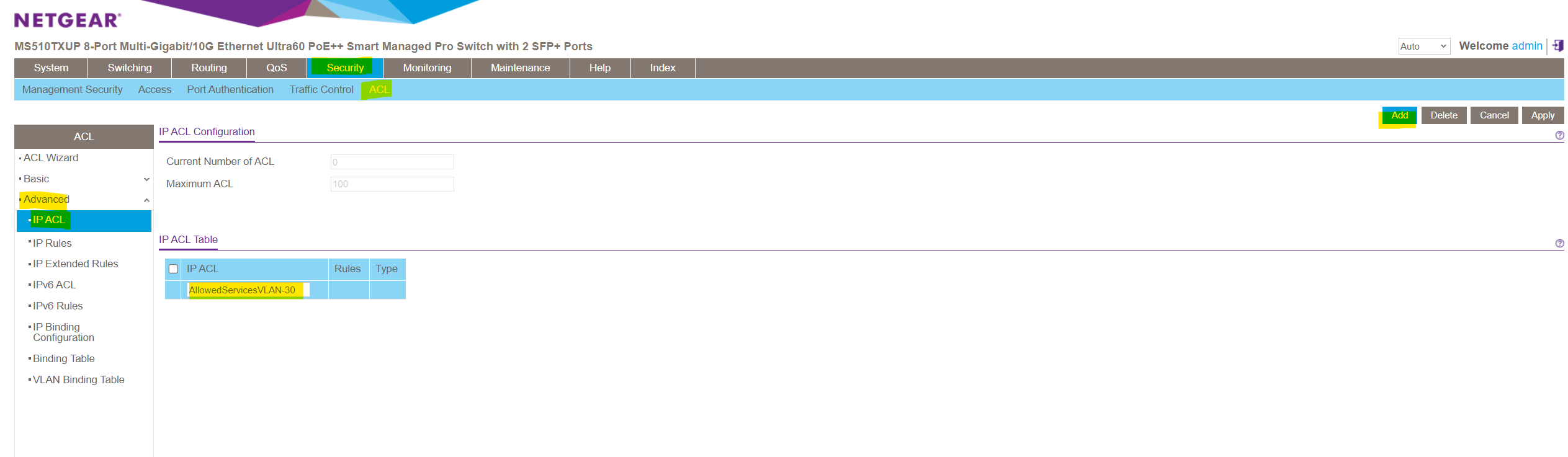
Security -> ACL -> Advanced -> IP ACL
Enter a name for the new IP ACL and click on Add on the right top. Here for example I will create a new ACL which I will associate later to VLAN 30 in order to restrict traffic allowed for this VLAN. Alternatively you can also associate ACLs just to separate ports instead to a complete VLAN.
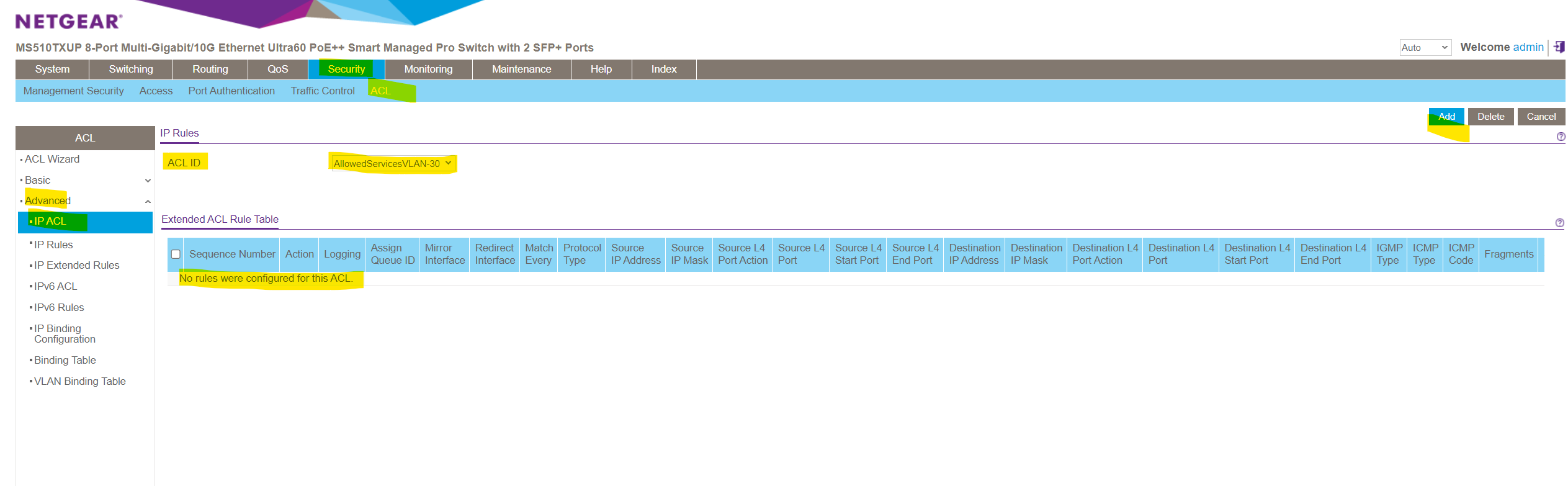
The new IP ACL is added but so far doesn’t include any deny or permit IP Rules.
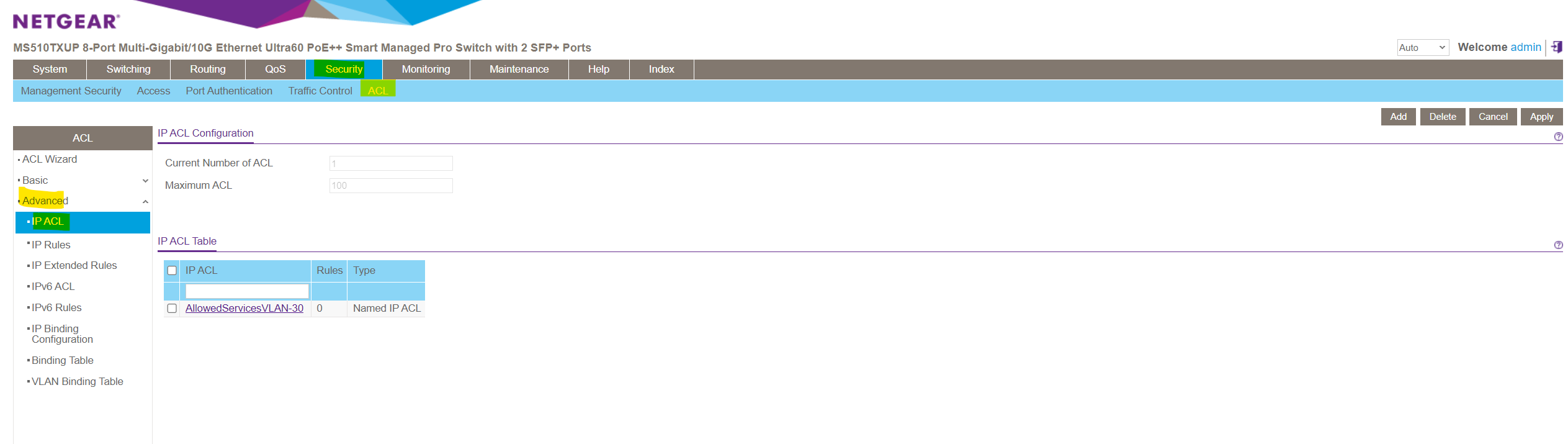
We can add some extended IP Rules within the Security -> ACL -> Advanced -> IP Extended Rules menu.
Here click on Add.
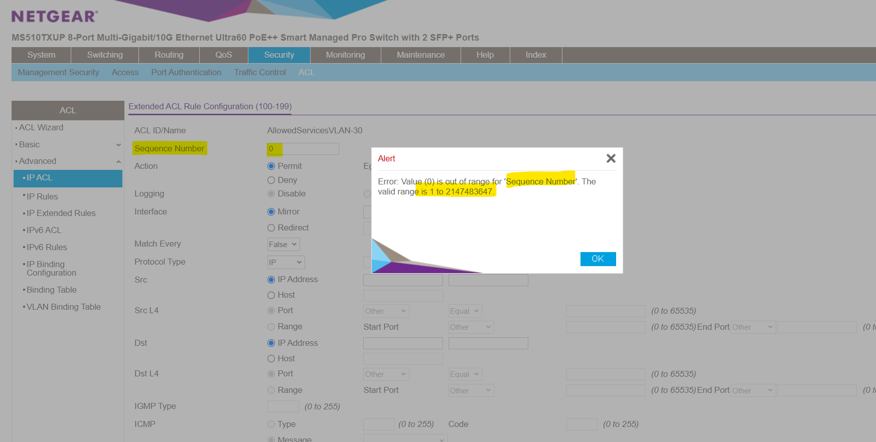
First of all in order to add a new IP Extended Rule you must assign a new valid Sequence Number in the range of 1 to 2147483647.
And remember!
The order of the ACEs within the ACL is significant, since they are applied in a first-fit manner. The ACEs are processed in a sequential manner, starting with the first ACE. When a packet matches an ACE classification, the ACE’s action is taken and then that ACL’s processing is stopped. If the packet does not match, the next ACE is processed.If no match is found to any ACE in all relevant ACLs, the packet is dropped (as a default action). The default drop action requires explicitly enabling all permitted traffic, including management traffic, such as telnet, HTTP or SNMP that is directed to the router itself.
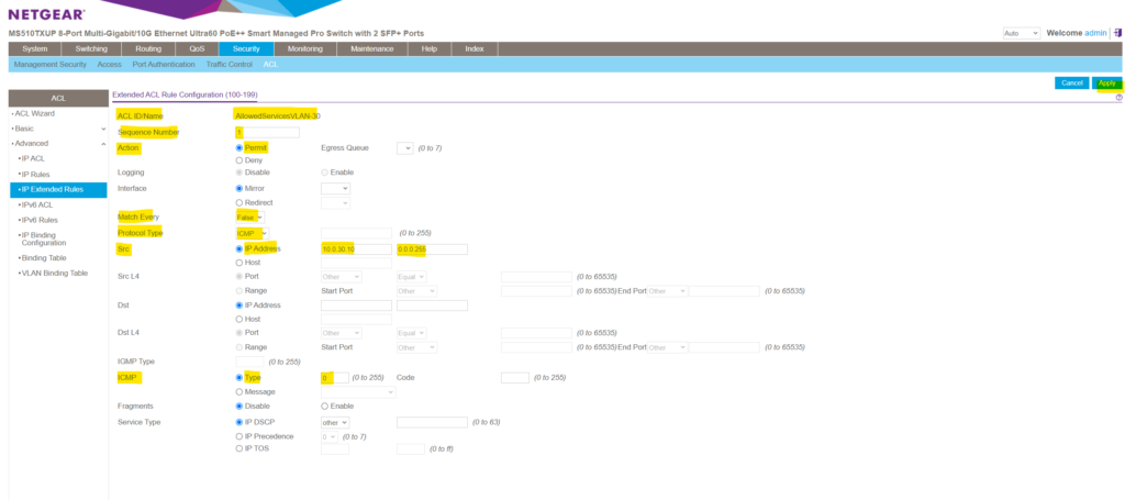
For the first rule aka Access Control Element (ACE), I will allow ICMP Echo Request and Reply messages (aka Pings).
Each single classification rule, together with its action, is called an Access Control Element (ACE)
Here I will first enter a new seqence number starting with 1. Then under Action I choose to permit traffic for this rule. Under match every I will leave by default False, otherwise all packets must match the rule and other rules are not considered.
For the protocol type I will need to select ICMP. Then I want to apply this rule to traffic originated by the VLAN 30 which is associated to the subnet 10.0.30.0/24. To match traffic for a /24 subnet we need to enter here the wildcard mask 0.0.0.255 as mentioned further above.
Finally I don’t want to allow all ICMP traffic, just ICMP Echo Request and Reply messages (aka Pings). First select Type under ICMP and then for ICMP Echo Request I need to enter the type 8 and for reply type 0.
ICMP Type Numbers
https://www.iana.org/assignments/icmp-parameters/icmp-parameters.xhtml
Finally we add the rule by clicking on Apply.
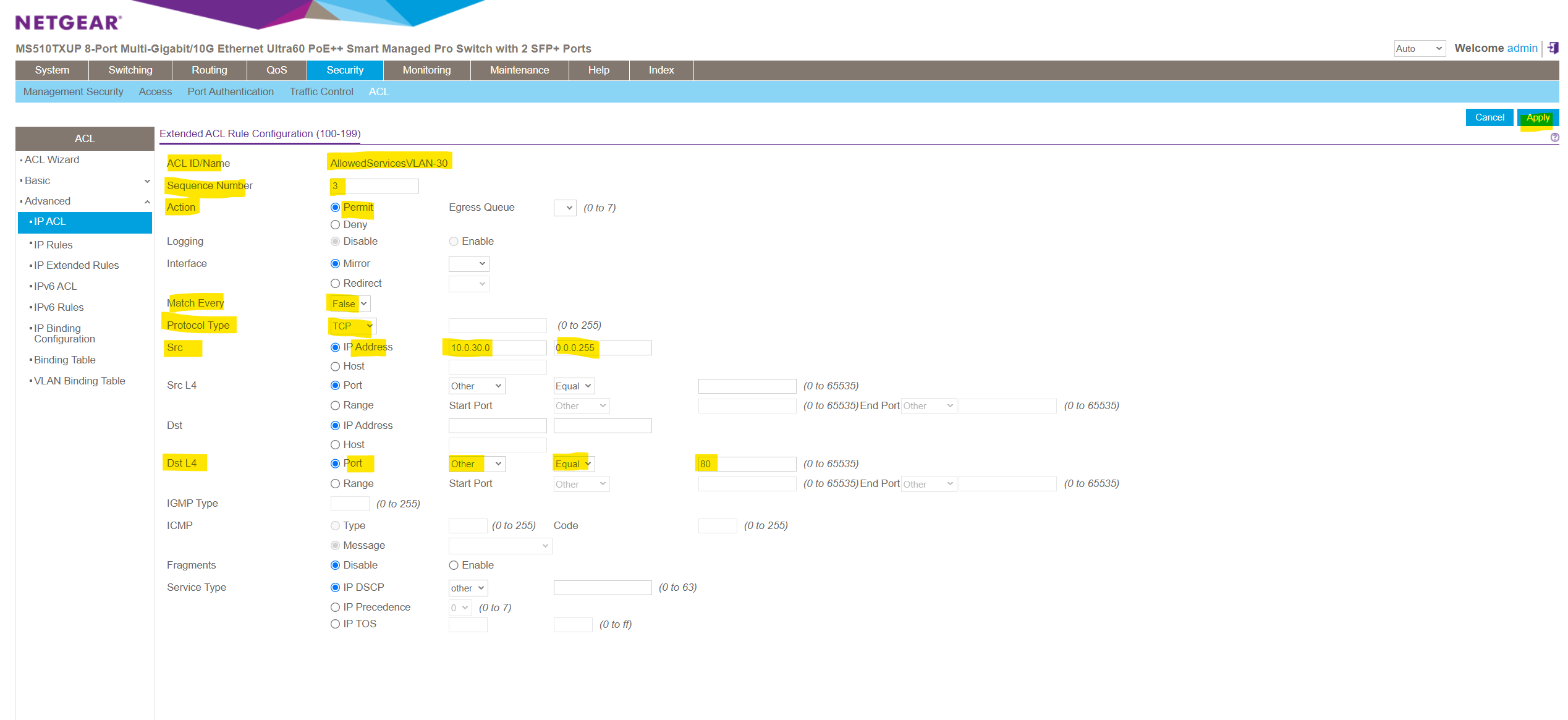
Next I will add three more rules to also allow ICMP Echo Request messages which had type 8 and layer 4 TCP/IP traffic for the HTTP port 80 and HTTPS port 443 protocol.
Here I will add the TCP HTTP port 80 permit rule.
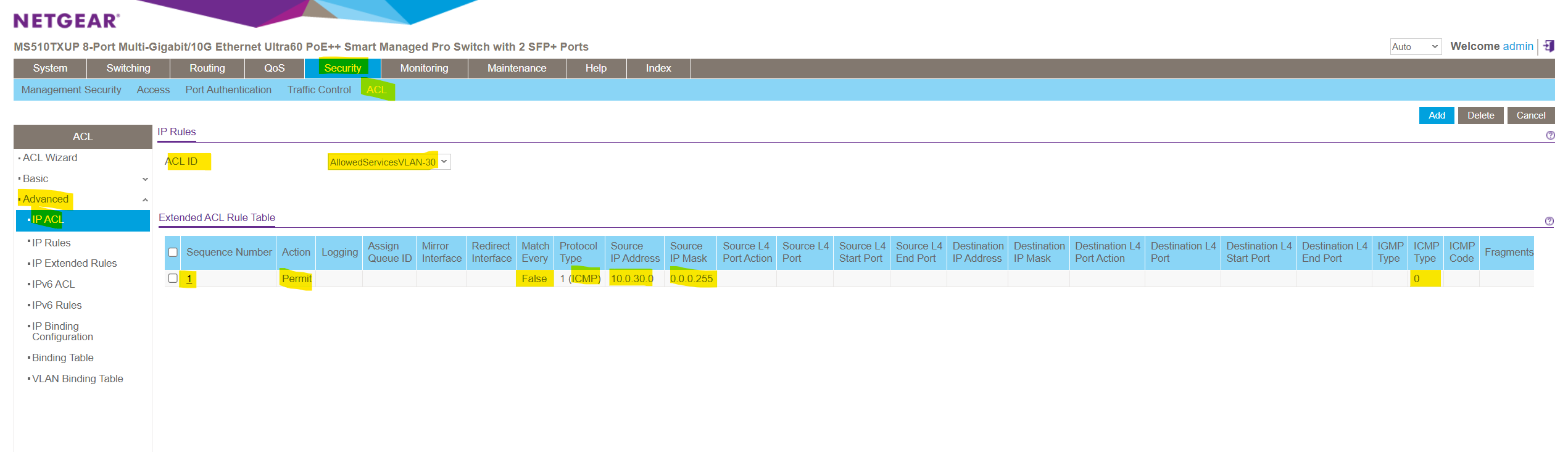
Finally the ACL and all its ACEs (rules) will looks like this.
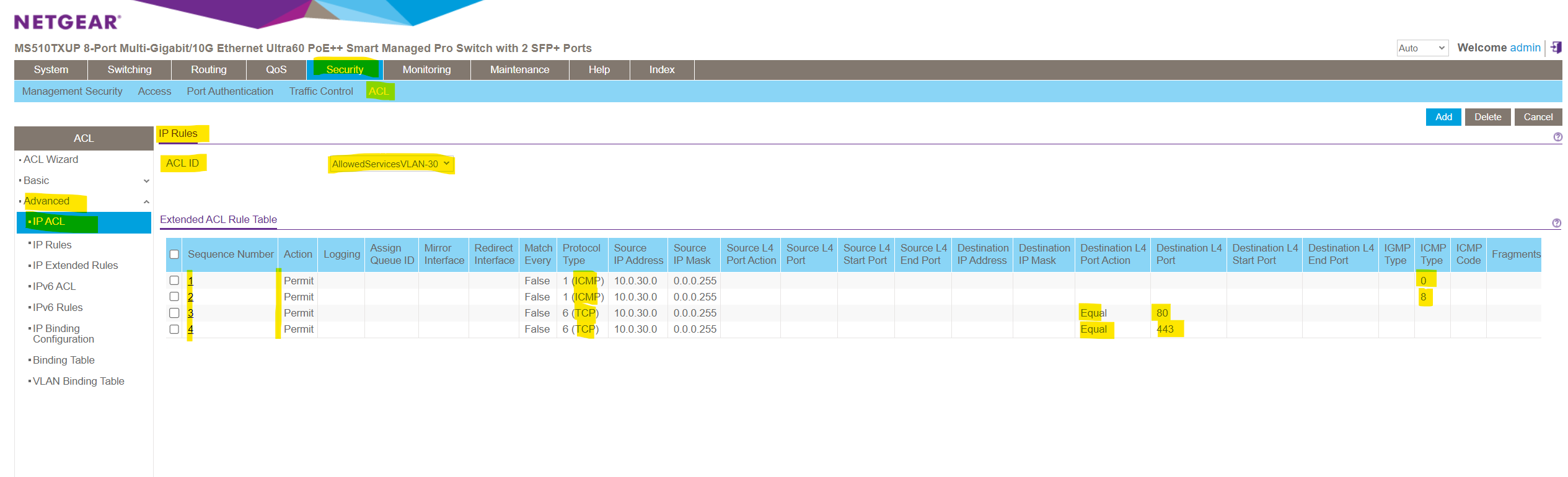
So far we just created all the rules which traffic is permitted to enter a VLAN and what traffic is denied and will be dropped. As mentioned I want to use these rules to filter traffic on VLAN 30 and therefore for my subnet 10.0.30.10/24.
To finally apply these rules and therefore will be enabled and active for VLAN 30, we can either associate the ACL on just dedicated ports for specific devices connected to VLAN 30 or we can associate the ACL directly to a VLAN and therefore by default to all ports which are member of the associated VLAN.
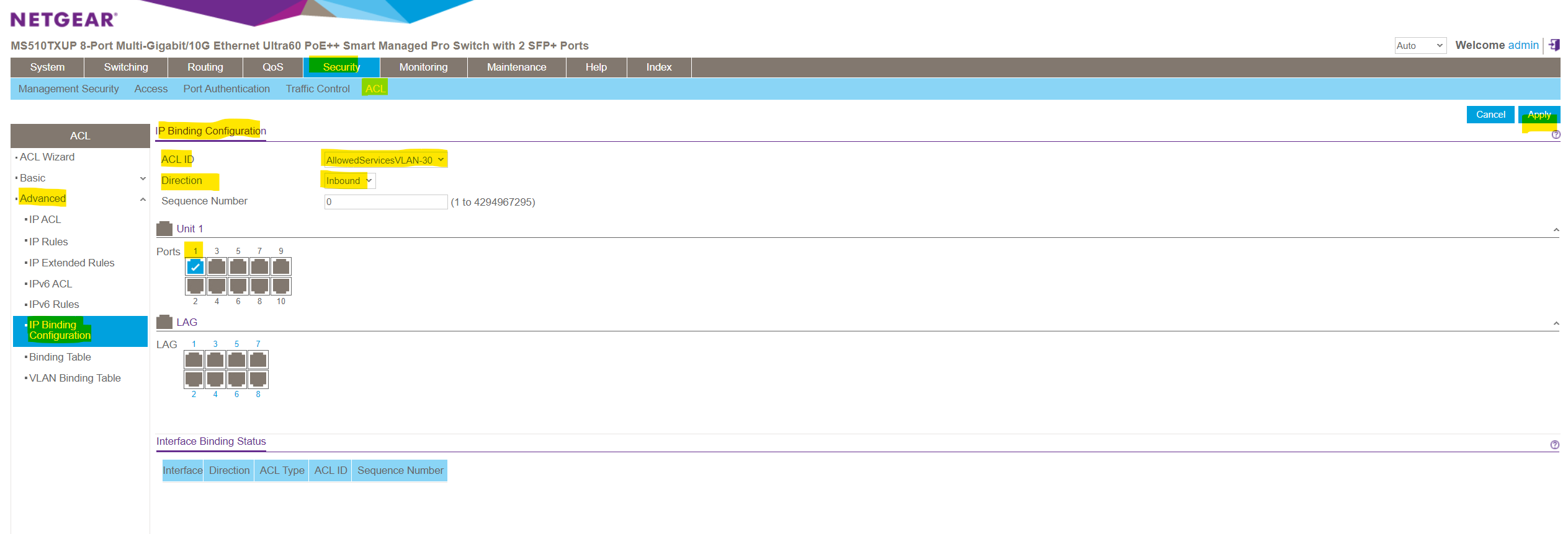
To just associate an ACL with a specific port on the switch, you can navigate to Security -> ACL -> Advanced -> IP Binding Configuration and first select the desired ACL and then associate separate ports by clicking on them as shown below. Finally click on Apply to enable the ACL just for these selected ports.
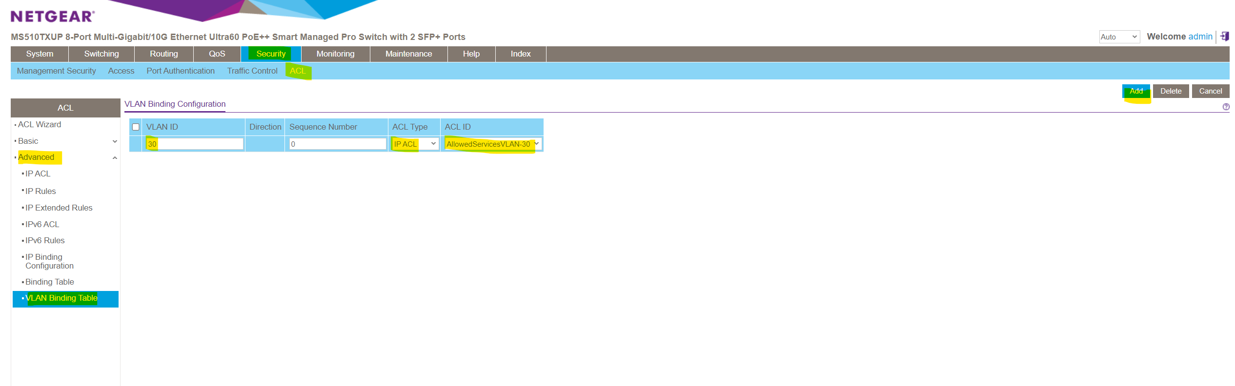
If you want these rules to be enabled and active on each ports which are member and associated to your affected VLAN, you can also associate the ACL directly to a VLAN as shown below. Therefore navigate to Security -> ACL -> Advanced -> VLAN Binding Table.
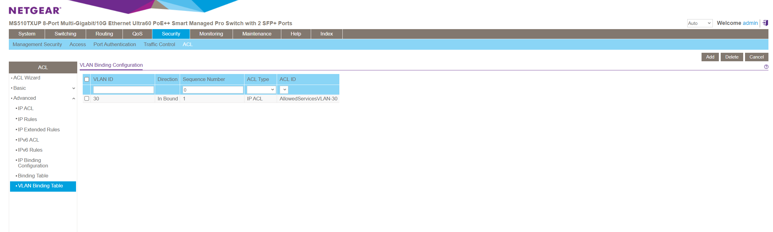
In the Sequence Number field, enter an optional sequence number.
You can specify an optional sequence number to indicate the order of this access list relative to other access lists that are already assigned to the VLAN ID and selected direction. A lower number indicates a higher precedence order. If a sequence number is already in use for the VLAN ID and selected direction, the specified access list replaces the currently attached ACL using that sequence number. If you do not specify a sequence number (the value is 0), a sequence number that is one greater than the highest sequence number currently in use for the VLAN ID and selected direction is used.The range is from 1 to 4294967295.
As you can see, by default the lowest available sequence number will be applied to in case you don’t explicitly enter one.
So from now on all devices which are connected to ports on this switch which are associated and member of VLAN 30, are just able to sent traffic which is permitted by the ACL into VLAN 30.
Because we didn’t further specify the ACEs (rules) regarding destination subnets, in gerneral just ICMP Echo Request and reply messages and HTTP/HTTPS traffic is allowed to send to the switch and all its VLANs it is a member of by devices connected to VLAN 30 we associated this ACL for.
Manage the NETGEAR MS510TXUP using the Lite CLI
Some NETGEAR Smart Switches now offer a command line interface (CLI) in addition to the local browser user interface (UI). The NETGEAR Smart Switch CLI does not support all of the configuration options that are available in the local browser UI, so we are calling it a lite CLI.
You can connect to your smart switch’s lite CLI using your preferred Secure Shell (SSH) client.
To access your smart switch’s lite CLI, you must meet the following requirements:
- Your switch model is listed under “This article applies to” on this knowledge article.
- You know the switch’s IP address and administrator password.
- Your switch is running a firmware version that supports the lite CLI
Source: https://kb.netgear.com/000064429/mDGAprccBFuwkbucoaaNIopZdHGsufWx?article=000064429
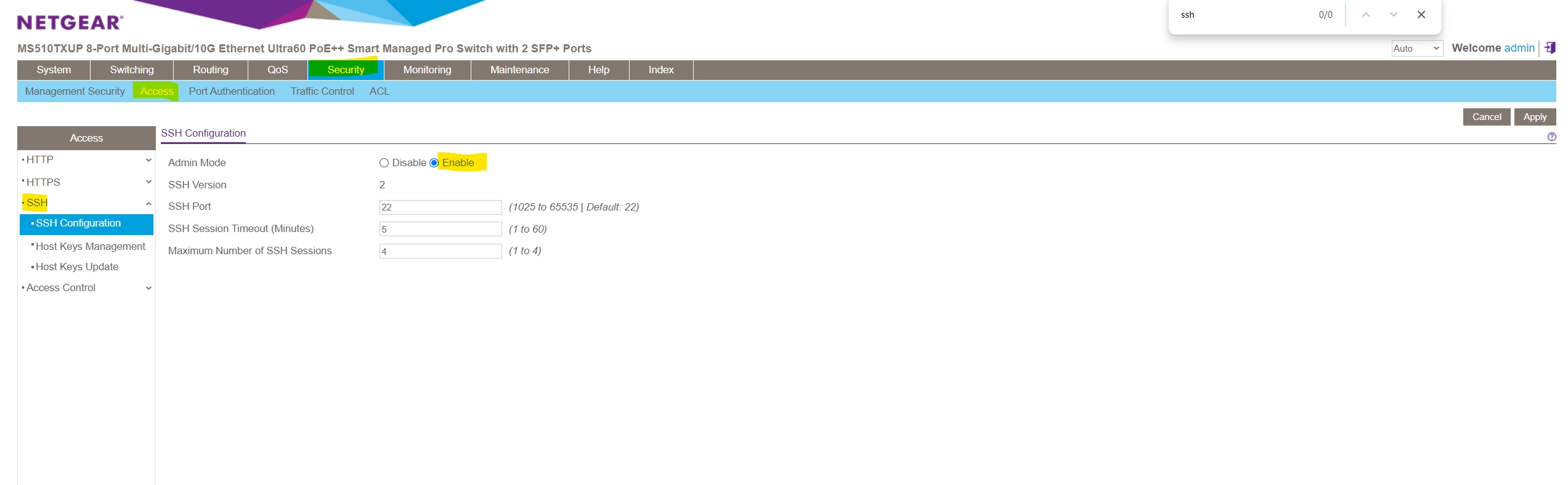
SSH access is enabled by default under Security -> Access -> SSH -> SSH Configuration. You can also adjust here the SSH Session Timeout.
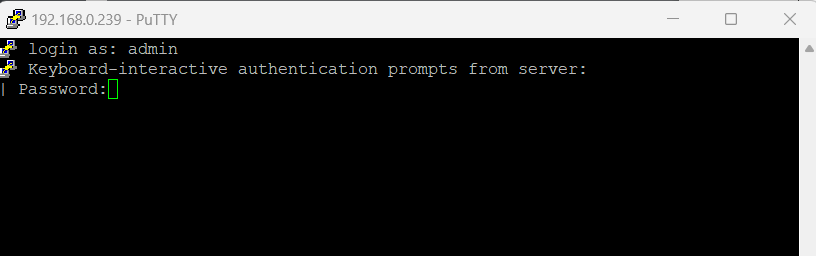
By using PuTTY enter the IP address of your switch and the default SSH Port 22. For the username I will use below the default admin user and the password I was set for.
Lite CLI Reference Manual
https://www.downloads.netgear.com/files/GDC/GS108Tv3/Smart_Switches_CLI_Manual_EN.pdf
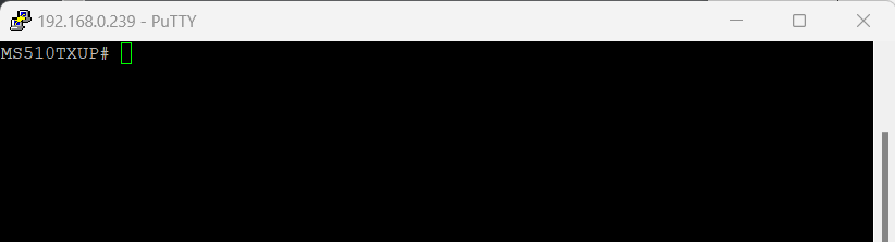
I will get logged on here directly into the privileged EXEC mode which is indicated by the # hashtag prompt as described in the table below.
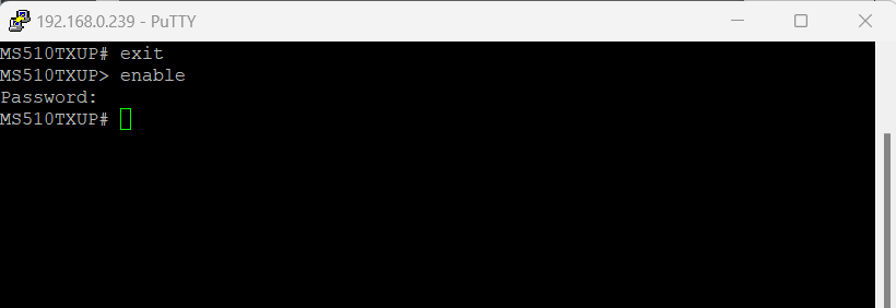
To leave the Privileged EXEC mode in switch to the User Exec mode just enter exit. To return to the Privileged EXEC mode, just enter enable and leave the password blank.
The following table describes how to enter or exit each mode.
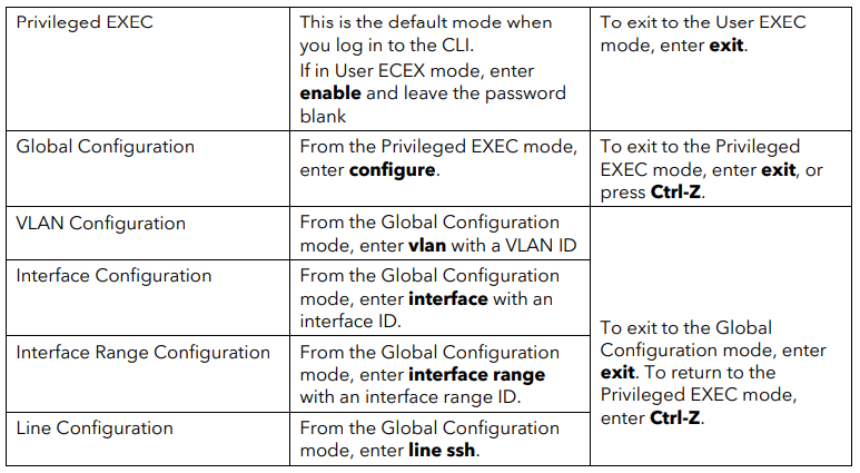
Source: https://www.downloads.netgear.com/files/GDC/GS108Tv3/Smart_Switches_CLI_Manual_EN.pdf
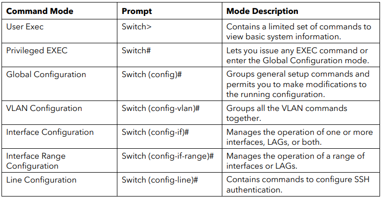
CLI Modes and Common Commands
The CLI groups commands into modes according to the command function. Each of the
command modes supports specific commands. The commands in one mode are not
available until you enter that specific mode. The only exception are the User EXEC mode
commands, which you execute in either the User EXEC mode or the Privileged EXEC mode.
The command prompt changes in each command mode to help you identify the current
mode. The following table describes the command modes and the prompts visible in that
mode.
Source: https://www.downloads.netgear.com/files/GDC/GS108Tv3/Smart_Switches_CLI_Manual_EN.pdf
All show commands can be issued from any configuration mode (Global Configuration,
Interface Configuration, VLAN Configuration, etc.). The show commands provide information
about system and feature-specific configuration, status, and statistics.
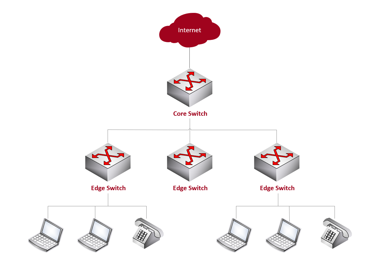
Core Switch vs. Edge Switch
An edge switch is a network switch that operates at the edge of a network. In networking terminology, the edge typically refers to the outermost boundary of a network where it connects to end-user devices or other networks.
Edge switches (aka access node or service node) play a crucial role in connecting devices such as computers, printers, servers, and other end-user devices to the local area network (LAN) or to other networks.
A core switch is a high-capacity network switch that typically operates at the core (backbone) or center of a computer network. It plays a crucial role in handling the major traffic within the network, connecting various segments of the network together. The core switch is a key component in the hierarchical network architecture commonly used in large enterprise networks.
Reset the switch to factory default settings but maintain the registration status
In case you have locked yourself out and can’t access the switch anymore, you can reset the switch by pressing the Reset button on the front panel for more than 5 seconds but less than 10 seconds. (Do not press the button for more than 10 seconds!)
When pressing the Reset button on the front panel for more than 10 seconds you will reset the switch to factory default settings and reset the registration status.
This option can be useful if you want to register the switch under a different name or account. This option requires you to first contact NETGEAR support at https://netgear.com/support so that the NETGEAR registration status on the NETGEAR server can be reset. Then, you can use this option to erase all settings, reset the switch to factory defaults, go through the initial log-in process again, and reregister the switch with NETGEAR.
VXLAN (Virtual Extensible LAN)
VXLAN (Virtual Extensible LAN) is a modern network encapsulation technology designed to overcome the limitations of traditional VLANs. A classic VLAN provides layer-2 segmentation within a broadcast domain but is limited to 4,096 VLAN IDs, making large-scale multi-tenant or cloud environments difficult to design. VXLAN solves this by introducing a 24-bit VXLAN Network Identifier (VNI), which supports over 16 million isolated layer-2 segments, far beyond the capabilities of standard VLANs.
Unlike VLANs, which operate natively at L2 and typically require physical or logical adjacency, VXLAN encapsulates Ethernet frames inside UDP packets, allowing L2 networks to be extended across L3 routed infrastructures.
This makes VXLAN ideal for distributed datacenters, cloud architectures, and multi-tenant environments where you need to stretch broadcast domains across geographic distances or IP-based underlays.
The result is that VXLAN provides the familiar operational model of VLANs, but with much greater scalability, portability, and flexibility, enabling virtualized workloads to move without depending on physical network boundaries.
In short: VLANs segment a single LAN, while VXLAN allows those LAN segments to elastically span routed networks at datacenter or cloud scale.
Links
How to configure a VLAN on a NETGEAR managed switch
https://kb.netgear.com/31026/How-to-configure-a-VLAN-on-a-NETGEAR-managed-switchWhat are Link Aggregation Groups (LAGs) and how do they work with my managed switch?
https://kb.netgear.com/21632/What-are-Link-Aggregation-Groups-LAGs-and-how-do-they-work-with-my-managed-switchWhat are Access Control Lists (ACLs) and how do they work with my managed switch?
https://kb.netgear.com/21708/What-are-Access-Control-Lists-ACLs-and-how-do-they-work-with-my-managed-switch
Tags In
Related Posts
Latest posts
How Multicast Traffic Works in VMware vSphere – Testing VSS (Basic Multicast Filtering) vs VDS (IGMP/MLD Snooping) with Video Streaming – Part 2
Follow me on LinkedIn