Mastering GCP Virtual Machines – Part 8 (Networking Best Practices)
Google Cloud Platform (GCP) provides a powerful and flexible networking foundation that can scale from simple projects to complex, global architectures.
But with that flexibility comes complexity: designing networks that are secure, cost-efficient, and easy to manage requires careful planning.
In this post, we will explore basic key best practices for building and operating networks in GCP, covering topics such as VPC design, subnetting, firewall rules, connectivity options, and operational governance, so you can avoid common pitfalls and create an environment that is both resilient and future-proof.
You can also read my following posts about different options to provide outbound internet access and especially by using an NGFW appliance placed into the Hub VPC in a Hub-and-spoke NCC design.
And about building a Centralized Egress and Hybrid Connectivity Hub by using the Network Connectivity Center (NCC).
Determine if Firewall is active on Linux
When configuring VPC peerings and VPC firewalls for testing and analyzing traffic flow, we also need to be sure that in the end not the local firewall from our VM instances will block the traffic.
The Network Intelligence – Connectivity Tests for example evaluate reachability across the Google Cloud data plane (VPC routing, firewall rules, peering, Cloud NAT, VPN, load balancers, etc.), it will not inspect inside the guest OS.
GCP firewall rules (the VPC-level, project-level rules) are checked while local firewalls inside a VM (like iptables, nftables, firewalld, Windows Defender Firewall) are not checked.
About how to check if the Linux firewall is active across different Linux distribution, you can read my following post.
Virtual Private Cloud (VPC) Design
A common best practice in larger GCP environments is to use a hub-and-spoke network design. In this model, you create a central “hub” VPC that hosts shared services such as:
- Cloud NAT or proxy servers for internet egress.
- Firewalls, IDS/IPS, or security appliances for traffic inspection.
- VPN or Interconnect gateways for hybrid connectivity.
- Central DNS resolvers or Private Service Connect endpoints.
Other workloads are placed in spoke VPCs. Each spoke is typically tied to a specific environment (e.g., dev, test, prod) or business unit, and connects back to the hub through VPC peering or transit routing via a Shared VPC.
This approach provides several benefits:
- Centralized security – inspection and monitoring happen in one place.
- Separation of concerns – teams can manage their own spoke VPCs without affecting core connectivity.
- Scalability – easier to add new environments or projects by attaching new spokes.
- Cost awareness – routing and egress can be controlled centrally to avoid surprises.
In short, hub-and-spoke helps you balance isolation and governance while still enabling efficient connectivity across projects and environments.
In scenarios where no dedicated firewall or inspection appliance is deployed, a single Hub VPC is fully sufficient. It can host components like Cloud Router and HA VPN to handle route exchange and site connectivity, while native VPC firewall rules manage access control.
However, once traffic inspection or filtering is required, it’s best practice to split the hub into trusted and untrusted VPCs to clearly separate internal and external traffic paths. You will see this design in my following post https://blog.matrixpost.net/cross-hub-connectivity-in-google-cloud-using-ha-vpn-and-ngfw-appliances/.
In this post I will show how to use a hub-and-spoke VPC design.
More about the Hub-and-spoke network architecture in Google Cloud you will also find here https://cloud.google.com/architecture/deploy-hub-spoke-vpc-network-topology.
Set up a Hub-and-spoke Network Architecture
An enterprise can separate workloads into individual VPC networks for the purposes of billing, environment isolation, and other considerations.
However, the enterprise might also need to share specific resources across these networks, such as a shared service or a connection to on-premises.
In such cases, it can be useful to place the shared resource in a hub network (referred to as the routing network) and to attach the other VPC networks as spoke networks (referred to as workload networks).
The following diagram shows a hub-and-spoke network with two workload VPCs, though more workload VPCs can be added.
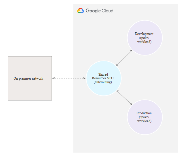
Source: https://cloud.google.com/architecture/deploy-hub-spoke-vpc-network-topology
In this example, separate workload VPC networks are used for the workloads of individual business units within a large enterprise.
Each workload VPC network is connected to a central routing VPC network that contains shared services and can serve as the sole entry point to the cloud from the enterprise’s on-premises network.
We can implement a Hub-and-spoke Network Architecture by using either the Network Connectivity Center, VPC Network Peering or Cloud VPN.
Below I will show all three options.
By using the Network Connectivity Center
Network Connectivity Center is an orchestration framework that simplifies network connectivity among spoke resources that are connected to a central management resource called a hub.
When a hub uses VPC spokes, you can configure connectivity between these VPC networks connected to the hub by exchanging subnet routes between all or some of the VPC networks.
A Network Connectivity Center hub is a global resource to which you attach spokes. A single hub can contain spokes from multiple regions.
A spoke represents one or more Google Cloud network resources that are connected to a hub.
More about you will find here https://cloud.google.com/network-connectivity/docs/network-connectivity-center/concepts/overview.
!! Note !!
Network Connectivity Center (NCC) Hub is the central, global management resource in GCP. It doesn’t carry traffic itself; it holds the routing policy (the “rulebook”) and coordinates connections.Hub VPC is the actual VPC Network that acts as your central services or transit network.
For VPC-to-VPC connectivity via NCC, every single VPC network that needs to communicate (the “Hub VPC” and all “Spoke VPCs”) must be added to the NCC Hub resource as a VPC Spoke.
So also our Hub-VPC need to be added as VPC Spoke in the NCC for cross-VPC routing.
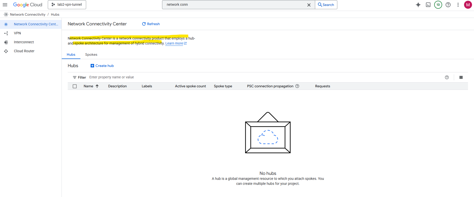
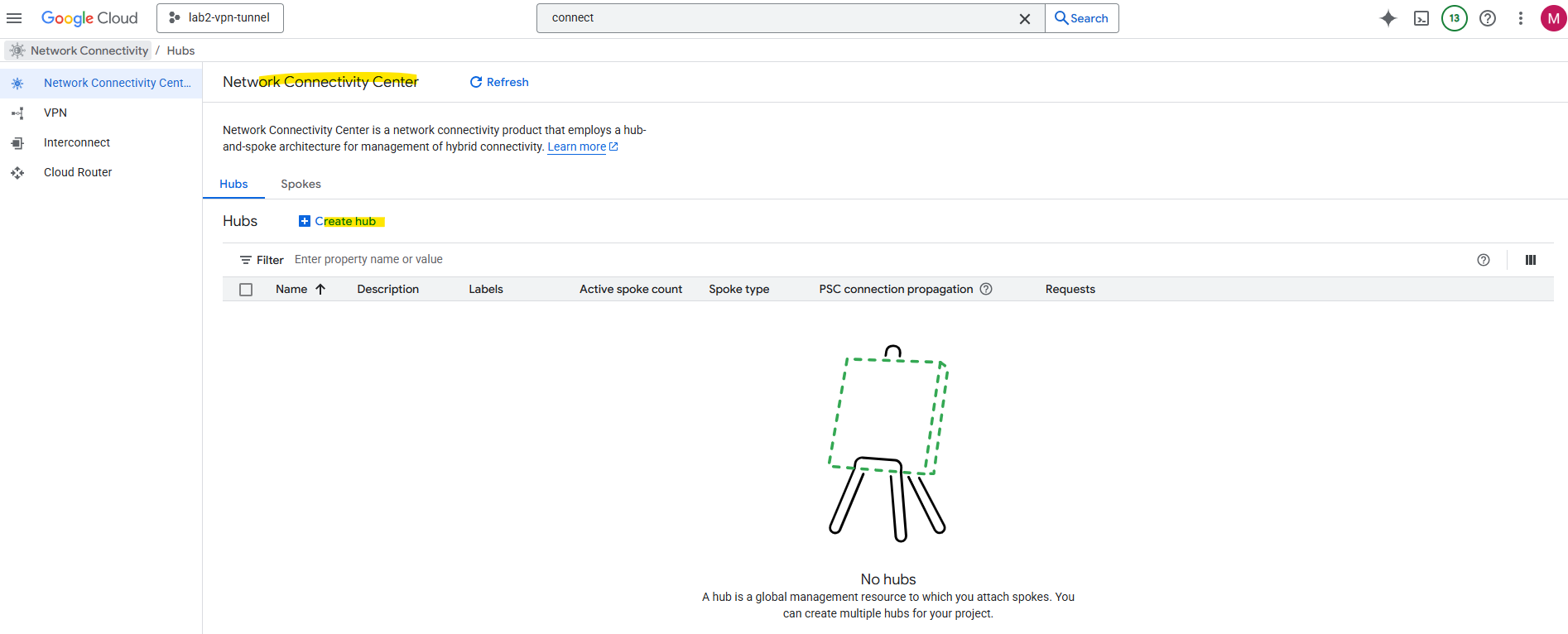
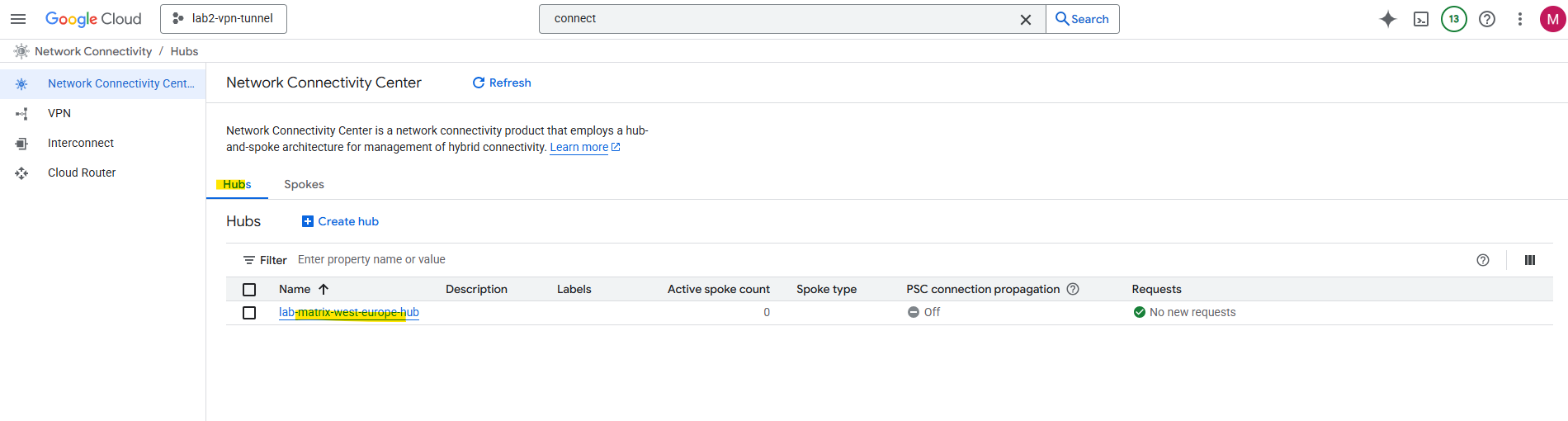
Create a Hub
In the Network Connectivity Center on the Hubs tab click on Create Hub.
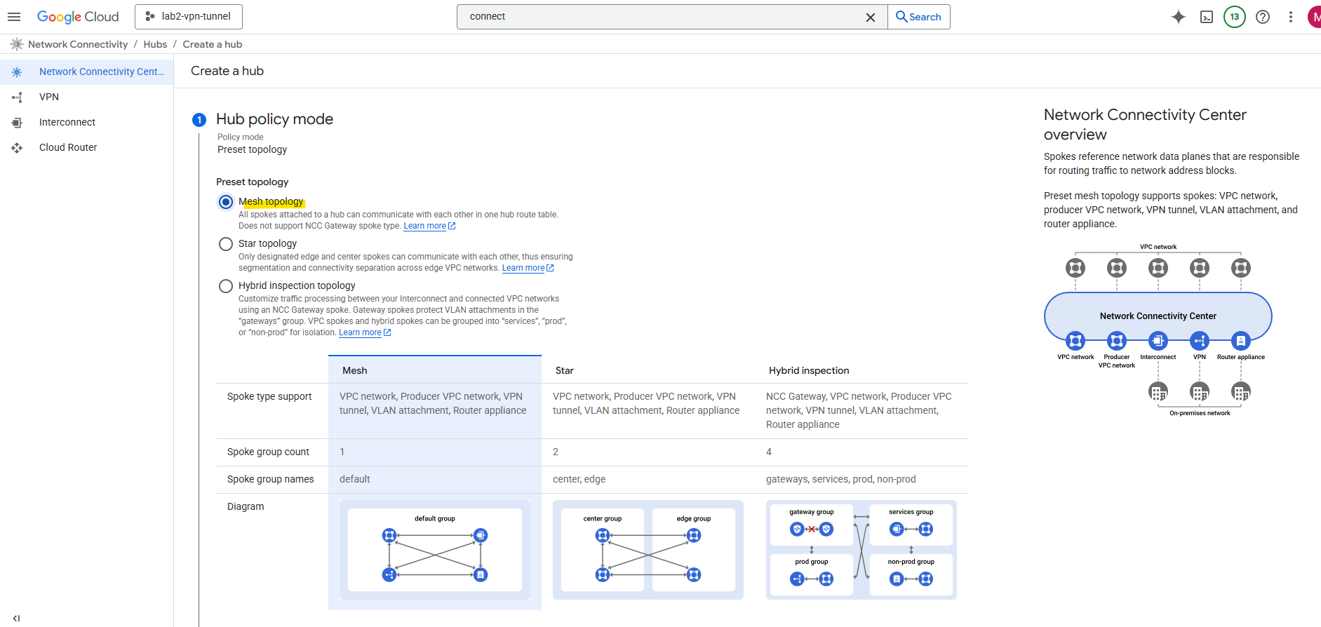
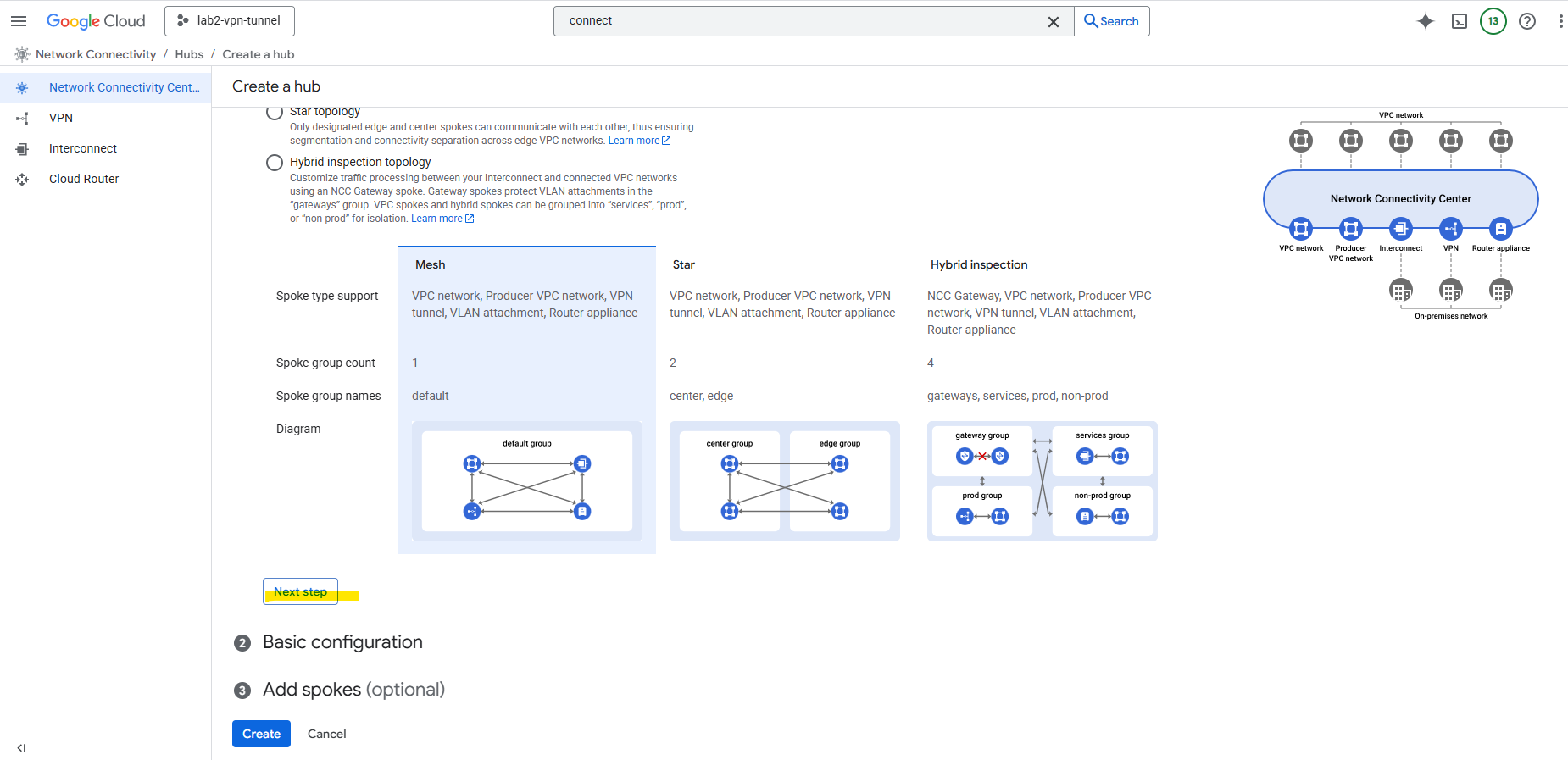
I will use the Mesh topology. All spokes attached to a hub can communicate with each other in one hub route table.
Every VPC connects directly to every other VPC (many-to-many). This gives full flexibility but quickly becomes complex and hard to manage as the number of networks grows.
Using a star topology prevents inter-VPC-spoke (workload VPC) communication while the mesh topology does not.
The Hybrid Inspection Topology mandates that all cloud-to-cloud and hybrid traffic must be steered through a centralized set of Next-Generation Firewalls (NGFWs) in the Hub VPC for deep, stateful inspection.
In contrast, a Mesh Topology is optimized for direct, low-latency communication between networks, allowing traffic to bypass any central inspection point. The Mesh relies on simpler, decentralized native cloud firewall rules, sacrificing deep inspection for speed and direct routing efficiency.
Details about each topology available you will find here https://cloud.google.com/network-connectivity/docs/network-connectivity-center/concepts/connectivity-topologies.
Click on Next Step.
Enter a name for the Hub and select if Private Service Connect connection propagation is enabled.
Private Service Connect connection propagation allows services in VPC spokes to be transitively and globally accessible from other VPC spokes in the same hub.
https://cloud.google.com/vpc/docs/about-propagated-connections
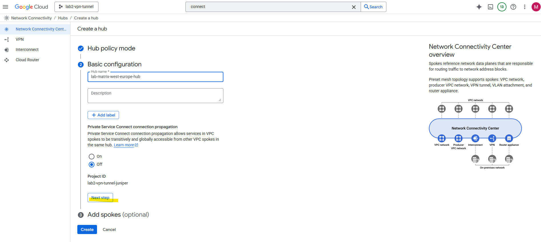
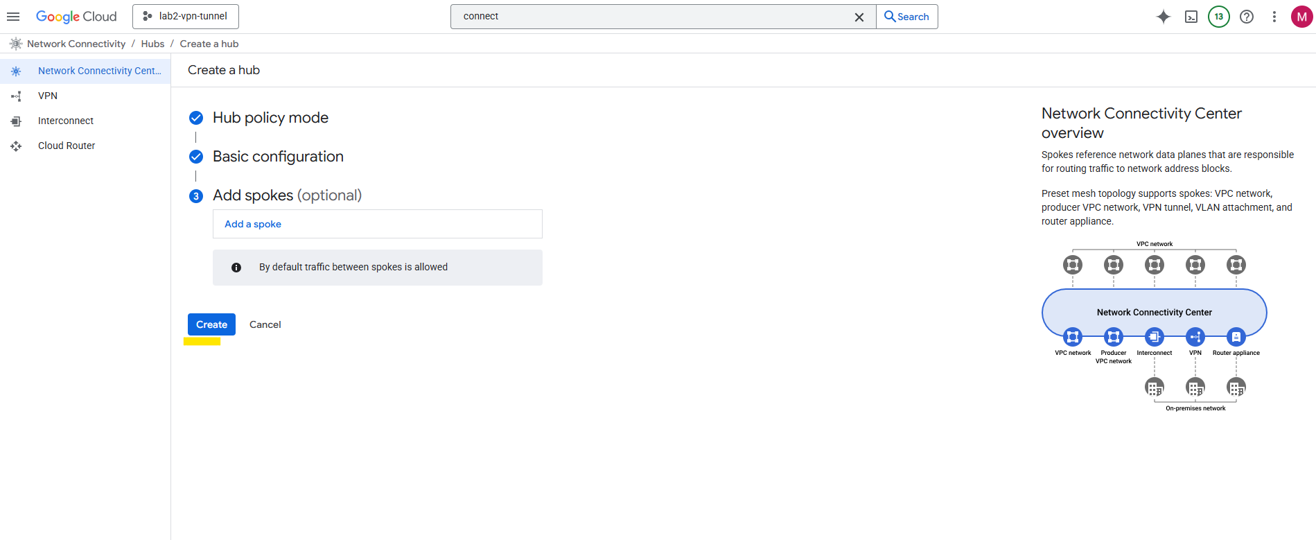
Click on Create. We can also add a spoke already to our new hub, I will add a spoke in the next section below.
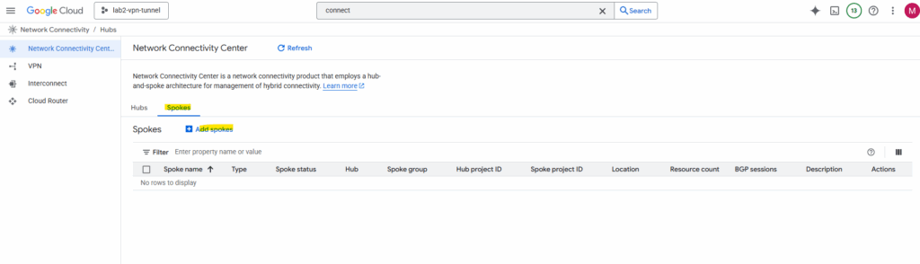
Add a Spoke
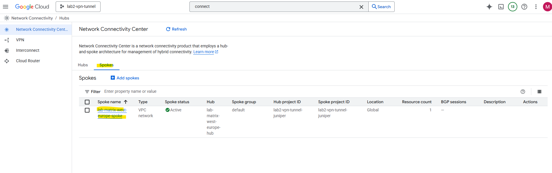
In the Network Connectivity Center on the Spokes tab click on Add spokes.
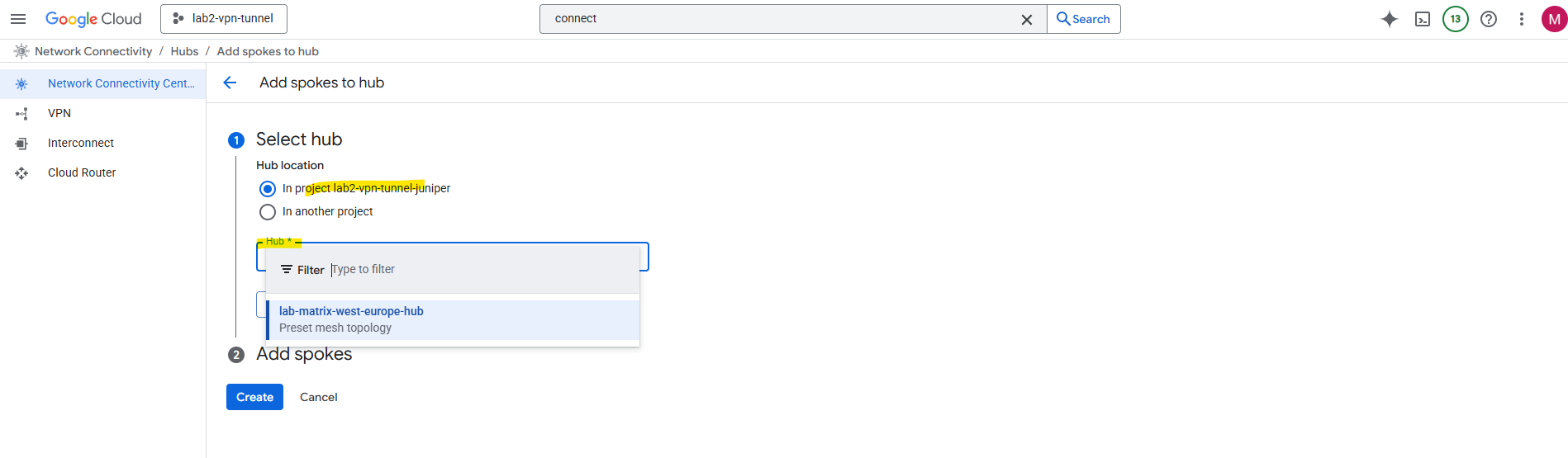
Select our previously created hub and click on Next.
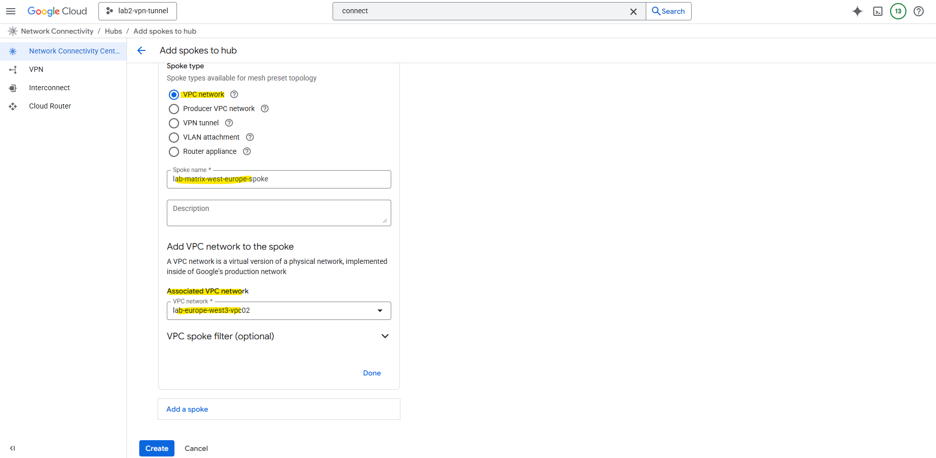
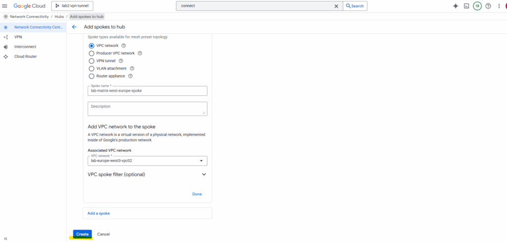
For the spoke type I will use VPC network. Enter a name and select which existing VPC network you want to add as spoke. I will add here the VPC network named lab-europe-west3-vpc02 which I will use for spoke workloads.
VPC spokes let you connect two or more VPC networks to a hub so that the networks exchange subnet routes.
How to use the spoke type with Router appliance we will see in in Part 9.
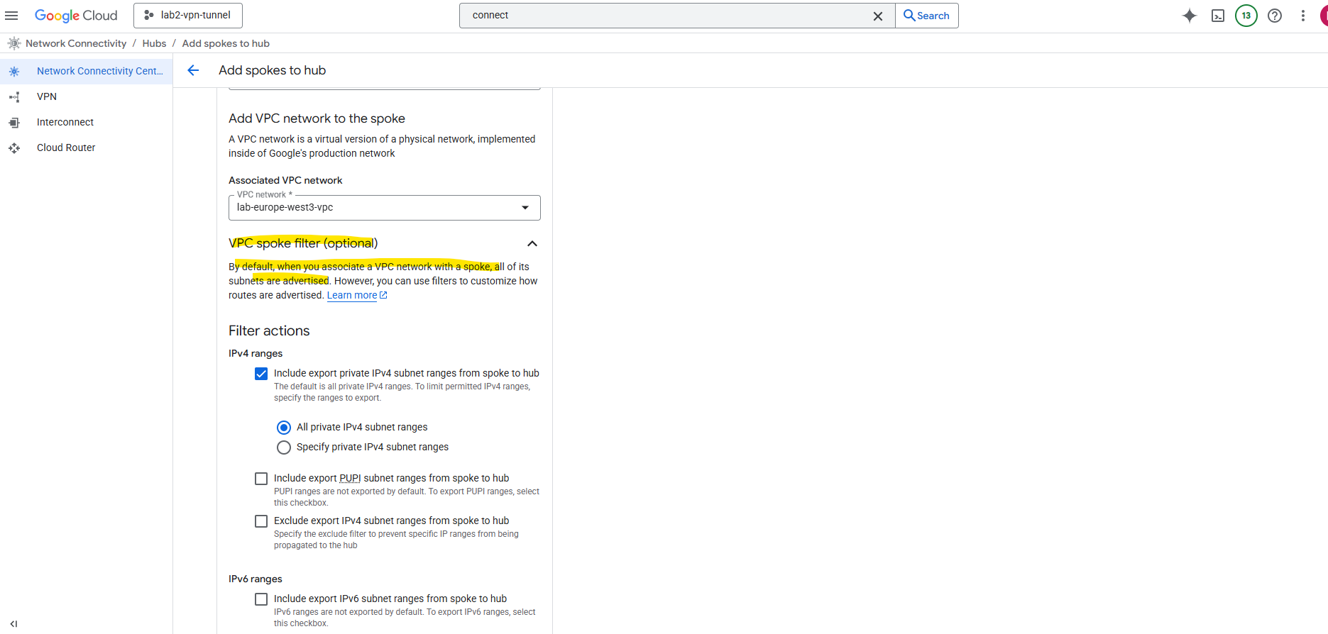
We can also filter which subnets should be advertised.
By default, when you associate a VPC network with a spoke, all of its subnets are advertised. However, you can use filters to customize how routes are advertised
Click on Create.
The same steps we will also perform to add our existing Hub-VPC as new NCC spoke (spoke type: also VPC networK) for cross-VPC routing.
Make the HA VPN Available in the Hub
By default, when you drop an HA VPN into one VPC, it’s only available to that VPC. If you want it to be usable across all your NCC spokes, you need to advertise and share that hybrid route through the NCC hub.
The hub is where we will connect both our HA VPN and our spoke VPCs.
To make our HA VPN available in the hub, we need do add our HA VPN as spoke to our hub.
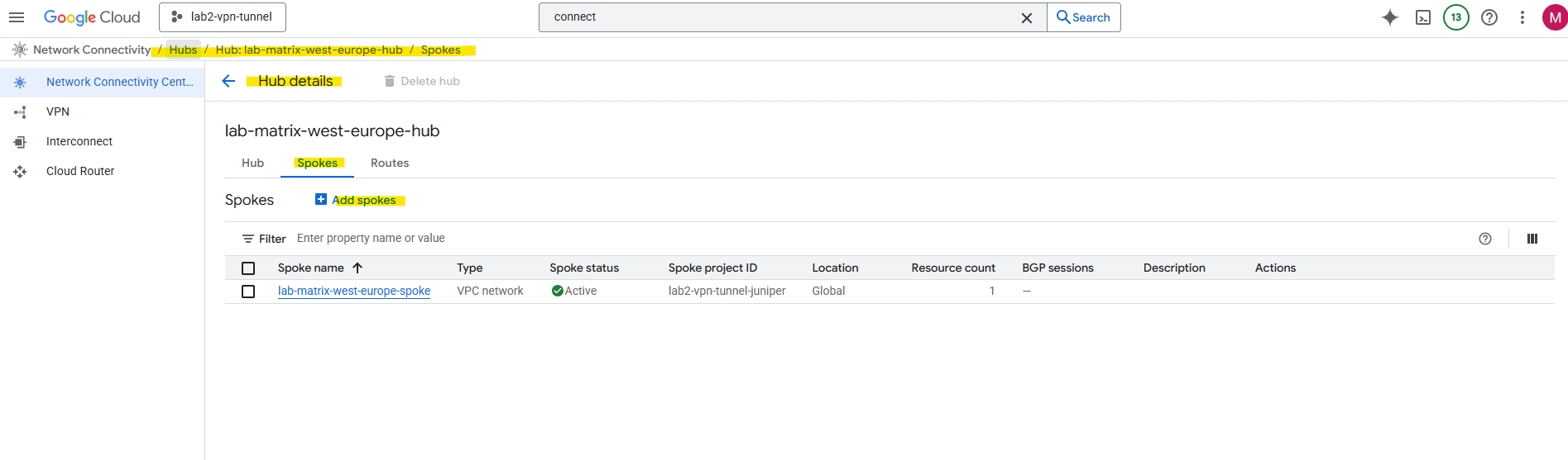
In the hub details page, click Add Spoke.
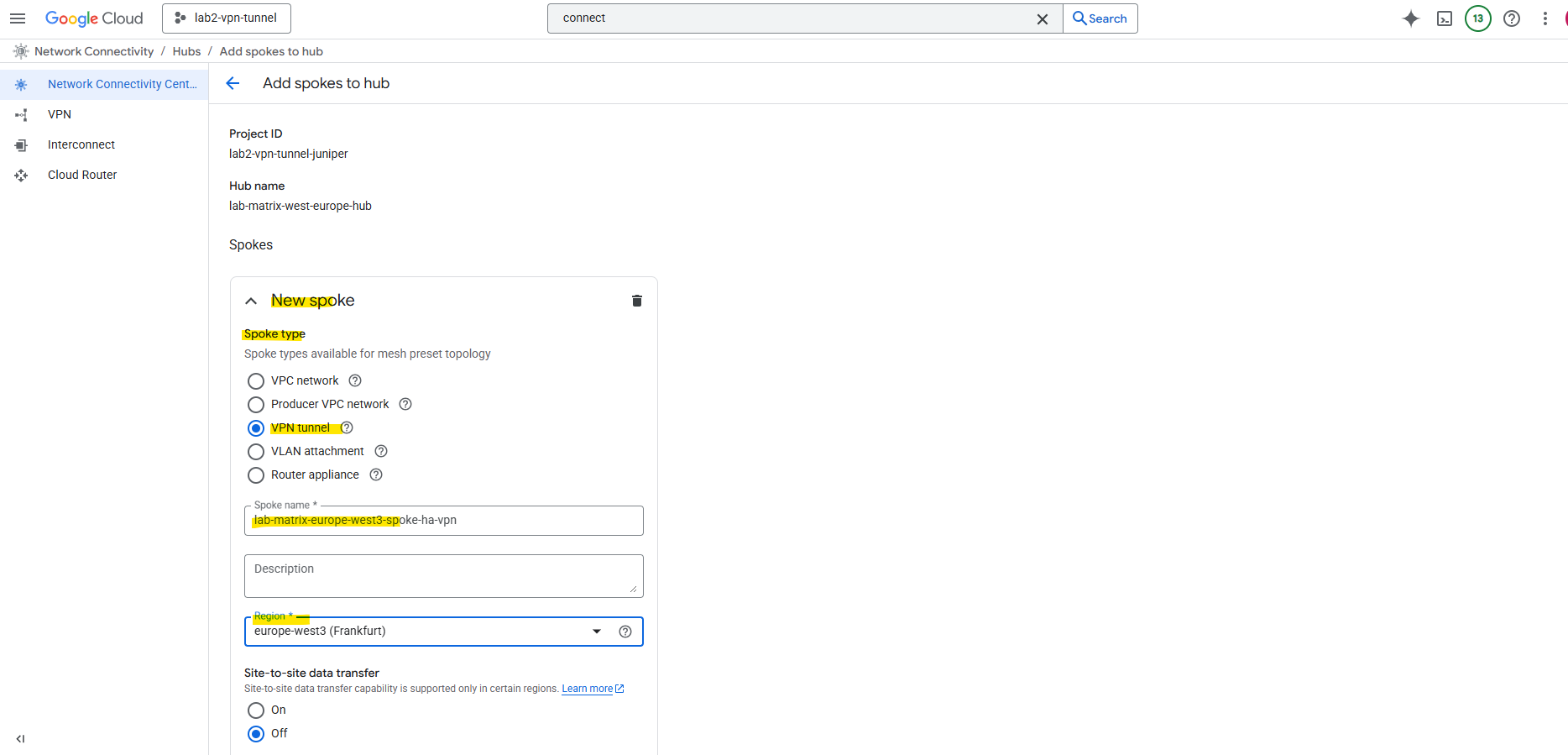
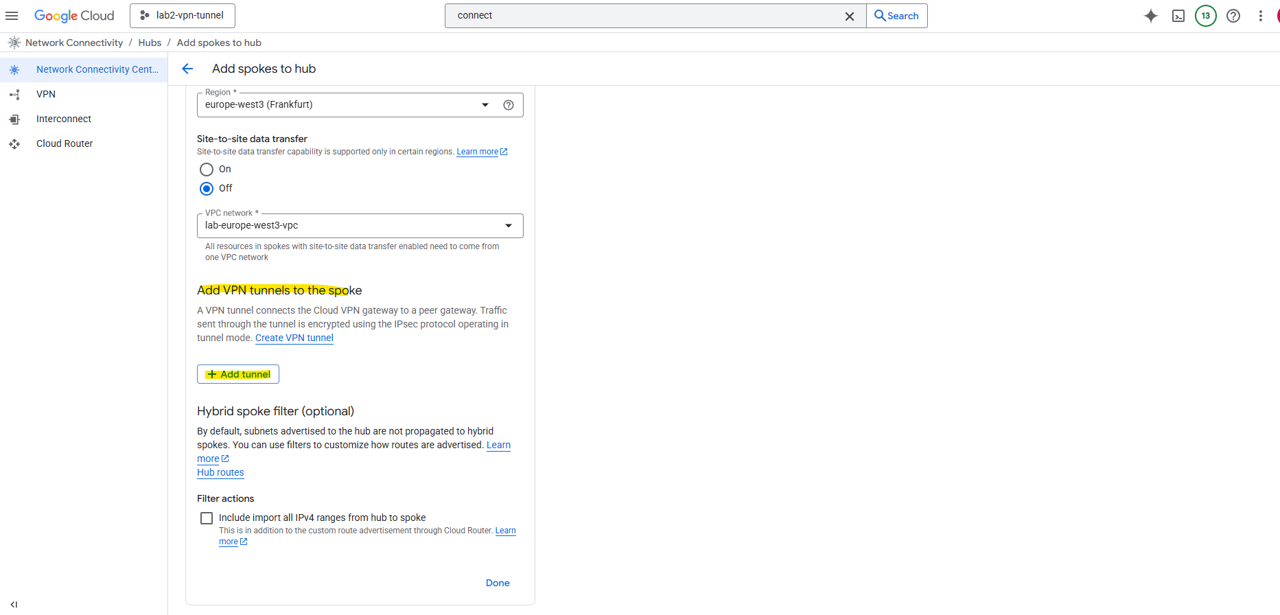
For the spoke type select VPN tunnel. Further enter a name for the new spoke, the region and VPC network our HA VPN tunnel resides.
A VPN tunnel spoke lets you add HA VPN tunnels to a hub to establish site-to-cloud connectivity between your external sites and your VPC networks or site-to-site data transfer between your external sites.
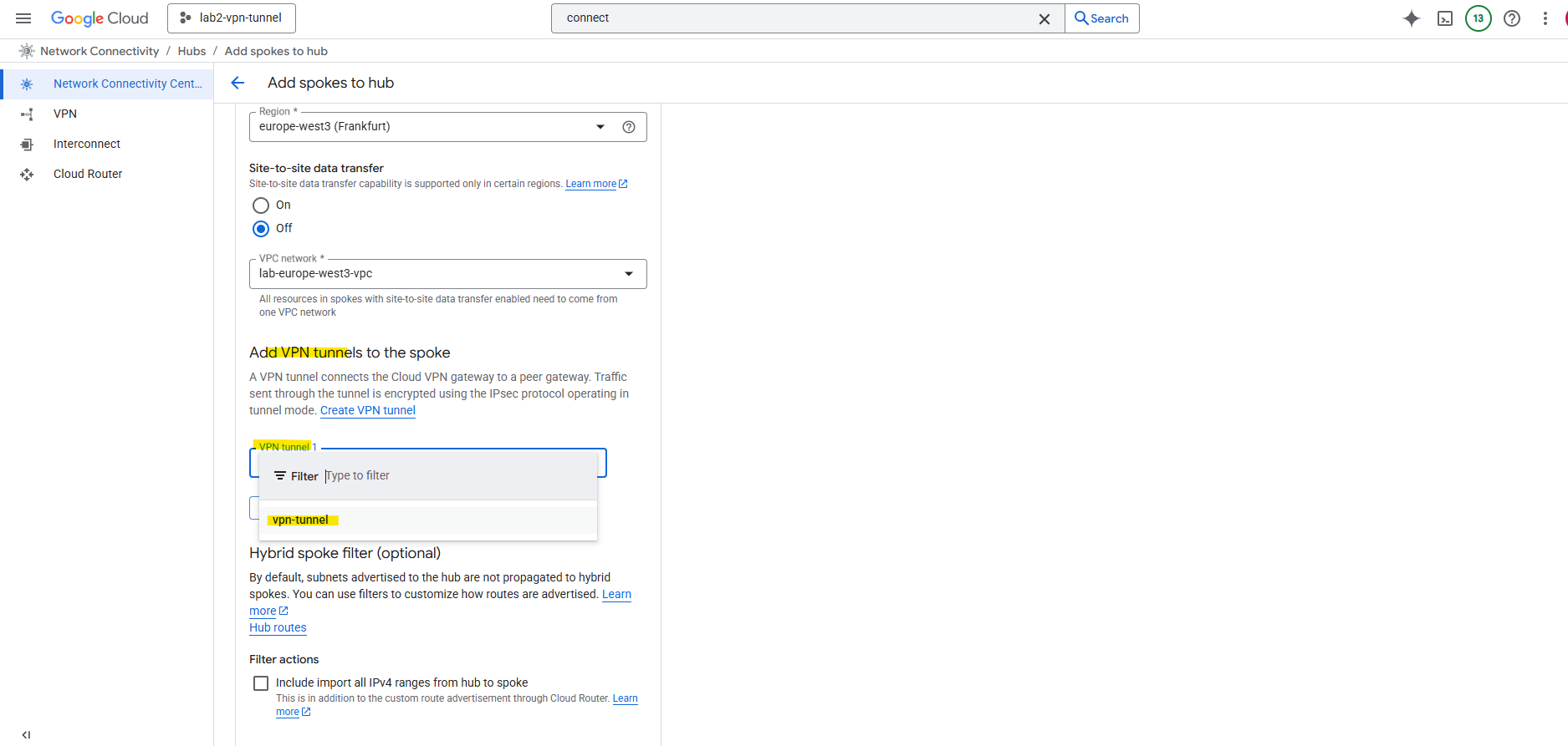
Click on Add tunnel.
A VPN tunnel connects the Cloud VPN gateway to a peer gateway. Traffic sent through the tunnel is encrypted using the IPsec protocol operating in tunnel mode.
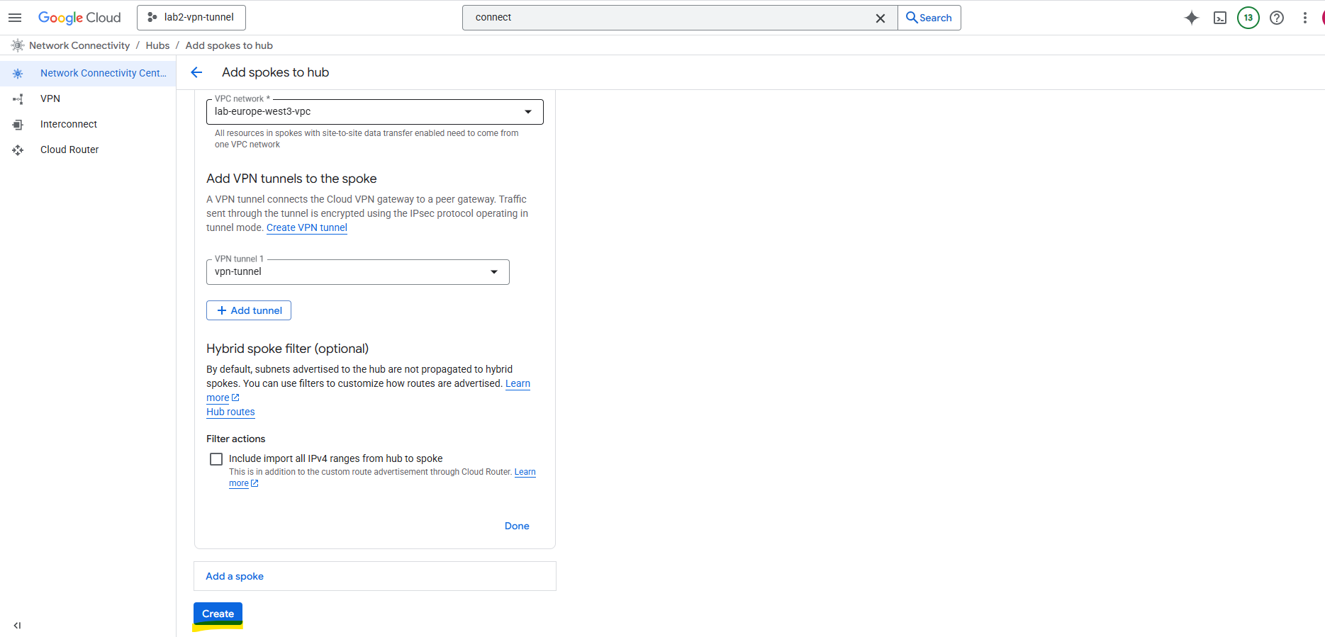
I will select my existing tunnel named vpn-tunnel (which connects my on-prem lab vSphere environment with GCP).
About how to setup HA VPN to connect your on-prem network you will find in my following post.
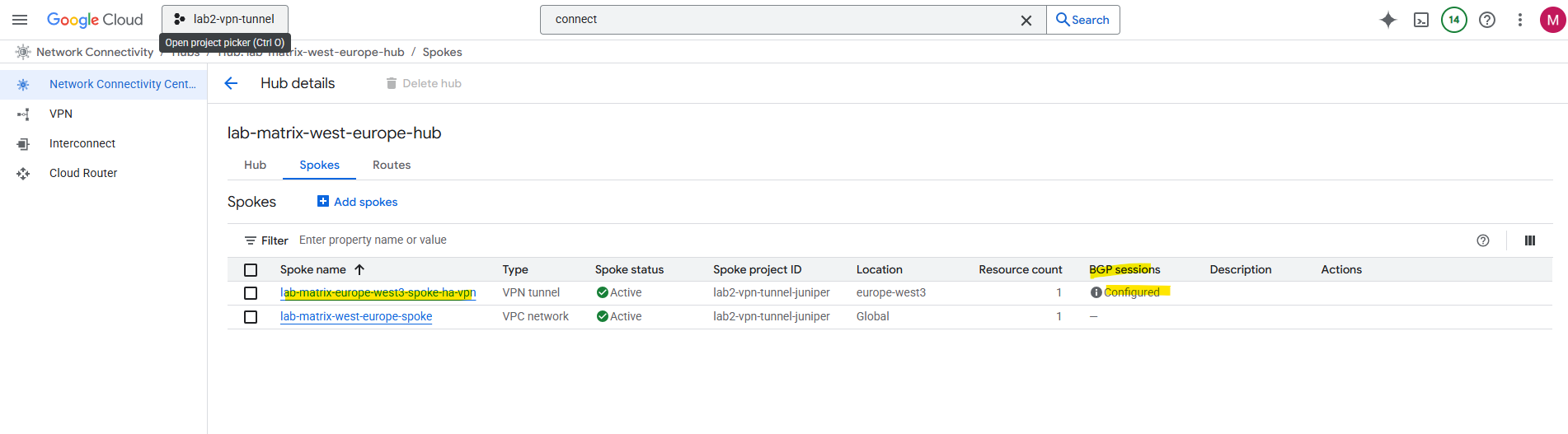
Click on Create. This registers our HA VPN as a spoke so its routes can flow into the hub.
Below I can already see that BGP sessions already configured for the vpn tunnel.
On the hub details page in the route tabs we can see the advertised routes, select the region for which you want to view routes.
Below I can already see all of my 3 on-prem subnets connected through the vpn tunnel.
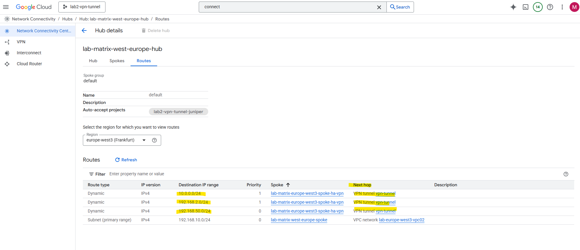
So far the route for my dedicated GCP spoke VPC network (subnet) will not be advertised to my on-prem VPN device (pfSense).
The highlighted 172.17.0.0/24 subnet is from the VPC network including my HA VPN and I was adding as new spoke with the spoke type ==> VPN tunnel.
By default, when you hook up your spoke VPCs to a Network Connectivity Center hub that already has an HA VPN, the on-prem side only sees the hub’s routes. The spoke VPC prefixes won’t automatically be advertised back to on-prem unless you explicitly configure that in Cloud Router.
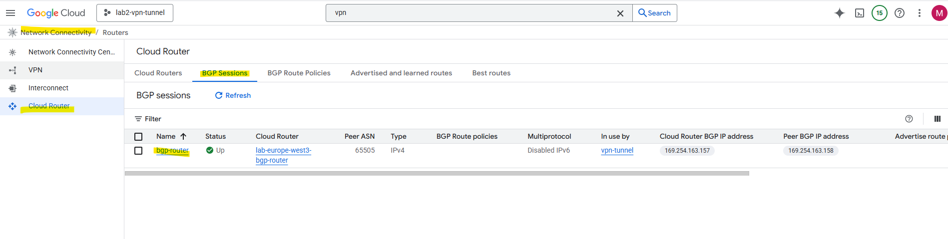
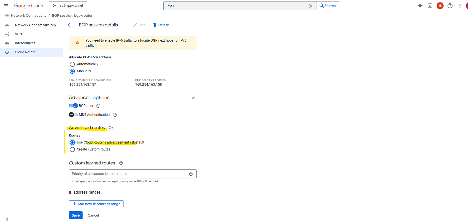
Navigate to the Cloud Router -> BGP Session tab within the Network Connectivity Center. Click on the BGP session.
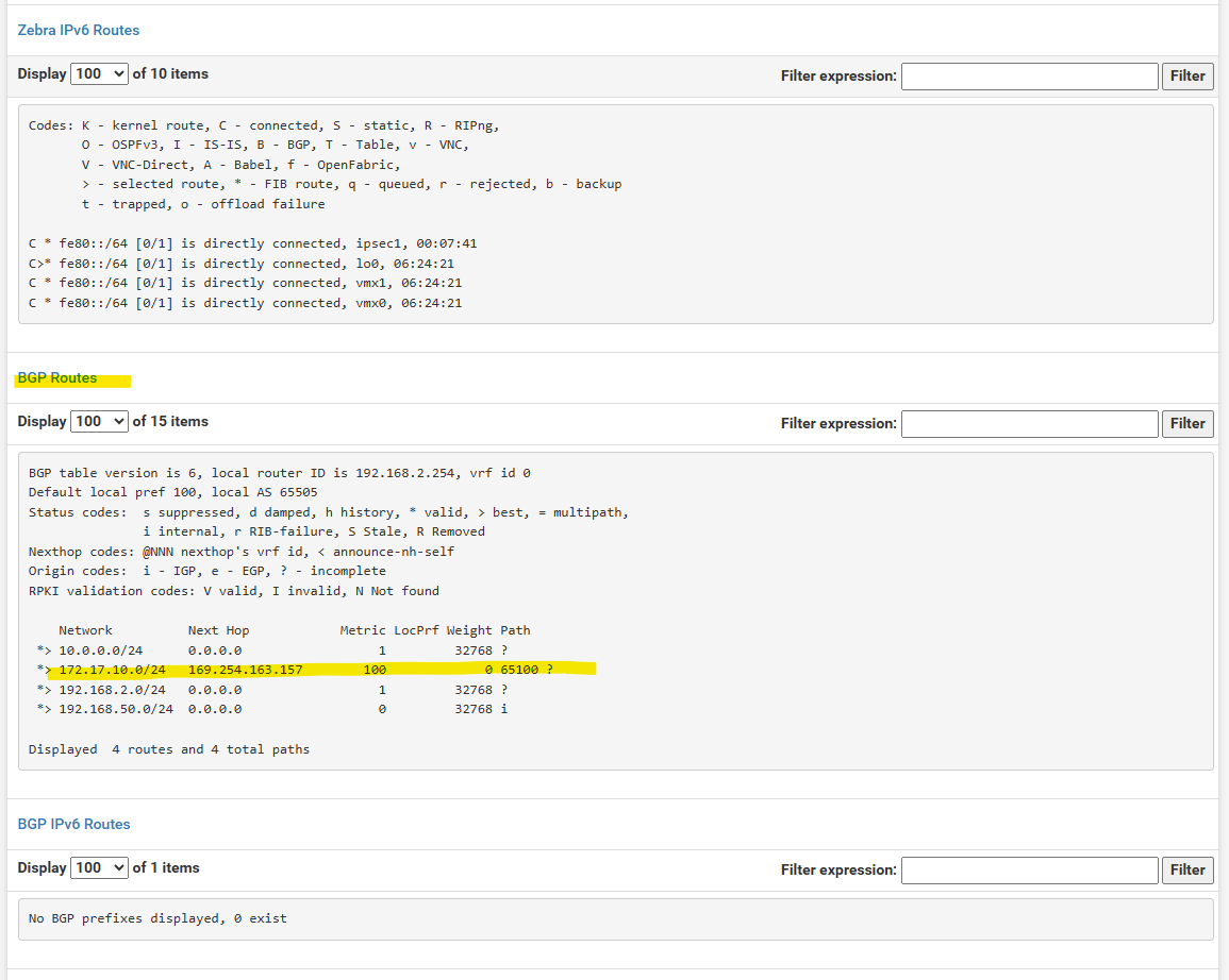
Below we can already see, that so far just the 172.17.10.0/24 subnet is advertised to on-prem.
Click on Edit.
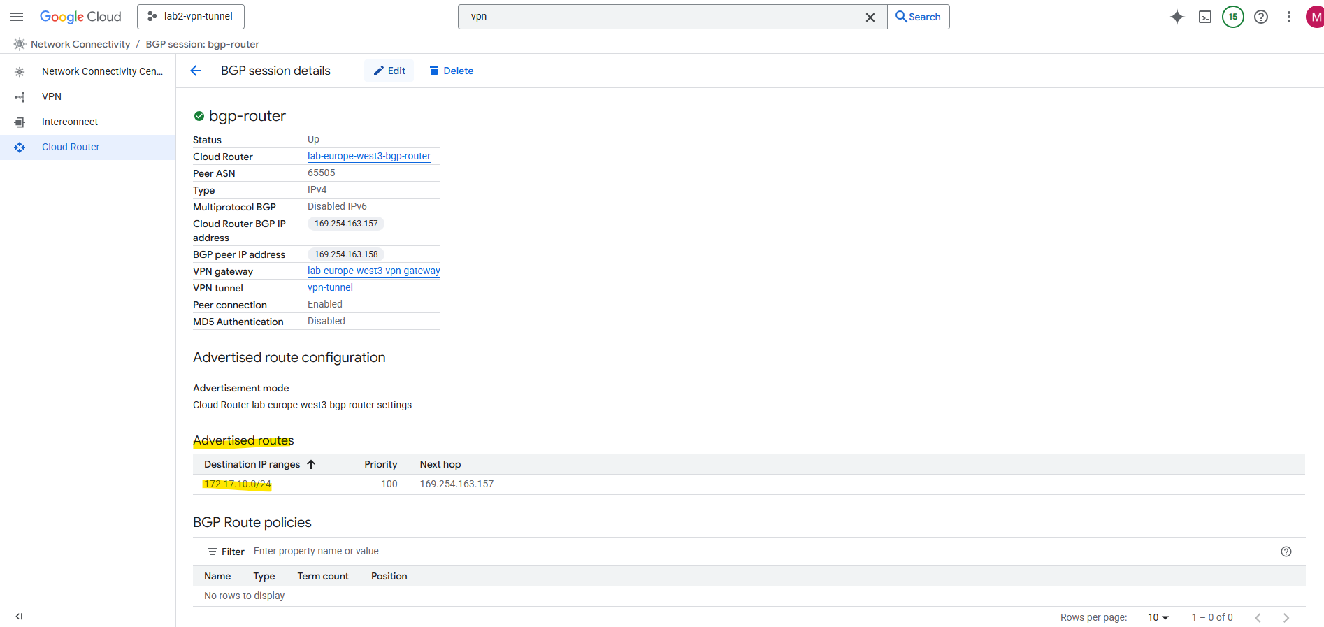
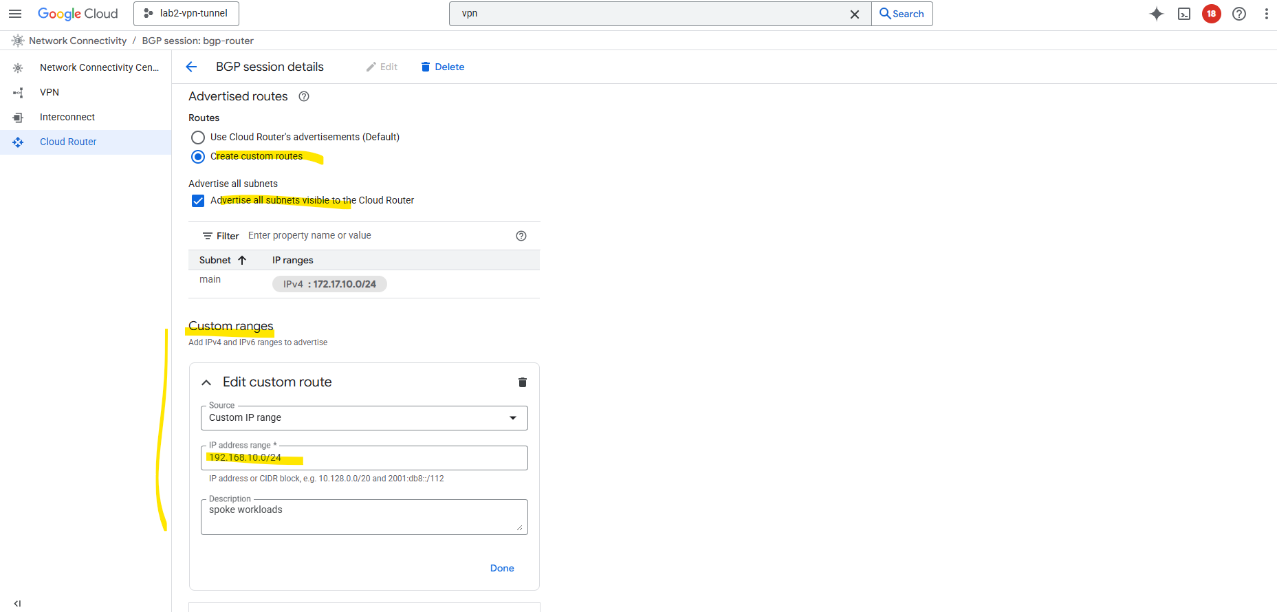
By default, it only advertises subnets from its own VPC. To include spoke routes, select Create custom routes below.
I will check Advertise all subnets visible to the Cloud Router and adding my workload subnet 192.168.10.0/24 which is associated with the spoke.
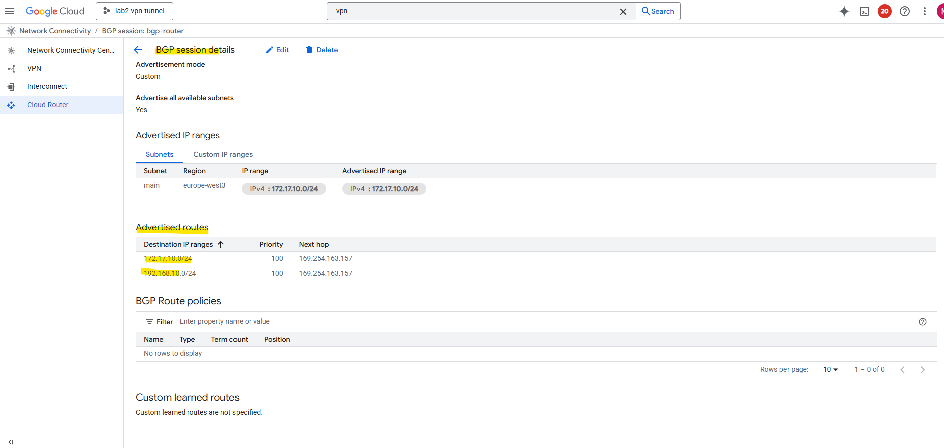
Now both subnets should be advertised to my on-prem VPN device.
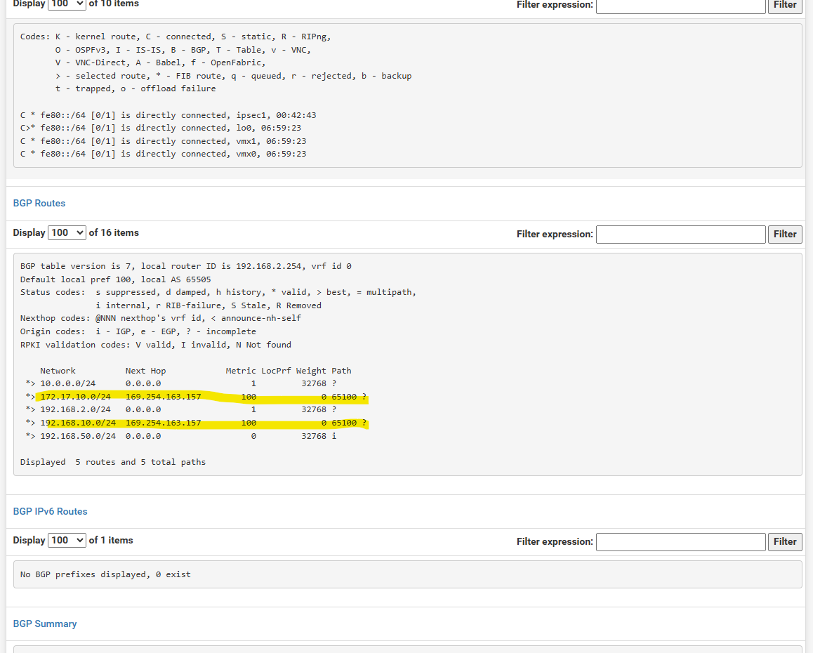
Looks good on pfSense.
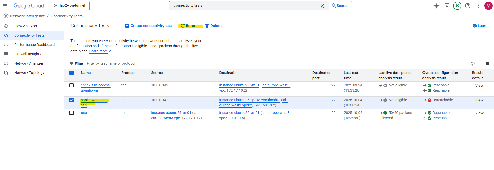
Nevertheless, so far I am not able to connect from on-prem to a VM instance (workload) running in the spoke VPC network.
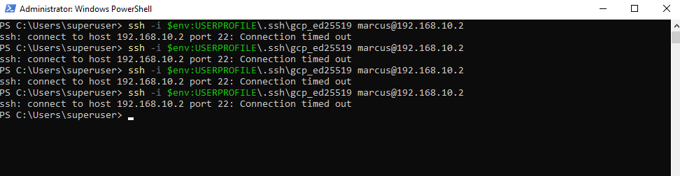
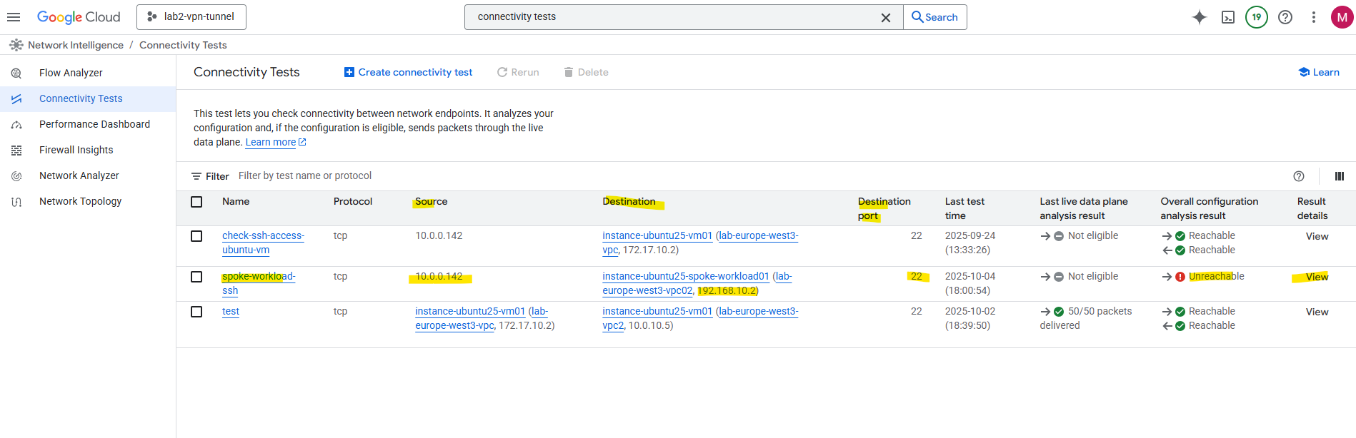
I already know that so far I am not allowing on the destination VPC network (spoke) inbound TCP 22 (SSH) traffic, just to demonstrate that we can use the Network Intelligence – Connectivity Tests tool, to analyze where exactly traffic is blocked.
So I will first need to allow inbound TCP 22 (SSH) traffic on the VPC network (spoke) the VM instance is running.
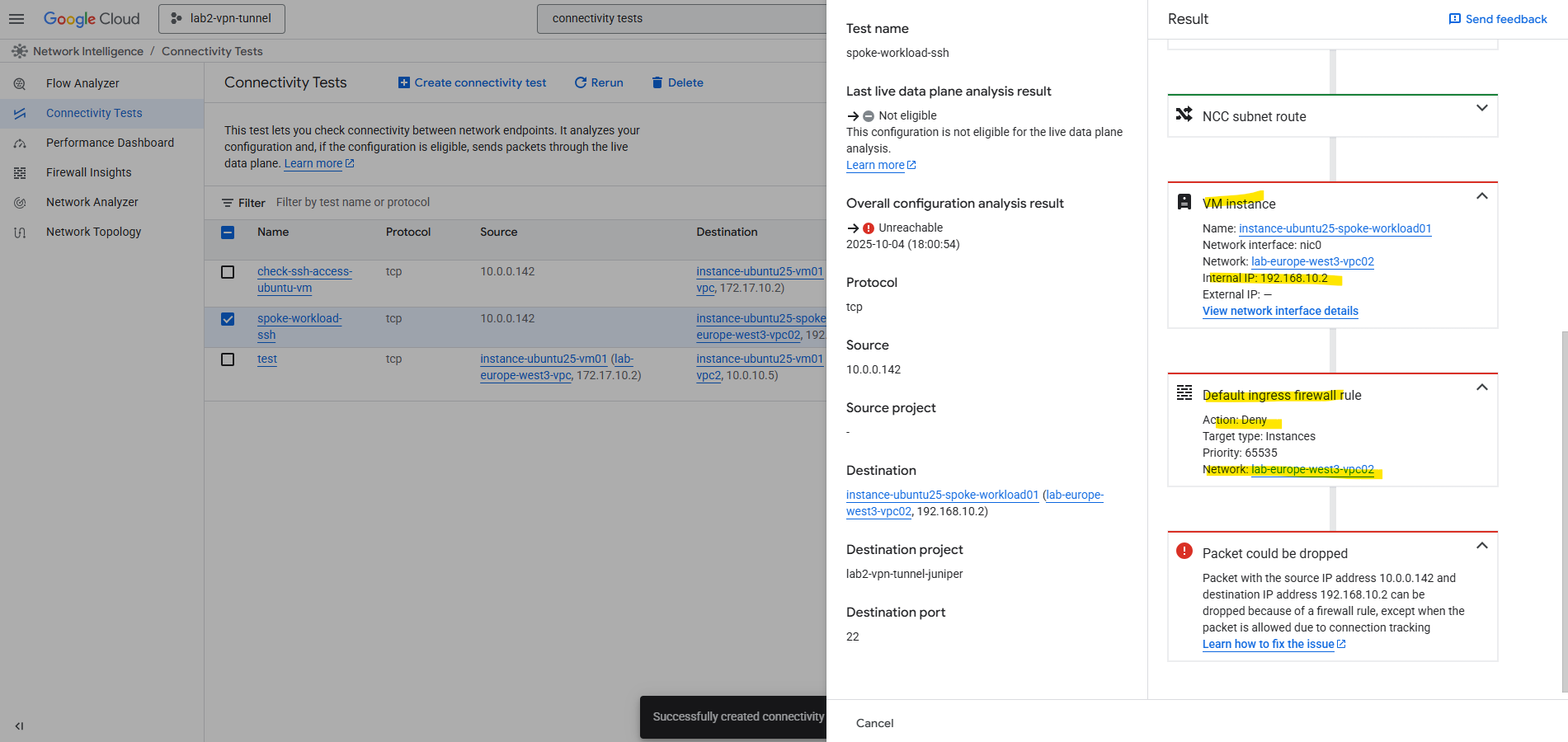
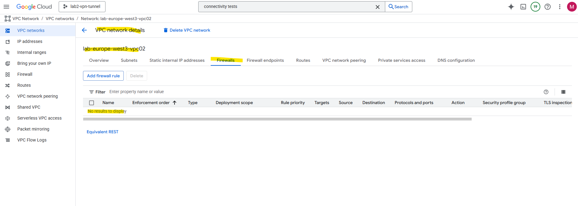
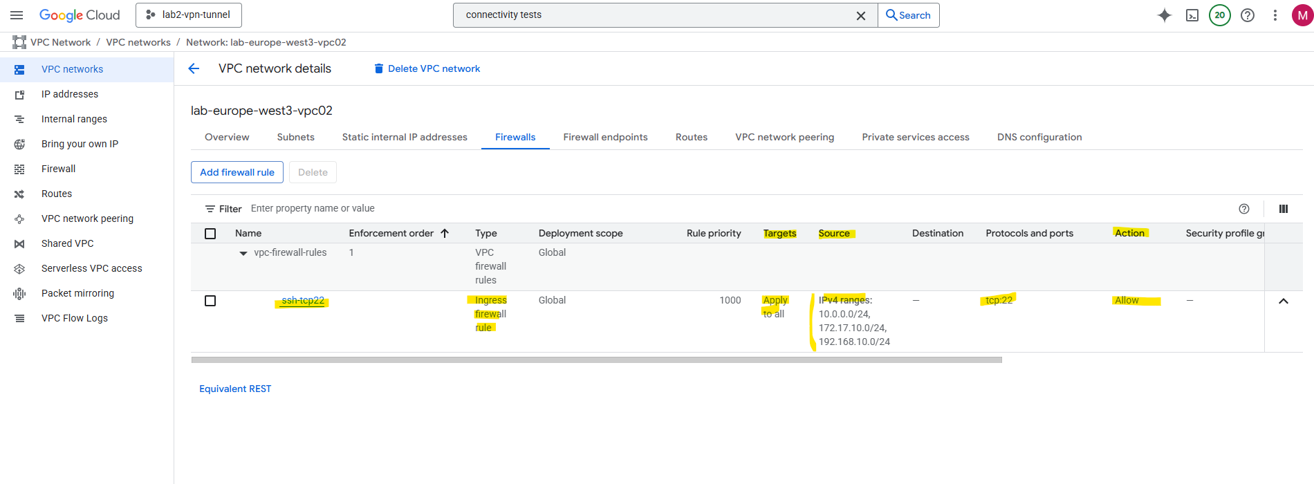
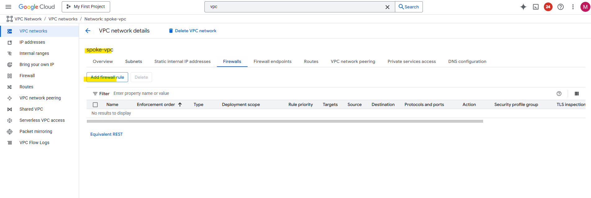
So far no custom rules are created and therefore the default deny all inbound rule will drop the packages from my on-prem VM.
Click on Add firewall rule.
I will allow inbound TCP 22 to all VM instances in this VPC network from all on-prem VMs running in 10.0.0.0/24, further all VM instances in both GCP VPC networks (subnets) in this project.
To enable access to your VM instances by using the SSH in browser from the GCP console as shown in Part 2, we also need to allow traffic from 35.235.240.0/20 (the IAP SSH proxy range) .
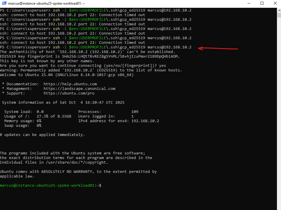
Now I am able to connect to the spoke workload (VM instance) directly from my on-prem network.
This is called transitive routing, traffic from on-prem will be routed through the hub/routing network (acts here as transit network) to the spoke (workload) network where the VM is finally running I am connected to.
Transit routing means using a central network (like a hub VPC/VNet) to route traffic between other connected networks (spokes or on-premises).
In other words, instead of each network connecting directly to all others, traffic passes through the hub, which acts as a shared transit point for connectivity, inspection, or centralized services
When connecting on-premises to GCP using HA VPN with Network Connectivity Center (NCC), traffic can seamlessly transit through the Hub VPC to reach connected spoke VPCs, thanks to NCC’s built-in route propagation.
In contrast, VPC Peering does not support transitive routing, so on-prem traffic terminating in the Hub VPC cannot be forwarded to peered spoke VPCs.
If you rely solely on VPC Peering in a hybrid setup, you’ll need to terminate the VPN connection separately in each VPC that should communicate with on-premises. That means deploying either a native HA VPN or a custom VPN appliance (like pfSense or another NGFW) within every VPC, since traffic can’t transit from one peered VPC to another through the Hub.
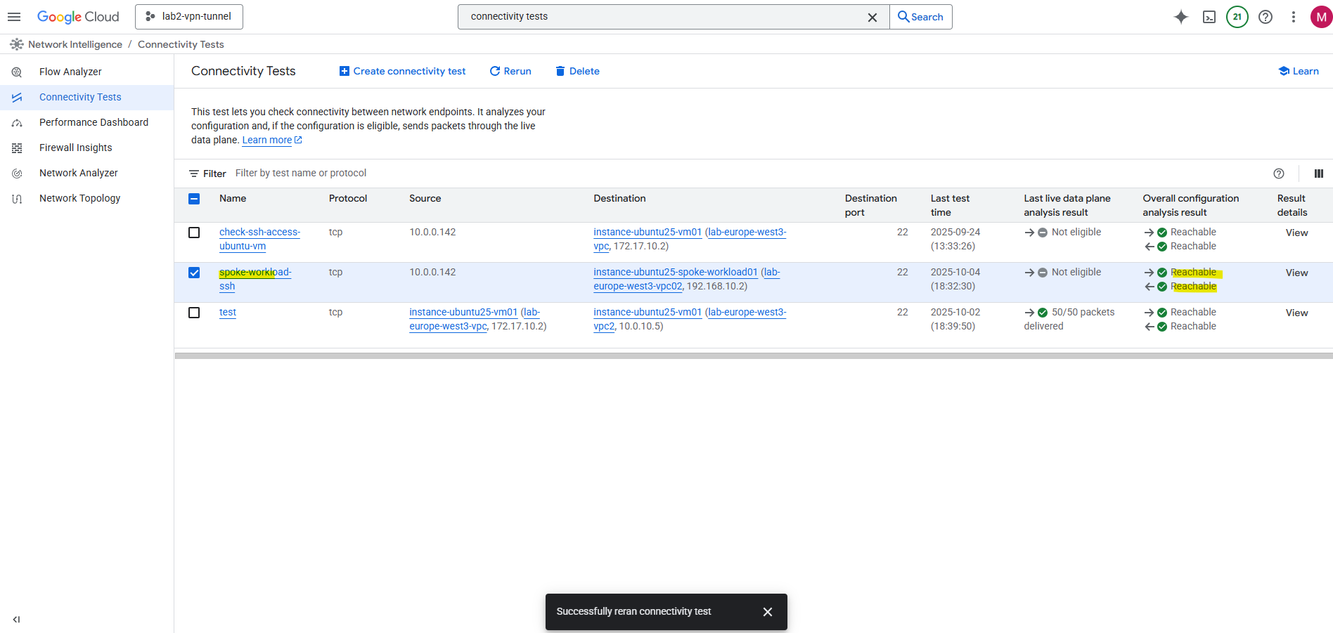
The connectivity test now should also run successful, click on Rerun.
Looks good. As mentioned already, the connectifity test cannot evaluate and inspect if traffic inside the guest OS is allowed. Therefore for troubleshooting also check if the local firewall on your VM instances (workloads) allows the traffic.
The Network Intelligence – Connectivity Tests for example evaluate reachability across the Google Cloud data plane (VPC routing, firewall rules, peering, Cloud NAT, VPN, load balancers, etc.), it will not inspect inside the guest OS.
GCP firewall rules (the VPC-level, project-level rules) are checked while local firewalls inside a VM (like iptables, nftables, firewalld, Windows Defender Firewall) are not checked.
By using VPC Network Peering
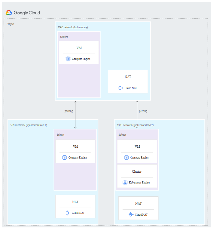
The following diagram shows a hub-and-spoke network that uses VPC Network Peering.
VPC Network Peering enables communication using internal IP addresses between resources in separate VPC networks.
Traffic stays on Google’s internal network and does not traverse the public internet.
!! Note !!
There’s one big limitation when using VPC Network Peering for a hub-and-spoke topology, VPC Network Peering connections don’t allow transitive traffic beyond the two VPC networks that are in a peering relationship like when using as shown previously the Network Connectivity Center.Source: https://cloud.google.com/architecture/deploy-hub-spoke-vpc-network-topology#peering
Source: https://cloud.google.com/architecture/deploy-hub-spoke-vpc-network-topology#peering
Each workload (spoke) VPC network in this architecture has a peering relationship with a central routing (hub) VPC network.
The routing VPC network has a connection to on-premises using Cloud VPN or Cloud Interconnect connections.
All of the VMs in the peered networks can communicate at the full bandwidth of the VMs.
Each workload VPC and the routing VPC network has a Cloud NAT gateway for outbound communication with the internet.
About how to set up Cloud NAT you will see in Part 9.
VPC Network Peering connections are not transitive. In this architecture, the on-premises and workload VPC networks can exchange traffic with the routing network, but not with each other.
To provide exchanging traffic between on-premises and the workload VPC networks, we can use the Network Connectivity Center approach like shown previously.
VPC Peering in GCP is always non-transitive, and this is by design.
In Azure in contrast, VNet peering supports transitive connectivity through the gateway transit feature. By enabling “Allow gateway transit” on the hub VNet and “Use remote gateway” on each spoke, all spokes can share a single VPN or ExpressRoute gateway to reach on-premises.
This makes it easy to build a true hub-and-spoke topology without deploying separate gateways in every VNet, a capability that Google Cloud’s VPC Peering does not natively provide.
Adding Peering between the HA VPN VPC Network and the Workload (spoke) VPC Network
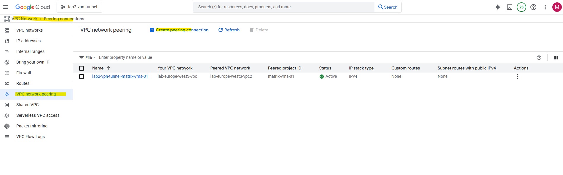
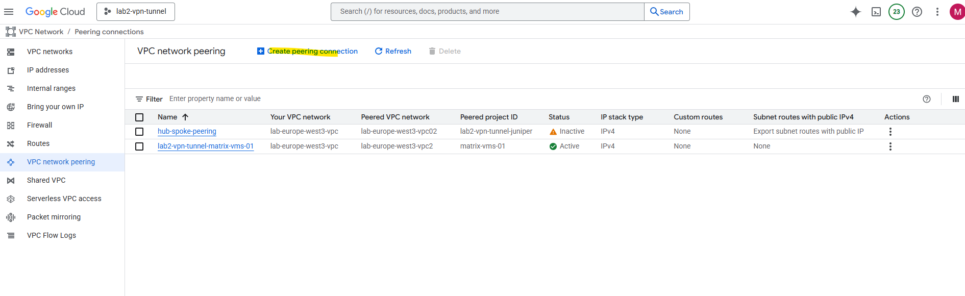
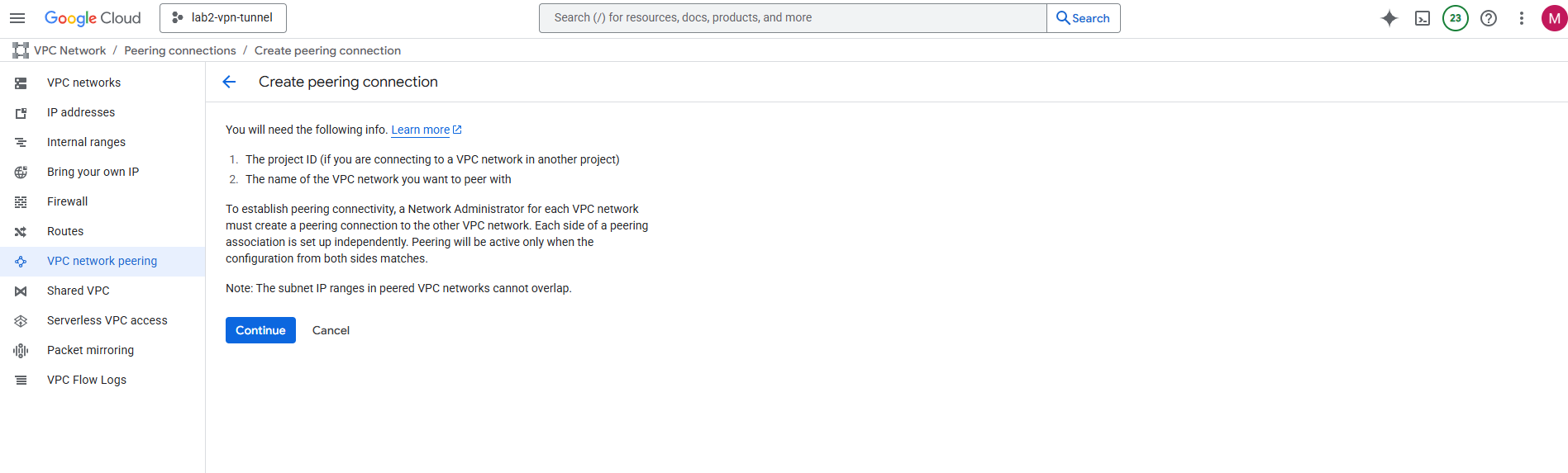
Under VPC Network -> Peering connections, click on Create peering connection.
Click on Continue.
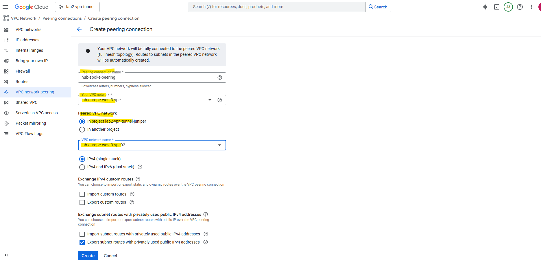
In my case the hub VPC network (where HA VPN was deployed) and the workload (spoke) VPC network are both in the same project.
So we just need the name of both VPC networks.

Select the hub VPC network and spoke VPC network and enter a name for. This will create the peering initiated from the hub network. Click on Create.
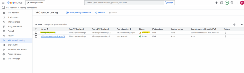
Later we need to create the peering vice versa before both will be connected successfully.
As mentioned before the state will be active we first need to create the peering vice versa.
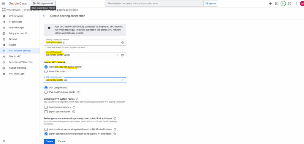
Click on Create peering connection.
Click on Continue.
Select the hub VPC network and spoke VPC network and enter a name for. This will create the peering initiated from the spoke network (vice versa this time). Click on Create.
The peering now is active.
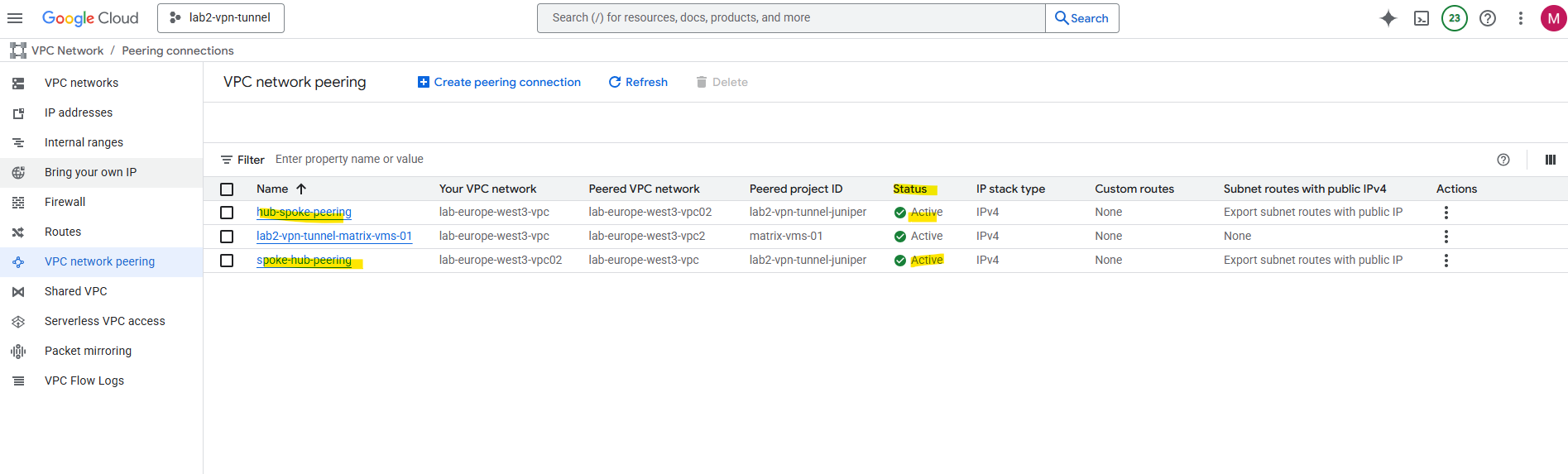
From now on all VMs in the peered networks can communicate with each other. But as mentioned:
VPC Network Peering connections are not transitive. In this architecture, the on-premises and workload VPC networks can exchange traffic with the routing network, but not with each other.
In Google Cloud, using a hub-and-spoke topology built only with VPC peering is not considered a best practice anymore, it’s a valid pattern for small, simple setups, but not scalable or flexible for enterprise-grade networking because:
- Peering is strictly non-transitive, so the hub cannot forward traffic between spokes or to on-prem.
- You’d need one VPN per spoke if you want each VPC to reach on-prem, that scales poorly.
- Each new VPC requires another direct peering connection with the hub
- Routes must be managed per peering link (no central propagation).
- There’s no central place for logging, monitoring, or firewall enforcement across peers.
- Shared services (e.g., DNS, proxies, NAT, security appliances) in the hub are not reachable by spokes through peering.
By using Cloud VPN
And as mentioned, VPC Network Peering connections don’t allow transitive traffic beyond the two VPC networks that are in a peering relationship.
To support transitive traffic we can also use Cloud VPN besides the Network Connectivity Center architecture shown previously.
Cloud VPN also overcome the limitations of VPC Network Peering, but the total bandwidth (ingress plus egress) between networks is limited to the bandwidths of the tunnels. Additional tunnels can be added to increase bandwidth.
About how to set up Cloud VPN which offers two types of Cloud VPN gateways, HA VPN and Classic VPN, you can read my following post. In this post I was setting up a site-to-site IPSec VPN between my on-prem lav environment and GCP but finally works the same like when connecting two GCP VPC networks.
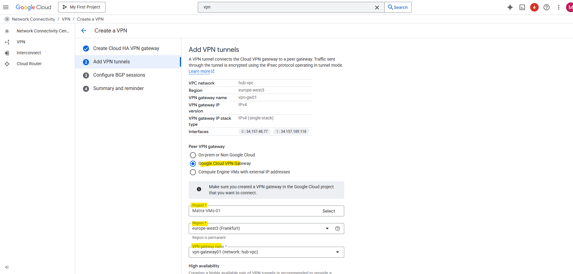
When setting up the VPN tunnel between two GCP projects/VPC networks, we need to select for the peer VPN gateway on both sides (projects/VPC networks) always Google Cloud VPN Gateway.
I will connect here finally two different projects (each consists of a hub and spoke network) where their hub networks are connected through Cloud VPN (HA VPN).
Technically you can use Cloud VPN within a single GCP project to connect different VPC networks, including hub-and-spoke setups, but it’s not the typical or recommended approach.
GCP allows Cloud VPN between any two VPC networks, even if they belong to the same project, as long as those networks are not connected via VPC peering (since peering and VPN are independent mechanisms).
Each VPC would need its own Cloud VPN gateway, and you’d establish a tunnel between them, just like between two separate environments.
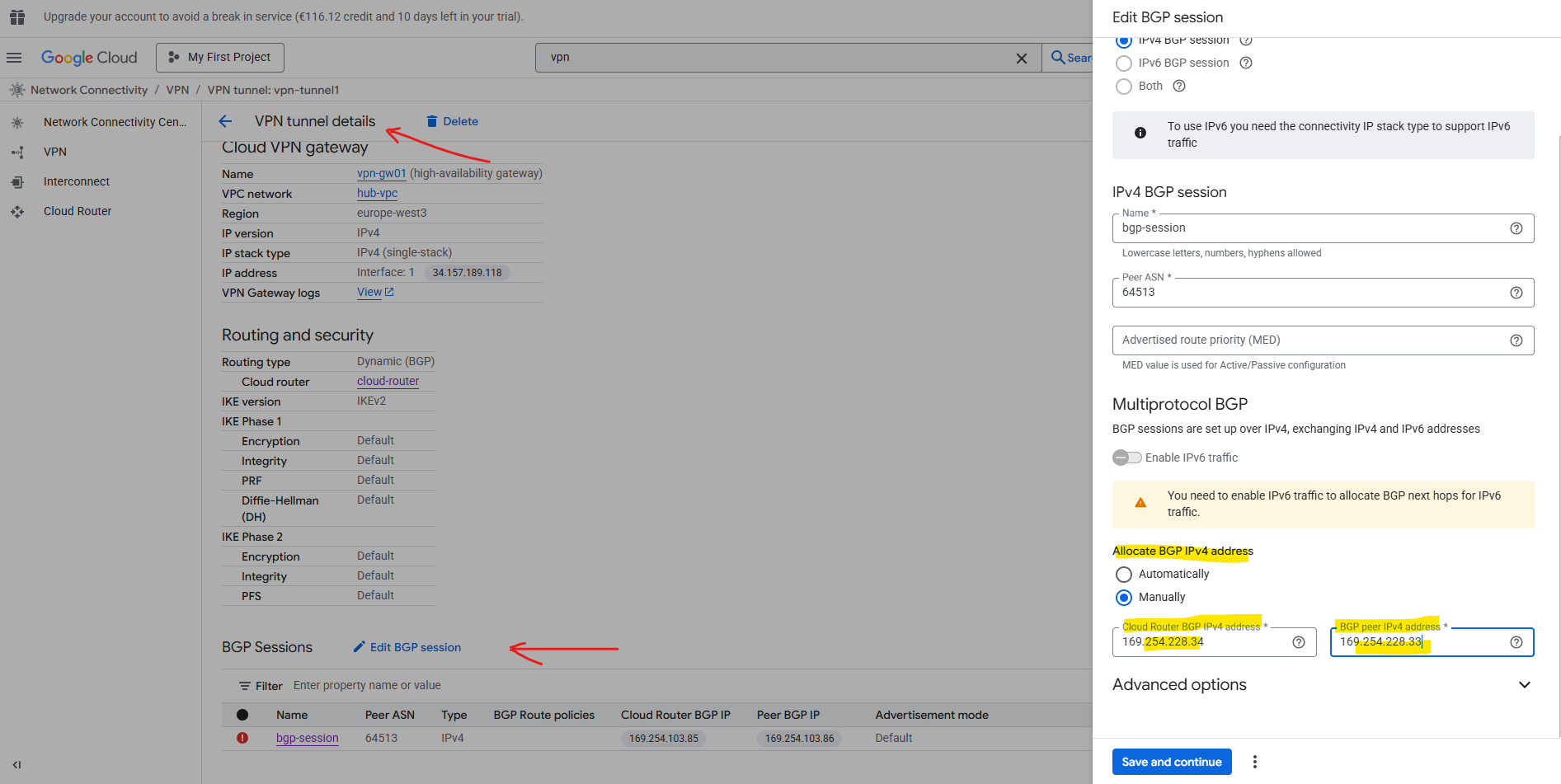
For the BGP session adjust the BGP IP addresses to be finally in the same /30 subnet.
So far on both sides just each hub VPC network is advertised to the other side (project).
The spoke VPC networks are not advertised so far.
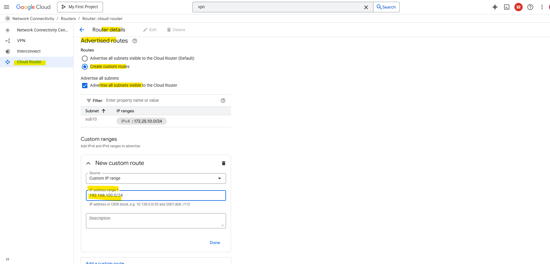
By default, the hub only advertises subnets from its own VPC. To include spoke routes, select Create custom routes on the router details page as shown below.
Check Advertise all subnets visible to the Cloud Router and adding the workload subnet associated with the spoke.
After adding the spoke subnets on both sides (projects), finally all subnets are advertised to the other side.
To now test if the workloads (VM instances) in both spoke networks on each side can reach each other through the VPN tunnel and will be routed through the peer hub/routing network successfully, we first need to allow inbound traffic on each spoke VPC network.
On both spoke VPC networks I will add a new firewall rule.
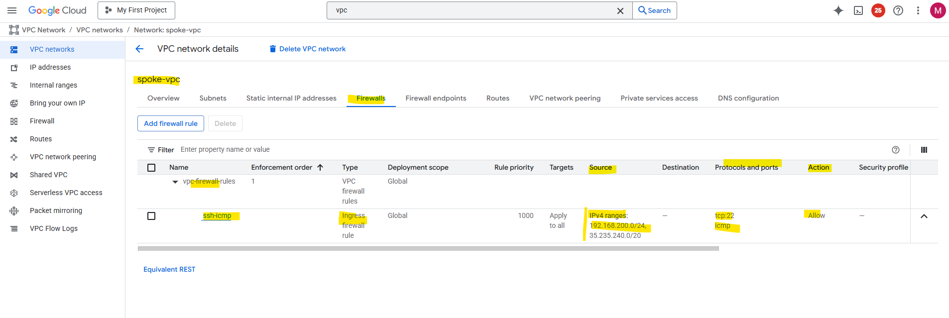
For testing purpose I will create just one rule allowing ICMP (Echo request and reply messages) and SSH TCP 22 inbound from the source spoke network.
For the source I will allow the subnet 192.168.200.0/24 which is the address range from the spoke VPC network on the other side (project). The same I will configure on the other spoke VPC network vice versa.
To enable access to your VM instances by using the SSH in browser from the GCP console as shown in Part 2, we also need to allow traffic from 35.235.240.0/20 (the IAP SSH proxy range).
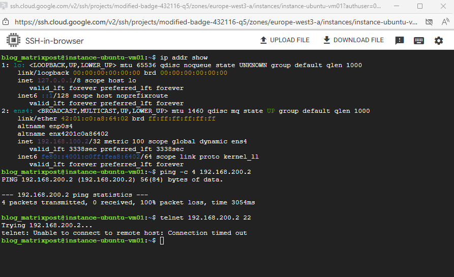
Even the tunnel is up and running, we allowing inbound ICMP and SSH traffic, I cannot connect between both spoke VPC network workloads.
So I will run a quick connectivity test first.
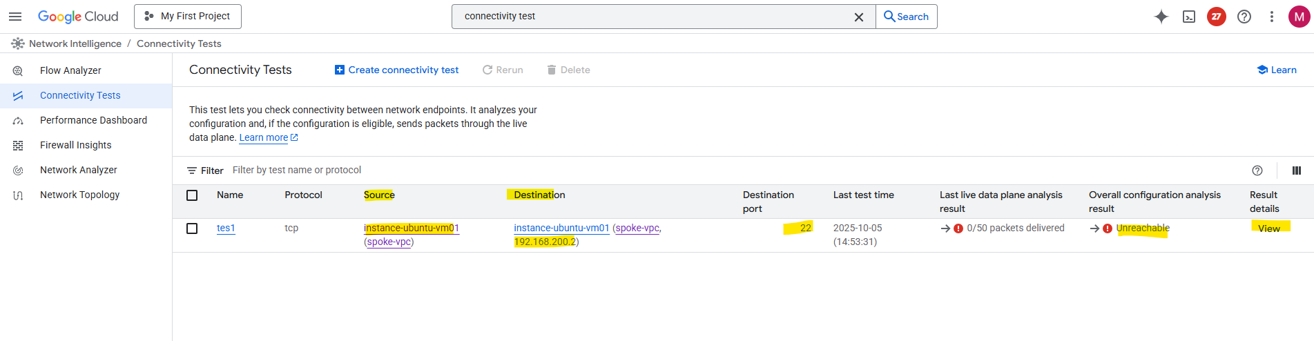
There must be something wrong with the routing. So far outbound traffic to the spoke VPC network in my other project will not be routed through the Cloud VPN tunnel and instead is sent to the internet.
The reason for is simple, I just forgot to peer both spoke VPC Networks with its own hub VPC network and therefore couldn’t use the hub/routing VPC network’s VPN gateway and tunnel.
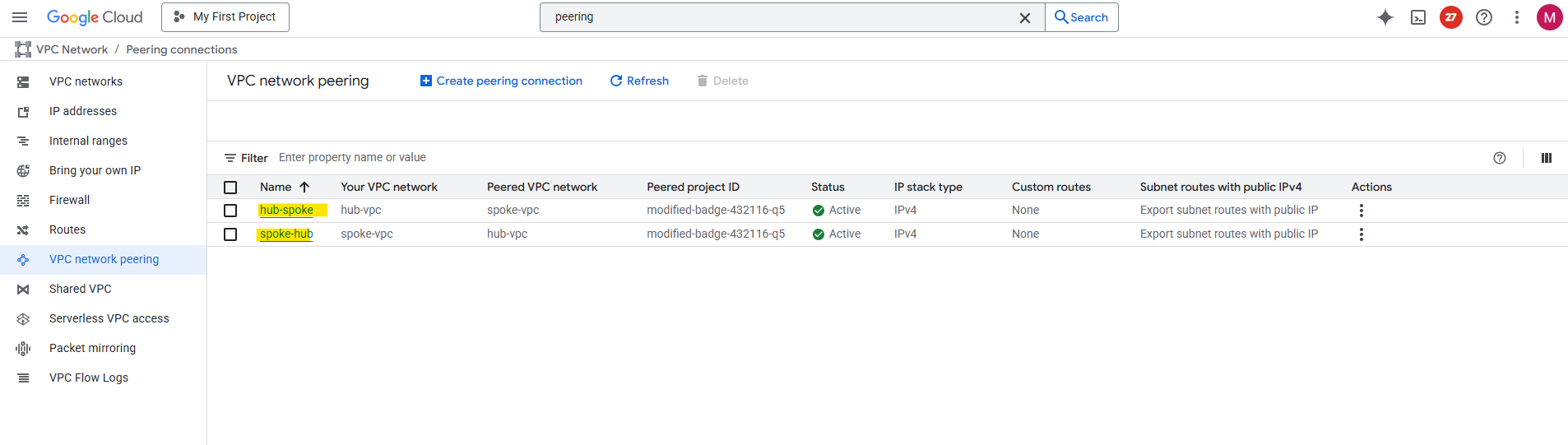
So I will create a new peering between the spoke and hub VPC network on each side (project).
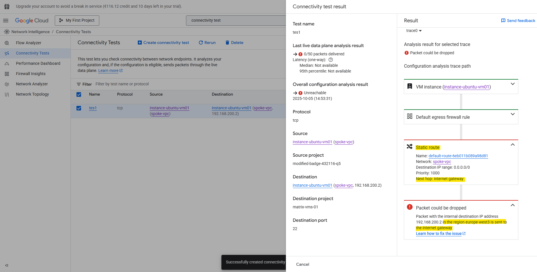
When running the connectivity test again, I will run into the same error, traffic initiated from the spoke VPC network will still be sent to the internet instead VPN tunnel.
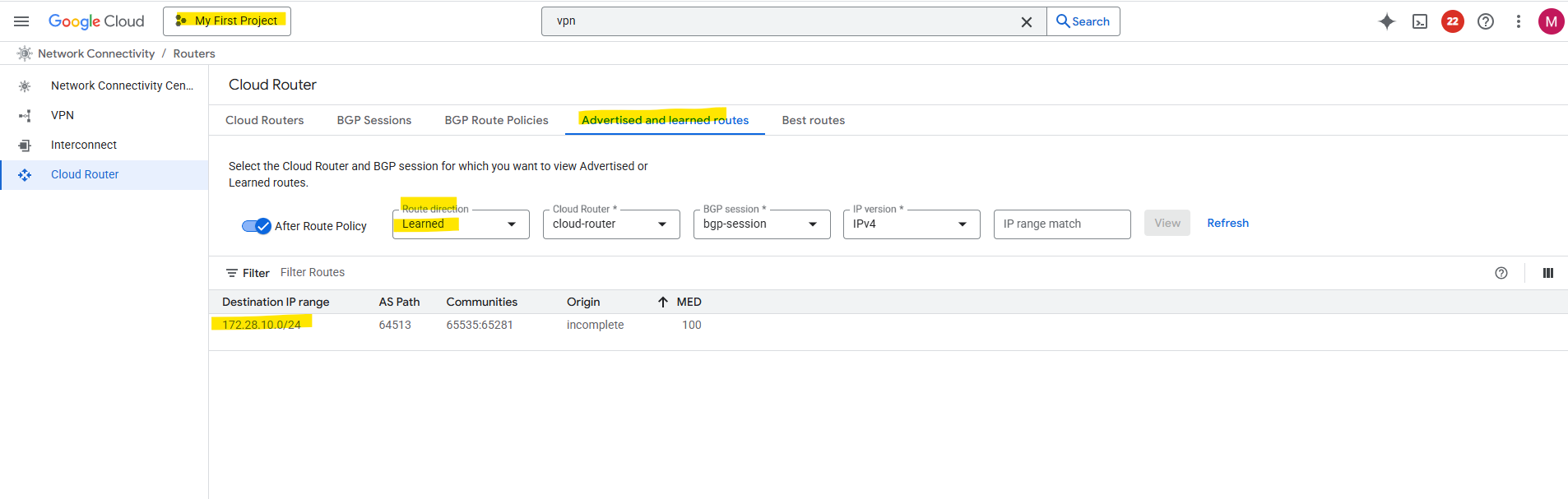
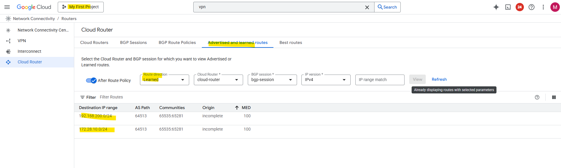
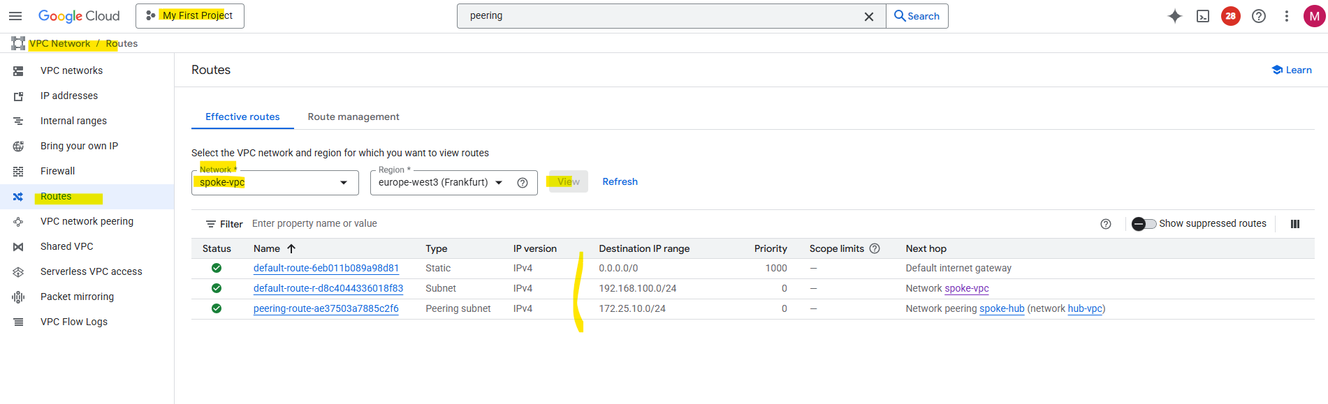
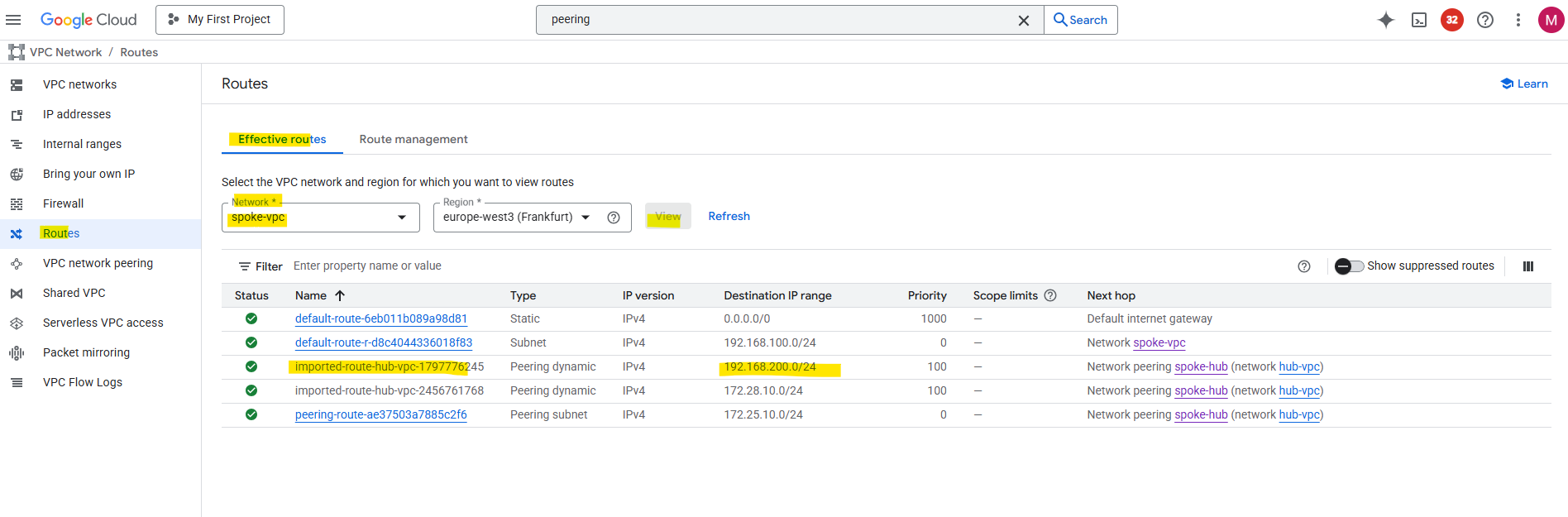
So next I will check the source spoke VPC networks effective routes. Below the destination spoke VPC network from the other side (project) with 192.168.200/24 is missing.
That’s the reason why initiated outbound traffic will be routed to the default internet gateway instead to the hub/routing VPC network and vpn tunnel.
To solve this, in each hub and spoke VPC on both sides (projects), enable custom route exchange by checking the following two check boxes with Import custom routes and Export custom routes.
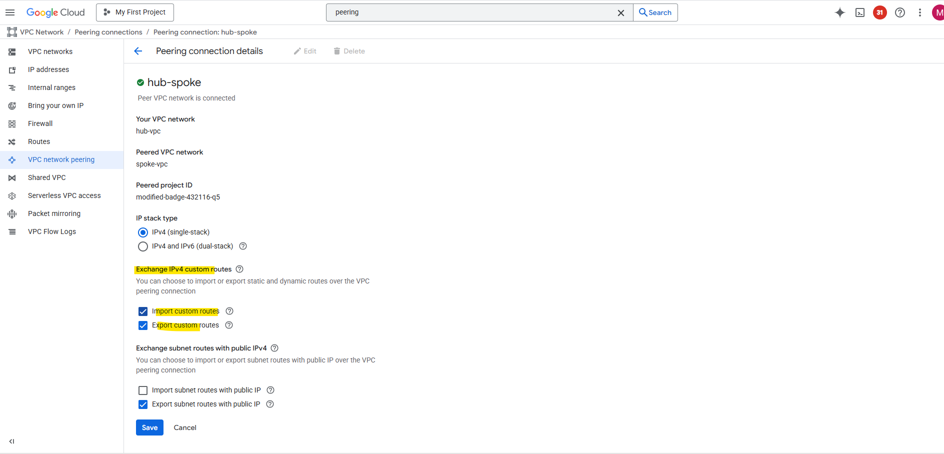
Now the route to the destination spoke VPC network (192.168.200/24) on the other side (project) is advertised from the hub/routing VPC network to its peered spoke VPC network.
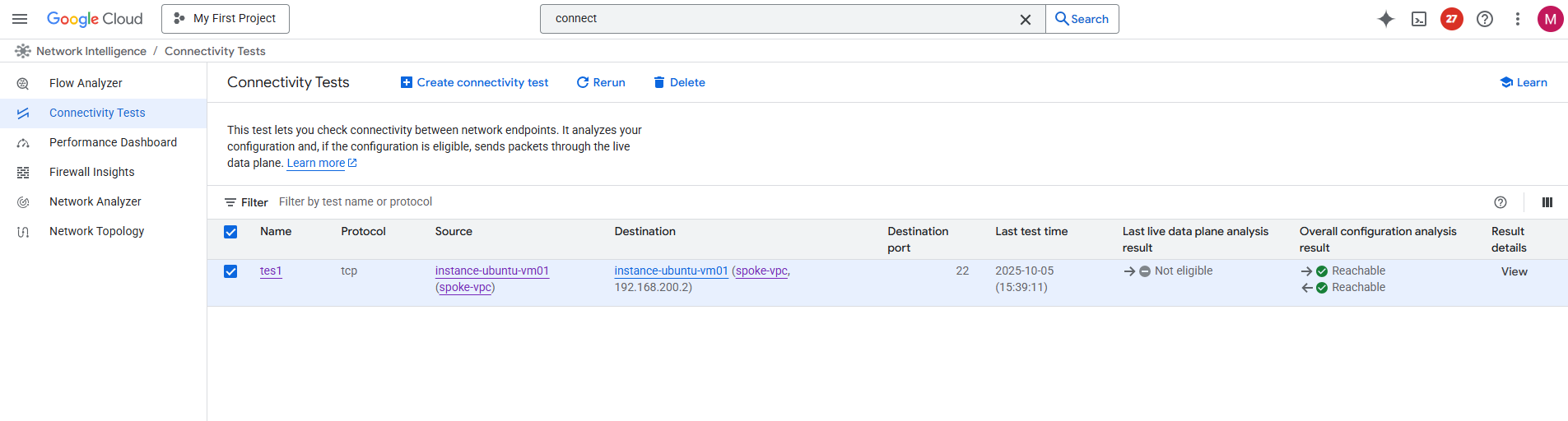
Before I will try to ping (Echo request messages) the VM instance (workload) on the other side (project) and spoke VPC network, I will first run again the connectivity test.
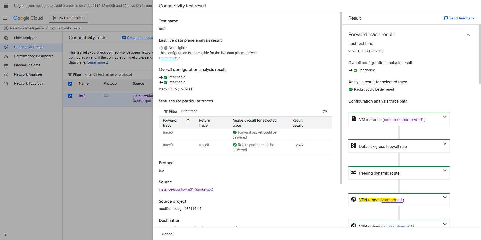
Et voilà, looks good now and regarding the connectivity test traffic can now be sent from the source spoke VPC network and workload successfully to the destination spoke VPC network and workload.
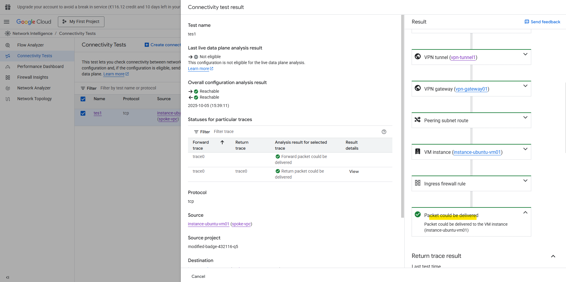
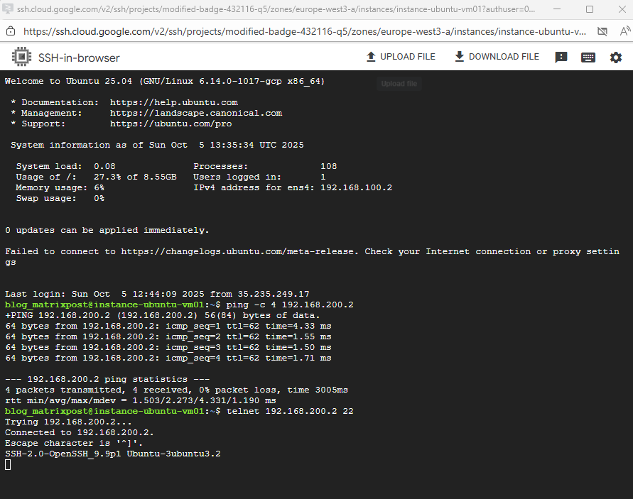
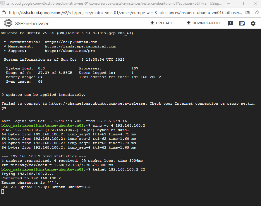
Also real traffic initiated from both sides (projects) and workloads will now succeed.
The GCP Network Intelligence Center’s Connectivity Test does not send real traffic through the data plane.
Instead, it performs a control-plane analysis based on your current configuration (routes, firewall rules, VPN tunnels, peering, forwarding rules, etc.).
It just simulates the path that packets would take, using Google’s internal network model. It checks for misconfigurations such as missing routes, denied firewalls, or unreachable next hops.
It does not generate or transmit actual packets between your VMs, VPNs, or on-prem devices.
Understanding Transit Behavior Between Spokes and the Hub in Google Cloud
In GCP, the VPC Peering is strictly non-transitive, meaning traffic from one spoke cannot pass through a peered Hub VPC to reach another spoke (for example, Spoke A → Hub ← Spoke B). Even if both spokes are peered to the same Hub, Google’s Andromeda SDN enforces this restriction, packets entering through one peering connection cannot leave through another.
A VPC Peering connection is a network-to-network link that explicitly disallows transitive routing. Packets entering the Hub via one peering connection cannot be forwarded out through another, this is enforced by Andromeda’s routing domain boundaries at the VPC edge.
However, HA VPN attachments are different. They’re not peering links, they’re edge gateways that terminate IPsec tunnels and integrate directly into the VPC routing table via Cloud Router. When traffic from a peered spoke reaches the Hub and matches a route learned through HA VPN (advertised by Cloud Router), Andromeda handles the forwarding entirely within the Hub VPC’s routing context.
In this design, traffic can flow seamlessly between Spoke A and Spoke B through the Hub’s VPN attachments, because routing occurs via Cloud Router and the VPN control plane, not through VPC Peering.
In short, VPC Peering cannot provide transitive routing, but HA VPN + Cloud Router can, effectively turning your Hub into a secure, BGP-driven transit layer for multi-spoke communication.
Unlike GCP, where VPC Peering is non-transitive, in contrast Azure VNet Peering fully supports transitive routing when combined with a hub-and-spoke topology.
This means traffic from Spoke A can reach Spoke B through the Hub VNet without requiring a separate VPN or BGP configuration, as long as “Use remote gateway” and “Allow gateway transit” options are enabled on the peering links.
In short, Azure’s native peering allows the Hub to act as a true transit router, while in GCP you need Network Connectivity Center (NCC) or HA VPN + Cloud Router to achieve the same result.
In AWS, standard VPC Peering is also non-transitive, similar to GCP. To enable spoke-to-spoke communication through a hub, you need to use AWS Transit Gateway, which provides a central routing layer for connected VPCs and VPNs, effectively the AWS equivalent of GCP’s NCC.
Subnet Planning Best Practices
In Google Cloud, subnetting is not just about allocating IP ranges, it’s about long-term scalability and minimizing rework as your environment grows.
Each subnet is regional, so thoughtful IP planning helps you expand or peer networks without overlap.
Best practices:
- Plan for growth: Choose CIDR ranges large enough to accommodate future workloads. Renumbering subnets later can be painful.
- Avoid overlapping ranges: Especially important for hybrid or multi-VPC designs — overlapping CIDRs break peering and complicate VPN routing.
- Use consistent CIDR schemes: For example, /20 for production, /22 for dev/test, and reserved ranges for private services.
- Separate subnets by function or tier: Isolate front-end, back-end, and management workloads into dedicated subnets for cleaner firewall segmentation.
- Use secondary IP ranges for GKE or proxy subnets: Reserve these early to avoid address conflicts later
Governance: Keeping Your GCP Network Under Control
Building a solid GCP network is only half the story, keeping it consistent and well-managed as teams, projects, and environments grow is just as critical. Operational governance defines how networks are maintained, monitored, and secured over time.
Best practices:
- Centralize network ownership: Use Shared VPC to delegate subnet usage while keeping control of routing, firewalls, and peering in a dedicated host project.
- Apply consistent IAM and policy controls: Restrict who can create or modify networks, VPNs, and firewalls using roles like compute.networkAdmin or custom least-privilege roles.
- Use labels and folders for structure: Apply labels (e.g., env=prod, region=europe-west3) and folder hierarchies to organize billing and policy inheritance.
- Monitor continuously: Leverage VPC Flow Logs, Firewall Insights, and Network Intelligence Center for visibility and anomaly detection.
- Automate compliance: Use Organization Policies to enforce constraints (like disallowing public IPs) and Infrastructure as Code (Terraform or Deployment Manager) for repeatable configuration.
Links
Hub-and-spoke network architecture
https://cloud.google.com/architecture/deploy-hub-spoke-vpc-network-topologyPreset connectivity topologies
https://cloud.google.com/network-connectivity/docs/network-connectivity-center/concepts/connectivity-topologiesNetwork Connectivity Center overview
https://cloud.google.com/network-connectivity/docs/network-connectivity-center/concepts/overviewCloud VPN overview
https://cloud.google.com/network-connectivity/docs/vpn/concepts/overview