Mastering GCP Virtual Machines – Part 9 (Outbound Internet Access)
If your VMs need general outbound internet (patching, repo downloads, external APIs), and you don’t want public IPs → Cloud NAT is the way to go.
Cloud VPN does not support routing public internet traffic through on-premises like in Azure, it is designed for secure communication between private networks.
If you need centralized inspection in GCP, you’d typically deploy firewall/inspection appliances inside a hub VPC like shown below (Google’s Counterpart to Azure Firewall).
By default, VMs in a VPC without an external IP can’t reach the public internet, which is usually desirable for secure architectures. There are several ways to enable or control egress access which we will all see below.
You can also read my following post about building a Centralized Egress and Hybrid Connectivity Hub by using the Network Connectivity Center (NCC).
And the following about running pfSense in Google Cloud Platform (GCP).
- Set up Cloud NAT (Recommended)
- Assign ephemeral/static external IPs to VMs
- Proxy via Google services
- Google's Counterpart to Azure Firewall
- Deploy a NGFW appliance
- Deploying Workload VM in the Spoke VPC Network
- Deploying an Internal Passthrough Network Load Balancer (ILB)
- Create a Custom Route (new Default Internet Gateway) in the Spoke VPC
- Create a Custom Route (new Default Internet Gateway) in the Hub VPC itself
- Final Thoughts about the ILB Option as valid Next Hop
- Links
Set up Cloud NAT (Recommended)
Cloud NAT is a distributed, software-defined managed service. It doesn’t depend on any VMs in your project or a single physical gateway device.
You configure a NAT gateway on a Cloud Router, which provides the control plane for NAT, holding configuration parameters that you specify.
Google Cloud runs and maintains processes on the physical machines that run your Google Cloud VMs.
Source: https://cloud.google.com/nat/docs/overview
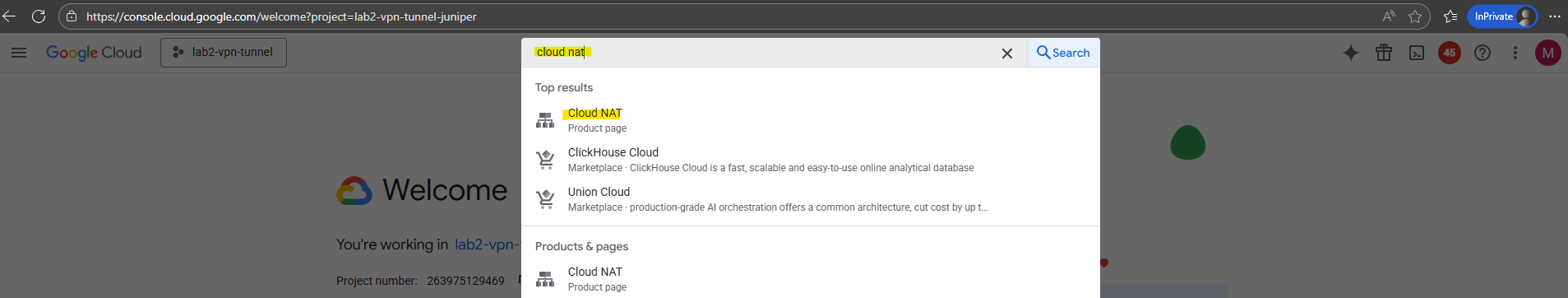
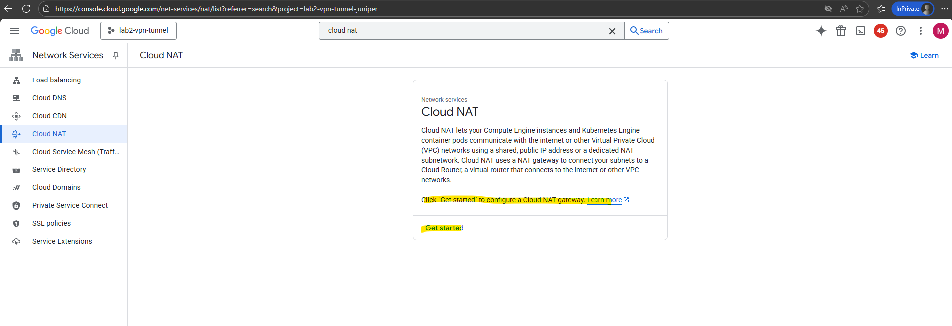
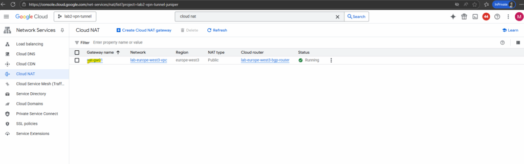
Click “Get started” to configure a Cloud NAT gateway.
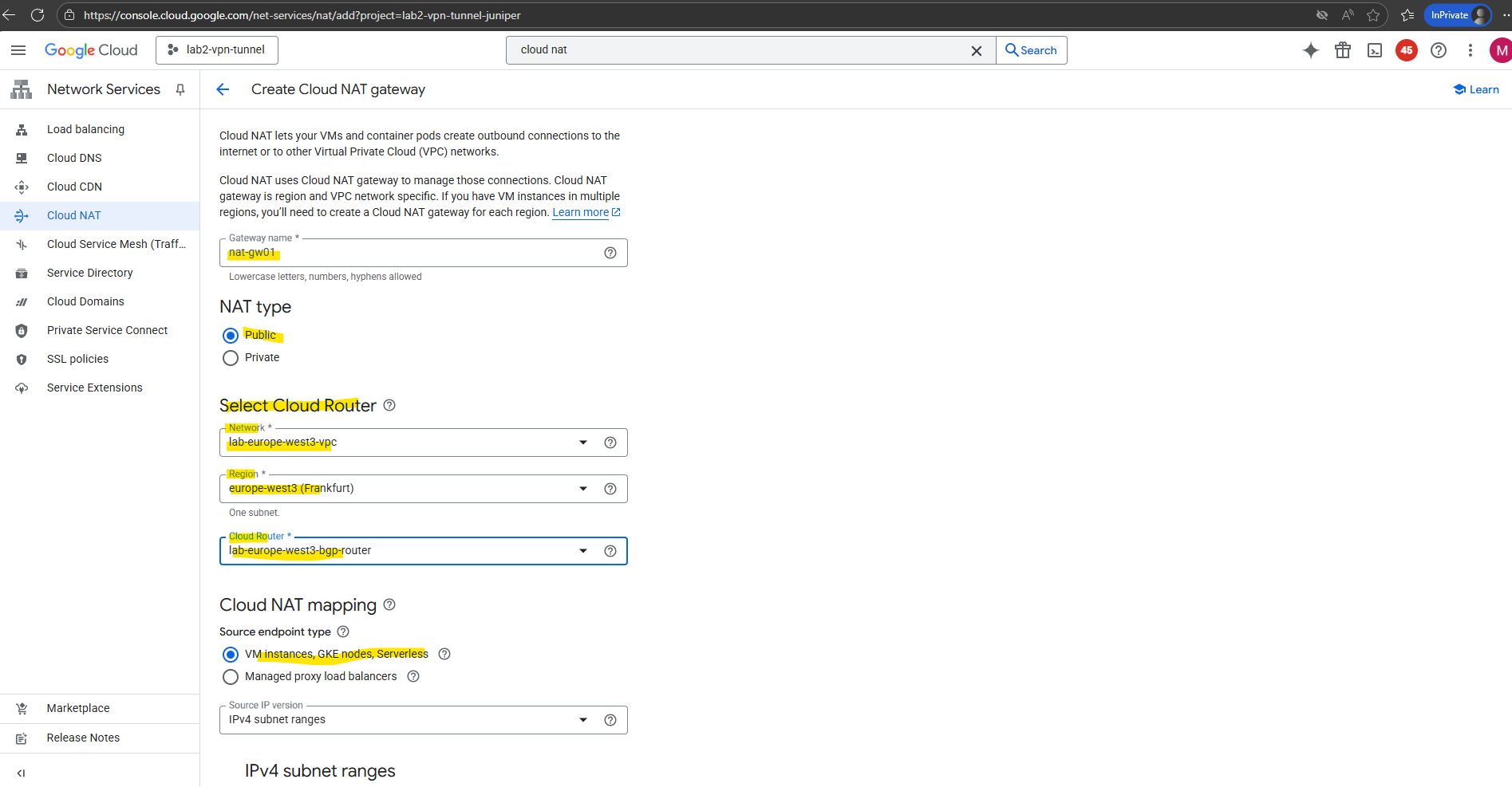
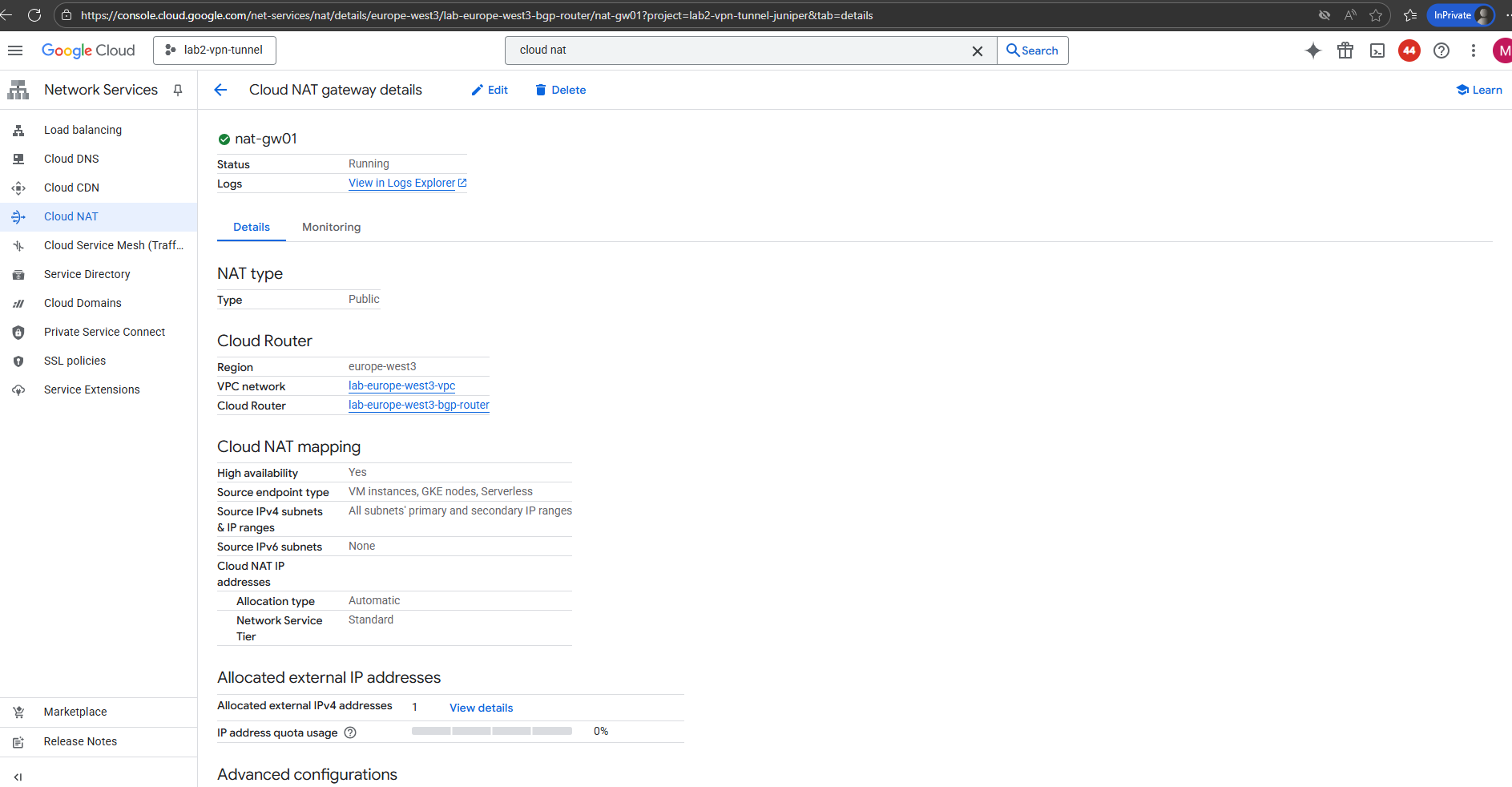
Enter a name for the NAT gateway, the VPC network and region where you want to configure your Cloud NAT gateway and select the desired cloud router.
Cloud NAT uses the Cloud Router resource to group the Cloud NAT gateway configurations together. Cloud NAT is not actually performed by the Cloud Router. If a Cloud Router is used for both BGP and NAT, the Cloud NAT gateways do not consume any resources on the Cloud Router and will not affect the router’s performance.
I will use my cloud router which I was creating to set up HA VPN (IPSec VPN tunnel) between my on-prem lab environment and GCP shown here.
HA VPN requires BGP which will be provided by the cloud router.
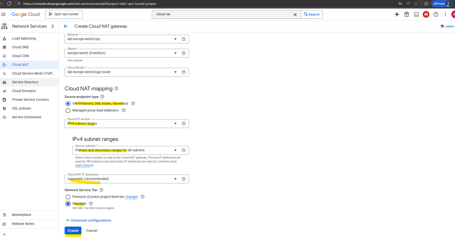
Finally click on Create.
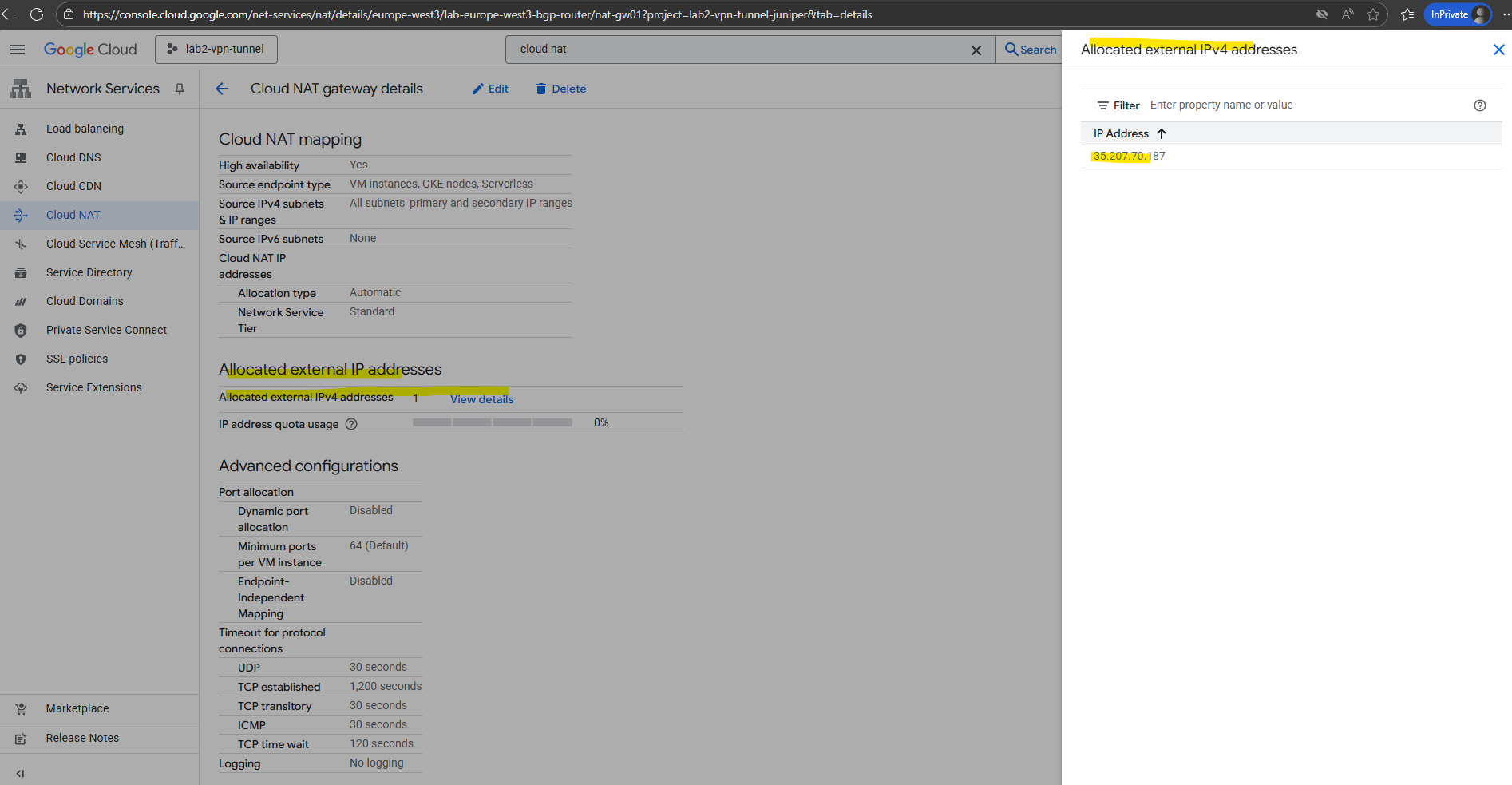
From now on all VM instances running in the VPC network we deployed Cloud NAT to, will have outbound internet access. To test if they will really use our new Cloud NAT, we can first determine the public IP address below.
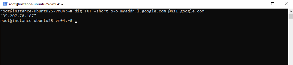
Then quick test on one of the VM instances.
# dig TXT +short o-o.myaddr.l.google.com @ns1.google.com
Assign ephemeral/static external IPs to VMs
To provide outbound internet access, we can also assign it either an ephemeral or a reserved static external IP address.
An ephemeral IP is temporary and released when the instance stops, making it suitable for short-lived or test workloads.
A reserved static IP, on the other hand, remains permanently associated with your project, ideal for production systems, whitelisting, or DNS records that require a fixed, predictable address.

Compared to assigning an external IP directly to a VM, using a NAT gateway (Cloud NAT) allows private instances without public IPs to reach the internet securely through address translation.
This approach reduces your public attack surface, centralizes egress control, and simplifies firewall management.
In contrast, giving each VM its own ephemeral or static public IP exposes it directly to the internet and should generally be avoided outside of specific, tightly controlled use cases.
Proxy via Google services
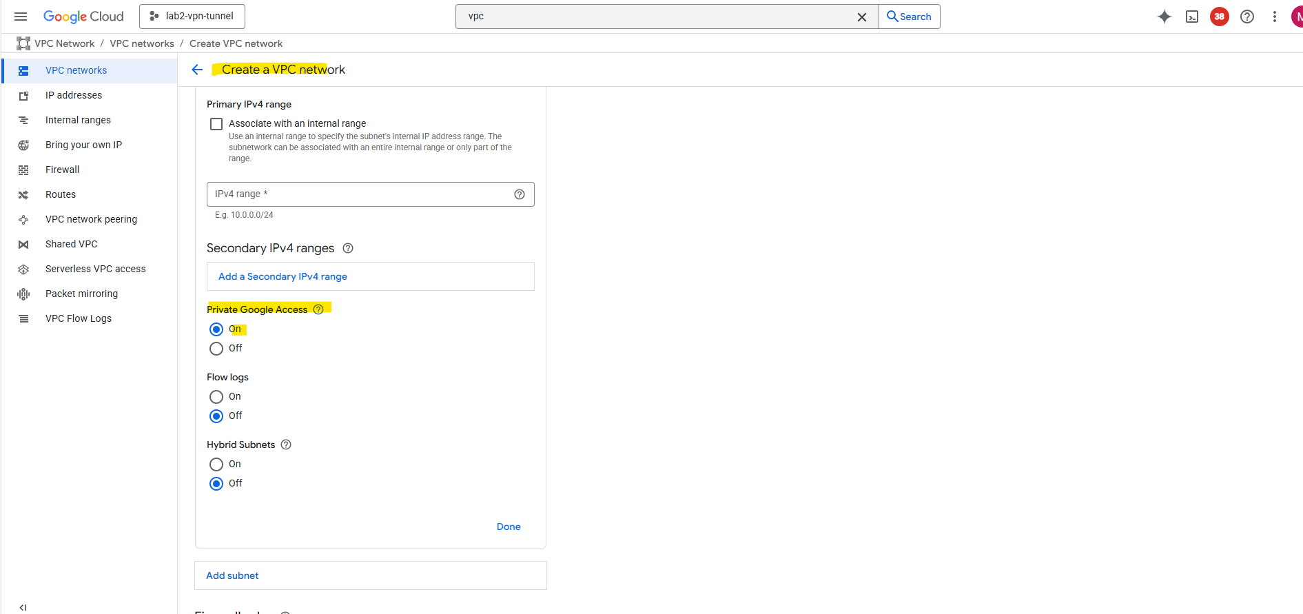
VM instances that only have internal IP addresses (no external IP addresses) can use Private Google Access.
They can reach the external IP addresses of Google APIs and services (including the search engine on https://www.google.de). The source IP address of the packet can be the primary internal IP address of the network interface or an address in an alias IP range that is assigned to the interface.
If you disable Private Google Access, the VM instances can no longer reach Google APIs and services; they can only send traffic within the VPC network.
But it doesn’t cover general internet, just Google services.
You enable Private Google Access on a subnet by subnet basis; it’s a setting for subnets in a VPC network.
To enable a subnet for Private Google Access and to view the requirements, see Configure Private Google Access.
Private Google Access has no effect on instances that have external IP addresses. Instances with external IP addresses can access the internet, according to the internet access requirements. They don’t need any special configuration to send requests to the external IP addresses of Google APIs and services.
Source: https://cloud.google.com/vpc/docs/private-google-access
Google’s Counterpart to Azure Firewall
While Azure ships with a native managed NGFW (Azure Firewall), Google Cloud’s native tools stop at NSG-like functionality with VPC firewall rules.
If you want a real one-to-one counterpart to Azure Firewall’s centralized next-gen firewall capabilities, you’ll need to deploy a partner NGFW appliance from the Google Cloud Marketplace.
When you need deep packet inspection, URL filtering, threat prevention, or advanced logging, you can route outbound traffic through a Next-Generation Firewall (NGFW) instead of (or in addition to) Cloud NAT.
This design is common in regulated or enterprise environments that require centralized inspection of all internet-bound traffic.
Google Cloud Marketplace offers several certified virtual firewall appliances:
| Vendor | Common Product | Notes |
|---|---|---|
| Palo Alto Networks | VM-Series NGFW | Most widely used; integrates with Panorama, supports HA pairs, and integrates with Cloud Router/HA VPN. |
| Check Point | CloudGuard Network Security | Good hybrid integration; supports dynamic objects and centralized policy management. |
| Fortinet | FortiGate-VM | Feature-rich and strong performance for medium to large deployments. |
| Cisco | Secure Firewall Threat Defense (FTDv) | Suitable if you already use Cisco SecureX or ASA in hybrid setups. |
| Juniper | vSRX | Full NGFW feature set and fits well with hybrid Juniper infrastructures. |
The typical egress inspection pattern is a centralized hub VPC (by using the Network Connectivity Center) where the NGFW resides.
In a hub-and-spoke architecture, the hub serves as the central connectivity point for all spoke VPCs, typically hosting shared services, gateways, and security appliances.
You can design the hub as a single VPC containing all gateways and proxies, or split it into two separate VPCs, a trusted and an untrusted network, to better isolate internal traffic from Internet-facing components and enforce stricter security boundaries.
In this post, I’ll use a simple Ubuntu VM as a lightweight gateway workaround to demonstrate the hub-and-spoke concept without the complexity of a full firewall appliance.
This setup is intended purely for lab and demonstration purposes, making it easier to visualize routing and traffic flow. In a production environment, you’d ideally replace this with a proper NGFW setup, such as the one shown in my “Deploying pfSense in Google Cloud” post, to provide real security, inspection, isolation (splitting the Hub in two VPCs → trusted and untrusted VPC) and policy control.
All spoke VPCs (by using the Network Connectivity Center) route their internet-bound traffic to the firewall subnet, which then forwards the traffic to the internet (via Cloud NAT or its own external IP).
For the hub and spoke topology we need to use the Network Connectivity Center because usual VPC peering doesn’t support transitive connectivity. So using the hub VPC as transit network for traffic initiated from the spoke VPC and destined for the internet is not supported.
VM (Spoke) → Network Connectivity Center (Hub + Spoke Mesh topology) → Hub Firewall Subnet → NGFW → Cloud NAT / External IP → Internet
I was already creating a hub and spoke VPC network.
About how to set up a Hub-and-spoke by using the Network Connectivity Center you will see in Part 8 and directly here.
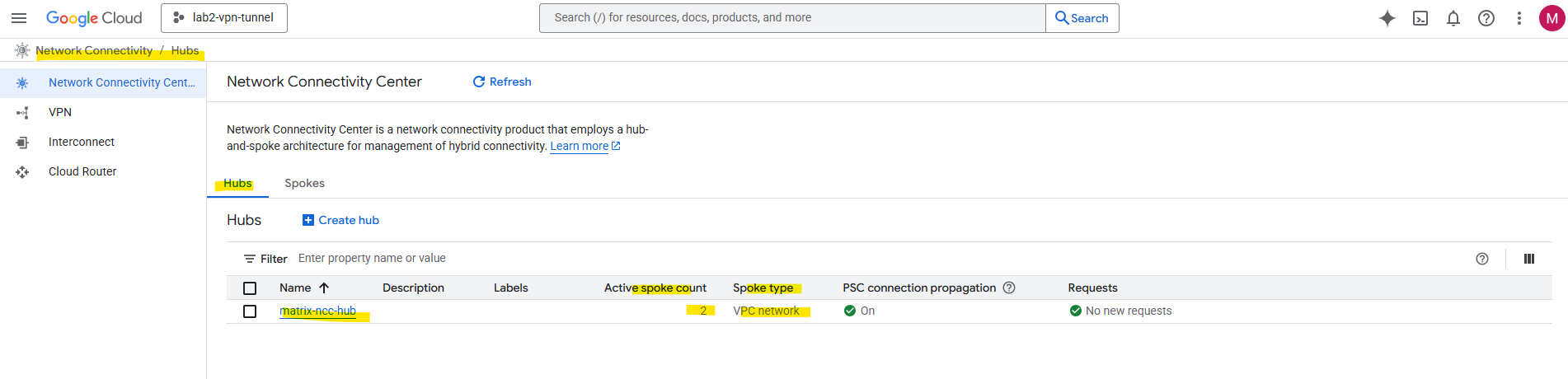
Finally we assign our existing hub and spoke VPC network in the Network Connectivity Center as new hub/spoke in a mesh topology.
Creating a hub and spoke mesh topology in Network Connectivity Center will support transitive routing.
Transit routing means using a central network (like a hub VPC/VNet) to route traffic between other connected networks (spokes or on-premises).
In other words, instead of each network connecting directly to all others, traffic passes through the hub, which acts as a shared transit point for connectivity, inspection, or centralized services.
In our case here inspection and centralizing internet traffic.
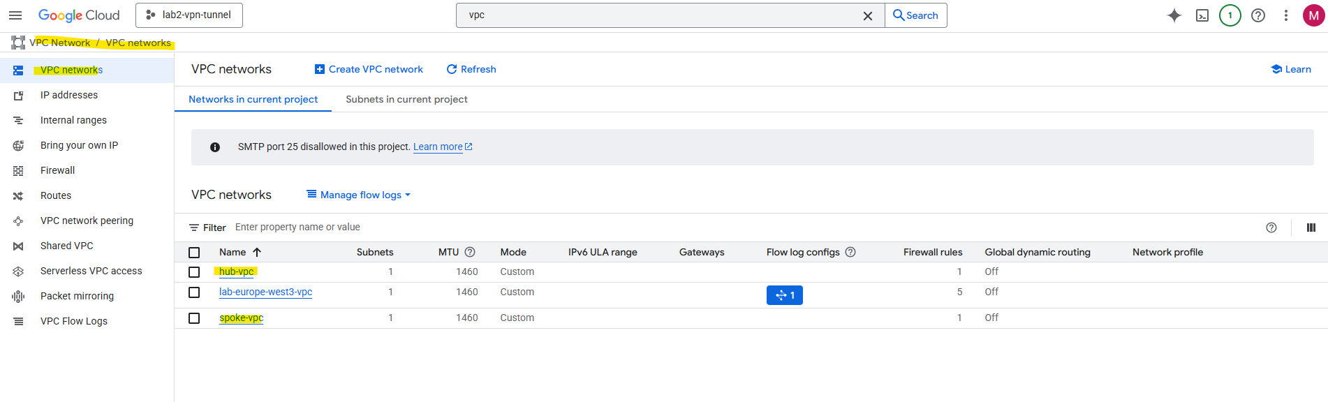
So finally I will have created a hub-and-spoke architecture in the Network Connectivity Center.
Network Connectivity Center (NCC) Hub is the central, global management resource in GCP. It doesn’t carry traffic itself; it holds the routing policy (the “rulebook”) and coordinates connections.
Hub VPC is the actual VPC Network that acts as your central services or transit network.
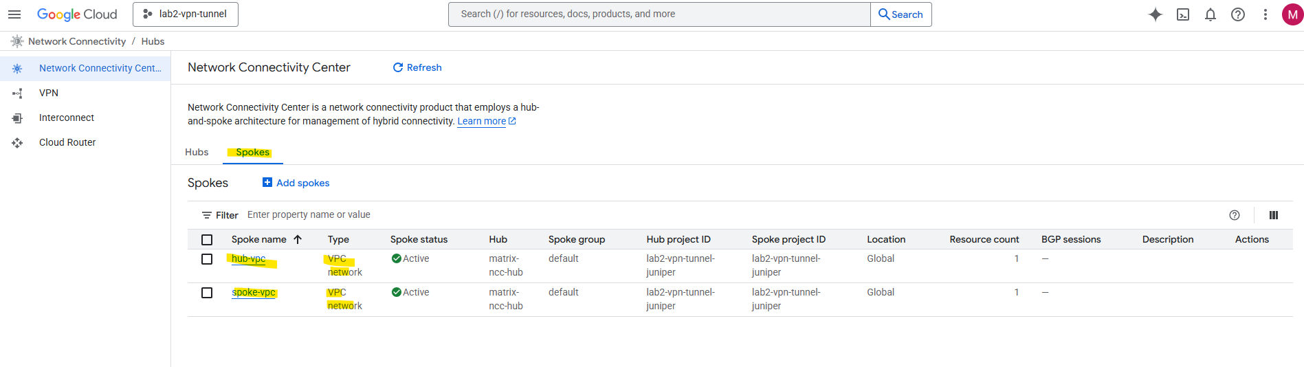
For VPC-to-VPC connectivity via NCC, every single VPC network that needs to communicate (the “Hub VPC” and all “Spoke VPCs”) must be added to the NCC Hub resource as a VPC Spoke.
So also our Hub-VPC need to be added as VPC Spoke in the NCC for cross-VPC routing.
Don’t be confused by the name; the Hub VPC must be explicitly added as a VPC Network Spoke to the Network Connectivity Center (NCC) Hub resource. The NCC Hub is just the control plane, and it won’t automatically route to your central VPC unless that VPC is linked as a Spoke. Failing to do this is a common error that prevents route exchange and causes traffic to incorrectly exit to the internet.
The routes will be propagated automatically.
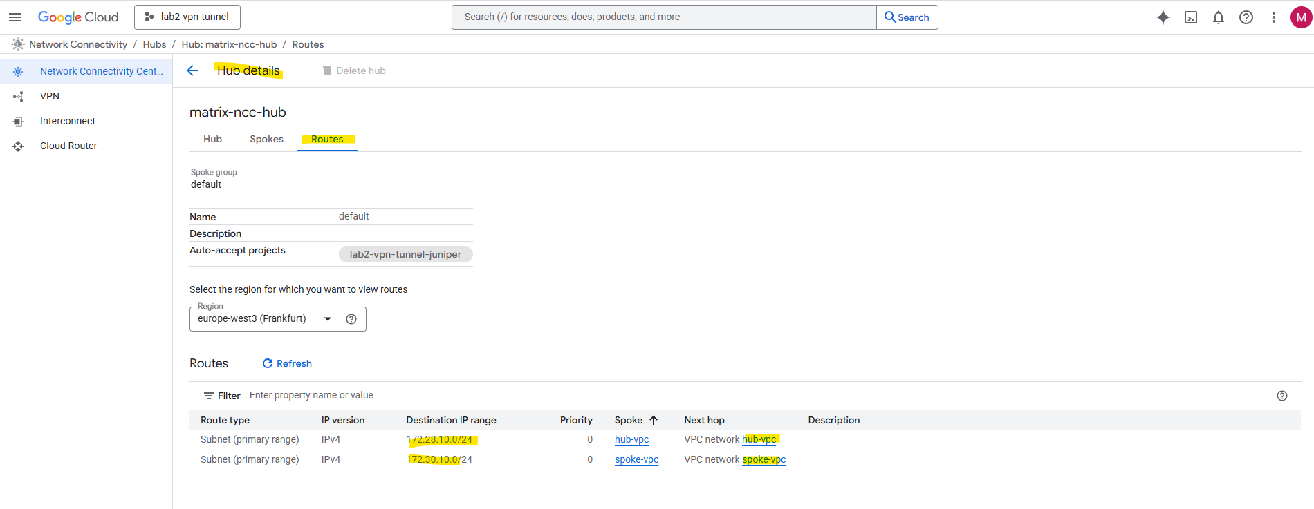
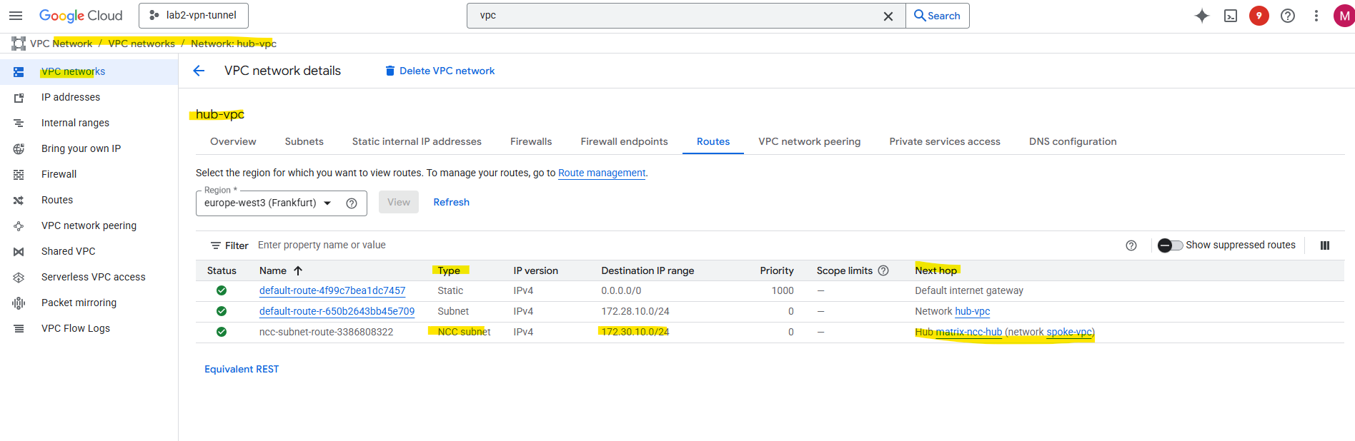
The routes which will be propagated by NCC automatically we will also see directly on the VPC network within the Routes tab as shown below for the Hub VPC network, here we see the route to the Spoke VPC network.
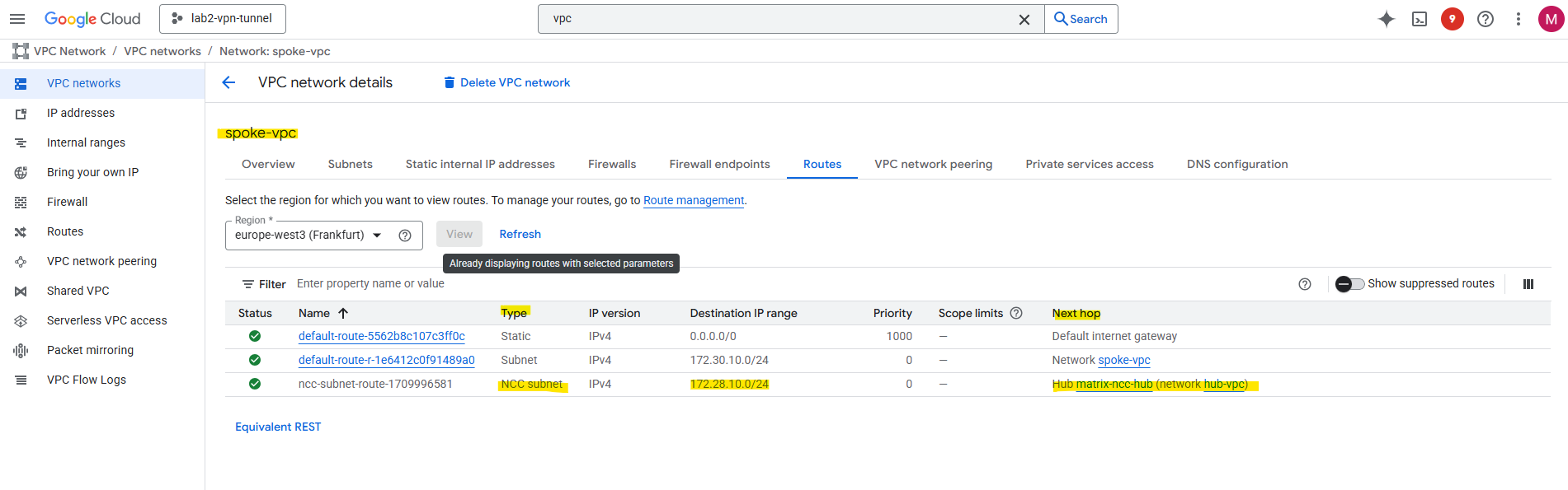
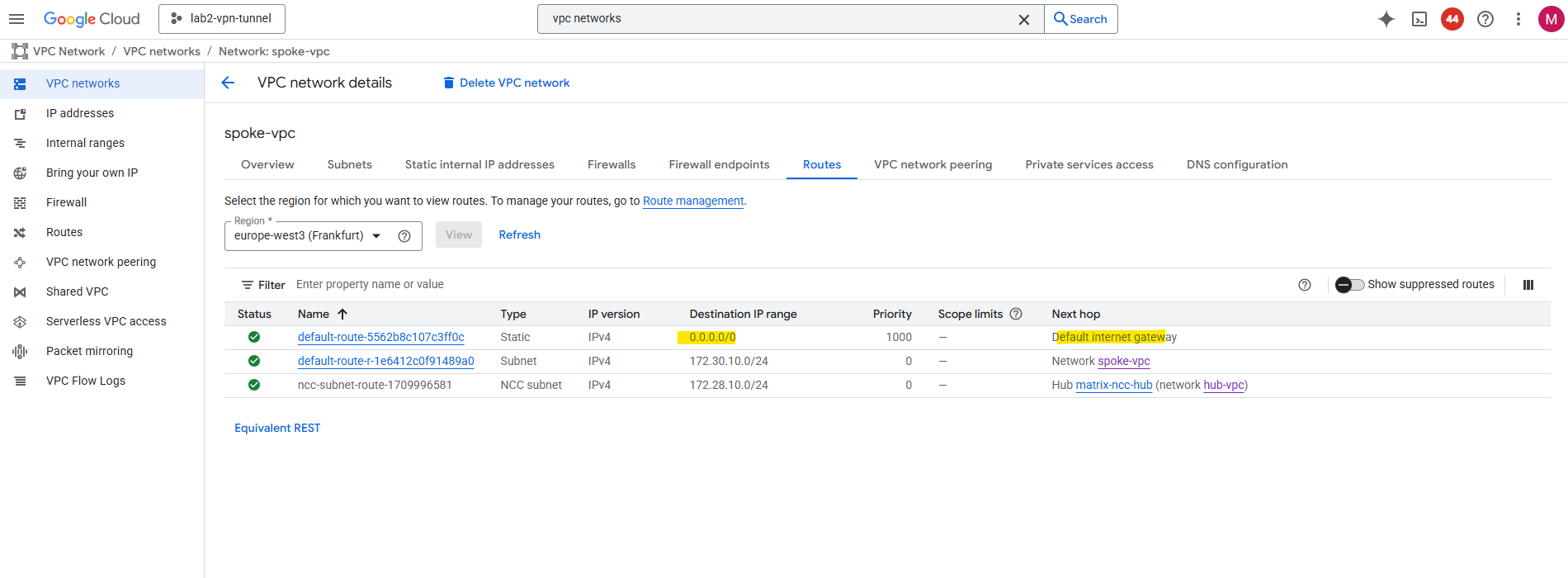
For the Spoke VPC network, here we see the route to the Hub VPC network.
By the way, when viewing the available routes for a VPC network, we also need to select a region. Though the VPC network itself is a global resource, its subnets (IP address ranges) are tied to a specific region.
A VPC network in Google Cloud is like a globally accessible virtual network that spans all Google Cloud regions. However, the fundamental building blocks of a VPC, the IP address ranges that your VMs and other resources actually use, are tied to a region.
The region selection during VPC creation is primarily to define the location and IP range for the initial regional subnet that makes the network usable for your deployed compute resources.
From now on traffic between both VPC networks added as spokes in the NCC Hub, will be routed successfully if allowed by the firewall rules in both VPCs.
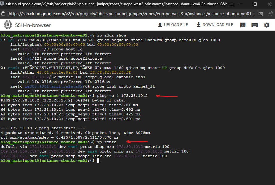
I am able to already ping a VM instance running in the Hub VPC network initiated from a VM instance running in the Spoke VPC network.
The routes propagated by the Network Connectivity Center (NCC) are subnet-level routes, not host-level routes.
NCC propagates the CIDR range of the subnet where the destination VM resides. These routes are automatically installed into the VPC Network’s routing table.
When you run the ip route command inside your Linux VM in the spoke VPC, you are looking at the kernel routing table of that individual instance. You will not see an explicit route for the destination VPC’s subnet installed by NCC. This is by design.
Deploy a NGFW appliance
We can now deploy the NGFW appliance from the GCP Marketplace into your hub VPC (in a dedicated inspection subnet).
For my lab environment I will use currently GCP credits and therefore I will just spin up a standard Linux VM (Ubuntu) and configure it as a simple NAT gateway, proxy or firewall manually.
About how to use instead pfSense and also without additional costs, you can read my following post.
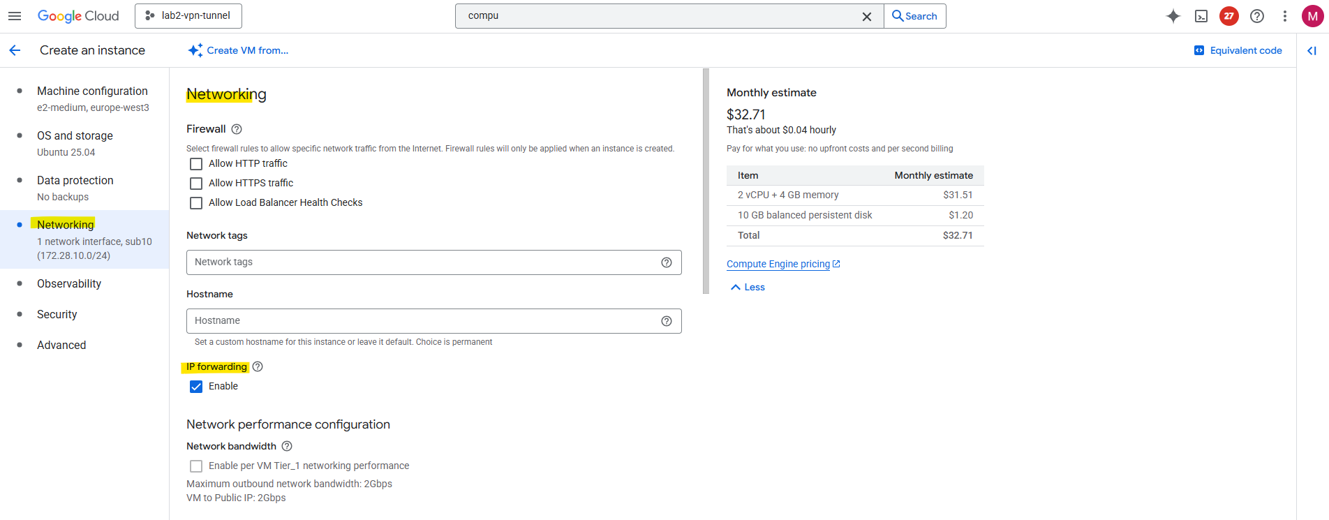
The standard Linux VM (Ubuntu VM instance) I will create in the hub VPC network and dedicated subnet.
On the Networking tab I will have to enable IP forwarding to act as a router.
When you enable “IP forwarding” in the GCP console under the Networking tab during VM creation, that setting only affects the Google Cloud network layer, not the Linux kernel itself inside your VM.
Allows GCP’s virtual network layer to deliver packets not destined for the VM itself, i.e., it can act as a router or NAT gateway. Without this, Google Cloud silently drops any transit packets.
So later we also need to enable IP forwarding directly on the VM.
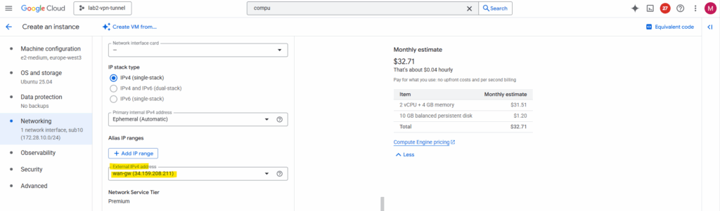
I will also add a static public IP address to the network interface.
Outbound internet traffic works already on the VM I want to use here as workaround for a NGFW appliance.
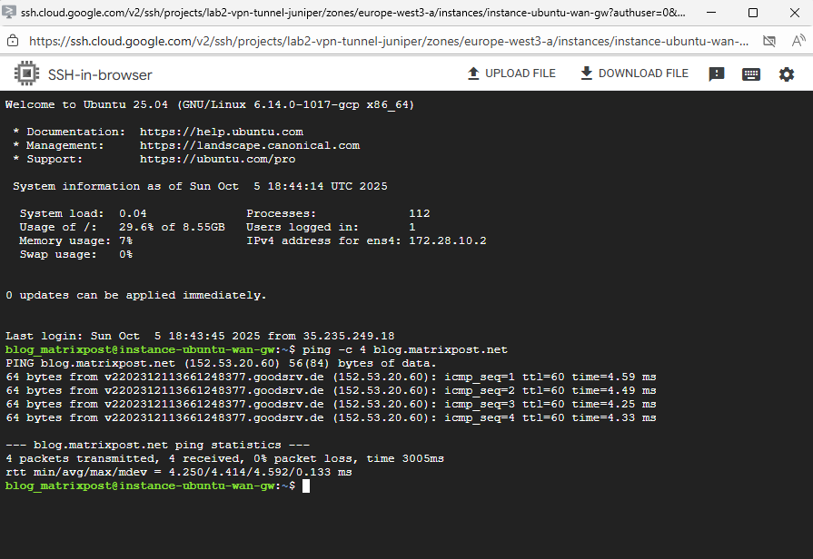
So far IP forwarding is not enabled directly on the OS.
$ sysctl net.ipv4.ip_forward
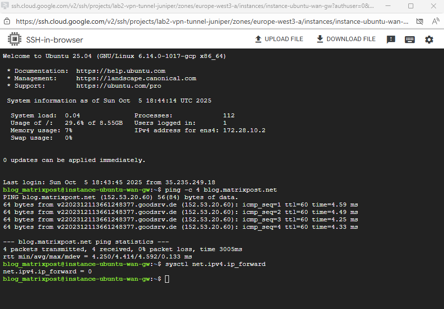
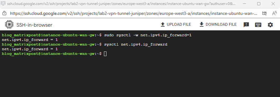
To enable run.
$ sudo sysctl -w net.ipv4.ip_forward=1
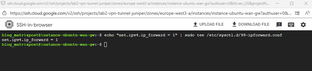
To make net.ipv4.ip_forward=1 finally persistent on our GCP VM, we can run:
$ echo "net.ipv4.ip_forward = 1" | sudo tee /etc/sysctl.d/99-ipforward.conf
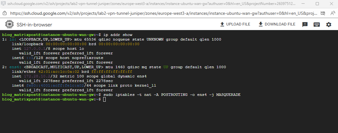
We also need to NAT the internal NIC.
Because the firewall VM only has an internal interface, we need to apply NAT (MASQUERADE) on that interface so that all traffic coming from the spoke networks appears to originate from the firewall’s own internal IP address.
This allows return traffic from the internet to be routed back correctly through the same firewall VM, even though it sits behind Google’s VPC fabric where external IP translation happens outside the guest.
# iptables -t nat -A POSTROUTING -o <internal NIC/interface> -j MASQUERADE
# iptables -t nat -A POSTROUTING -o ens4 -j MASQUERADE
To also make this persistent run:
$ sudo apt update
$ sudo apt install iptables-persistent -y

During install, it will ask:
Save current IPv4 rules?
Choose Yes (and optionally for IPv6).

If rebooted since we added the masquerading rule, execute it again
# iptables -t nat -A POSTROUTING -o <internal NIC/interface> -j MASQUERADE
# iptables -t nat -A POSTROUTING -o ens4 -j MASQUERADE

And save it
$ sudo netfilter-persistent save
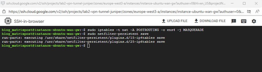
Once both are set, our Ubuntu instance can act as a gateway, proxy, NAT or firewall appliance.
In production environments, instead of using a single-NIC Linux VM, you typically deploy a Next-Generation Firewall (NGFW) appliance such as Fortinet or Check Point with two NICs spread across two separate VPCs, a trusted and an untrusted one.
Both of these VPCs usually act as Hub VPCs in a Network Connectivity Center (NCC) topology, where the trusted side connects to internal spokes and the untrusted side handles outbound Internet or cross-hub traffic.
This dual-hub design provides clear separation of trust zones, centralized policy enforcement, and seamless route propagation between internal networks and the Internet edge.
Deploying Workload VM in the Spoke VPC Network
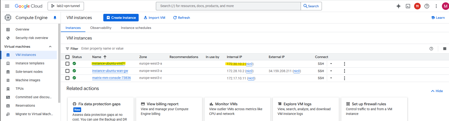
I will now create a workload VM in the spoke VPC network with just a private IP address which later should use the Ubuntu gateway VM.
instance-ubuntu-vm01 with the IP address 172.30.10.2 is running in the spoke VPC network and the gateway is instance-ubuntu-wan-gw with the internal IP 172.28.10.2 running in the hub VPC network.
Deploying an Internal Passthrough Network Load Balancer (ILB)
We cannot directly route traffic from a spoke VPC to the internal IP of an appliance VM running in the hub VPC (or in general different VPC) via VPC Network Peering (or by using the Network Connectivity Center (NCC)).
As long as we not placing a gateway VM/appliance with dual NICs, one in the Spoke VPC and one in the Hub VPC. More about at the end of this post.
To overcome this we can use an Internal Passthrough Network Load Balancer (ILB).
The Internal Passthrough Network Load Balancer (ILB) acting as a next hop is the standard and correct way to overcome this limitation and enable a centralized firewall appliance architecture in a hub and spoke topology.
The ILB provides a single internal IP address in the hub VPC that can be used as a valid next hop in a custom static route. This route can then be exported from the hub VPC and imported by the spoke VPCs via VPC Network Peering.
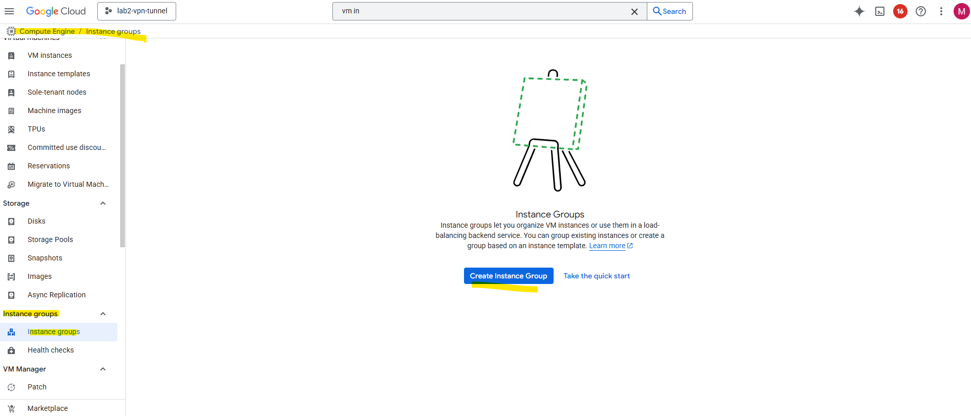
Before we can create a new load balancer, we first need to create a compute engine instance group.
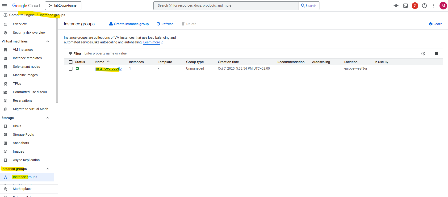
Under Compute Engine browse to Instance groups and click on Create Instance Group.
Instance groups let you organize VM instances or use them in a load-balancing backend service. You can group existing instances or create a group based on an instance template.
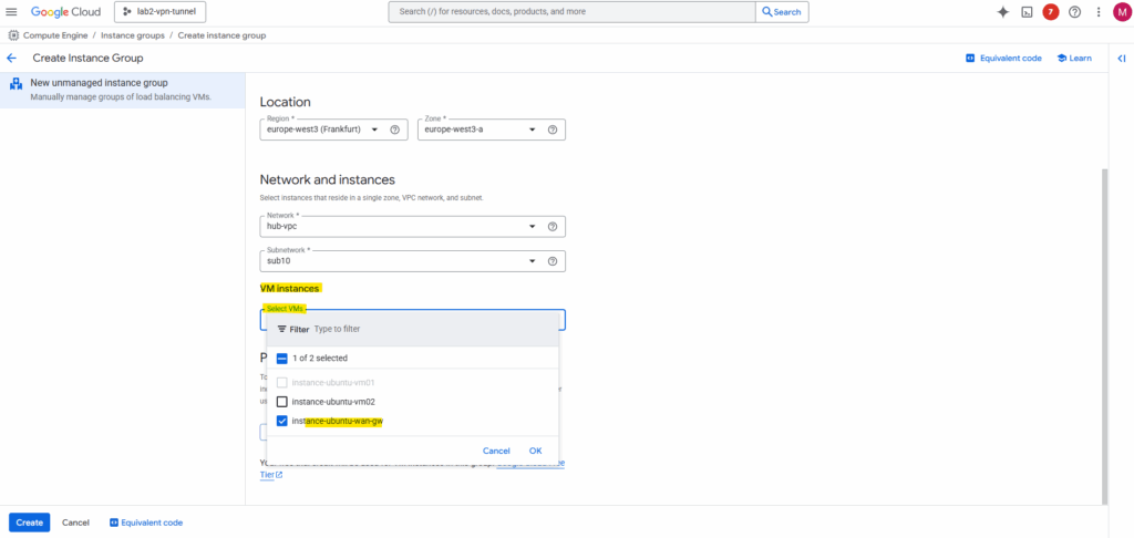
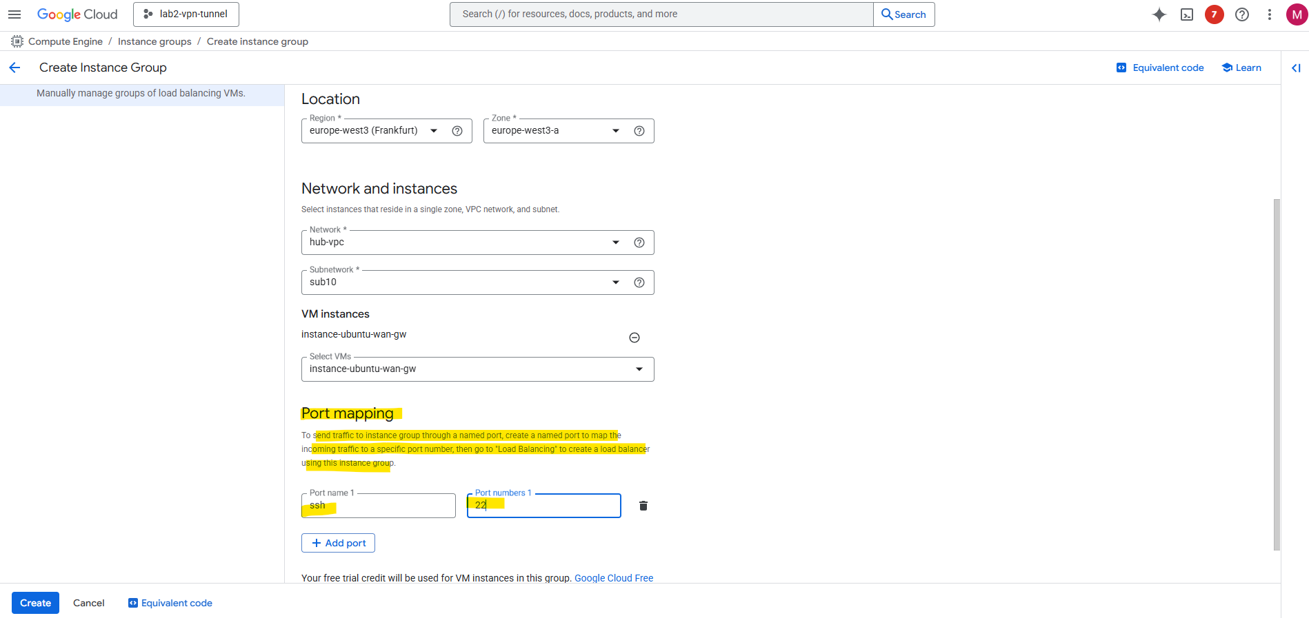
First select on the left menu New unmanaged instance group. Enter a name, the location, network (Hub VPC network) and subnet (our Ubuntu GW VM is running).
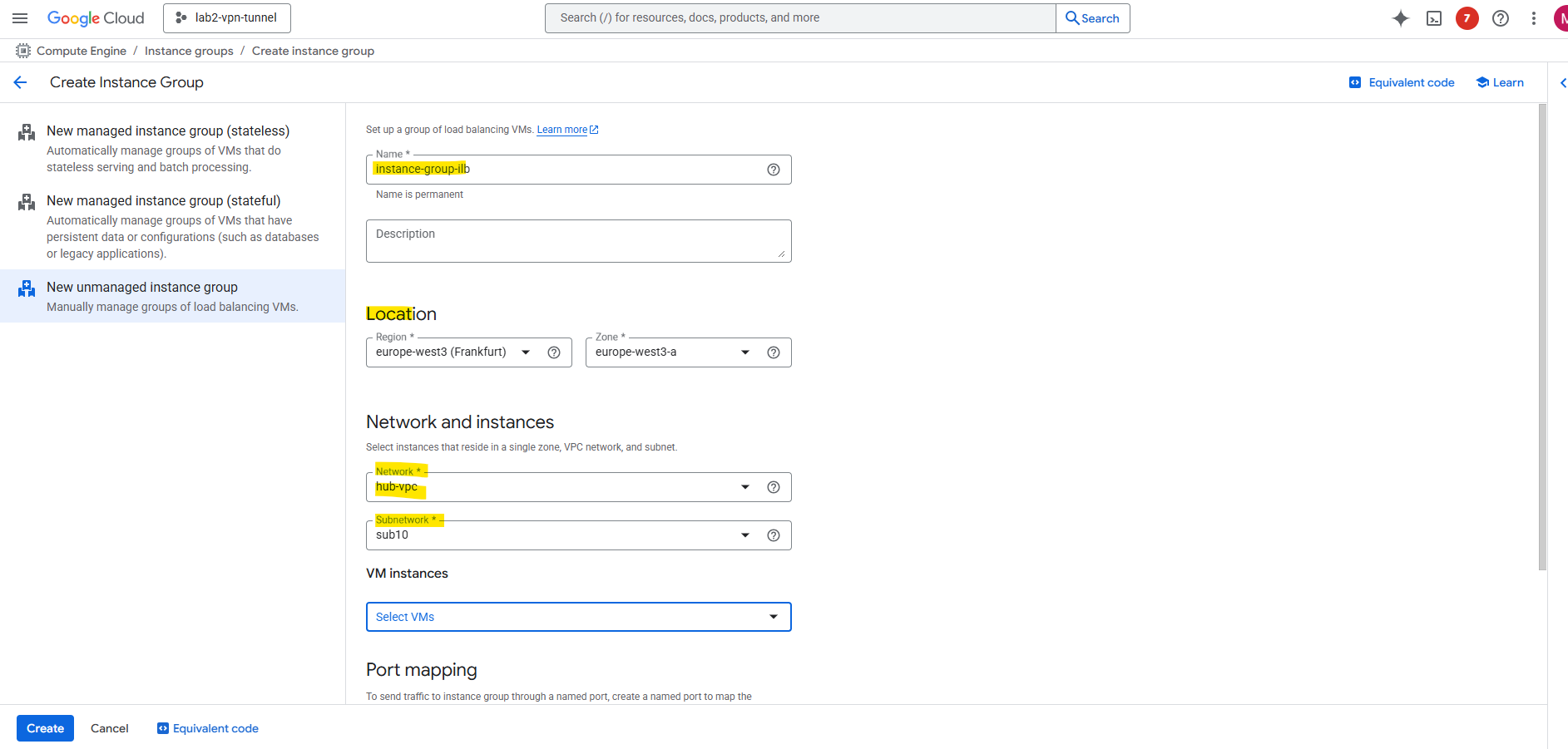
Under VM instances select the Ubuntu GW VM.
Click on Add Port to create a named port. I will use the SSH Port 22. Then click on Create.
Now we can create the load balancer.
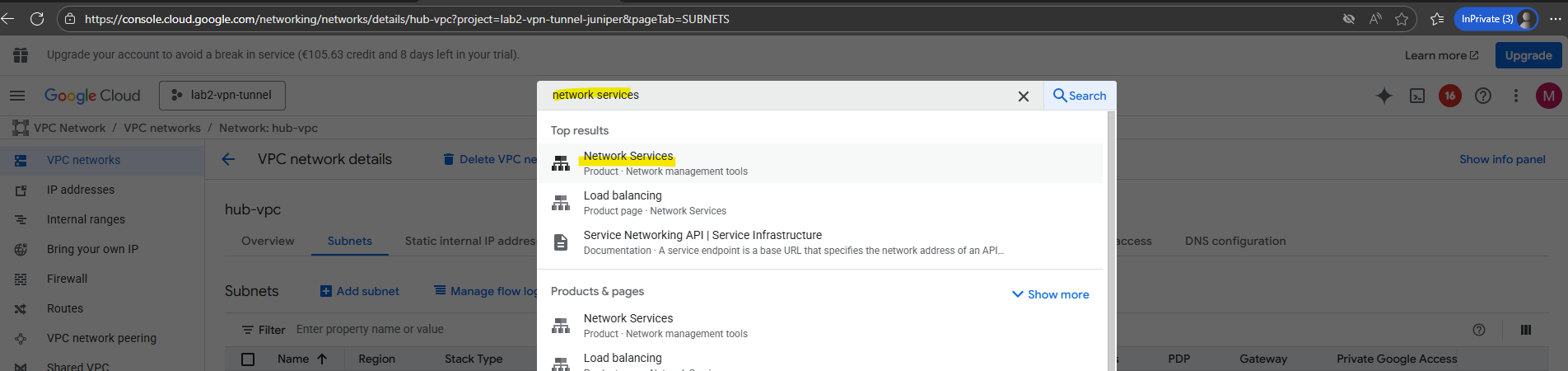
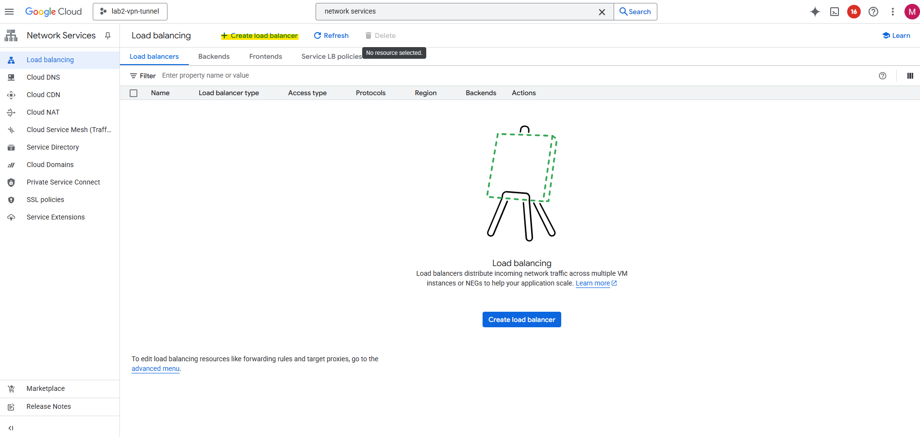
Search for and select Network Services.
Click on + Create load balancer.
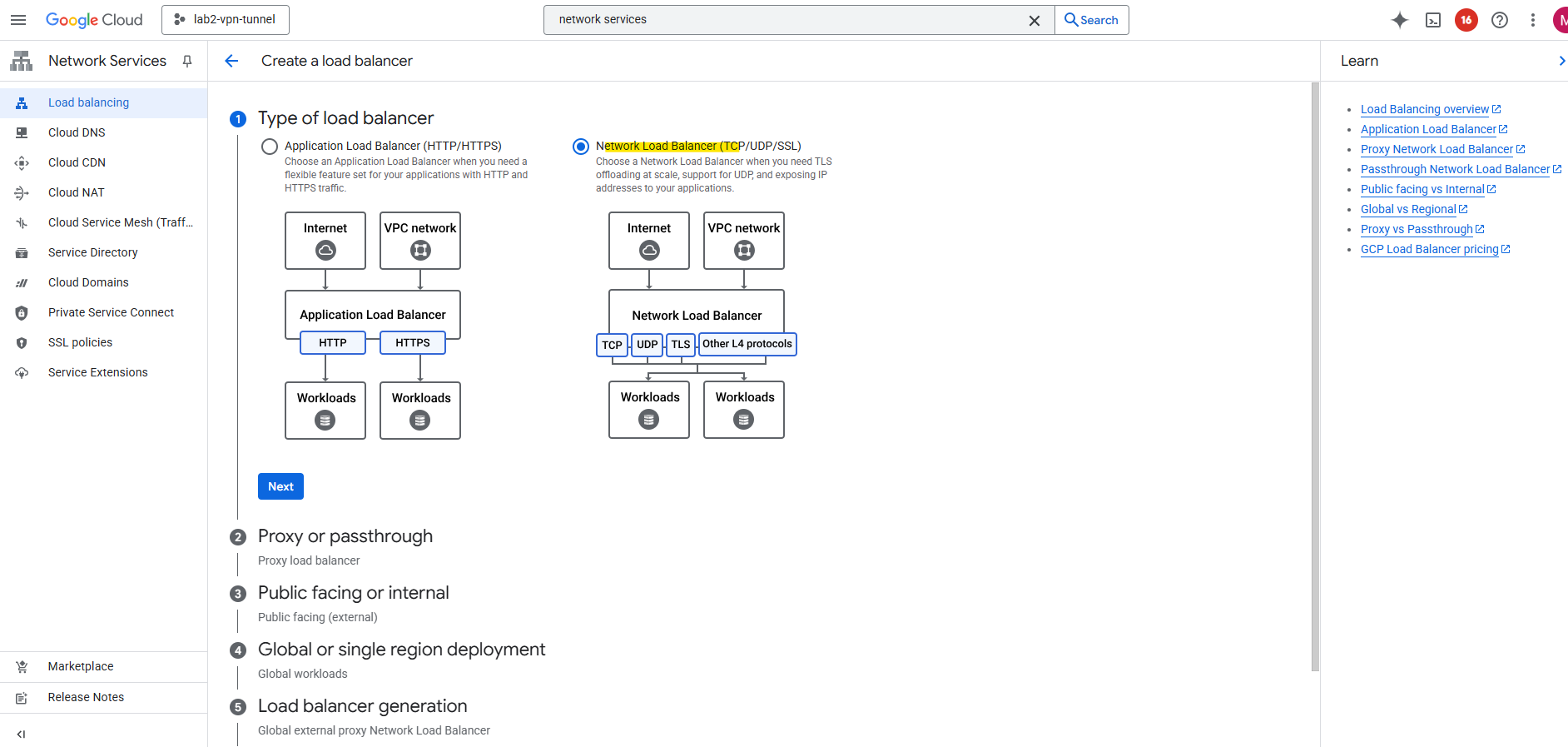
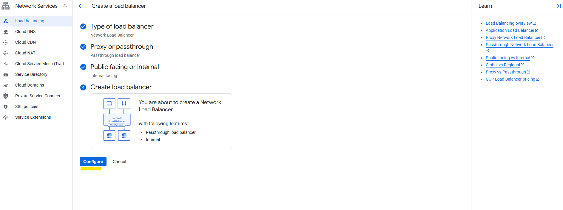
Select Network Load Balancer (TCP/UDP/SSL) and click on Next.
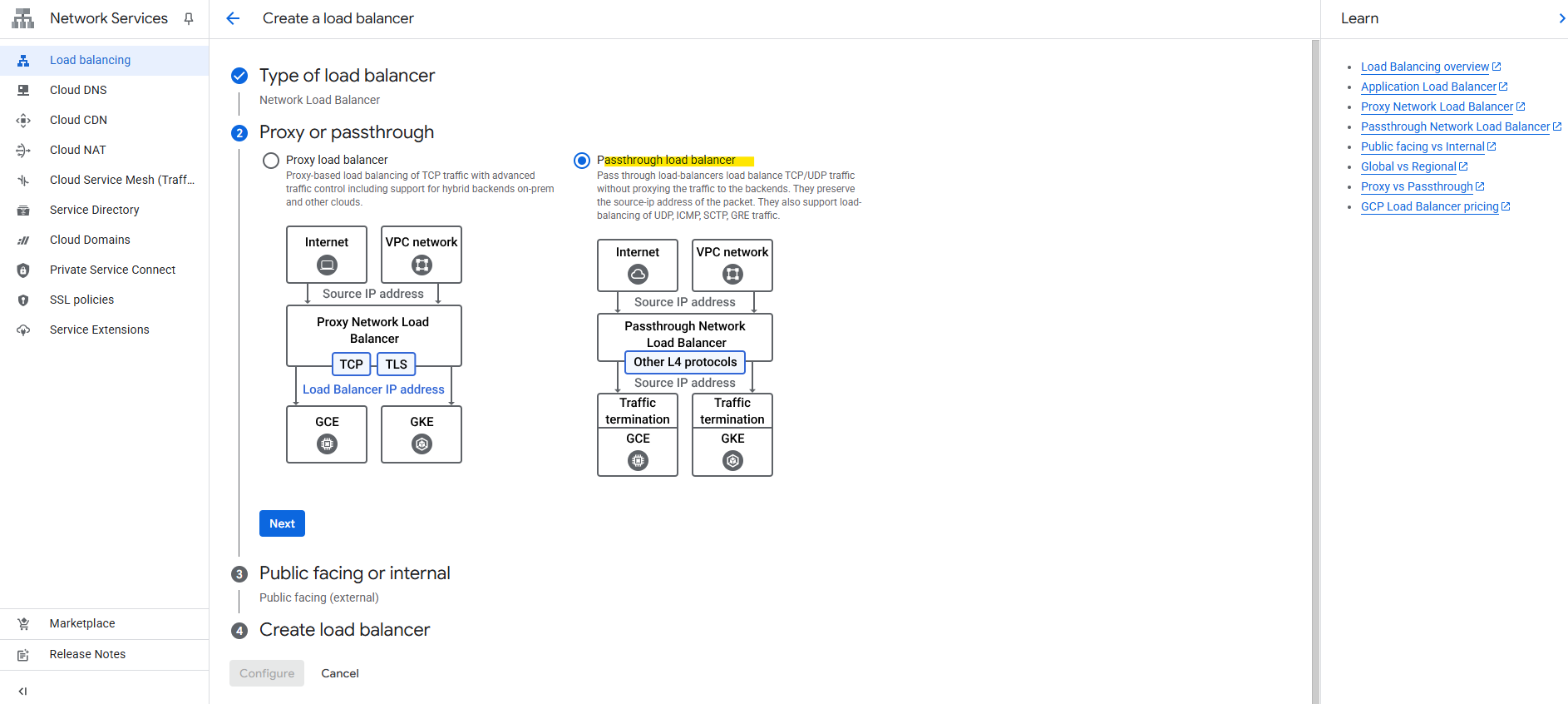
Select Passthrough load balancer.
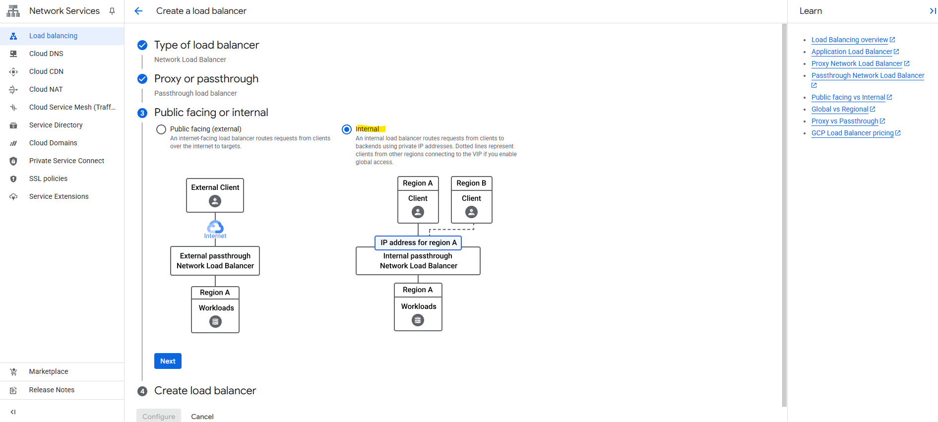
Select Internal and click on Next.
Click on Configure.
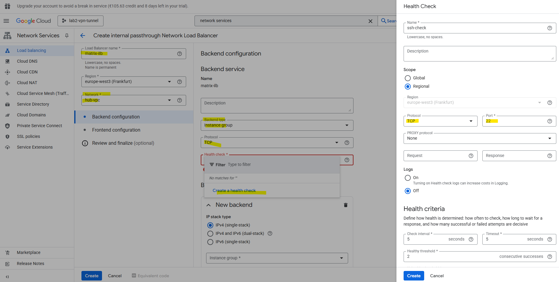
Enter a name for the load balancer, the network, we need to select our hub VPC network where our Ubuntu GW is running, clicking on Create a health check below and select TCP port 22 for SSH.
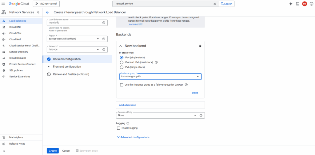
For the new backend select our previously created instance group with our Ubuntu VM GW.
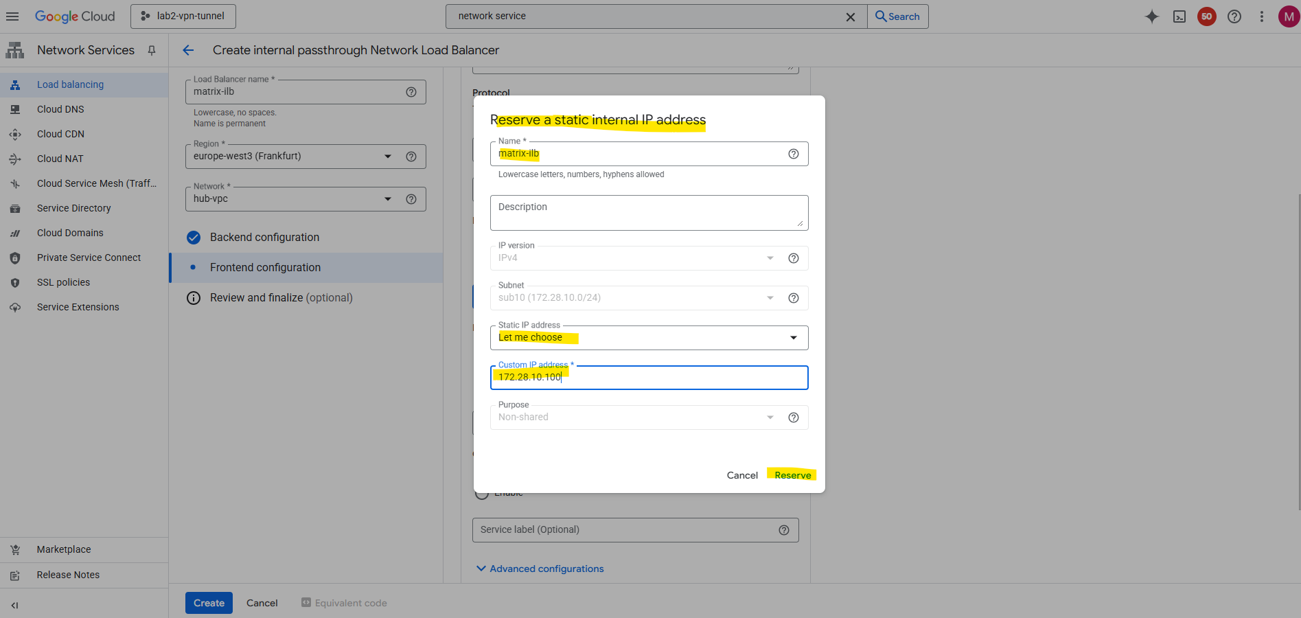
Click on Frontend configuration.

Select the subnet where to place the load balancer to, I will place to the same as my Ubuntu VM GW is running. Also create a new custom IP address for the load balancer.
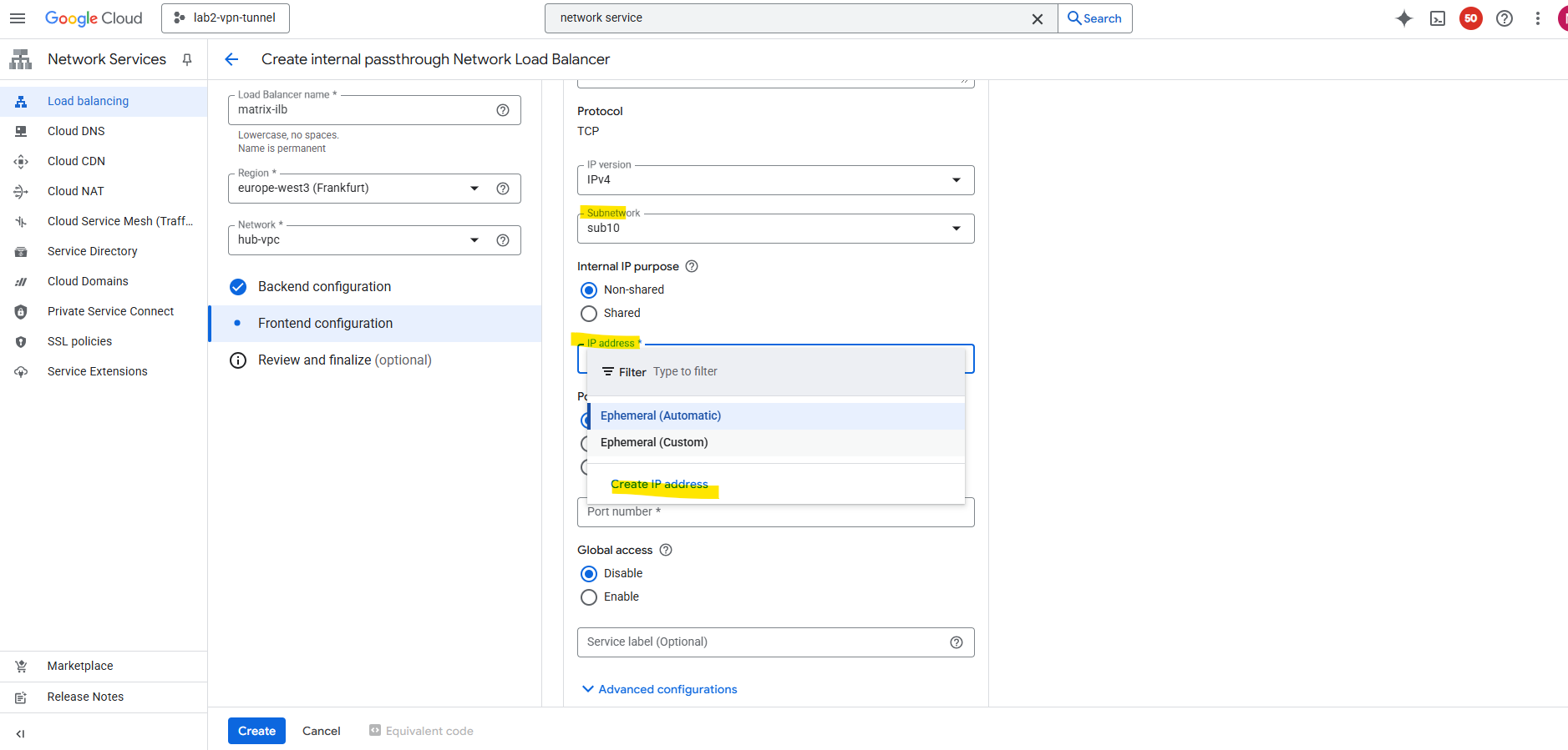
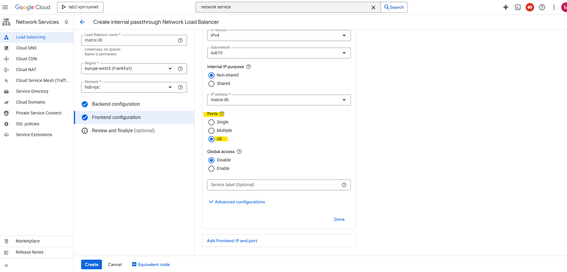
For the forwarding rule select for the Ports below All.
The ILB will forward all TCP and UDP traffic (on any port) it receives on its frontend IP to the backend instance group.
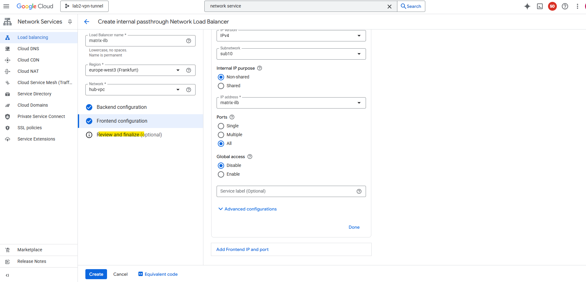
Select Review and finalize or click directly on Create.
Finally click on Create.
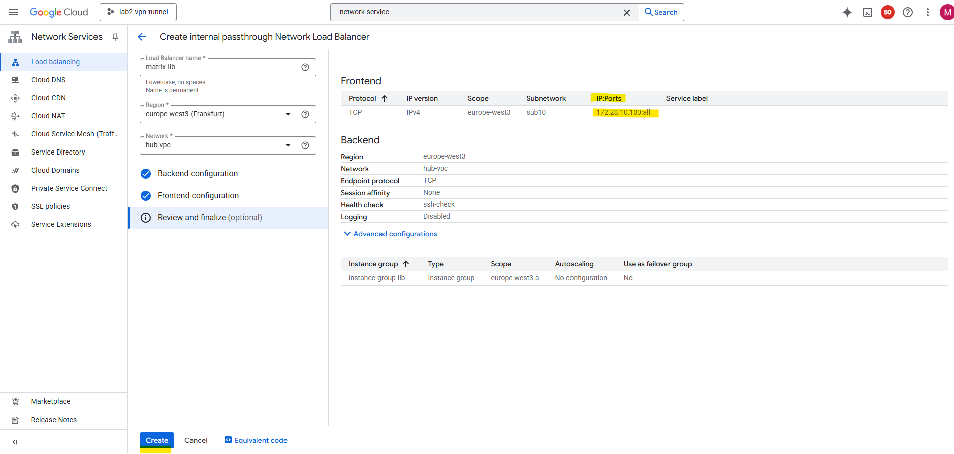
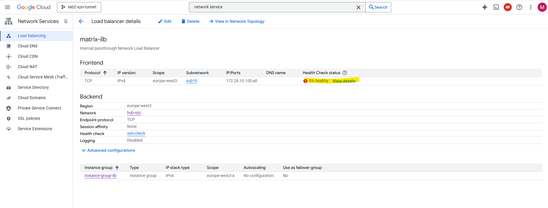
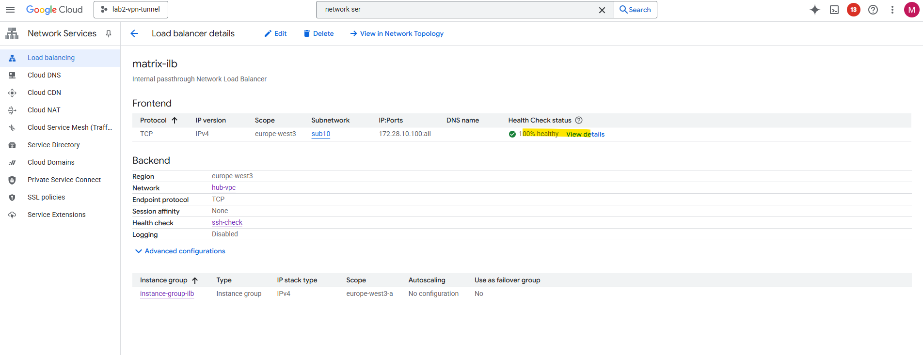
The ILB was created successfully.
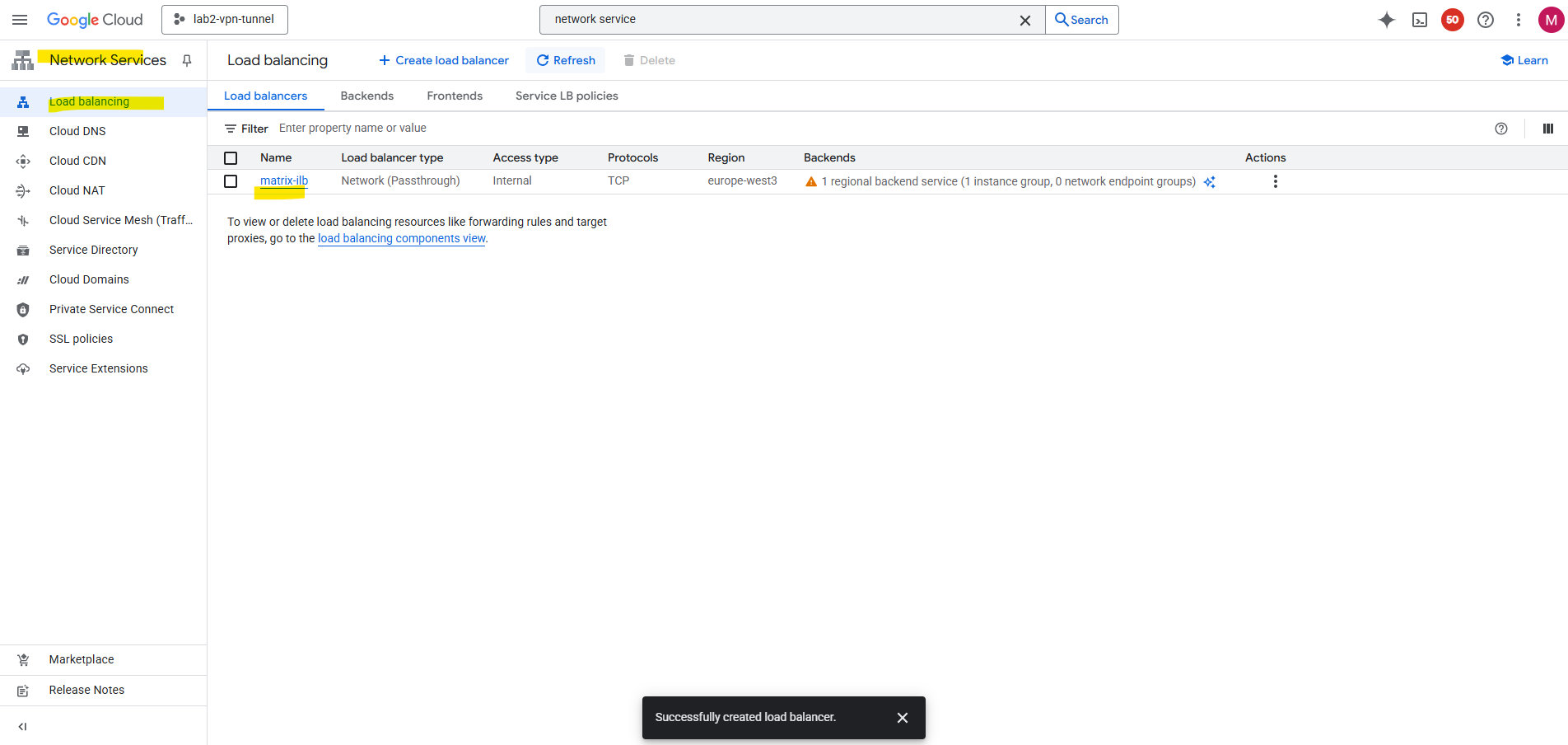
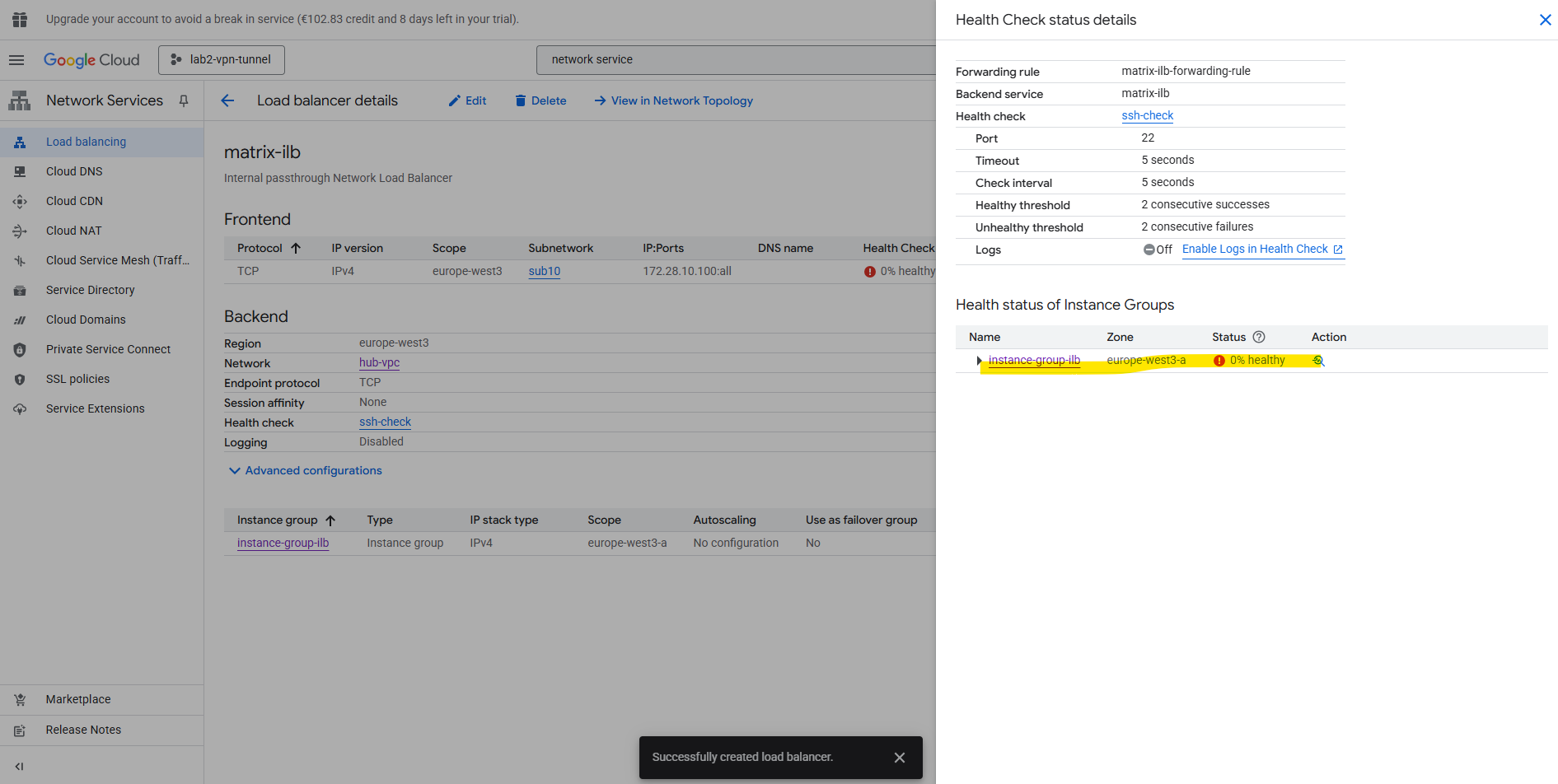
So far the health check (testing to access TCP port 22 on my Ubuntu VM GW’s internal private IP 172.28.10.2) is showing a failure.
So far I just enabled SSH TCP port 22 access in the Hub VPC network for the IAP SSH Proxy shown in Part 2.
The ILB health checks do not originate from the ILB’s frontend IP (172.28.10.100) or our subnet’s range.
Instead, they come from Google’s internal health checkers, which use special, reserved IP ranges.For each region, Google publishes the source IP ranges for these probes here https://cloud.google.com/load-balancing/docs/health-check-concepts#ip-ranges.
Internal passthrough Network Load Balancer ==> 35.191.0.0/16 + 130.211.0.0/22
For health checks to work, we must create ingress allow firewall rules so that traffic from Google Cloud probers can connect to our backends.
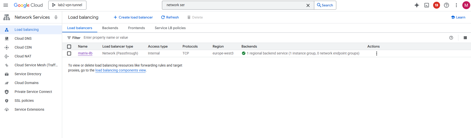
After adding both Google Cloud probers source IP ranges (35.191.0.0/16 + 130.211.0.0/22) to my SSH Port 22 ingress allow firewall rule, the health check switches to green healty.
Create a Custom Route (new Default Internet Gateway) in the Spoke VPC
Next we need to create a custom route in the Spoke VPC to route traffic to the internet (default gateway 0.0.0.0/0) directly to our Internal Passthrough Network Load Balancer (ILB) and its frontend IP.
So far just the default internet gateway assigned by Google Cloud is available.
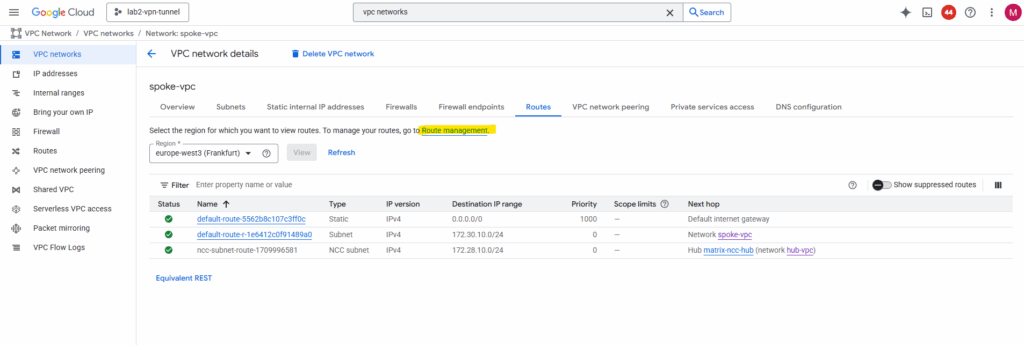
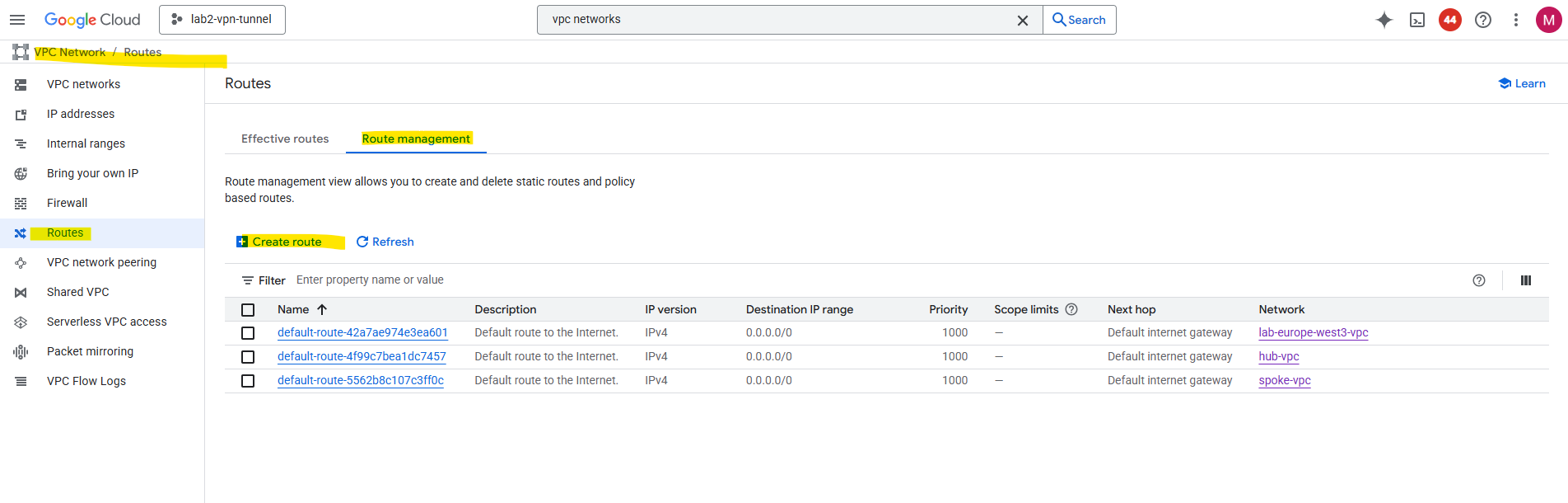
Click on Route management.
Click on + Create route.
For the network select the Spoke VPC, for the destination enter 0.0.0.0/0, the priority should be lower then the default internet gateway assigned by Google Cloud.
For the Next Hop (type) select Specify a forwarding rule IP address of internal passthrough Network Load Balancer and in the Forwarding rule IP address enter the ILBs frontend IP.
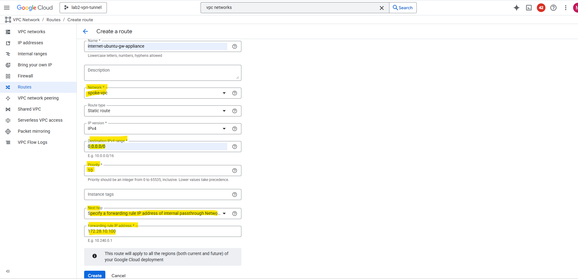
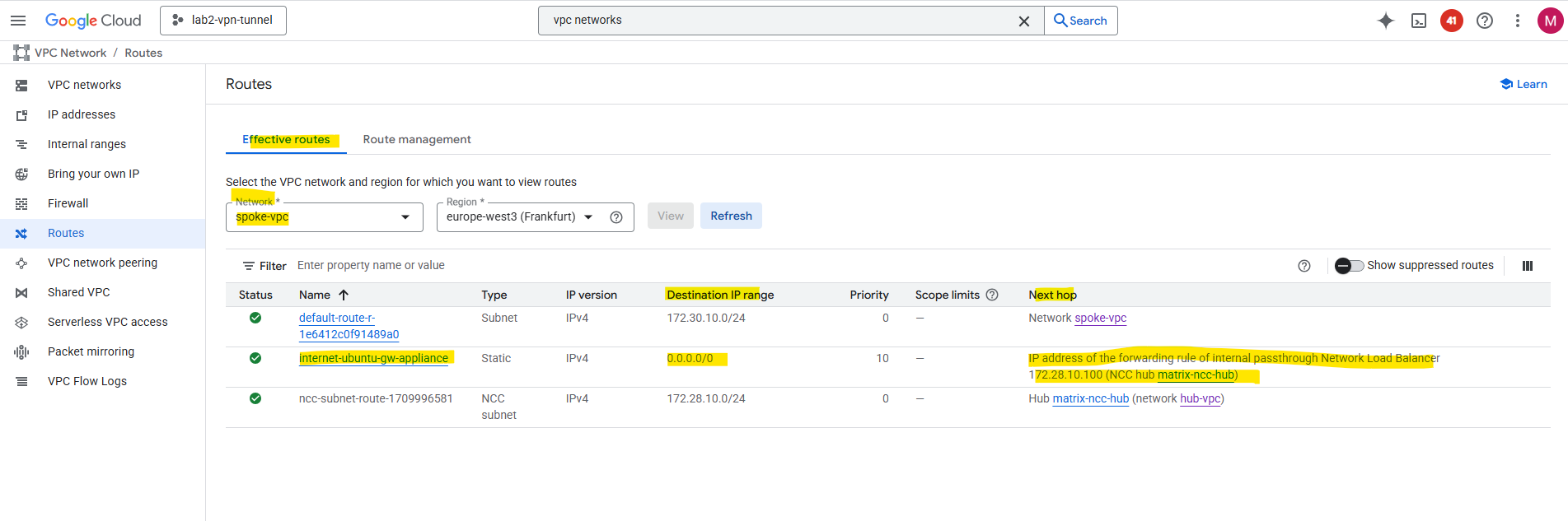
The new custom route is created successfully.
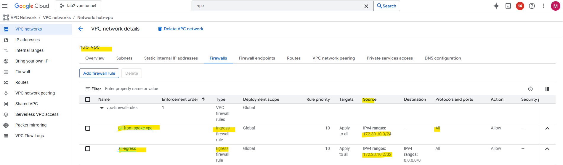
Finally we also need to allow traffic from spokes to reach the ILB and firewall VM. Therefore we need to configure the following firewall rules in the Hub VPC.
| Direction | Action | Source | Target | Protocol/Ports |
|---|---|---|---|---|
| Ingress | Allow | 172.30.10.0/24 (spoke CIDRs) | fw-vm / hub-vpc | All (or TCP/UDP as needed) |
| Egress | Allow | fw-vm → Internet | 0.0.0.0/0 | All |
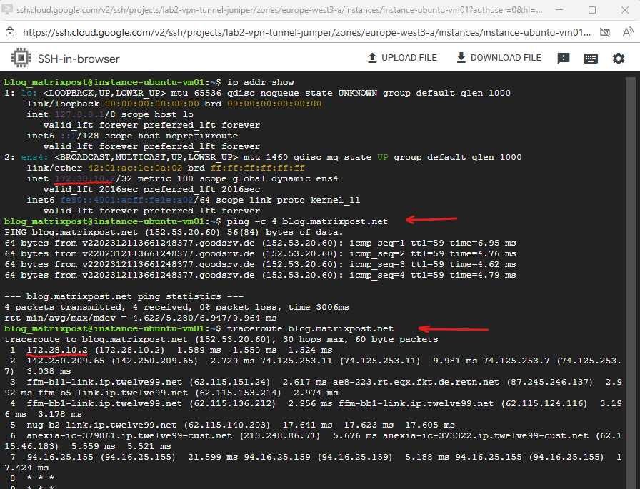
Final check for outbound internet traffic initiated from an VM instance running in the Spoke VPC.
We can see that outbound internet traffic is routed through the IP address 172.28.10.2 which is our Ubuntu gateway VM (appliance).
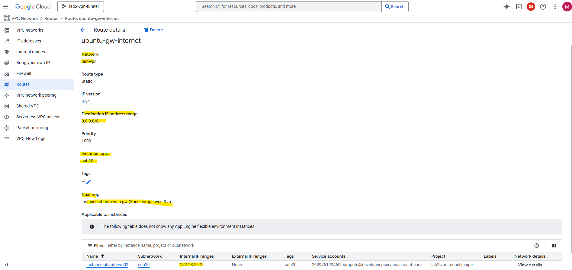
Create a Custom Route (new Default Internet Gateway) in the Hub VPC itself
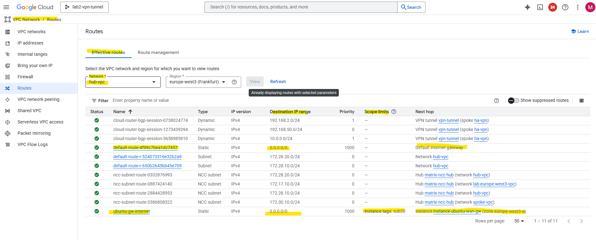
To route outbound internet traffic from the hub-VPC itself through the same gateway appliance, a custom route for 0.0.0.0/0 can be created with the next hop set to the internal IP address of the Ubuntu gateway.
To avoid a routing loop (which would break the gateway’s own internet connectivity), the route is scoped using an instance network tag, or example, sub20.
This way, only VMs in the hub-VPC that have the tag sub20 applied will use the custom route for their default traffic, while the gateway VM itself is excluded and continues to use the VPC’s default internet gateway for its own outbound connections.
VM instances with a public IP (here our gateway VM) always egress through Google’s default internet gateway, their traffic is NATed by the VPC fabric to the external IP and not routed through internal gateways or custom routes.
When the custom route 0.0.0.0/0 with the next hop set to our Ubuntu gateway VM (NGFW appliance in production) is applied to the gateway’s own “total” subnet, the gateway VMs outbound traffic to the internet is also routed back to itself via that same route.
This causes the gateway to repeatedly send its own packets to its own next hop (itself), never reaching the VPC’s default gateway. In other words, the gateway becomes its own next hop for all traffic, creating an internal routing loop.
This tag-based routing approach is a clean, cloud-native way to enable centralized egress for selected instances without affecting the gateway’s own reachability.
Final Thoughts about the ILB Option as valid Next Hop
GCP only allows you to route cross-VPC traffic to an ILB next hop (and not directly to a VM’s internal IP in another VPC).
For more flexible or segmented topologies, an alternate architecture places a gateway VM with dual NICs, one in the Spoke VPC and one in the Hub VPC.
In that setup, traffic from the spoke can go directly into the gateway VM, be inspected or NAT’d, and then forwarded from its Hub-facing interface toward the Internet or NCC transit.
This configuration can help reduce hop counts, simplify routing, or offload hub-side processing (e.g. firewall policies) closer to the spoke edge.
Why this design exists at all?
In Google Cloud, each VPC network is a completely independent, distributed routing domain.
- Every VPC has its own control plane, route tables, and next hop resolution.
- VMs and their internal IPs are only meaningful inside that one VPC’s routing fabric.
- Even if you connect two VPCs (via Peering or NCC), Google doesn’t merge their routing control planes, it just exchanges prefixes, not next-hop relationships.
So from the perspective of the spoke VPC, the firewall VM’s internal IP (e.g., 172.28.10.2 in the hub) doesn’t exist as a routable next hop.
It’s an address inside another routing domain.
An Internal Passthrough Network Load Balancer (ILB) is a special GCP-managed construct that lives at the boundary between the VPCs but is still recognized by the GCP control plane as a valid routing object.
When you create a route like:
0.0.0.0/0 → next hop ILB 172.28.10.100
Google internally resolves that ILB into backend targets (firewall VMs) within the hub using GCP’s global control plane.
So the ILB acts as a “proxy next hop”, it’s a managed endpoint that:
- Exists as a first-class routing object visible across peered or NCC-connected VPCs.
- Knows how to forward traffic internally (Layer-3 passthrough).
- Provides health checks, load balancing, and cross-VPC next-hop abstraction.
This is why it’s valid to reference an ILB IP as a next hop, but not a random VM IP in another VPC.
Links
Cloud NAT overview
https://cloud.google.com/nat/docs/overviewRouter appliance overview
https://cloud.google.com/network-connectivity/docs/network-connectivity-center/concepts/ra-overviewInternal passthrough Network Load Balancer overview
https://cloud.google.com/load-balancing/docs/internalInstance groups
https://cloud.google.com/compute/docs/instance-groupsRoutes
https://cloud.google.com/vpc/docs/routesConfigure Private Google Access
https://cloud.google.com/vpc/docs/configure-private-google-accessCloud VPN overview
https://cloud.google.com/network-connectivity/docs/vpn/concepts/overview