Step-by-Step Guide: Setting Up Juniper vSRX3 Appliance
The Juniper vSRX3 is a virtual firewall appliance that delivers next-generation security services in virtualized and cloud environments.
It runs Juniper’s Junos OS and offers the same rich feature set as physical SRX firewalls, including routing, VPN, firewall policies, NAT, IPS, and advanced threat protection but in a lightweight, virtualized form factor.
Juniper SRX Series Firewalls are an integral part of the Juniper Connected Security portfolio, which protects your network edge, data center network, and cloud applications. Powered by the Junos operating system, the firewalls are available in physical, virtual, and containerized form factors. They’re all managed by Juniper Security Director Cloud for a unified management experience and consistent security policy enforcement across your hybrid network.
SRX Series Firewalls are the industry’s most effective against threats. They offer AI-driven protection, accurately predicting intrusions, malware, and other threats and stopping them before they stop your business.
Source: https://www.juniper.net/us/en/products/security/srx-series.html
Ideal for cloud-native architectures, private data centers, and testing labs, the vSRX3 supports high throughput, scalable multi-tenancy, and is commonly deployed on platforms like VMware, KVM, OpenStack, and public clouds such as AWS, Azure, and GCP.
With its robust API support, fast boot time, and full integration into automation frameworks, vSRX3 is a flexible solution for securing modern hybrid and multi-cloud environments.
In this post we will see step by step the initial setup and network interface assignment, further we will see how to configure the Firewall to allow outbound internet access and how to publish internal services like a web server to Internet.
About how to setup a route-based S2S IPSec Tunnel with Azure by using Juniper as VPN device in on-premise, you can also read my following post.
- Introduction
- Set up Juniper vSRX3 in vSphere
- Configure Appliance
- Configure a Plain-Text Password for Root Logins
- Configure Management Interface (fxp0)
- Enable SSH
- Install the Trial License
- Configure the Data Interfaces (ge-0/0/0 and ge-0/0/1)
- Configure the Name Servers
- Adding a Static Route for outbound Internet Access
- Configure Security Zones and Zone Addresses
- Configure Security Policies
- Configure Host Inbound Traffic on a Security Zone
- Configure NAT
- Monitoring Logs
- Capture Traffic on Fritz!Box
- Links
Introduction
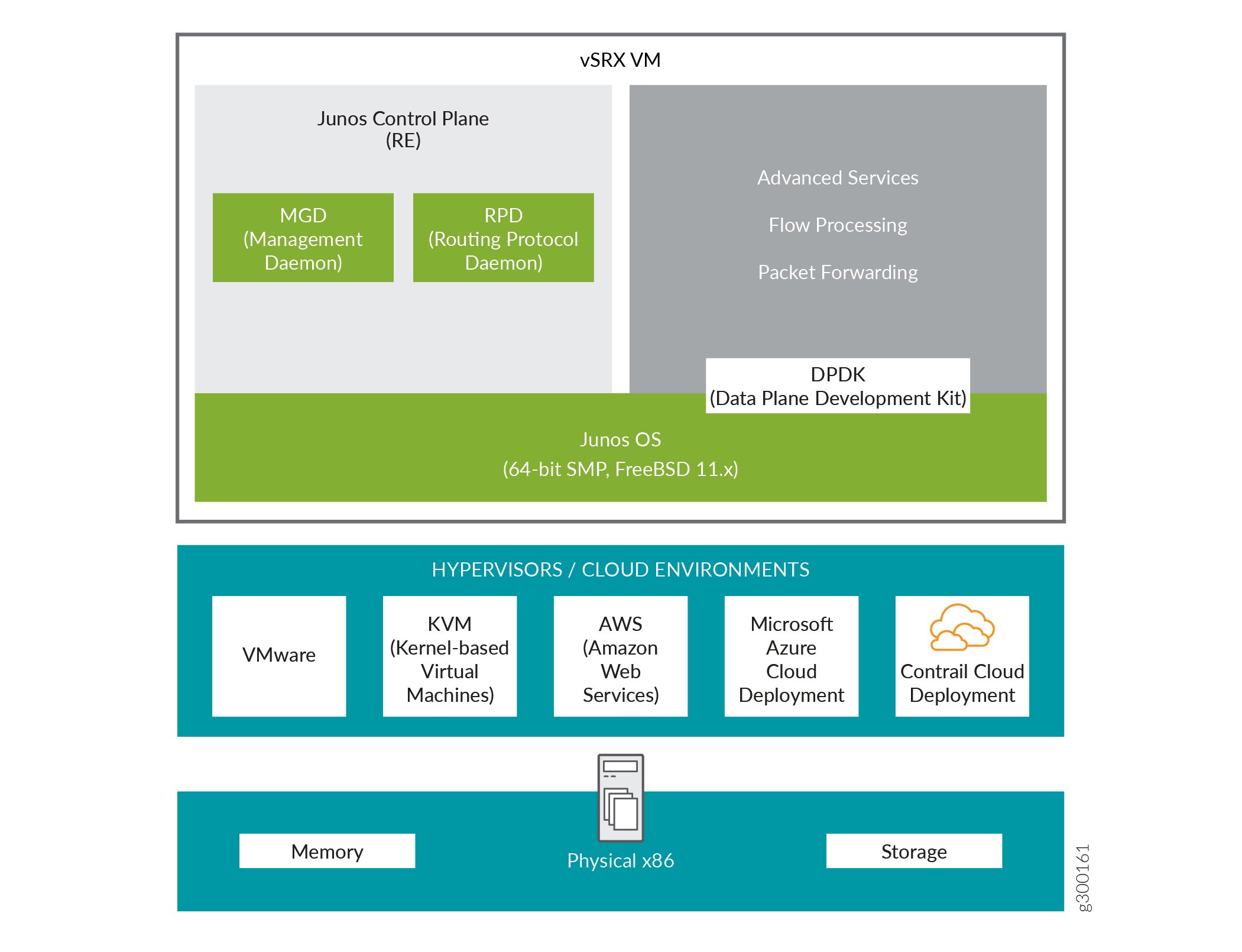
In Junos OS Release 18.4R1, we’ve introduced a new software architecture vSRX3.0 for vSRX Virtual Firewall virtual firewalls. We recommend that you migrate to vSRX3.0 for your vSRX Virtual Firewall VM.
If you are using vSRX2.0, you can migrate to the new vSRX3.0 in few steps. Note that the command-line interface (CLI) remains the same and the configuration that works on vSRX2.0 also works in vSRX3.0.
The new vSRX3.0 architecture is a streamlined virtual machine (VM) using FreeBSD 12.x / Junos OS as operating system.
In vSRX3.0, the Routing Engine and the Packet Forwarding Engine run on FreeBSD 12.x or later version as single VM for improved performance and scalability. The vSRX3.0 uses DPDK to process the data packets in the data plane.
Migrating to vSRX3.0 enables you to quickly introduce new services, deliver customized solutions, and scale security services dynamically due to:
- Faster boot-time and enhanced responsiveness of the control plane during management operations
- Increased operational benefits due to faster commits and CLI upgrades
- Increased agility and smaller image size due to elimination of dual OS and nested virtualization
- No special configuration required for enabling promiscuous mode on the management port and cluster control links
- Simplified and seamless deployments across different host environments
Set up Juniper vSRX3 in vSphere
Below I will go step by step through the installation and configuration process of Juniper vSRX3.
Download the .OVA Appliance
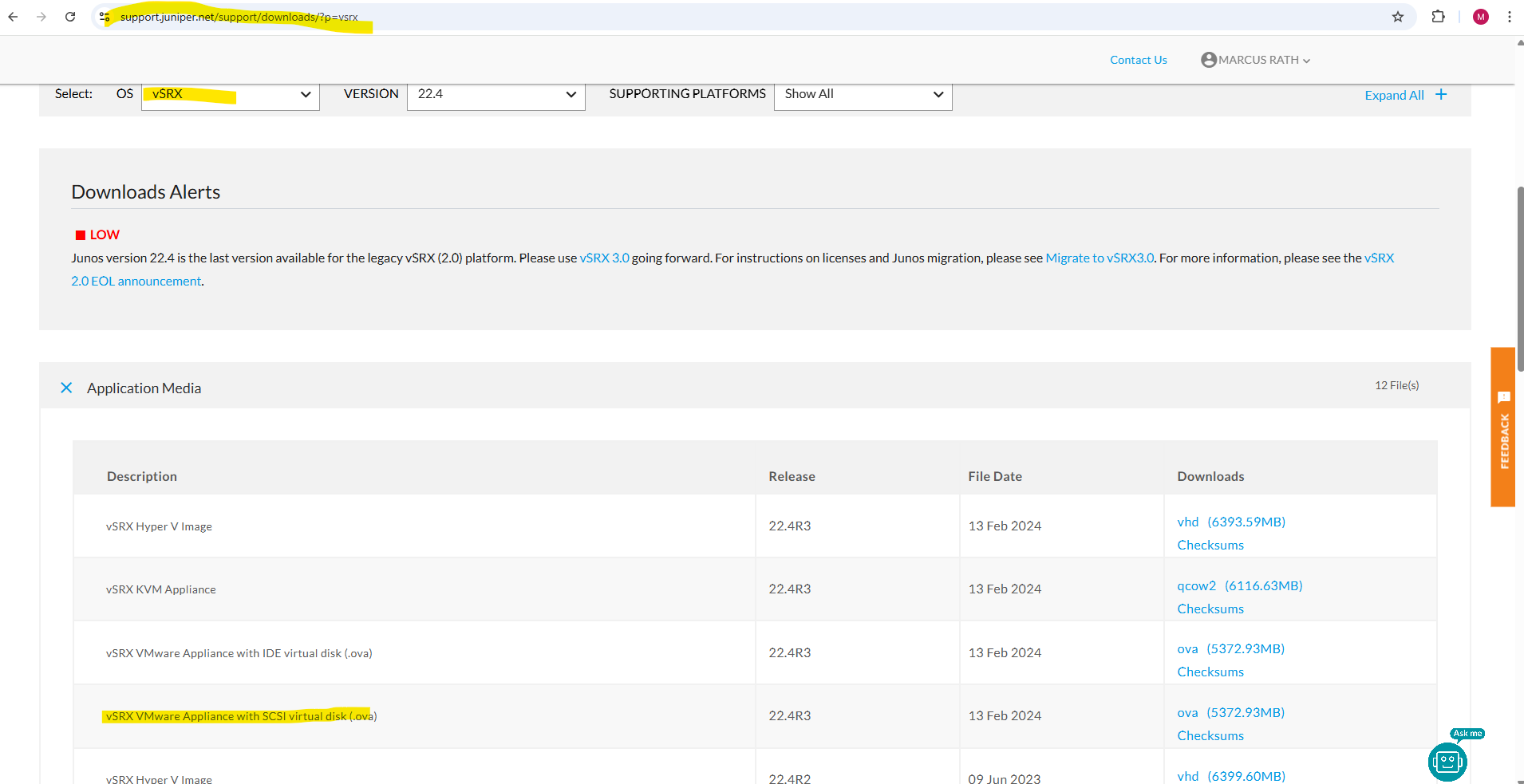
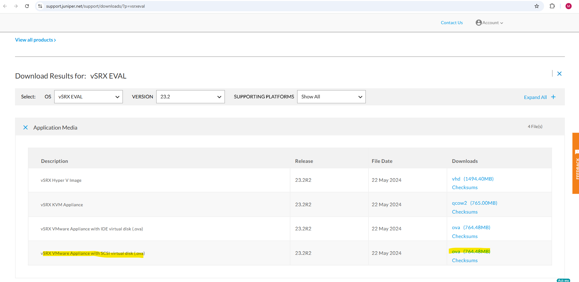
VM-based Juniper appliances you will find here https://support.juniper.net/support/downloads/?p=vsrx.
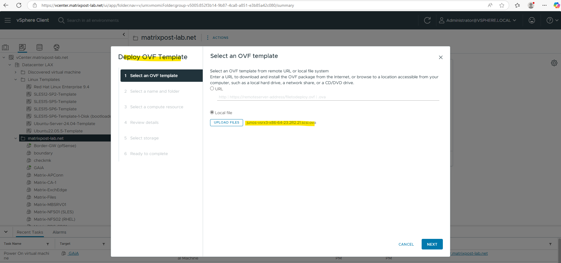
For VMWare vSphere we can use the vSRX VMware Appliance with SCSI virtual disk (.ova).
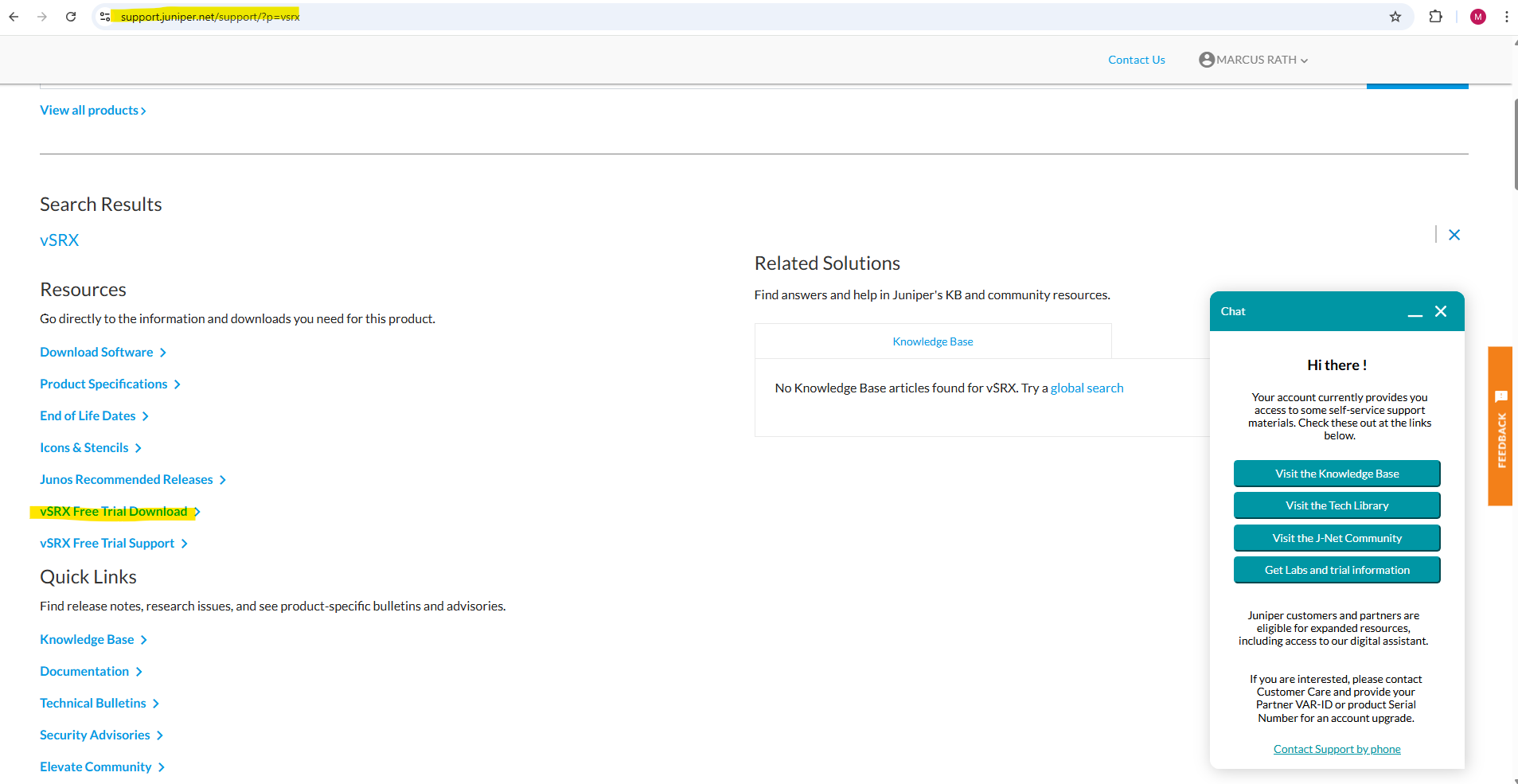
Trial versions we can download under https://support.juniper.net/support/?p=vsrx in case we have already created an account.
I will download the SCSI virtual disk .(ova).
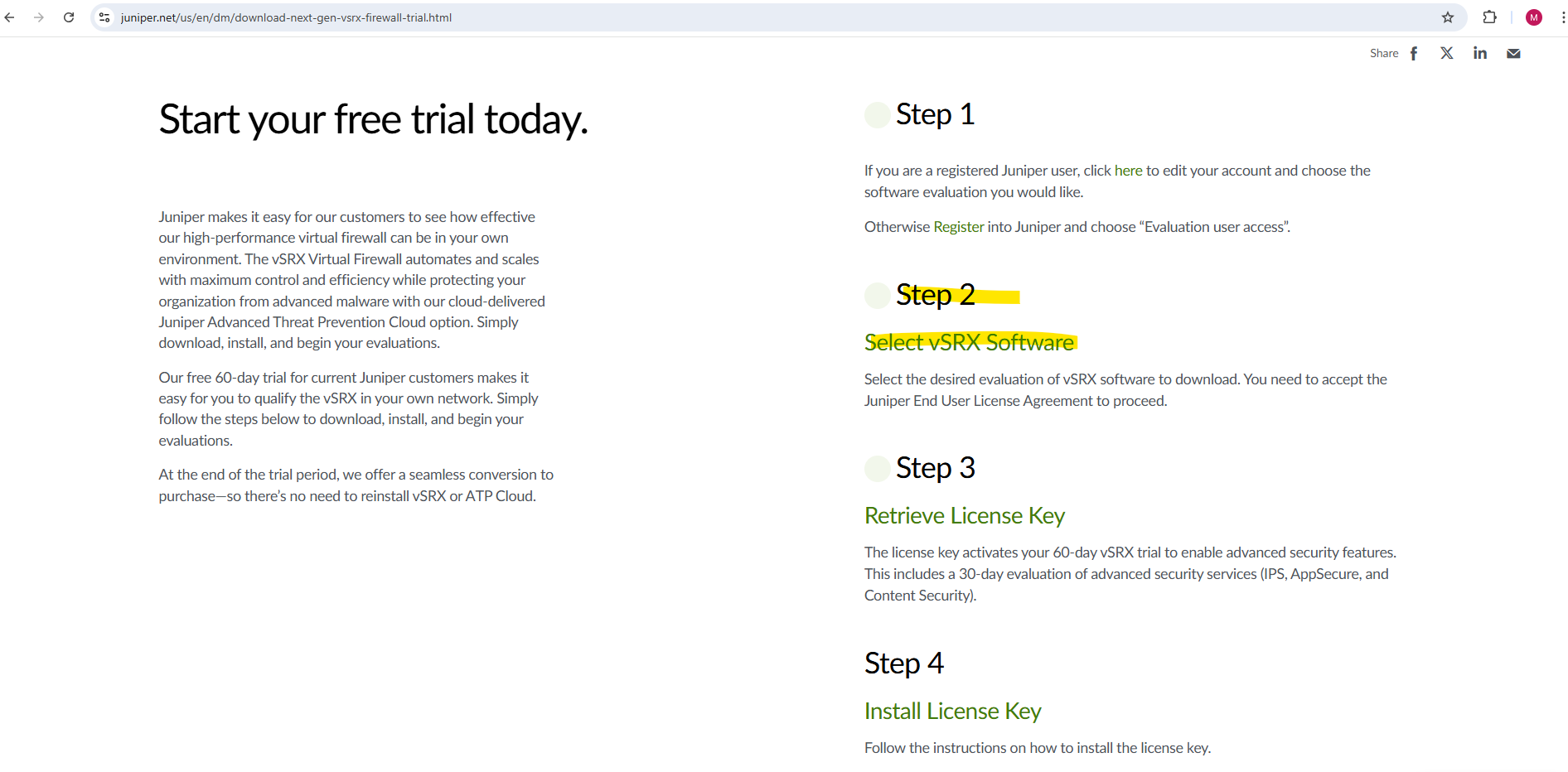
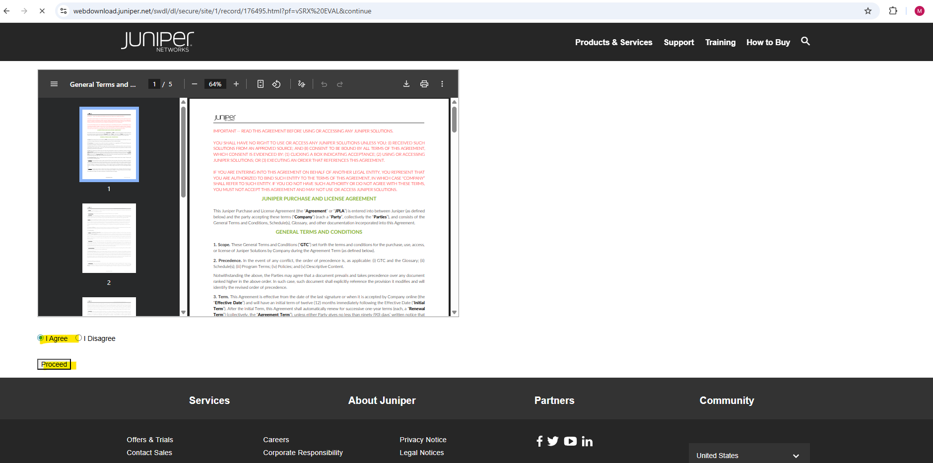
Accept the terms and click on proceed.
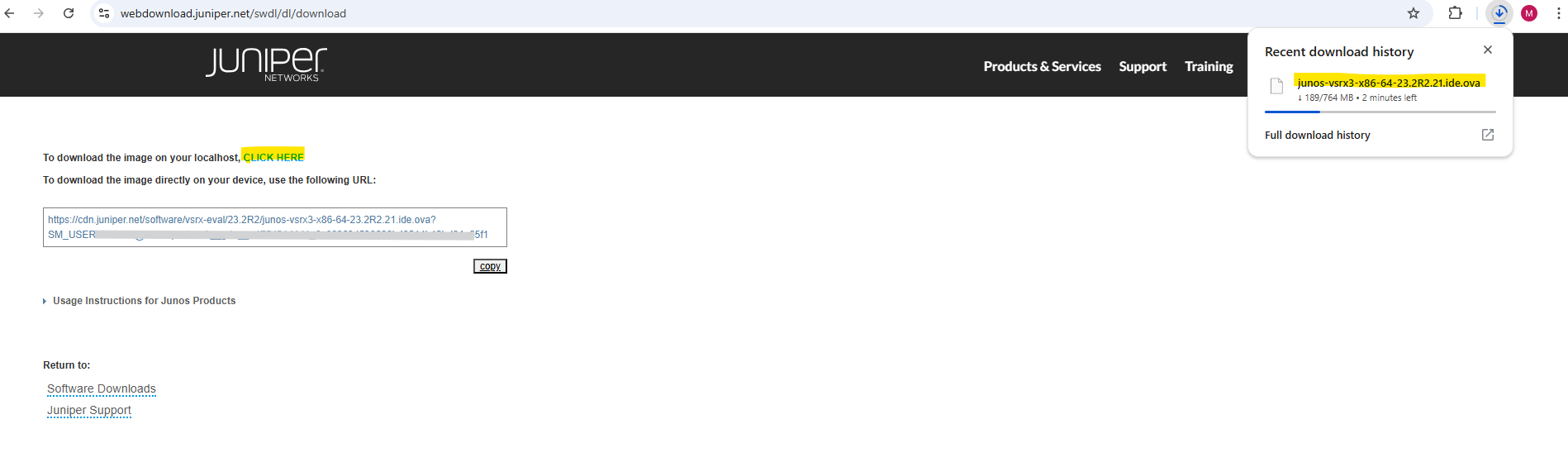
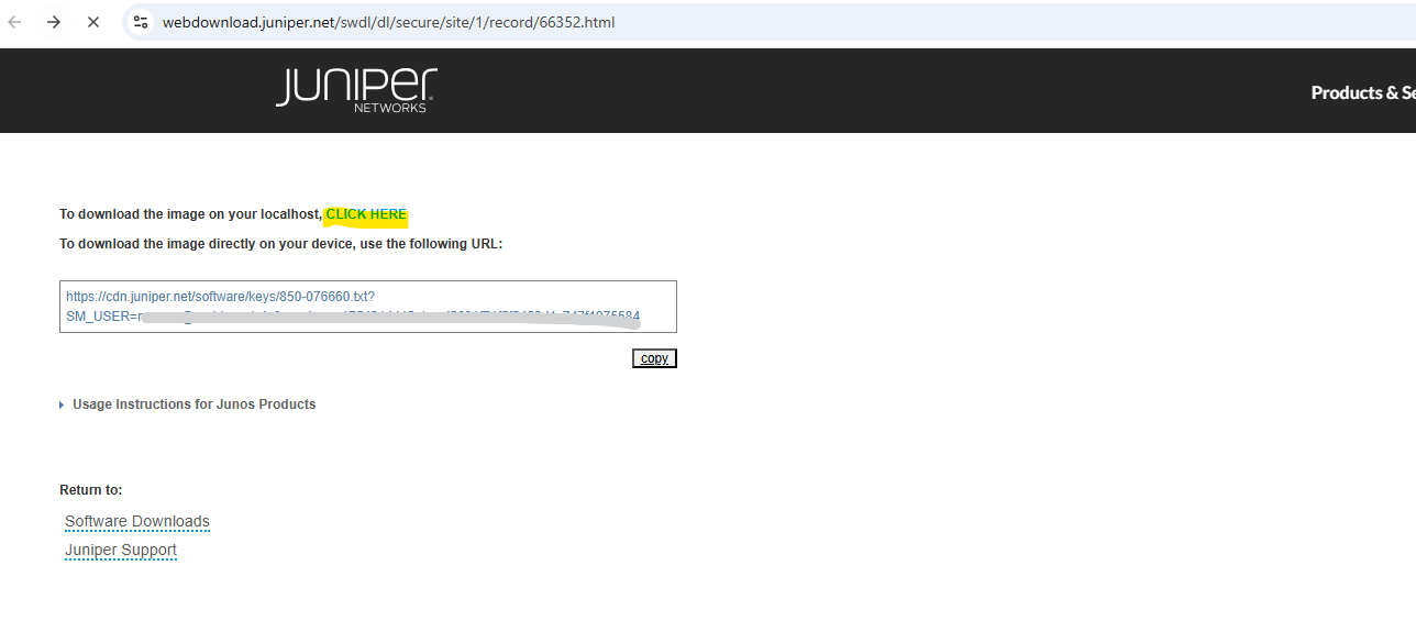
Click on the link below to download the appliance to your computer.
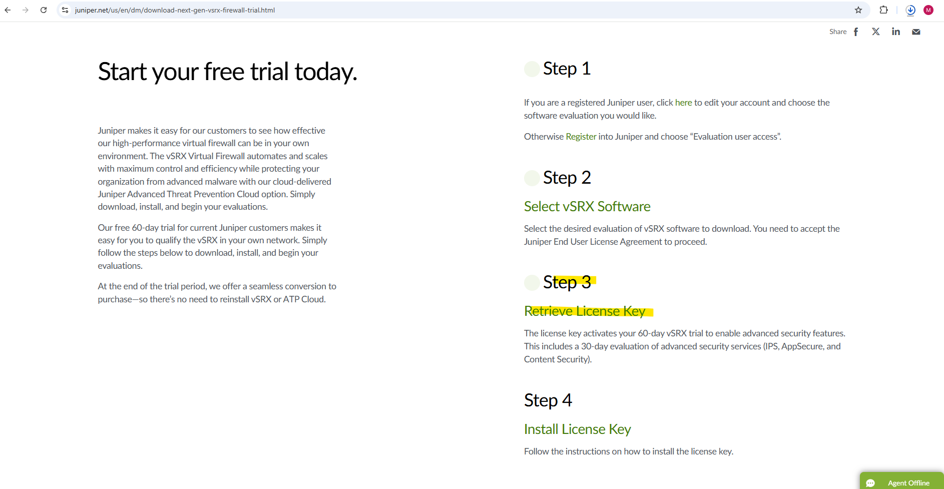
We also need to retrieve the trial license and install it later on the appliance. Therefore click on Retrieve License Key.
The license key activates your 60-day vSRX trial to enable advanced security features. This includes a 30-day evaluation of advanced security services (IPS, AppSecure, and Content Security).
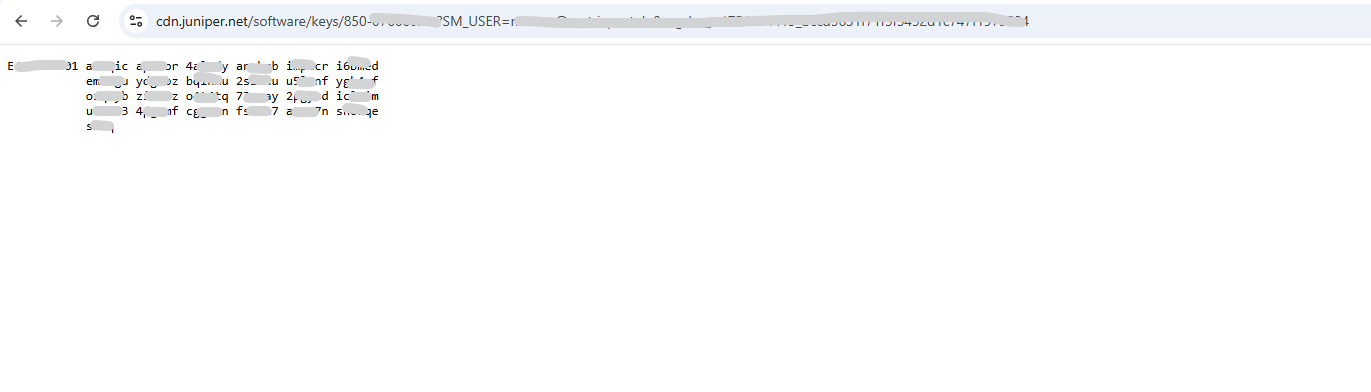
Looks like before when downloading the appliance also the description is misleading with to download the image …, finally you will get forwarded to a page including the license key when clicking the link below.
Copy the complete license key for later installation.
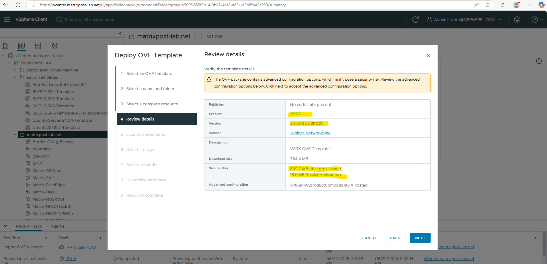
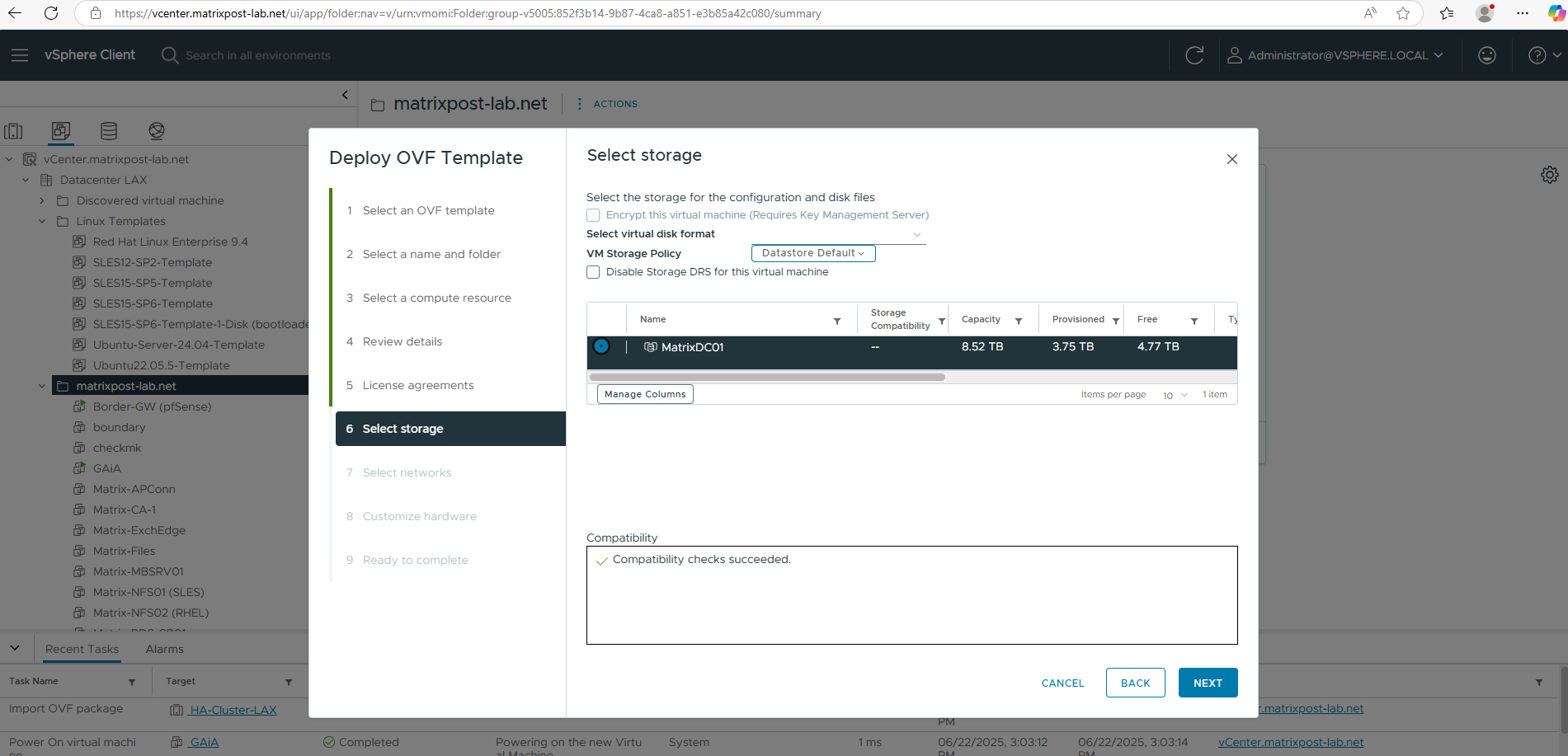
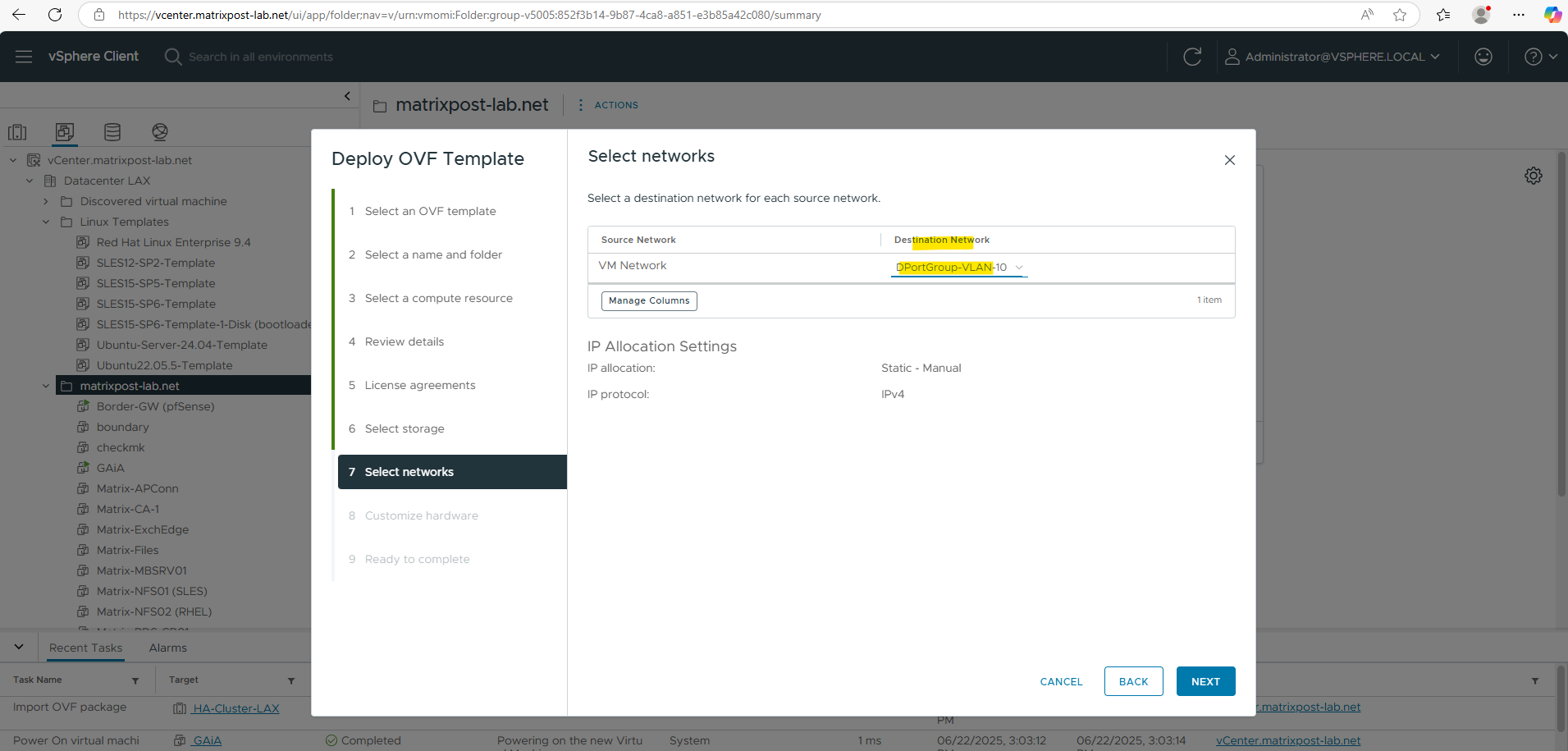
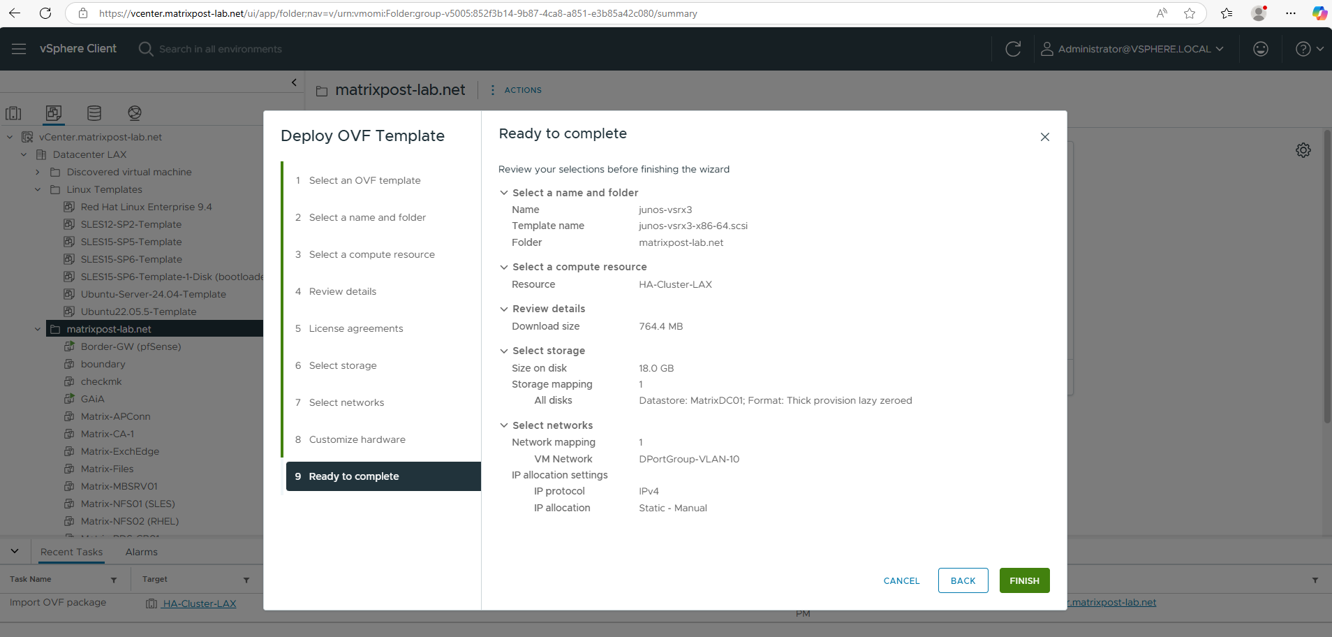
Deploy the Appliance (.ova File) in vSphere
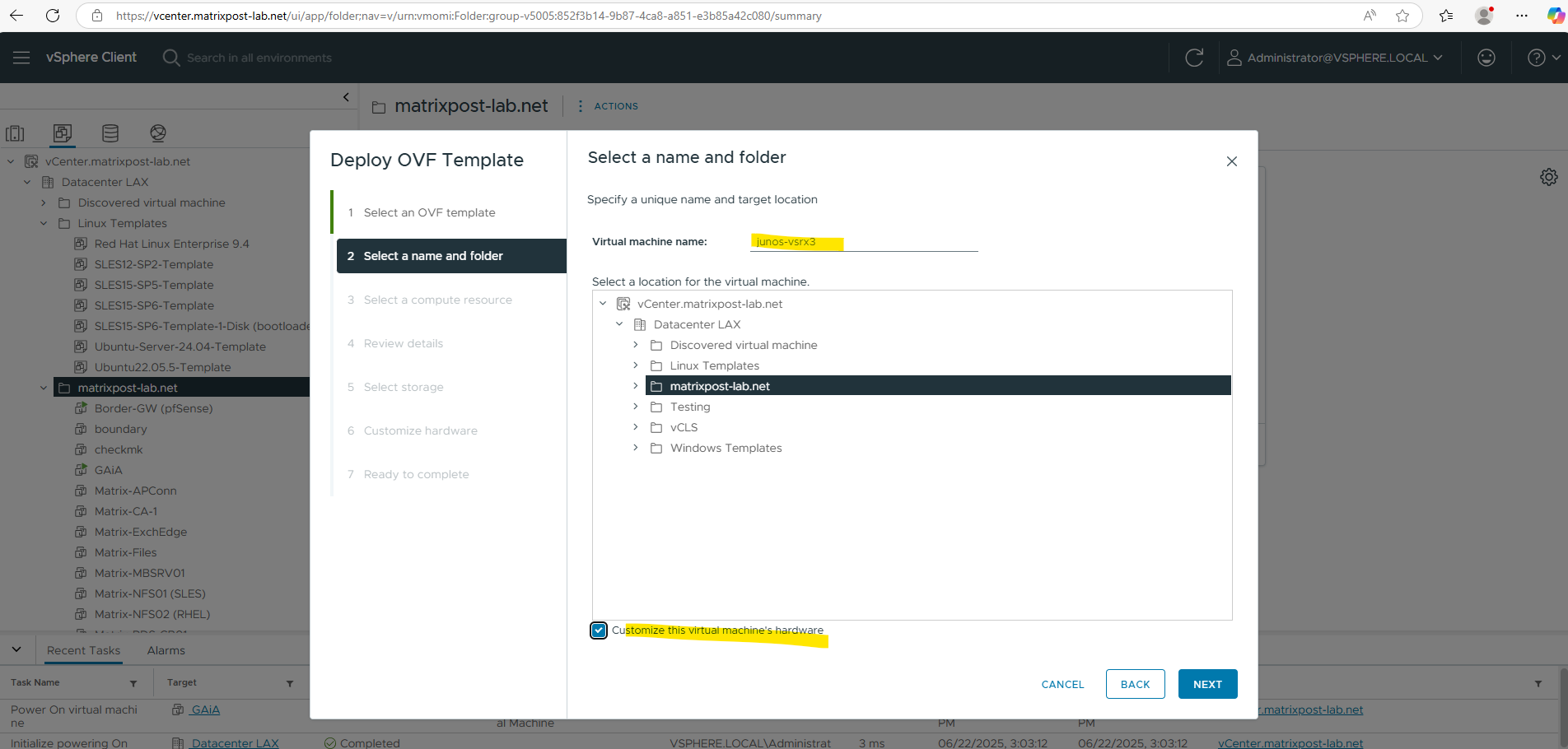
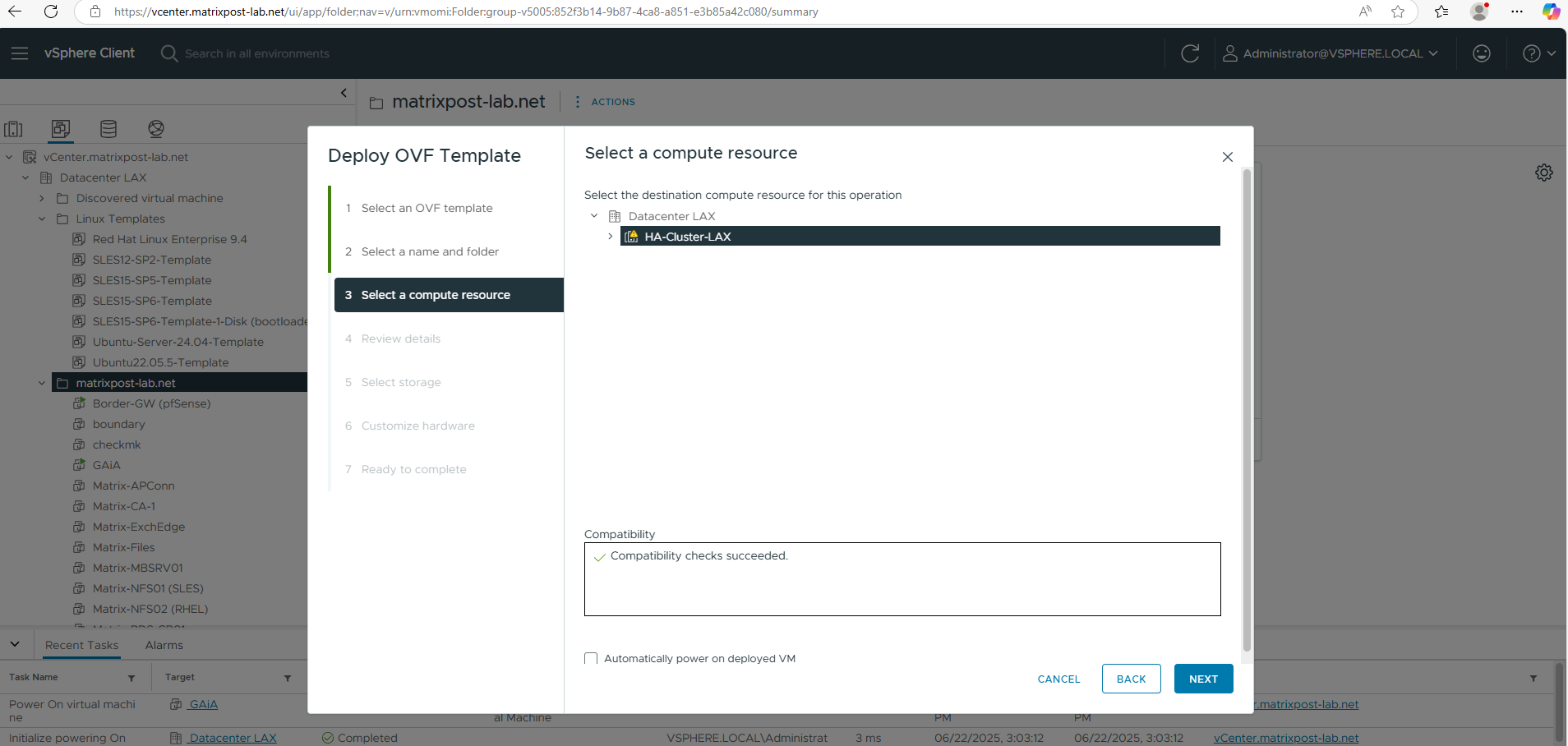
For the destination network I will select my internal LAN.
Finally this OVF template has three network adapters configured, we can adjust each of them to our needs after the deployment.
Finally click on FINISH to import and deploy the OVF package and template.
Configure Appliance
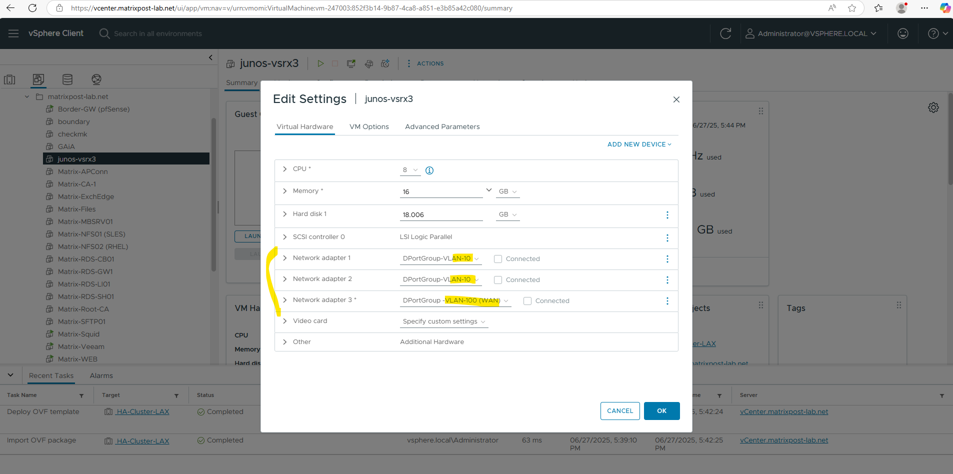
As mentioned the OVF template has three network adapters configured, we can now adjust them first before we power on the virtual machine.
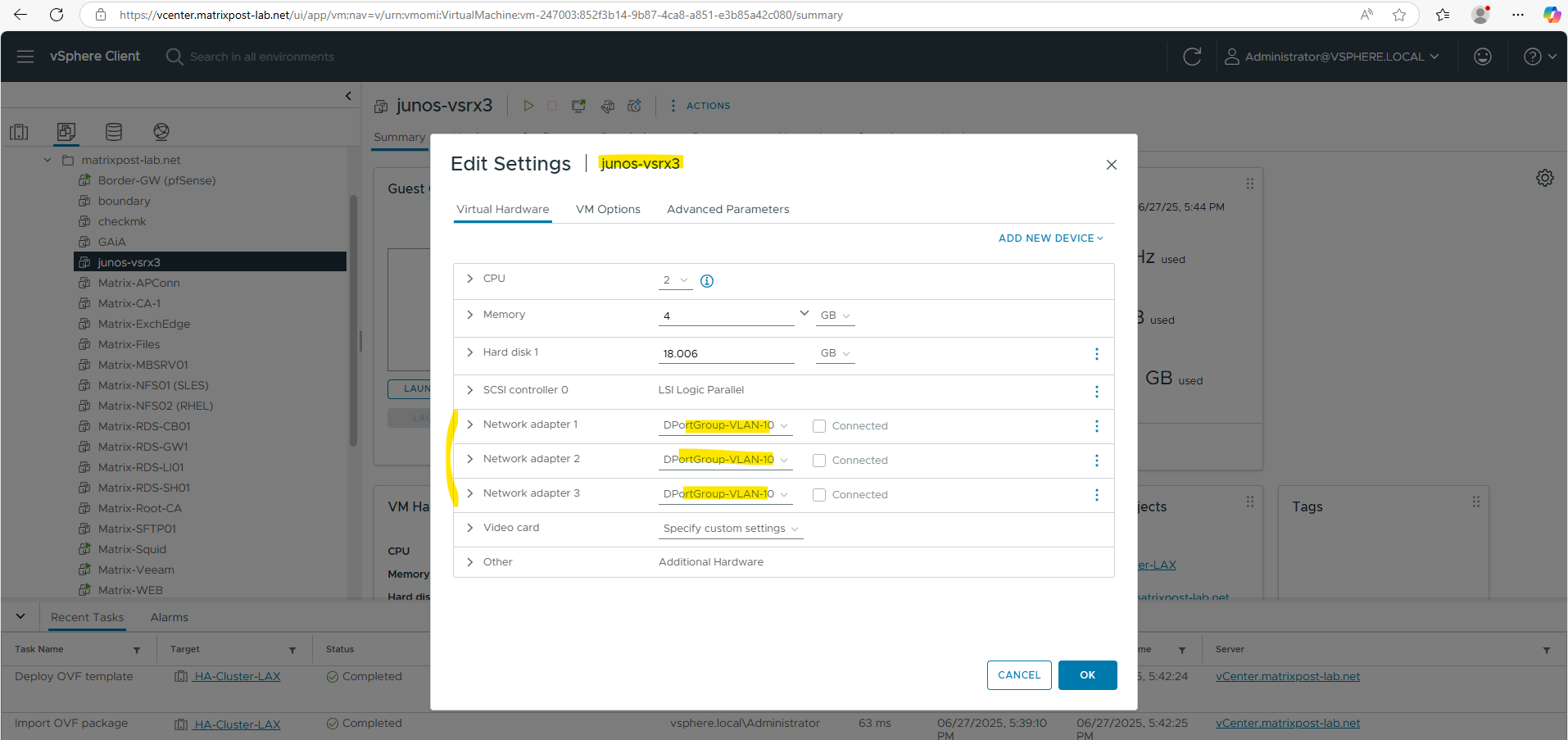
I will also increase the CPUs and RAM below. For the first two network adapters I will configure my internal LAN (VLAN-10), where the first will be the Out-of-Band Management Interface (aka fxp0) used only for device management, the second will be a data interface (aka ge-0/0/0 Gigabit Ethernet) connected to my internal LAN and used for regular routed traffic from the internal LAN, the last is also a data interface (aka ge-0/0/1) and used for regular routed traffic outbound/inbound to/from the WAN (Internet).
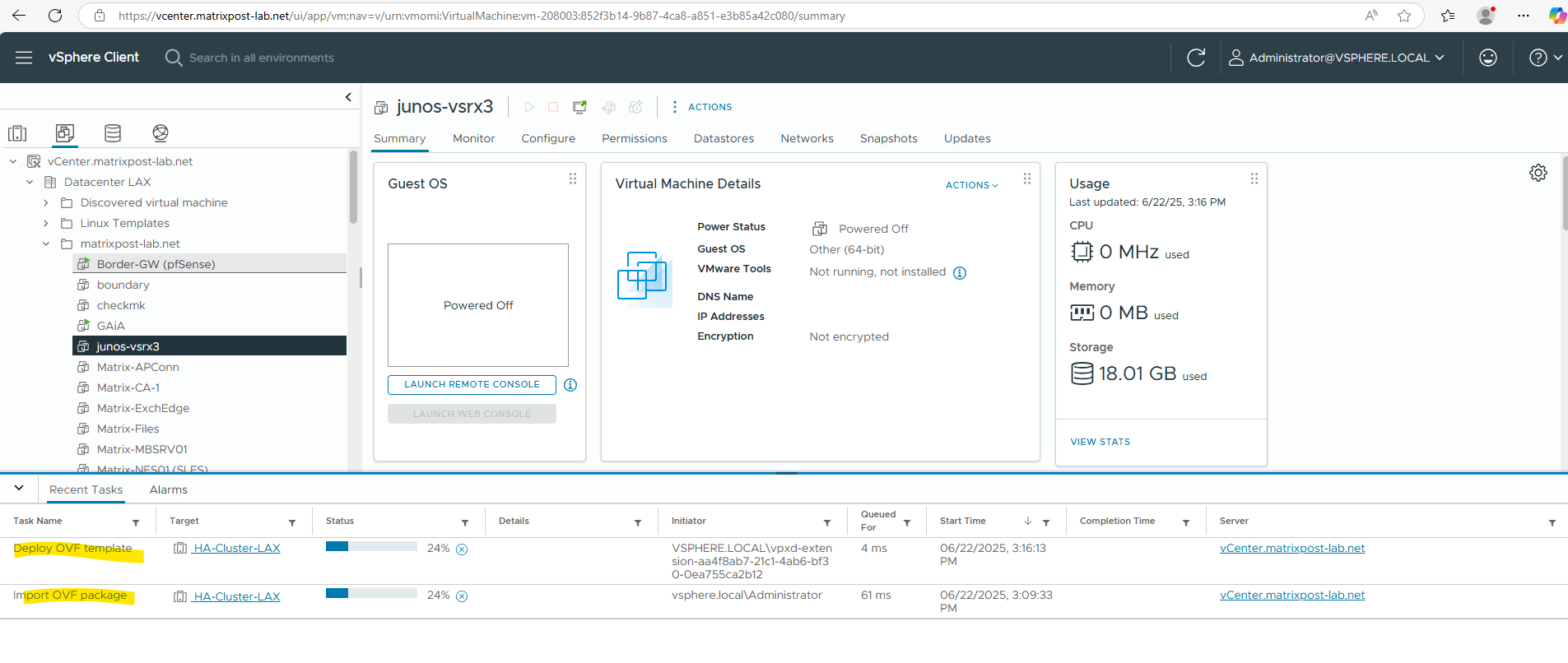
We can now power on the deployed virtual machine in vSphere.
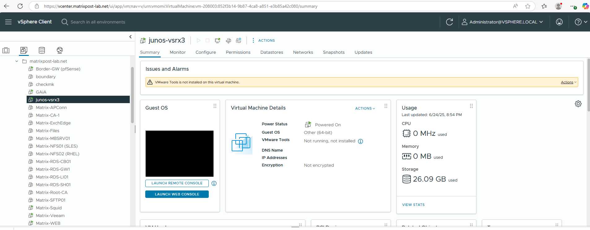
Below we can see already that the Juniper appliance is build on top of the FreeBSD OS as mentioned in the introduction section.
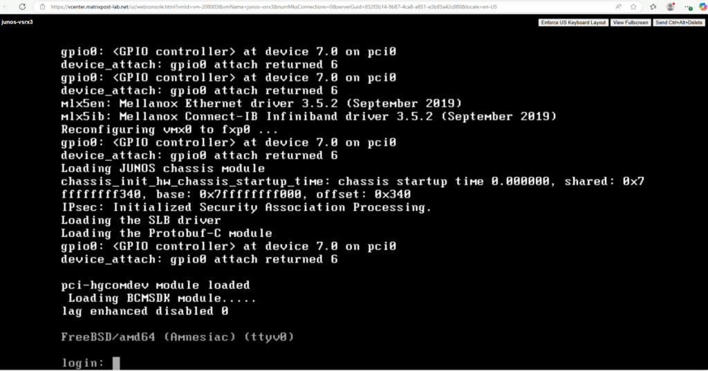
To login the first time just enter root for the login and press enter, so far no password is set for the root account.
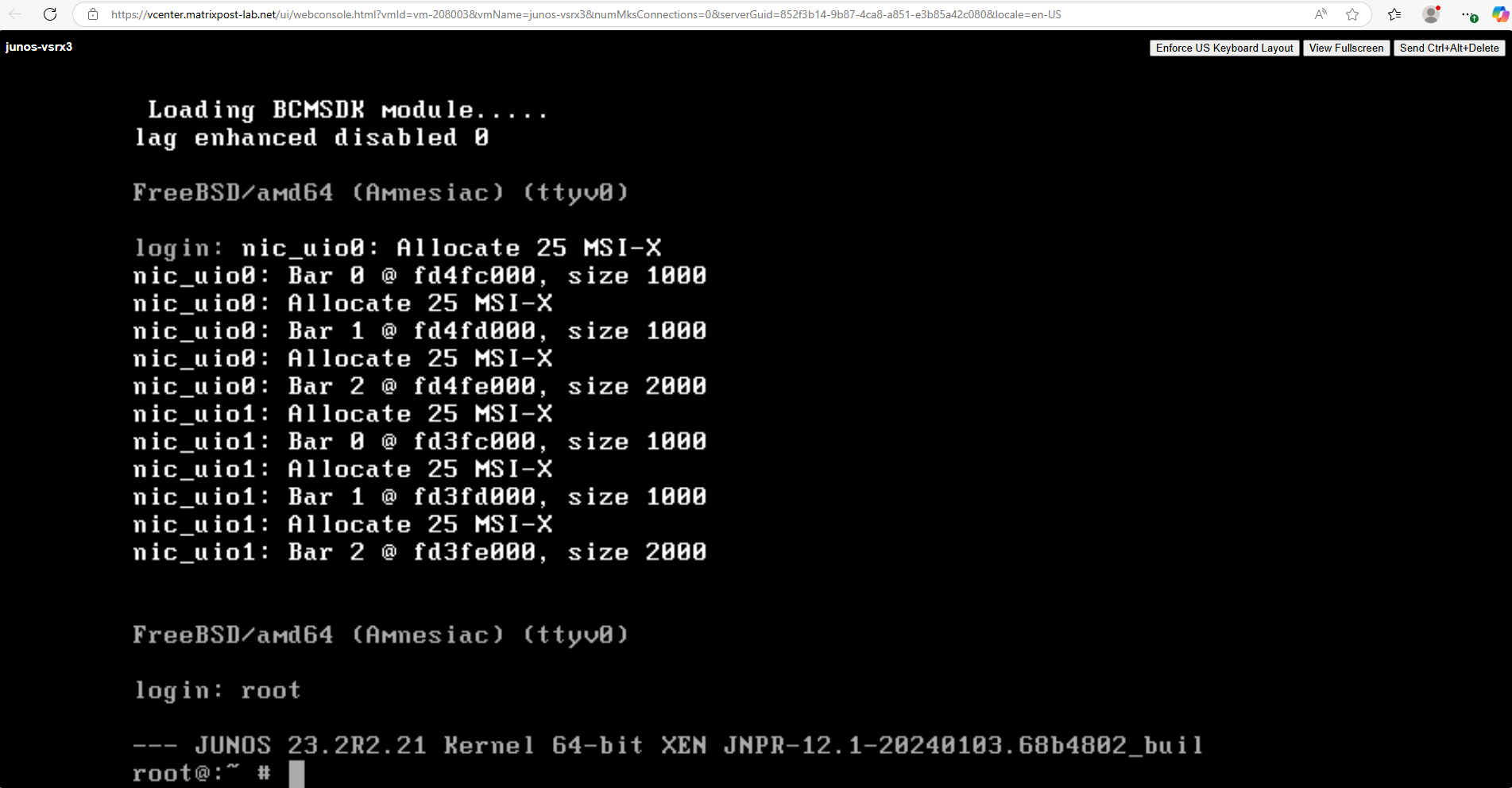
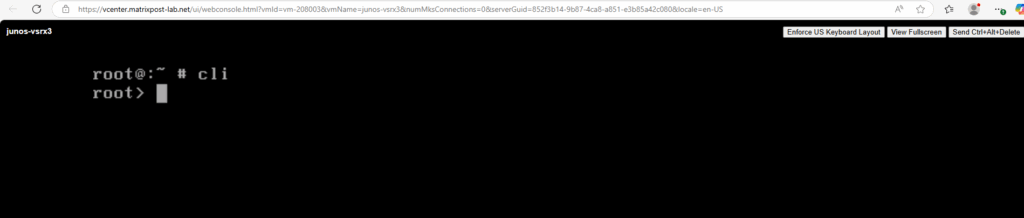
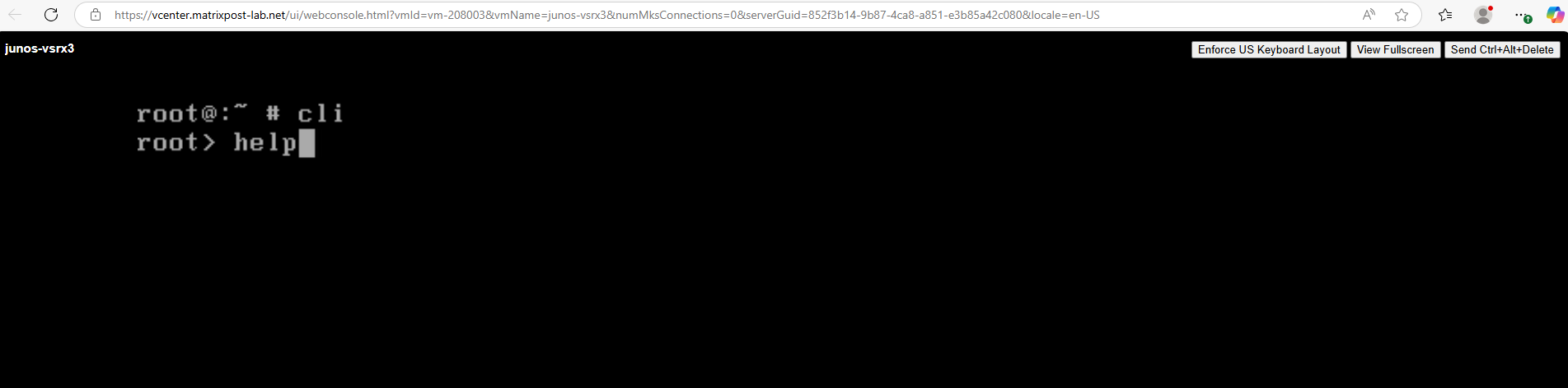
Enter the CLI (operational mode) on Juniper vsrx3.
root@:~ # cli
root>
Show the help.
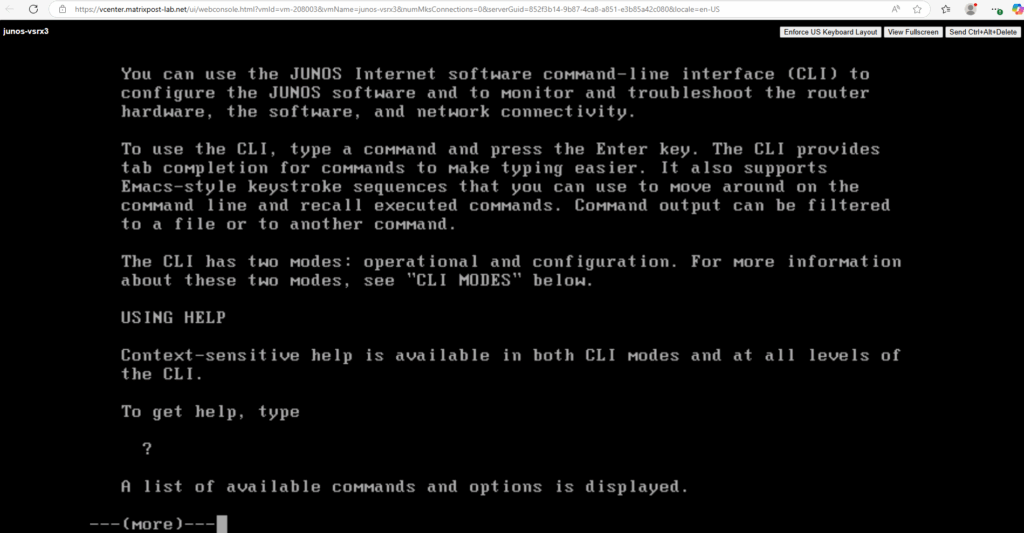
The CLI has two modes: operational and configuration. When you log on, you are in operational mode and the command-line prompt appears like this:
user@host>
You use operational mode commands to monitor and troubleshoot the software, hardware, and network connectivity.
You use configuration mode to configure the router or to modify an existing router configuration.
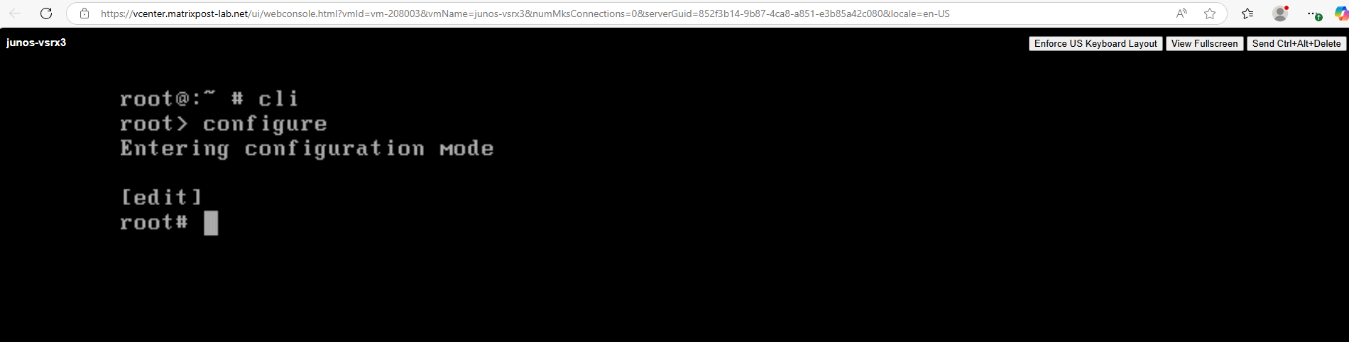
To enter configuration mode, type the configure command at the operational mode prompt:
user@host> configure
A banner that shows your location in the JUNOS edit configuration hierarchy is displayed in square brackets above the command-line prompt.
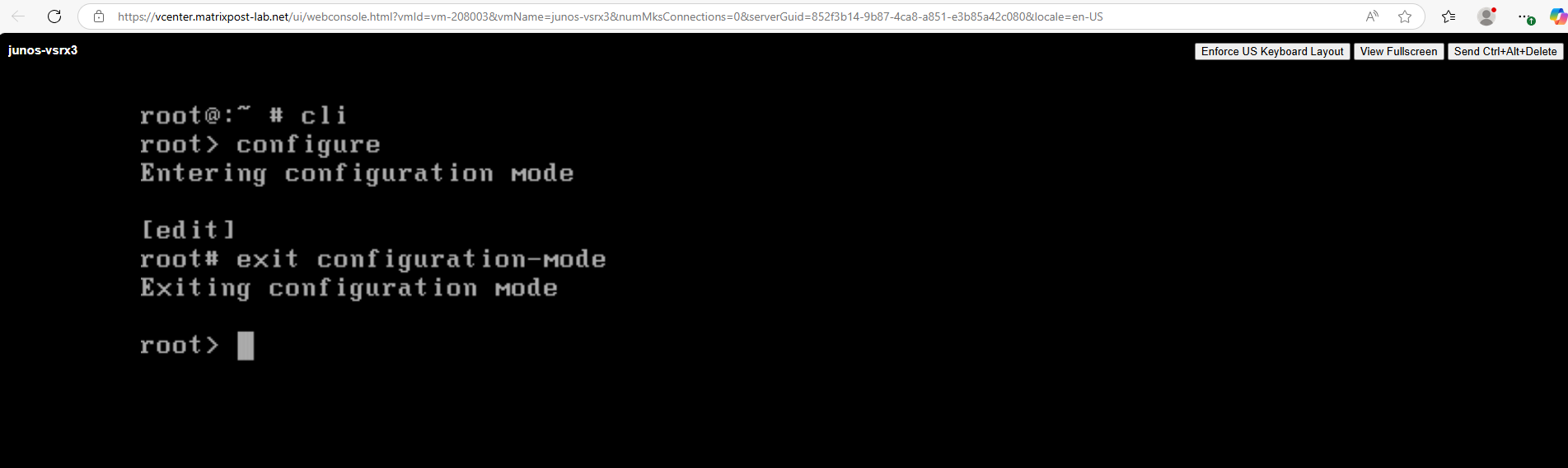
To exit configuration mode, type the exit:
user@host# exit configuration-mode
In order to enable SSH access we first need to set a password for the root user.
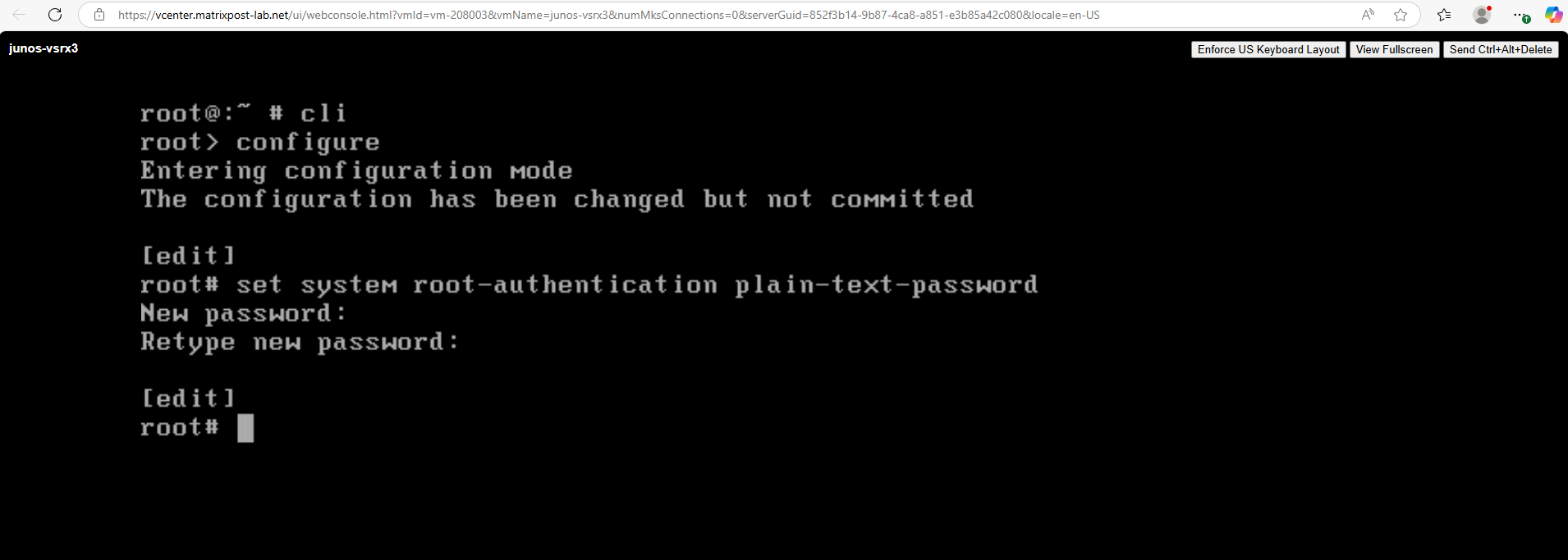
Configure a Plain-Text Password for Root Logins
root@:~ # cli
root> configure
root# set system root-authentication plain-text-password
root# commit
Next in order to connect from remote by using SSH or the Web UI, we first need to configure the Out-of-Band Management Interface (fxp0).
Configure Management Interface (fxp0)
The network adapter for each interface uses SR-IOV or VMXNET 3 as the adapter type. The first network adapter is for the management interface (fxp0) and must use VMXNET 3.
All additional network adapters should have the same adapter type. The three network adapters created by default use VMXNET 3.
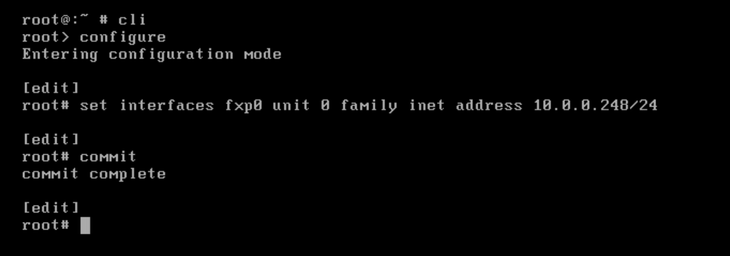
Configure the management interface (fxp0) .
root@:~ # cli
root> configure
root# set interfaces fxp0 unit 0 family inet address 10.0.0.248/24
root# commit
To delete an IP address on a interface we can use the delete interfaces command shown below.
root# delete interfaces fxp0 unit 0 family inet address 10.0.0.248/24
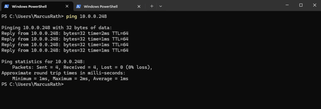
We can now already ping the management interface (fxp0).
So next we can enable SSH on the appliance.
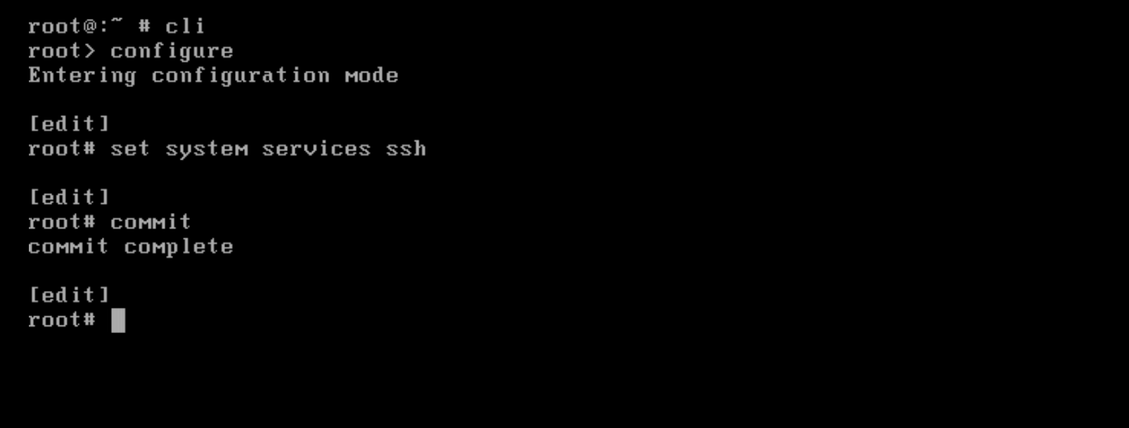
Enable SSH
This enables SSH on all interfaces by default, including fxp0.
root@:~ # cli
root> configure
root# set system services ssh
root# commit
So far I cannot login by SSH and using the root user account.
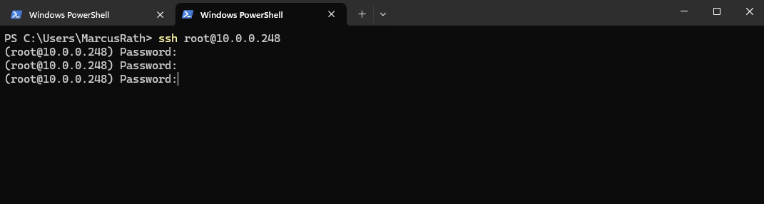
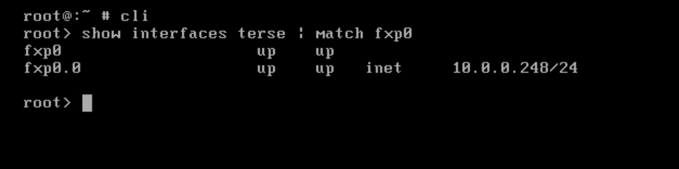
I will first check if the management interface (fxp0) is up and the IP address is assigned correct. Looks good.
root@:~ # cli
root> show interfaces terse | match fxp0
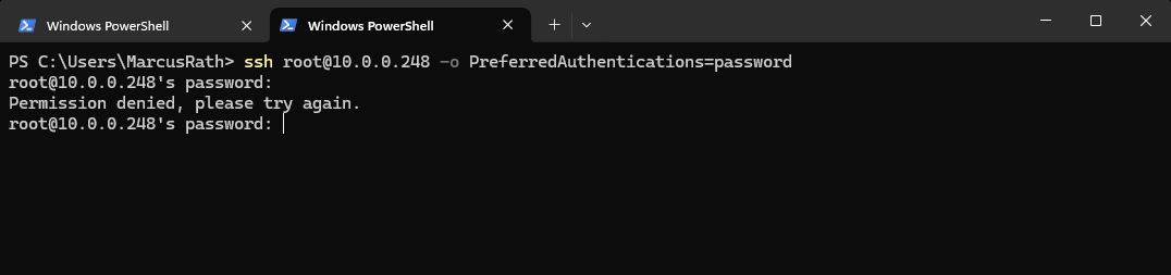
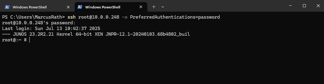
Force SSH to use password authentication. Now I get an permission denied error.
This forces password authentication (not publickey or interactive), which sometimes helps isolate the issue.
Since I am getting Permission denied even when forcing password authentication, it strongly suggests the Juniper vSRX3 is intentionally blocking SSH logins for the root user, even though it prompts for the password.
This is expected behavior by default on many Junos-based systems for security reasons.
> ssh root@<fxp0 IP> -o PreferredAuthentications=password
We need to explicitly allow root login via SSH in the configuration.
root@:~ # cli
root> configure
root# set system services ssh root-login allow
root# commit

to be more restrictive (allow only if a password is set):
root# set system services ssh root-login allow-password
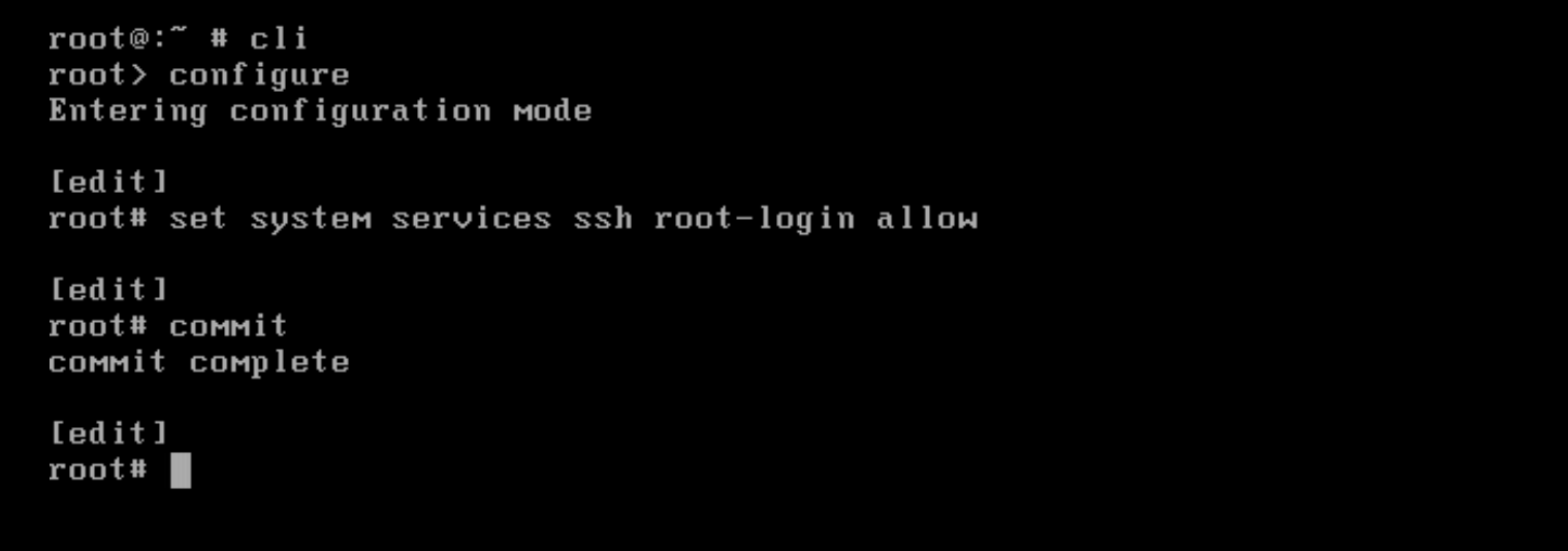
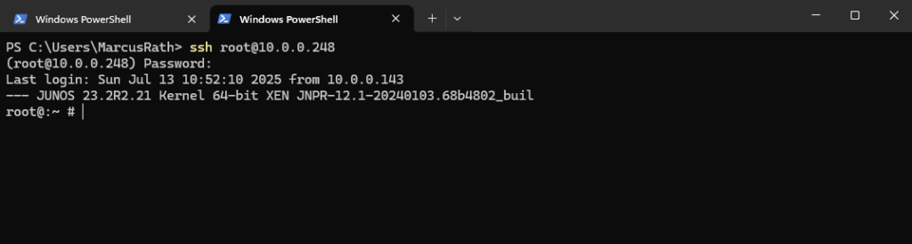
Now it works.
> ssh root@10.0.0.248 -o PreferredAuthentications=password
Also without the above flag for the preferred authentication method.
> ssh root@10.0.0.248
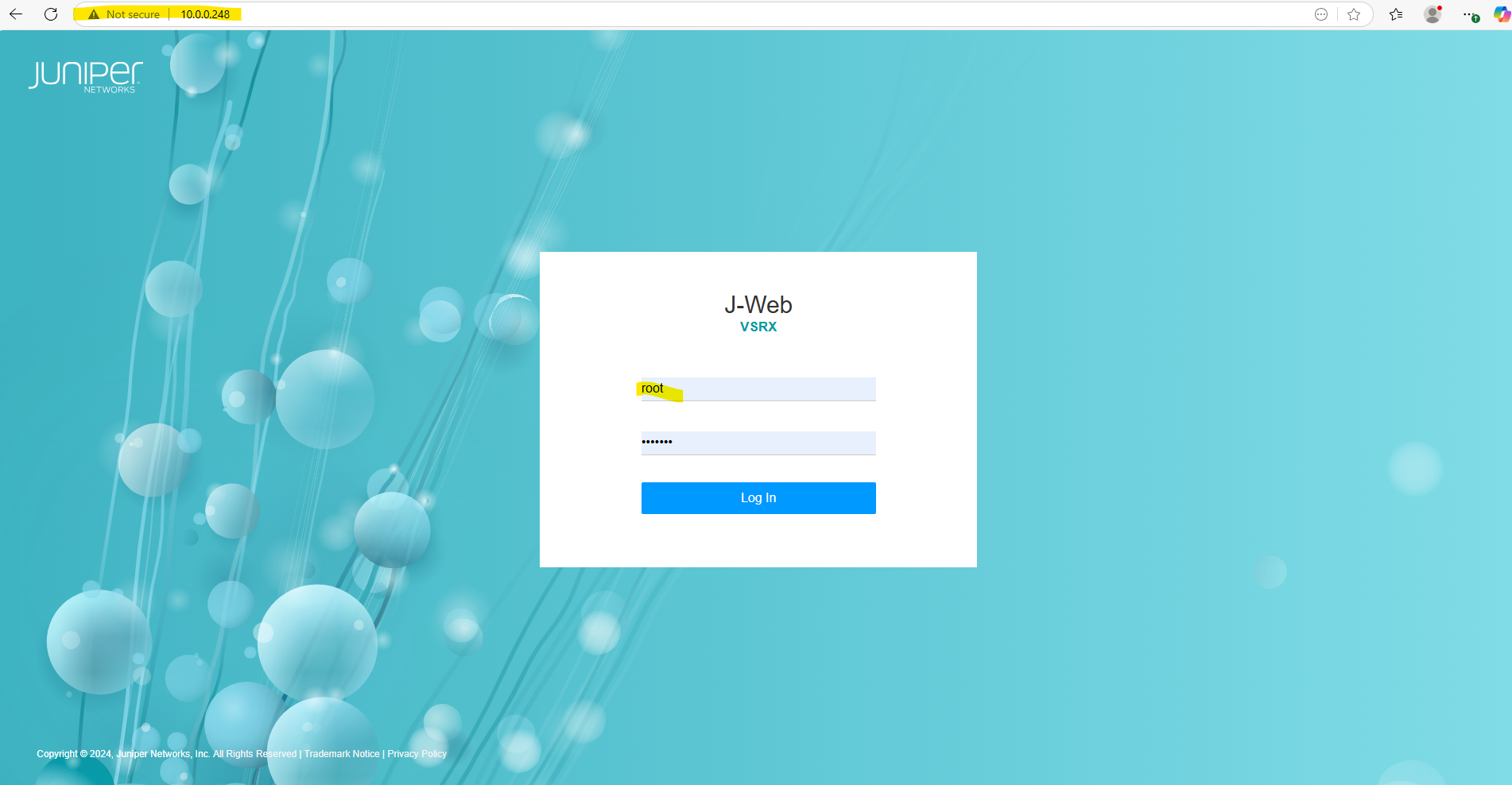
After configuring the Management Interface (fxp0), we can also sign-in to the Web UI of the appliance by using the root user account and plain http.
http://<ip Management Interface (fxp0)>
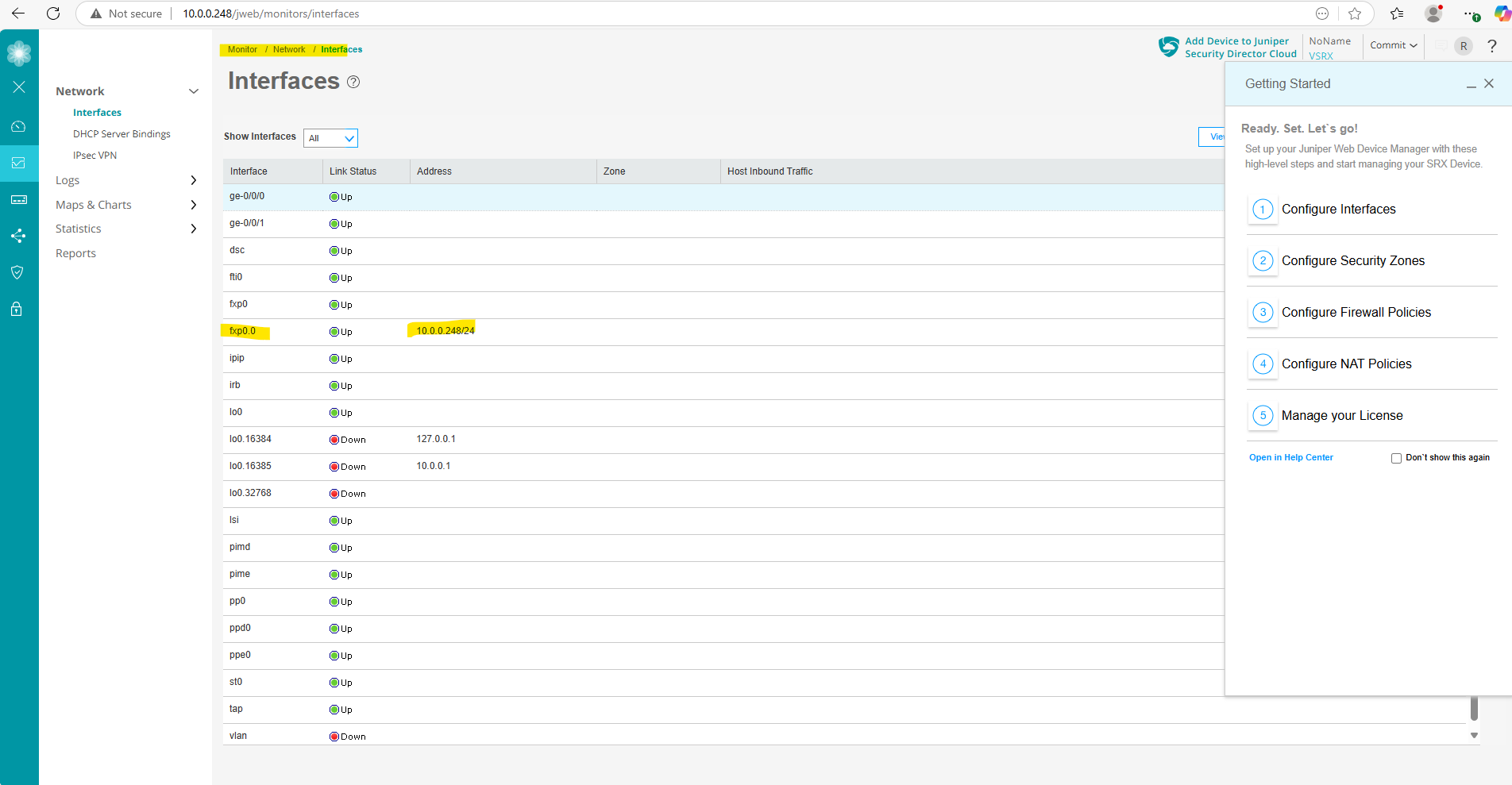
Here under Monitor -> Network -> Interfaces we could see our previous configured Management Interface (fxp0) and its IP address 10.0.0.248/24.
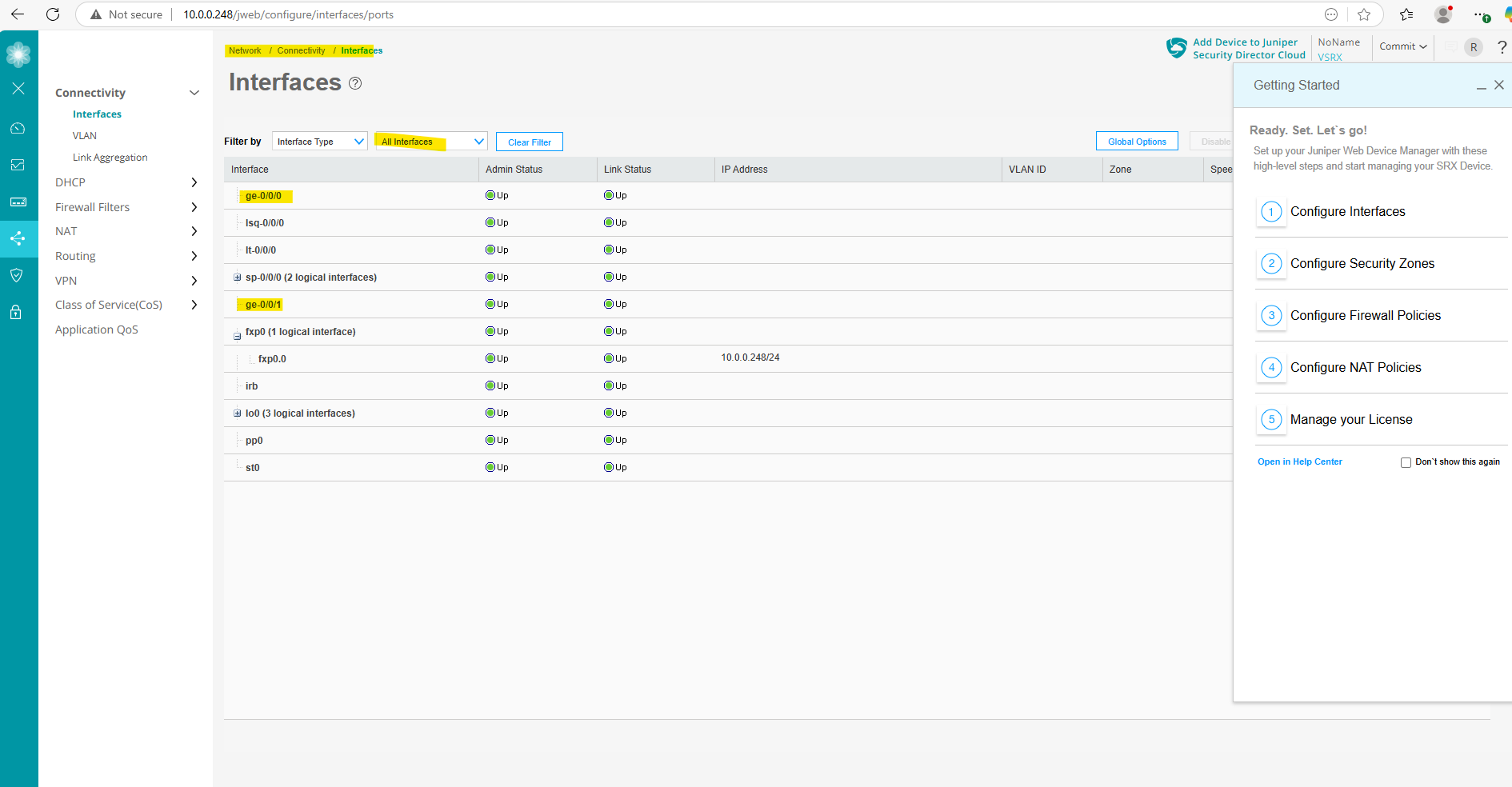
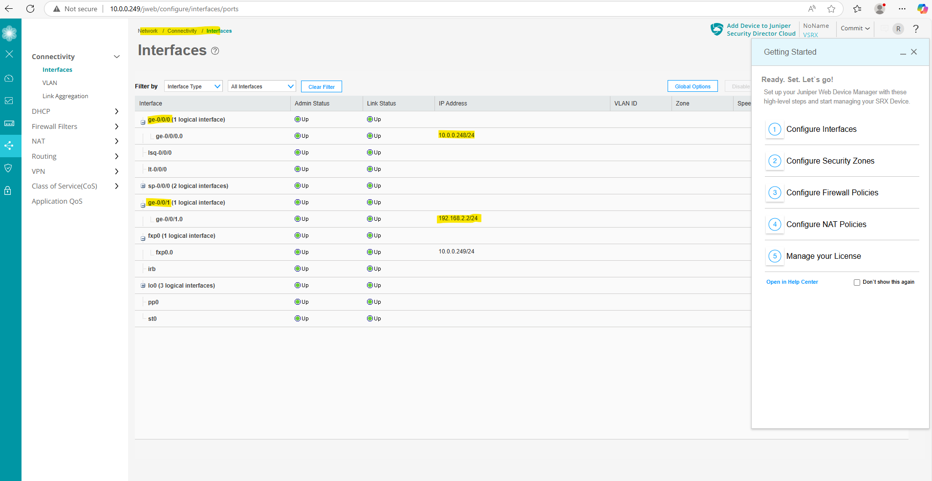
Or under Network -> Connectivity -> Interfaces.
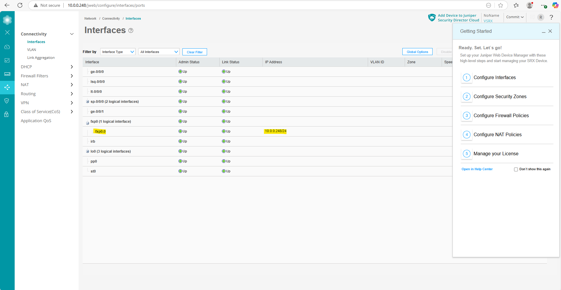
We can also see here the other two network interfaces (ge-0/0/0 and ge-0/0/1) the VMware template was including.
ge-0/0/0 and ge-0/0/1 are the data interfaces which will be used for regular routed traffic as mentioned further above. In my case ge-0/0/0 is connected to the internal LAN and ge-0/0/1 for outbound/inbound access from/to the WAN (actually the DMZ, my Juniper appliance sits behind a NAT router (FRITZ!Box in my case). More about this scenario you will find here https://blog.matrixpost.net/azure-ipsec-vpn-tunnel-onpremise/.
So next we need to configure these both network interfaces (ge-0/0/0 and ge-0/0/1), but first we will install the trial license key.
Install the Trial License
To install an individual license key we can use the Junos OS CLI as shown below.
The first part with E4…… is the name parameter which includes the license ID and the license key, in my case here a trial license.
root@junos-vsrx3> set system license keys key "E4XXXXXX01 xxxxxx xxxxxx xxxxxx xxxxxx xxxxxx xxxxxx xxxxxx xxxxxx xxxxxx xxxxxx xxxxxx xxxxxx xxxxxx"
We can view the license by running.
root@junos-vsrx3> show system license
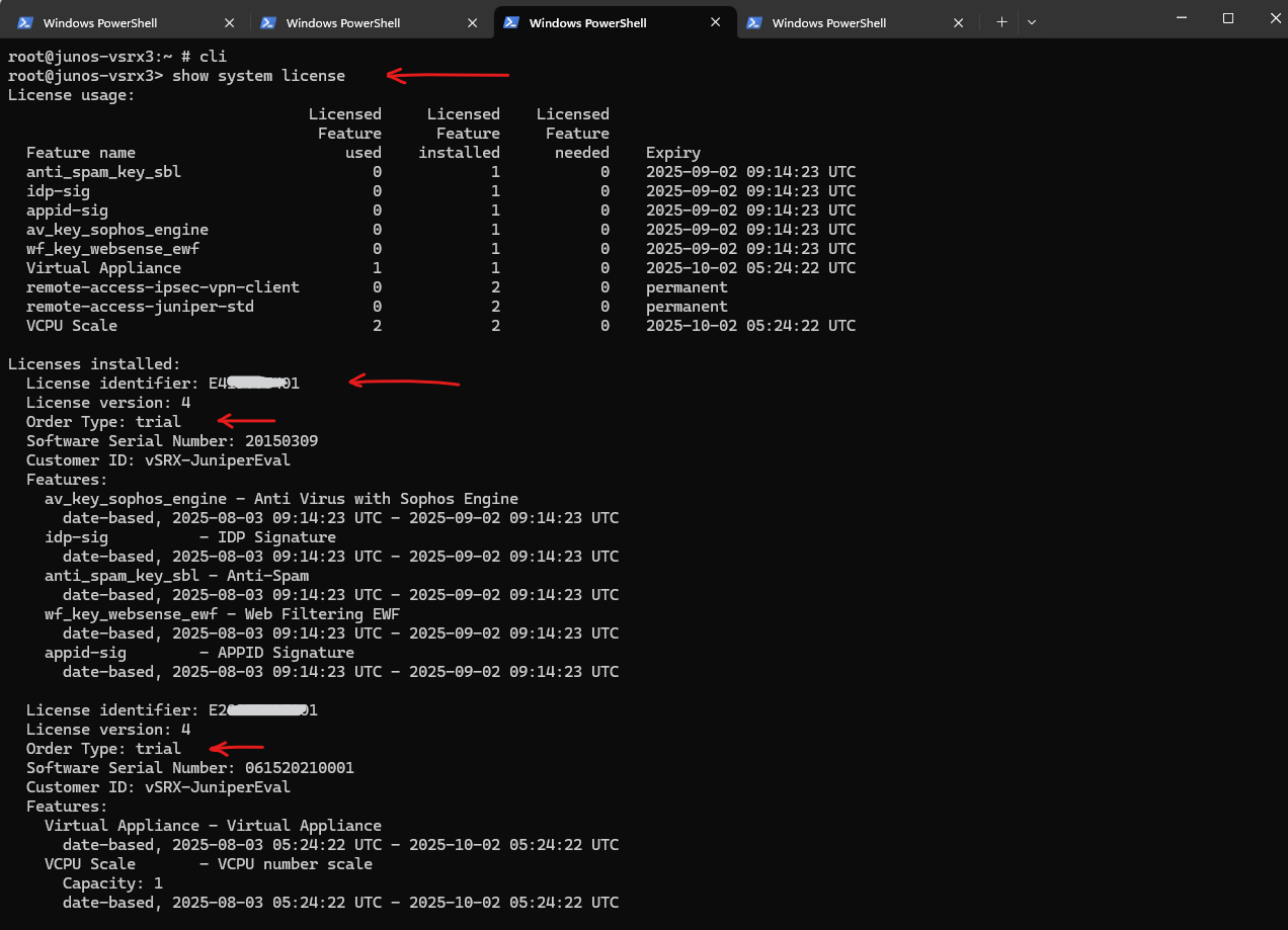
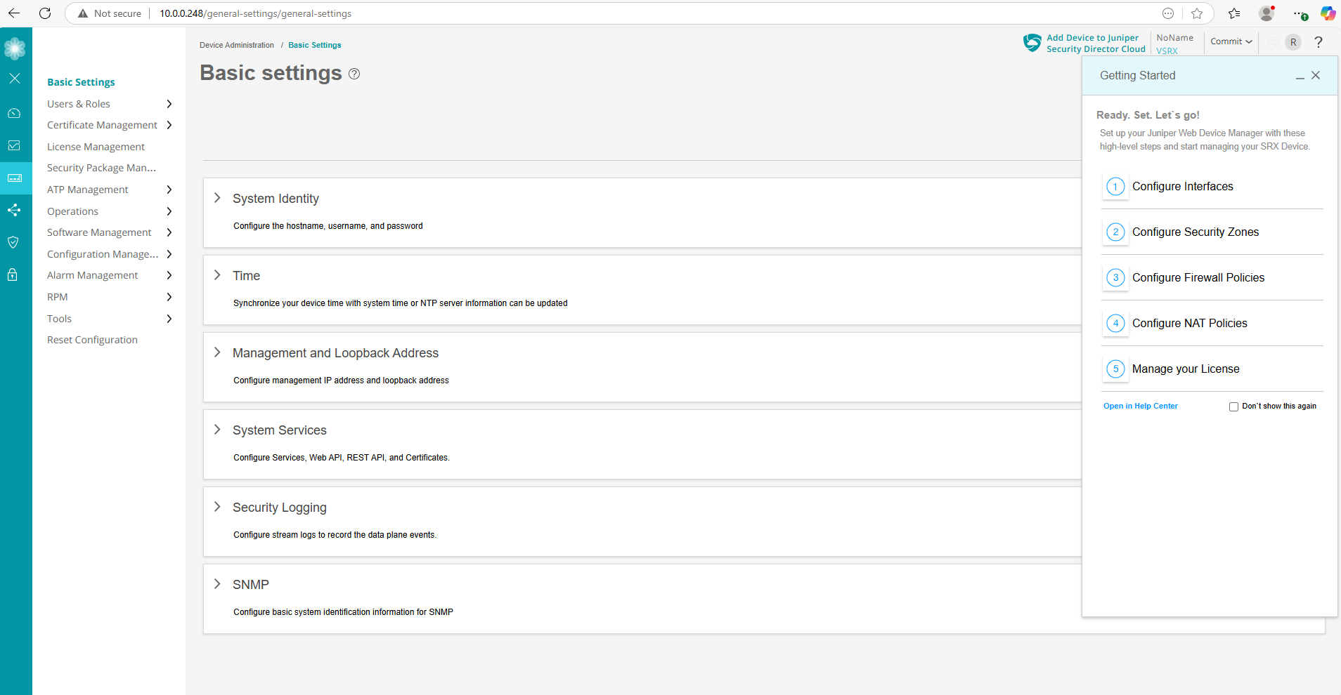
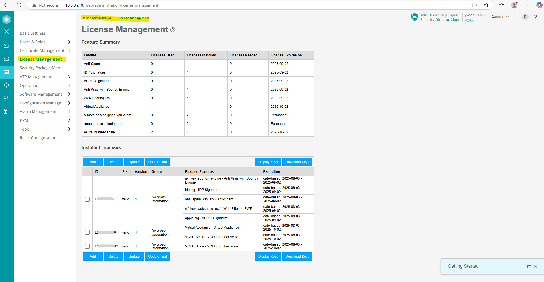
Or by using the Web UI under Device Administration -> License Management.
Configure the Data Interfaces (ge-0/0/0 and ge-0/0/1)
We can configure the data interfaces also like previously for the management interface (fxp0) by using the CLI or now also by using the Web UI.
First I want to check and be sure which virtual network adapter on VMware vSphere finally is really assigned as ge-0/0/0 and ge-0/0/1.
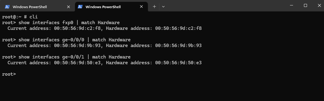
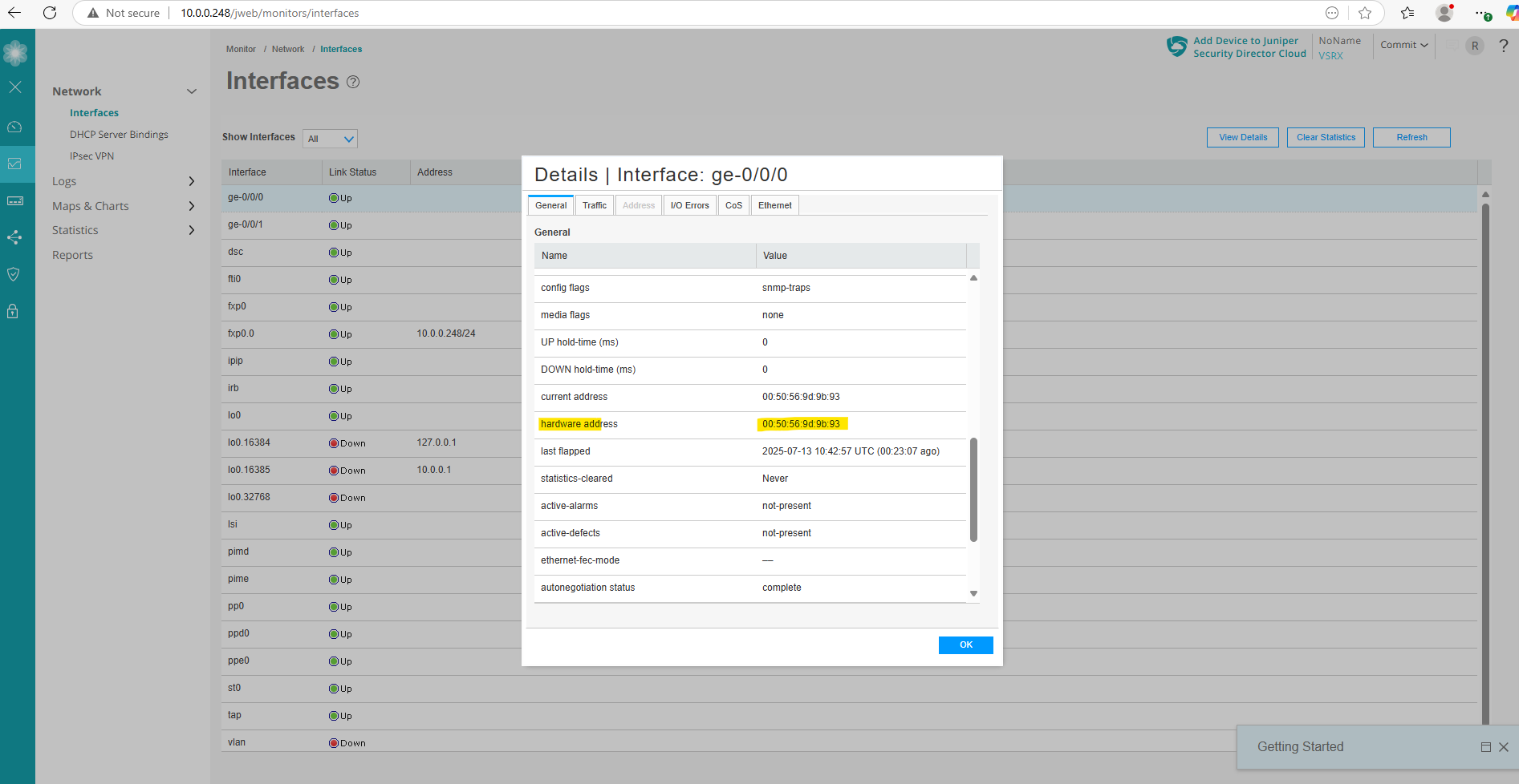
To check the MAC (hardware address) of the adapters on the Juniper appliance we can use the following CLI commands.
root@:~ # cli
root> show interfaces fxp0 | match Hardware
root> show interfaces ge-0/0/0 | match Hardware
root> show interfaces ge-0/0/1 | match Hardware
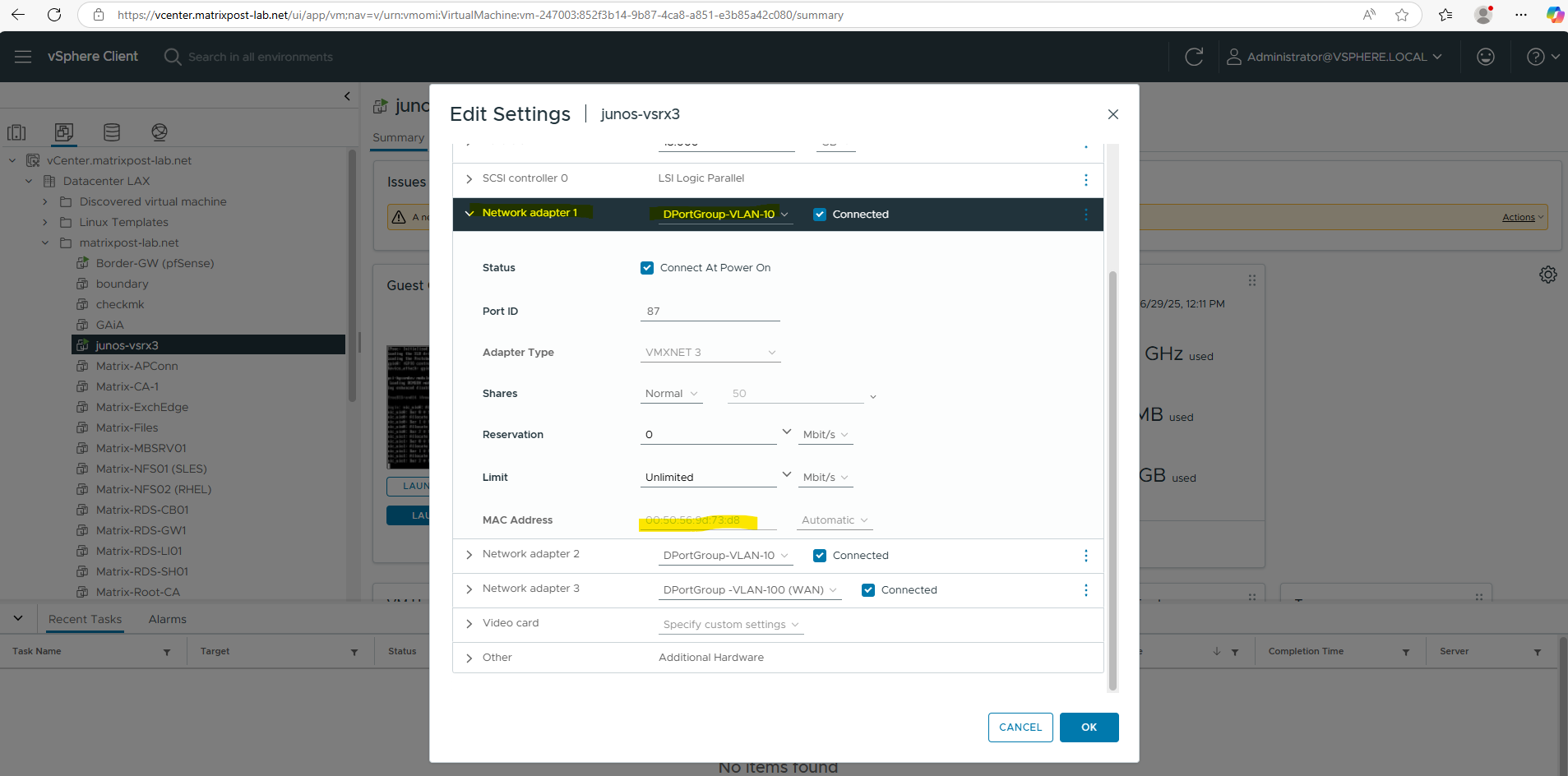
We can also check this on vSphere.
My first network adapter connected to the internal LAN (VLAN-10) is correctly assigned for the management interface (fxp0).
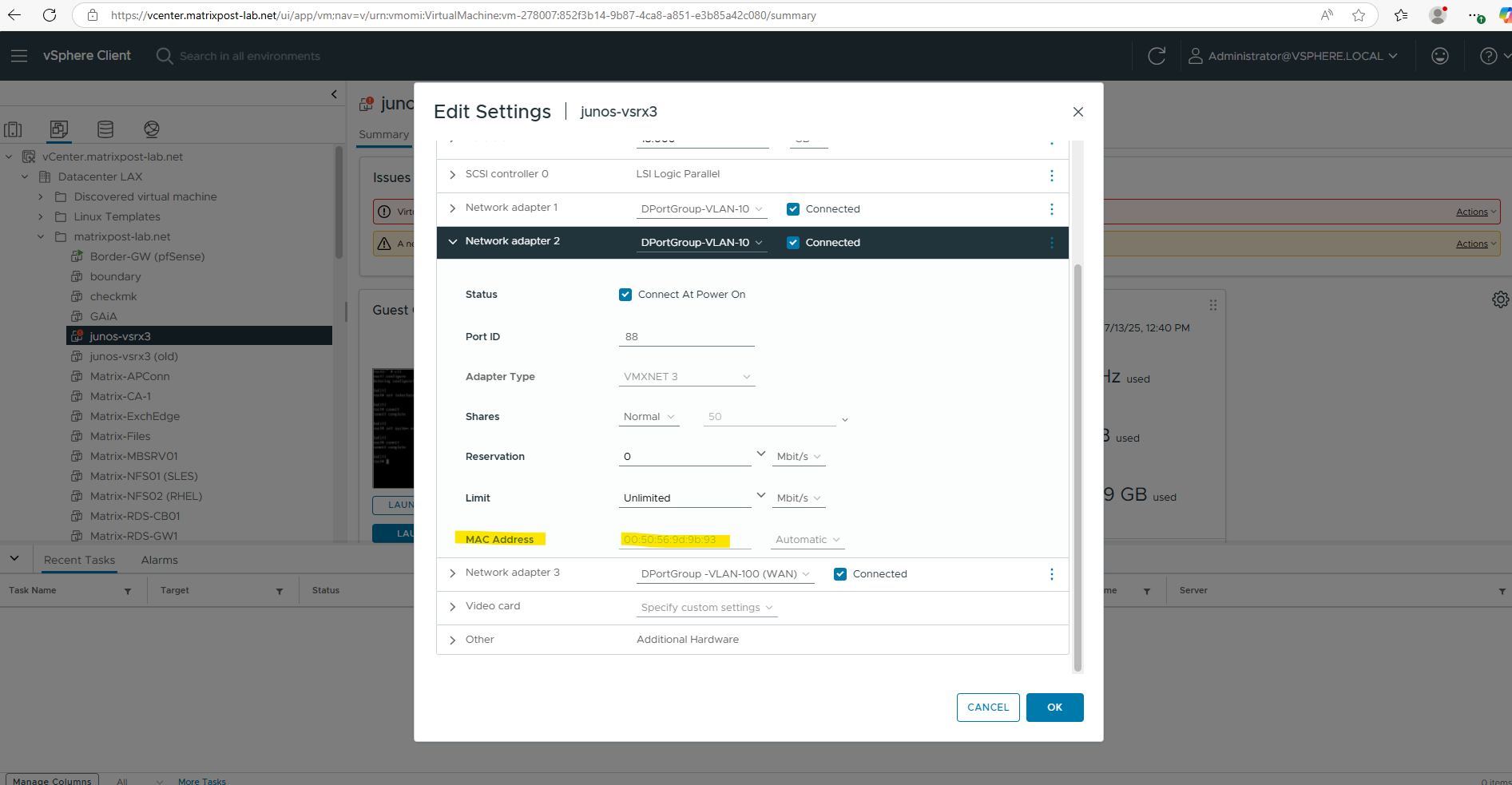
The second network adapter also connected to the internal LAN (VLAN-10) is correctly assigned for the internal data interface ge-0/0/0.
And finally the third network adapter connected to the WAN (VLAN-100) is also correctly assigned for the external data interface ge-0/0/1.
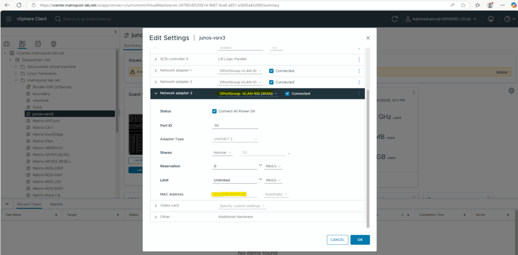
The MAC (hardware addresses) of the data interfaces ge-0/0/0 and ge-0/0/1 we can also check on the Web UI, the MAC address for the management interface (fxp0) will not shown here and we have to use the CLI instead.
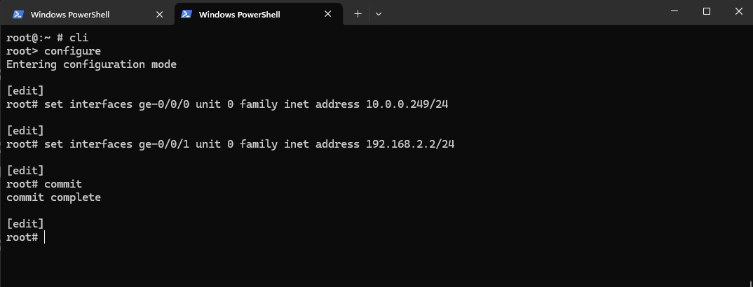
So now we can configure and assign the IP address for both data interfaces.
root@:~ # cli
root> configure
root# set interfaces ge-0/0/0 unit 0 family inet address 10.0.0.249/24
root# set interfaces ge-0/0/1 unit 0 family inet address 192.168.2.2/24
root# commit
By using the delete interface command below we can remove and delete the configuration.
root# delete interfaces ge-0/0/0 unit 0 family inet address 10.0.0.249/24
We can already see the new configuration on the Web UI under Monitor -> Network -> Interfaces.
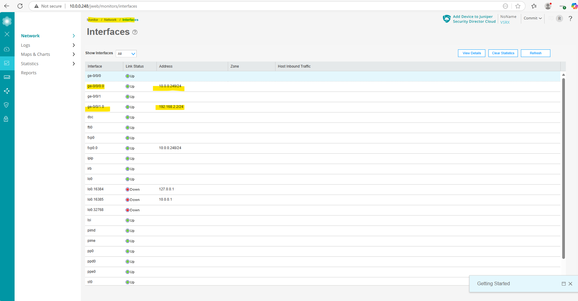
Also under Network -> Connectivity -> Interfaces
Next we will configure the name servers the appliance should use for name resolution.
Configure the Name Servers
Configure your Juniper Networks device to use one or more name servers. For redundancy, as a best practice, configure access to multiple name servers, up to a maximum of three servers. The system uses only the first three configured name servers even if you configure additional servers. The approach is similar to the way Web browsers resolve the names of a website to its network address.
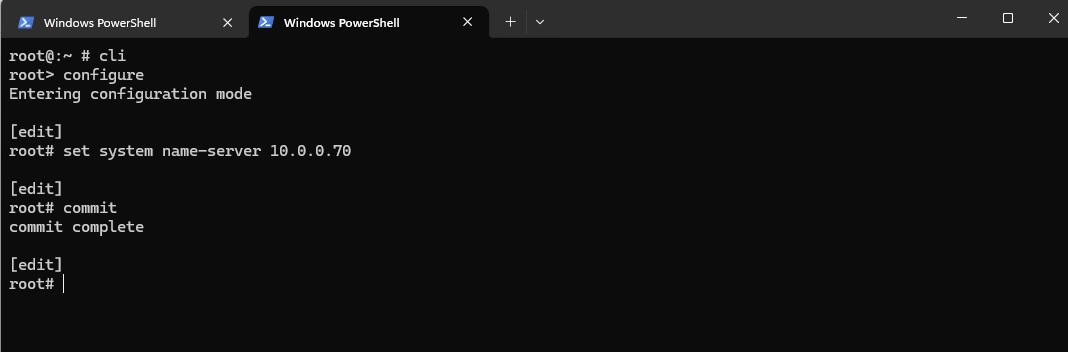
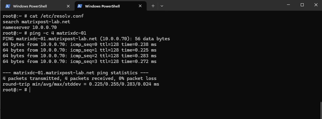
root@:~ # cli
root> configure
root# set system name-server 10.0.0.70
root# commit
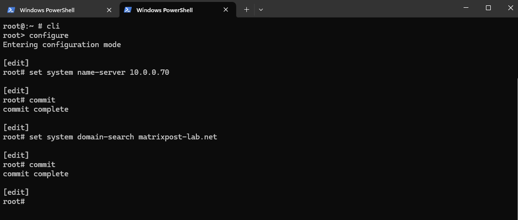
Next we also need to add a DNS search domain to resolve internal hostnames.
root@:~ # cli
root> configure
root# set system domain-search matrixpost-lab.net
root# commit
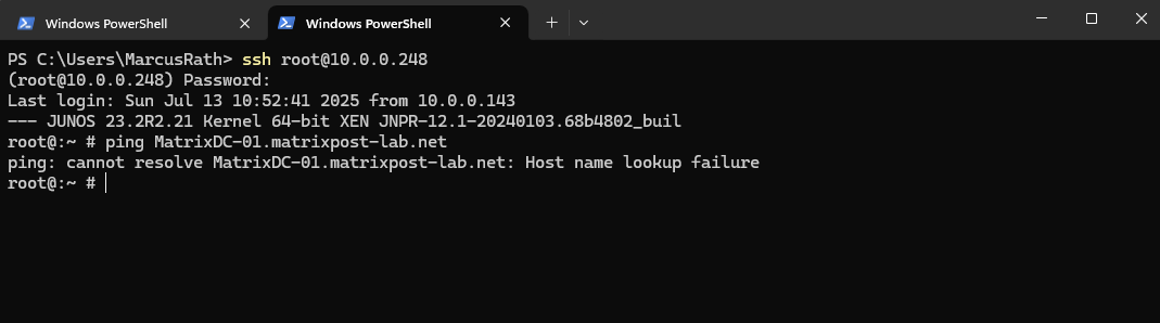
A quick test if name resolution works already, looks good.
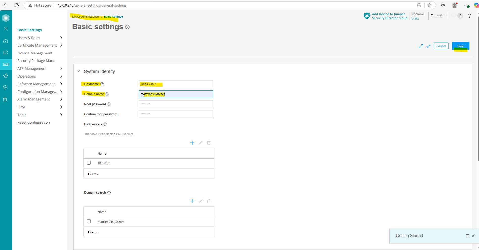
These settings we can also set by using the Web UI.
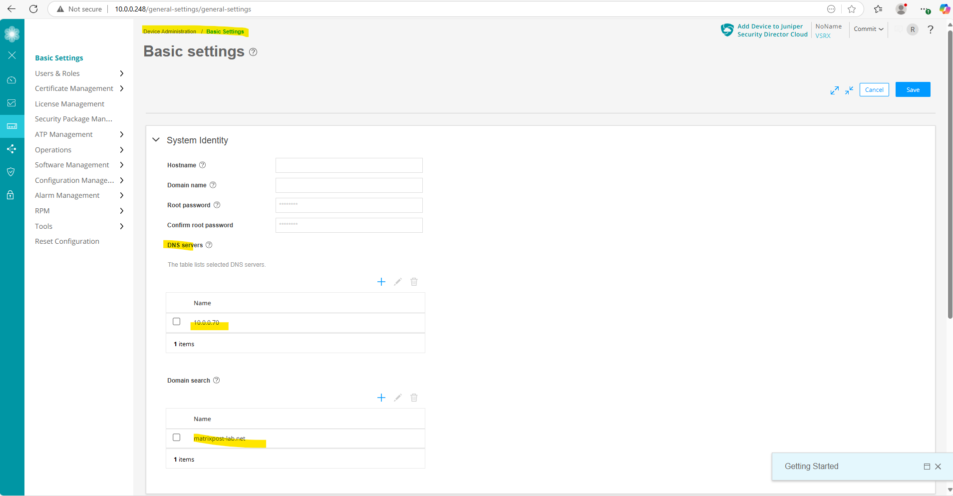
I will also add a hostname and domain for the appliance here.
Next I will set a new static route for outbound Internet access.
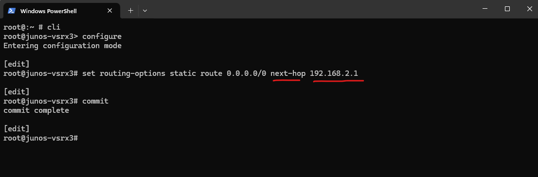
Adding a Static Route for outbound Internet Access
In my case the external interface (ge-0/0/1) of the Juniper appliance is connected to the subnet of my NAT routers (FRITZ!Box in my case) internal interface with the IP address 192.168.2.1, therefore I need to set for the next hop this IP address.
root@:~ # cli
root@junos-vsrx3> configure
root@junos-vsrx3# set routing-options static route 0.0.0.0/0 next-hop 192.168.2.1
We can also create new static routes by using the Web UI under Network -> Routing -> Static Routing.
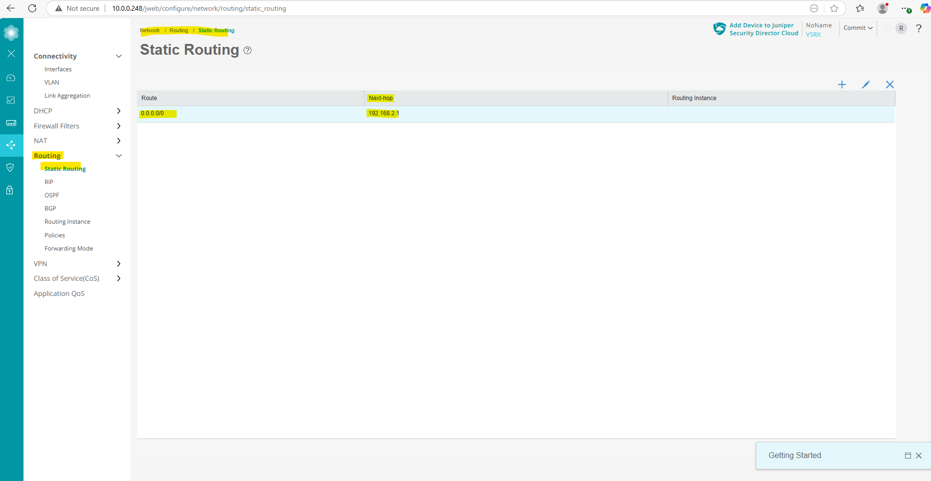
So from now on, the appliance knows the route outbound to the Internet, it must route traffic from inbound connected through the network interfaces (ge-0/0/0) to outbound through the network interfaces (ge-0/0/1) with the next hop 192.168.2.1 (same subnet as the ge-0/0/1 network interface).
To finally allow or deny traffic from inbound to outbound or vice versa and these interfaces ge-0/0/0 and ge-0/0/1, we first need to assign these interfaces to so called security zones.
Configure Security Zones and Zone Addresses
A security zone is a collection of one or more network segments requiring the regulation of inbound and outbound traffic through policies.
Security zones are logical entities to which one or more interfaces are bound. You can define multiple security zones, the exact number of which you determine based on your network needs.
They group together interfaces that share similar security requirements and act as trust boundaries for applying security policies.
An interface for a security zone can be thought of as a doorway through which TCP/IP traffic can pass between that zone and any other zone.
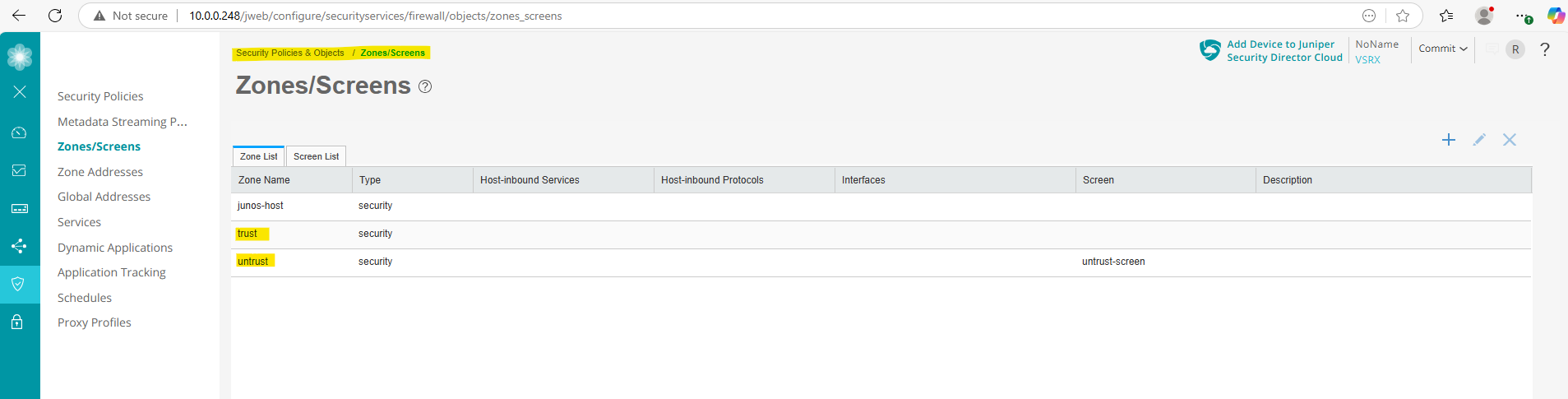
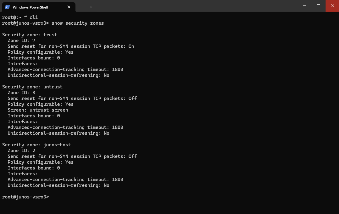
By default we have the following three security zones on the vSRX3.
- junos-host -> represents traffic destined for or originating from the appliance itself
- trust -> Internal network (LAN, management)
- untrust -> Internet-facing (WAN)
Or by using the CLI.
root@:~ # cli
root@junos-vsrx3> show security zones
We can use the security zones later to create new security policies (firewall rules) which finally will allow or deny traffic. These zones we define either as source or destination on the policy.
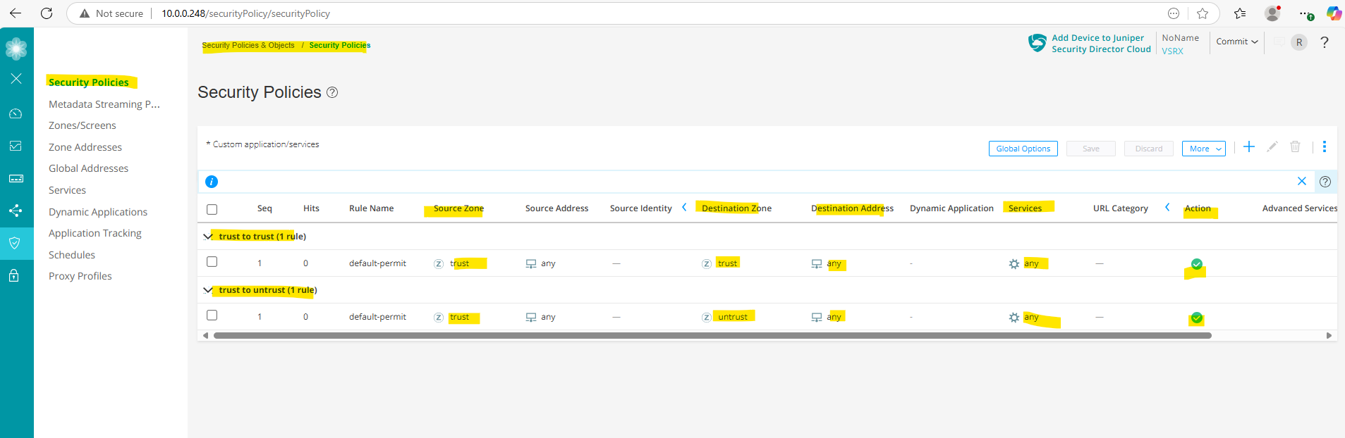
By default the following two policies below are already created and will allow all outbound traffic from the internal trusted zone to the untrusted zone (e.g. DMZ or WAN).
We just need to assign our data interfaces ge-0/0/0 and ge-0/0/1 first to these zones in order our internal trusted hosts can finally access the internet.
Zone addresses are IP address objects that you define and associate with these security zones.
These address objects are used for our security policies to identify source and destination IPs or subnets in a more readable and manageable way.
Assign Interfaces to Security Zones
To assign an interface to a security zone in Juniper vSRX (or any SRX series device) by using the CLI, we can use the set security zones security-zone command as shown below.
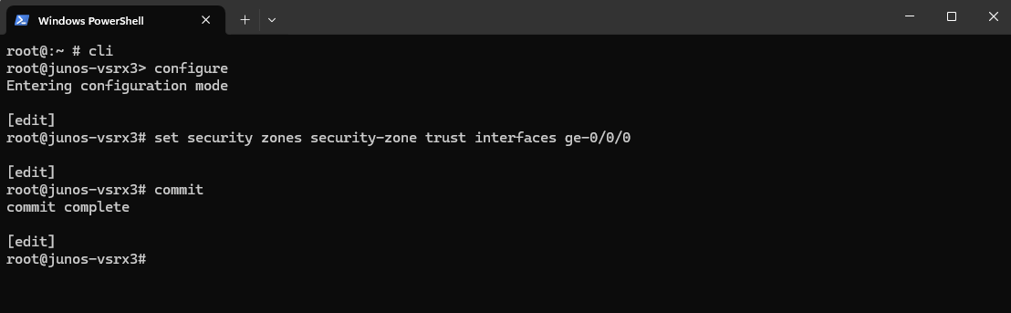
To assign my internal LAN interface ge-0/0/0 to the trust zone:
root@:~ # cli
root@junos-vsrx3> configure
root@junos-vsrx3# set security zones security-zone trust interfaces ge-0/0/0
root@junos-vsrx3# commit
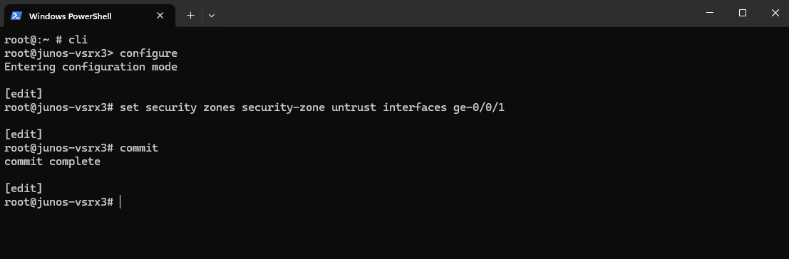
And to assign my WAN (in my case actually DMZ) interface ge-0/0/1 to the untrust zone:
root@:~ # cli
root@junos-vsrx3> configure
root@junos-vsrx3# set security zones security-zone untrust interfaces ge-0/0/1
root@junos-vsrx3# commit
We can already see on the Web UI our interfaces assigned to the desired security zones.
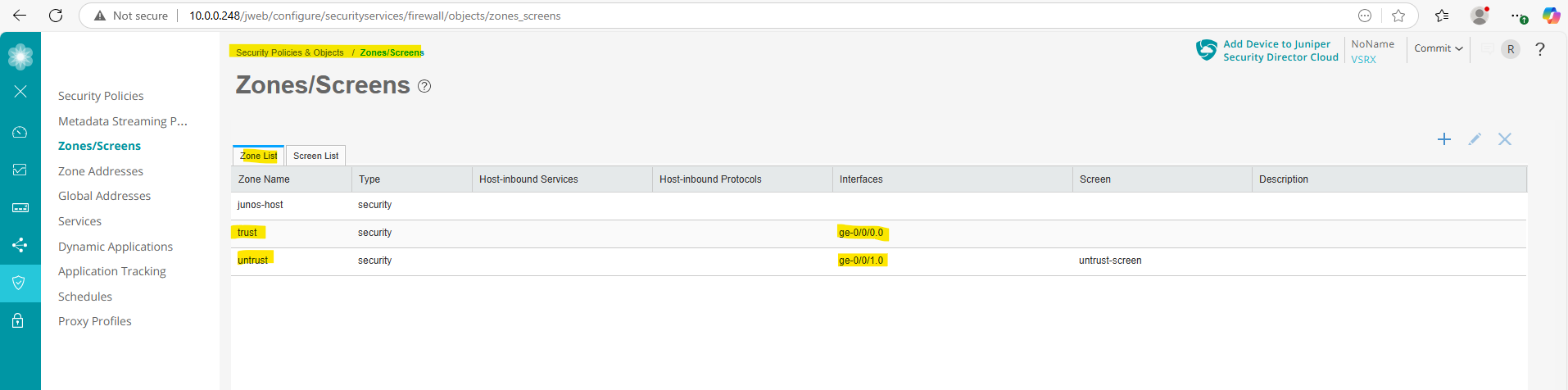
Because of these two default policies shown above, our internal hosts can now already access the internet after assigning the data interfaces to these zones.
Assign Zone Addresses
In Juniper SRX/vSRX, zone addresses are logical groupings of IP addresses (or address sets) that you define within a security zone. These are used in security policies to specify source and destination IPs for matching traffic rules.
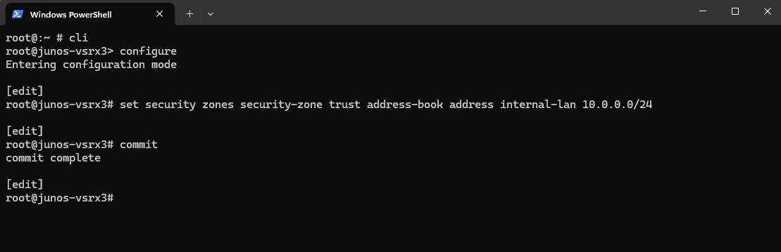
To assign my internal LAN 10.0.0.0/24 to the trust zone in Juniper vSRX (or any SRX running Junos OS), we can use the following command.
The corresponding data interface ge-0/0/0 itself is already assigned to the trust zone.
root@:~ # cli
root@junos-vsrx3> configure
root@junos-vsrx3# set security zones security-zone trust address-book address internal-lan 10.0.0.0/24
commit complete
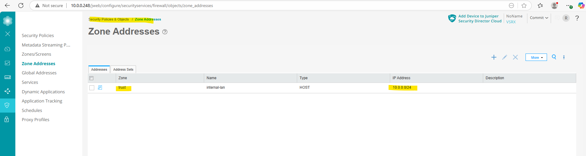
On the Web UI we can see already the new zone address.
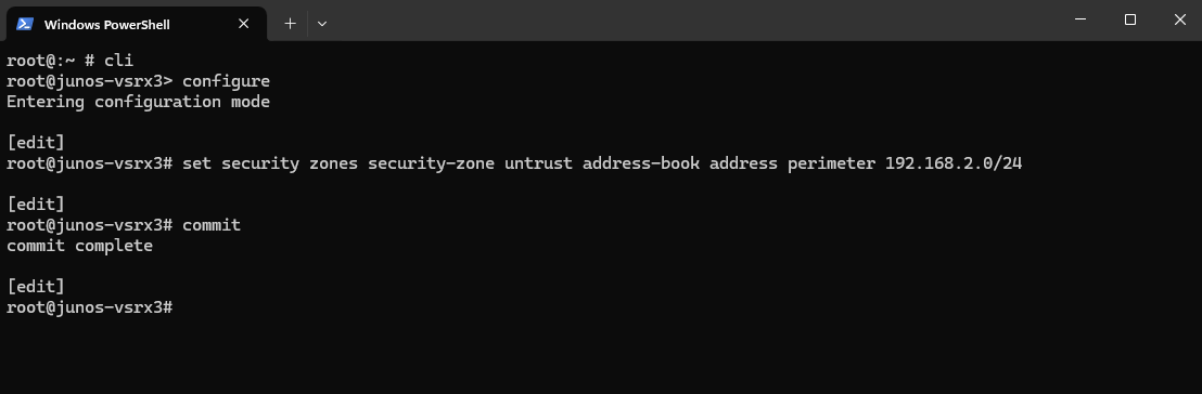
To also assign my DMZ/perimeter 192.168.2.0/24 to the untrust zone in Juniper vSRX (or any SRX running Junos OS), we can use the following command.
root@:~ # cli
root@junos-vsrx3> configure
root@junos-vsrx3# set security zones security-zone untrust address-book address perimeter 192.168.2.0/24
commit complete
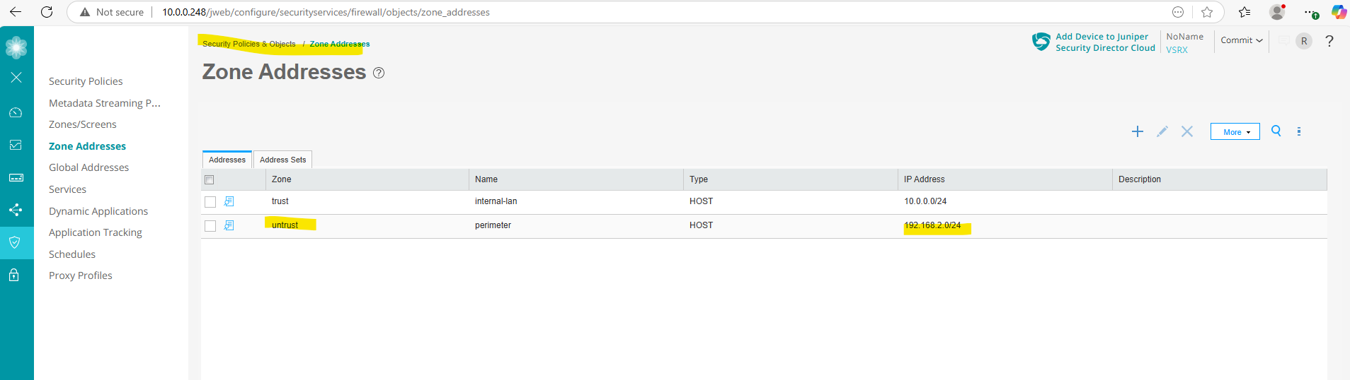
On the Web UI
Configure Security Policies
Security policies enforce rules for transit traffic, in terms of what traffic can pass through the firewall, and the actions that need to take place on traffic as it passes through the firewall.
A security policy is a set of statements that controls traffic from a specified source to a specified destination using a specified service.
A policy permits, denies, or tunnels specified types of traffic unidirectionally between two points.
Actions for traffic matching the specified criteria include permit, deny, reject, log, or count.
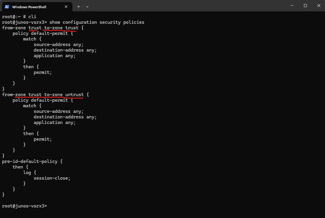
By default the following two security polices already exists as mentioned further above on the Juniper vSRX appliance.
Any traffic between the trust zone is allowed and further all outbound traffic from the trust zone to the untrust zone is also allowed.
We can also display them by using the following command on the CLI.
root@:~ # cli
root@junos-vsrx3> show configuration security policies
Configure Host Inbound Traffic on a Security Zone
In Juniper Junos OS, the Host Inbound Traffic setting for a security zone controls what traffic is allowed to reach the device itself, not traffic that is forwarded (in transit) through the device.
It defines which protocols and services the Juniper device will accept and respond to on interfaces assigned to that security zone.
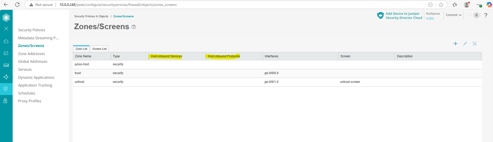
When navigating to Security Policies & Object -> Zones/Screens we can see below that so far no Host-inbound traffic is configured for the existing security zones.
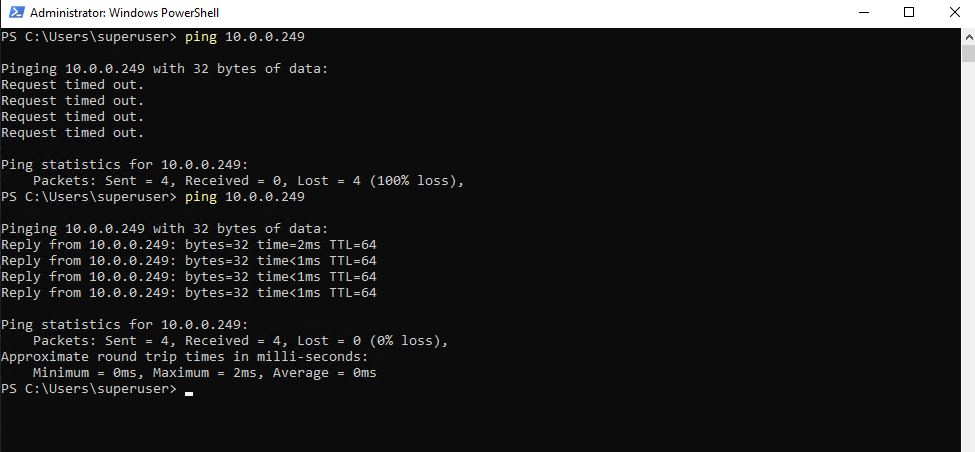
For example if we want to ping the internal interface ge-0/0/0 (in my case IP 10.0.0.249), we first need to allow this traffic (service) on the ge-0/0/0 interface itself.
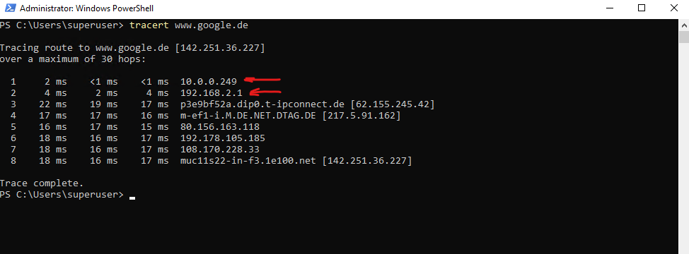
So far just traffic which is routed from the internal trusted zone through this interface (traffic in transit) is allowed like shown here with the tracert command from an internal host outbound to the Internet.
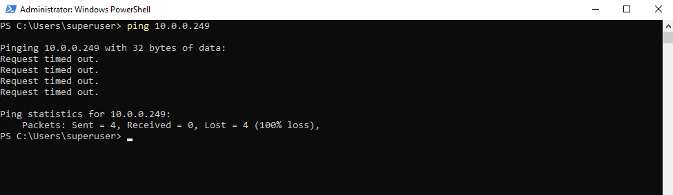
When we now try from the same client to directly ping the internal interface ge-0/0/0 (IP 10.0.0.249), we will run into an Request timed out because so far traffic directly send to this interface (device itself) is not allowed.
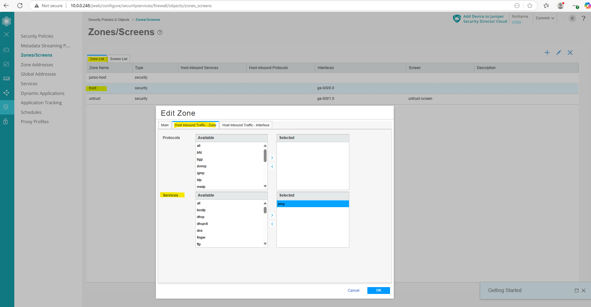
To allow Pings aka ICMP Echo Request and Reply messages directly on the internal interface (ge-0/0/0), we first need to configure this on the security zone, trust blow.
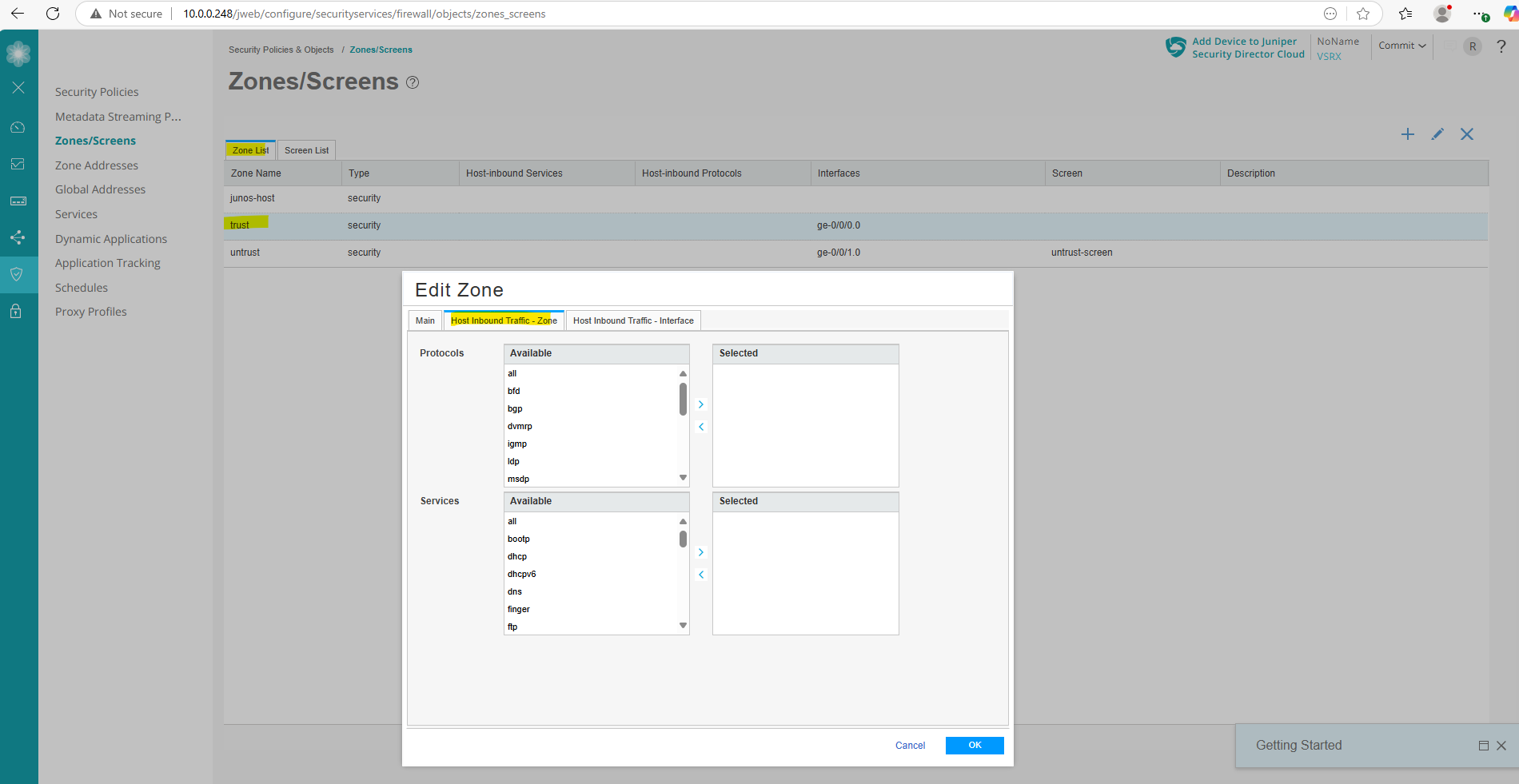
Select ping from the services.
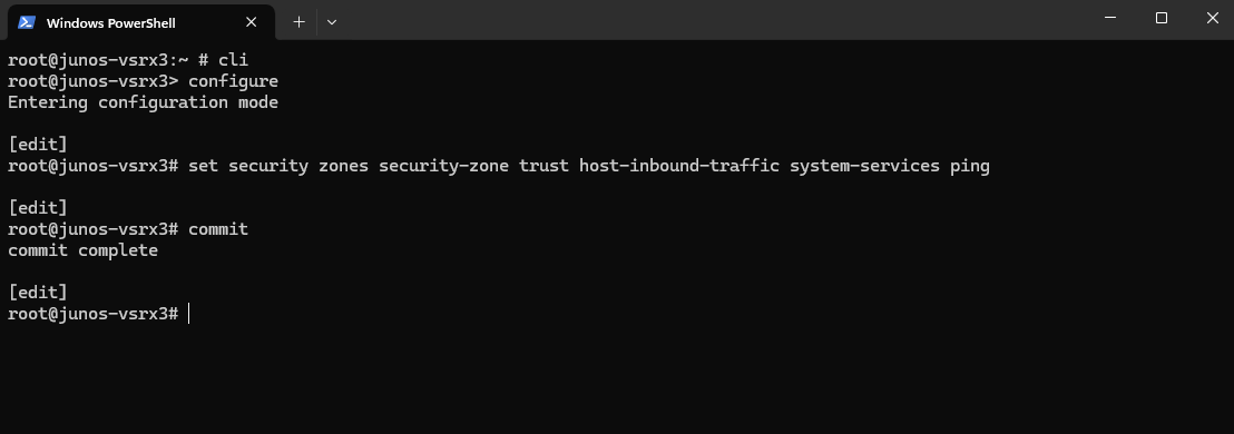
We can also configure this by using the CLI and following command.
root@junos-vsrx3:~ # cli
root@junos-vsrx3> configure
root@junos-vsrx3# set security zones security-zone trust host-inbound-traffic system-services ping
root@junos-vsrx3# commit
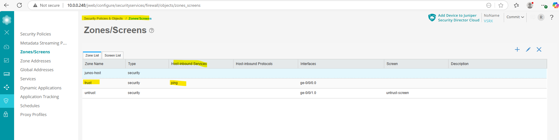
From now on we can also directly ping Junipers “internal” data interface ge-0/0/0 (IP 10.0.0.249).
Configure NAT
Source NAT (SNAT)
SNAT (Source Network Address Translation) is a type of NAT where the source IP address of outgoing packets is changed, typically to a public IP, so that traffic from internal (private) devices can communicate with external networks like the internet.
Juniper vSRX (or any Junos-based firewall) does not configure any NAT rules by default.
In my case as mentioned the appliance sits behind a NAT router (FRITZ!Box) and therefore doesn’t need to perform NAT itself.
In case the appliance is connected directly to the WAN, the external interface should perform Source NAT (SNAT) to hide the internal private IPs behind Junipers public IP assigned on the WAN interface.
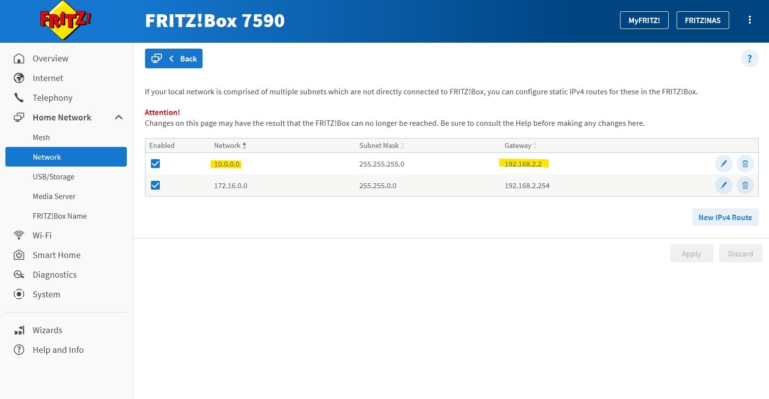
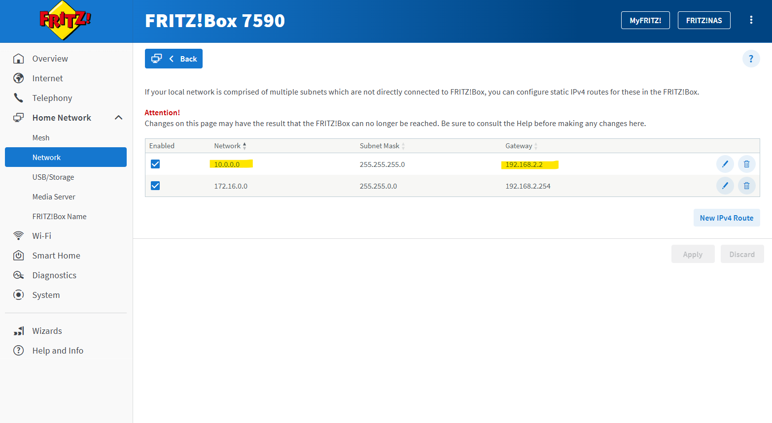
Further my NAT router (FRITZ!Box) does know the route to my internal LAN 10.0.0.0/24 with the next hop 192.168.2.2 (my Juniper appliance and its external interface ge-0/0/1).
In case the NAT router doesn’t known this route, we could also alternatively perform SNAT on Junipers external interface ge-0/0/1 and IP 192.168.2.2 (DMZ in my case) to hide the client IPs from the internal 10.0.0.0/24 subnet behind this IP which is in the same subnet as the NAT routers (FRITZ!Box) internal interface and its IP 192.168.2.1.
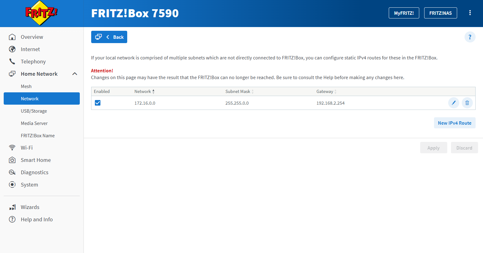
To demonstrate configuring SNAT on the Juniper appliance, I will now remove the static route on my NAT router (FRITZ!Box) for the internal LAN 10.0.0.0/24.
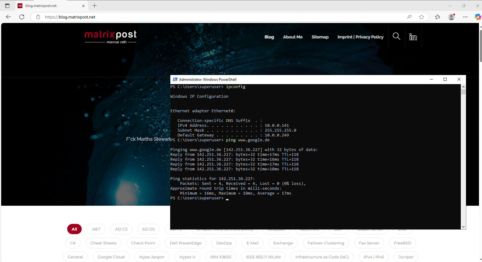
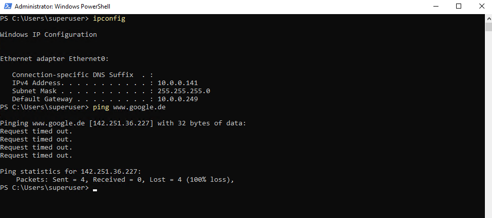
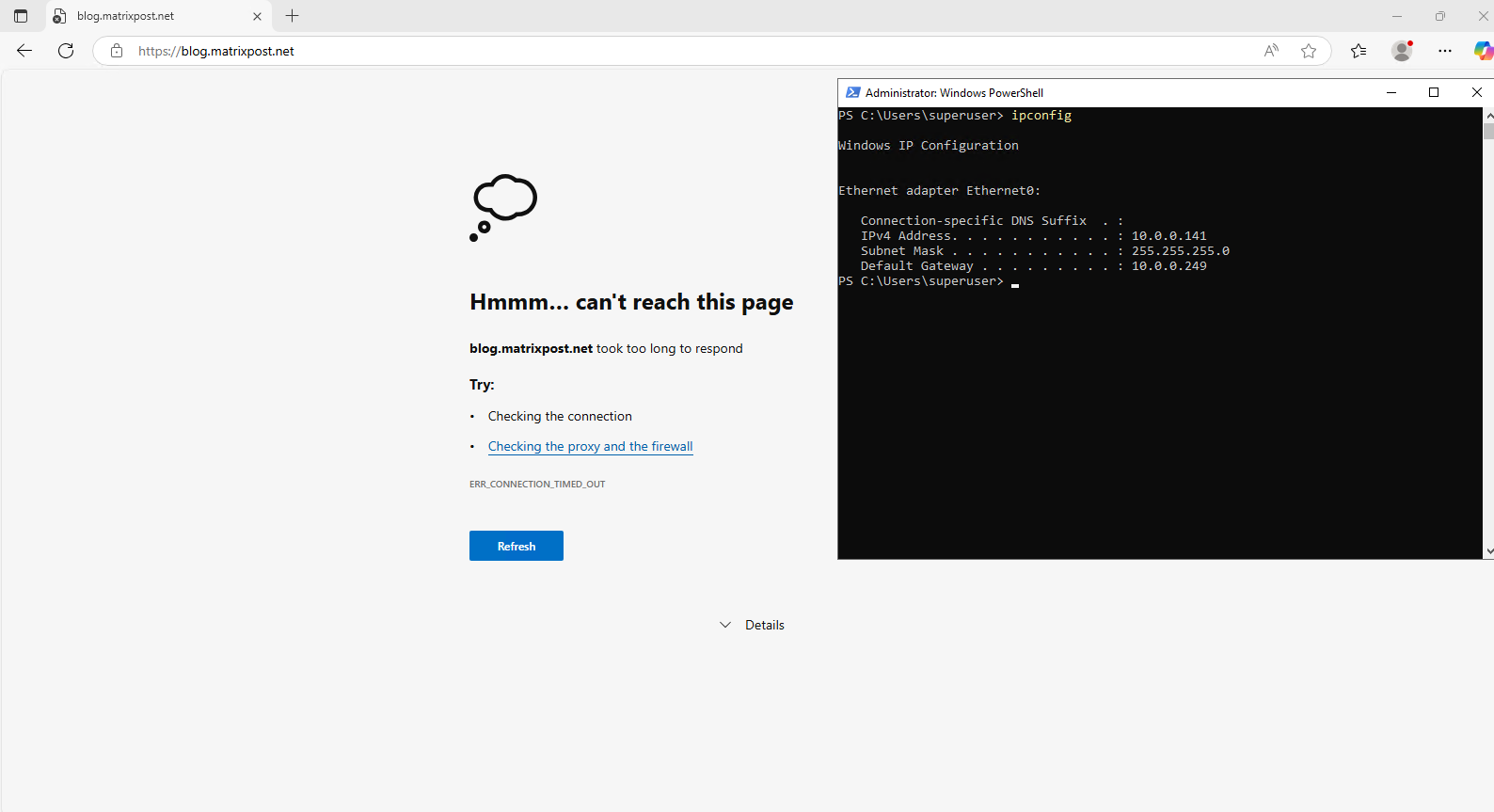
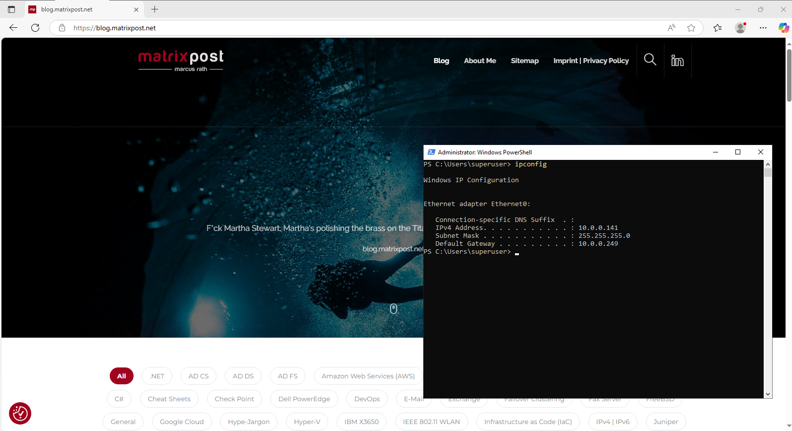
So from now on, when a host from my internal LAN 10.0.0.0/24 want to access services in the Internet, the Juniper appliance will route outbound traffic to my NAT router (FRITZ!Box) but so far doesn’t NAT the clients internal IP address (e.g. 10.0.0.141 below), therefore reply traffic couldn’t send by my NAT router (FRITZ!Box) back to the host as it doesn’t know the route (next hop) to the internal subnet 10.0.0.0/24.
By the way the still existing route to the network 172.16.0.0/16 is my Azure VNet used for the following post https://blog.matrixpost.net/mastering-azure-firewall-forced-tunneling-configuration/.
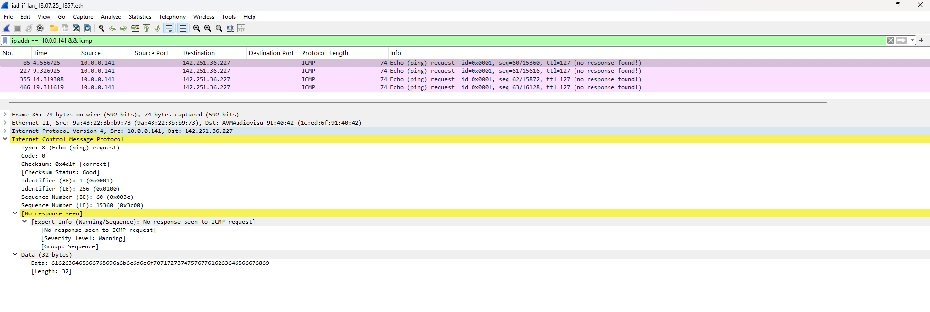
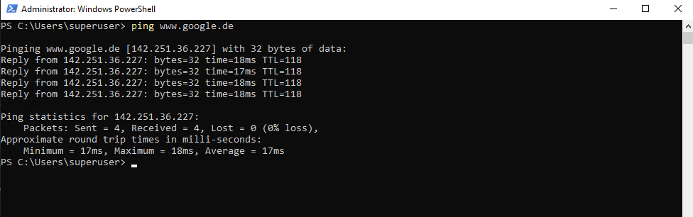
Below I was testing after removing the static route on the NAT router (FRITZ!Box) to ping from a host (IP 10.0.0.141) the Google page.
I will now get a Requested timed out because the NAT router (FRITZ!Box) doesn’t know the route to the internal 10.0.0.0/24 subnet where the host is located.
This traffic captured on the NAT router (FRITZ!Box). About how to capture traffic on FRITZ!Box we will see in the next section below.
We will see just the 4 outbound ICMP Echo Request messages but no ICMP Reply messages.
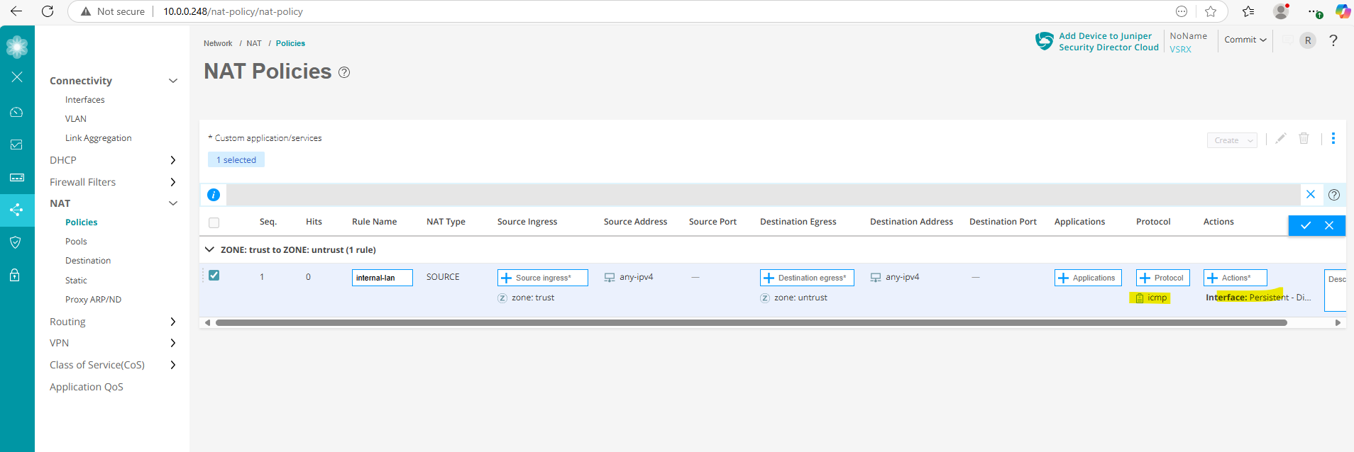
Below I will now create a new SNAT rule to hide all internal client IPs running in the internal 10.0.0.0/24 subnet behind Junipers external ge-0/0/1 interface and its IP 192.168.2.2.
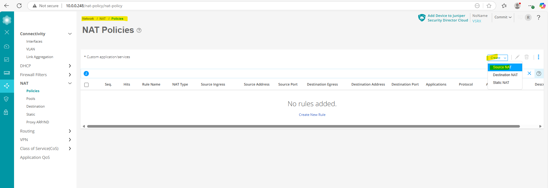
For the protocol so far I will just use ICMP.
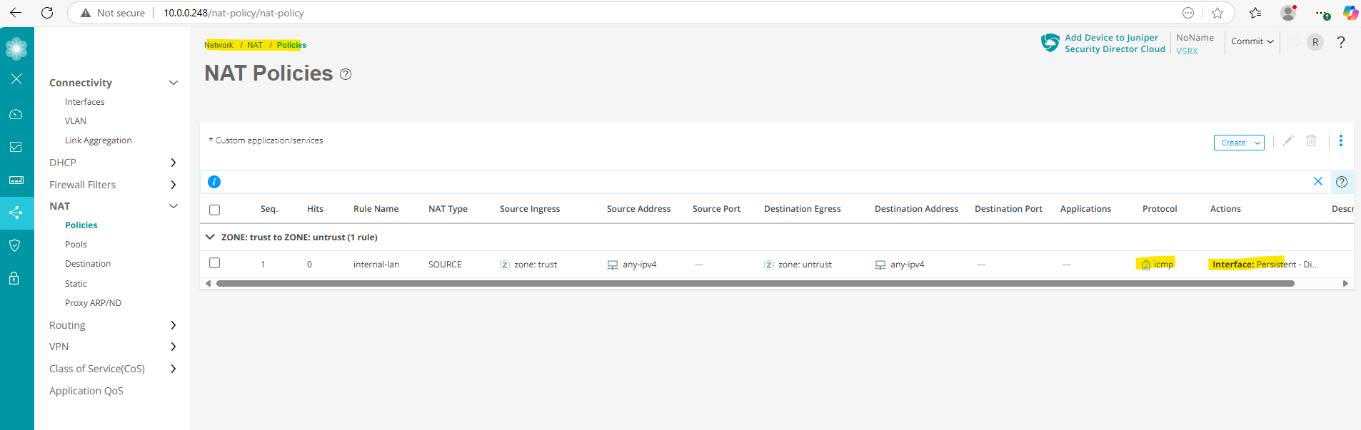
From now on outbound ICMP Echo Request & Reply messages from the internal trust security zone and therefore our subnet 10.0.0.0/24 should work again.
Looks good.
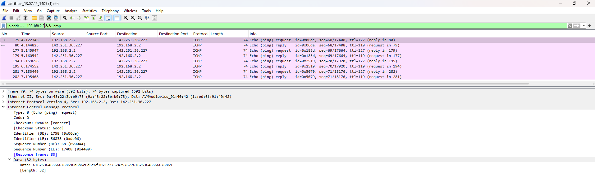
This time when we capture the corresponding traffic on the NAT router (FRITZ!Box), we need to adjust the display filter to filter ICMP packets for Junipers IP address 192.168.2.2 assigned on its external interface ge-0/0/1 as we NAT and hide the clients internal IPs behind.
So far we just NAT the ICMP protocol and therefore HTTP traffic using TCP protocol is not working currently on these internal hosts despite the default outbound policy which actually allows this traffic.
But the same as for the Pings previously, without also NAT HTTP (TCP) traffic my NAT router (FRITZ!Box) doesn’t know the route to send the traffic back to the host.
So I will now adjust my existing rule to also NAT the TCP protocol.
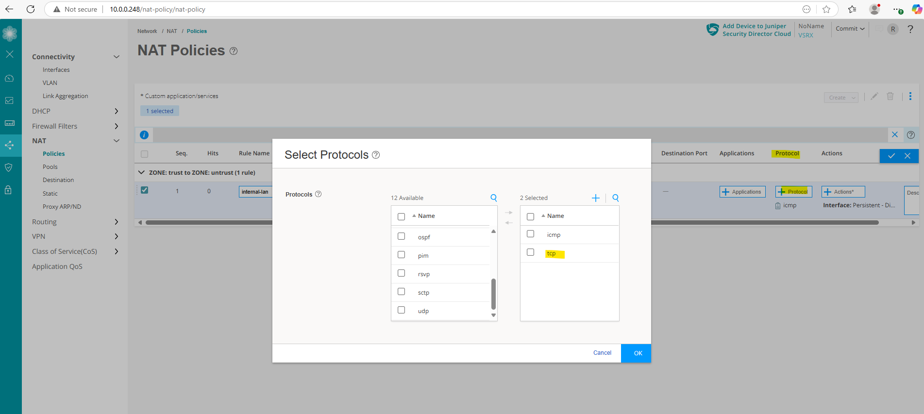
Looks good. HTTP traffic is now also working.
Destination NAT (DNAT)
DNAT (Destination Network Address Translation) modifies the destination IP address of incoming packets, typically to forward traffic from a public IP to a private/internal server to publish internal services like a web server to the internet.
Below I want to show how we can publish a web page running on an internal IIS web server to the internet by using DNAT.
In my case I first need to add again the static route to my Juniper’s external interface ge-0/0/1 and its IP address 192.168.2.2. Further also the existing SNAT rule I have to remove.
Because traffic from external is forwarded by my NAT router (FRITZ!Box), we do not NAT any traffic on the Juniper appliance directly. Nevertheless we need to configure a new DNAT rule to forward traffic to the internal web server but without translating the destination address or destination port number.
This time traffic is initiated from external (internet) and will be forwarded by my NAT router (FRITZ!Box) directly to the internal web server (IP 10.0.0.77) and routed through Juniper’s external interface ge-0/0/1 and its IP address 192.168.2.2 configured as next hop for the 10.0.0.0/24 subnet on the NAT router (FRITZ!Box).
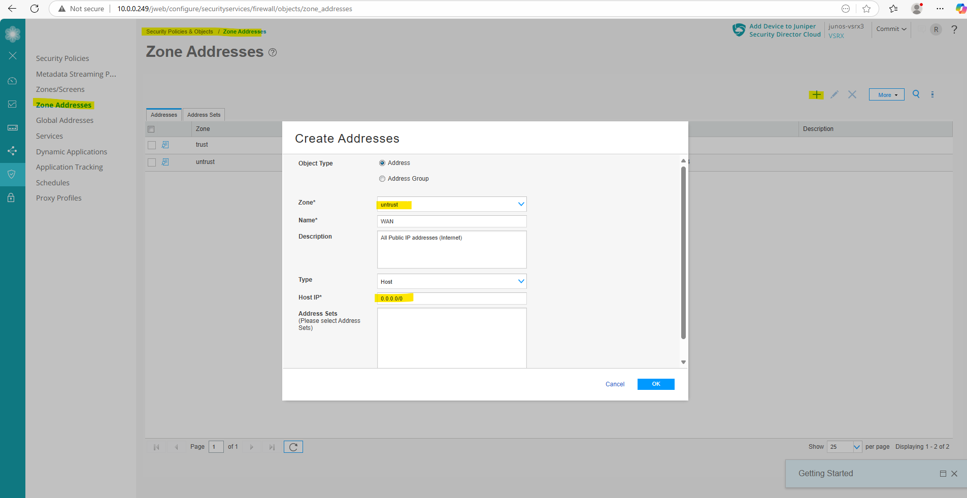
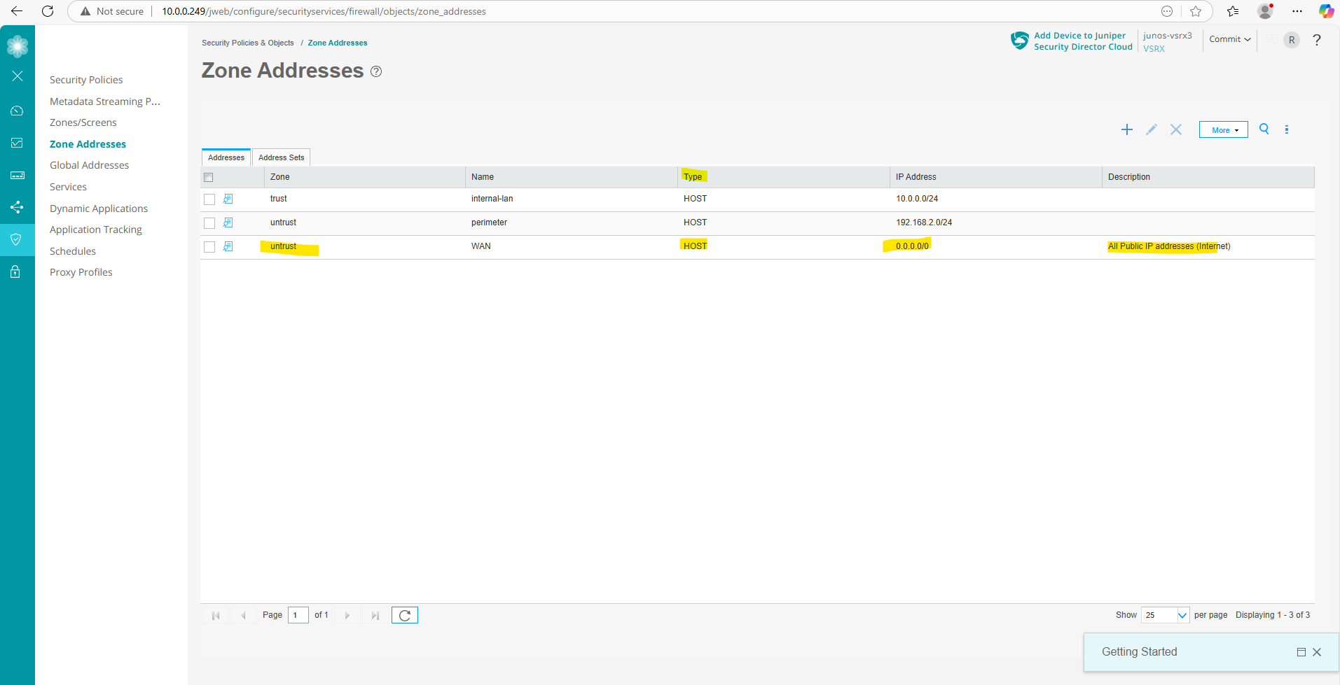
In order to later define and set the source and destination for the new DNAT rule, I will first define and create the source (Internet 0.0.0.0/0) and destination (web server IP 10.0.0.77) as new zone addresses.
Under Security Policies & Objects -> Zone Addresses click on the plus icon to add a new address.
For the zone I will select untrust, for the type Host (we can also define here a network address/space in CIDR format) with the address 0.0.0.0/0 for all IPv4 addresses finally.
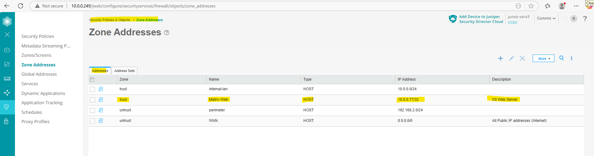
Next I will add the web server as new zone address with the type host and the IP address 10.0.0.077/32.
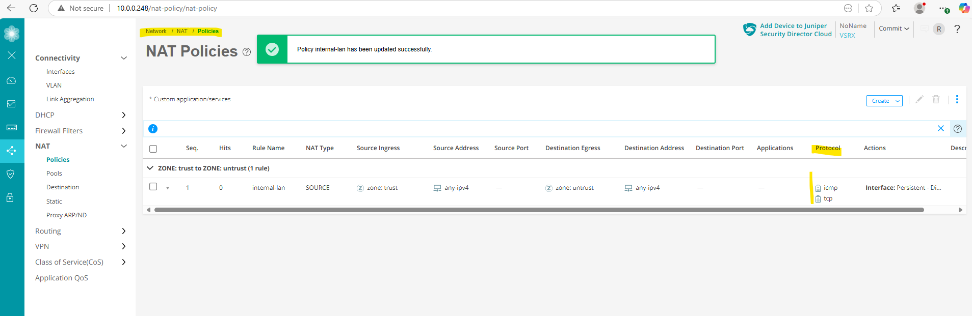
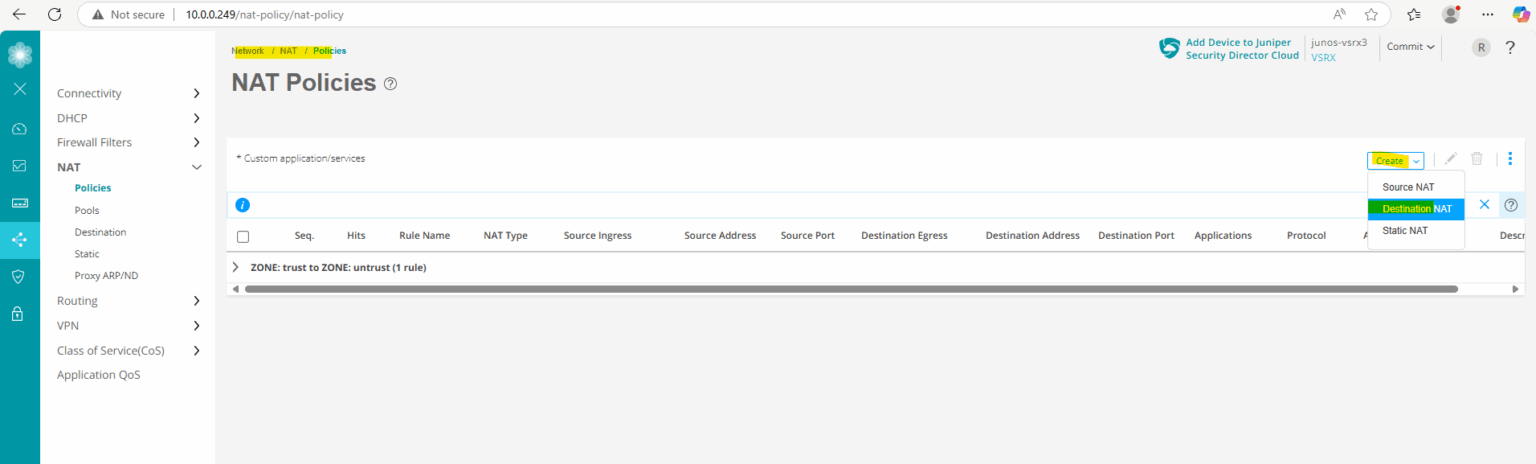
We can now add under Network -> NAT -> Policies a new Destination NAT rule to finally forward the traffic to the internal web server.
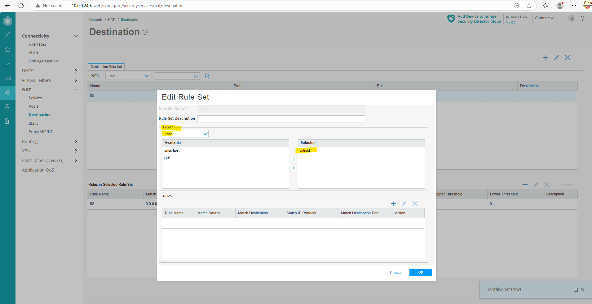
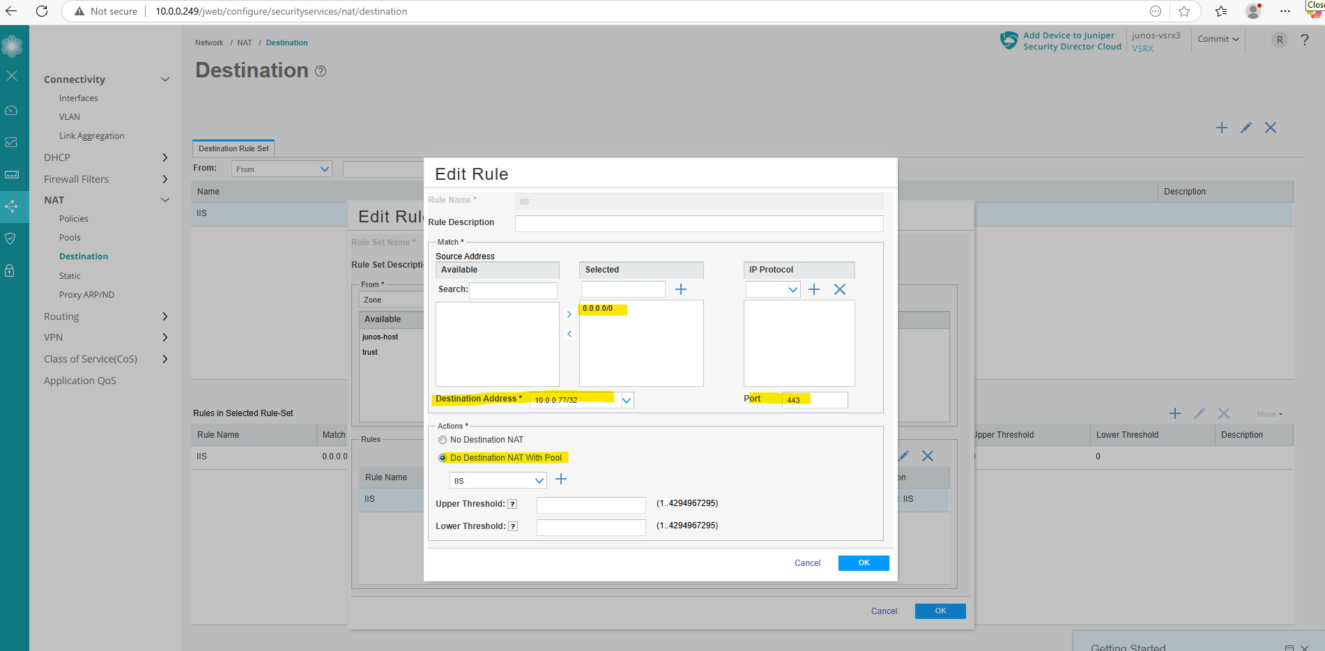
First we create a new destination rule set, under From select Zone and adding the untrust zone. Next click on the plus icon to also add a new rule.
Under Source Address enter 0.0.0.0/0 for all IPv4 addresses in the selected field and click on the plus icon. Further enter the destination IP address of the internal web server, here 10.0.0.77/32 and the port number under which the page is listening, 443.
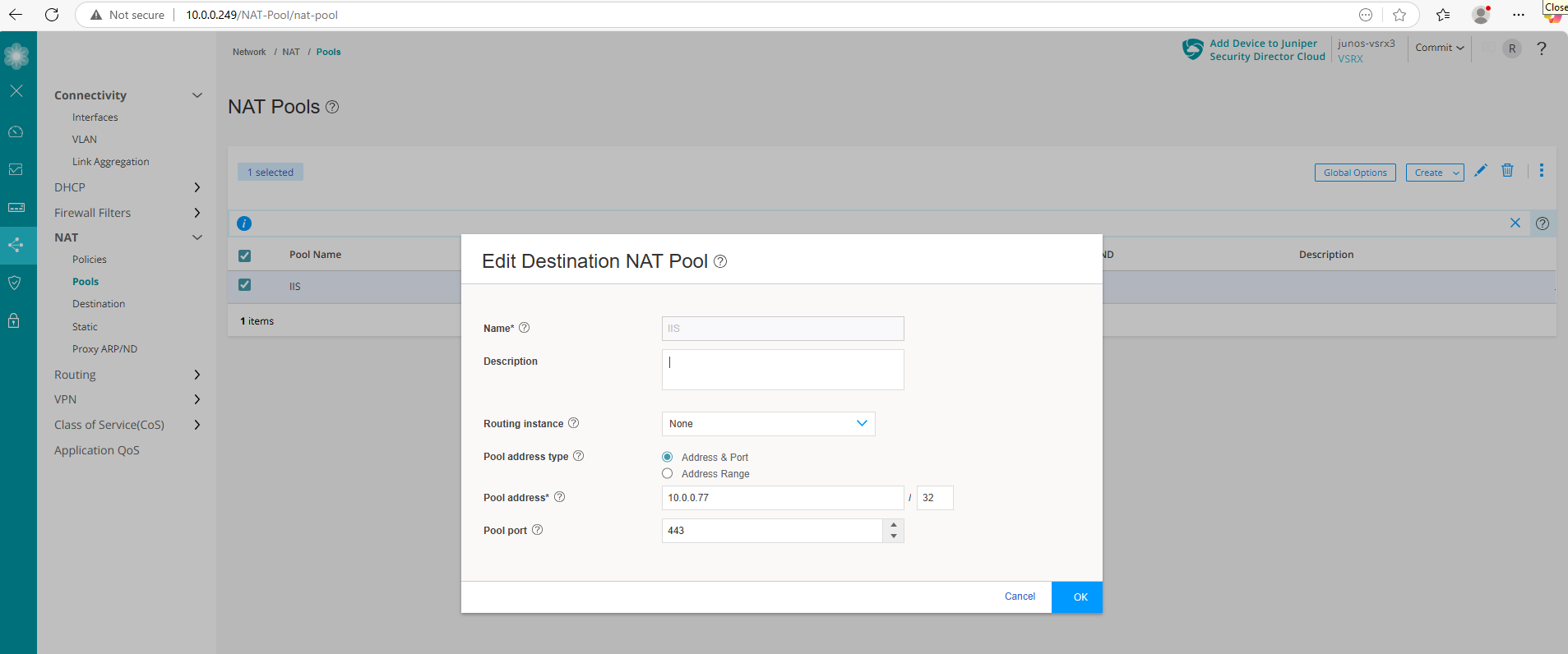
Under Actions select Do Destination NAT with Pool and click on the plus icon to create the destination pool which finally will include the internal web server. In my case I had already created this pool and can just select it.
You can also create the destination pool directly under Network -> NAT -> Pools.
Finally it will looks like.
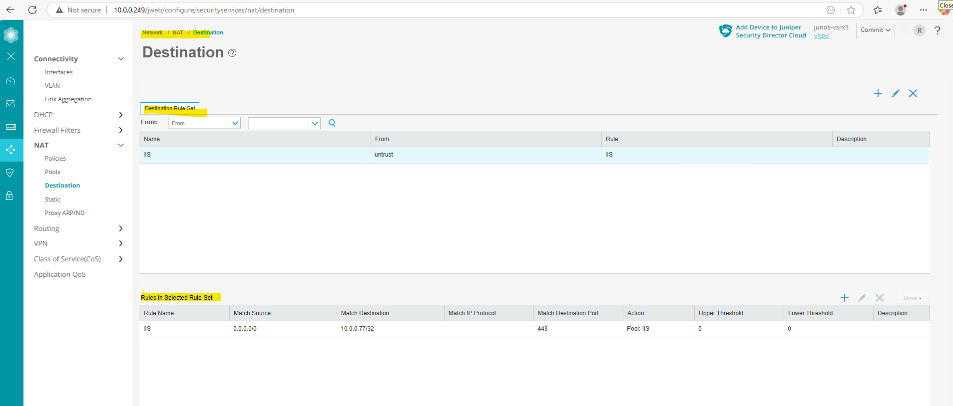
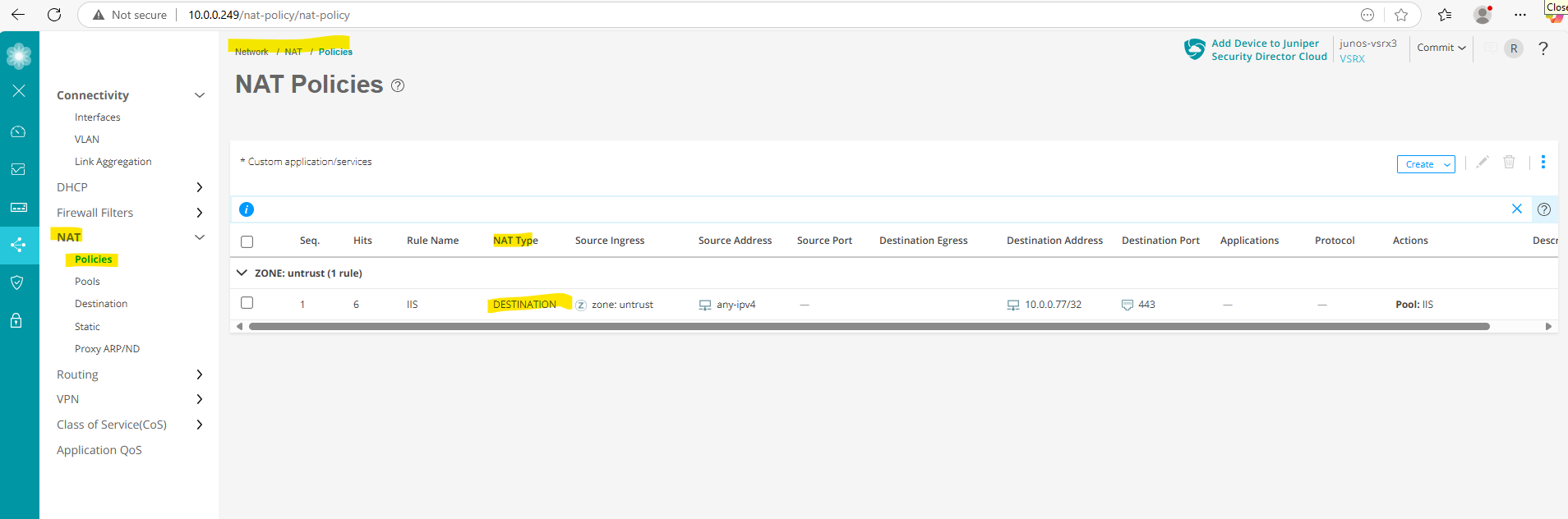
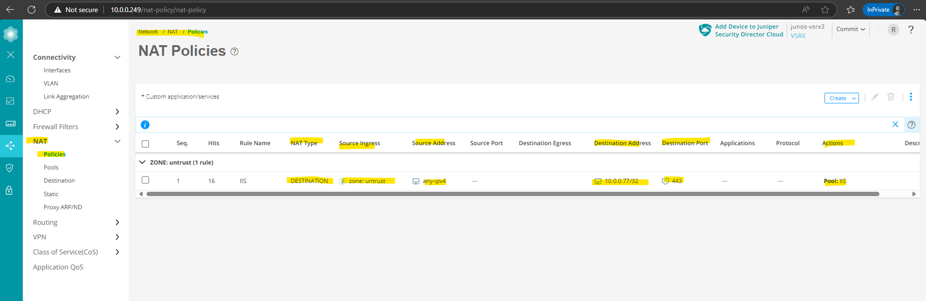
The new destination NAT rule we can also see under Network -> NAT -> Policies.
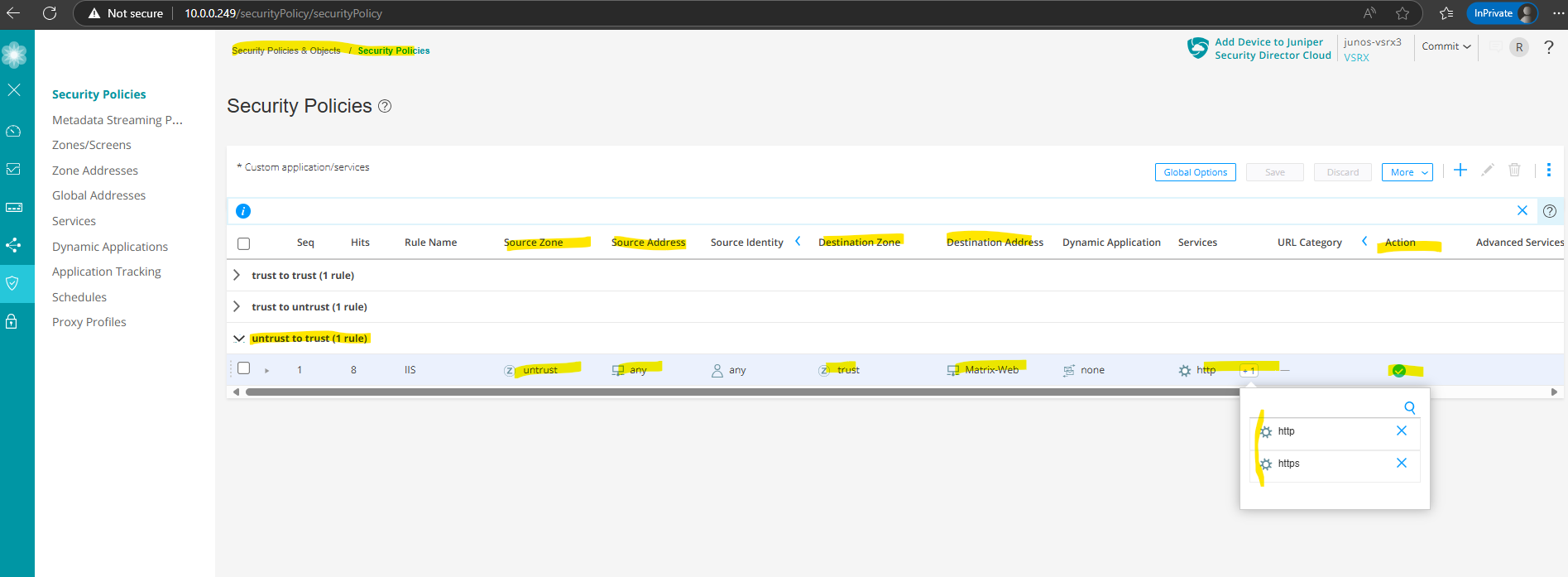
Finally we also need to allow traffic coming from external and be routed directly to the internal web server. Therefore we need to create a new security policy under Security Policies & Objects ->
Security Policies.
Click on the plus icon to create a new security policy.
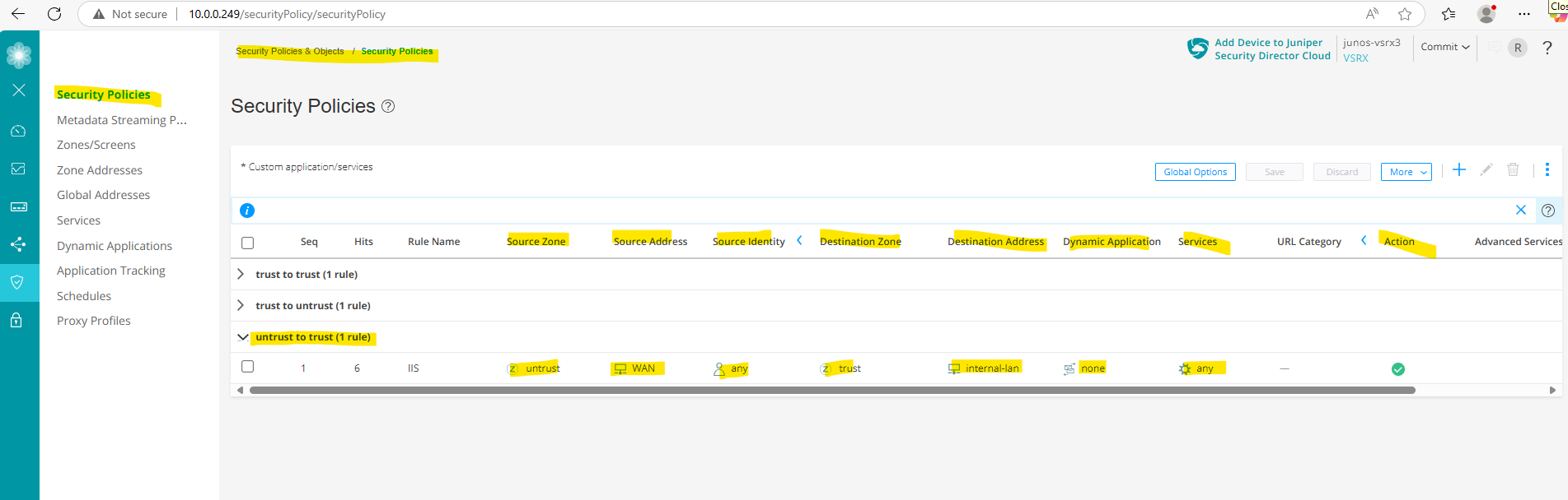
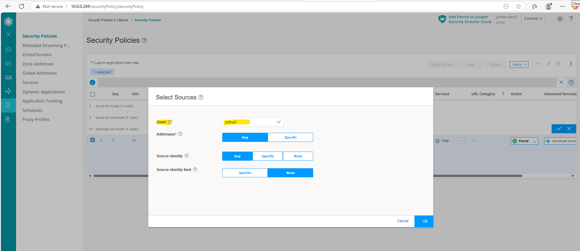
For the source I was selecting the zone untrust which also includes our previously created zone address 0.0.0.0/0 for all IPv4 addresses. For source identity I will select any.
Source identity identifies users and roles to be used as match criteria for a policy.
Any -> Any user or role, as well as the keywords authenticated-user, unauthenticated-user, and unknown-user.
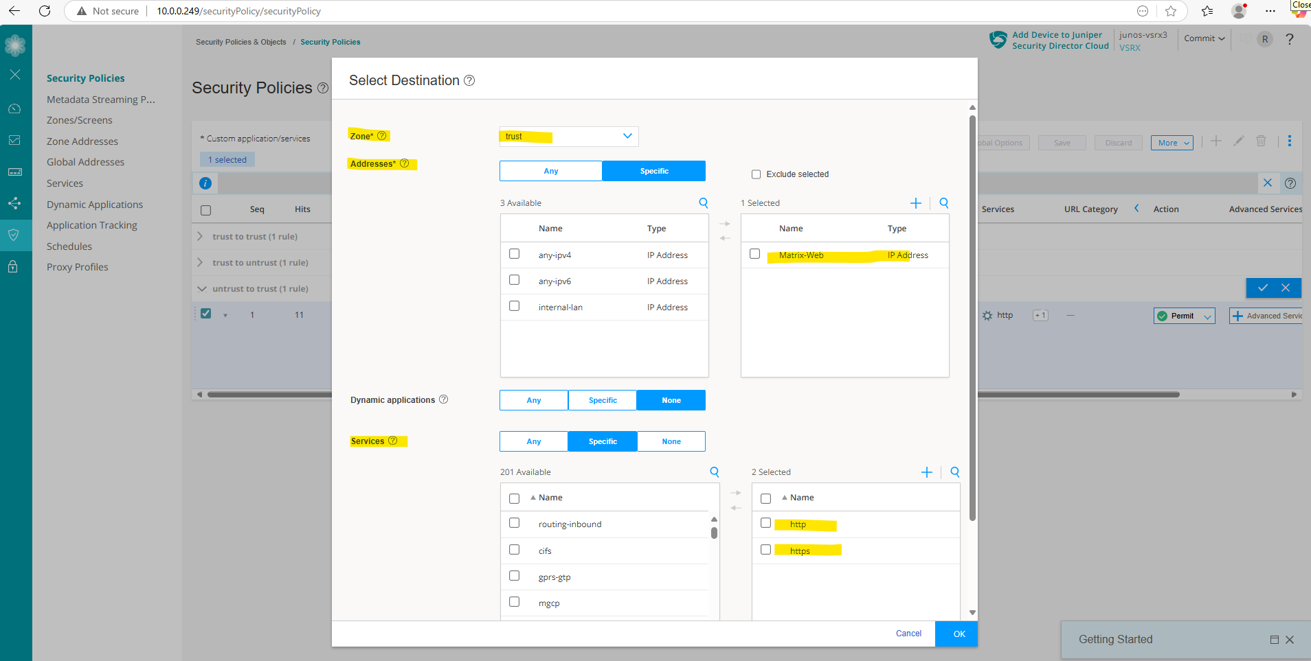
For the destination I will select the zone trust and the previously created zone address which defines the internal web server IP address.
Further for the services to match the rule I will select http and https. This finally will allow http access which is eventually forwarded directly on the web server to https. If configured we also need to add a second DNAT rule with port number 80 for http.
Under Action we will select permit to allow the traffic finally.
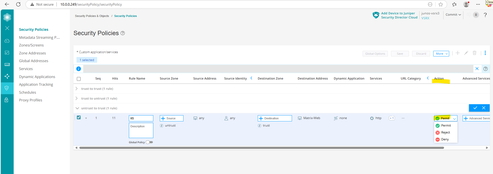
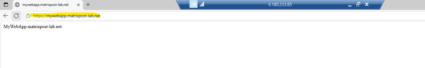
From now on accessing the internal web page from the WAN should work.
Looks good, a quick check from my external Azure VM with the public IP address 4.180.233.85.
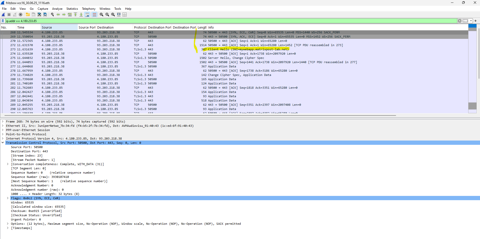
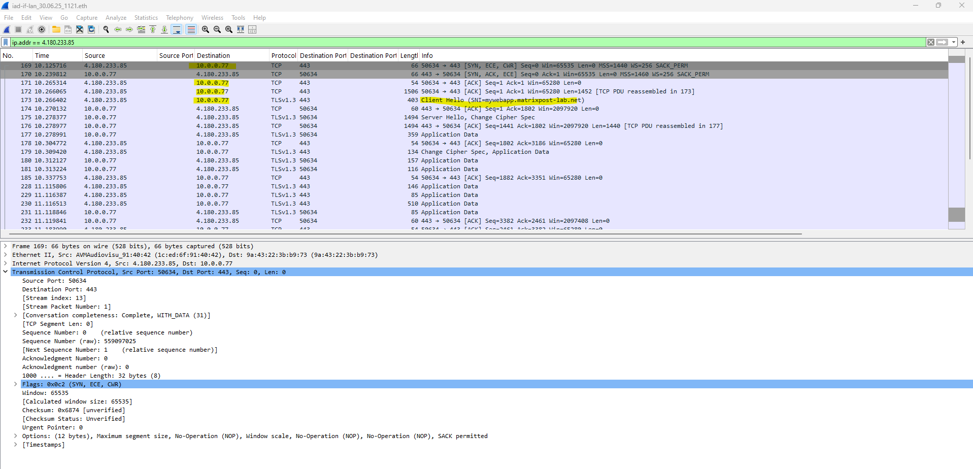
Traffic captured on my NAT routers (FRITZ!Box) external interface connected to the internet.
Here you can first see the TCP 3-Way Handshake (SYN source, SYN ACK destination, ACK souce) between the external Azure VM (IP 4.180.233.85) and my NAT router (FRITZ!Box) on its external interface and temporary assigned public IP address 93.203.218.38.
Traffic captured on my NAT routers (FRITZ!Box) inter LAN interface (IP 192.168.2.1) connected to perimeter subnet 192.168.2.0/24.
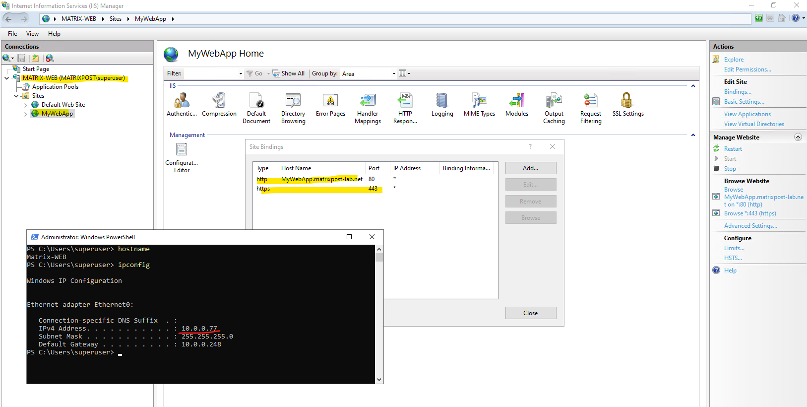
Here you can see that my NAT routers (FRITZ!Box) is forwarding the incoming HTTP request directly to my internal IIS web server with the IP 10.0.0.77.
Here you can see the web page configured on the internal IIS web server 10.0.0.77.
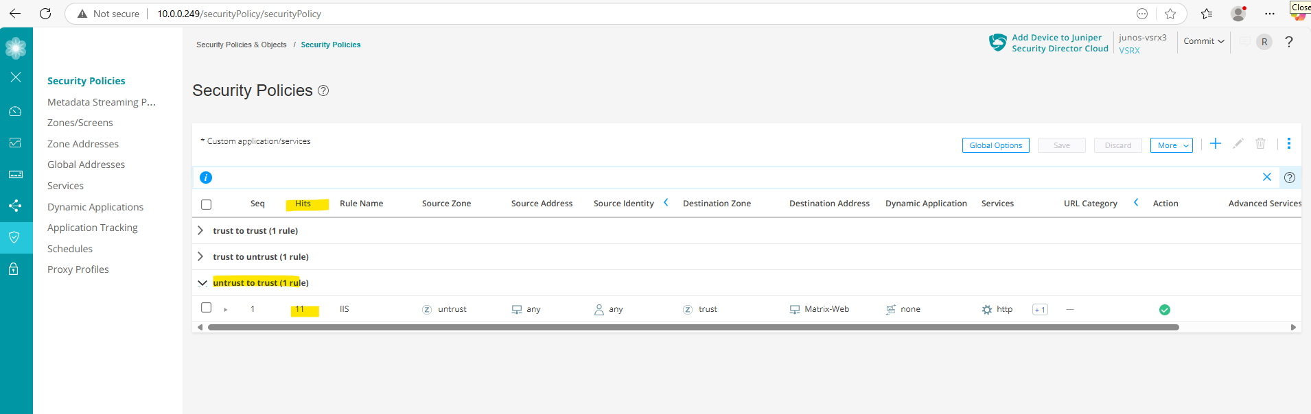
Each time when a security policy matches traffic and will be processed it will increase its Hits as shown below.
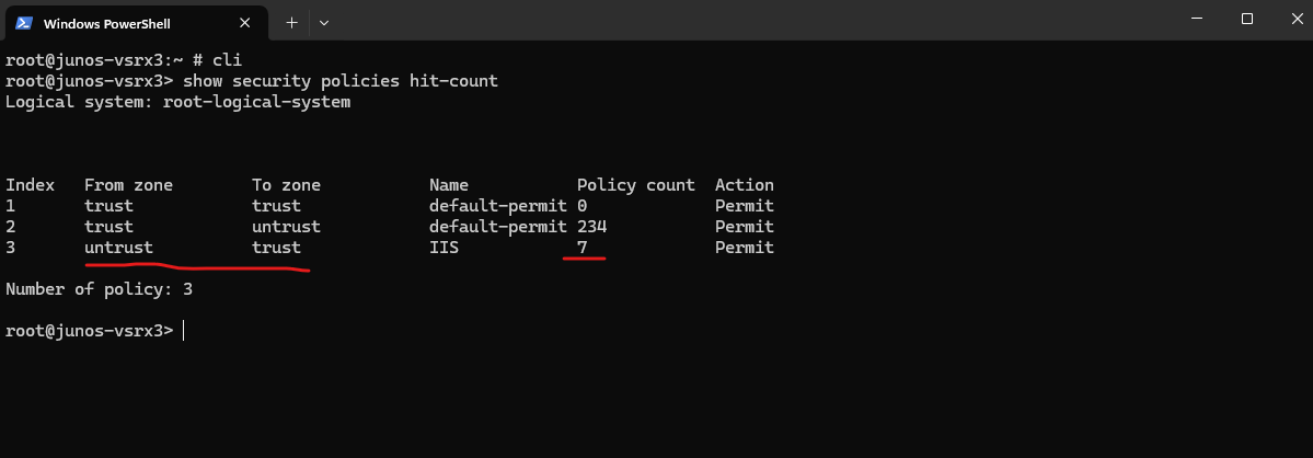
We can also use the CLI and following command to determine the Hits.
root@junos-vsrx3:~ # cli
root@junos-vsrx3> show security policies hit-count
Monitoring Logs
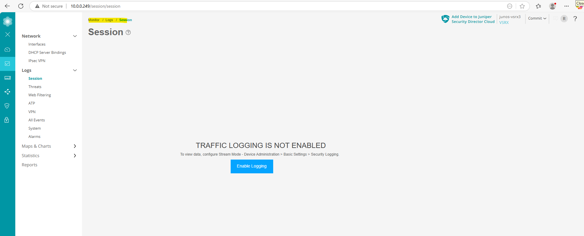
Enable Logging in general
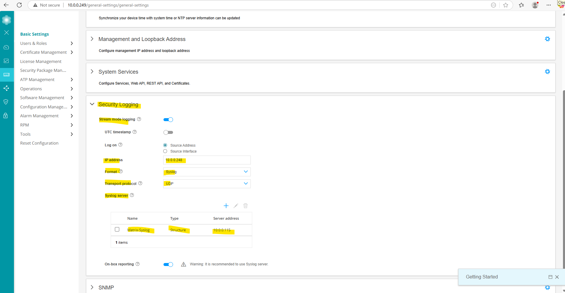
To enable/disable security event logging on the Juniper appliance, we need to navigate to Device Administration -> Basic Settings -> Security Logging or directly under Monitor -> Logs -> Session click on the button below.
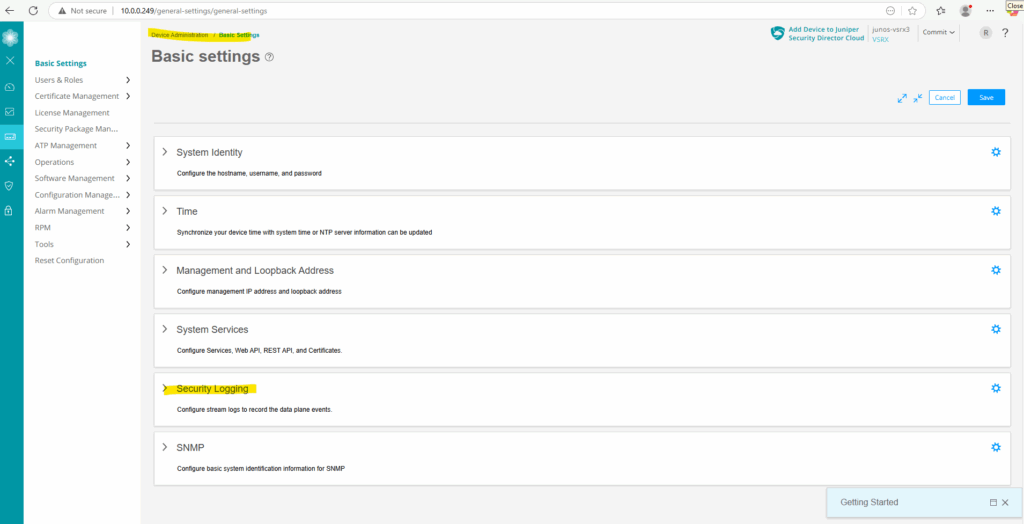
Click on Device Administration -> Basic Settings -> Security Logging.
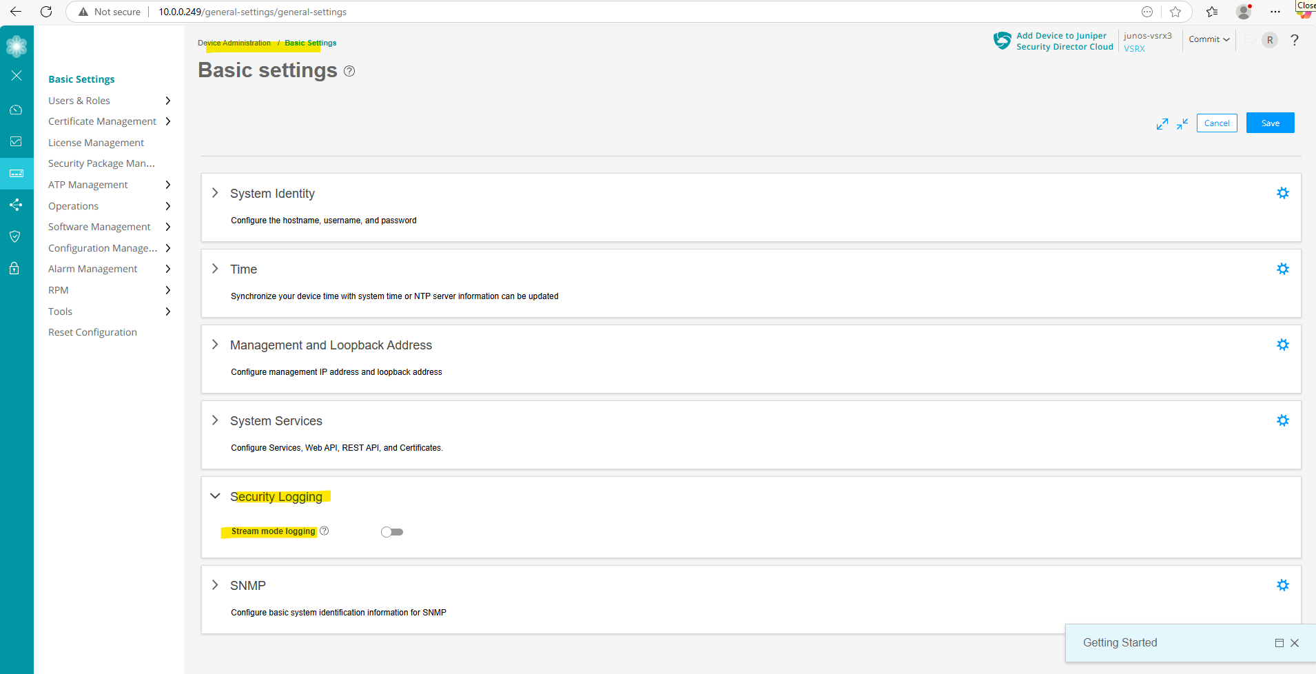
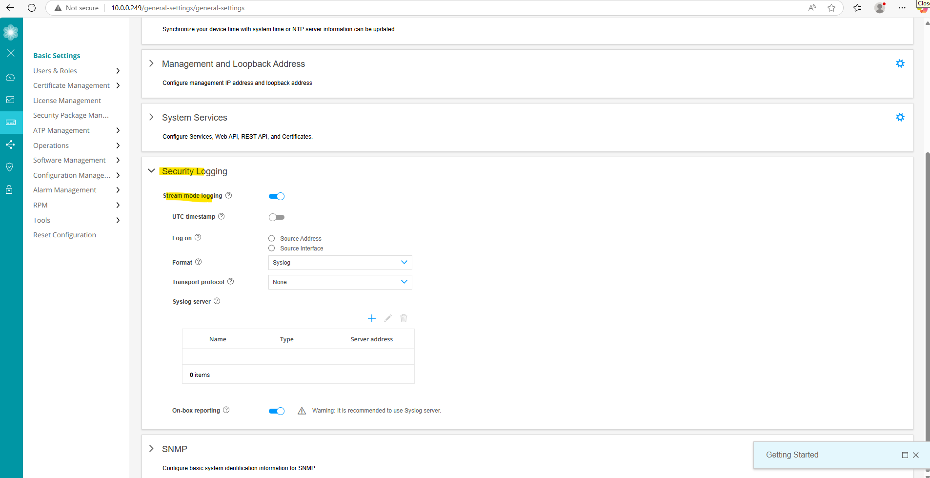
Toggle on Stream mode logging.
Stream logs generated in the data plane are streamed out of a revenue traffic port directly to a remote server.
We can also configure below a remote syslog server which will receive log messages by the Juniper appliance, to just enable them locally we can leave the rest blank and click on Save.
Below I was also adding a remote syslog server named Matrix-Syslog to collect log messages centrally in my lab environment.
About how to set up a syslog-ng server you can also read my following post.
Enable Traffic Session Logging
As we enabled logging in general on the appliance, we can now also enable logging to record traffic sessions that pass through the firewall. These logs are extremely useful for troubleshooting, monitoring network activity, and security auditing.
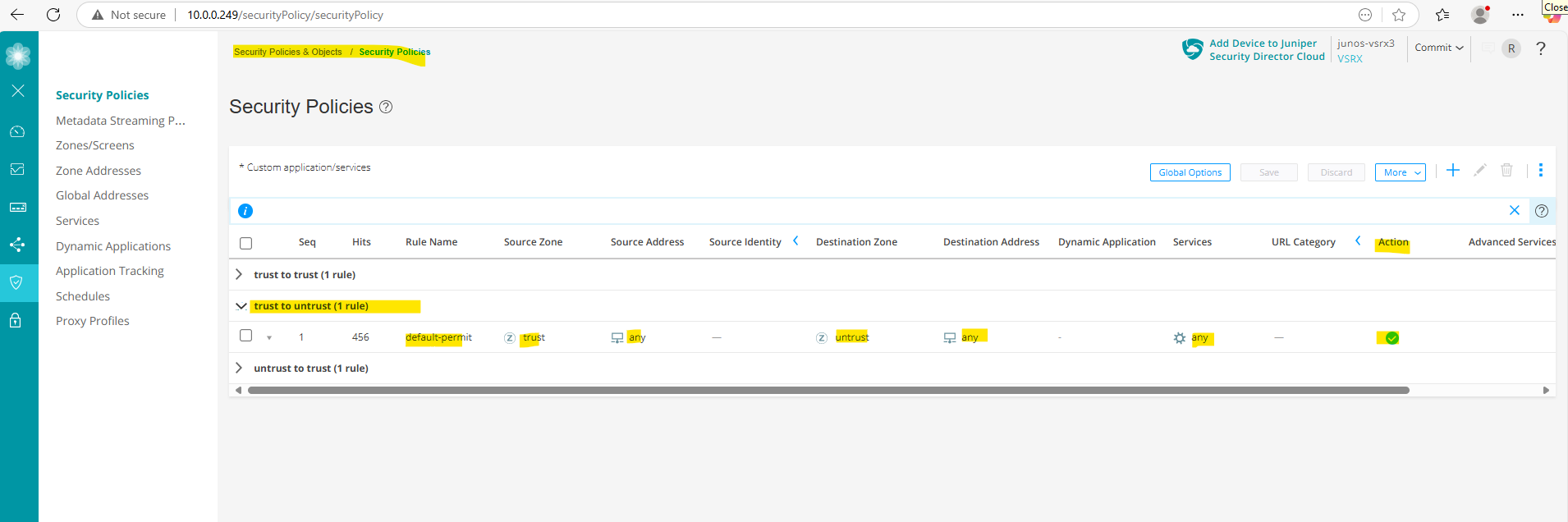
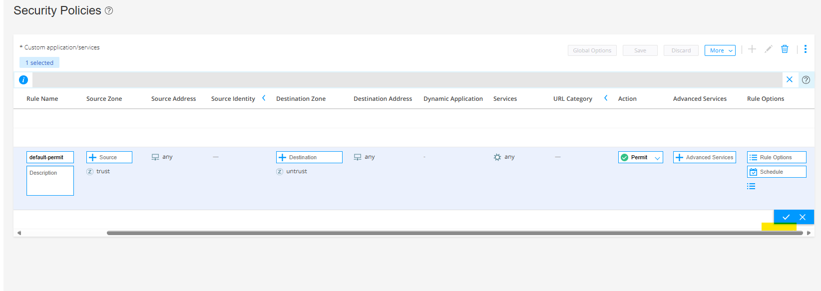
To enable them navigate on the Web UI to Security Policies & Objects -> Security Policy -> select the desired Policy you want to enable logging for.
Below for example I want to enable the session logs for the policy which allows all outbound traffic from the internal (trusted) LAN to WAN (untrusted).
Click under Rule Options on the menu icon as shown below.
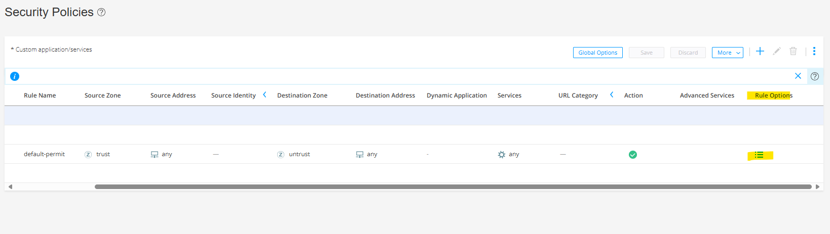
Click on Rule Options.

Enable all three options for Session initiate, Session close and Count.
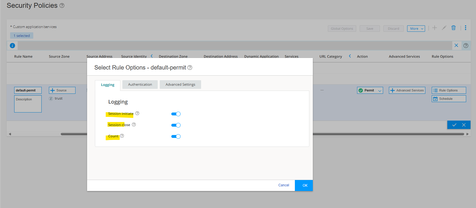
Click on the check icon.
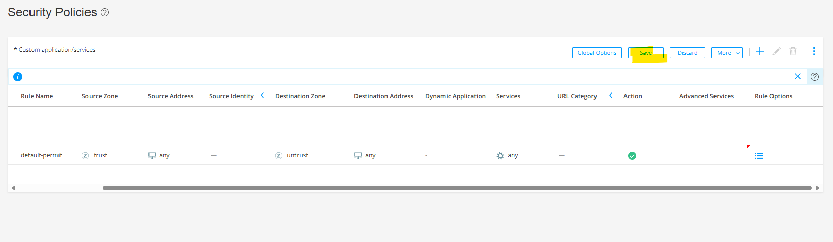
Click on Save.
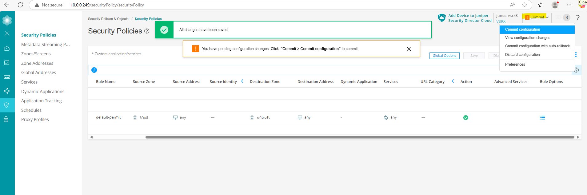
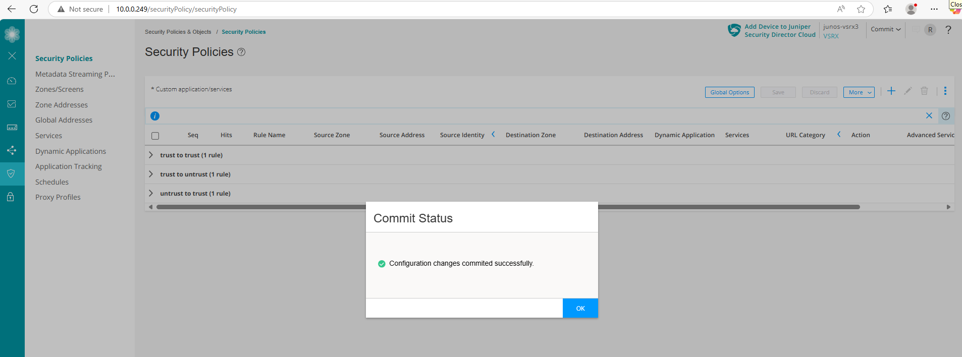
Finally commit the configuration.
Enable Traffic Session Logging
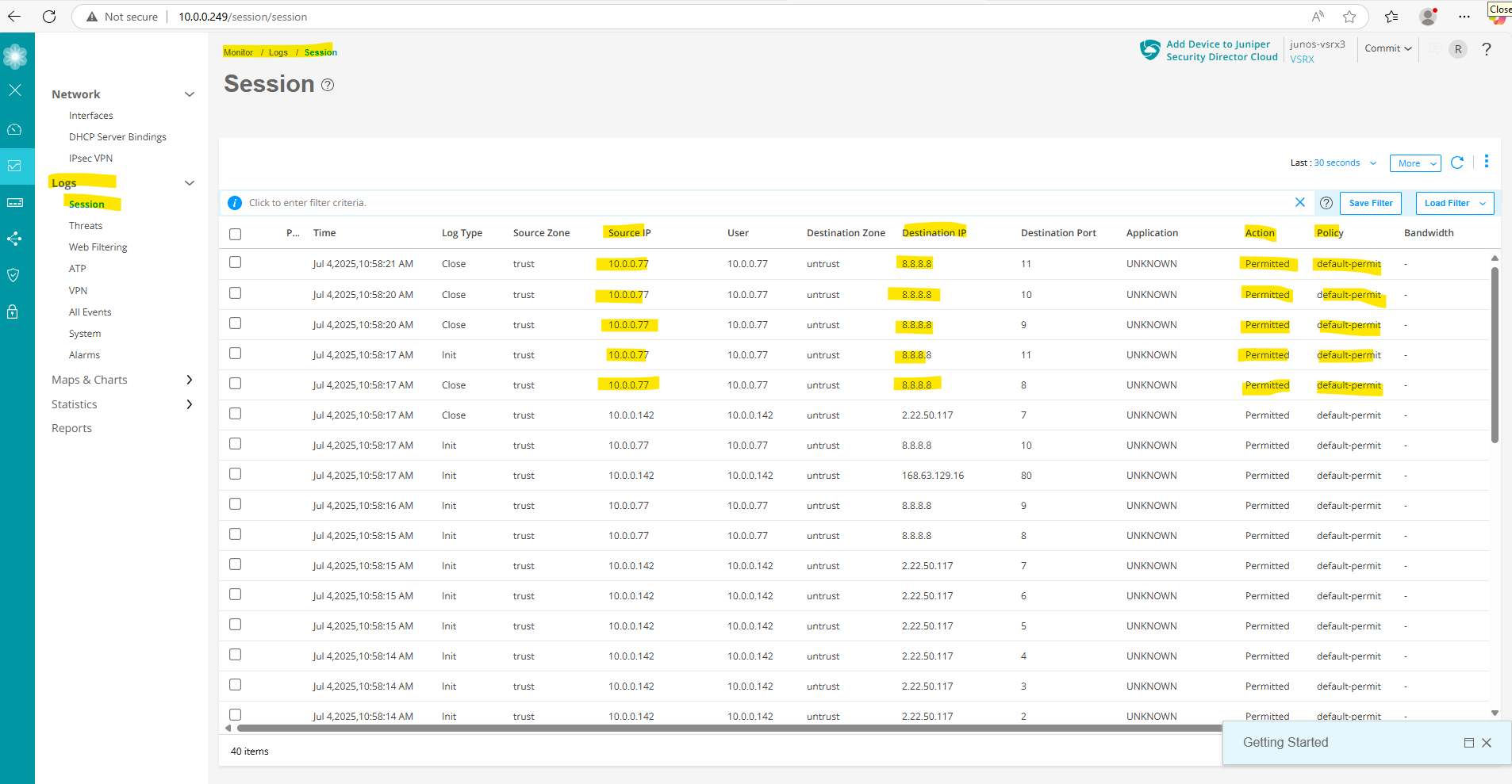
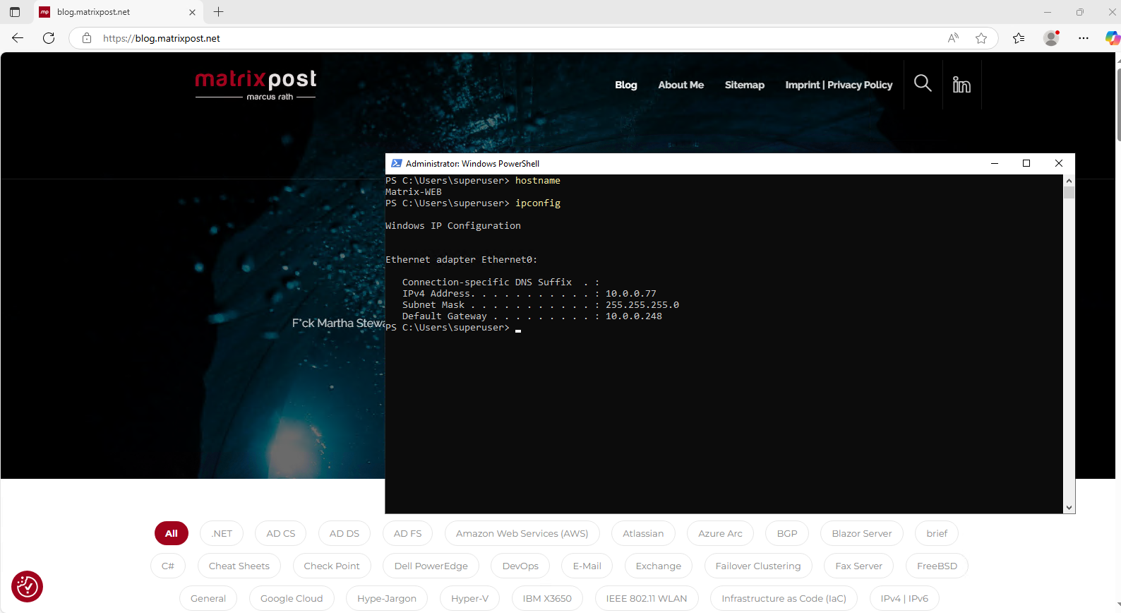
To demonstrate the logging of traffic sessions and here for our above configured policy, I will trigger outbound traffic (ICMP Echo Request messages) from my internal host Matrix-Web (IP 10.0.0.77).

Below we can see under Monitor -> Logs -> Session our outbound ICMP Echo request messages
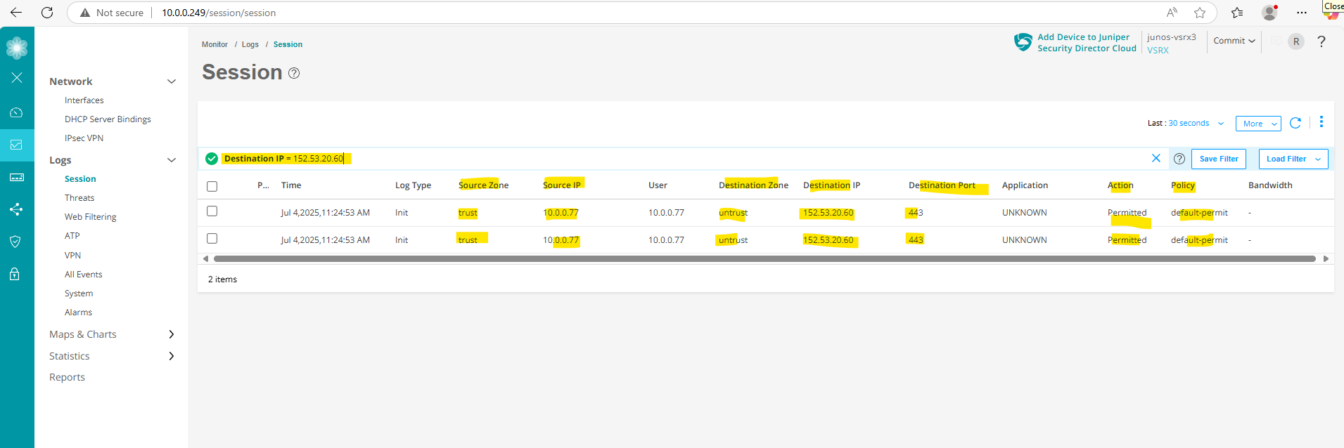
Further I will open my blog running with the public IP address 152.53.20.60 on this internal host to also trigger outbound HTTPS traffic.
We can also filter the logs to search for specific logs we want to check. Below we can see the outbound HTTPS traffic to my blog.
One more example by logging traffic sessions but this time for our previously further above configured destination NAT rule to publish our internal web server (IIS) to the internet.
Here you can see the configured destination NAT rule.
And here the corresponding security policy on which logging is enabled.
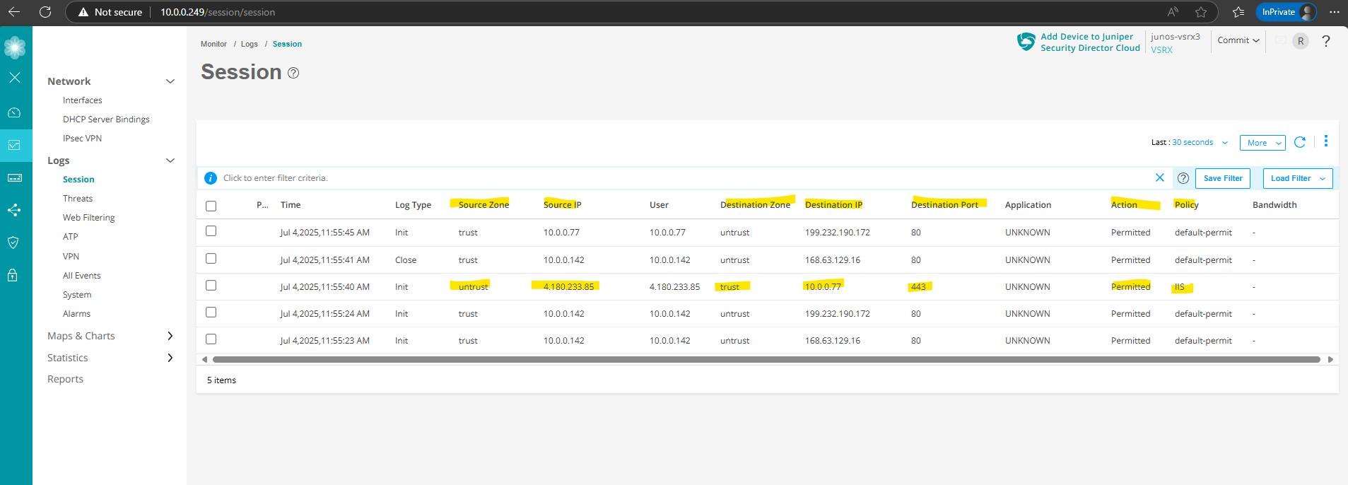
I will now first trigger HTTPs traffic to the internal web server (IIS) from my external Azure VM and its public IP address 4.180.233.85.

Under Monitor -> Logs -> Session we will see the corresponding captured traffic in the logs.
Capture Traffic on Fritz!Box
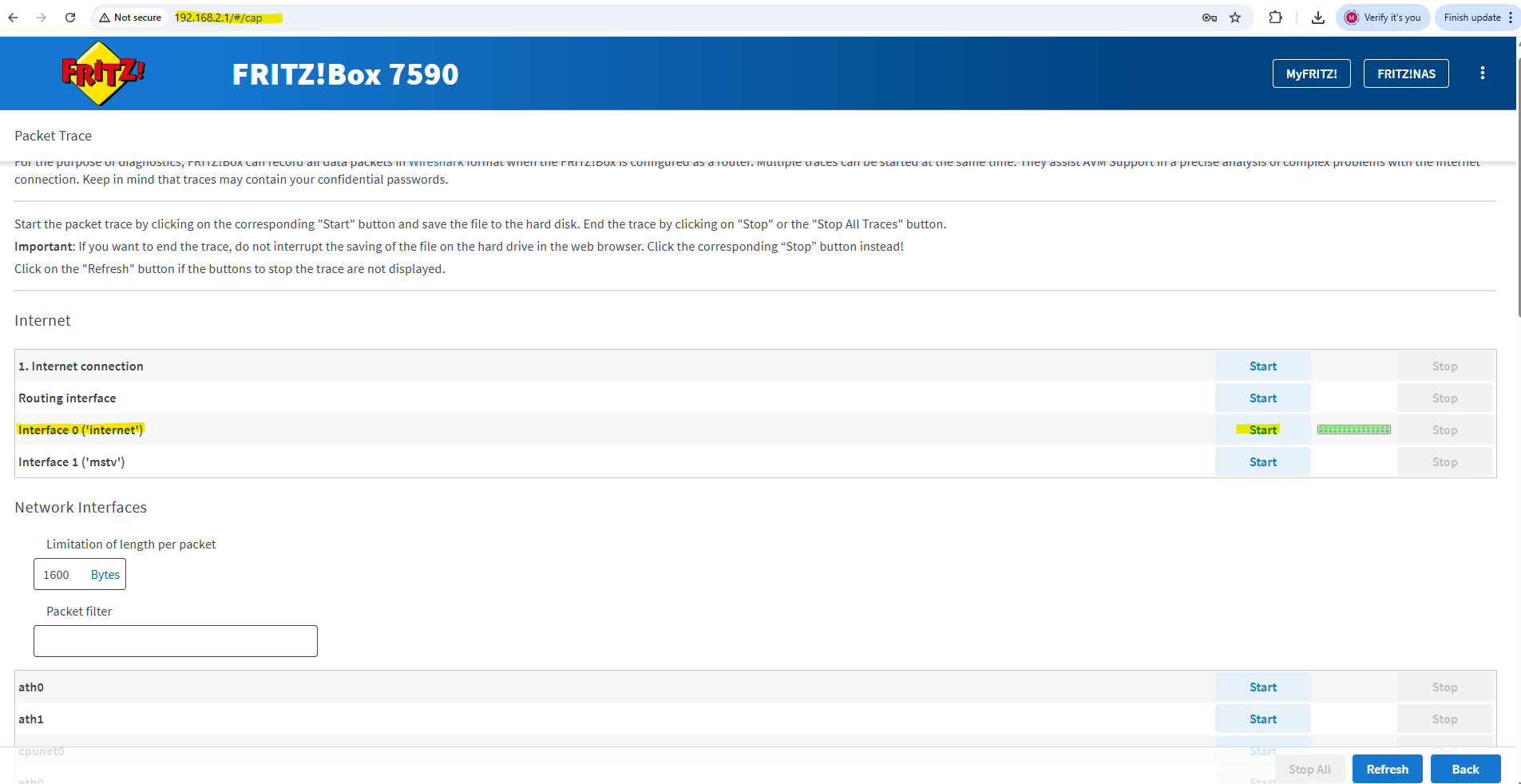
To capture traffic on a Fritz!Box, you can use its built-in packet capture feature (not widely advertised, but very useful).
First sign-in to the web interface of your Fritz!Box and then enter directly the following link. This brings you to a hidden diagnostic page on your Fritz!Box.
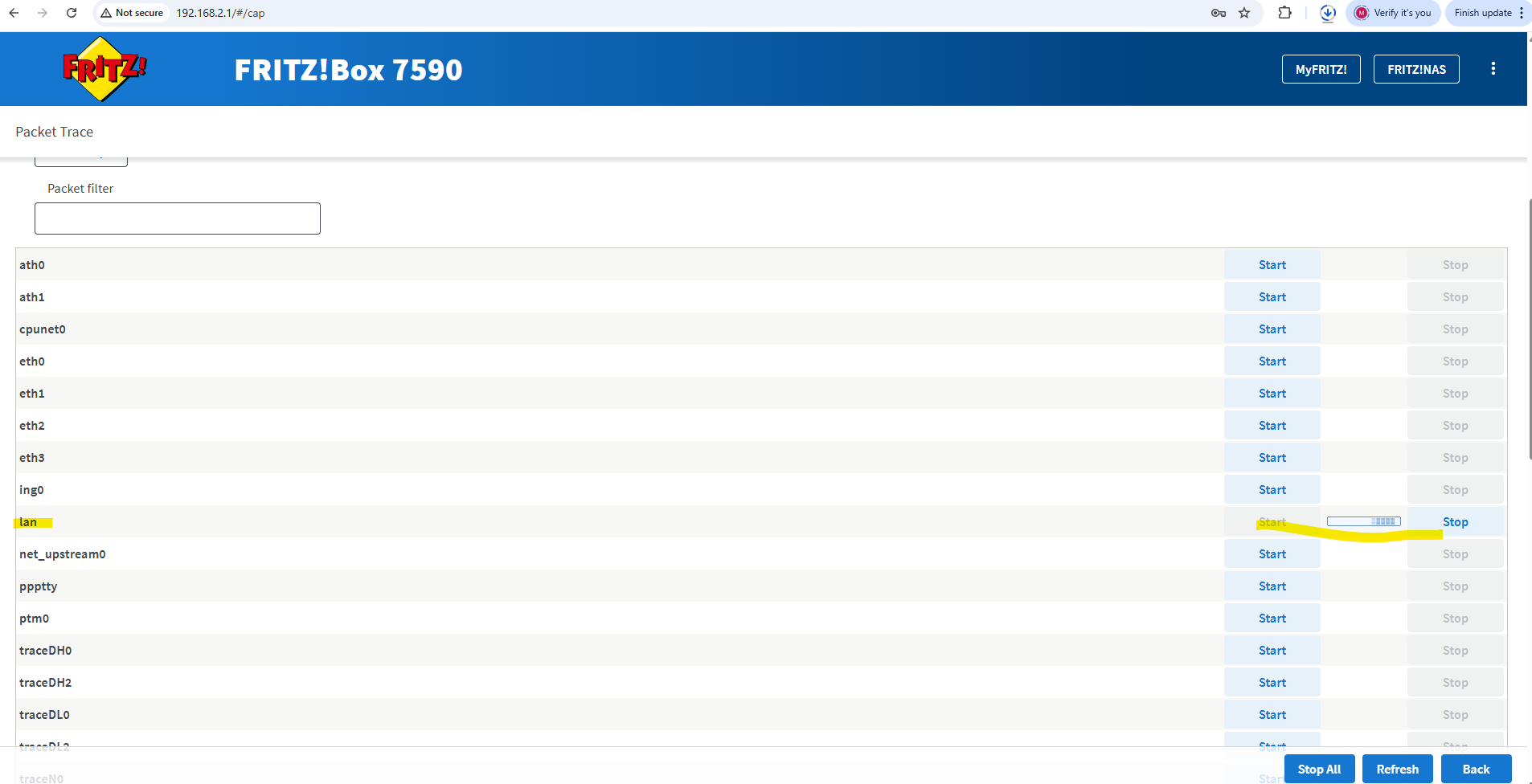
Choose the interface you want to capture traffic from and click on Start.
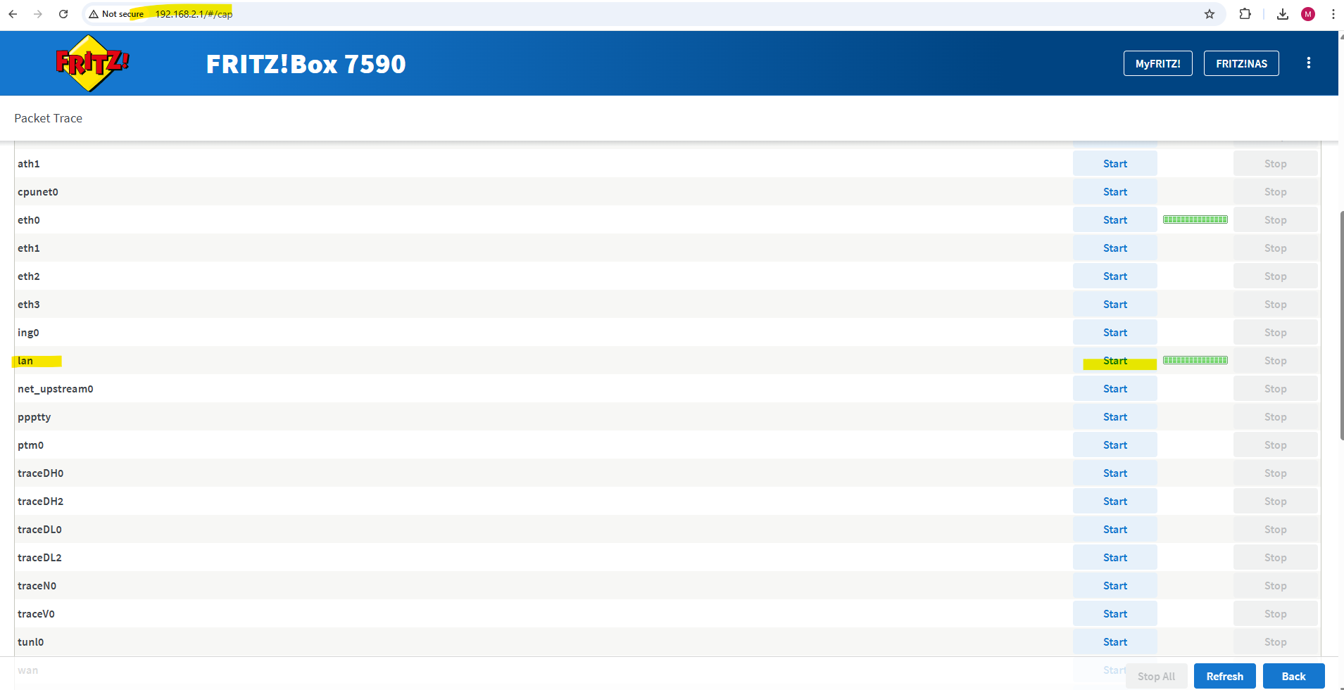
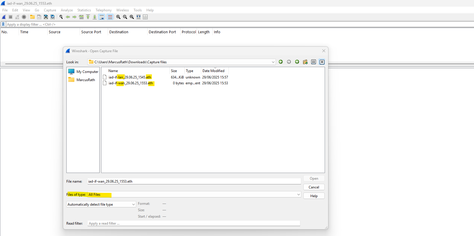
Click on stop to finish capturing, during the capturing all traffic is directly downloaded into an *.eth file.
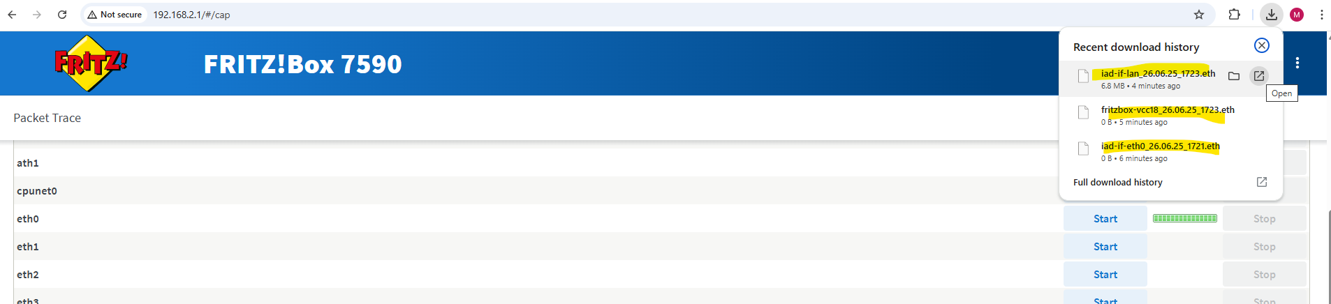
This *.eth file we can open and analyze by using WireShark.
Links
SRX Series Firewalls
https://www.juniper.net/us/en/products/security/srx-series.htmlJuniper Licensing User Guide
https://www.juniper.net/documentation/us/en/software/license/juniper-licensing-user-guide/index.htmlvSRX Deployment Guide for VMware
https://www.juniper.net/documentation/us/en/software/vsrx/vsrx-vmware/vsrx-vmware.pdfvSRX Virtual Firewall User Guide for Private and Public Cloud Platforms
https://www.juniper.net/documentation/us/en/software/vsrx/vsrx-consolidated-user-guide/vsrx-consolidated-user-guide.pdfAdd vSRX Virtual Firewall Interfaces
https://www.juniper.net/documentation/us/en/software/vsrx/vsrx-consolidated-deployment-guide/vsrx-vmware/topics/task/security-vsrx-vmware-adding-interfaces-update.htmlUser Access and Authentication Administration Guide for Junos OS
https://www.juniper.net/documentation/us/en/software/junos/user-access/topics/topic-map/user-access-root-password.htmlJuniper vSRX Setup & Initial Configuration Guide
https://journey2theccie.wordpress.com/2021/02/04/juniper-vsrx-setup-initial-configuration-guide/Security Zones
https://www.juniper.net/documentation/us/en/software/junos/security-policies/topics/topic-map/security-zone-configuration.htmlsystem-services (Security Zones Host Inbound Traffic)
https://www.juniper.net/documentation/us/en/software/junos/cli-reference/topics/ref/statement/security-edit-system-service-zone-host-inbound-traffic.htmlExample: Configuring NAT for vSRX Virtual Firewall
https://www.juniper.net/documentation/us/en/software/vsrx/vsrx-consolidated-deployment-guide/vsrx-aws/topics/example/security-vsrx-example-aws-nat.htmlMonitor Log Messages
https://www.juniper.net/documentation/us/en/software/junos/network-mgmt/topics/topic-map/displaying-and-interpreting-system-log-message-descriptions.html