Windows Server Software Defined Networking (SDN) and Hyper-V Network Virtualization (HNV) – Part 5: Extending Overlapping Tenant Networks with VRFs
In the previous parts, we demonstrated how Hyper-V Network Virtualization (HNV) allows multiple tenants to use overlapping IP address spaces while remaining completely isolated inside the Microsoft SDN fabric.
However, once these networks are handed off to a conventional external router with a single routing table, such as pfSense, that tenant context is lost and identical prefixes can no longer be routed independently.
In this part, we replace the external pfSense router with an Ubuntu-based router using Linux VRFs (Virtual Routing and Forwarding).
Ubuntu is used here as a flexible and transparent platform for demonstrating the underlying VRF concepts; in production environments, this role would typically be provided by enterprise routing or firewall platforms with native VRF support, such as Cisco IOS/IOS XE/NX-OS, Juniper Junos, Arista EOS, Fortinet FortiGate, Palo Alto Networks PAN-OS, or Nokia SR OS.
Separate routing tables extend the tenant isolation beyond the HNV fabric while allowing both tenants to share the same WAN connection, providing a practical example of the routing concepts also used in large multitenant cloud environments.
- Extending Overlapping Tenant Networks with Virtual Routing and Forwarding (VRF)
- Verifying the Initial Connectivity State
- Connecting Tenant-CustomerB to the SDN Gateway
- Creating the L3 Transit Subnet for Tenant-CustomerB
- Configuring the Ubuntu Router Transit Interface for VLAN 41
- Registering (Onboarding) the Ubuntu Transit Interface with Network Controller
- Applying the Microsoft SDN Port Profile
- Configuring WAN Connectivity on the Ubuntu Router
- Configuring the CustomerB Transit Interface on the Ubuntu Router
- Creating the CustomerB Virtual Gateway and L3 Connection
- Establishing and Testing Basic WAN Routing Before Configuring VRFs
- Configuring VRFs for the Overlapping Tenant Networks
- Migrating Tenant-CustomerA from pfSense to the Ubuntu VRF Router
- Making the VRF and Tenant Routing Configuration Persistent
- Verifying Simultaneous Tenant Internet Access with Wireshark
- Links
Extending Overlapping Tenant Networks with Virtual Routing and Forwarding (VRF)
In the previous part, we deployed Tenant-CustomerB using the same 192.168.100.0/24 address space as Tenant-CustomerA and demonstrated how Hyper-V Network Virtualization (HNV) keeps both tenant networks isolated inside the Microsoft SDN fabric.
The next challenge is extending these overlapping networks beyond the SDN fabric. A conventional router such as our existing pfSense appliance uses a single routing domain and therefore cannot maintain independent routes for two identical 192.168.100.0/24 prefixes. Deploying a separate pfSense appliance for each tenant would provide isolated routing instances, but would not scale well in a multitenant SDN environment.
In this part, we will instead use an Ubuntu-based router with Virtual Routing and Forwarding (VRF). Separate VRFs provide independent routing tables for Tenant-CustomerA and Tenant-CustomerB, allowing their overlapping address spaces to remain isolated even after leaving the HNV fabric.
We will connect both tenants through the existing Microsoft SDN Gateway using dedicated Layer-3 transit networks, onboard the corresponding Ubuntu router interfaces with Network Controller, assign each tenant connection to its own VRF, and finally provide both routing domains with access to a shared WAN connection.
This extends the tenant separation beyond HNV and demonstrates the same fundamental routing concept used by enterprise and service-provider networks to support multiple independent routing domains on shared infrastructure.
Verifying the Initial Connectivity State
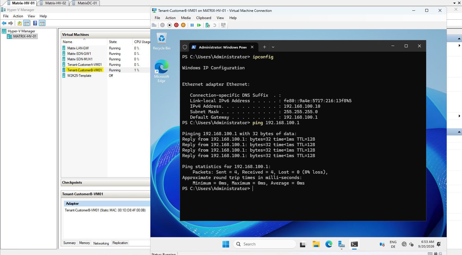
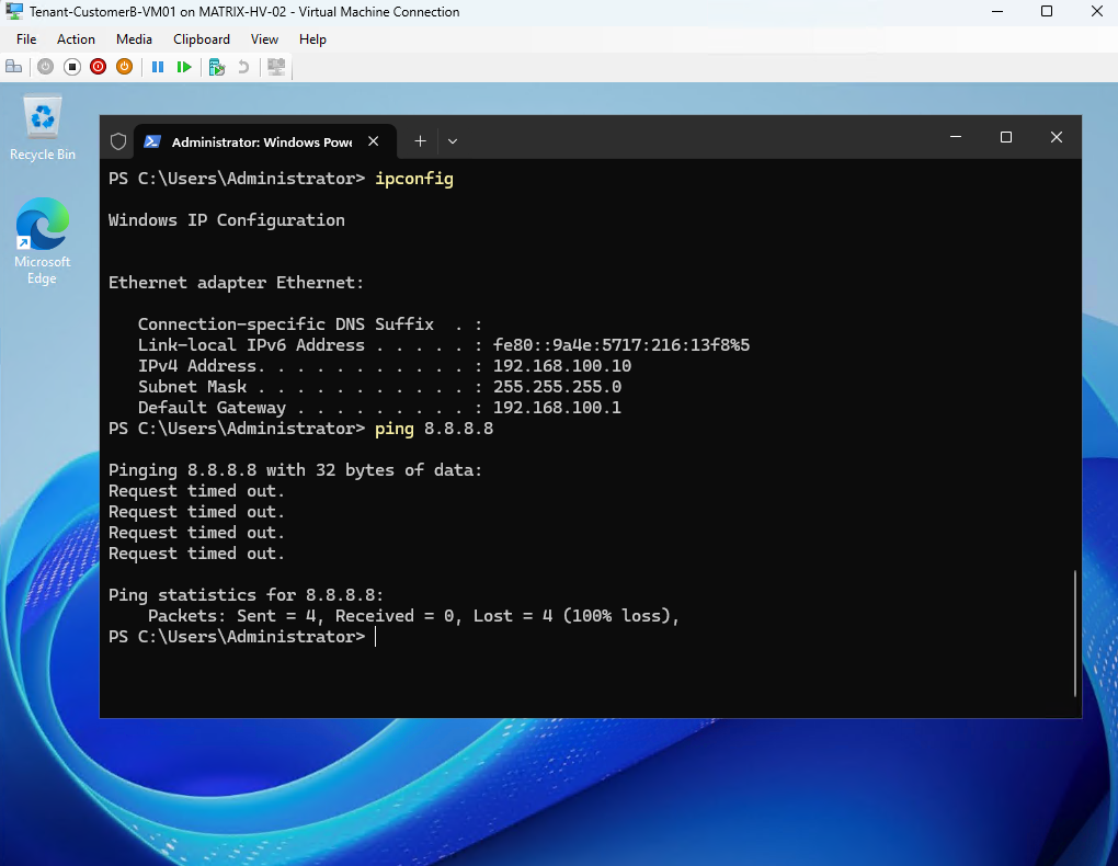
Before configuring external routing for Tenant-CustomerB, we first verify its current connectivity. The ipconfig output confirms that Tenant-CustomerB-VM01 uses 192.168.100.10/24 with the HNV-provided default gateway 192.168.100.1.
A successful ping to 192.168.100.1 confirms basic connectivity within the Tenant-CustomerB HNV virtual network.
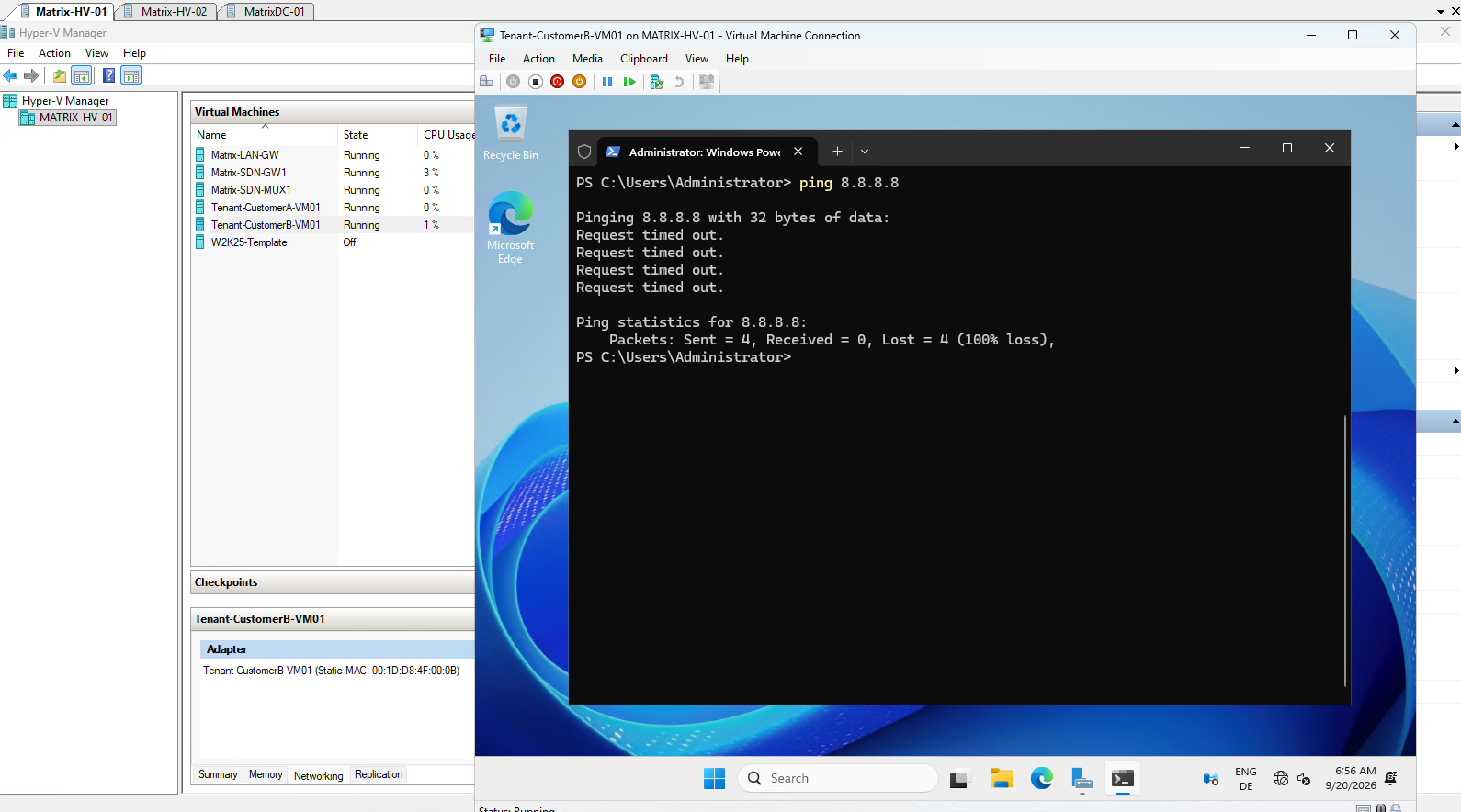
As expected, a ping to 8.8.8.8 currently fails because Tenant-CustomerB has not yet been connected to an SDN Gateway Connection providing external routing.
In the following sections, we will create the required Layer-3 transit connection for Tenant-CustomerB and connect it to our new Ubuntu-based VRF router. This will allow us to preserve the separate routing domains of Tenant-CustomerA and Tenant-CustomerB even though both tenants use the overlapping 192.168.100.0/24 address space.
Connecting Tenant-CustomerB to the SDN Gateway
To provide Tenant-CustomerB with external connectivity, we need to create a second L3 Gateway Connection. Although the existing physical SDN Gateway and Gateway Pool are shared, the Network Controller does not allow two L3 Network Connections to reference logical subnets using the same VLAN ID; therefore, the existing VLAN 40 transit subnet used by Tenant-CustomerA cannot be reused for Tenant-CustomerB.
We will therefore configure a dedicated L3 transit path for the second tenant:
Tenant-CustomerA
        │
   SDN Gateway
        │
        │ VLAN 40 / 10.0.40.0/24
        ▼
Ubuntu VRF Router
   VRF CustomerA


Tenant-CustomerB
        │
   SDN Gateway
        │
        │ VLAN 41 / 10.0.41.0/24
        ▼
Ubuntu VRF Router
   VRF CustomerB
The existing VLAN 40 / 10.0.40.0/24 transit network remains associated with Tenant-CustomerA, while VLAN 41 / 10.0.41.0/24 provides a separate L3 transit path for Tenant-CustomerB. Both transit networks will terminate on the same Ubuntu router, but each will be assigned to a separate VRF and routing table.
At this point, however, the existing Tenant-CustomerA L3 transit connection still terminates on the pfSense router configured in Part 3. Later in this article, we will migrate this external connection from pfSense to the Ubuntu router as well, so that both Tenant-CustomerA and Tenant-CustomerB can use the shared external router while retaining their independent routing domains.
This preserves the tenant-specific routing context after traffic leaves the Microsoft SDN fabric and allows both tenants to use the overlapping 192.168.100.0/24 network without creating ambiguous routes on the external router.
Creating the L3 Transit Subnet for Tenant-CustomerB
Here we create VLAN 41 / 10.0.41.0/24 in the Network Controller, add VLAN 41 to the physical switch trunks, and configure the corresponding Ubuntu router transit interface. Only after that do we create Tenant-CustomerB-VirtualGW and Tenant-CustomerB-L3.
Next, create the dedicated logical subnet for CustomerB under the existing SDN-L3-Transit logical network. Microsoft explicitly requires a unique VLAN ID for each tenant network using L3 forwarding, which matches the Network Controller error we just encountered.
$subnetProps = New-Object Microsoft.Windows.NetworkController.LogicalSubnetProperties
$subnetProps.AddressPrefix = "10.0.41.0/24"
$subnetProps.VlanID = 41
$subnetProps.DefaultGateways = @("10.0.41.1")

New-NetworkControllerLogicalSubnet -ConnectionUri $uri -LogicalNetworkId "SDN-L3-Transit" -ResourceId "SDN-L3-Transit-CustomerB-Subnet" -Properties $subnetProps -Force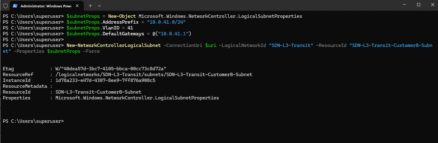
After creating the logical transit subnet, verify that Network Controller has registered VLAN 41 / 10.0.41.0/24 correctly before touching Ubuntu router.
Microsoft’s L3-forwarding configuration uses a non-virtualized logical subnet with a VLAN ID, address prefix, and default gateway for this transit network.
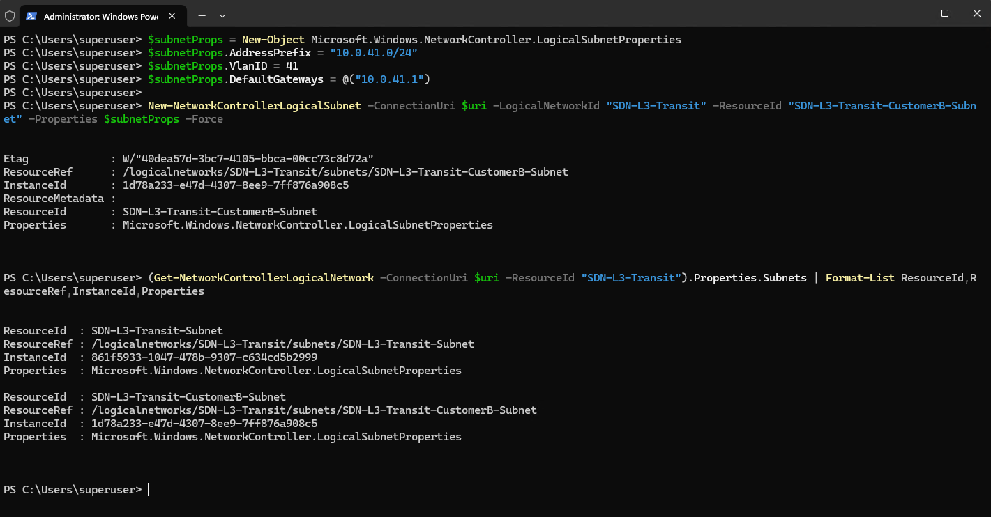
The output confirms that the existing
SDN-L3-Transitlogical network now contains two separate logical subnets. The newSDN-L3-Transit-CustomerB-Subnetprovides the dedicated VLAN 41 /10.0.41.0/24transit network required for the second tenant’s L3 Gateway Connection.
(Get-NetworkControllerLogicalNetwork -ConnectionUri $uri -ResourceId "SDN-L3-Transit").Properties.Subnets | Format-List ResourceId,ResourceRef,InstanceId,Properties
Configuring the Ubuntu Router Transit Interface for VLAN 41
Next, we connect our Ubuntu VRF router to the dedicated CustomerB transit network. For this purpose, we add a new network adapter to the Ubuntu router VM on the SDN-managed vSwitch-VM.
Add-VMNetworkAdapter -VMName "Ubuntu-Router" -SwitchName "vSwitch-VM" -Name "Transit-CustomerB"

Then place this adapter on VLAN 41:
Set-VMNetworkAdapterIsolation -VMName "Ubuntu-Router" -VMNetworkAdapterName "Transit-CustomerB" -IsolationMode Vlan -DefaultIsolationID 41 -AllowUntaggedTraffic $true

The new Transit-CustomerB network adapter is now connected to vSwitch-VM and assigned to VLAN 41 at the Hyper-V layer.
This provides a separate physical transit path for Tenant-CustomerB while leaving the existing VLAN 40 transit connection for Tenant-CustomerA unchanged.
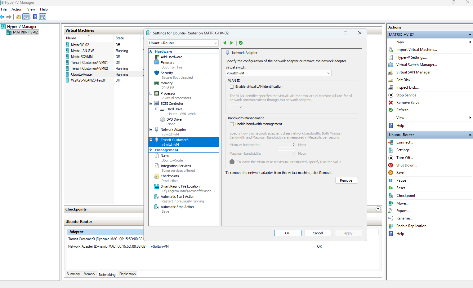
Hyper-V therefore handles the VLAN 41 tagging on behalf of the Ubuntu VM. From the guest operating system’s perspective, the corresponding network interface receives untagged Ethernet frames and does not require a separate Linux VLAN subinterface.
At this stage, the adapter is connected to the correct physical transit network, but because vSwitch-VM is managed by the Microsoft SDN stack, it must also be registered with Network Controller and associated with a Microsoft SDN Port Profile before it can participate correctly in the SDN-managed network.
Registering (Onboarding) the Ubuntu Transit Interface with Network Controller
Because vSwitch-VM is managed by the SDN forwarding extension, the new pfSense transit adapter must also be registered with Network Controller and associated with a Microsoft SDN port profile.
This allows VFP to recognize and forward traffic for the new VLAN 41 transit interface rather than treating it as an unmanaged switch port.
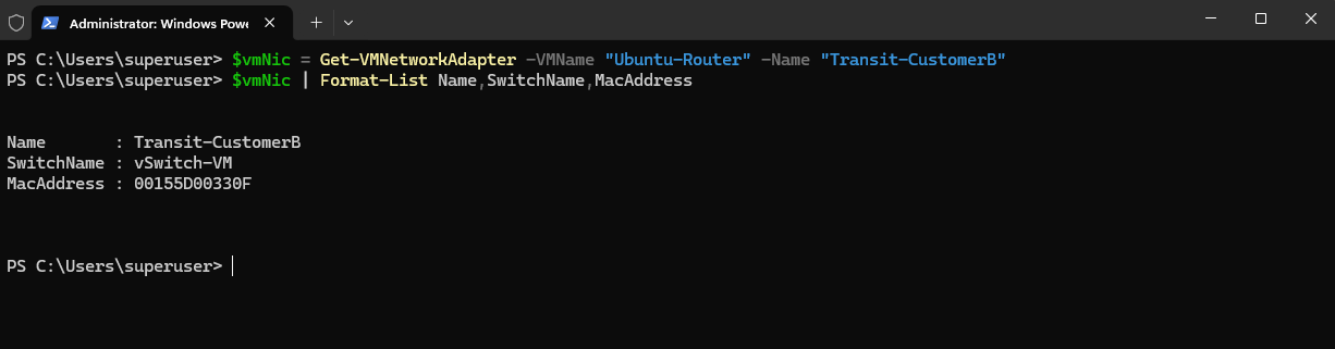
First, we retrieve the new adapter and its MAC address:
The output confirms that the new
Transit-CustomerBadapter is connected tovSwitch-VMand uses MAC address00155D00330E. We will use this MAC address when registering the interface with Network Controller.
$vmNic = Get-VMNetworkAdapter -VMName "Ubuntu-Router" -Name "Transit-CustomerB"
$vmNic | Format-List Name,SwitchName,MacAddress
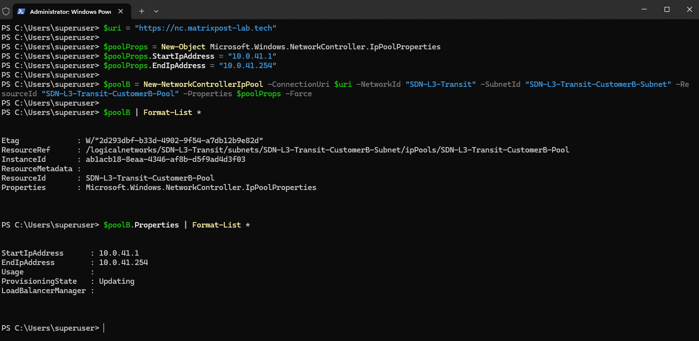
Before registering the new Ubuntu transit interface, we also need an IP pool on the VLAN 41 logical subnet. The existing CustomerA transit subnet uses an IP pool covering 10.0.40.1–10.0.40.254, so we create the equivalent 10.0.41.1–10.0.41.254 pool for CustomerB.
The new
SDN-L3-Transit-CustomerB-Poolis now associated with the CustomerB transit subnet and provides addresses from10.0.41.1through10.0.41.254.Network Controller was still reporting the resource as Updating immediately after creation, so we wait for it to reach Succeeded before continuing with the Ubuntu NetworkInterface registration.
$uri = "https://nc.matrixpost-lab.tech"

$poolProps = New-Object Microsoft.Windows.NetworkController.IpPoolProperties
$poolProps.StartIpAddress = "10.0.41.1"
$poolProps.EndIpAddress = "10.0.41.254"

$poolB = New-NetworkControllerIpPool -ConnectionUri $uri -NetworkId "SDN-L3-Transit" -SubnetId "SDN-L3-Transit-CustomerB-Subnet" -ResourceId "SDN-L3-Transit-CustomerB-Pool" -Properties $poolProps -Force

$poolB | Format-List *
$poolB.Properties | Format-List *
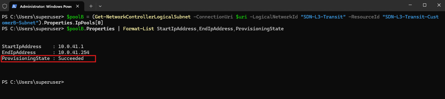
Verify:
After provisioning completes, Network Controller reports the new CustomerB transit IP pool as
Succeeded, confirming that the10.0.41.1–10.0.41.254range is ready for use.
$poolB = (Get-NetworkControllerLogicalSubnet -ConnectionUri $uri -LogicalNetworkId "SDN-L3-Transit" -ResourceId "SDN-L3-Transit-CustomerB-Subnet").Properties.IpPools[0]
$poolB.Properties | Format-List StartIpAddress,EndIpAddress,ProvisioningState
Next, we create the Network Controller NetworkInterface for the new Ubuntu transit adapter. We bind its MAC address to the new SDN-L3-Transit-CustomerB-Subnet so Network Controller knows that this interface belongs to the VLAN 41 transit network.
$uri = "https://nc.matrixpost-lab.tech"

$logicalSubnetB = Get-NetworkControllerLogicalSubnet -ConnectionUri $uri -LogicalNetworkId "SDN-L3-Transit" -ResourceId "SDN-L3-Transit-CustomerB-Subnet"

$nicProps = New-Object Microsoft.Windows.NetworkController.NetworkInterfaceProperties
$nicProps.PrivateMacAddress = "00155D00330F"
$nicProps.PrivateMacAllocationMethod = "Dynamic"

$ipConfig = New-Object Microsoft.Windows.NetworkController.NetworkInterfaceIpConfiguration
$ipConfig.ResourceId = "ipconfig1"
$ipConfig.Properties = New-Object Microsoft.Windows.NetworkController.NetworkInterfaceIpConfigurationProperties
$ipConfig.Properties.PrivateIPAllocationMethod = "Dynamic"

$ipConfig.Properties.Subnet = New-Object Microsoft.Windows.NetworkController.Subnet
$ipConfig.Properties.Subnet.ResourceRef = $logicalSubnetB.ResourceRef

$nicProps.IPConfigurations = @($ipConfig)

$nicB = New-NetworkControllerNetworkInterface -ConnectionUri $uri -ResourceId "Ubuntu-Router-Transit-CustomerB-NIC" -Properties $nicProps -Force
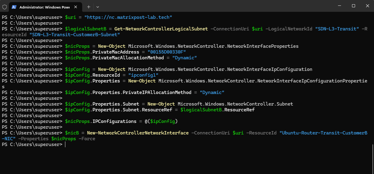
The Network Interface Ubuntu-Router-Transit-CustomerB-NIC is now successfully created and associated with the Ubuntu CustomerB transit adapter using MAC address 00155D00330F.
Network Controller keeps the IP configuration in Dynamic allocation mode and assigns an address from the newly created CustomerB transit IP pool.
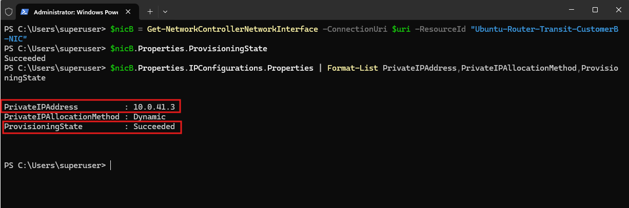
After provisioning completes, Network Controller reports the new Ubuntu router transit Network Interface as Succeeded and dynamically assigns 10.0.41.3 from the CustomerB transit IP pool.
The interface is now ready to be associated with the corresponding Hyper-V switch port through the Microsoft SDN port profile.
$uri = "https://nc.matrixpost-lab.tech"

$nicB = Get-NetworkControllerNetworkInterface -ConnectionUri $uri -ResourceId "Ubuntu-Router-Transit-CustomerB-NIC"

$nicB.Properties | Format-List PrivateMacAddress,ProvisioningState
$nicB.Properties.IPConfigurations[0].Properties | Format-List PrivateIPAddress,PrivateIPAllocationMethod,ProvisioningState
Applying the Microsoft SDN Port Profile
Next, we associate the Hyper-V switch port of Transit-CustomerB with the corresponding Network Controller NetworkInterface.
As with the existing CustomerA transit adapter, the NC InstanceId becomes the ProfileId used by the Microsoft SDN forwarding extension.
The following commands must be executed on the Hyper-V host currently running Ubuntu-Router, because the Microsoft SDN port profile is applied directly to the VM’s local Hyper-V switch port. In this lab, Ubuntu-Router is currently running on Matrix-HV-02.
$uri = "https://nc.matrixpost-lab.tech"

$vmNic = Get-VMNetworkAdapter -VMName "Ubuntu-Router" -Name "Transit-CustomerB"

$nicB = Get-NetworkControllerNetworkInterface -ConnectionUri $uri -ResourceId "Ubuntu-Router-Transit-CustomerB-NIC"

$FeatureId = "9940cd46-8b06-43bb-b9d5-93d50381fd56"
$PortProfile = Get-VMSystemSwitchExtensionPortFeature -FeatureId $FeatureId

$PortProfile.SettingData.ProfileId = "{$($nicB.InstanceId)}"
$PortProfile.SettingData.ProfileData = 2
$PortProfile.SettingData.ProfileName = "Microsoft SDN Port"
$PortProfile.SettingData.VendorId = "{1FA41B39-B444-4E43-B35A-E1F7985FD548}"

Add-VMSwitchExtensionPortFeature -VMNetworkAdapter $vmNic -VMSwitchExtensionFeature $PortProfile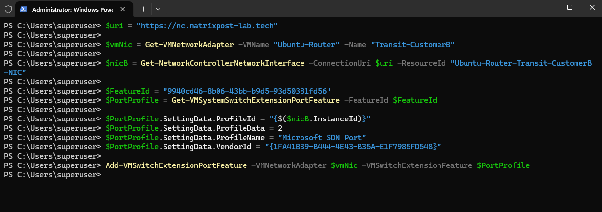
The verification confirms that the Transit-CustomerB adapter is configured for VLAN 41 and has the Microsoft SDN Port profile attached. Its ProfileId matches the InstanceId of Ubuntu-Router-Transit-CustomerB-NIC, confirming that the Hyper-V switch port is correctly associated with the corresponding Network Controller resource.
Get-VMSwitchExtensionPortFeature -VMNetworkAdapter $vmNic | Where-Object {$_.Id -eq "9940cd46-8b06-43bb-b9d5-93d50381fd56"} | Select-Object -ExpandProperty SettingData | Format-List ProfileId,ProfileData,ProfileName,VendorId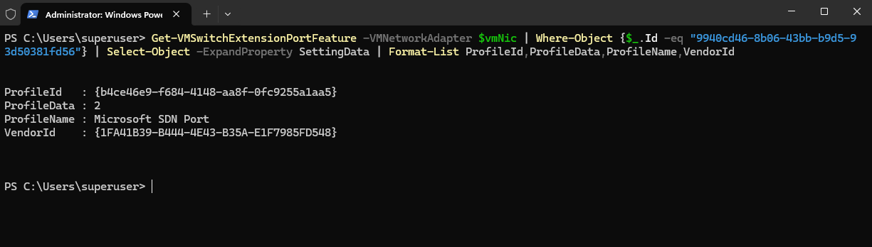
Configuring WAN Connectivity on the Ubuntu Router
Before configuring the tenant transit interfaces and VRFs, we first provide the Ubuntu router with external network connectivity. For this purpose, we add a third network adapter connected to vSwitch-VM and use VLAN 100 to connect it to the Fritz!Box network 192.168.178.0/24.
Hyper-V performs the VLAN tagging, while Ubuntu uses DHCP on eth2 to obtain its WAN configuration from the Fritz!Box. Because vSwitch-VM is SDN-managed, the WAN adapter also requires an unmanaged Microsoft SDN Port Profile (ProfileData = 2) so that normal traffic can pass through the VFP datapath.
Setting
ProfileData = 2marks the adapter as an unmanaged SDN port, allowing normal traffic to pass through the VFP datapath without the port being managed by Network Controller. The profile is then attached to the Hyper-V VM network adapter usingAdd-VMSwitchExtensionPortFeature.
$vmNic = Get-VMNetworkAdapter -VMName "Ubuntu-Router" -Name "WAN"
$FeatureId = "9940cd46-8b06-43bb-b9d5-93d50381fd56"
$PortProfile = Get-VMSystemSwitchExtensionPortFeature -FeatureId $FeatureId
$PortProfile.SettingData.ProfileId = "{00000000-0000-0000-0000-000000000000}"
$PortProfile.SettingData.ProfileData = 2
$PortProfile.SettingData.ProfileName = "Testprofile"
$PortProfile.SettingData.VendorId = "{1FA41B39-B444-4E43-B35A-E1F7985FD548}"
Add-VMSwitchExtensionPortFeature -VMNetworkAdapter $vmNic -VMSwitchExtensionFeature $PortProfile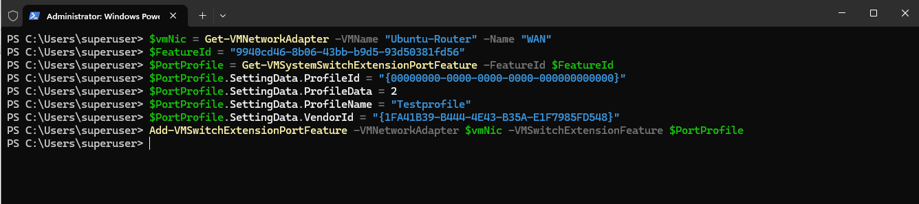
After applying the SDN port profile, we triggered a new DHCP attempt on the WAN interface with sudo networkctl reconfigure eth2.
The interface then successfully obtained
192.168.178.60/24from the Fritz!Box DHCP server.
sudo networkctl reconfigure eth2

The
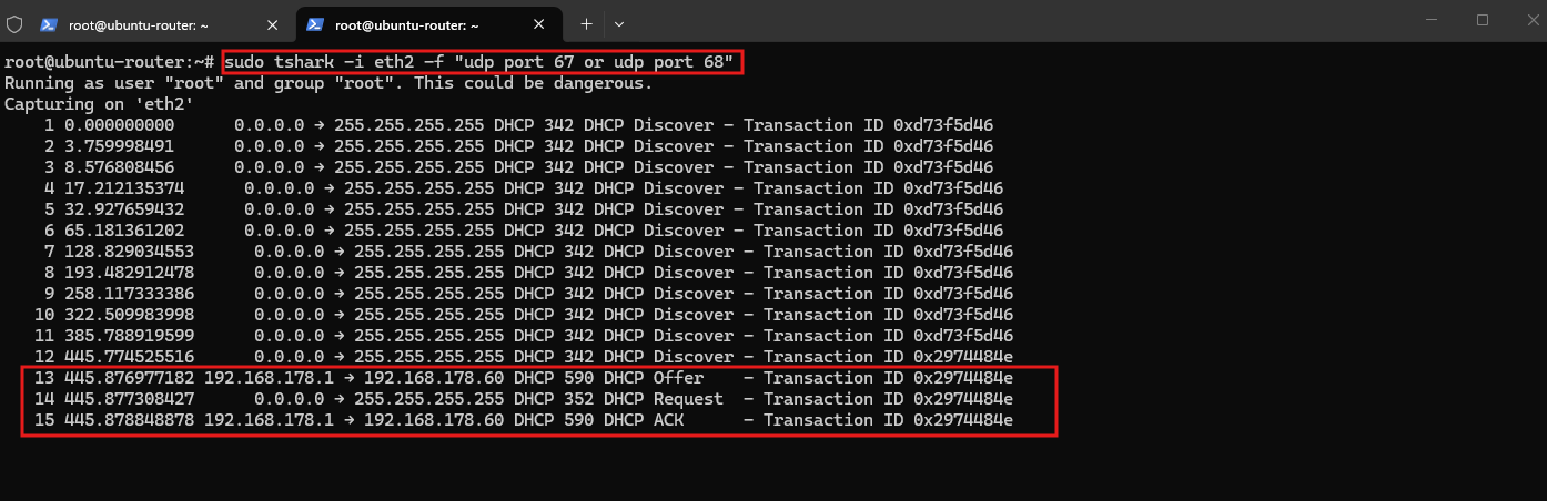
tsharkcapture confirms the complete DHCP DORA exchange: Discover → Offer → Request → ACK. The Fritz!Box at192.168.178.1offered and acknowledged192.168.178.60, confirming that VLAN 100 and the WAN Layer-2 path were working correctly.
sudo tshark -i eth2 -f "udp port 67 or udp port 68"
More about capturing traffic on Linux by using TShark you can read my following article.
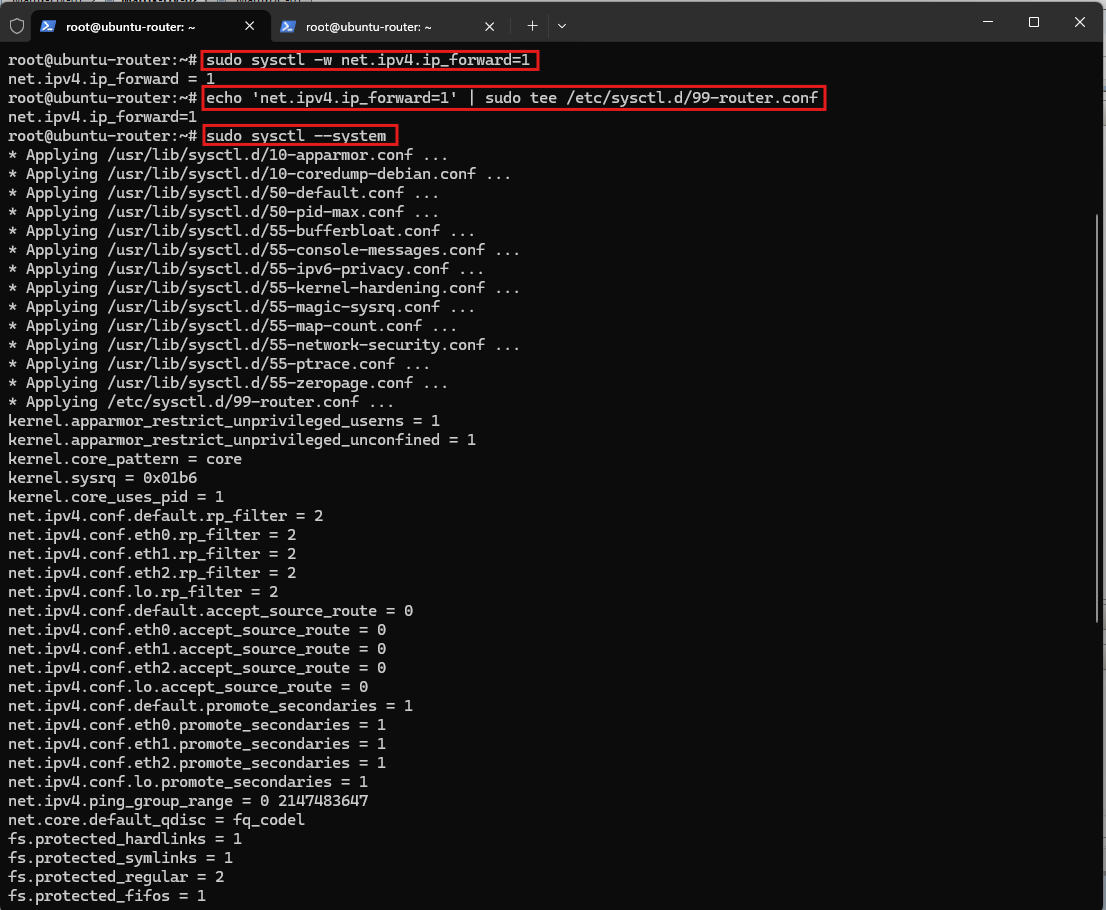
Since Ubuntu will route traffic between the tenant transit networks and the WAN, IPv4 forwarding must be enabled.
This allows the Linux kernel to forward IPv4 packets between interfaces instead of processing only traffic addressed to the router itself.
sudo sysctl -w net.ipv4.ip_forward=1

Make it persistent:
echo 'net.ipv4.ip_forward=1' | sudo tee /etc/sysctl.d/99-router.conf
sudo sysctl --system
Configuring the CustomerB Transit Interface on the Ubuntu Router
Since VLAN 41 tagging is performed by the Hyper-V virtual switch, the Ubuntu VM receives the CustomerB transit network as an untagged Ethernet interface. Therefore, we do not create a VLAN 41 subinterface inside Ubuntu.
Network Controller has dynamically allocated 10.0.41.3 to the Ubuntu router’s CustomerB transit interface. We therefore use this address for eth1 and later configure the SDN Gateway L3 connection with a different address from the same 10.0.41.0/24 transit network.
$uri = "https://nc.matrixpost-lab.tech"
$nic = Get-NetworkControllerNetworkInterface -ConnectionUri $uri -ResourceId "Ubuntu-Router-Transit-CustomerB-NIC"
$nic.Properties.IPConfigurations | Format-List ResourceId,@{N="PrivateIPAddress";E={$_.Properties.PrivateIPAddress}},@{N="AllocationMethod";E={$_.Properties.PrivateIPAllocationMethod}}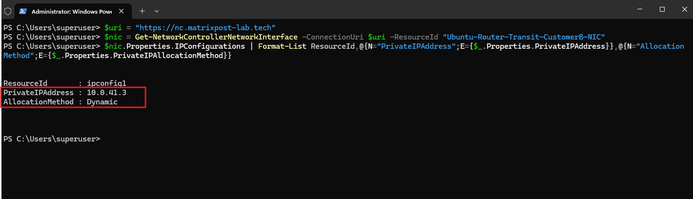
Now we configure the CustomerB transit address 10.0.41.3/24 on eth1 using Netplan. No default gateway is configured on this interface because it is dedicated exclusively to the CustomerB transit network.
nano /etc/netplan/00-installer-config.yaml
# This is the network config written by 'subiquity'
network:
  ethernets:
    eth0:
      addresses:
        - 10.0.0.2/24
      match:
        macaddress: 00:15:5d:00:33:0b
      nameservers:
        addresses:
          - 10.0.0.70
        search:
          - matrixpost-lab.tech
      set-name: eth0
    eth1:
      addresses:
        - 10.0.41.3/24
      match:
        macaddress: 00:15:5d:00:33:0f
      set-name: eth1
    eth2:
      dhcp4: true
  version: 2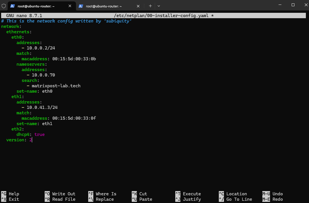
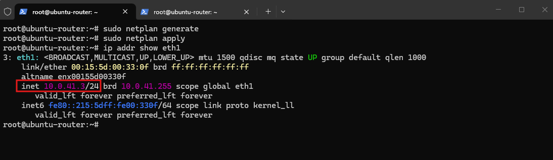
netplan generatefirst validates the YAML before actually applying anything.
sudo netplan generate
sudo netplan apply
ip addr show eth1
Creating the CustomerB Virtual Gateway and L3 Connection
Now that the Ubuntu router is reachable through the dedicated VLAN 41 transit network, we can create the tenant Virtual Gateway and its L3 connection. Microsoft defines the Local IP as the address on the SDN Gateway L3 interface and the Peer IP as the external router, in our case the Ubuntu router at 10.0.41.3.
Next, we create the Virtual Gateway for Tenant-CustomerB and associate it with the existing SDN Gateway infrastructure and the tenant’s dedicated gateway subnet. This provides the tenant-specific routing instance required before its L3 Gateway Connection can be configured.
$uri = "https://nc.matrixpost-lab.tech"

$vnetB = Get-NetworkControllerVirtualNetwork -ConnectionUri $uri -ResourceId "Tenant-CustomerB"
$gwSubnetB = $vnetB.Properties.Subnets | Where-Object ResourceId -eq "Tenant-CustomerB-Gateway-Subnet"
$gwPool = (Get-NetworkControllerGatewayPool -ConnectionUri $uri)[0]

$vgwBProps = New-Object Microsoft.Windows.NetworkController.VirtualGatewayProperties
$vgwBProps.RoutingType = "Dynamic"
$vgwBProps.GatewayPools = @($gwPool)
$vgwBProps.GatewaySubnets = @($gwSubnetB)

$vgwB = New-NetworkControllerVirtualGateway -ConnectionUri $uri -ResourceId "Tenant-CustomerB-VirtualGW" -Properties $vgwBProps -Force

$vgwB | Format-List ResourceId,InstanceId
$vgwB.Properties | Format-List RoutingType,ProvisioningState
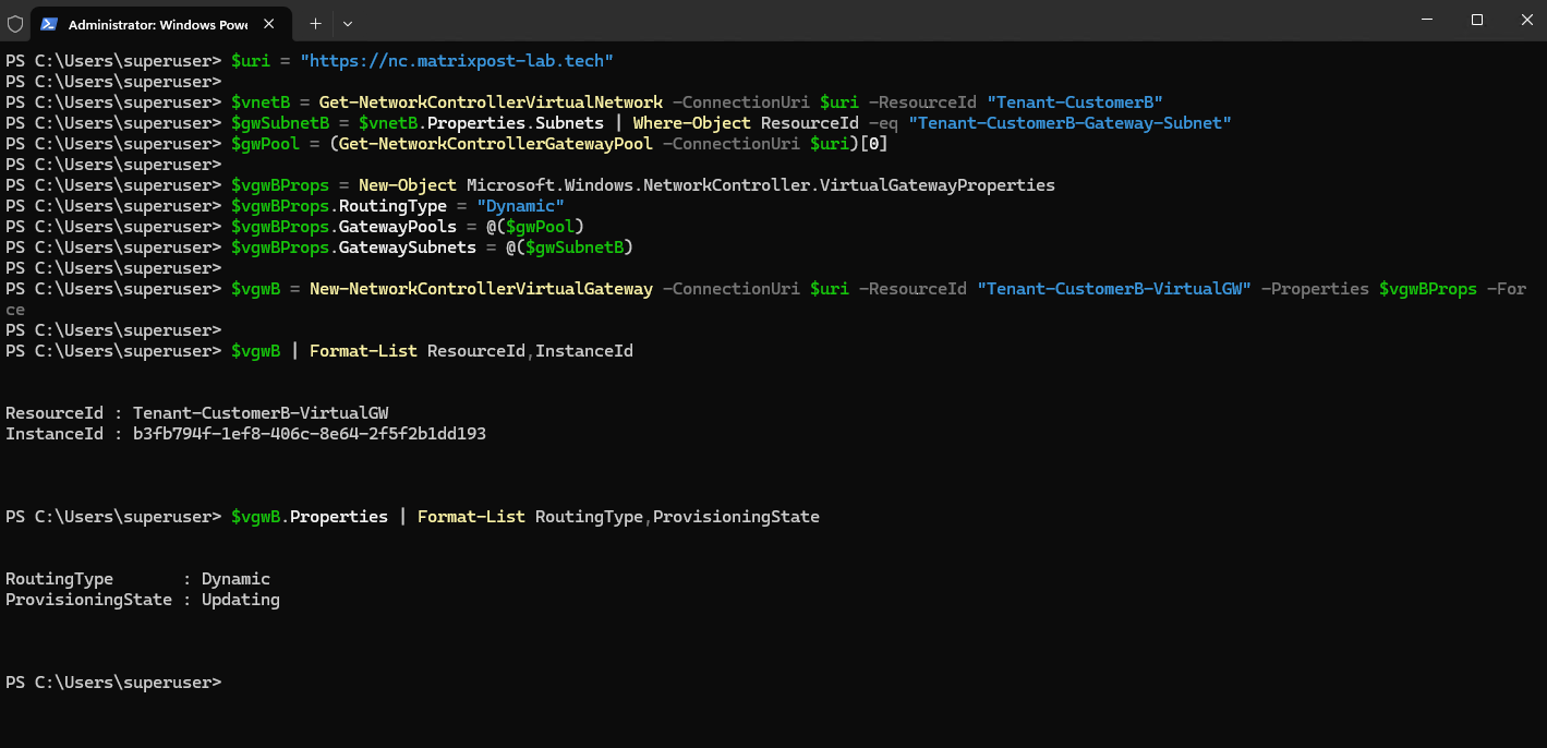
The output confirms that Tenant-CustomerB-VirtualGW has been created and is currently being provisioned by Network Controller. Before creating the L3 connection, we wait until its ProvisioningState changes to Succeeded.
Verify:
The
Succeededprovisioning state confirms thatTenant-CustomerB-VirtualGWis fully provisioned and ready for the L3 Gateway Connection.
(Get-NetworkControllerVirtualGateway -ConnectionUri $uri -ResourceId "Tenant-CustomerB-VirtualGW").Properties | Format-List RoutingType,ProvisioningState

Next, we create the L3 Gateway Connection between Tenant-CustomerB-VirtualGW and the dedicated VLAN 41 transit network. For this connection, we use 10.0.41.4/24 as the Local IP of the SDN Gateway L3 interface and the Ubuntu router address 10.0.41.3 as the Peer IP.
$uri = "https://nc.matrixpost-lab.tech"

$vgwB = Get-NetworkControllerVirtualGateway -ConnectionUri $uri -ResourceId "Tenant-CustomerB-VirtualGW"
$logicalSubnetB = Get-NetworkControllerLogicalSubnet -ConnectionUri $uri -LogicalNetworkId "SDN-L3-Transit" -ResourceId "SDN-L3-Transit-CustomerB-Subnet"

$connProps = New-Object Microsoft.Windows.NetworkController.NetworkConnectionProperties
$connProps.ConnectionType = "L3"
$connProps.OutboundKiloBitsPerSecond = 10000
$connProps.InboundKiloBitsPerSecond = 10000

$connProps.L3Configuration = New-Object Microsoft.Windows.NetworkController.L3Configuration
$connProps.L3Configuration.VlanSubnet = $logicalSubnetB

$localIP = New-Object Microsoft.Windows.NetworkController.CidrIPAddress
$localIP.IPAddress = "10.0.41.4"
$localIP.PrefixLength = 24
$connProps.IPAddresses = @($localIP)

$connProps.PeerIPAddresses = @("10.0.41.3")

$route = New-Object Microsoft.Windows.NetworkController.RouteInfo
$route.DestinationPrefix = "0.0.0.0/0"
$route.NextHop = "0.0.0.0"
$route.Metric = 10
$route.Protocol = "Static"
$connProps.Routes = @($route)

$connB = New-NetworkControllerVirtualGatewayNetworkConnection -ConnectionUri $uri -VirtualGatewayId $vgwB.ResourceId -ResourceId "Tenant-CustomerB-L3" -Properties $connProps -Force

$connB.Properties | Format-List ConnectionType,IPAddresses,PeerIPAddresses,ConnectionState,ProvisioningState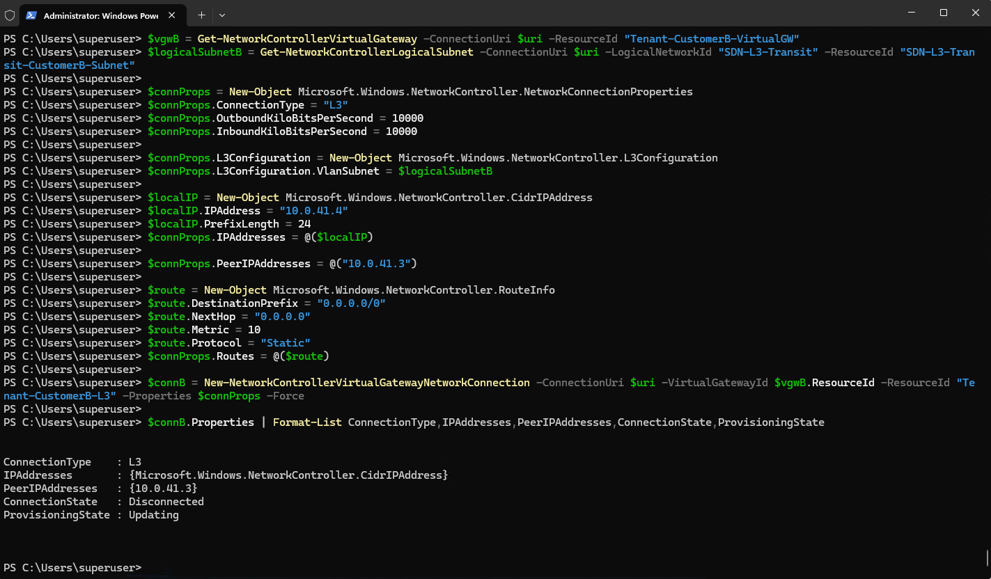
Network Controller accepts the new Tenant-CustomerB-L3 connection with the Ubuntu router 10.0.41.3 configured as its Peer IP. The connection initially reports Updating and Disconnected while the configuration is being deployed to the SDN Gateway.
Verify its state:
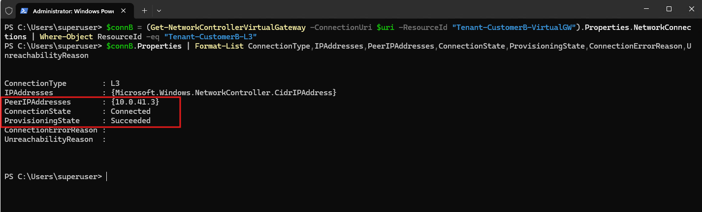
The connection now reports Connected and Succeeded, confirming that Tenant-CustomerB-L3 has been successfully provisioned and that the SDN Gateway has established the L3 connection toward the Ubuntu router peer
10.0.41.3.
$connB = (Get-NetworkControllerVirtualGateway -ConnectionUri $uri -ResourceId "Tenant-CustomerB-VirtualGW").Properties.NetworkConnections | Where-Object ResourceId -eq "Tenant-CustomerB-L3"
$connB.Properties | Format-List ConnectionType,IPAddresses,PeerIPAddresses,ConnectionState,ProvisioningState,ConnectionErrorReason,UnreachabilityReason
Windows Admin Center confirms both Tenant-CustomerA-L3 and the newly created Tenant-CustomerB-L3 connections are Connected with a Success configuration state, each associated with its respective tenant virtual network.
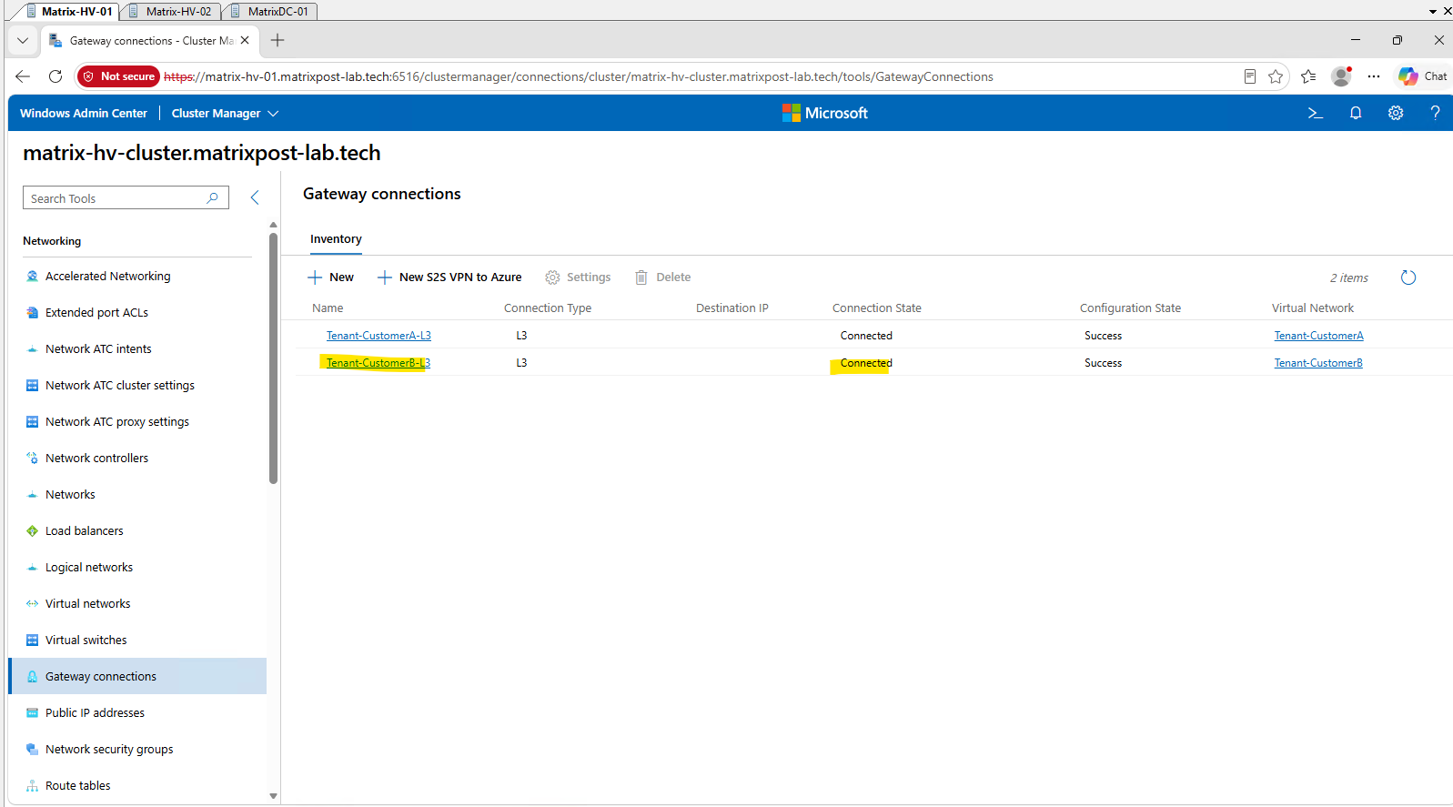
With both tenant L3 Gateway Connections now successfully established, the Microsoft SDN side of the external routing path is complete. We can therefore move to the Ubuntu router and configure separate VRFs and routing tables for the overlapping tenant networks.
Establishing and Testing Basic WAN Routing Before Configuring VRFs
Before introducing VRFs, we first establish and verify the complete routing path for Tenant-CustomerB using the main Linux routing table. This provides a working baseline and clearly separates basic routing, IP forwarding, return routing, and NAT from the additional routing isolation later provided by VRFs.
The test also illustrates how many independent components are involved in providing Internet connectivity to an HNV tenant: the tenant virtual gateway, SDN Gateway, L3 transit network, Ubuntu routing table, Linux IP forwarding, WAN route, and source NAT must all work together.
Before making any changes to the Ubuntu router, we first verify the initial connectivity state from Tenant-CustomerB-VM01. The VM is correctly configured with 192.168.100.10/24 and the HNV virtual default gateway 192.168.100.1, but Internet connectivity to 8.8.8.8 currently fails.
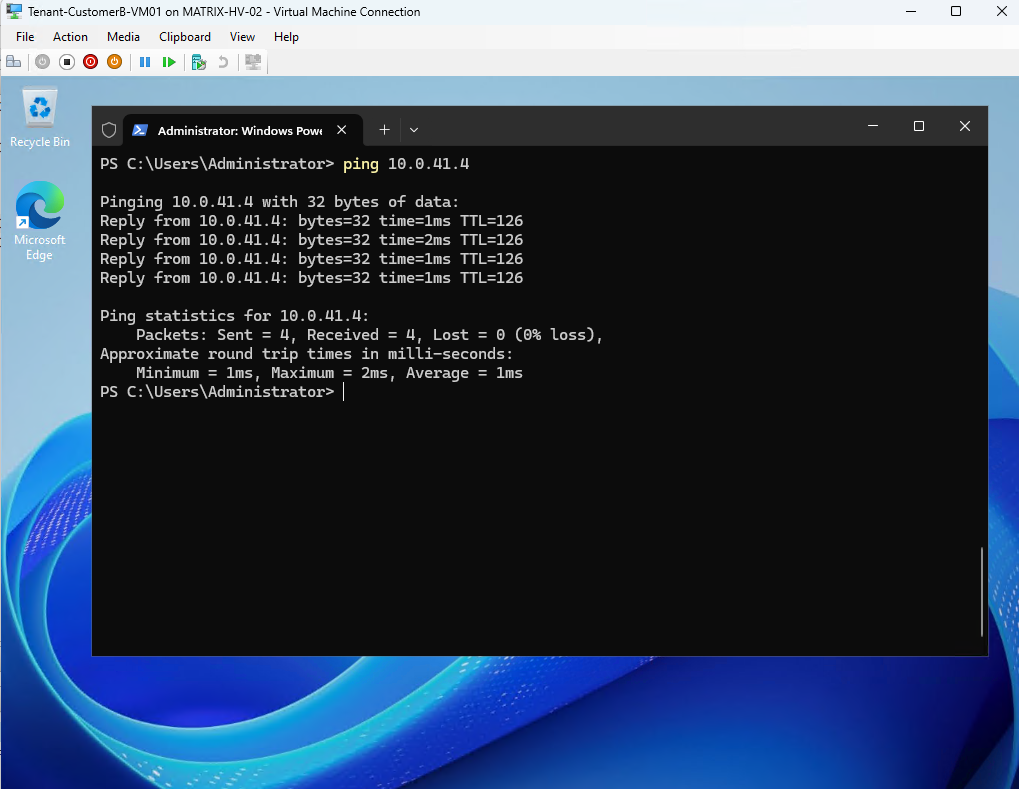
A ping to 10.0.41.4, the CustomerB L3 interface on the SDN Gateway, succeeds.
This confirms that Tenant-CustomerB traffic is successfully routed through the HNV fabric to the SDN Gateway; the remaining connectivity problem therefore lies beyond this point in the external routing path.
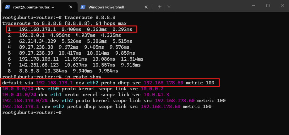
We then verify the Ubuntu router itself has working WAN connectivity. traceroute confirms that traffic to 8.8.8.8 leaves through the Fritz!Box at 192.168.178.1, while ip route show confirms the default route uses the WAN interface eth2.
However, the routing table currently contains no route back to the CustomerB network
192.168.100.0/24, which we need to add through the SDN Gateway at10.0.41.4.
traceroute 8.8.8.8
ip route show
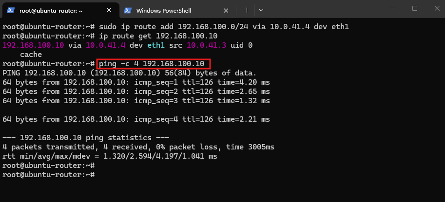
We temporary add a route for the CustomerB network 192.168.100.0/24 via the SDN Gateway L3 interface 10.0.41.4 on eth1. ip route get confirms the selected path, and the successful ping to 192.168.100.10 verifies bidirectional connectivity between the Ubuntu router and Tenant-CustomerB.
For this initial test, we leave the route temporary in the main Linux routing table. Later, when configuring VRFs, the route to
192.168.100.0/24will instead be configured in the dedicated CustomerB VRF routing table.
sudo ip route add 192.168.100.0/24 via 10.0.41.4 dev eth1
ip route get 192.168.100.10
ping -c 4 192.168.100.10
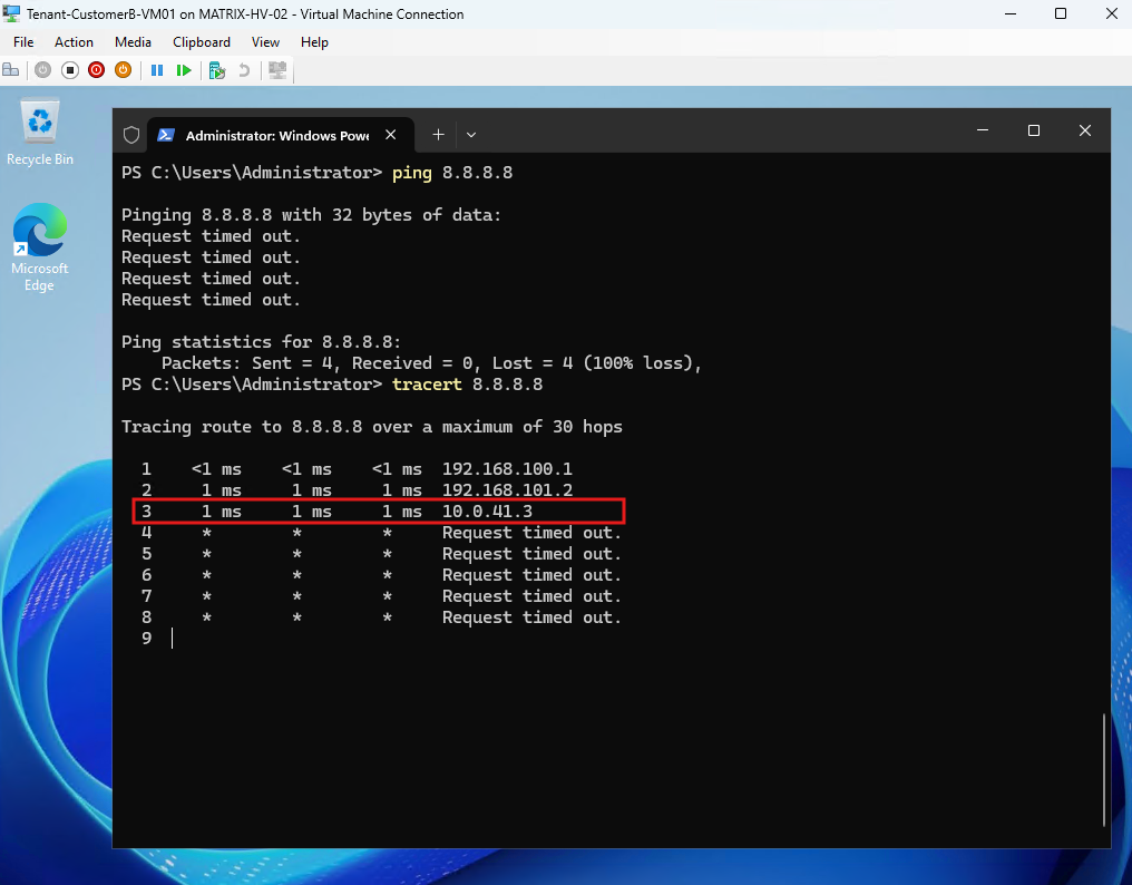
Repeating the Internet test from Tenant-CustomerB-VM01 still fails, but tracert now reveals the complete path as far as the Ubuntu router: HNV virtual gateway 192.168.100.1 → SDN Gateway 192.168.101.2 → Ubuntu router 10.0.41.3.
From this point, Ubuntu must forward the traffic toward its WAN interface and apply source NAT, because the upstream Fritz!Box has no route back to the tenant network
192.168.100.0/24.
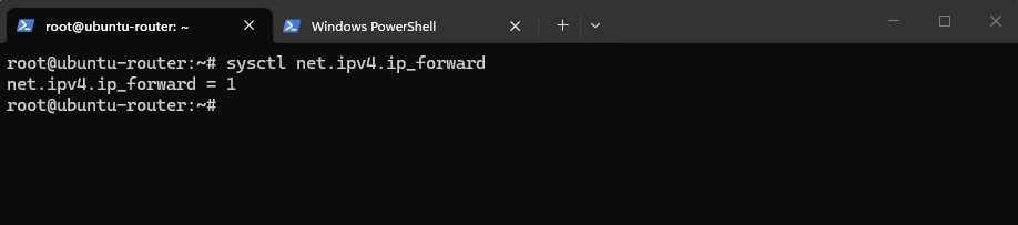
IPv4 forwarding was already enabled earlier on the Ubuntu router, as confirmed by net.ipv4.ip_forward = 1.
This is required because Ubuntu must forward packets between the tenant transit interface (
eth1) and the WAN interface (eth2) instead of processing only traffic addressed to the router itself.By default, both Linux and Windows do not act as IP routers for forwarded traffic, primarily for security reasons, forwarding must therefore be explicitly enabled so Ubuntu can route packets between the tenant transit interface (
eth1) and the WAN interface (eth2).
verify:
sysctl net.ipv4.ip_forward

enable:
sudo sysctl -w net.ipv4.ip_forward=1
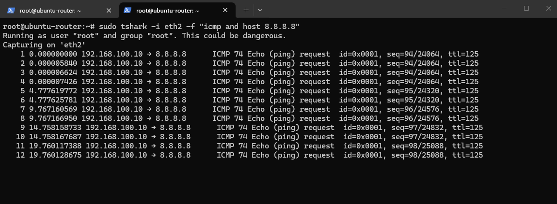
The capture on the Ubuntu WAN interface eth2 confirms that CustomerB traffic is successfully forwarded toward the Internet, but still leaves with its original source address 192.168.100.10.
Because the upstream Fritz!Box has no route back to this tenant network, we need to configure source NAT (SNAT) on the Ubuntu router.
sudo tshark -i eth2 -f "icmp and host 8.8.8.8"
To provide Internet access for the tenant network, we configure source NAT (SNAT) on the Ubuntu router using nftables.
Before configuring NAT, we verify the current nftables ruleset:
The empty output confirms that no nftables rules are currently configured, giving us a clean baseline before adding the source NAT configuration.
sudo nft list ruleset

We create an IPv4 NAT table and a postrouting NAT chain, then add a masquerading rule for traffic originating from 192.168.100.0/24 and leaving through the WAN interface eth2.
Because CustomerA and CustomerB intentionally use the same overlapping 192.168.100.0/24 address space, this single masquerading rule can later be used for both tenants; the VRFs provide the routing separation, while NAT translates either tenant’s traffic to the current WAN address of eth2.
Because
eth2receives its address dynamically through DHCP, masquerading automatically uses the current WAN address instead of requiring a statically configured SNAT address.
sudo nft add table ip nat
sudo nft 'add chain ip nat postrouting { type nat hook postrouting priority srcnat; policy accept; }'
sudo nft add rule ip nat postrouting ip saddr 192.168.100.0/24 oifname "eth2" masquerade
After enabling masquerading, the tenant can successfully reach 8.8.8.8.
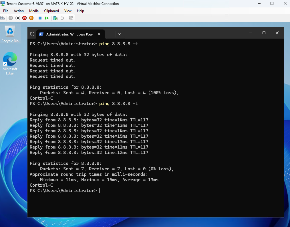
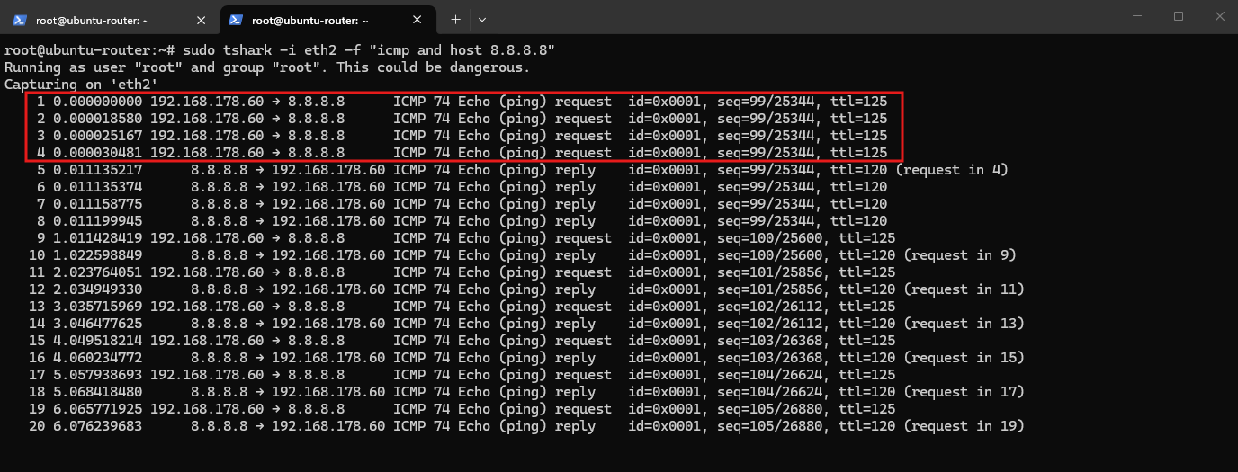
The capture on
eth2shows that the original tenant source address192.168.100.10is translated to the Ubuntu WAN address192.168.178.60, allowing the replies from8.8.8.8to return through the Ubuntu router and back to Tenant-CustomerB.
sudo tshark -i eth2 -f "icmp and host 8.8.8.8"
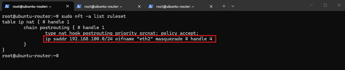
Before introducing VRFs, the nftables ruleset contains only the source NAT configuration created for the initial WAN connectivity test.
The postrouting rule masquerades traffic from 192.168.100.0/24 leaving through eth2, while no tenant-specific connection marking or routing rules are configured yet.
sudo nft -a list ruleset
Configuring VRFs for the Overlapping Tenant Networks
With the basic WAN routing path for CustomerB successfully established and verified, we can now introduce Linux VRFs. The goal is no longer to establish connectivity, but to create separate routing domains so that CustomerA and CustomerB can use identical IP address spaces without creating conflicting routes on the Ubuntu router.
We will place the CustomerB VLAN 41 transit interface into its own VRF and subsequently configure CustomerA with a separate VRF. Each tenant will therefore maintain an independent routing table, allowing both tenants to use the overlapping 192.168.100.0/24 network while still sharing the same Ubuntu router and WAN connection.
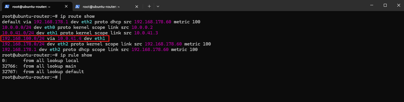
Before creating the VRFs, we capture the current main routing table and policy-routing rules as our baseline.
At this point, the CustomerB route 192.168.100.0/24 via 10.0.41.4 still resides in the main routing table, and no tenant-specific routing tables or policy rules exist yet.
ip route show
ip rule show
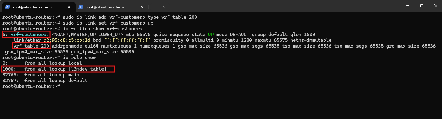
We now create a dedicated Linux VRF named vrf-customerb and associate it with routing table 200. The VRF acts as a separate Layer-3 routing domain, allowing CustomerB routes to be maintained independently from the main routing table and, later, from CustomerA.
sudo ip link add vrf-customerb type vrf table 200
sudo ip link set vrf-customerb up

Then verify it before we touch eth1:
ip -d link show vrf-customerb
ip rule show
The output confirms that
vrf-customerbis active and associated with routing table 200.Creating the VRF also automatically installs the
l3mdev-tablepolicy-routing rule at priority1000; because this rule appears immediately after creatingvrf-customerband is the kernel’s generic rule for L3 master devices such as VRFs, it directs VRF-associated traffic to the routing table assigned to that VRF, n our case, table 200.The remaining rules are the standard Linux policy-routing rules:
localhandles addresses belonging to the router itself,mainperforms normal routing using the main routing table, anddefaultis the final fallback lookup. Their priorities determine the lookup order, with lower numbers evaluated first.
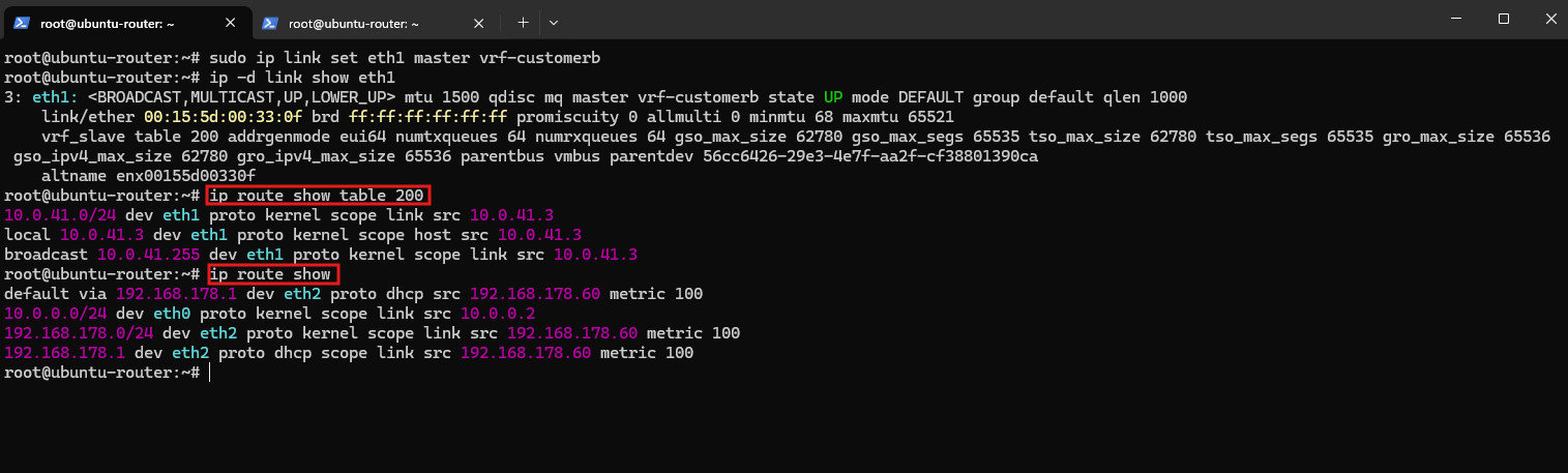
Next, we enslave the CustomerB transit interface eth1 to vrf-customerb. From this point, packets arriving through eth1 are associated with the CustomerB VRF, causing their routing decisions to use the VRF’s dedicated routing table 200.
sudo ip link set eth1 master vrf-customerb

Then let us immediately inspect what Linux did:
After enslaving
eth1tovrf-customerb, Linux automatically moves the directly connected10.0.41.0/24route from the main routing table into VRF table 200.The main table also no longer contains our temporary
192.168.100.0/24 via 10.0.41.4 dev eth1route because it was explicitly bound toeth1; unlike the directly connected route, this static route is not automatically recreated in table 200 and must be added there explicitly.
ip -d link show eth1
ip route show table 200
ip route show
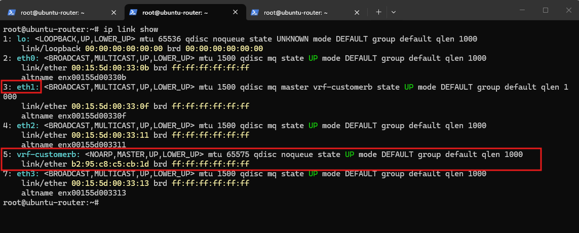
Note:
vrf-customerbis a virtual Layer-3 master interface to whicheth1is enslaved, associating traffic oneth1with the CustomerB routing domain and VRF routing table 200. It is not a VLAN subinterface, but the logical interface representing the isolated routing domain.
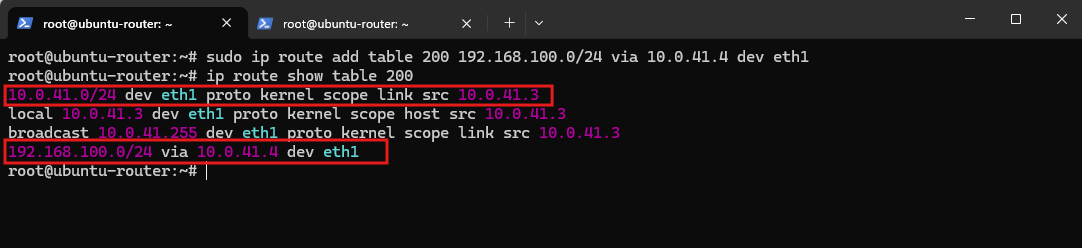
We now add the route to the CustomerB tenant network 192.168.100.0/24 to routing table 200, using the SDN Gateway L3 interface 10.0.41.4 as the next hop. This keeps the tenant route entirely within the vrf-customerb routing domain.
sudo ip route add table 200 192.168.100.0/24 via 10.0.41.4 dev eth1

Then we verify the complete CustomerB table:
The CustomerB routing table now contains both the directly connected
10.0.41.0/24transit network and the route to the tenant network192.168.100.0/24via the SDN Gateway at10.0.41.4.Both routes are therefore isolated within VRF table 200 and no longer exist in the main routing table.
ip route show table 200
Traffic through
eth0, the management interface on VLAN 10 (10.0.0.0/24), andeth2, the WAN interface connected to the Fritz!Box network (192.168.178.0/24), continues to use the main routing table, while traffic through the CustomerB transit interfaceeth1is routed independently through VRF table 200.
ip route show
ip link show
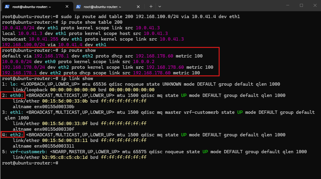
At this point, outbound traffic from Tenant-CustomerB works correctly. Packets enter the Ubuntu router through eth1, which is enslaved to vrf-customerb, so the initial route lookup is performed in VRF table 200.
Because table 200 contains no route for Internet destinations such as 8.8.8.8, the subsequent Linux policy-routing rules allow the lookup to continue with the main routing table, where the default route default via 192.168.178.1 dev eth2 is found.
The packet is therefore forwarded through the shared WAN interface eth2 and source-NATed from the tenant address 192.168.100.10 to the Ubuntu WAN address 192.168.178.60.
The return traffic also reaches eth2, and connection tracking (conntrack) correctly reverses the NAT translation from 192.168.178.60 back to the original tenant address 192.168.100.10.
Conntrack (connection tracking) is part of the Linux Netfilter framework and is automatically used by NAT to maintain the state of translated connections. It allows returning traffic to be matched to the original connection so that reverse NAT can restore the original source/destination addresses.
However, because the reply arrives through eth2, it is initially associated with the main routing domain, which has no route to the CustomerB 192.168.100.0/24 network. The packet therefore cannot be routed back through eth1 and the CustomerB transit network.
To solve this without adding overlapping tenant routes to the main routing table, we can combine connection tracking with Policy-Based Routing (PBR).
Conntrack allows us to preserve information about which tenant a connection belongs to, while PBR can use that information to direct returning packets into the appropriate tenant routing table, in this case VRF table 200 for CustomerB.
Policy-Based Routing (PBR) extends normal destination-based routing by allowing Linux to select a routing table according to additional packet properties, such as a firewall mark (fwmark). This becomes particularly useful with overlapping tenant networks because the destination address 192.168.100.10 alone cannot tell the router whether the packet belongs to CustomerA or CustomerB.
In our design, PBR is required only for the return path. Outbound CustomerB traffic already enters through
eth1and therefore automatically receives thevrf-customerbrouting context, whereas returning traffic arrives through the shared WAN interfaceeth2in the main routing domain.After conntrack performs the reverse NAT translation, PBR can use the preserved CustomerB connection mark to direct the routing lookup into VRF table 200, which contains the route back to
192.168.100.0/24through the SDN Gateway at10.0.41.4andeth1.
To preserve the tenant identity across the NAT connection, we now assign a conntrack mark to connections entering through the CustomerB transit interface eth1.
We use the value 200, matching the CustomerB VRF routing table number, which will later make the relationship between the connection mark and the corresponding routing table easy to identify.
The rule is evaluated for the original direction of connections entering through
eth1and stores the value200in the connection’s conntrack mark (ct mark). Unlike a normal packet mark, the conntrack mark belongs to the tracked connection and is therefore retained for the corresponding reply traffic.
sudo nft add table ip tenant-routing
sudo nft 'add chain ip tenant-routing prerouting { type filter hook prerouting priority mangle; policy accept; }'
sudo nft add rule ip tenant-routing prerouting iifname "eth1" ct direction original ct mark set 200
Next we need to restore the conntrack mark onto the packet mark (fwmark) for reply traffic. The conntrack mark persists with the connection, but Linux PBR evaluates the packet mark, so we copy ct mark → meta mark:
sudo nft add rule ip tenant-routing prerouting iifname "eth2" ct direction reply meta mark set ct mark

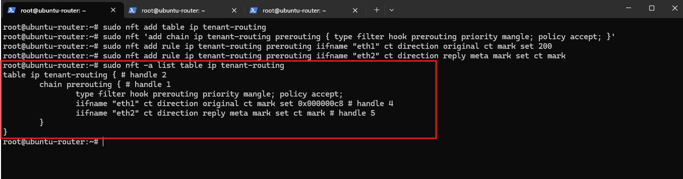
Then verify:
Returning packets arrive through the shared WAN interface
eth2. We therefore copy the connection’s conntrack mark (ct mark) to the packet’s firewall mark (meta mark/fwmark), making the preserved tenant identity available to Linux Policy-Based Routing for the subsequent route lookup.
sudo nft -a list table ip tenant-routing
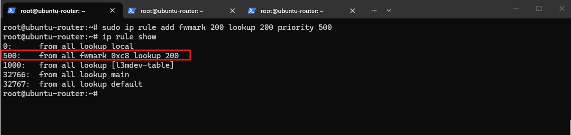
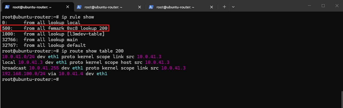
We now add a Policy-Based Routing rule that directs packets carrying fwmark 200 to the CustomerB VRF routing table 200.
The rule uses priority
500, placing it before the automatically createdl3mdev-tablerule at priority1000, so marked return traffic is routed through CustomerB’s VRF table before the normal routing rules are evaluated.
sudo ip rule add fwmark 200 lookup 200 priority 500

Verify it:
ip rule show
We now verify the PBR rule and VRF table together:
The output confirms that the new PBR rule is evaluated before the generic
l3mdevrule and directs packets carryingfwmark 200to routing table 200.This table contains the required return route to the CustomerB network
192.168.100.0/24through the SDN Gateway at10.0.41.4viaeth1.
ip rule show
ip route show table 200
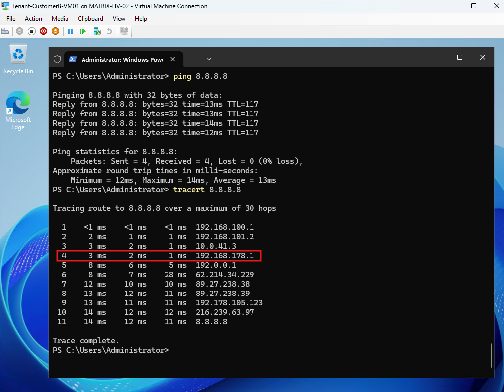
The final ping and tracert confirm successful Internet connectivity from Tenant-CustomerB-VM01.
The trace clearly shows the complete path through the HNV virtual gateway (
192.168.100.1) → SDN Gateway (192.168.101.2) → Ubuntu CustomerB transit interface (10.0.41.3) → Fritz!Box (192.168.178.1) → Internet, confirming that the VRF, PBR, conntrack-based return routing, and NAT configuration are working together correctly.
Note: The VRF, policy-based routing, and nftables configuration created so far exists only in the running Linux networking configuration and is therefore not persistent across reboots.
We will make the complete configuration persistent after CustomerA has also been migrated and both tenant networks have been successfully tested together.
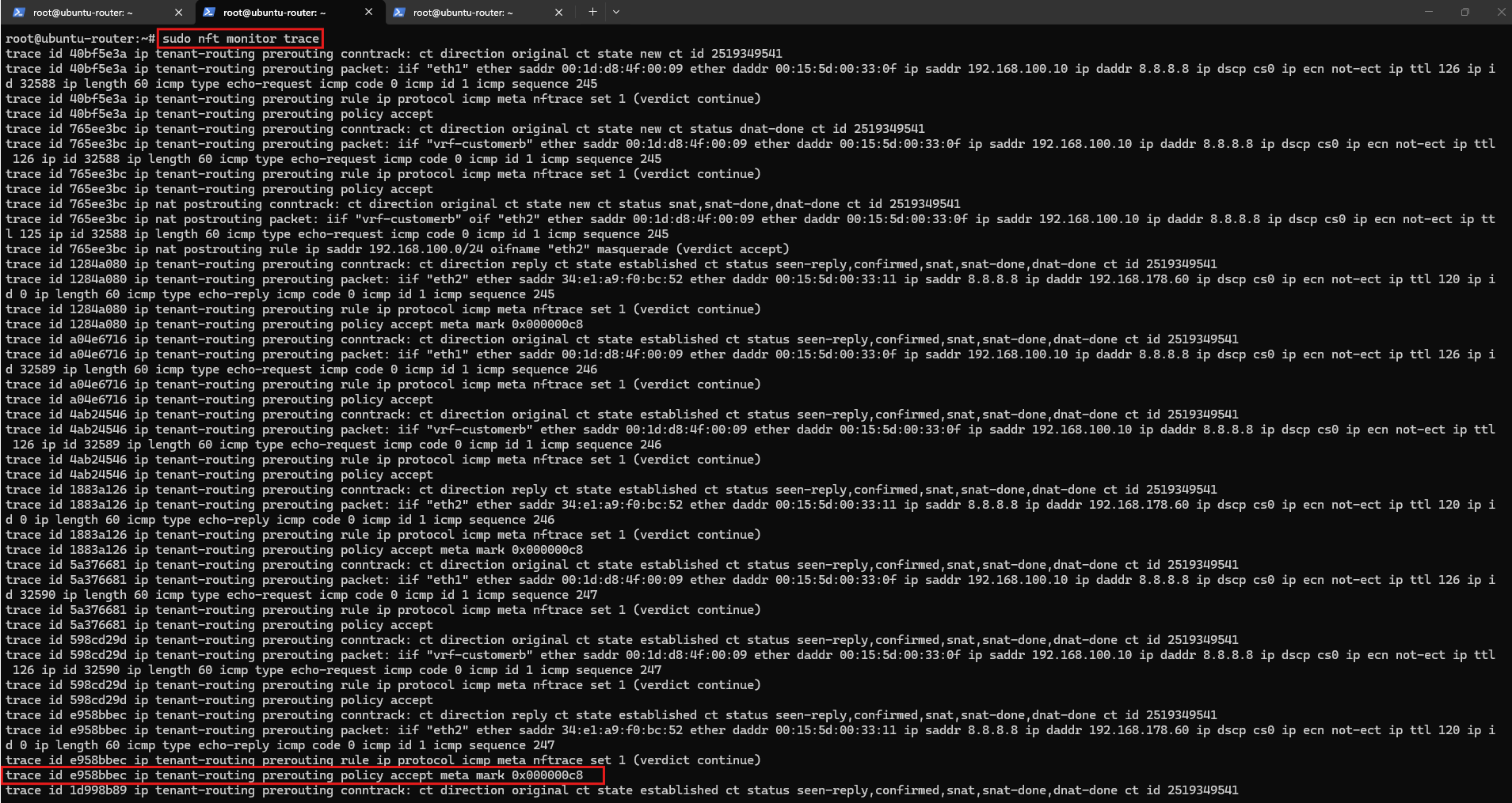
Using nftables packet tracing, we can verify the tenant marking directly in the Linux networking stack.
The reply from
8.8.8.8arrives through the shared WAN interfaceeth2, and the trace showsmeta mark 0x000000c8(200decimal), confirming that the CustomerB conntrack mark is successfully restored as the packetfwmarkused by our PBR rule.
The resulting architecture extends HNV tenant isolation beyond the Microsoft SDN fabric, using separate VRFs and PBR while allowing both overlapping tenant networks to share the same WAN connection.
                  Shared WAN Ubuntu Router
                  eth2 / 192.168.178.0/24
                             |
                       NAT / Conntrack
                             |
                   +---------+---------+
                   |                   |
             fwmark 100           fwmark 200
               PBR                   PBR
                   |                   |
          VRF CustomerA         VRF CustomerB
            table 100             table 200
                   |                   |
                VLAN40              VLAN41
                   |                   |
             SDN Gateway          SDN Gateway
                   |                   |
          Tenant-CustomerA      Tenant-CustomerB
           192.168.100.0/24     192.168.100.0/24
With the complete VRF, conntrack, PBR, and NAT path now working for Tenant-CustomerB, we can apply the same architecture to Tenant-CustomerA.
CustomerA currently still uses VLAN 40 and the external pfSense router for WAN access; we will migrate this transit connection to the Ubuntu router, place it in a separate CustomerA VRF using routing table 100, and use the same connection-marking and PBR mechanism while both tenants continue to use the overlapping 192.168.100.0/24 address space.
Migrating Tenant-CustomerA from pfSense to the Ubuntu VRF Router
Tenant-CustomerA currently uses its existing VLAN 40 L3 transit network to reach the external pfSense router at 10.0.40.1.
We will now migrate this external routing endpoint to the Ubuntu router and place the CustomerA transit interface in a dedicated vrf-customera using routing table 100, allowing both tenants to share the same WAN while retaining completely independent routing domains.
Before migrating Tenant-CustomerA, we verify its existing Internet connectivity through pfSense.
The trace shows the current path through the HNV virtual gateway (
192.168.100.1) → SDN Gateway (192.168.101.3) → pfSense on the VLAN 40 transit network (10.0.40.1) → Fritz!Box (192.168.178.1) → Internet, providing a clear baseline for comparison after moving CustomerA to the Ubuntu VRF router.
Migrating the CustomerA VLAN 40 Transit Endpoint to Ubuntu
Before configuring CustomerA on the Ubuntu router, we first disable the existing SDNL3TRANSIT interface on pfSense, which currently owns the transit address 10.0.40.1.
The same address will be reused by the new Ubuntu transit interface. However, 10.0.40.1 is currently also configured as the default gateway of the Network Controller logical subnet, causing Network Controller to reserve the address.
Note: The Network Controller logical subnet
SDN-L3-Transit-Subnetrepresents the VLAN 40 transit network10.0.40.0/24and currently has10.0.40.1configured as its default gateway.Before onboarding the Ubuntu interface, we change the logical subnet’s default gateway from
10.0.40.1to10.0.40.4, releasing10.0.40.1for assignment to the NC-managed Ubuntu interface.In this lab, there is no router or other host using
10.0.40.4. The address is configured only as the logical subnet’sDefaultGatewaybecause Network Controller requires a gateway value for this L3 transit subnet; it is not part of the actual CustomerA forwarding path. The SDN L3 connection instead explicitly uses10.0.40.2as the SDN Gateway address and10.0.40.1as the Ubuntu peer, so the logical subnet’s default gateway is not actually required for forwarding traffic in our lab topology.
We update the existing logical subnet and change its default gateway from 10.0.40.1 to 10.0.40.4:
$subnetA = Get-NetworkControllerLogicalSubnet -ConnectionUri $uri -LogicalNetworkId "SDN-L3-Transit" -ResourceId "SDN-L3-Transit-Subnet"
$subnetA.Properties.DefaultGateways = @("10.0.40.4")
New-NetworkControllerLogicalSubnet -ConnectionUri $uri -LogicalNetworkId "SDN-L3-Transit" -ResourceId "SDN-L3-Transit-Subnet" -Properties $subnetA.Properties -Force
$subnetA.Properties | Format-List VlanID,AddressPrefix,DefaultGateways,ProvisioningState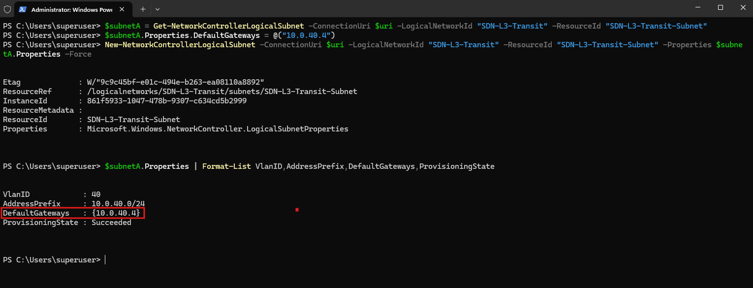
Network Controller now reserves
10.0.40.4as the logical subnet’s default gateway, releasing10.0.40.1so that it can be assigned to the new Ubuntu transit interface.
Next, we add a dedicated network adapter to Ubuntu-Router connected to the SDN-managed vSwitch-VM:
Name:     Transit-CustomerA
vSwitch:  vSwitch-VM
VLAN:     40
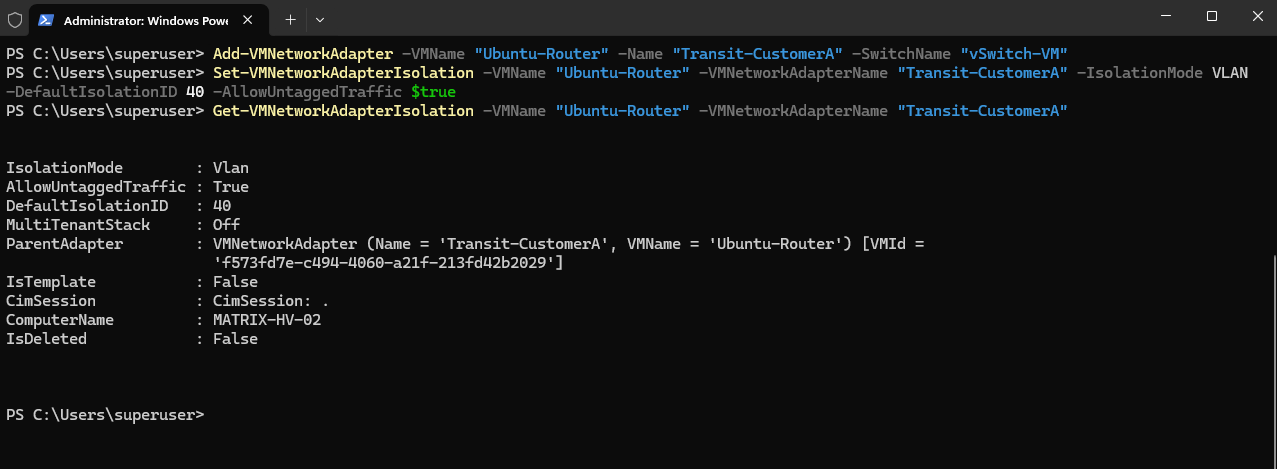
Add-VMNetworkAdapter -VMName "Ubuntu-Router" -Name "Transit-CustomerA" -SwitchName "vSwitch-VM"
Set-VMNetworkAdapterIsolation -VMName "Ubuntu-Router" -VMNetworkAdapterName "Transit-CustomerA" -IsolationMode VLAN -DefaultIsolationID 40 -AllowUntaggedTraffic $true

Then verify:
The new
Transit-CustomerAadapter is now connected to the SDN-managedvSwitch-VMand assigned to VLAN 40 using Hyper-V network isolation.
Get-VMNetworkAdapterIsolationconfirmsDefaultIsolationID 40andAllowUntaggedTraffic True, matching the existing CustomerA L3 transit network.
Get-VMNetworkAdapterIsolation -VMName "Ubuntu-Router" -VMNetworkAdapterName "Transit-CustomerA"
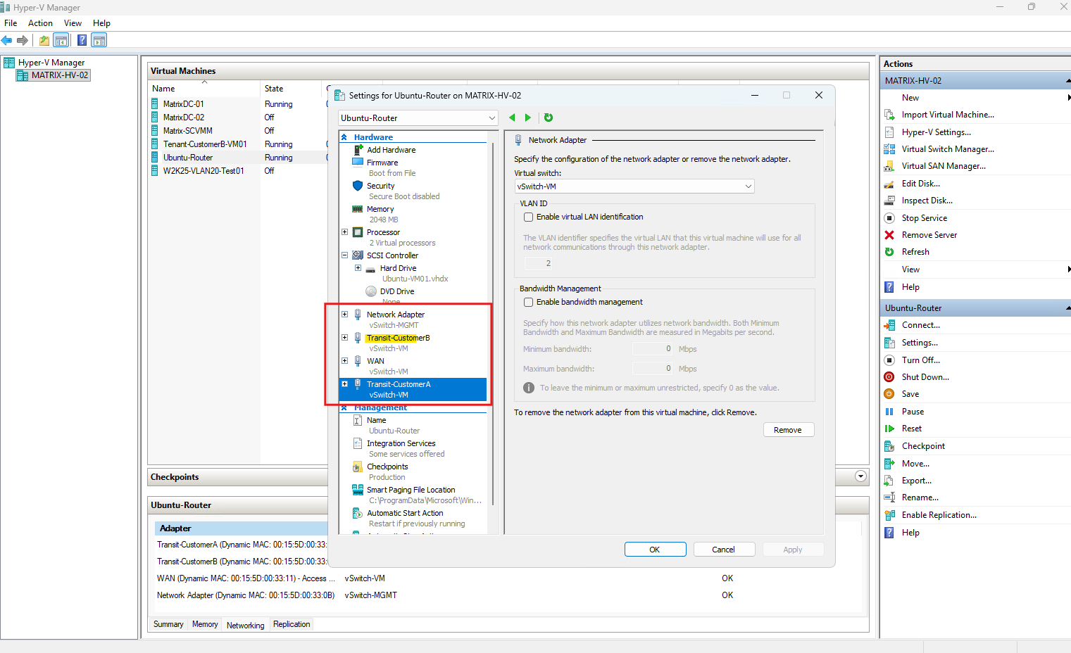
As with the CustomerB transit interface, this adapter will later be onboarded with Network Controller and assigned the Microsoft SDN Port Profile before becoming part of the dedicated CustomerA VRF.
Ubuntu detects the newly added CustomerA transit adapter as eth3, with MAC address 00:15:5d:00:33:13.
This interface will become the VLAN 40 endpoint for the CustomerA transit network and will later be enslaved to the dedicated CustomerA VRF.
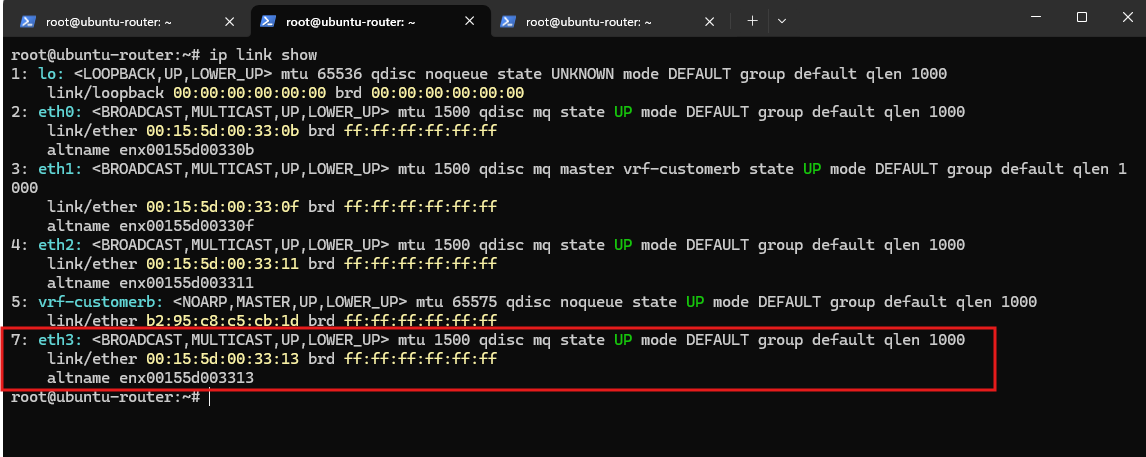
We now configure the new eth3 CustomerA transit interface with the address 10.0.40.4/24. The former pfSense address 10.0.40.1 cannot be reused because it is configured as the default gateway of the Network Controller logical subnet and is therefore reserved by Network Controller.
Matching the interface by its MAC address ensures that the configuration remains associated with the correct Hyper-V network adapter.
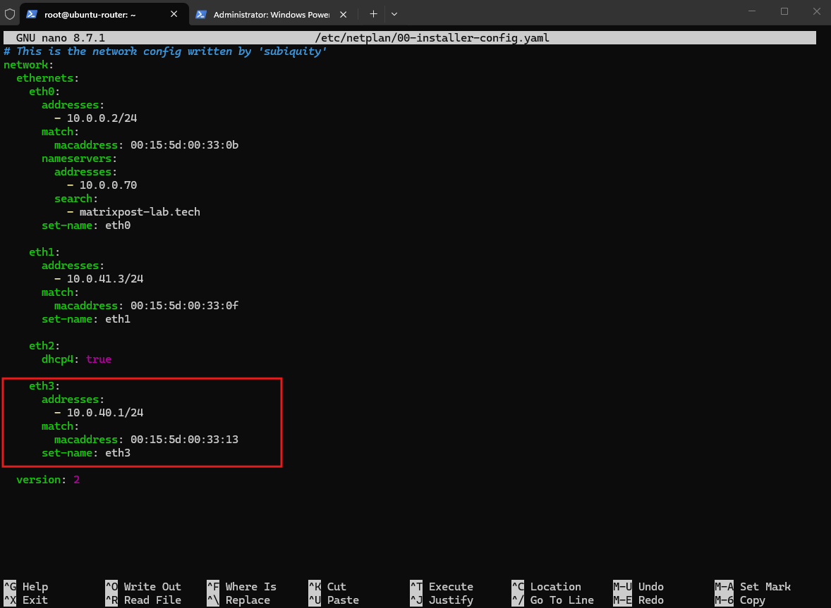
We then apply the updated Netplan configuration and verify that eth3 has received the expected address.
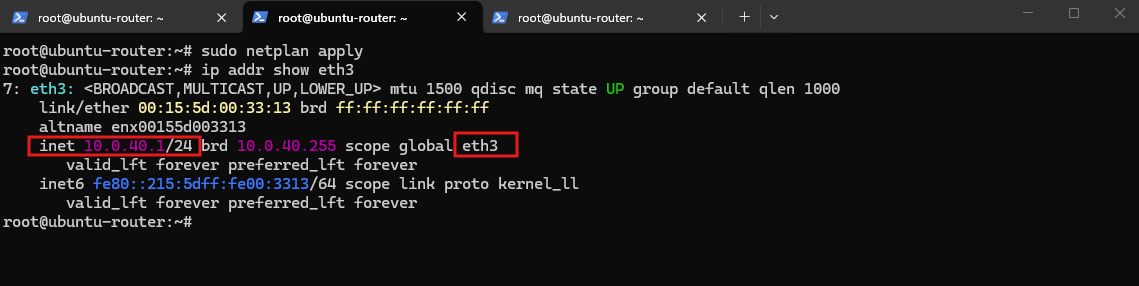
After applying the updated Netplan configuration,
ip addr show eth3confirms that the new CustomerA transit interface is up and configured with10.0.40.1/24, successfully taking over the former pfSense endpoint on the VLAN 40 transit network.
sudo netplan apply
ip addr show eth3
Onboarding the CustomerA Transit Interface with Network Controller
Because Transit-CustomerA is connected to the SDN-managed vSwitch-VM, we now register the new interface with Network Controller, following the same onboarding process already used for CustomerB.
The Network Controller NIC will be associated with the existing SDN-L3-Transit-Subnet (10.0.40.0/24, VLAN 40) and the static transit address 10.0.40.1, which Ubuntu has taken over from pfSense.
After onboarding, we will apply the resulting Network Controller NIC InstanceId as the Microsoft SDN Port Profile ID to the Hyper-V adapter, allowing the interface to pass traffic correctly through the VFP policies on vSwitch-VM.
We now create a Network Controller network interface resource for the Ubuntu CustomerA transit adapter.
Unlike CustomerB, we use a static allocation of 10.0.40.1, because Ubuntu is deliberately taking over the existing pfSense endpoint while the SDN Gateway remains at 10.0.40.2.
Because the Network Controller NIC will use a static MAC address, we also configure the Hyper-V Transit-CustomerA adapter with the same static MAC address 00155D003313 before creating the Network Controller resource.
Stop-VM -Name "Ubuntu-Router"
Set-VMNetworkAdapter -VMName "Ubuntu-Router" -Name "Transit-CustomerA" -StaticMacAddress "00155D003313"
Start-VM -Name "Ubuntu-Router"
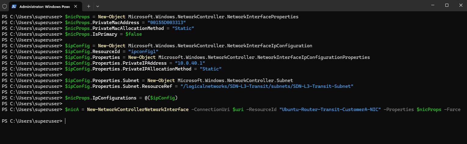
We now create the Network Controller NIC resource using the static MAC address 00155D003313 and static IP address 10.0.40.1, associating it with the existing SDN-L3-Transit-Subnet on VLAN 40.
$nicProps = New-Object Microsoft.Windows.NetworkController.NetworkInterfaceProperties
$nicProps.PrivateMacAddress = "00155D003313"
$nicProps.PrivateMacAllocationMethod = "Static"
$nicProps.IsPrimary = $false

$ipConfig = New-Object Microsoft.Windows.NetworkController.NetworkInterfaceIpConfiguration
$ipConfig.ResourceId = "ipconfig1"
$ipConfig.Properties = New-Object Microsoft.Windows.NetworkController.NetworkInterfaceIpConfigurationProperties
$ipConfig.Properties.PrivateIPAddress = "10.0.40.1"
$ipConfig.Properties.PrivateIPAllocationMethod = "Static"

$ipConfig.Properties.Subnet = New-Object Microsoft.Windows.NetworkController.Subnet
$ipConfig.Properties.Subnet.ResourceRef = "/logicalnetworks/SDN-L3-Transit/subnets/SDN-L3-Transit-Subnet"

$nicProps.IpConfigurations = @($ipConfig)

$nicA = New-NetworkControllerNetworkInterface -ConnectionUri $uri -ResourceId "Ubuntu-Router-Transit-CustomerA-NIC" -Properties $nicProps -Force
Now we verify the resource and get the new InstanceId:
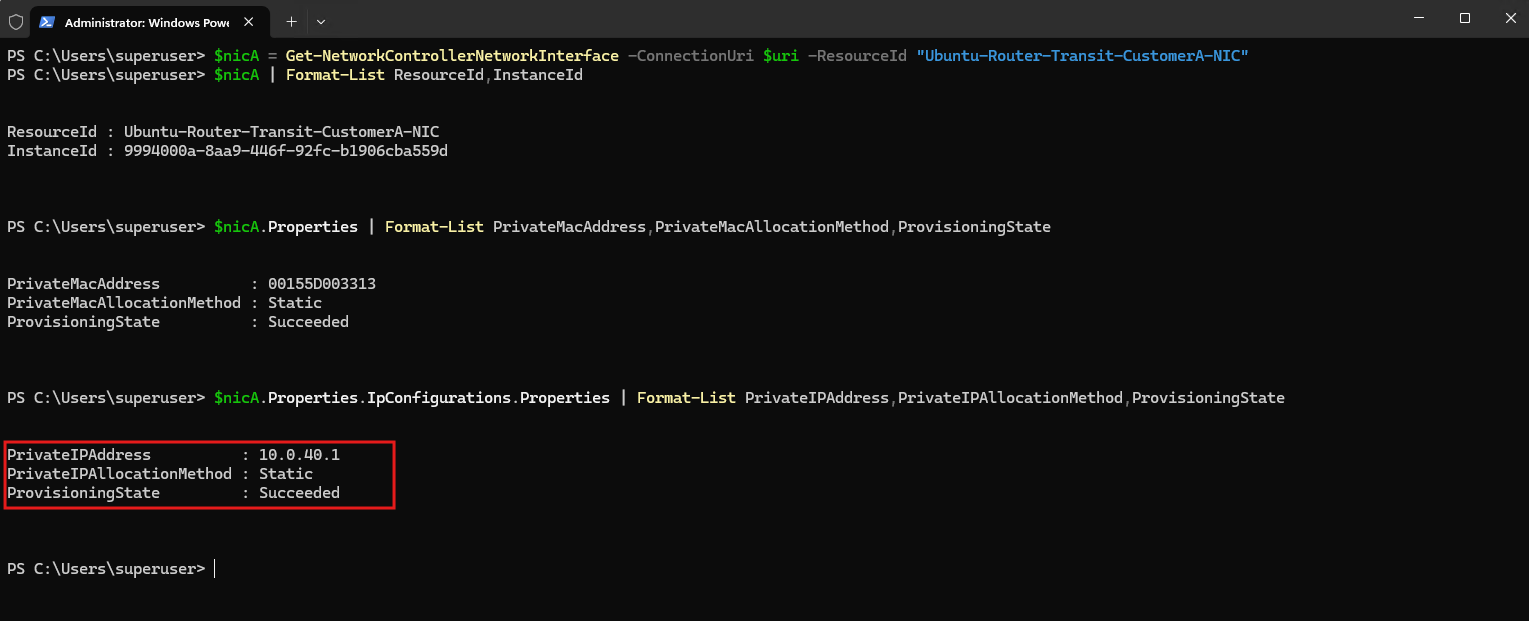
The Network Controller NIC and its IP configuration both show
ProvisioningState: Succeeded, confirming that the CustomerA transit interface has been successfully registered with the static address10.0.40.1.The resulting NIC InstanceId
9994000a-8aa9-446f-92fc-b1906cba559dwill now be used as the Microsoft SDN Port Profile ID on the corresponding Hyper-V adapter.
$nicA = Get-NetworkControllerNetworkInterface -ConnectionUri $uri -ResourceId "Ubuntu-Router-Transit-CustomerA-NIC"
$nicA | Format-List ResourceId,InstanceId
$nicA.Properties | Format-List PrivateMacAddress,PrivateMacAllocationMethod,ProvisioningState
$nicA.Properties.IpConfigurations.Properties | Format-List PrivateIPAddress,PrivateIPAllocationMethod,ProvisioningState
Next we apply the Microsoft SDN Port Profile to the Hyper-V Transit-CustomerA adapter using the Network Controller NIC InstanceId 9994000a-8aa9-446f-92fc-b1906cba559d.
The Network Controller NIC InstanceId now becomes the SDN Port Profile ID, linking the physical Hyper-V VM adapter with the corresponding Network Controller resource and allowing VFP to apply the SDN configuration to the port.
Stop-VM -ComputerName "MATRIX-HV-02" -Name "Ubuntu-Router"

Invoke-Command -ComputerName "MATRIX-HV-02" -ScriptBlock {
    $nic = Get-VMNetworkAdapter -VMName "Ubuntu-Router" -Name "Transit-CustomerA"

    $FeatureId = "9940cd46-8b06-43bb-b9d5-93d50381fd56"
    $PortProfile = Get-VMSystemSwitchExtensionPortFeature -FeatureId $FeatureId

    $PortProfile.SettingData.ProfileId = "{9994000a-8aa9-446f-92fc-b1906cba559d}"
    $PortProfile.SettingData.ProfileData = 2
    $PortProfile.SettingData.ProfileName = "Microsoft SDN Port"
    $PortProfile.SettingData.VendorId = "{1FA41B39-B444-4E43-B35A-E1F7985FD548}"

    Add-VMSwitchExtensionPortFeature -VMNetworkAdapter $nic -VMSwitchExtensionFeature $PortProfile
}

Start-VM -ComputerName "MATRIX-HV-02" -Name "Ubuntu-Router"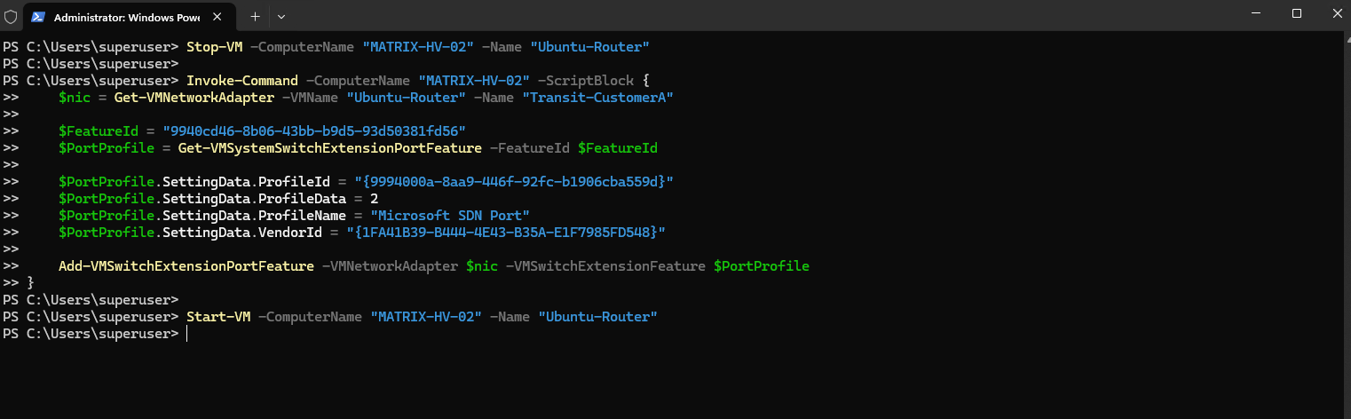
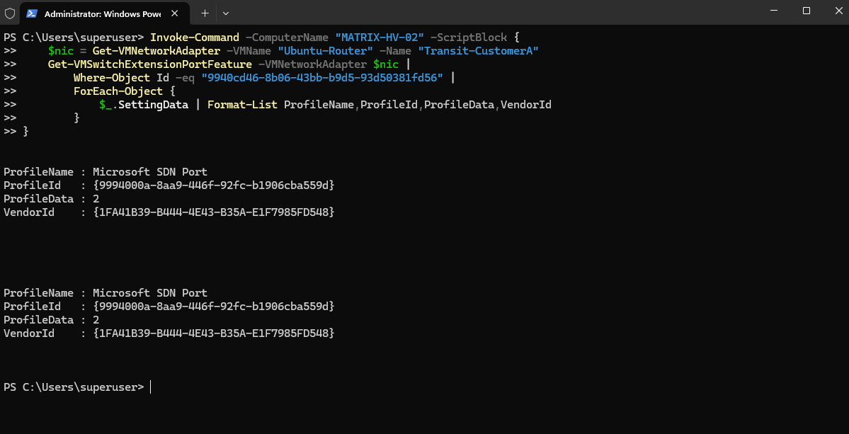
Verification confirms that the Microsoft SDN Port Profile is attached to the CustomerA Hyper-V adapter with the Network Controller NIC InstanceId 9994000a-8aa9-446f-92fc-b1906cba559d as its ProfileId.
The adapter is therefore now associated with its Network Controller resource and can be processed by the SDN/VFP datapath.
Invoke-Command -ComputerName "MATRIX-HV-02" -ScriptBlock {
    $nic = Get-VMNetworkAdapter -VMName "Ubuntu-Router" -Name "Transit-CustomerA"
    Get-VMSwitchExtensionPortFeature -VMNetworkAdapter $nic |
        Where-Object Id -eq "9940cd46-8b06-43bb-b9d5-93d50381fd56" |
        ForEach-Object {
            $_.SettingData | Format-List ProfileName,ProfileId,ProfileData,VendorId
        }
}
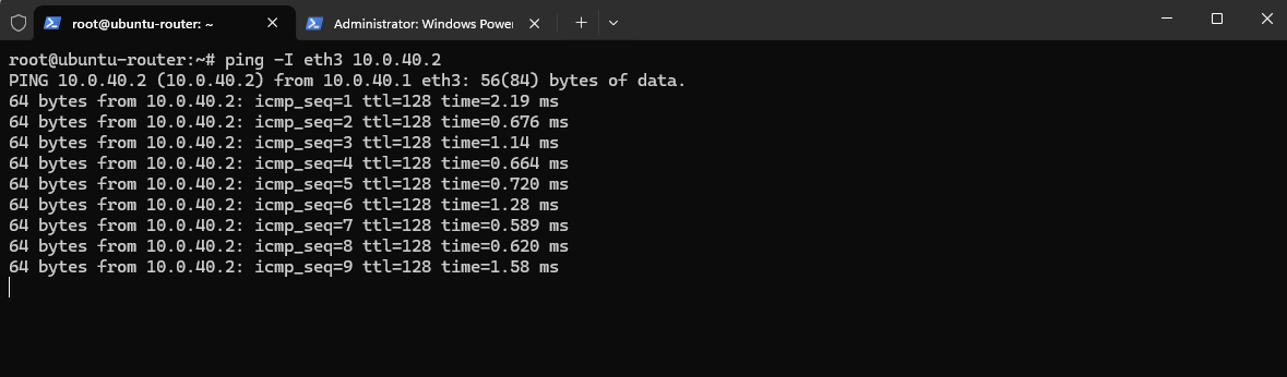
A final connectivity test confirms that the new Ubuntu CustomerA transit interface eth3 (10.0.40.1) can successfully reach the SDN Gateway at 10.0.40.2 across VLAN 40.
This verifies that the Network Controller onboarding, SDN Port Profile, VLAN configuration, and VFP datapath are working correctly.
ping -I eth3 10.0.40.2
Configuring the CustomerA VRF
With the VLAN 40 transit path working, we can now create a second VRF for CustomerA using routing table 100.
This provides CustomerA with its own routing domain, separate from CustomerB’s table 200.
sudo ip link add vrf-customera type vrf table 100
sudo ip link set vrf-customera up
sudo ip link set eth3 master vrf-customera

Then we add the CustomerA tenant route through its existing SDN Gateway:
sudo ip route add table 100 192.168.100.0/24 via 10.0.40.2 dev eth3

Verify:
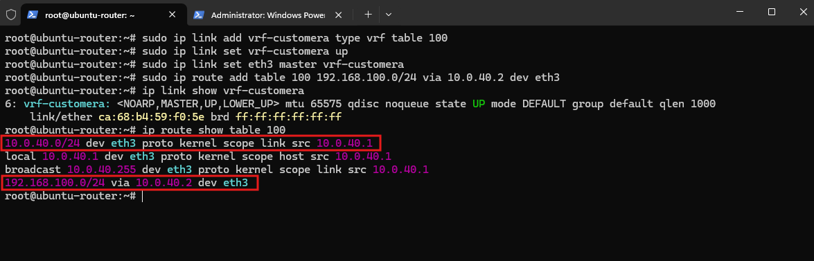
Then validate and apply the conThe output confirms that
vrf-customerais active andeth3now belongs to routing table 100. The table contains the connected VLAN 40 transit network10.0.40.0/24and the CustomerA return route192.168.100.0/24 via 10.0.40.2 dev eth3, keeping CustomerA’s overlapping tenant prefix completely separate from CustomerB’s identical route in table 200.
ip link show vrf-customera
ip route show table 100
Next we extend our existing conntrack/PBR configuration to CustomerA.
CustomerA connections entering through eth3 receive conntrack mark 100, matching VRF table 100:
The existing rule for return traffic arriving through the shared WAN interface
eth2restores the connection’sct markas the packetfwmark, and therefore works for both CustomerA and CustomerB:
sudo nft add rule ip tenant-routing prerouting iifname "eth3" ct direction original ct mark set 100

We then add a PBR rule directing packets marked with fwmark 100 to CustomerA’s routing table 100:
sudo ip rule add fwmark 100 lookup 100 priority 400

Verify:
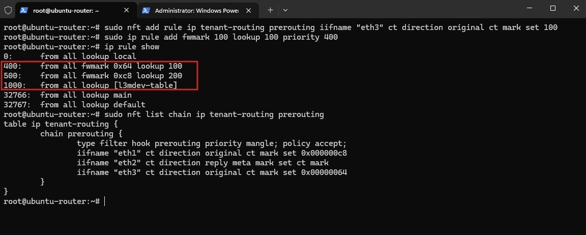
The output confirms that both tenant-specific PBR rules are active. CustomerA traffic marked
0x64(100) is directed to routing table 100, while CustomerB traffic marked0xc8(200) is directed to routing table 200; both rules are evaluated before the genericl3mdevrule.The nftables configuration likewise assigns conntrack mark 100 to CustomerA connections entering through
eth3and mark 200 to CustomerB connections entering througheth1, while the sharedeth2rule restores the appropriate connection mark on returning WAN traffic.
ip rule show
sudo nft list chain ip tenant-routing prerouting
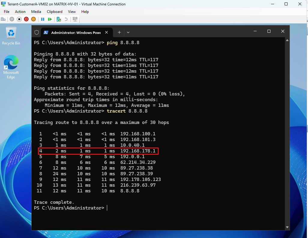
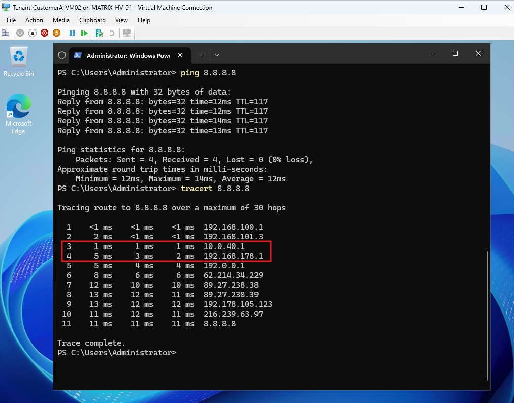
The final connectivity test confirms that both CustomerA and CustomerB can access the Internet simultaneously while using the same overlapping 192.168.100.0/24 tenant network.
CustomerA is independently routed through VRF table 100 and VLAN 40, while CustomerB uses VRF table 200 and VLAN 41, with both tenants sharing the same Ubuntu router and WAN interface.
CustomerA’s
tracertalso confirms the expected path through the HNV virtual gateway (192.168.100.1) → SDN Gateway (192.168.101.3) → Ubuntu CustomerA transit interface (10.0.40.1) → Fritz!Box (192.168.178.1) → Internet.
With both overlapping tenant networks now successfully routed through their respective VRFs and sharing the same WAN connection, the functional design is complete.
However, the VRF interfaces, tenant routes, policy-based routing rules, and nftables configuration created so far exist only in the running Linux configuration and would be lost after a reboot.
As the final configuration step, we will therefore make the complete CustomerA and CustomerB VRF routing configuration persistent, ensuring that both isolated routing domains and their shared WAN connectivity are automatically restored when the Ubuntu router starts.
Making the VRF and Tenant Routing Configuration Persistent
Up to this point, the VRFs, interface assignments, routing rules, and related network configuration were created manually to demonstrate and verify the tenant routing design. The configuration is fully functional, but most of these changes exist only in the running Linux networking state and would therefore be lost after a reboot.
The final step is to make the Ubuntu router configuration persistent. This ensures that the VRF devices, tenant-facing interfaces, routing tables, policy-routing rules, and required forwarding configuration are automatically restored when the system starts.
First, I will extend the existing Netplan configuration to create the two VRF devices and assign the corresponding SDN transit interfaces to them.
Tenant 1 uses eth3 with 10.0.40.1/24, while Tenant 2 uses eth1 with 10.0.41.3/24. Each VRF is associated with its own Linux routing table, keeping both tenant routing contexts separated.
network:
  ethernets:
    eth0:
      addresses:
        - 10.0.0.2/24
      match:
        macaddress: 00:15:5d:00:33:0b
      nameservers:
        addresses:
          - 10.0.0.70
        search:
          - matrixpost-lab.tech
      set-name: eth0

    eth1:
      addresses:
        - 10.0.41.3/24
      match:
        macaddress: 00:15:5d:00:33:0f
      set-name: eth1

    eth2:
      dhcp4: true

    eth3:
      addresses:
        - 10.0.40.1/24
      match:
        macaddress: 00:15:5d:00:33:13
      set-name: eth3

  vrfs:
    vrf-tenant1:
      table: 1001
      interfaces:
        - eth3

    vrf-tenant2:
      table: 1002
      interfaces:
        - eth1

  version: 2
The
vrfssection createsvrf-tenant1andvrf-tenant2and associates them with routing tables1001and1002.Assigning
eth3andeth1to these VRFs moves the respective tenant transit networks into their isolated routing contexts instead of using the globalmainrouting table.
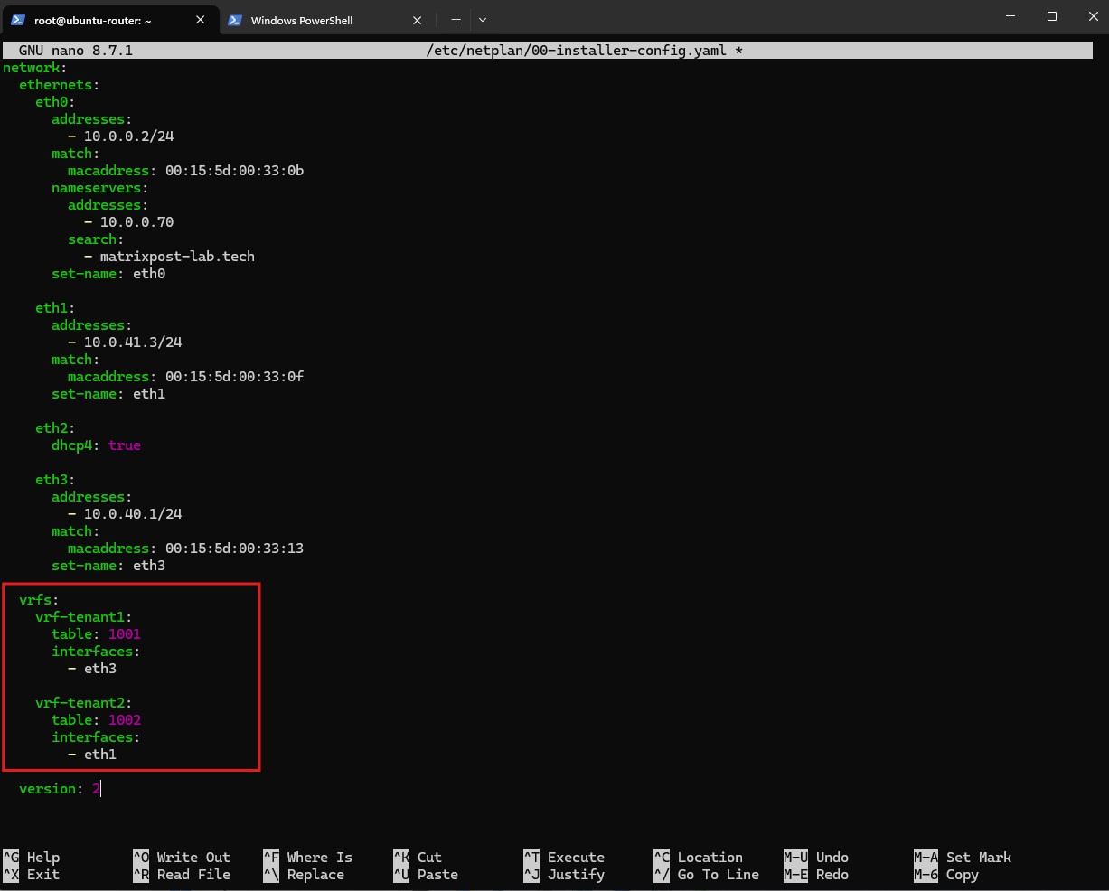
Before applying the configuration, we can first validate the Netplan configuration:
netplan generate
If no errors are returned, we can apply it:
netplan apply

Persisting IP Forwarding
The VRFs and their routing tables can then be verified with:
As shown above, both VRF devices are now active. The directly connected SDN transit networks are automatically installed in their respective VRF routing tables:
10.0.40.0/24in table1001for Tenant 1 and10.0.41.0/24in table1002for Tenant 2.
ip link show type vrf
ip route show table 1001
ip route show table 1002
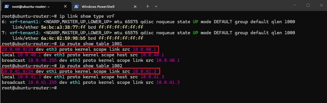
Because both tenants use the same 192.168.100.0/24 address space, the same destination prefix can exist independently in both VRF routing tables. Each route points toward the corresponding Hyper-V SDN transit next hop.
Add the tenant routes to the respective transit interfaces in /etc/netplan/00-installer-config.yaml and explicitly assign them to the corresponding VRF routing table.
eth1:
  addresses:
    - 10.0.41.3/24
  match:
    macaddress: 00:15:5d:00:33:0f
  set-name: eth1
  routes:
    - to: 192.168.100.0/24
      via: 10.0.41.4
      table: 1002

eth3:
  addresses:
    - 10.0.40.1/24
  match:
    macaddress: 00:15:5d:00:33:13
  set-name: eth3
  routes:
    - to: 192.168.100.0/24
      via: 10.0.40.2
      table: 1001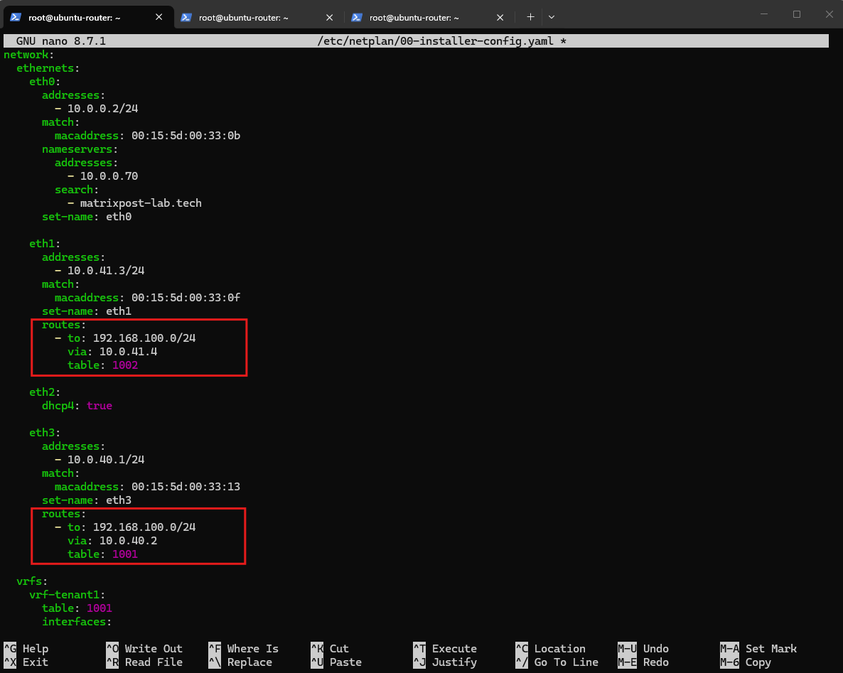
Then validate and apply the configuration:
netplan generate
netplan apply

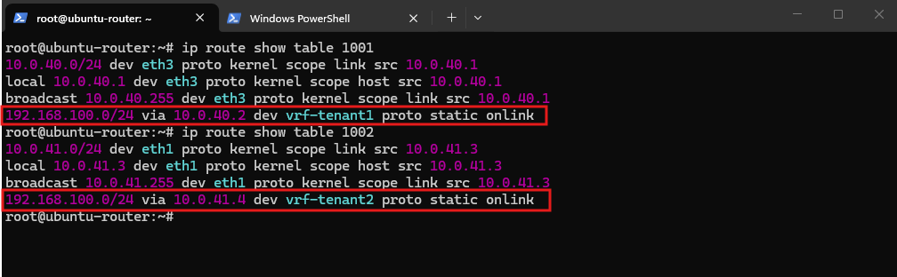
Verify both routing tables:
Both VRF routing tables now contain a route to the identical
192.168.100.0/24tenant prefix. Because the routes reside in separate VRF routing tables, there is no routing conflict: Tenant 1 reaches the network through the Tenant 1 SDN transit path, while Tenant 2 reaches the same IP prefix through its own isolated transit path.
ip route show table 1001
ip route show table 1002
Persisting IPv4 Routing
The VRF devices and tenant-specific routes are now defined persistently through Netplan. However, the Ubuntu system also needs IPv4 forwarding enabled after every reboot to continue routing traffic between the tenant networks and the external network.
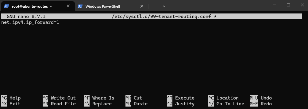
Create a dedicated sysctl configuration file:
nano /etc/sysctl.d/99-tenant-routing.conf
Add:
net.ipv4.ip_forward=1
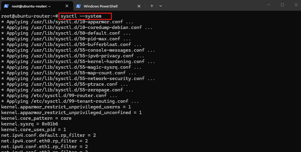
Apply the configuration:
sysctl --system
And verify the setting:
sysctl net.ipv4.ip_forward

Persisting the nftables Configuration
The tenant routing design also relies on nftables for NAT and connection tracking. The rules created interactively with the nft command are part of the runtime ruleset and are lost after a reboot. I therefore store the required rules in /etc/nftables.conf.
First, make sure nftables is installed and enabled:
systemctl enable nftables

Edit the configuration:
nano /etc/nftables.conf
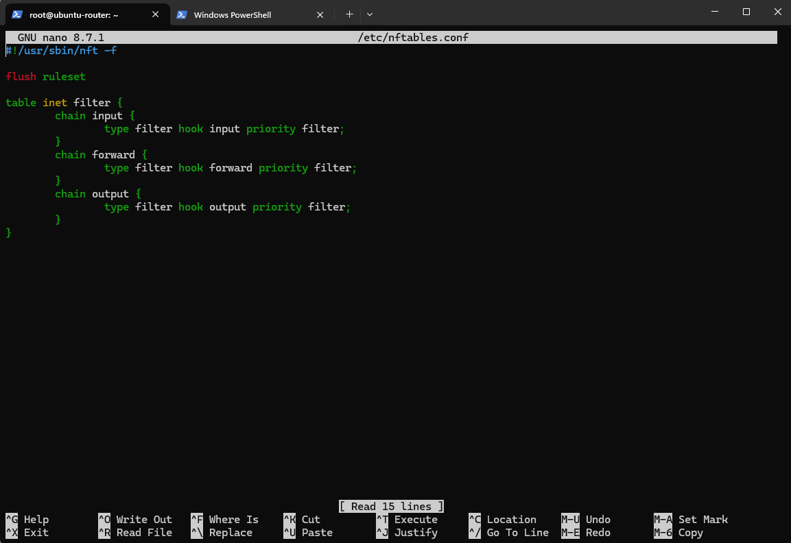
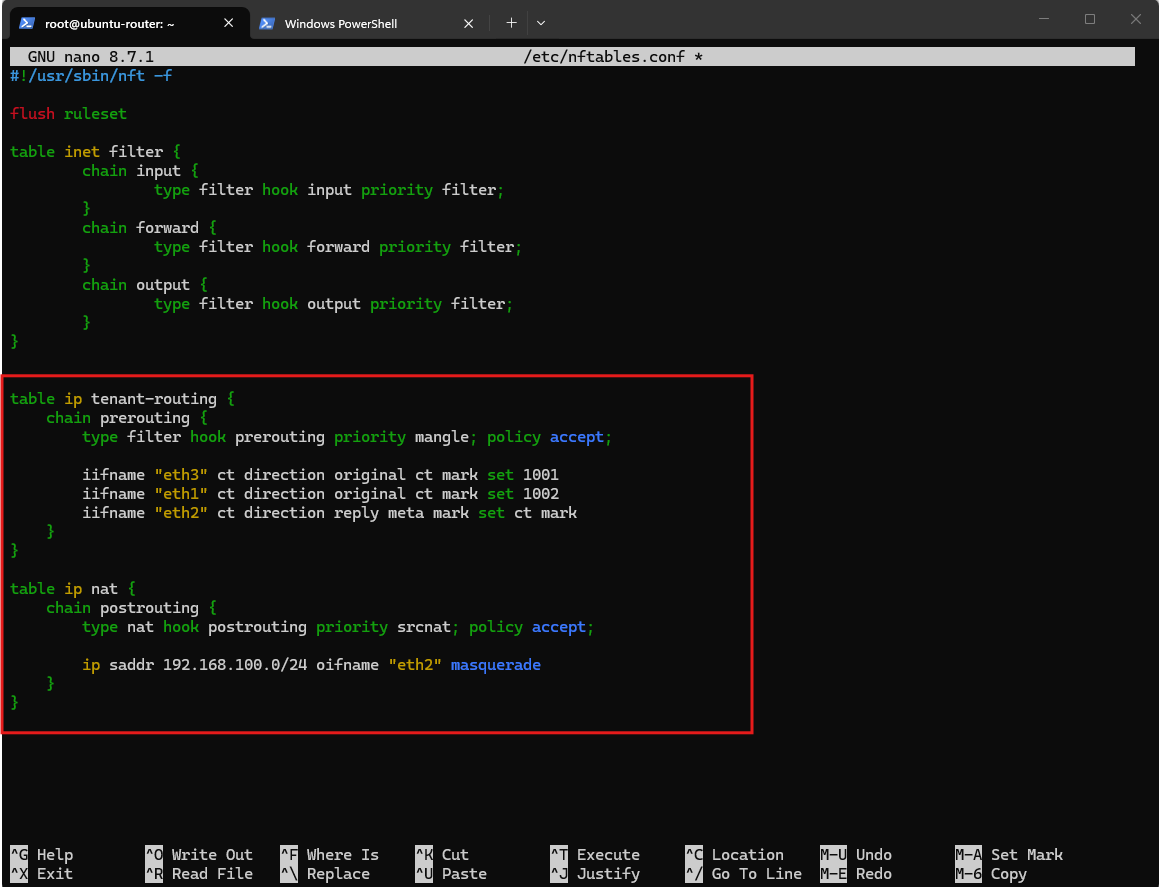
We append our two tables below the default configaration above.
We don’t add another
flush ruleset!When nftables loads the file, it clears the old runtime rules and then reconstructs the complete ruleset, including the existing default filter table plus our tenant-routing and NAT tables.
#!/usr/sbin/nft -f

flush ruleset

table ip tenant-routing {
    chain prerouting {
        type filter hook prerouting priority mangle; policy accept;

        iifname "eth3" ct direction original ct mark set 1001
        iifname "eth1" ct direction original ct mark set 1002
        iifname "eth2" ct direction reply meta mark set ct mark
    }
}

table ip nat {
    chain postrouting {
        type nat hook postrouting priority srcnat; policy accept;

        ip saddr 192.168.100.0/24 oifname "eth2" masquerade
    }
}
Then we save and check the complete file syntactically:
The configuration can be validated with
nft -c -f /etc/nftables.confbefore it is loaded. No output indicates that the ruleset passed the syntax check. The nftables service is then restarted and enabled to automatically restore the configuration during system startup.
nft -c -f /etc/nftables.conf

Persisting the Policy Routing Rules
The nftables configuration restores the tenant-specific connection mark to returning packets. Linux policy routing must then use this firewall mark to select the corresponding tenant routing table.
For our persistent configuration, the mappings are:
fwmark 1001 → table 1001
fwmark 1002 → table 1002
Since these policy-routing rules must be restored after Netplan has created the VRFs and their corresponding routing tables, we will use a small systemd oneshot service to make them persistent.
Netplan can persist the VRFs and their routes, but its
routing-policyconfiguration requires a source or destination prefix and therefore cannot directly express the firewall-mark-only rules used here. We therefore use a small systemd oneshot service to restore the twofwmarkpolicy-routing rules after the network configuration has been initialized.
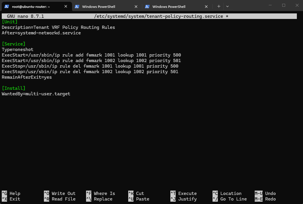
So we create instead a new systemd service:
nano /etc/systemd/system/tenant-policy-routing.service
[Unit]
Description=Tenant VRF Policy Routing Rules
After=systemd-networkd.service

[Service]
Type=oneshot
ExecStart=/usr/sbin/ip rule add fwmark 1001 lookup 1001 priority 500
ExecStart=/usr/sbin/ip rule add fwmark 1002 lookup 1002 priority 501
ExecStop=/usr/sbin/ip rule del fwmark 1001 lookup 1001 priority 500
ExecStop=/usr/sbin/ip rule del fwmark 1002 lookup 1002 priority 501
RemainAfterExit=yes

[Install]
WantedBy=multi-user.target
Then:
systemctl daemon-reload
systemctl enable --now tenant-policy-routing.service

And verify:
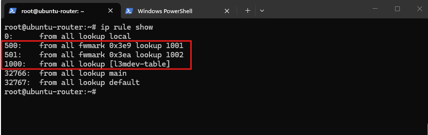
The two policy-routing rules are now active. Packets carrying firewall mark
1001(0x3e9) are routed through Tenant 1 routing table1001, while packets marked with1002(0x3ea) use Tenant 2 routing table1002.The systemd service ensures that these rules are automatically restored after a reboot.
ip rule show
Note: Running
netplan applyrebuilds parts of the Linux routing configuration and may remove policy-routing rules that were created outside Netplan.In this case, restart the
tenant-policy-routing.serviceto restore the tenantfwmarkrules.
After rebooting the Ubuntu router, the systemd service is active and the two fwmark policy-routing rules have been restored automatically.
Together with the persistent Netplan and nftables configuration, both tenant networks can therefore use the shared Internet connection immediately after system startup.
Verifying Simultaneous Tenant Internet Access with Wireshark
To conclude the configuration, we will generate Internet traffic from both tenant VMs simultaneously and capture the packets on the Ubuntu router.
This demonstrates that both tenants can use the same overlapping 192.168.100.0/24 address space while their traffic remains separated by the VRF routing contexts and is forwarded through the shared WAN interface.
For the capture, we should run TShark on both tenant-facing interfaces simultaneously so we get a clean capture of:
- Tenant 1:
192.168.100.20entering througheth3 - Tenant 2:
192.168.100.10entering througheth1 - both pinging
8.8.8.8simultaneously
sudo tshark -i eth1 -i eth3 -f "icmp and host 8.8.8.8" -w tenant-parallel-internet.pcapng
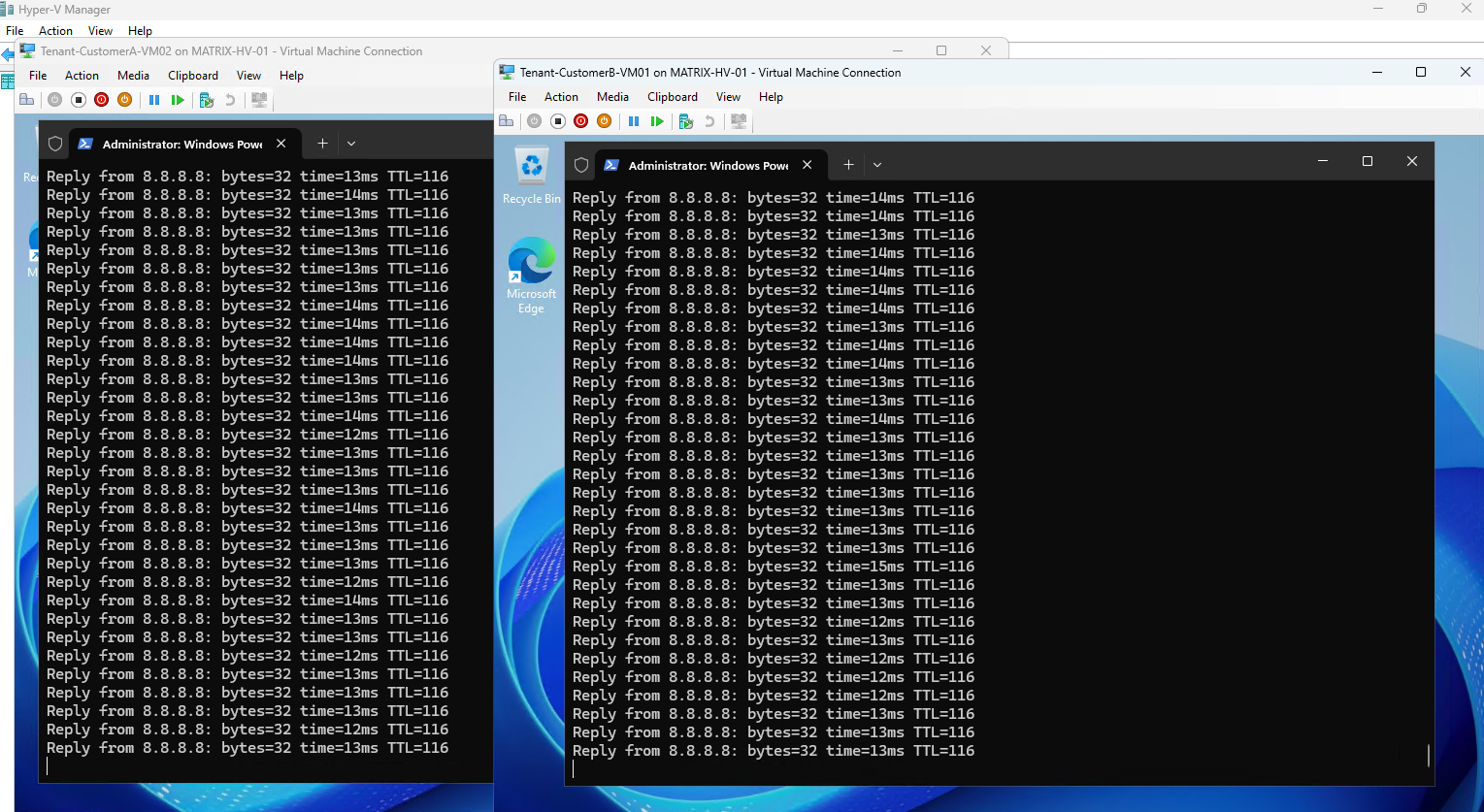
To verify the configuration, I started simultaneous pings to 8.8.8.8 from both tenant VMs, confirming that both tenants can access the Internet through the shared WAN connection.
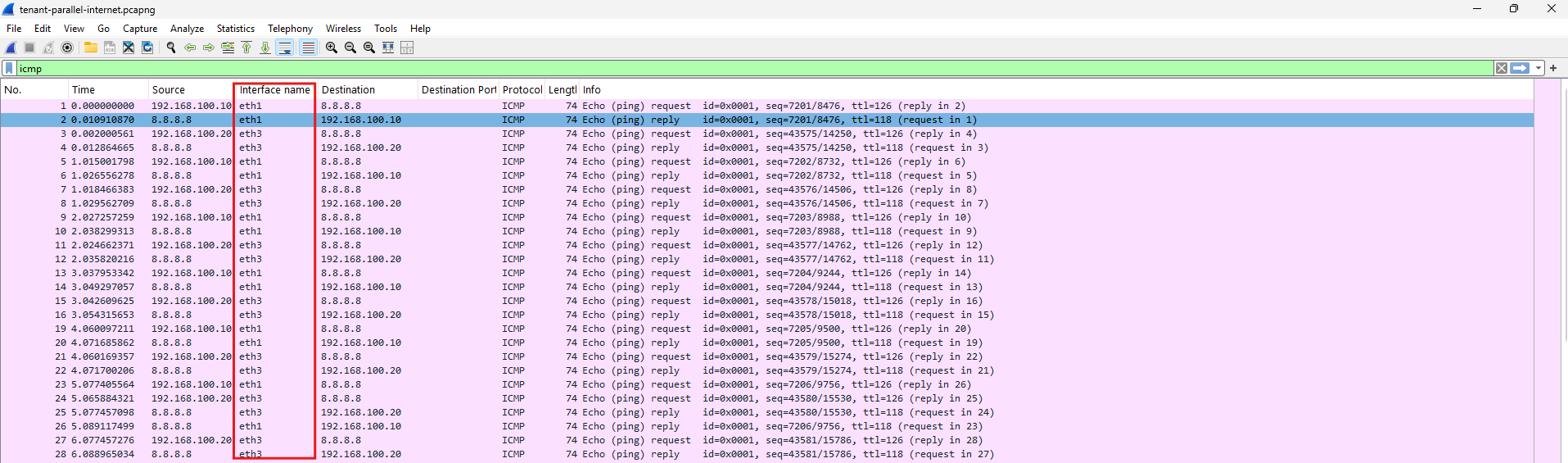
The Wireshark capture shows both tenant flows simultaneously on their respective Ubuntu router interfaces.
Traffic from
192.168.100.10is received and returned througheth1, while traffic from192.168.100.20useseth3.Although both VMs belong to the same overlapping
192.168.100.0/24address space, their traffic remains associated with the correct tenant routing context while both tenants access the same Internet destination8.8.8.8.
Links
Virtual Routing and Forwarding (VRF)
https://docs.kernel.org/networking/vrf.html