Windows Server Software Defined Networking (SDN) and Hyper-V Network Virtualization (HNV) – Part 3: Providing External HNV Connectivity with the Native SDN Gateway and pfSense
In Part 2 of this series, we connected a second tenant VM to our HNV virtual network and verified communication between tenant workloads running on different Hyper-V hosts. By capturing the traffic with Wireshark, we also examined how HNV uses VXLAN encapsulation to transport the tenant Customer Addresses (CAs) across the physical Provider Address (PA) network.
So far, however, our HNV tenant network has remained isolated from networks outside the SDN fabric. In this third part, we will extend our environment and provide external Layer-3 connectivity for the tenant network.
For this purpose, we will deploy the native Microsoft SDN components required for external connectivity, including the Software Load Balancer (SLB) infrastructure and the SDN Gateway. We will then create a Virtual Gateway and an SDN Gateway Connection for our Tenant-CustomerA virtual network.
On the external side, we will use our existing pfSense router. Rather than replacing the Microsoft SDN Gateway, pfSense acts as the upstream router connected to the SDN Gateway through a dedicated Layer-3 transit network. We will also see why simply connecting a pfSense network adapter to the SDN-managed Hyper-V switch is not sufficient, and how the adapter must be properly onboarded into the Network Controller and Virtual Filtering Platform (VFP).
Finally, we will verify complete end-to-end connectivity from an isolated HNV tenant workload through the Microsoft SDN Gateway and pfSense to the external network and the Internet.
In Part 4, we will introduce a second tenant using an overlapping IP address space and demonstrate how HNV keeps both tenant networks isolated despite identical addressing.
This will also expose an important limitation when such overlapping tenant networks are extended to an external router such as pfSense, which uses a single routing domain. We will address this limitation in Part 5 by using Virtual Routing and Forwarding (VRF) to extend the tenant-specific routing domains beyond the Microsoft SDN fabric.
In Part 6, we will extend the overlapping tenant networks even further by connecting each HNV tenant to a separate Azure Virtual Network (VNet) through its own Site-to-Site IPsec VPN, using XFRM interfaces and Linux VRFs to preserve the individual tenant routing contexts. XFRM interfaces were introduced to overcome design limitations of the existing Linux VTI devices and provide a more flexible interface-based approach for IPsec processing.
- External HNV Connectivity Architecture
- Deploying the Software Load Balancer Infrastructure
- Deploying the SDN Gateway Infrastructure
- Verifying the SDN Gateway Network Configuration
- Adding a Gateway Subnet to the HNV Tenant Network
- Adding a Virtual Gateway for the Tenant Network
- Creating the First SDN Gateway Connection
- Verifying End-to-End HNV Connectivity Through the SDN Gateway
- Capturing HNV Tenant WAN Traffic Through the SDN Gateway and pfSense with Wireshark
- Troubleshooting
- Links
External HNV Connectivity Architecture
So far, our HNV tenant workloads can communicate within their isolated virtual network, but they have no connectivity to networks outside the tenant address space. In this section, we will use pfSense as a shared SDN gateway to provide routed connectivity between the HNV tenant network and external networks.
In our lab, pfSense serves as the shared gateway/router for the HNV environment rather than using the native Microsoft SDN Gateway role. This allows us to demonstrate how tenant traffic can leave the virtualized HNV network while keeping the lab architecture relatively simple.
For Tenant-CustomerA, the target is essentially:
Tenant HNV VNet
      │
      │ VXLAN/HNV
      ▼
Microsoft SDN Gateway VM(s)
      │
      ├── Network Controller
      ├── requires SLB infrastructure
      └── BGP / physical network integration
              │
              ▼
        External Router
              │
           Internet
Deploying the Software Load Balancer Infrastructure
Before we can deploy the native Microsoft SDN Gateway, the Software Load Balancer (SLB) infrastructure must be installed first. Windows Server SDN follows a defined deployment order of Network Controller → Software Load Balancer → Gateway, and Windows Admin Center will not allow the Gateway deployment until both prerequisite components are available.
Note: Although the Software Load Balancer (SLB) is a prerequisite for deploying the SDN Gateway through Windows Admin Center, the SLB MUX is not used for workload traffic anywhere in this lab series. It remains part of the deployed SDN infrastructure, while tenant traffic is handled by the SDN Gateway and the external routing components introduced in the subsequent parts.
Internet-bound tenant traffic is forwarded through the SDN Gateway to pfSense, which provides the external routing and NAT functionality.
In Part 5, this design is extended by using an Ubuntu router with separate Linux VRFs, allowing multiple tenants with overlapping IP address spaces to share external connectivity while maintaining isolated routing contexts. In both designs, the SLB MUX is not part of the tenant Internet forwarding path.
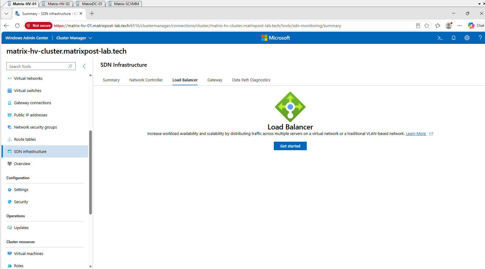
In Windows Admin Center, navigate to SDN infrastructure → Load Balancer. Since no Software Load Balancer has been deployed yet, Windows Admin Center displays the initial deployment page. Click Get started to launch the SDN Load Balancer deployment wizard.
The Software Load Balancer (SLB) in Windows Server SDN is a distributed load-balancing architecture rather than a traditional standalone load-balancer appliance. During deployment, Windows Admin Center creates one or more SLB Multiplexer (MUX) VMs, which act as the front end between the physical network and the SDN fabric and advertise the configured Virtual IP (VIP) networks to upstream routers using BGP.
The actual workload traffic does not pass through the Network Controller. The Network Controller provides the control plane and programs the required policies into the SLB MUX and the Virtual Filtering Platform (VFP) running on the Hyper-V hosts, where the distributed packet processing and forwarding toward the tenant workloads takes place.
A multiplexer (MUX) combines or directs multiple communication channels through a shared path or resource. In Windows Server SDN, the SLB MUX provides a shared front end through which traffic for multiple VIPs and tenant workloads enters the distributed SDN fabric.
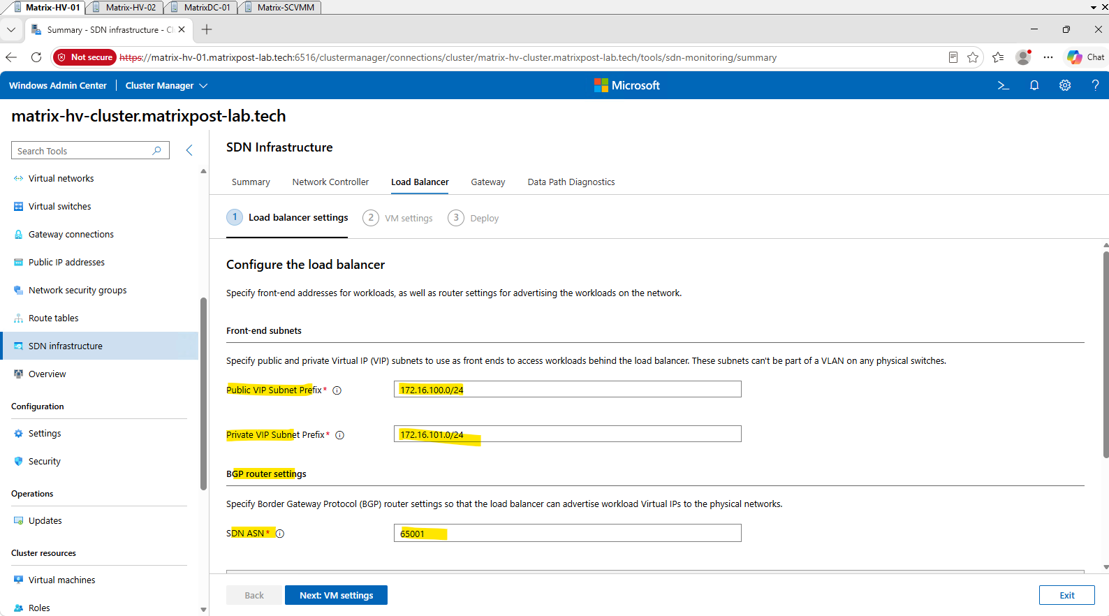
The first step of the deployment wizard configures the Software Load Balancer front-end networks and BGP integration. The Public and Private VIP subnet prefixes provide address pools from which the SLB can allocate Virtual IP addresses (VIPs), while BGP allows the SDN infrastructure to advertise these VIP networks to the external physical network.
For the SLB front-end networks, we configure 172.16.100.0/24 as the Public VIP subnet and 172.16.101.0/24 as the Private VIP subnet.
We also assign the Windows SDN infrastructure the private BGP ASN 65001, which will be used to exchange routing information with our upstream router (pfSense).
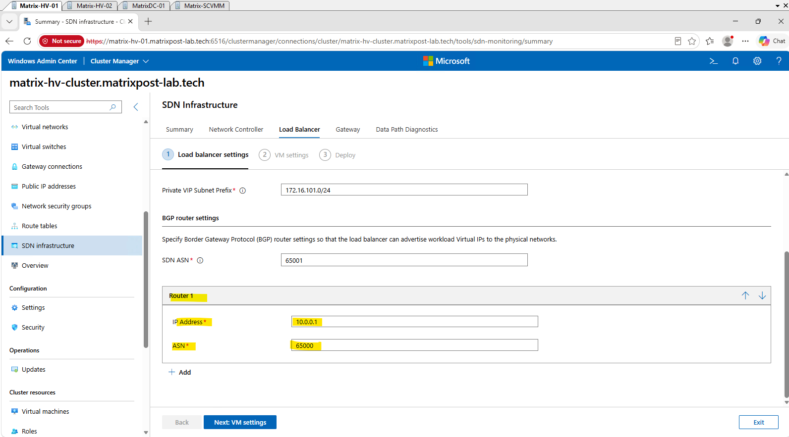
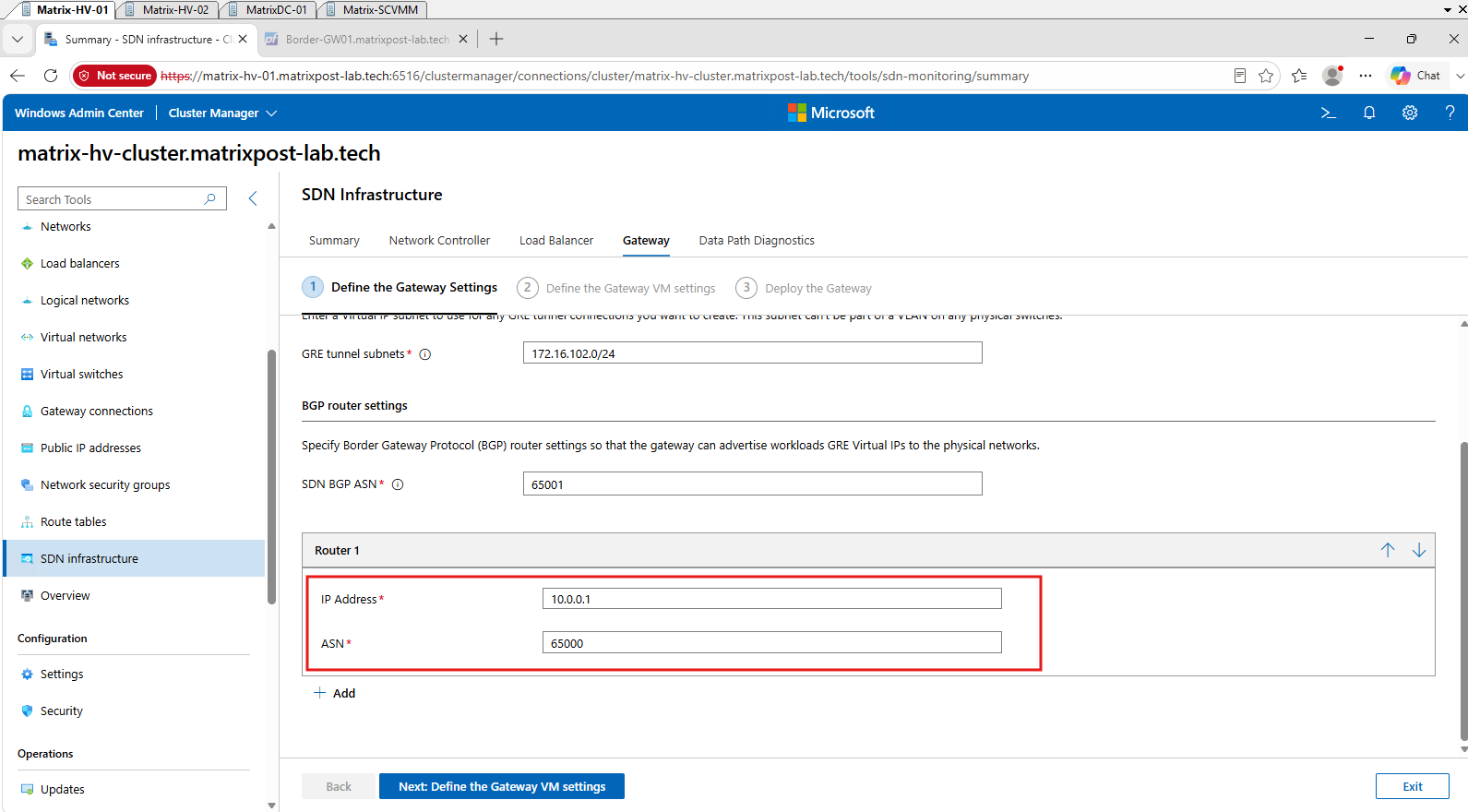
For the BGP router configuration, we use our pfSense LAN interface 10.0.0.1 as the upstream BGP peer and assign pfSense the private ASN 65000.
The Windows SDN infrastructure using ASN 65001 can then advertise its VIP networks to pfSense through BGP.
For the BGP integration, our pfSense router uses FRRouting (FRR), which provides the BGP routing functionality required to peer with the Windows SDN infrastructure.
For details on installing FRR and configuring BGP neighbors, prefix lists, and routing policies in pfSense, see my previous article.
Next click Next: VM settings above.
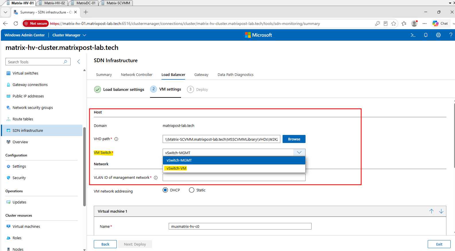
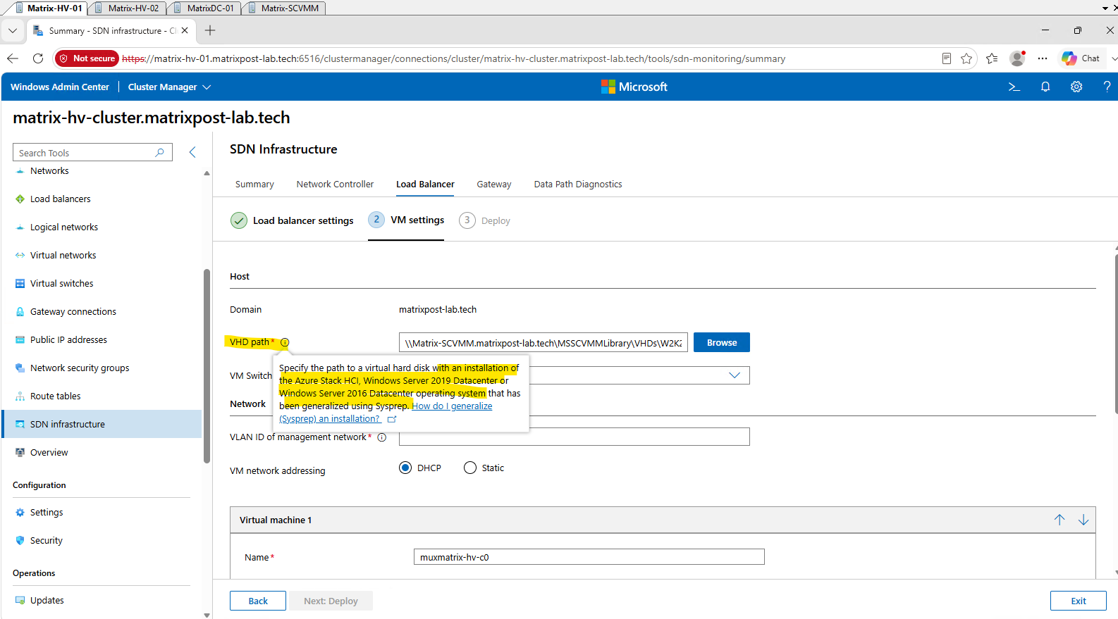
In the Host section, we specify the Windows Server VHDX that Windows Admin Center will use as the source image for deploying the MUX VM. We also select the Hyper-V virtual switch that provides connectivity to the MUX VM management network.
For the VM Switch, we select
vSwitch-VMinstead ofvSwitch-MGMT. Its physical uplinks are connected to a trunk, allowing the MUX VM to use both the Management network on VLAN 10 and the HNV Provider Address network on VLAN 30.Note: The Microsoft SDN deployment architecture assumes a converged Hyper-V virtual switch for the SDN infrastructure. This can also be seen in Microsoft’s SDNExpress configuration, which defines a single global
SwitchNamewhile separating the Management and HNV Provider Address networks throughManagementVLANIDandPAVLANID. The SDNExpress code then applies the Management VLAN through VFP network-adapter isolation, while the MUX HNVPA adapter uses the configured PA VLAN.In our lab, however, the physical network was designed differently.
vSwitch-MGMTis connected to a physical access port in VLAN 10, whilevSwitch-VMis connected to a physical 802.1Q trunk carrying VLAN 30 for the HNV Provider Address network. Windows Admin Center, like SDNExpress, provides only a single VM switch for the MUX deployment and therefore initially connects both MUX adapters to that switch.Further down in this section, we will see how this affects the MUX network adapters during deployment and how we adapted the configuration to our existing physical network design.
Note: We initially attempted the SLB MUX deployment using a generalized Windows Server 2025
StandardVHDX, but the deployment failed during the Virtual machine creation stage.After converting the template to Windows Server 2025 Datacenter and creating a new generalized VHDX, the deployment proceeded successfully, confirming the Datacenter requirement indicated by the Windows Admin Center wizard.
Need to convert Windows Server Standard to Datacenter on the fly without reinstalling the operating system? Check out my following article.
And for creating the generalized Windows Server VM template with SCVMM that we use here, check out my following article.
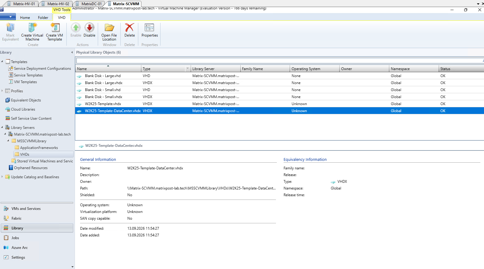
Since Windows Admin Center requires a VHDX rather than an SCVMM VM template, we first determine the virtual disk used by our existing W2K25-DataCenter template.
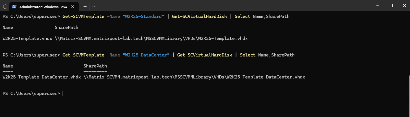
Run the following command on the SCVMM server to determine the path to the generalized
W2K25-Template.vhdx, which we can then reference directly from the SCVMM Library as the source disk for the SLB MUX deployment.
Get-SCVMTemplate -Name "W2K25-DataCenter" | Get-SCVirtualHardDisk | Select Name,SharePath
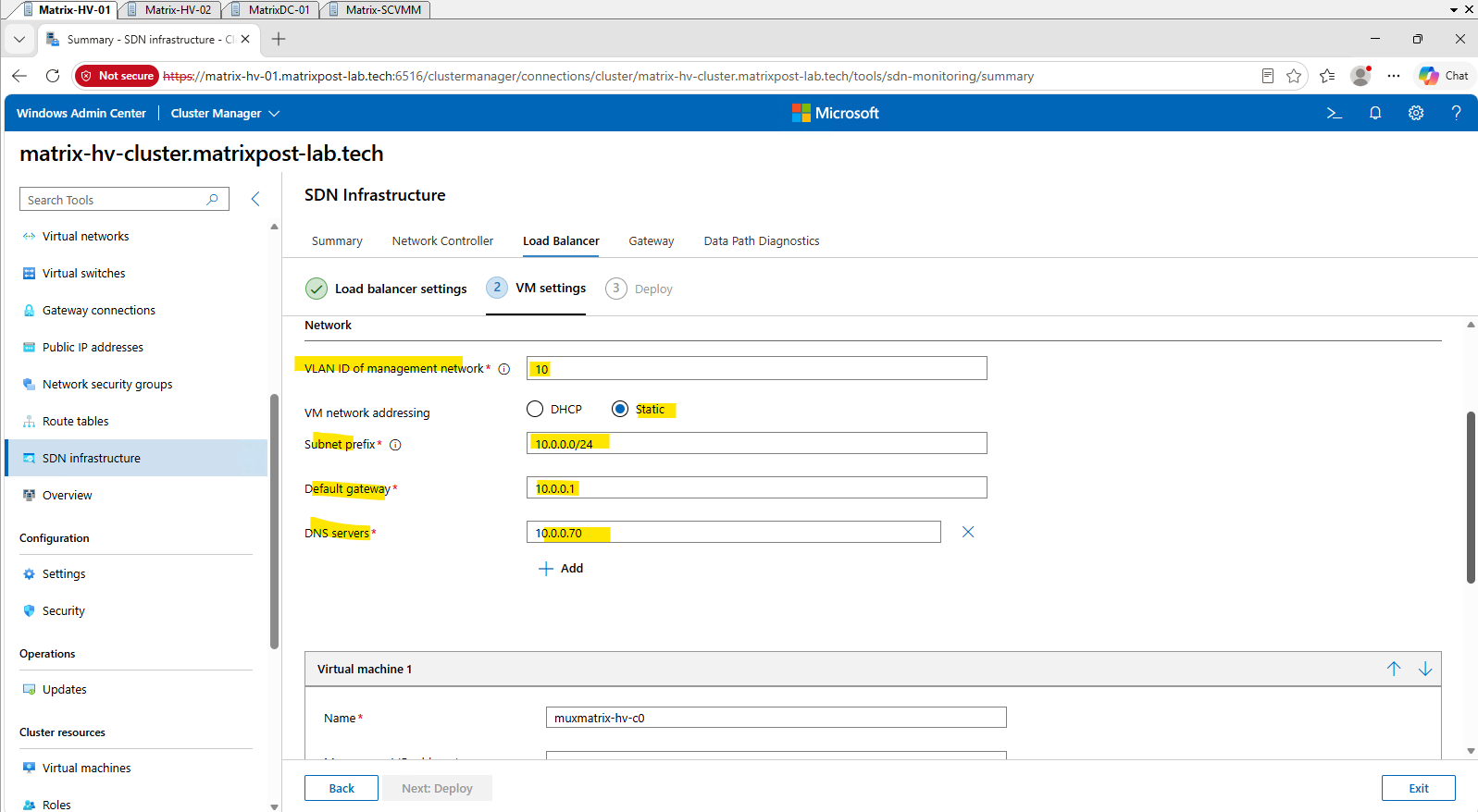
For the MUX VM management network, we use our existing VLAN 10 (10.0.0.0/24), configure 10.0.0.1 as the default gateway, and use our domain controller 10.0.0.70 for DNS resolution.
Although we configure VLAN ID 10 here, we will see further down that Windows Admin Center does not apply this setting to the MUX Management adapter in our deployment. We will therefore adapt the Management adapter configuration after the VM has been created.
For the first SLB MUX VM, we configure 10.0.0.90 as its static management address and 10.0.30.50 as its Provider Address (PA) on the HNV underlay.
The Provider Address is deliberately placed outside the existing dynamic PA pool (
10.0.30.10–10.0.30.49) to avoid address conflicts.
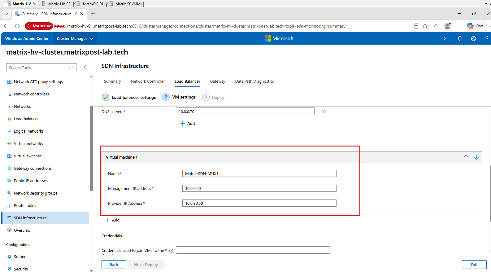
Finally, we provide a domain account with permissions to join the MUX VM to Active Directory, define its local Administrator password, and place the VM files on our Cluster Shared Volume (CSV) under C:\ClusterStorage\Volume1\Matrix-SDN-MUX1.
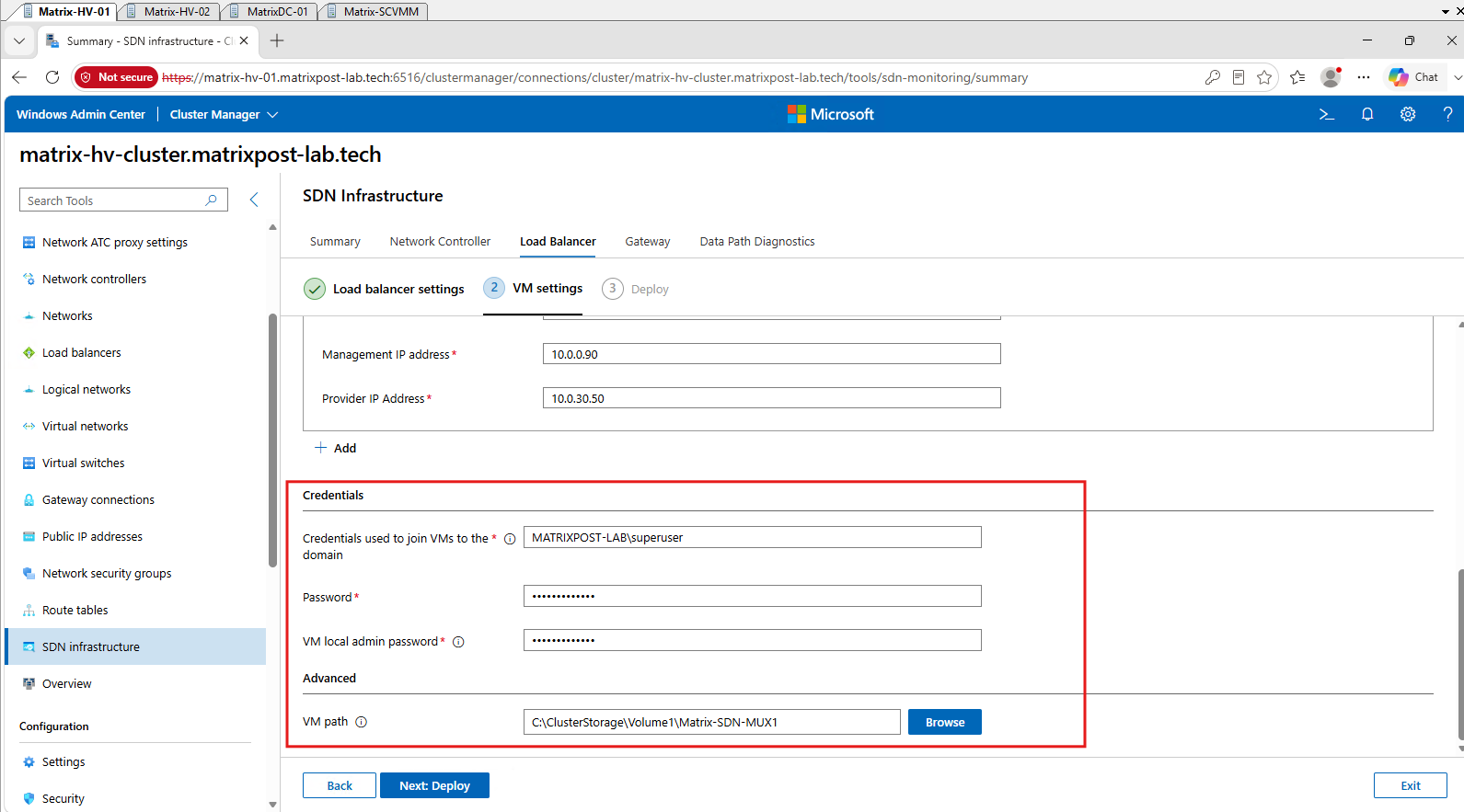
Next click Next: Deploy above.
When the deployment starts, Windows Admin Center prompts for administrative credentials required for the PowerShell double-hop connection to the Hyper-V host. Enter an account with the required administrative permissions and click Continue.
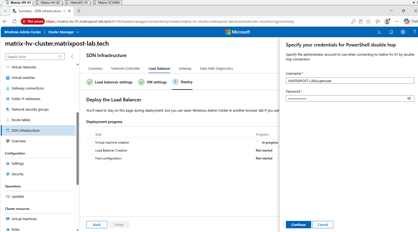
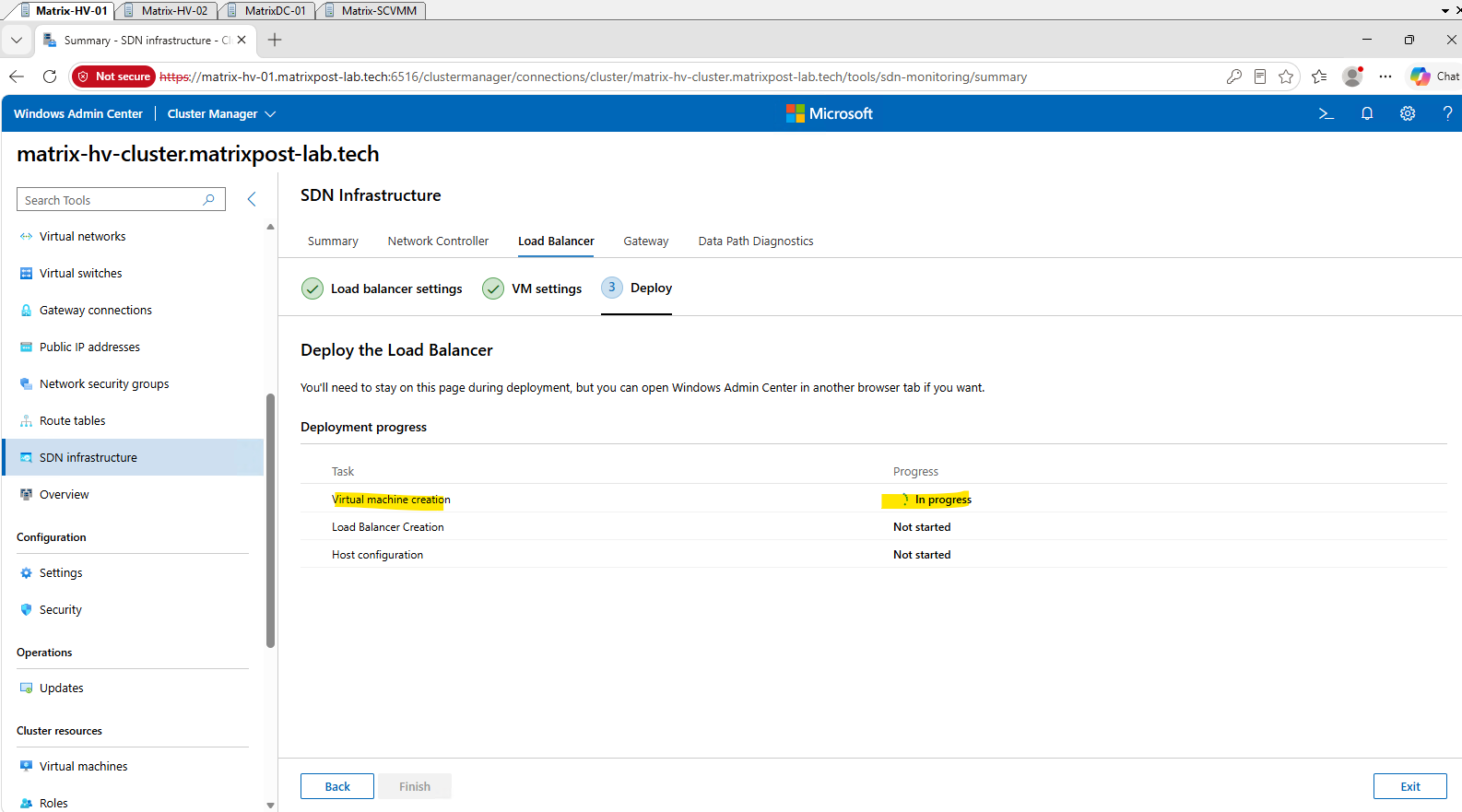
Windows Admin Center now starts the SLB deployment, first creating and configuring the MUX virtual machine, followed by the Load Balancer and the required Hyper-V host configuration. The deployment progress for each stage can be monitored directly in the wizard.
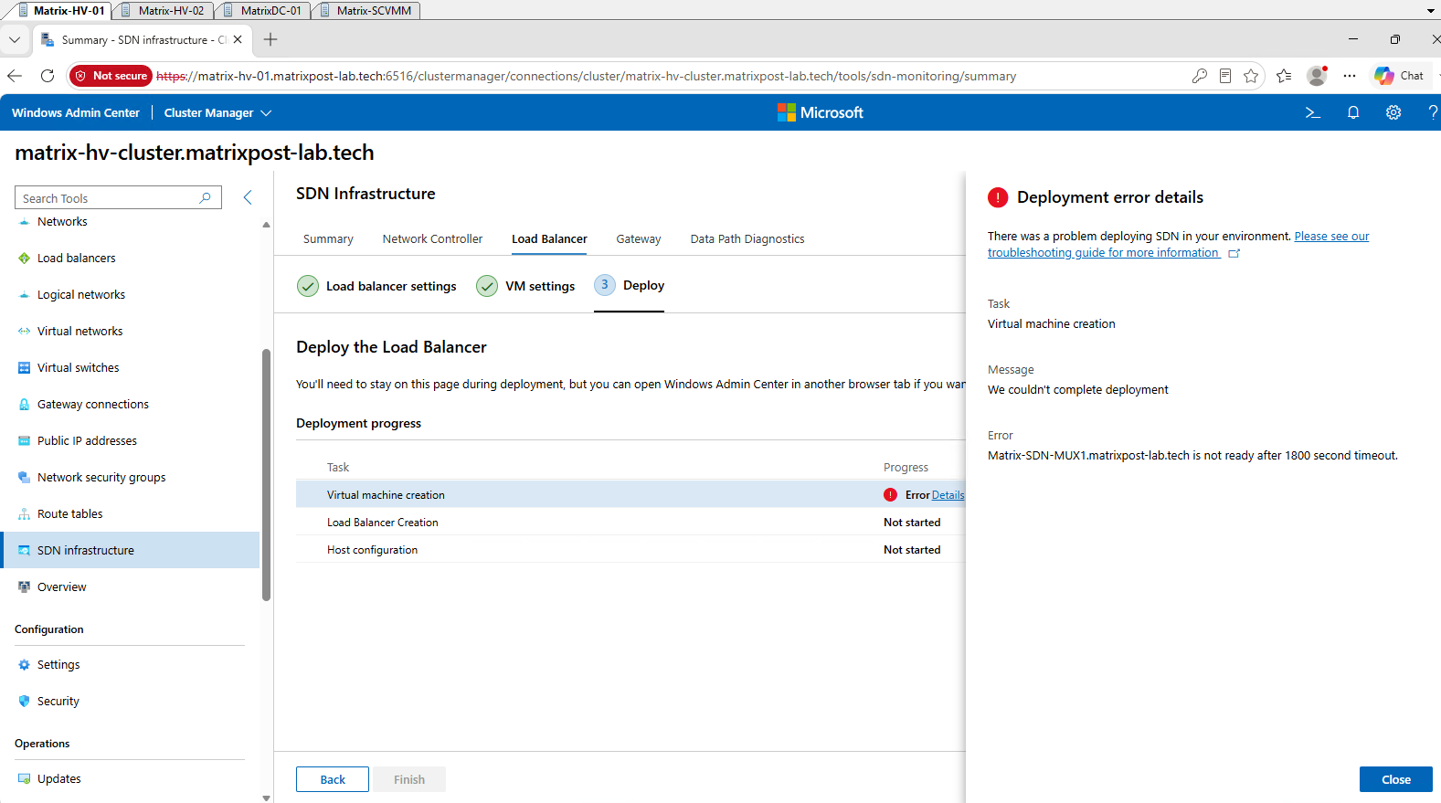
Note: Microsoft states that deploying the complete Software Load Balancer (SLB) infrastructure can typically take 30–60 minutes, depending on the underlying hardware. During this process, Windows Admin Center creates and prepares the MUX VM, copies the generalized VHDX, configures networking, and waits for the guest operating system to become ready before continuing with the Load Balancer and host configuration stages.
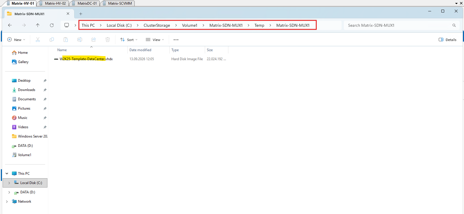
During deployment, Windows Admin Center copies the source
W2K25-Template-Data-Center.vhdxfrom the SCVMM Library share into a temporary directory within the configured Cluster Shared Volume (CSV) before creating the SLB MUX VM.
As mentioned earlier, our Hyper-V hosts use dedicated virtual switches for Management and VM traffic, whereas the Microsoft SDN deployment workflow used by Windows Admin Center and SDNExpress assumes a single converged SDN vSwitch with the individual networks separated by VLANs.
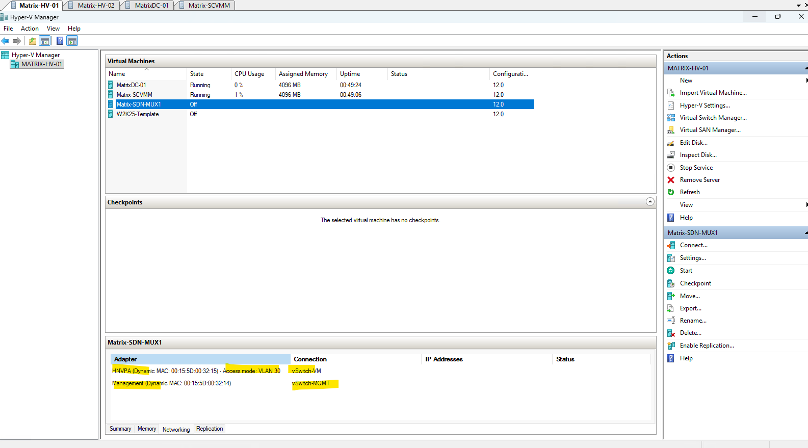
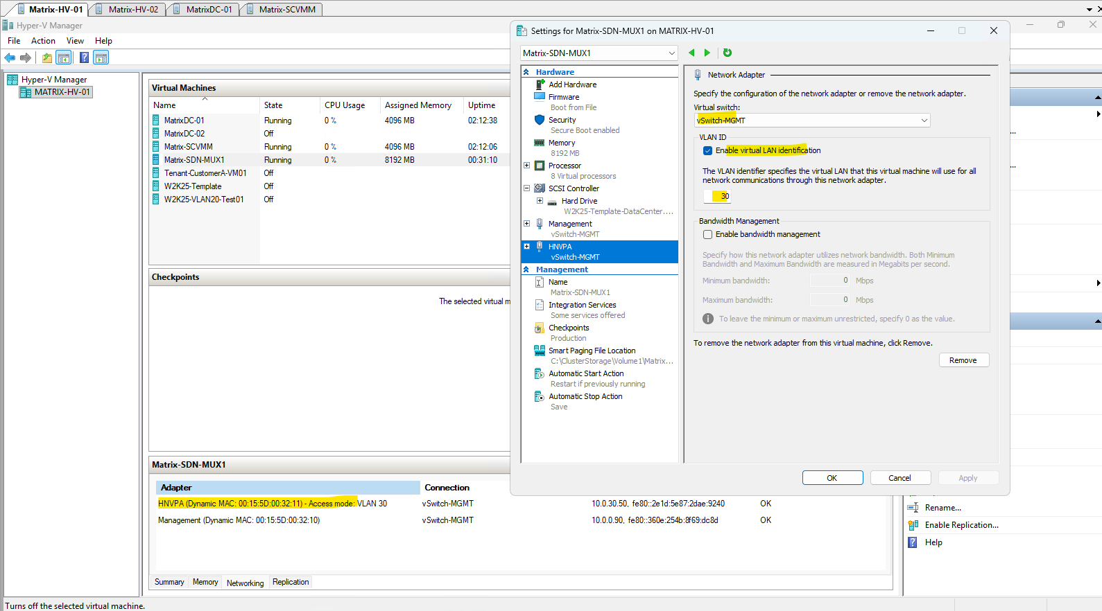
After Windows Admin Center created the MUX VM, both virtual network adapters were initially connected to
vSwitch-VM. The HNVPA adapter was correctly configured for VLAN 30, but the configured Management VLAN 10 was not applied to the Management adapter.Because
vSwitch-VMis connected to a physical 802.1Q trunk, the untagged Management adapter could not reach our VLAN 10 management network. We therefore manually changed the Management adapter tovSwitch-MGMT, whose physical uplink is connected to an access port in VLAN 10. No VLAN configuration is required on the Management adapter itself in this configuration.The resulting MUX connectivity is therefore HNVPA →
vSwitch-VM→ VLAN 30 → physical trunk, while Management →vSwitch-MGMT→ untagged → physical access VLAN 10. After this change, Windows Admin Center was able to continue provisioning the MUX VM successfully.
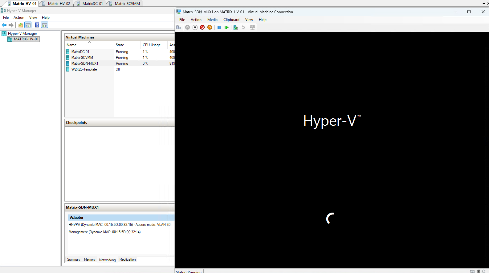
After creating the MUX VM shell and configuring its virtual network adapters, Windows Admin Center continues preparing the VM in the background. A few minutes later, the VM is automatically started and the generalized Windows Server image begins its initial setup and specialization process.
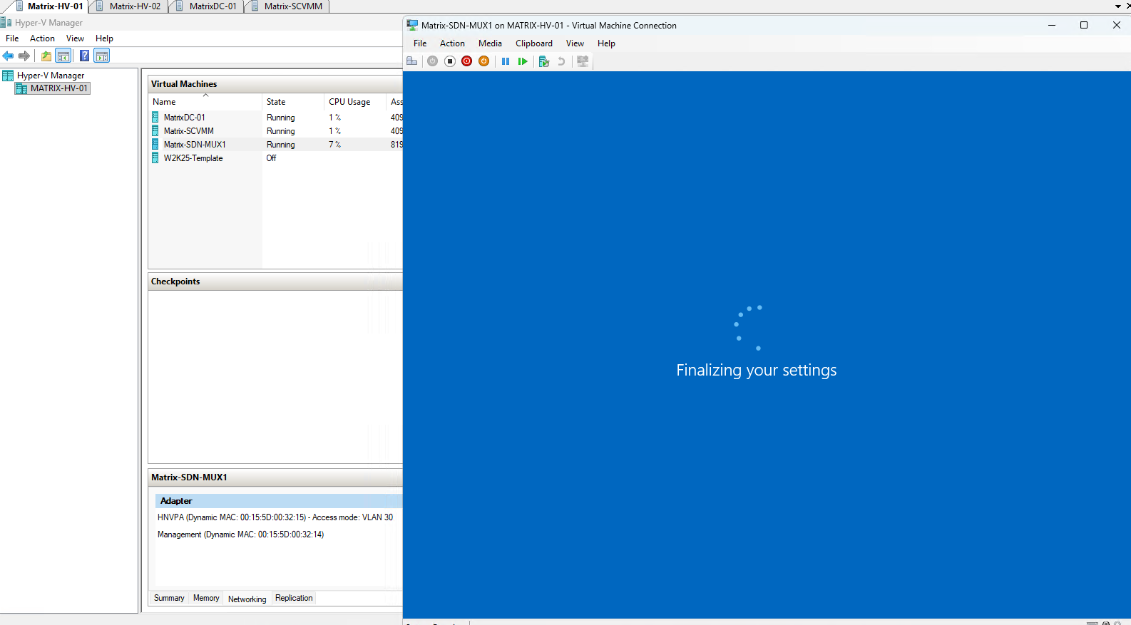
During the automated provisioning process, the MUX VM is restarted several times while Windows and the required SDN components are configured. After roughly the third boot in our deployment, Windows displayed “Finalizing your settings”, indicating that the guest configuration was nearing completion.
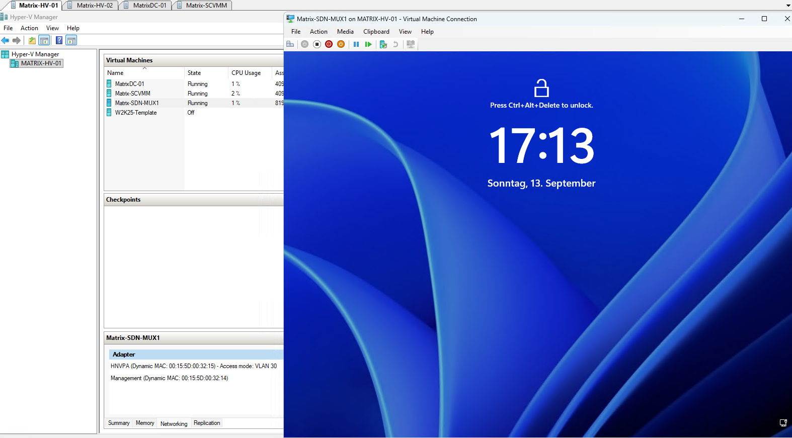
After the automated provisioning and several restarts have completed, the MUX VM reaches the Windows Server lock screen, confirming that the operating system deployment has finished. Windows Admin Center can now continue with the remaining SLB configuration and host integration tasks.
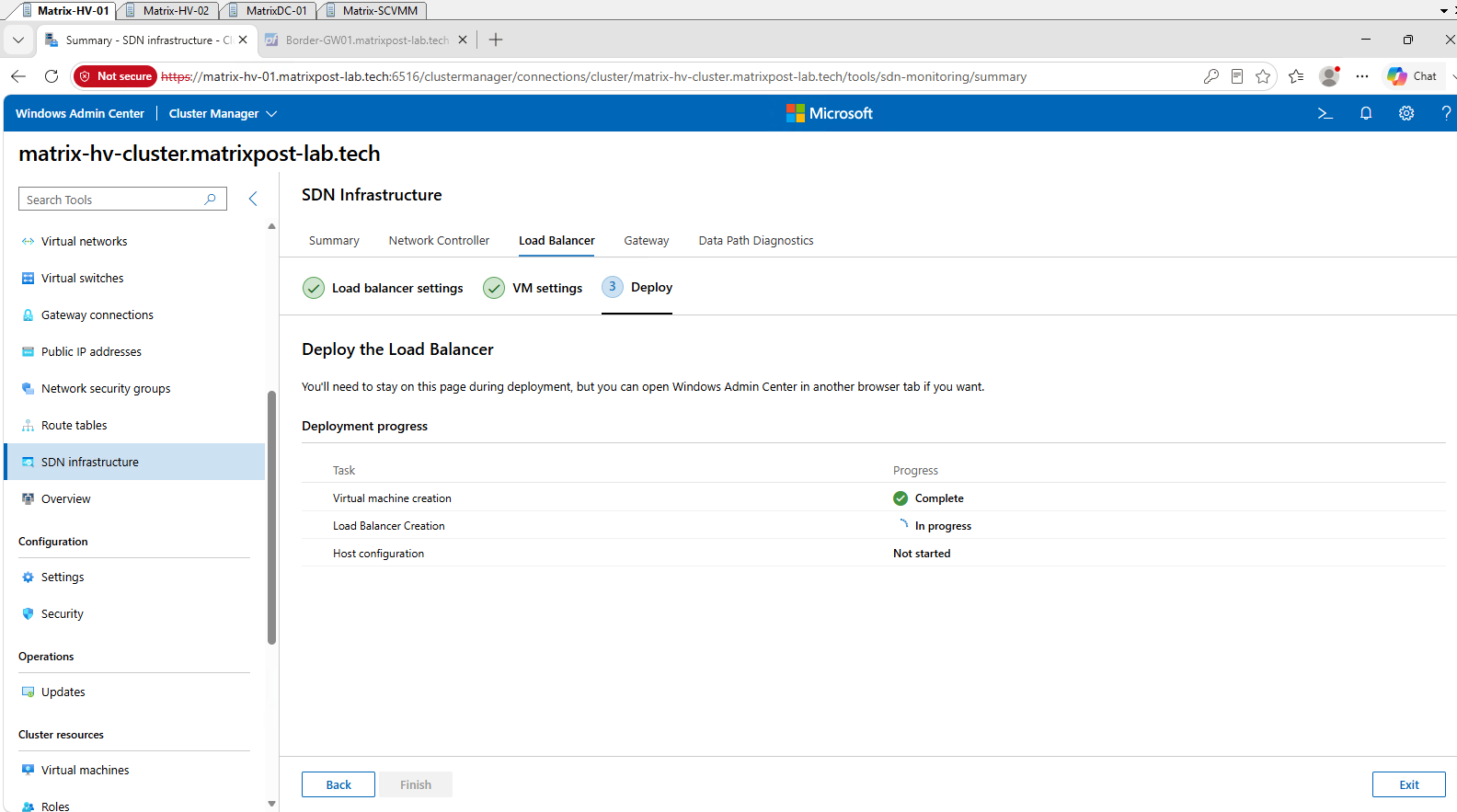
Once the MUX VM operating system provisioning is complete, Windows Admin Center marks Virtual machine creation as Complete and automatically proceeds with Load Balancer Creation. Afterward, it configures the Hyper-V hosts to integrate them with the newly deployed SLB infrastructure.
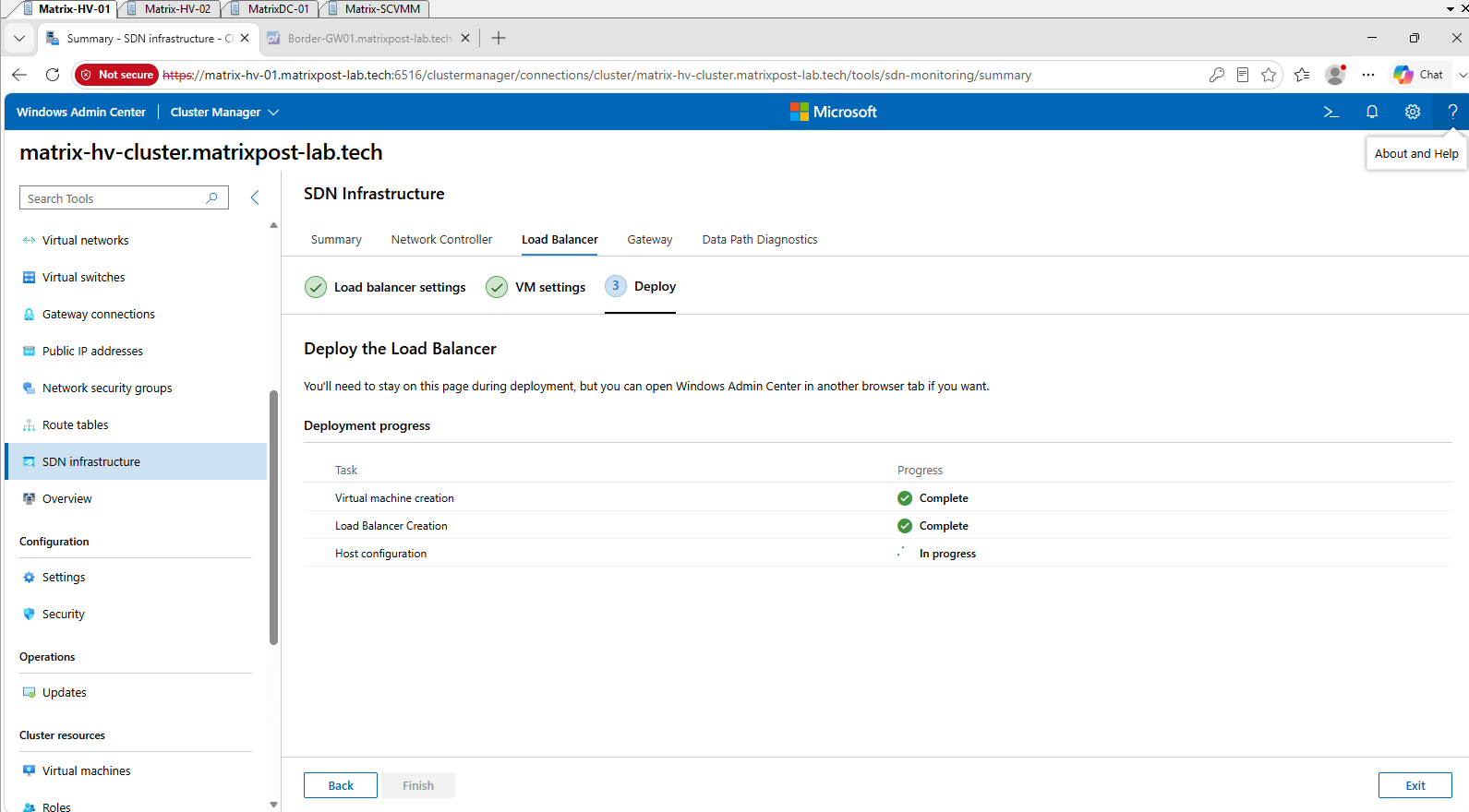
After the Load Balancer Creation stage completes, Windows Admin Center proceeds with Host configuration. During this stage, the Hyper-V hosts are integrated with the SLB infrastructure and configured for the distributed SDN data path.
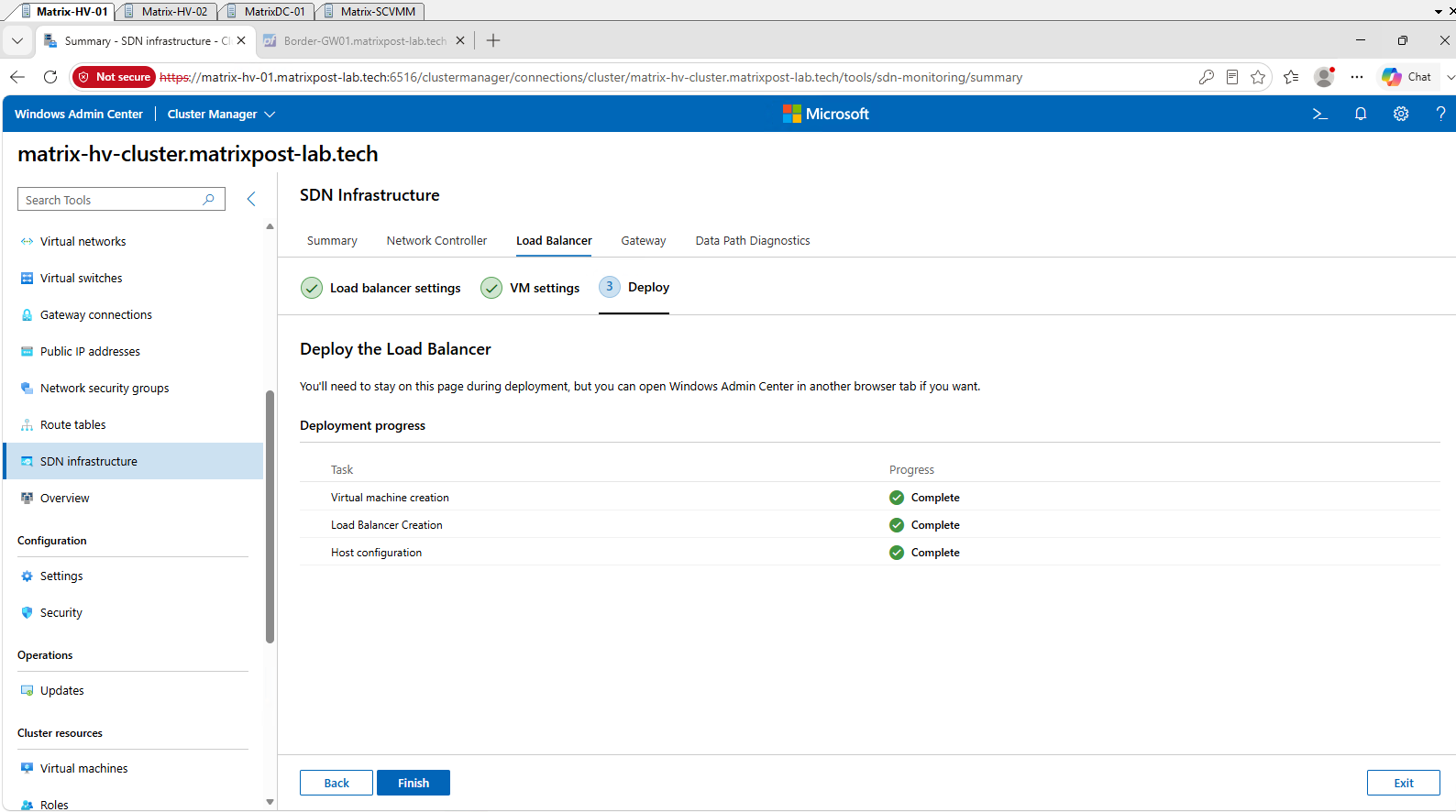
Finally, Windows Admin Center reports all three deployment stages, Virtual machine creation, Load Balancer Creation, and Host configuration, as Complete. This confirms that the SLB infrastructure has been successfully deployed and we can finish the wizard.
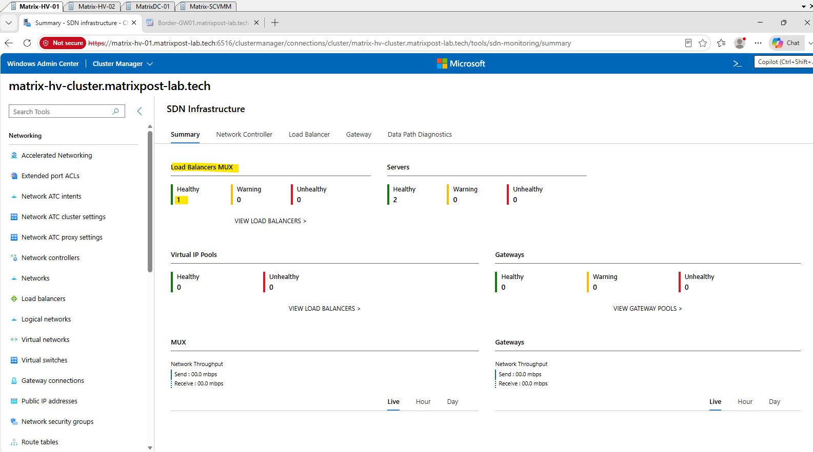
After completing the deployment, the SDN Infrastructure Summary reports the SLB MUX as Healthy and both Hyper-V servers as Healthy, with no warnings or unhealthy components. This confirms that the MUX and the distributed SLB components on both Hyper-V hosts are successfully integrated with the SDN infrastructure.
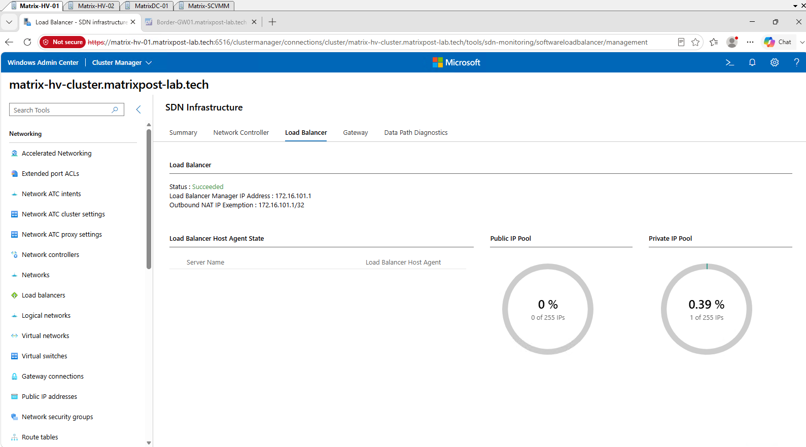
The Load Balancer view confirms a successful deployment and shows the automatically assigned Load Balancer Manager IP 172.16.101.1. Because this address is allocated from our Private VIP subnet (172.16.101.0/24), the Private IP Pool already shows one consumed address, while the Public VIP pool (172.16.100.0/24) remains unused.
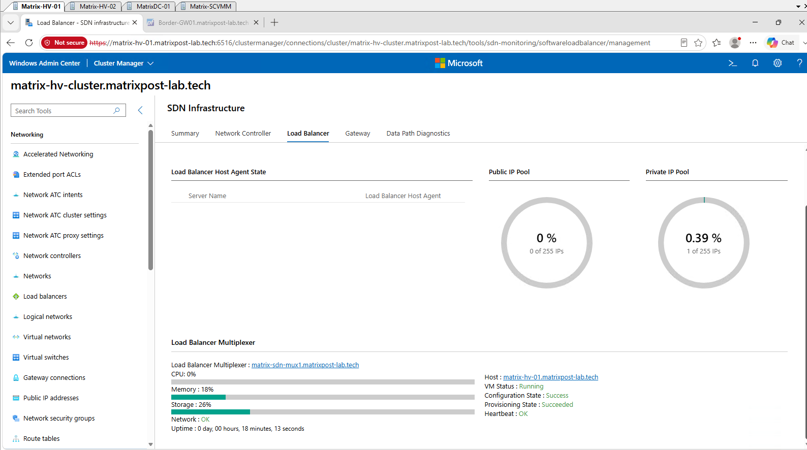
Further down, Windows Admin Center provides detailed health information for the deployed Load Balancer Multiplexer matrix-sdn-mux1.matrixpost-lab.tech. The MUX is Running, with Configuration State: Success, Provisioning State: Succeeded, Heartbeat: OK, and Network: OK, confirming that it is fully operational and registered with the SDN infrastructure.
With the Software Load Balancer infrastructure successfully deployed and validated, we can now proceed to the next component of the Windows Server SDN architecture. In the following section, we will deploy the SDN Gateway to provide connectivity between our isolated HNV tenant networks and external networks.
Deploying the SDN Gateway Infrastructure
The SDN Gateway provides connectivity between the isolated HNV tenant networks and networks outside the SDN fabric. In our lab, it will ultimately provide the path between our Tenant-CustomerA virtual network and the external network through pfSense, which acts as our upstream router and BGP peer.
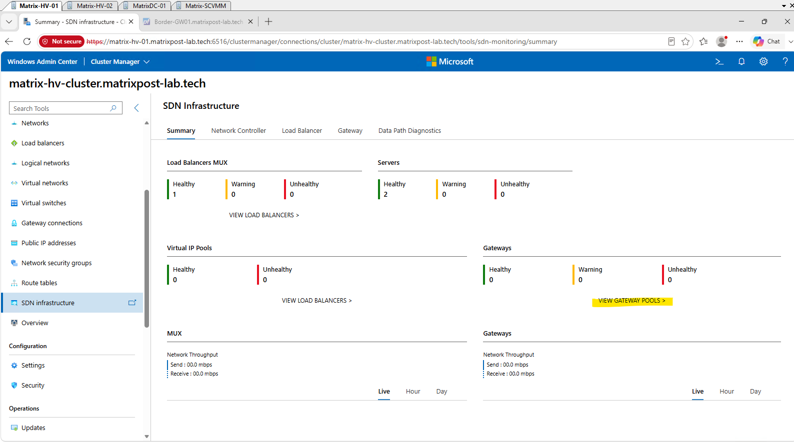
Open SDN Infrastructure → VIEW GATEWAY POOLS → Get started in Windows Admin Center to begin the deployment.
For the GRE tunnel infrastructure, we reserve the unused virtual subnet 172.16.102.0/24, while keeping the existing SDN BGP ASN 65001 used by our SDN fabric.
Although we do not initially use GRE for our tenant connectivity, the SDN Gateway supports GRE-based connections to external networks, and we will take a closer look at this feature at the end of this article.
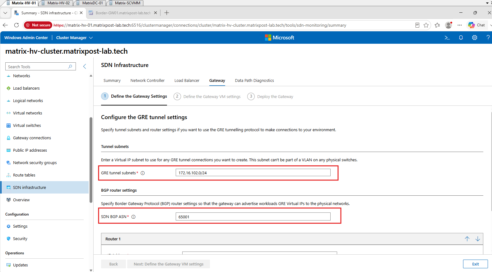
The SDN Gateway uses ASN 65001, while pfSense is the upstream BGP router using ASN 65000. So we can proceed with Next: Define the Gateway VM settings.
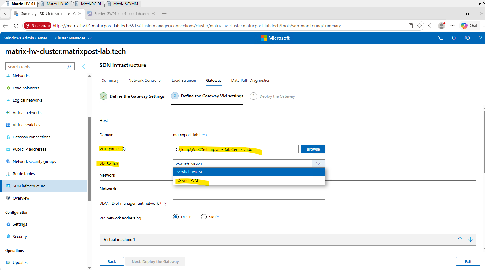
For the Gateway VM deployment, we again select vSwitch-VM as required by the converged SDN deployment workflow and will later adapt the Management adapter to our dedicated vSwitch-MGMT.
This time, we first copied our generalized Windows Server 2025 Datacenter VHDX to the Hyper-V host and use the local path
C:\Temp\W2K25-Template-DataCenter.vhdxto significantly speed up the deployment.
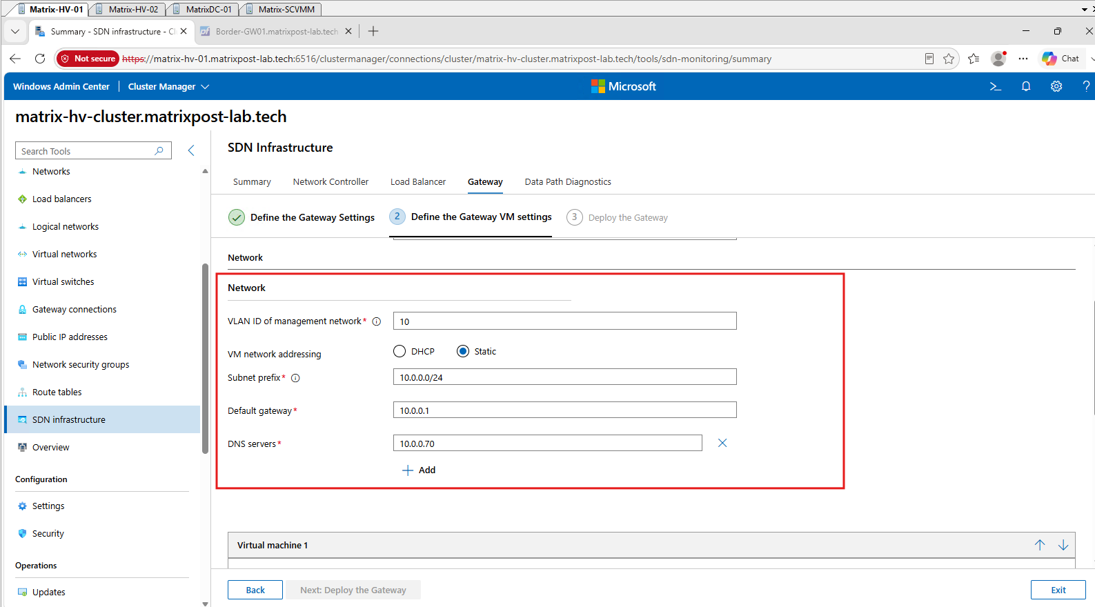
For the Gateway VM management network, we again configure VLAN 10 (10.0.0.0/24) with our pfSense router 10.0.0.1 as the default gateway and domain controller 10.0.0.70 as the DNS server.
As with the MUX, we will adapt the Management adapter to our dedicated
vSwitch-MGMTafter WAC creates the VM.
For our lab, we deploy a single Gateway VM named Matrix-SDN-GW1 with the static management address 10.0.0.95 and therefore leave Redundant Gateways set to 0. We also provide our domain credentials for automatically joining and configuring the Gateway VM in matrixpost-lab.tech.
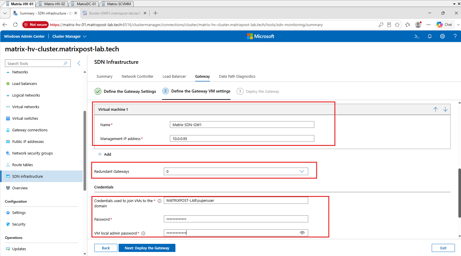
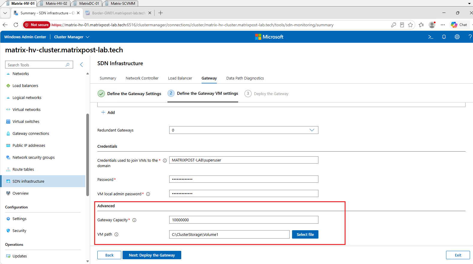
For the Gateway Capacity, we keep the default value of 10000000, which defines the capacity available to the Gateway for tenant connections. The Gateway VM itself is stored on our cluster shared storage under C:\ClusterStorage\Volume1.
Next: Deploy the Gateway
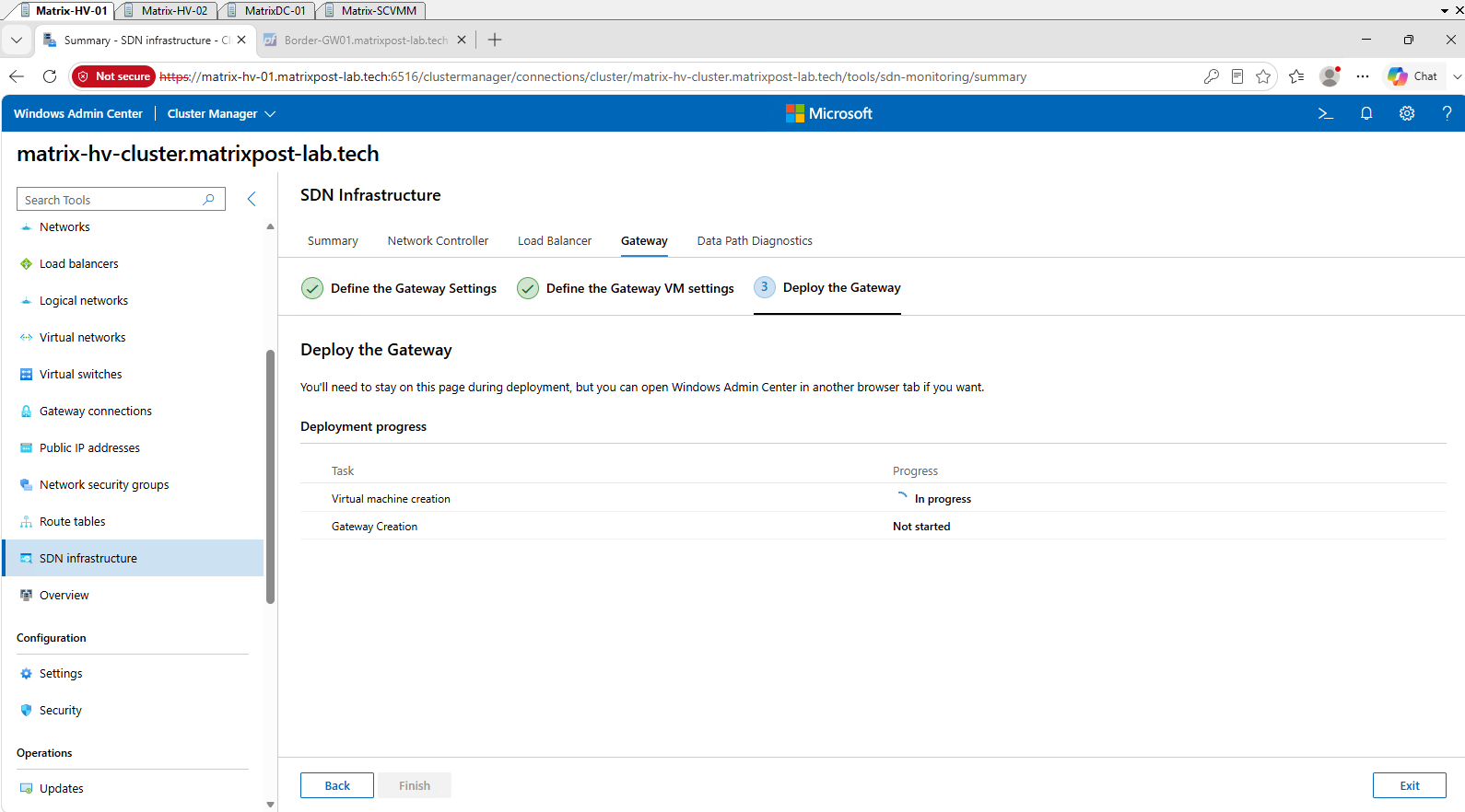
The Gateway deployment now begins with Virtual machine creation, while the actual Gateway Creation stage remains pending. Windows Admin Center will first deploy and prepare Matrix-SDN-GW1 before configuring it as part of the SDN Gateway infrastructure.
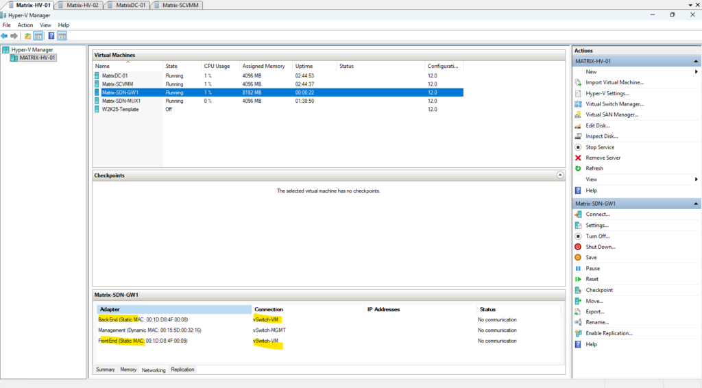
After Windows Admin Center creates the initial Gateway VM shell, all three adapters are connected to the selected vSwitch-VM according to Microsoft’s converged SDN switch model.
Because our lab uses a dedicated management switch, we manually move only the Management adapter to
vSwitch-MGMT, while the FrontEnd and BackEnd adapters remain connected tovSwitch-VMfor SDN data-plane connectivity.
After creating the SDN Gateway VM shell and configuring its virtual network adapters, Windows Admin Center continues preparing the VM in the background. A few minutes later, the VM is automatically started and the generalized Windows Server image begins its initial setup and specialization process.
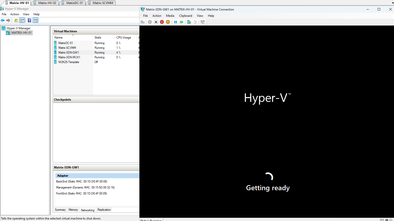
During the automated provisioning process, the SDN Gateway VM is restarted several times while Windows and the required SDN components are configured. After roughly the third boot in our deployment, Windows displayed “Finalizing your settings”, indicating that the guest configuration was nearing completion.
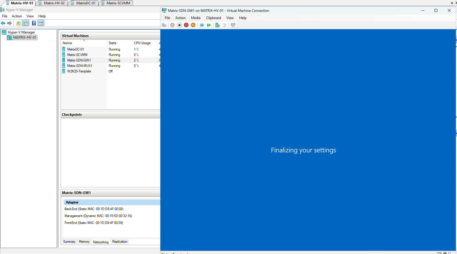
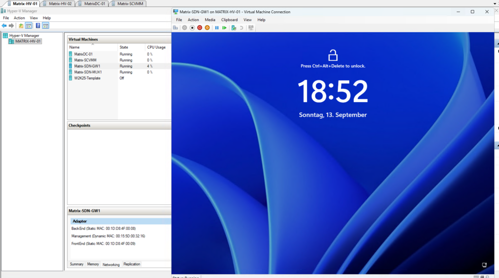
After the automated provisioning and several restarts have completed, the SDN Gateway VM reaches the Windows Server lock screen, confirming that the operating system deployment has finished. Windows Admin Center can now continue with the remaining Gateway creation tasks.
After the Gateway VM creation completes, Windows Admin Center automatically proceeds with the Gateway Creation stage. During this step, the VM is configured and integrated with the Network Controller and the Windows Server SDN infrastructure.
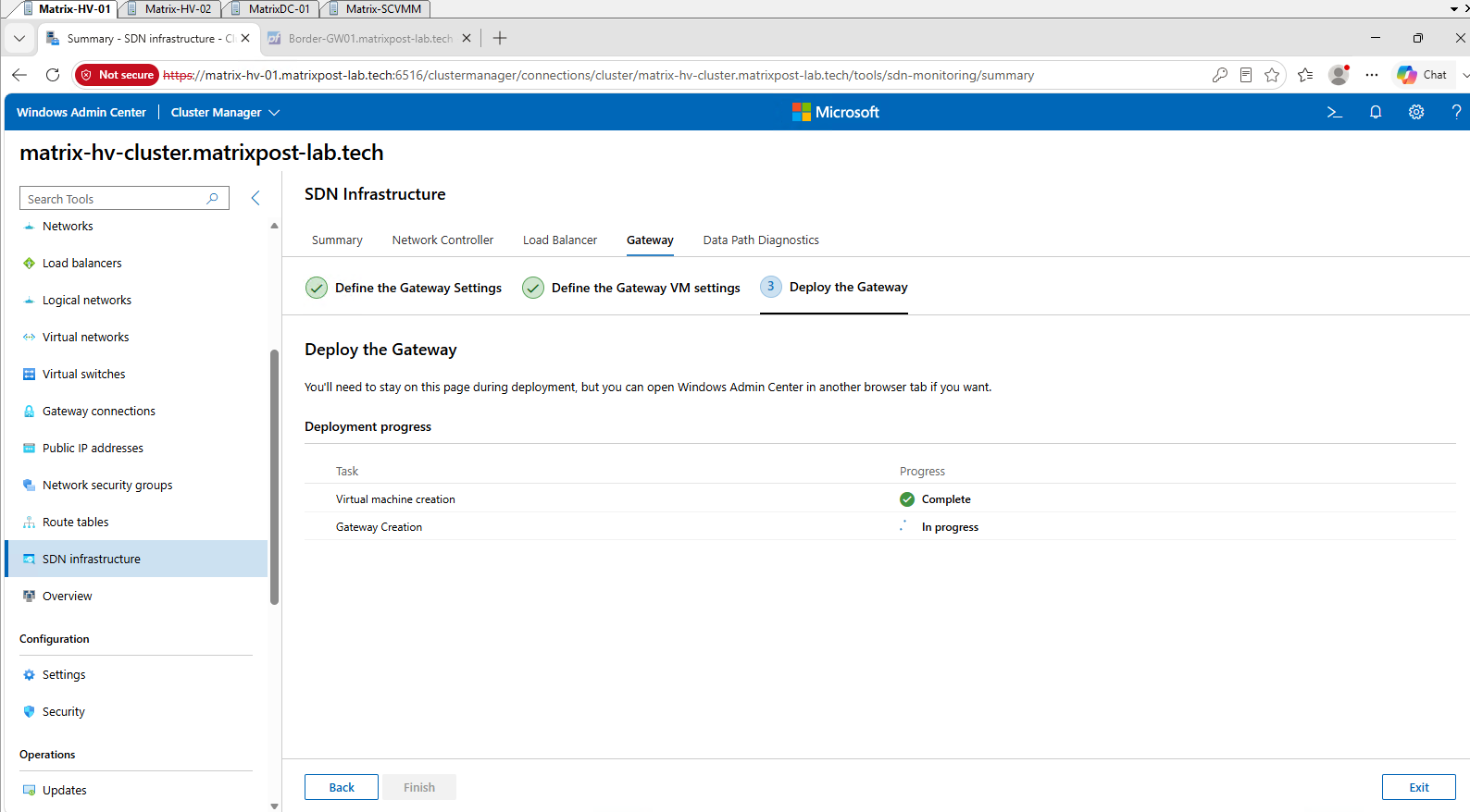
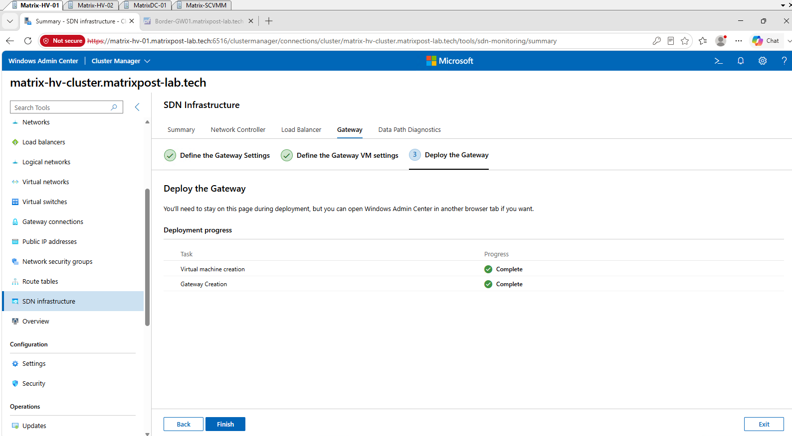
Finally, both Virtual machine creation and Gateway Creation are reported as Complete, confirming that the SDN Gateway has been successfully deployed and integrated with our SDN infrastructure. We can now finish the deployment wizard.
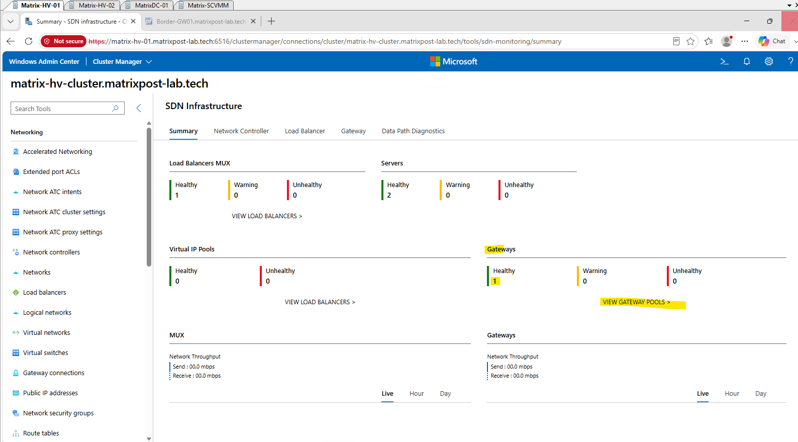
Back in the SDN Infrastructure Summary, the newly deployed SDN Gateway is now reported as Healthy, with no warnings or unhealthy components. This confirms that the Gateway has been successfully registered with the Network Controller and is operational within our SDN infrastructure.
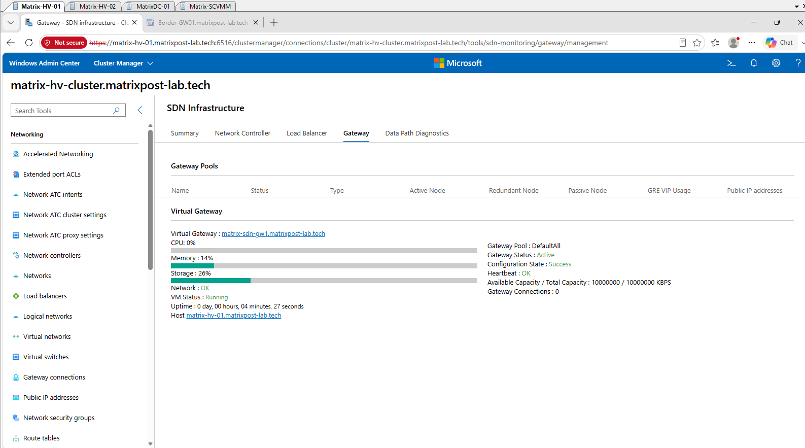
The Gateway view provides detailed health information for matrix-sdn-gw1.matrixpost-lab.tech.
The Gateway is Active and Running, with Configuration State: Success, Heartbeat: OK, and Network: OK, confirming that the Gateway VM is fully operational; currently, no Gateway Connections have been configured.
Verifying the SDN Gateway Network Configuration
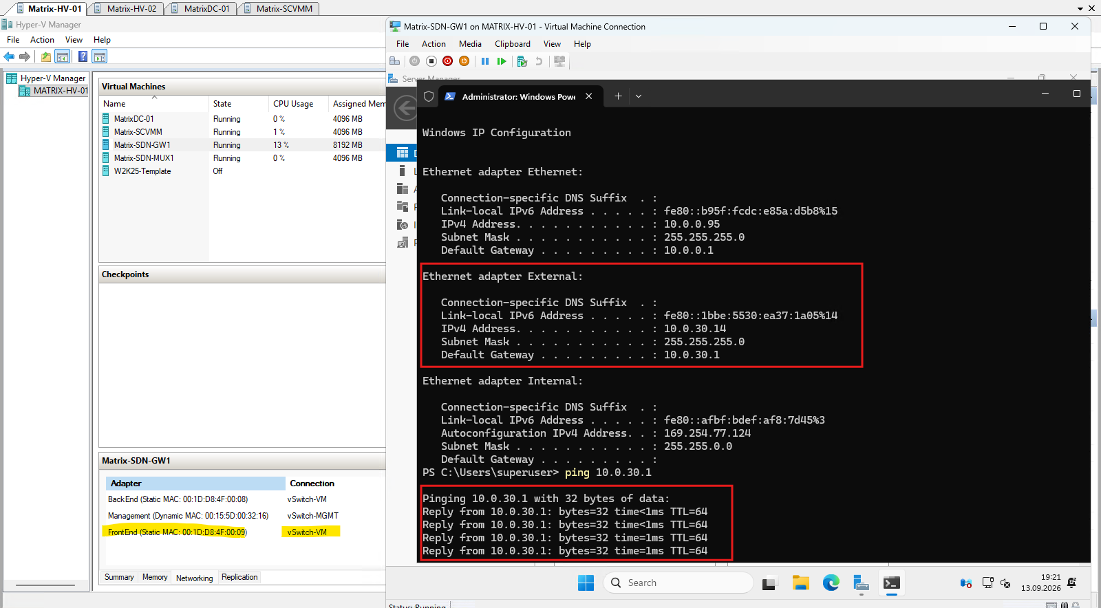
Before configuring our first Gateway Connection, we verify the network configuration automatically assigned to the Gateway VM. This allows us to confirm the connectivity of its Management, FrontEnd, and BackEnd interfaces and how they are integrated into the SDN fabric.
The FrontEnd adapter of the SDN Gateway is connected to vSwitch-VM and has automatically received the Provider Address 10.0.30.14/24 with 10.0.30.1 as its gateway.
The BackEnd/Internal adapter shows an APIPA address (169.254.x.x), which is expected because it is not used as a conventional IP-routed interface with a statically assigned provider address. Instead, it represents the internal SDN/HNV-facing side of the Gateway, with tenant connectivity handled through the SDN data plane and VFP policies.
Although Hyper-V does not show a conventional VLAN 30 assignment on this adapter, the successful ping to
10.0.30.1confirms that the SDN-controlled FrontEnd interface is correctly communicating with our HNV Provider Address network on VLAN 30.Note: this works because the adapter is controlled by the Network Controller, which programs the required network policies into the Virtual Filtering Platform (VFP) on the Hyper-V virtual switch, allowing the traffic to be associated with the Provider network without manually configuring VLAN 30 through the standard Hyper-V VLAN settings.
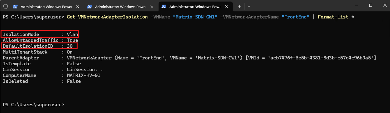
The reason the Gateway FrontEnd can communicate on VLAN 30 without a conventional Hyper-V VLAN assignment becomes visible with Get-VMNetworkAdapterIsolation.
Network Controller has configured the adapter with
IsolationMode: VlanandDefaultIsolationID: 30, whileMultiTenantStackis enabled for SDN processing. The VLAN association is therefore enforced through the SDN isolation policy rather than the standardGet-VMNetworkAdapterVlanconfiguration.
Get-VMNetworkAdapterIsolation -VMName "Matrix-SDN-GW1" -VMNetworkAdapterName "FrontEnd" | Format-List *
In Hyper-V, VLAN assignment is generally enforced on the virtual switch port, not inside the guest operating system.
For example, a conventional VLAN can be configured with
Set-VMNetworkAdapterVlan -VMName "VM01" -Access -VlanId 30
while SDN/HNV can use the more advanced VM network adapter isolation policy, as seen on our Gateway FrontEnd with DefaultIsolationID 30 and MultiTenantStack.
Adding a Gateway Subnet to the HNV Tenant Network
Before we can create a Gateway Connection for Tenant-CustomerA, the virtual network requires a dedicated Gateway Subnet. This subnet provides the internal connection point between the tenant virtual network and the SDN Gateway and is separate from the tenant workload subnet 192.168.100.0/24.
IThe Gateway Subnet is a dedicated subnet within the tenant virtual network used for communication between the SDN Gateway and the virtual network.
When a Gateway Connection later is created, IP addresses from this subnet are provisioned on the Gateway VM, providing its tenant-facing connectivity; Microsoft notes that this subnet can therefore be relatively small, for example
/30,/29, or/28.Source: https://learn.microsoft.com/en-us/azure/azure-local/manage/gateway-connections
To create the required Gateway Subnet, open Virtual networks and select our existing Tenant-CustomerA virtual network.
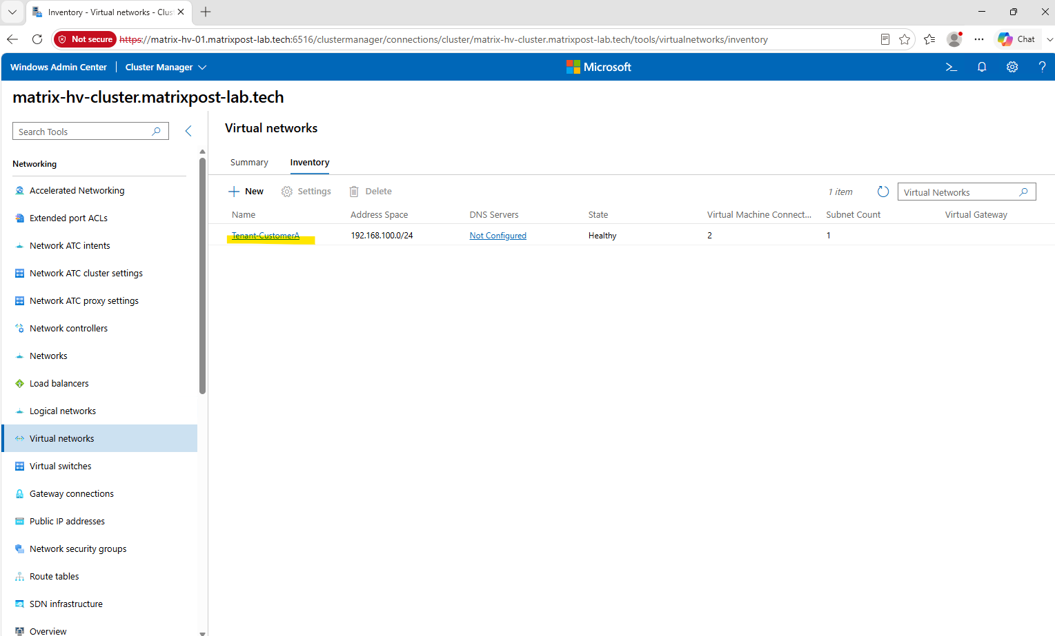
Within Tenant-CustomerA, the existing workload subnet Tenant-CustomerA-Subnet already occupies the current 192.168.100.0/24 address space.
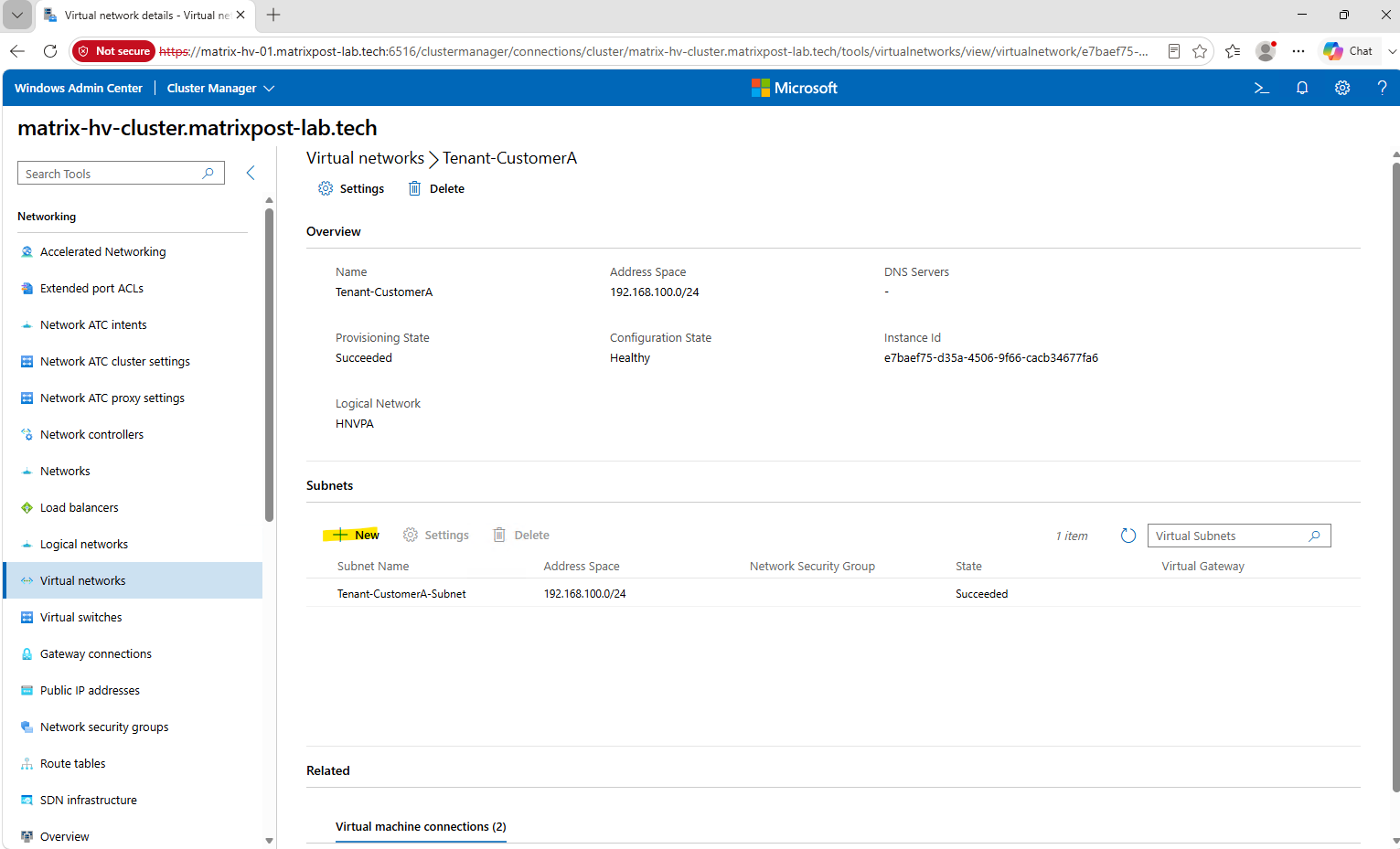
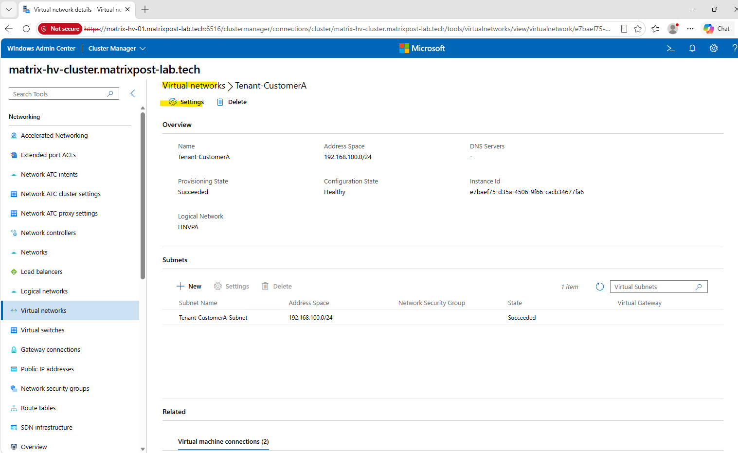
Because the existing 192.168.100.0/24 address prefix is completely occupied by our workload subnet, we expand the Tenant-CustomerA virtual network address space to 192.168.0.0/16. This allows us to add a separate Gateway Subnet while keeping the existing workload subnet unchanged.
Click on Virtual networks Settings.
Extend the virtual network address space to 192.168.0.0/16 and click on Submit.
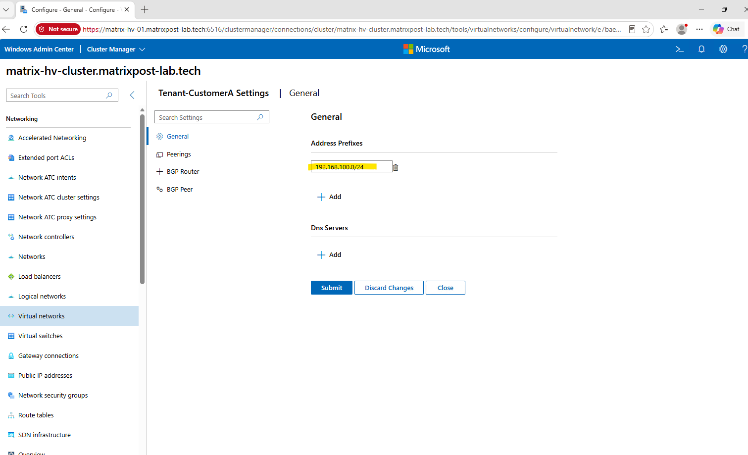
The Tenant-CustomerA has been successfully updated to the broader 192.168.0.0/16 address space, while the existing workload subnet remains unchanged.
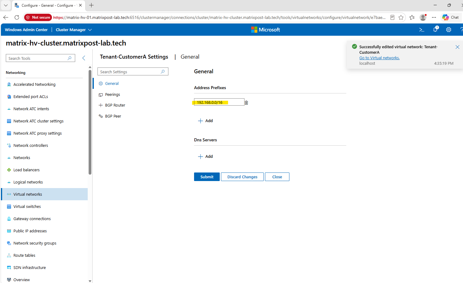
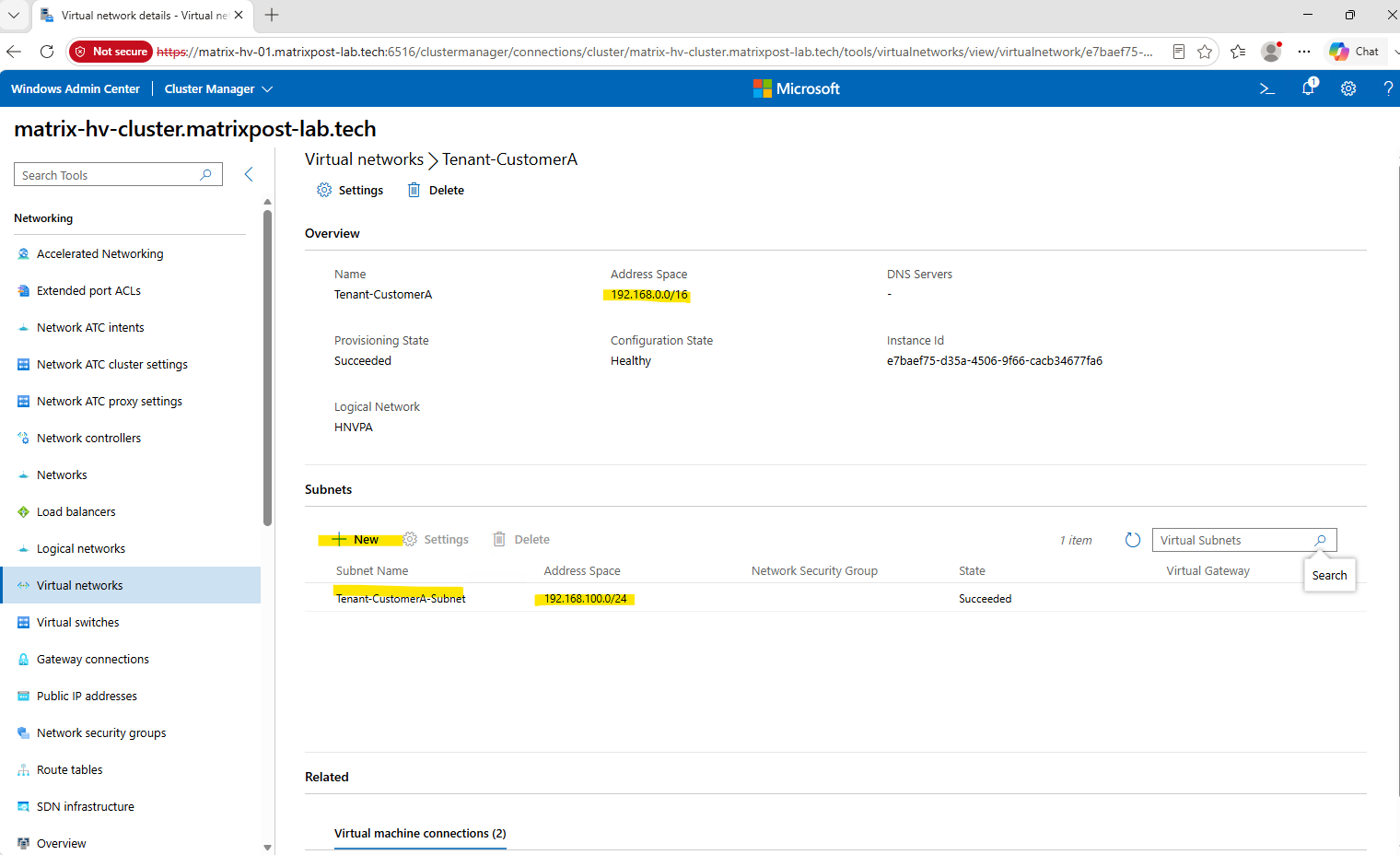
The expanded 192.168.0.0/16 address space is now active while our existing workload subnet remains 192.168.100.0/24.
We can therefore click New under Subnets to create the dedicated Gateway Subnet from the remaining address space.
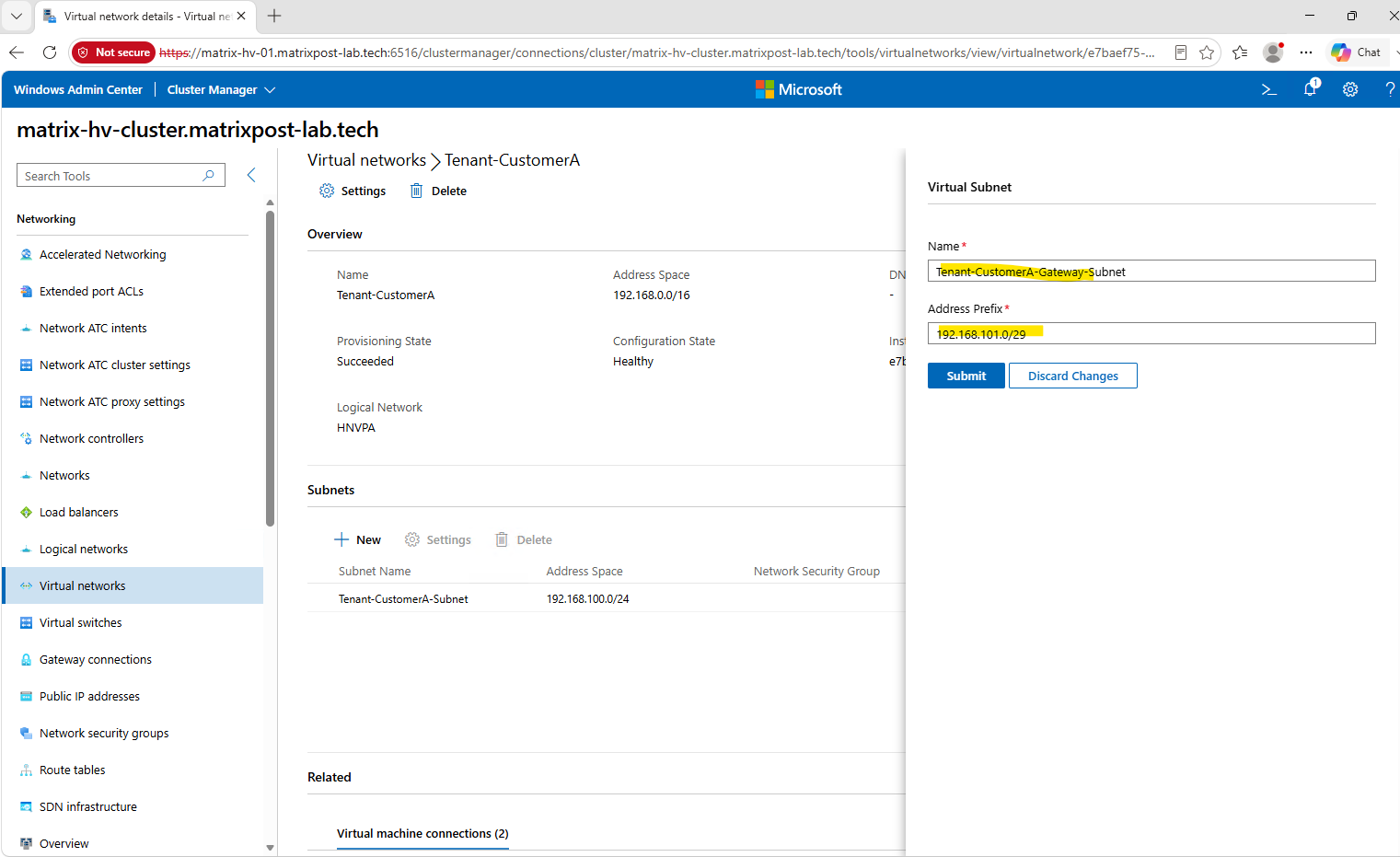
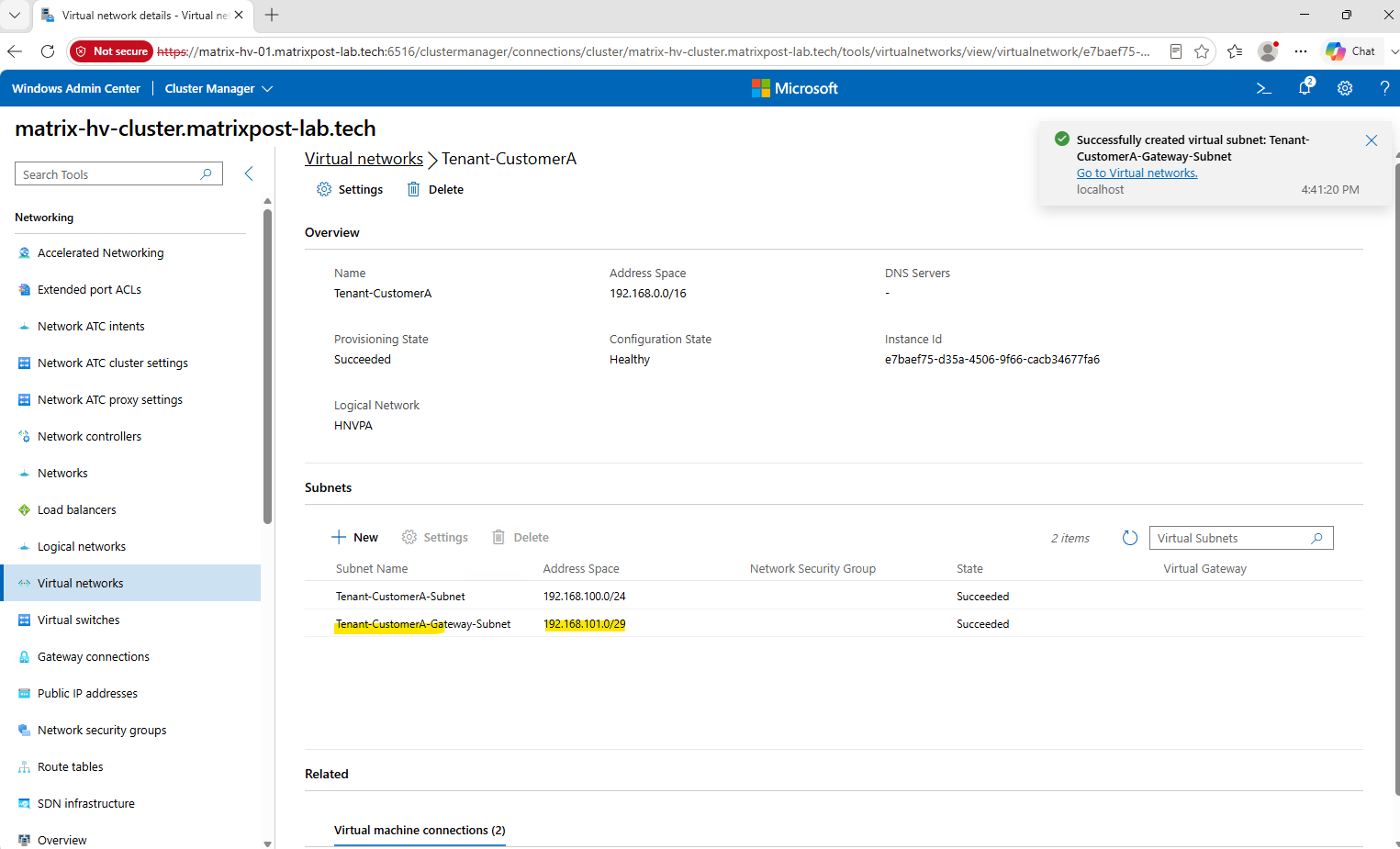
We create the dedicated Tenant-CustomerA-Gateway-Subnet using 192.168.101.0/29, providing a small, separate address range for the SDN Gateway’s tenant-facing connectivity.
Unlike Azure, where the gateway subnet must use the reserved name
GatewaySubnet, Windows Server SDN does not require a specific subnet name. We can therefore use the descriptiveTenant-CustomerA-Gateway-Subnetfor our dedicated gateway subnet.
Click Submit to create the subnet.
The dedicated Tenant-CustomerA-Gateway-Subnet (192.168.101.0/29) has been created successfully alongside our existing workload subnet. The tenant virtual network now has the required Gateway Subnet for creating the L3 Gateway Connection shown furhter down.
Adding a Virtual Gateway for the Tenant Network
Before we can create the actual L3 Gateway Connection, we first also need to create a Virtual Gateway for Tenant-CustomerA. The Virtual Gateway represents the tenant-specific logical routing instance hosted by our SDN Gateway infrastructure and associates the tenant virtual network and its dedicated Gateway Subnet with the available Gateway Pool.
The Virtual Gateway is not another VM. It is a tenant-specific logical routing instance that is hosted and processed by our previously deployed
Matrix-SDN-GW1SDN Gateway VM, providing the routing function between the tenant HNV network and its external Gateway Connections.
Tenant-CustomerA
├── Workload subnet: 192.168.100.0/24
├── Gateway subnet:  192.168.101.0/29
│
└── Virtual Gateway (logical tenant router)
        │
        │ hosted/processed by
        ▼
    Matrix-SDN-GW1
    (deployed SDN Gateway VM)
        │
        ▼
    L3 / GRE / IPsec connection
        │
        ▼
    External network/router
Because Windows Admin Center does not provide a workflow for creating the tenant-specific Virtual Gateway itself, we create this object directly through the Network Controller PowerShell API.
WAC can subsequently be used to configure the actual Gateway Connection, once the Virtual Gateway has been associated with our tenant network.
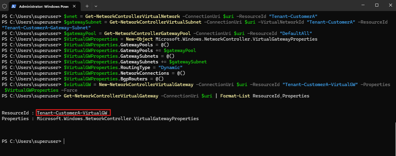
First, we retrieve the existing tenant virtual network, its dedicated Gateway Subnet, and the DefaultAll Gateway Pool and store them in variables for the Virtual Gateway configuration:
$vnet = Get-NetworkControllerVirtualNetwork -ConnectionUri $uri -ResourceId "Tenant-CustomerA"
$gatewaySubnet = Get-NetworkControllerVirtualSubnet -ConnectionUri $uri -VirtualNetworkId "Tenant-CustomerA" -ResourceId "Tenant-CustomerA-Gateway-Subnet"
$gatewayPool = Get-NetworkControllerGatewayPool -ConnectionUri $uri -ResourceId "DefaultAll"
Now we create the actual tenant Virtual Gateway object and bind it to the existing DefaultAll Gateway Pool and our dedicated Tenant-CustomerA-Gateway-Subnet:
$VirtualGWProperties = New-Object Microsoft.Windows.NetworkController.VirtualGatewayProperties
$VirtualGWProperties.GatewayPools = @()
$VirtualGWProperties.GatewayPools += $gatewayPool
$VirtualGWProperties.GatewaySubnets = @()
$VirtualGWProperties.GatewaySubnets += $gatewaySubnet
$VirtualGWProperties.RoutingType = "Dynamic"
$VirtualGWProperties.NetworkConnections = @()
$VirtualGWProperties.BgpRouters = @()
We then create the Virtual Gateway for our tenant:
$virtualGW = New-NetworkControllerVirtualGateway -ConnectionUri $uri -ResourceId "Tenant-CustomerA-VirtualGW" -Properties $VirtualGWProperties -Force
Microsoft uses this same model: the Virtual Gateway references a Gateway Pool and a virtual subnet used for routing between the gateway and the tenant virtual network.
Finally, we verify the configuration with Get-NetworkControllerVirtualGateway. The returned Tenant-CustomerA-VirtualGW confirms that the tenant-specific Virtual Gateway has been successfully created and registered with the Network Controller.
Get-NetworkControllerVirtualGateway -ConnectionUri $uri | Format-List ResourceId,Properties
Creating the First SDN Gateway Connection
With the SDN Gateway successfully deployed and validated, we can now connect our isolated Tenant-CustomerA HNV network to networks outside the virtualized SDN fabric. For this, we create our first Gateway Connection and use Layer 3 (L3) forwarding to provide routed connectivity through the SDN Gateway.
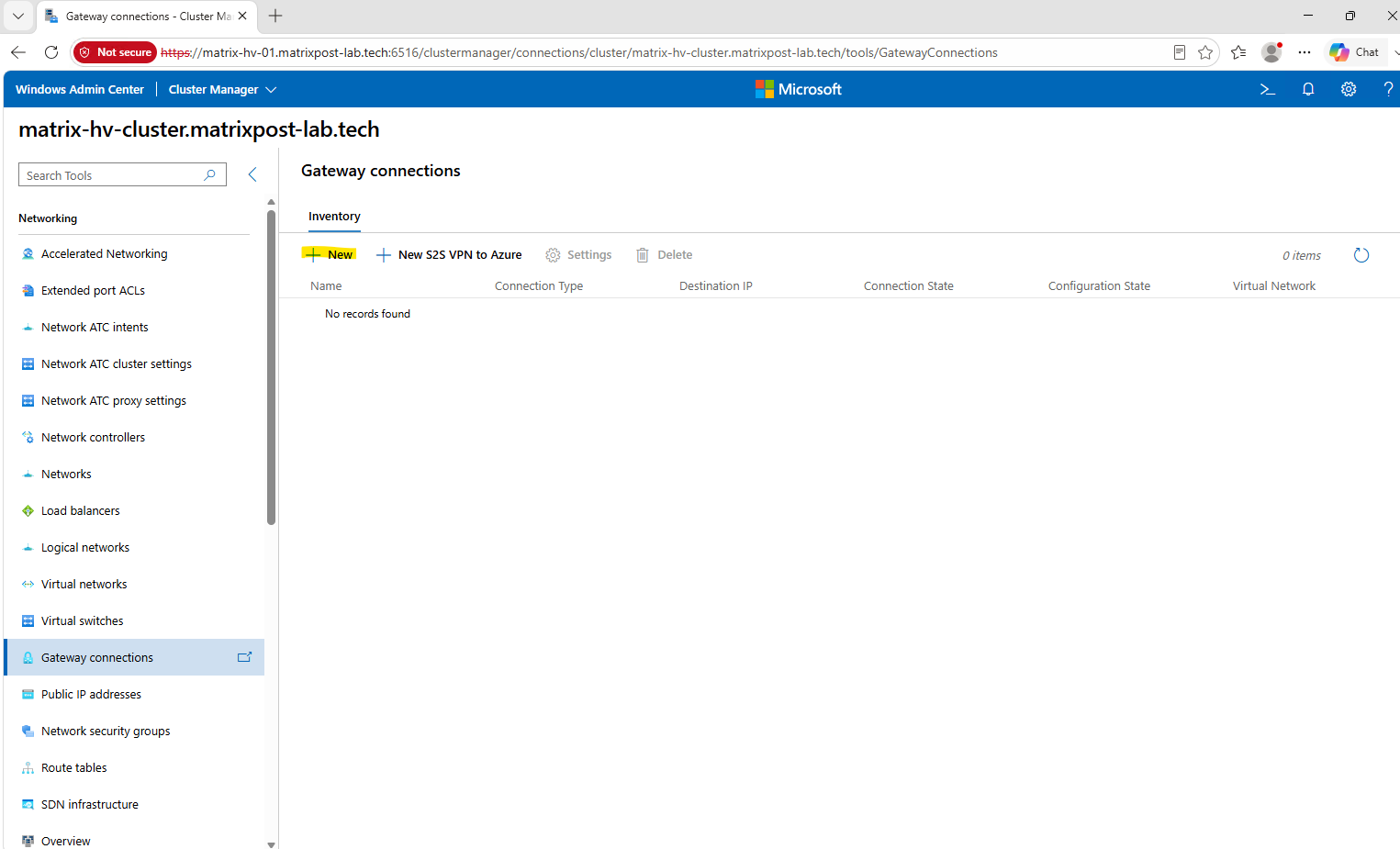
In Windows Admin Center, open Gateway connections from the left navigation. Here we can create and manage the connections that associate an HNV virtual network with the deployed SDN Gateway and provide connectivity beyond the tenant overlay network.
The Gateway connections view is currently empty because no tenant network has yet been connected to the SDN Gateway. To create our first connection for Tenant-CustomerA, click New.
The SDN Gateway supports IPsec for encrypted site-to-site VPN connections, GRE for routed tunnel connectivity without encryption, and L3 for direct Layer-3 forwarding without tunneling.
For our scenario, we select L3 to provide routed connectivity between the HNV tenant network and the external network.
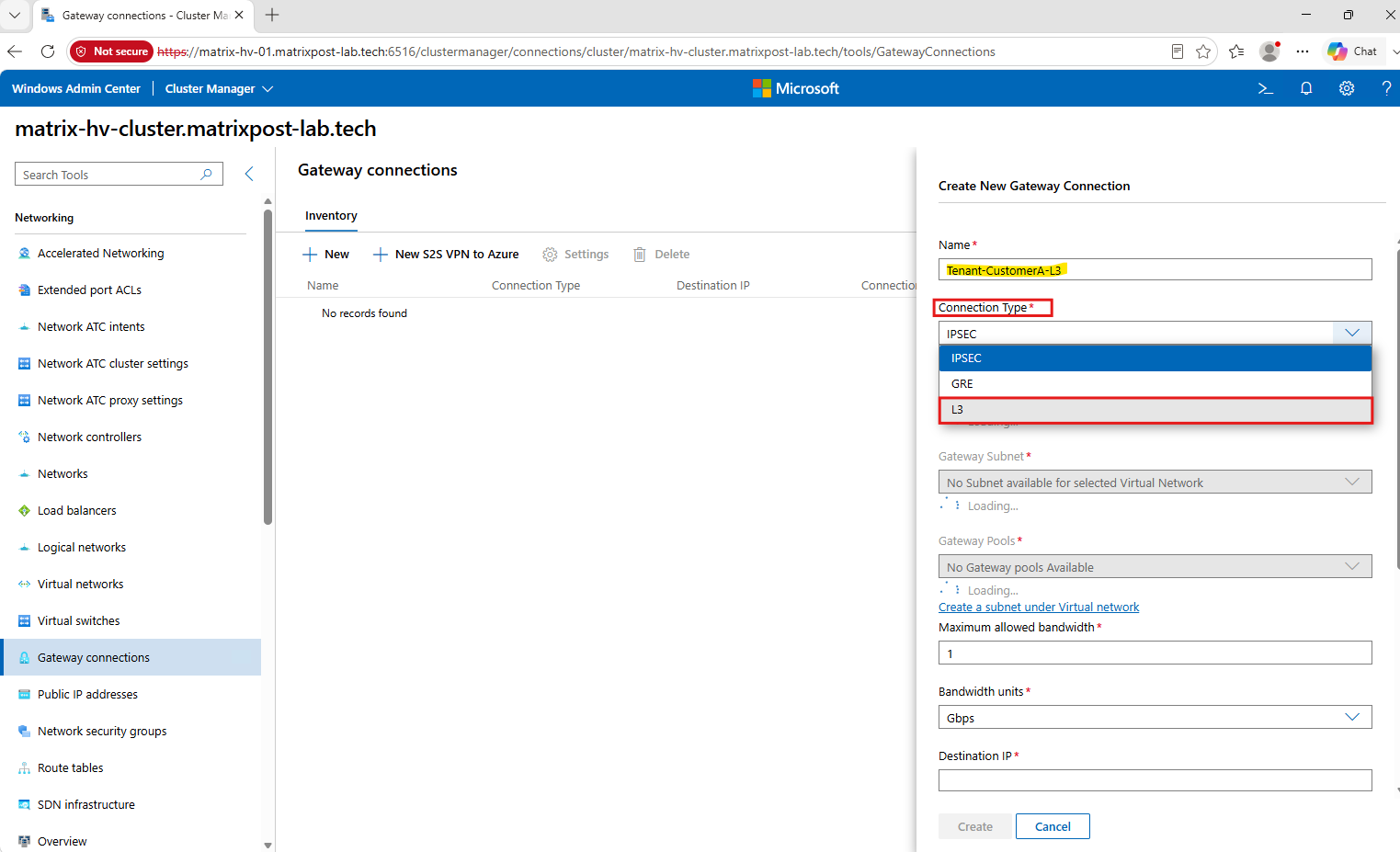
Because Windows Admin Center still cannot enumerate the existing tenant virtual network, Gateway Subnet, and Gateway Pool, we continue the Gateway Connection configuration directly through the Network Controller PowerShell cmdlets.
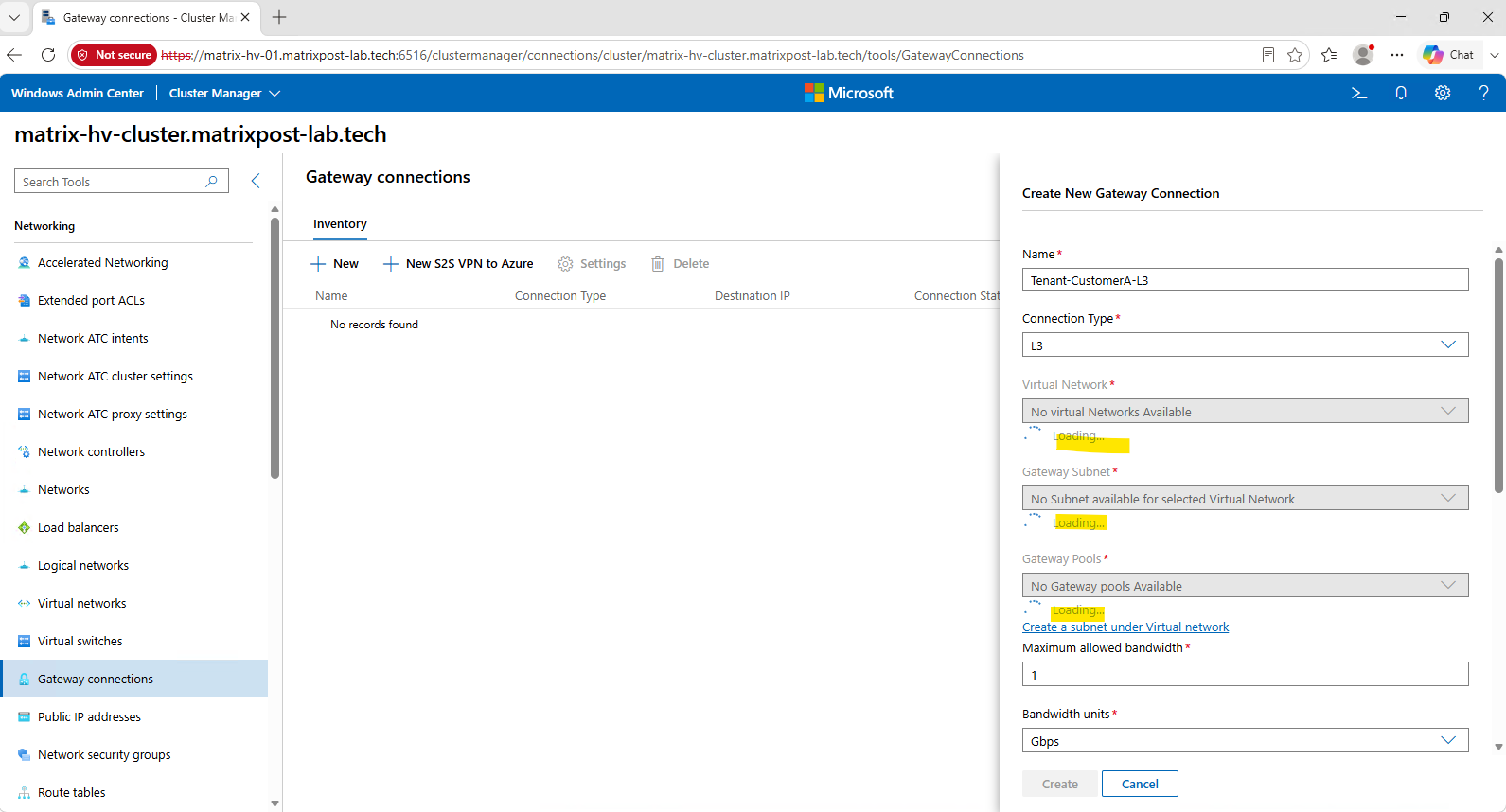
To create an L3 Gateway Connection, the SDN Gateway needs a physical Layer-3 path from the tenant’s Virtual Gateway to an external router. We therefore need a dedicated L3 transit network between our Matrix-SDN-GW1 Gateway VM and pfSense, which will act as the external next-hop router.
This transit network is separate from both the tenant HNV network and the HNV Provider Address network on VLAN 30. The SDN Gateway will receive an IP address on this transit subnet, while pfSense will receive another IP address on the same subnet; these two addresses form the Layer-3 connection between the SDN fabric and the physical network.
Tenant-CustomerA
192.168.100.0/24
        │
        ▼
Tenant Virtual Gateway
        │
        ▼
Matrix-SDN-GW1
        │
        │  Dedicated L3 transit subnet / VLAN
        ▼
      pfSense
        │
        ▼
 External networks / Internet
Next, we configure VLAN 40 as an allowed tagged VLAN on the physical switch trunk ports used by vSwitch-VM. This VLAN will provide the dedicated L3 transit network (10.0.40.0/24) between the SDN Gateway and pfSense.
Remember,
vSwitch-VMis our SDN data-plane switch backed by the VM-A and VM-B SET uplinks, whose physical switch ports are configured as trunks. These trunks already carry the HNV Provider network on VLAN 30 and now additionally carry our L3 transit network on VLAN 40.For the complete configuration of
vSwitch-VMand its Switch Embedded Teaming (SET) uplinksVM-AandVM-B, see my Microsoft Hyper-V Networking Best Practices – Part 2 article.
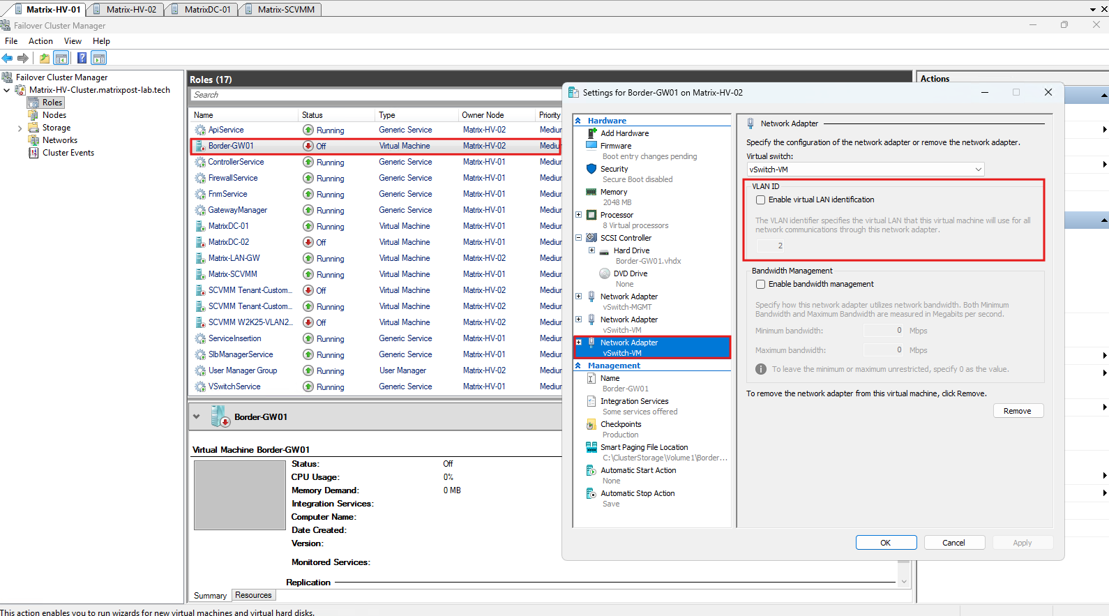
Next, we add a third network adapter to our pfSense VM Border-GW01 and connect it to vSwitch-VM. We deliberately leave VLAN identification disabled in the Hyper-V GUI. The interface inside pfSense will use the physical interface directly, without creating a VLAN subinterface such as hn2.40.
Because vSwitch-VM is managed by the Windows Server SDN infrastructure, the VLAN assignment and forwarding policy will later be configured through Hyper-V and the Network Controller/VFP policy. In our case, this interface will be associated with the SDN-L3-Transit network on VLAN 40.
vSwitch-VM is our SDN data-plane switch connected to physical trunk ports.
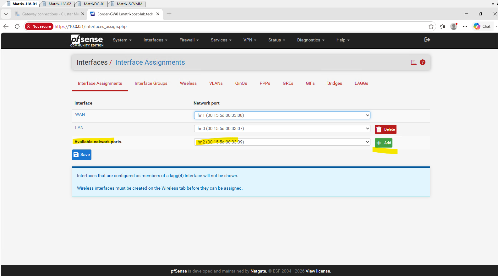
In pfSense, open Interfaces → Interface Assignments. The newly added Hyper-V network adapter appears as an available network port, in our case hn2. Select hn2 and click Add to assign the physical interface directly to pfSense.
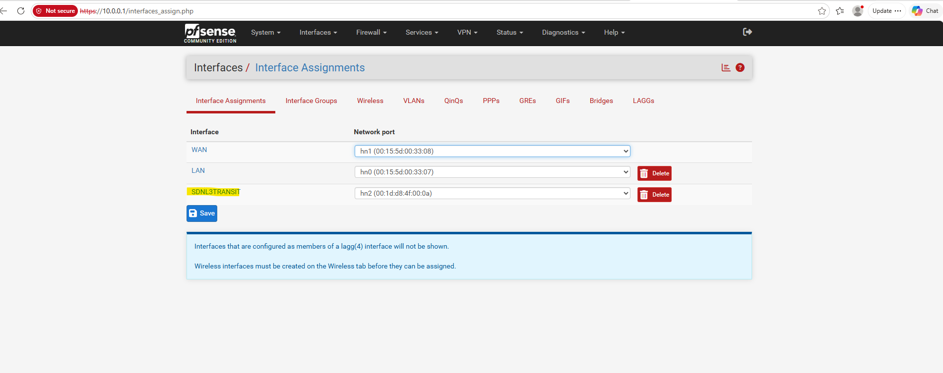
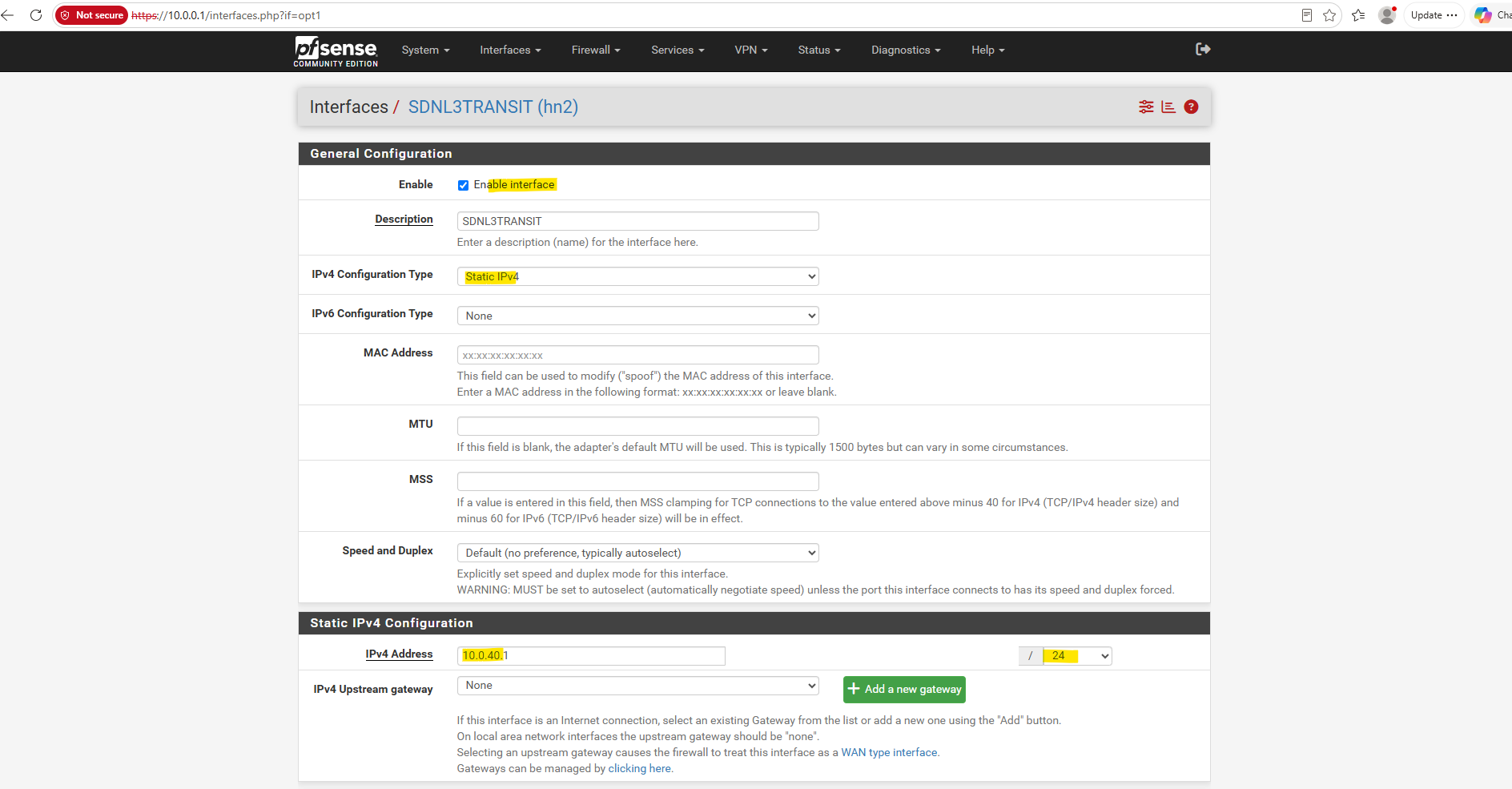
We rename OPT1 to SDNL3TRANSIT. This interface is connected directly to our SDN data-plane switch vSwitch-VM and will serve as the external Layer-3 transit interface between pfSense and the Microsoft SDN Gateway.
We enable SDNL3TRANSIT and will configure it with the IP address 10.0.40.1/24.
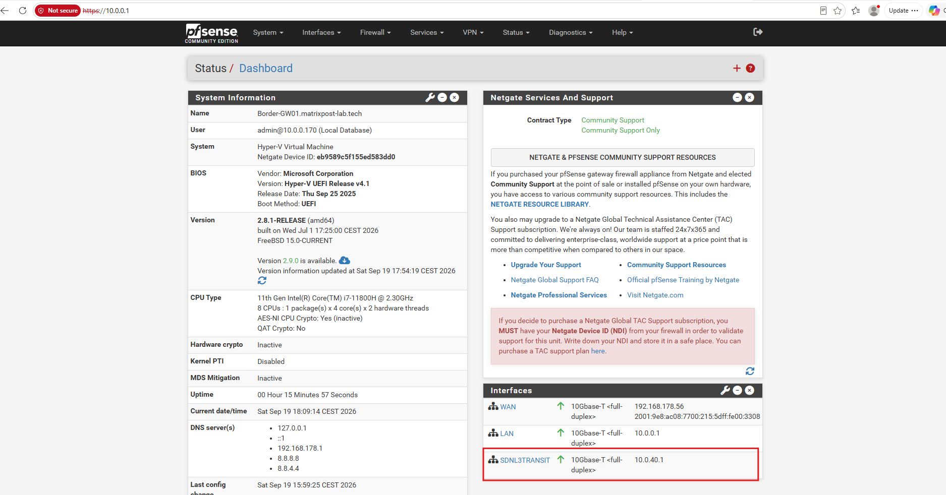
The pfSense dashboard now shows SDNL3TRANSIT with the address 10.0.40.1. The VLAN 40 association itself is handled on the Hyper-V/SDN side rather than inside pfSense.
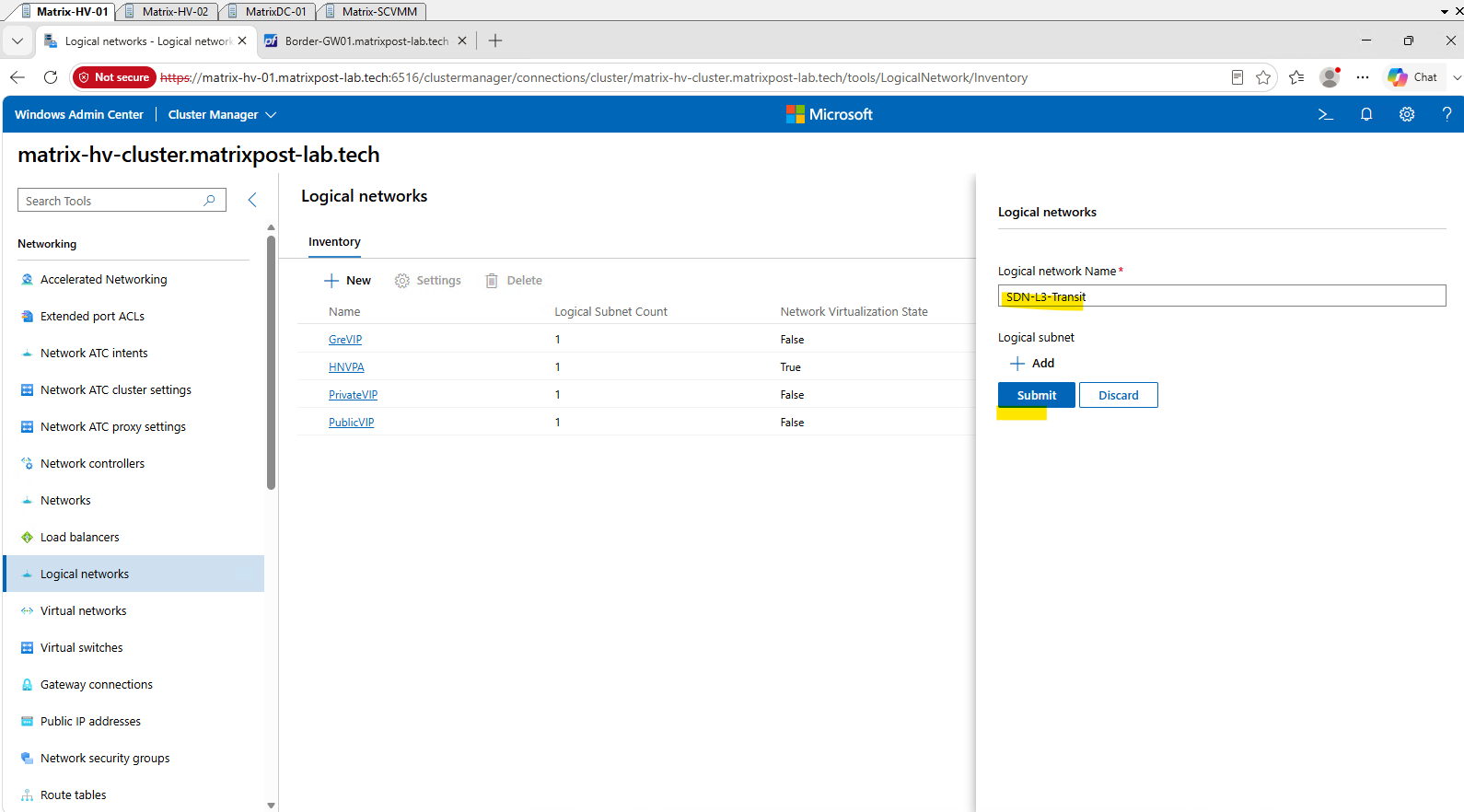
Next we need to represent this new physical L3 transit network in Windows SDN. In Windows Admin Center → Logical networks, we create a new logical network for VLAN 40 / 10.0.40.0/24; this is the network that will later appear as the L3 Logical Network in the Gateway Connection wizard.
Click New and create a logical network named SDN-L3-Transit.
This logical network will represent our dedicated VLAN 40 /
10.0.40.0/24network between the Microsoft SDN Gateway and pfSense.
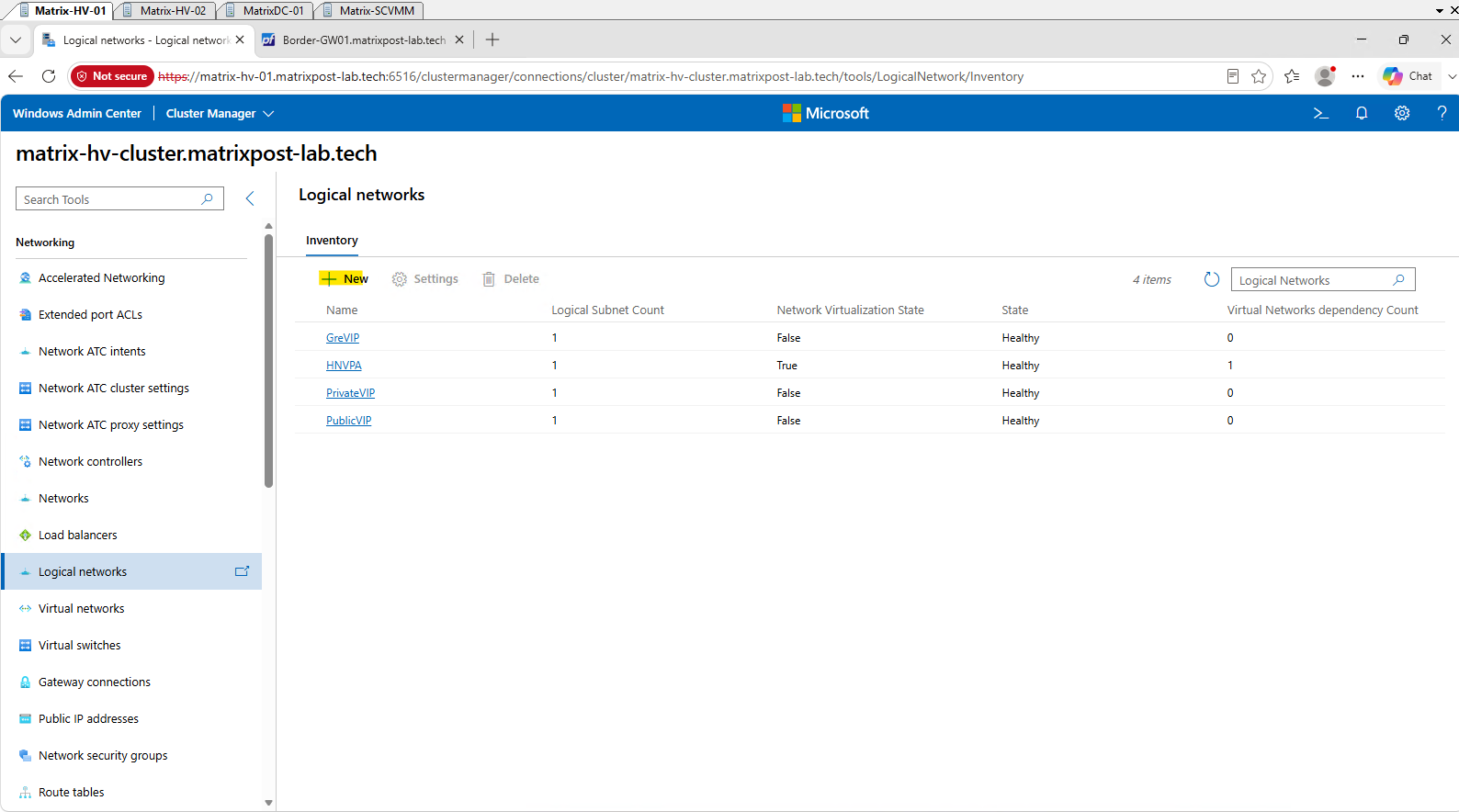
Click on Submit.
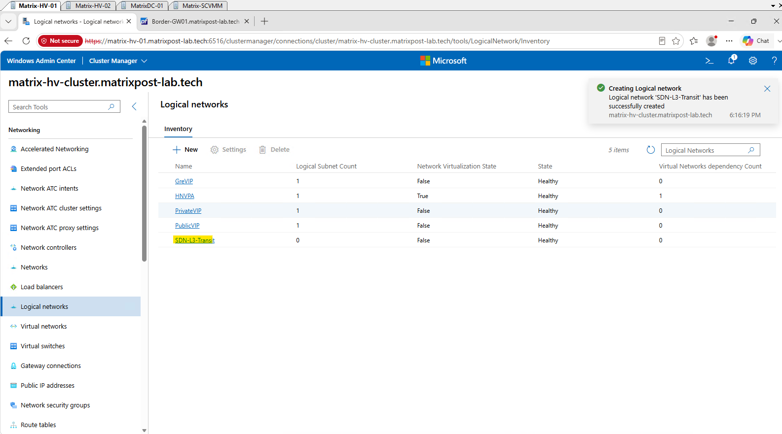
The new SDN-L3-Transit logical network has been created successfully and is Healthy. Its Logical Subnet Count is still 0, so next we open it and create the 10.0.40.0/24 logical subnet on VLAN 40.
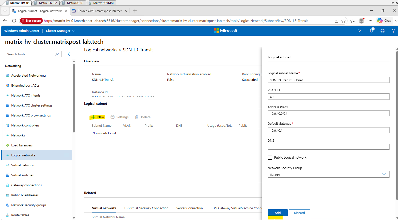
Click on New to dd the logical subnet SDN-L3-Transit-Subnet with VLAN 40, the address prefix 10.0.40.0/24, and 10.0.40.1 as the default gateway.
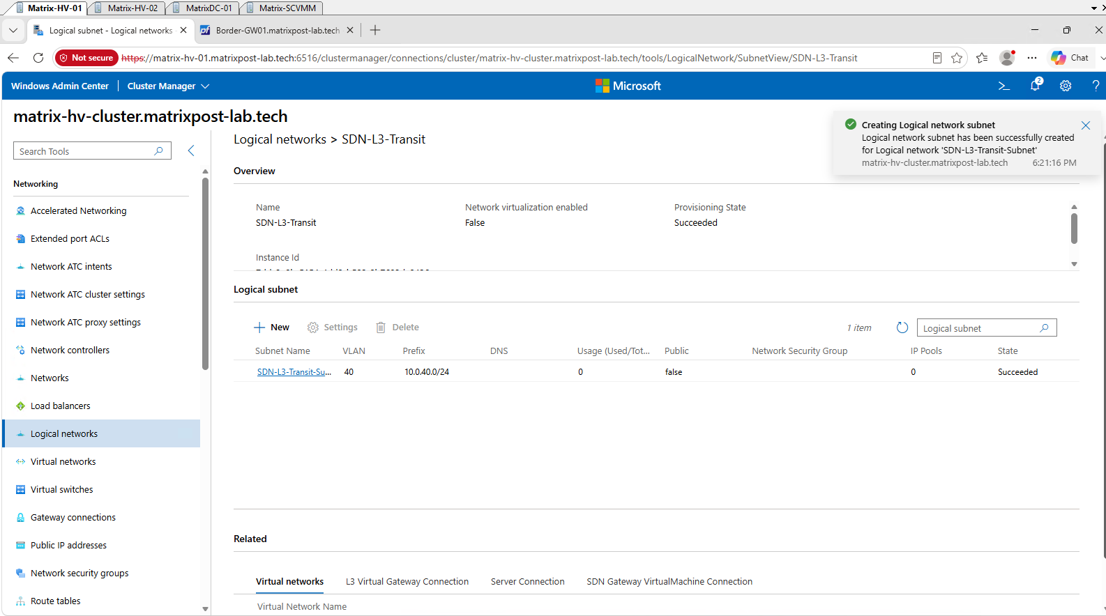
The logical subnet SDN-L3-Transit-Subnet has now been successfully created with VLAN 40 and the 10.0.40.0/24 address prefix.
Now that the L3 logical network and subnet exist, we can finally build the actual L3 Gateway Connection in Network Controller.
First, retrieve the logical network and the existing Virtual Gateway:
$vlanNetwork = Get-NetworkControllerLogicalNetwork -ConnectionUri $uri -ResourceId "SDN-L3-Transit"
$virtualGW = Get-NetworkControllerVirtualGateway -ConnectionUri $uri -ResourceId "Tenant-CustomerA-VirtualGW"
Now we create the L3 network connection object and bind it to our SDN-L3-Transit logical subnet. We use 10.0.40.2/24 as the local SDN Gateway address and 10.0.40.1 as the pfSense peer address.
$nwConnectionProperties = New-Object Microsoft.Windows.NetworkController.NetworkConnectionProperties
$nwConnectionProperties.ConnectionType = "L3"
$nwConnectionProperties.OutboundKiloBitsPerSecond = 10000
$nwConnectionProperties.InboundKiloBitsPerSecond = 10000
$nwConnectionProperties.GreConfiguration = New-Object Microsoft.Windows.NetworkController.GreConfiguration
$nwConnectionProperties.L3Configuration = New-Object Microsoft.Windows.NetworkController.L3Configuration
$nwConnectionProperties.L3Configuration.VlanSubnet = $vlanNetwork.Properties.Subnets[0]
$nwConnectionProperties.IPAddresses = @()
$localIPAddress = New-Object Microsoft.Windows.NetworkController.CidrIPAddress
$localIPAddress.IPAddress = "10.0.40.2"
$localIPAddress.PrefixLength = 24
$nwConnectionProperties.IPAddresses += $localIPAddress
$nwConnectionProperties.PeerIPAddresses = @("10.0.40.1")
Next we add the route that should be reachable through this L3 connection. Since pfSense is our upstream router toward the rest of the lab and Internet, we use a default route:
$nwConnectionProperties.Routes = @()
$ipv4Route = New-Object Microsoft.Windows.NetworkController.RouteInfo
$ipv4Route.DestinationPrefix = "0.0.0.0/0"
$ipv4Route.Metric = 10
$nwConnectionProperties.Routes += $ipv4Route
Then we create the actual L3 Gateway Connection:
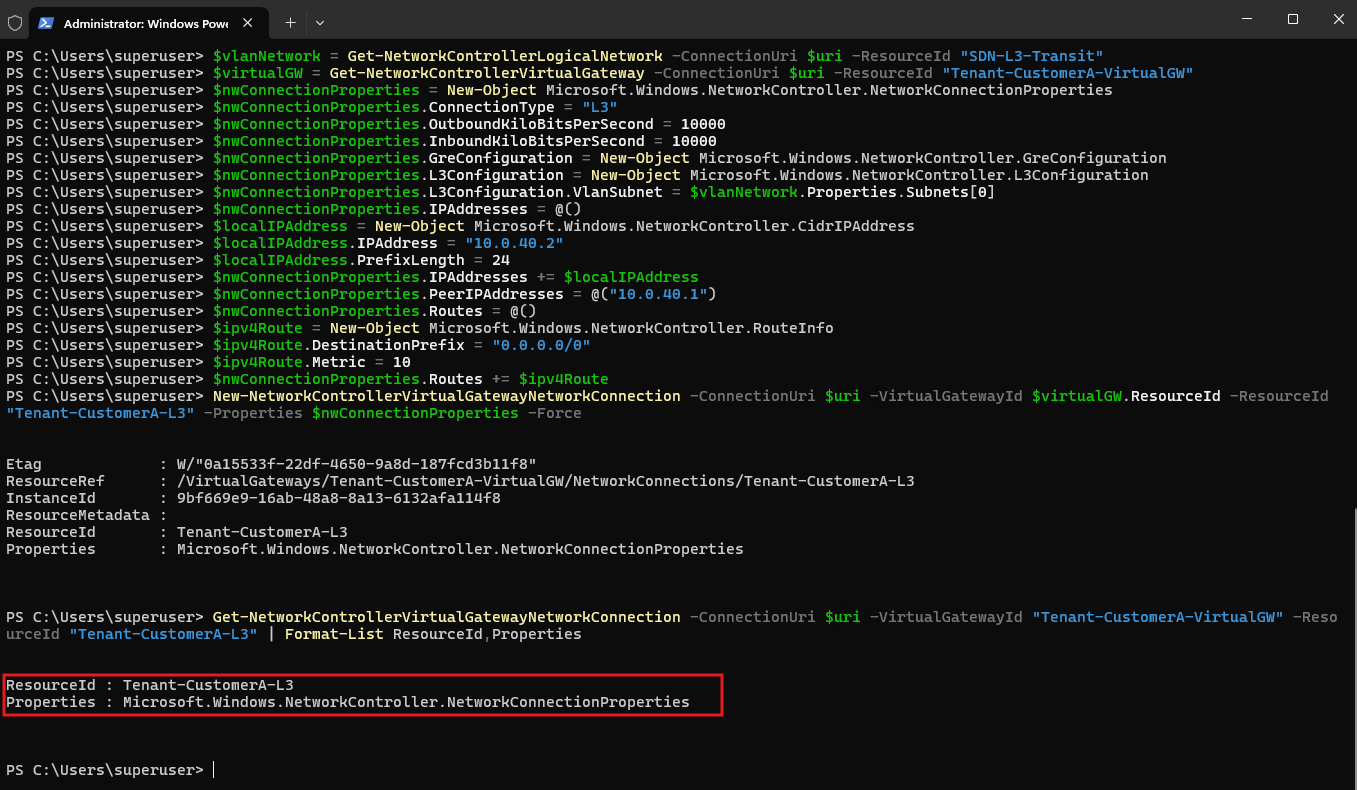
New-NetworkControllerVirtualGatewayNetworkConnection -ConnectionUri $uri -VirtualGatewayId $virtualGW.ResourceId -ResourceId "Tenant-CustomerA-L3" -Properties $nwConnectionProperties -Force
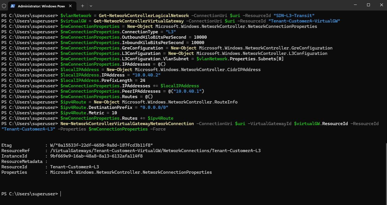
Next, we verify that the new L3 Gateway Connection was created successfully and that Network Controller stored the expected L3 settings:
The returned
Tenant-CustomerA-L3resource confirms that the L3 Gateway Connection has been successfully created and associated with the tenant Virtual Gateway.
Get-NetworkControllerVirtualGatewayNetworkConnection -ConnectionUri $uri -VirtualGatewayId "Tenant-CustomerA-VirtualGW" -ResourceId "Tenant-CustomerA-L3" | Format-List ResourceId,Properties
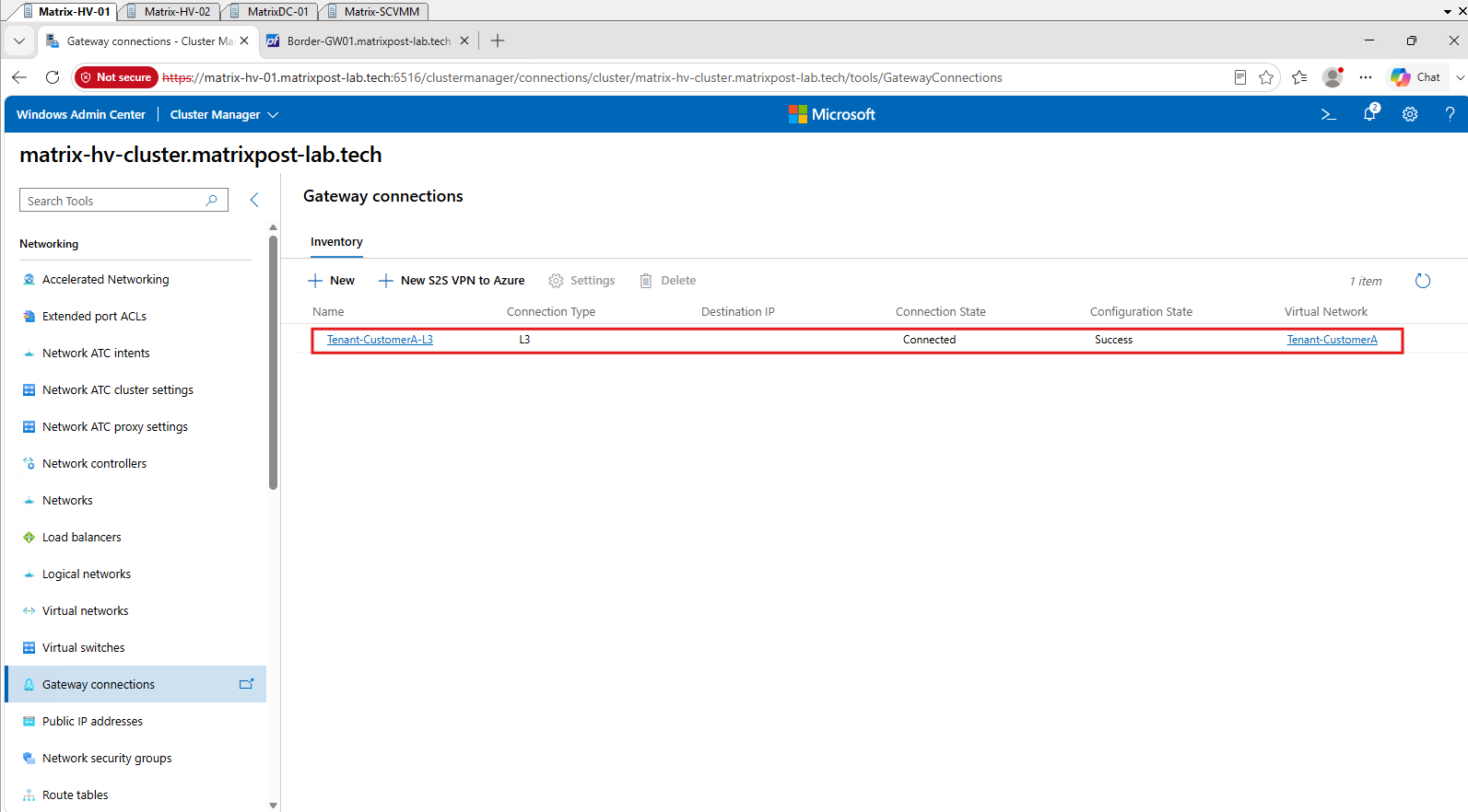
Back in Windows Admin Center, the newly created Tenant-CustomerA-L3 Gateway Connection is now visible and associated with the Tenant-CustomerA virtual network.
Both Connection State: Connected and Configuration State: Success confirm that the L3 connection has been successfully provisioned by the SDN infrastructure.
Next we need to go back to pfSense. The SDN Gateway knows to send external traffic toward pfSense via 10.0.40.1, but pfSense must also know that the tenant network 192.168.100.0/24 is reachable through the SDN Gateway at 10.0.40.2.
In pfSense, go to System → Routing → Gateways and add 10.0.40.2 on the SDNL3TRANSIT interface as a gateway.
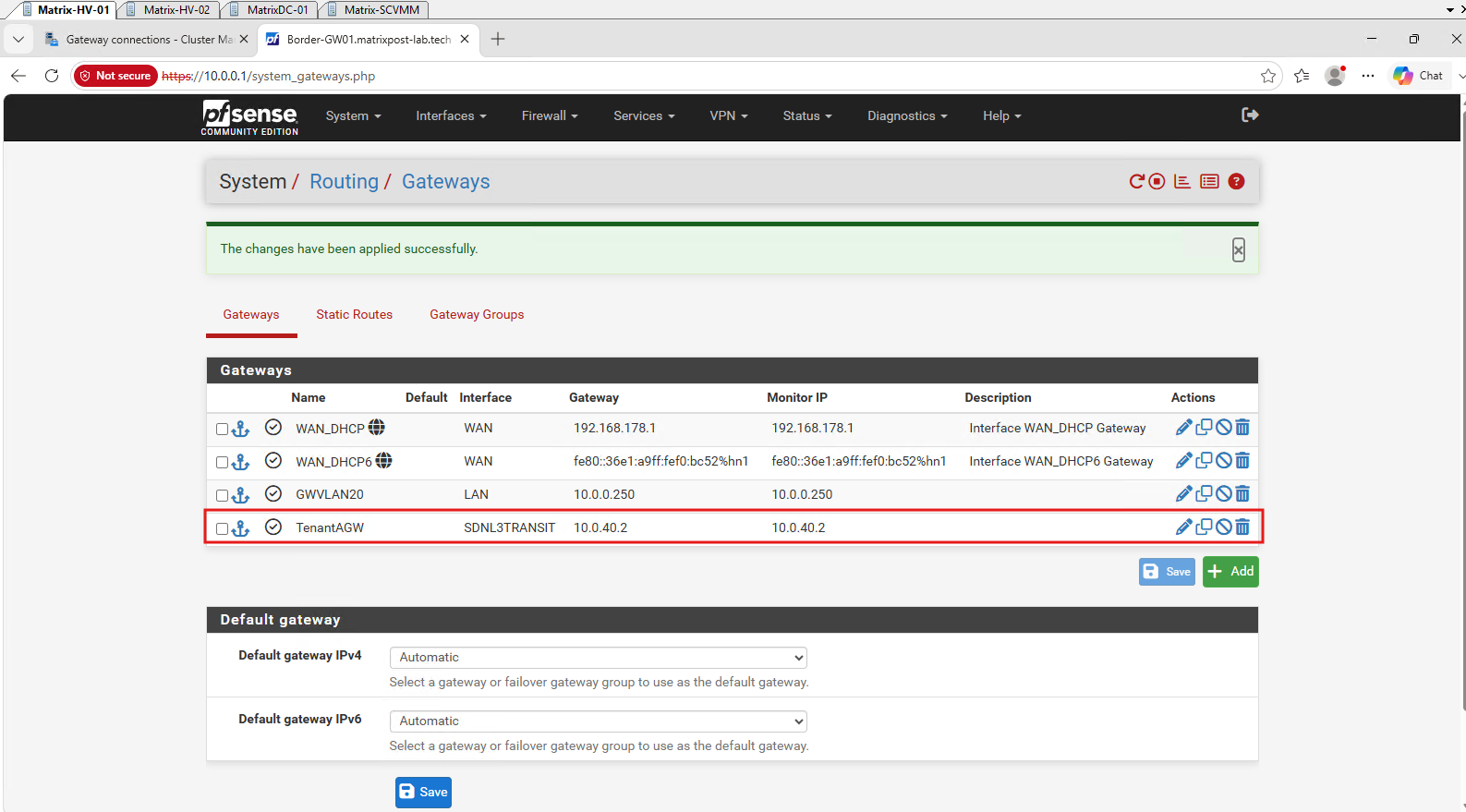
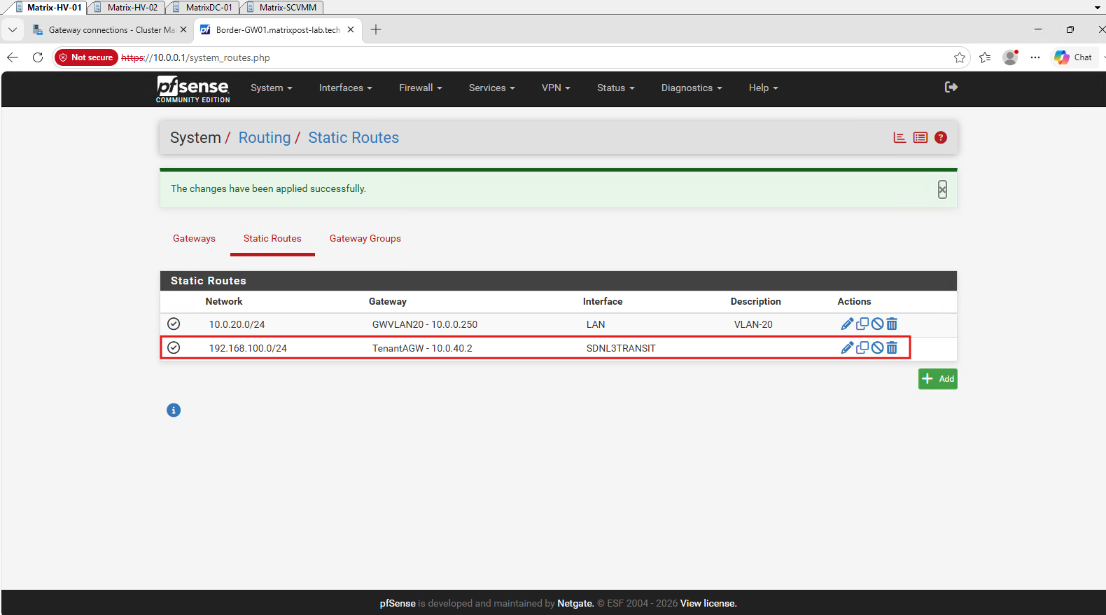
After that, we’ll use this gateway for a static route to 192.168.100.0/24.
This provides the required return route from pfSense through the SDN Gateway back into
Tenant-CustomerA.
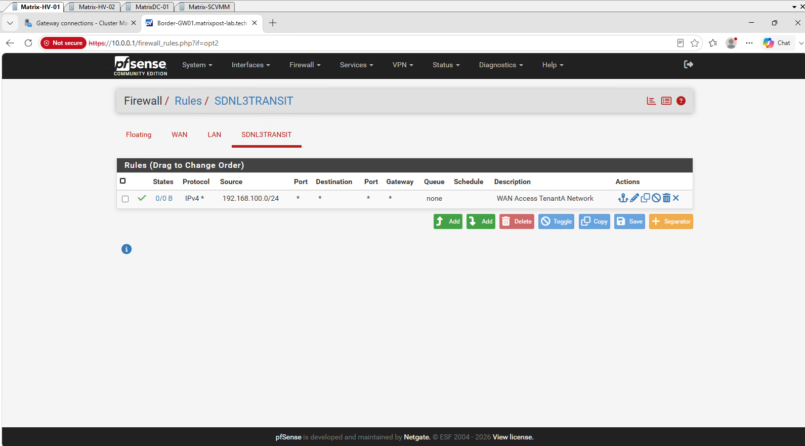
Next we need to allow the tenant traffic through the pfSense firewall. Go to Firewall → Rules → SDNL3TRANSIT and add a rule allowing IPv4 traffic from 192.168.100.0/24 to the required destinations; for our initial connectivity test, we can allow it to any.
Associating the pfSense Transit Adapter with the Network Controller and VFP
With the pfSense-side routing and firewall configuration in place, one additional step is required on the Windows Server SDN side.
Because the pfSense transit adapter is connected to the SDN-managed vSwitch-VM, simply assigning the adapter to VLAN 40 is not sufficient. The corresponding VM port must also be represented in the Network Controller and associated with the appropriate VFP port profile.
Without this association, VFP keeps the VM port in a blocked state, preventing traffic from reaching or leaving the pfSense transit interface.
Note: Because
vSwitch-VMis managed by Windows Server SDN, VFP controls its VM ports based on policies programmed by the Network Controller.Unlike on a conventional Hyper-V switch, a connected VM adapter therefore requires the appropriate SDN/VFP policy state; otherwise, VFP may keep the port blocked.
The important point here is that the pfSense transit interface itself remains untagged. Instead of creating a VLAN 40 subinterface inside pfSense, the physical
hn2interface is used directly, while the Network Controller programs the required VLAN and forwarding policy into the VFP layer of the Hyper-V virtual switch. This follows the SDN data-plane model: the external appliance provides the Layer-3 endpoint, while Hyper-V, Network Controller, and VFP control how its VM port is attached to the SDN logical network.
First, we configure the pfSense SDNL3TRANSIT VM network adapter for VLAN 40. Because VLAN handling is performed by Hyper-V/VFP, pfSense itself continues to use the untagged hn2 interface.
Since all pfSense adapters have the same friendly name, identify the correct adapter by its MAC address:
$pfNic = Get-VMNetworkAdapter -VMName "Border-GW01" | Where-Object MacAddress -eq "001DD84F000A"
Then assign VLAN 40 through Hyper-V isolation:
Set-VMNetworkAdapterVlanconfigures traditional Layer 2 VLAN tagging for a Hyper-V virtual network adapter, whereasSet-VMNetworkAdapterIsolationmanages advanced multitenancy and software-defined networking (SDN) isolation policies like Hyper-V Network Virtualization (HNV) or VLAN-based SDN routing.
$pfNic | Set-VMNetworkAdapterIsolation -IsolationMode Vlan -DefaultIsolationID 40 -AllowUntaggedTraffic $true
Verify:
$pfNic | Get-VMNetworkAdapterIsolation | Format-List IsolationMode,DefaultIsolationID,AllowUntaggedTraffic,MultiTenantStack
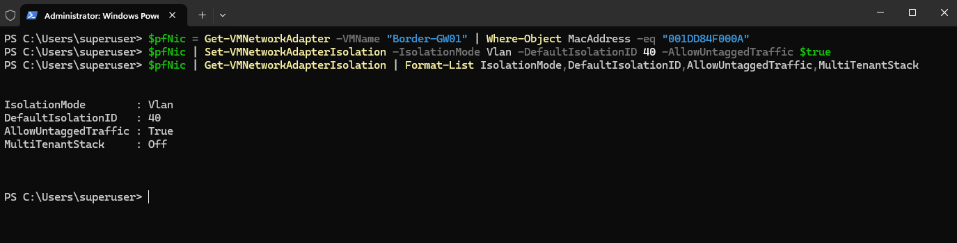
The pfSense transit adapter is now associated with VLAN 40 at the Hyper-V/VFP layer, while pfSense itself continues to send and receive untagged traffic through hn2. However, the adapter is not yet fully provisioned for the SDN-managed switch; next, we create the corresponding Network Controller NetworkInterface and bind it to the VM port.
Next, we create a NetworkInterface object in the Network Controller for the pfSense SDNL3TRANSIT adapter. This associates its MAC and IP configuration with the previously created SDN-L3-Transit-Subnet.
$uri = "https://nc.matrixpost-lab.tech"
$logicalnet = Get-NetworkControllerLogicalNetwork -ConnectionUri $uri -ResourceId "SDN-L3-Transit"

$vmnicproperties = New-Object Microsoft.Windows.NetworkController.NetworkInterfaceProperties
$vmnicproperties.PrivateMacAddress = "001DD84F000A"
$vmnicproperties.PrivateMacAllocationMethod = "Static"
$vmnicproperties.IsPrimary = $true

$vmnicproperties.DnsSettings = New-Object Microsoft.Windows.NetworkController.NetworkInterfaceDnsSettings
$vmnicproperties.DnsSettings.DnsServers = $logicalnet.Properties.Subnets[0].DnsServers

$ipconfiguration = New-Object Microsoft.Windows.NetworkController.NetworkInterfaceIpConfiguration
$ipconfiguration.ResourceId = "Border-GW01-Transit-IP1"
$ipconfiguration.Properties = New-Object Microsoft.Windows.NetworkController.NetworkInterfaceIpConfigurationProperties
$ipconfiguration.Properties.PrivateIPAddress = "10.0.40.1"
$ipconfiguration.Properties.PrivateIPAllocationMethod = "Static"

$ipconfiguration.Properties.Subnet = New-Object Microsoft.Windows.NetworkController.Subnet
$ipconfiguration.Properties.Subnet.ResourceRef = $logicalnet.Properties.Subnets[0].ResourceRef

$vmnicproperties.IpConfigurations = @($ipconfiguration)

$nic = New-NetworkControllerNetworkInterface -ConnectionUri $uri -ResourceId "Border-GW01-Transit-NIC" -Properties $vmnicproperties
Verify that the NetworkInterface was successfully provisioned in the Network Controller:
Get-NetworkControllerNetworkInterface -ConnectionUri $uri -ResourceId "Border-GW01-Transit-NIC" | Select-Object -ExpandProperty Properties | Format-List PrivateMacAddress,PrivateMacAllocationMethod,IsPrimary,ProvisioningState
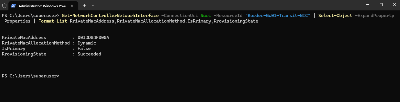
Although the NetworkInterface is now successfully provisioned in the Network Controller, the actual Hyper-V VM port still needs to be associated with this SDN object.
For this purpose, we retrieve the NetworkInterface and the pfSense transit adapter and attach the corresponding Microsoft SDN VFP port profile.
$nic = Get-NetworkControllerNetworkInterface -ConnectionUri $uri -ResourceId "Border-GW01-Transit-NIC"
$pfNic = Get-VMNetworkAdapter -VMName "Border-GW01" | Where-Object MacAddress -eq "001DD84F000A"

$FeatureId = "9940cd46-8b06-43bb-b9d5-93d50381fd56"
$PortProfile = Get-VMSystemSwitchExtensionPortFeature -FeatureId $FeatureId
$PortProfile.SettingData.ProfileId = "{$($nic.InstanceId)}"
$PortProfile.SettingData.ProfileData = 2
$PortProfile.SettingData.ProfileName = "Microsoft SDN Port"
$PortProfile.SettingData.VendorId = "{1FA41B39-B444-4E43-B35A-E1F7985FD548}"

Add-VMSwitchExtensionPortFeature -VMNetworkAdapter $pfNic -VMSwitchExtensionFeature $PortProfile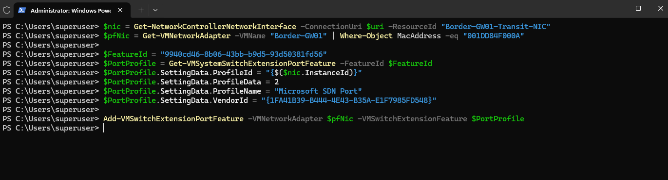
We can verify the resulting VFP state directly on the Hyper-V host.
First, use vfpctrl /list-vmswitch-port to identify the VFP port belonging to the pfSense transit adapter by its MAC address 00-1D-D8-4F-00-0A.
vfpctrl /list-vmswitch-port | Select-String -Pattern "00-1D-D8-4F-00-0A" -Context 16,16
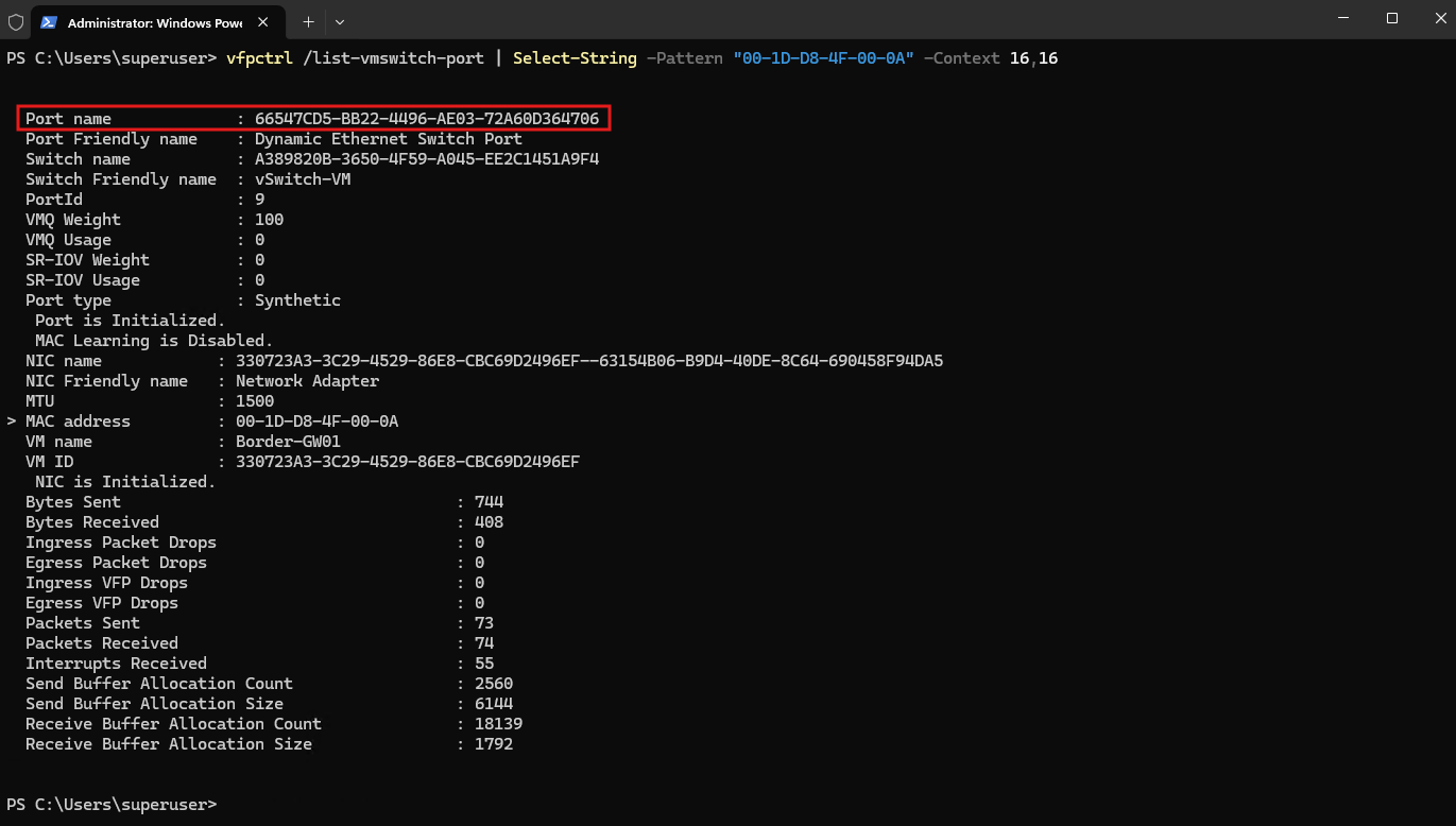
Using the MAC address of the pfSense transit adapter, we identify its corresponding VFP port on vSwitch-VM.
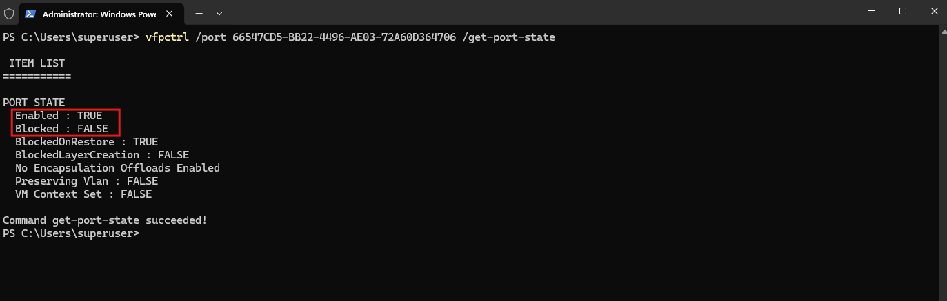
The VFP port is now enabled and no longer blocked, confirming that the pfSense transit adapter has been successfully associated with the SDN policy. Traffic can now be forwarded between the SDN Gateway and pfSense over the SDN-L3-Transit network on VLAN 40.
vfpctrl /port 66547CD5-BB22-4496-AE03-72A60D364706 /get-port-state
Verifying End-to-End HNV Connectivity Through the SDN Gateway
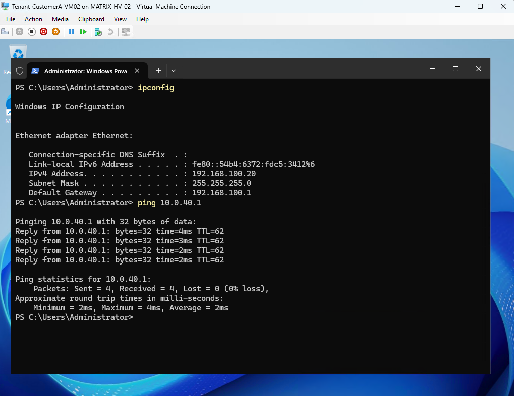
Finally, we verify the end-to-end connectivity from our tenant VM. Tenant-CustomerA-VM02 uses the Customer Address 192.168.100.20/24 with the HNV default gateway 192.168.100.1.
A ping to the pfSense
SDNL3TRANSITinterface at10.0.40.1succeeds, confirming that traffic is routed from the isolated HNV tenant network through the Microsoft SDN Gateway to the external Layer-3 transit network.
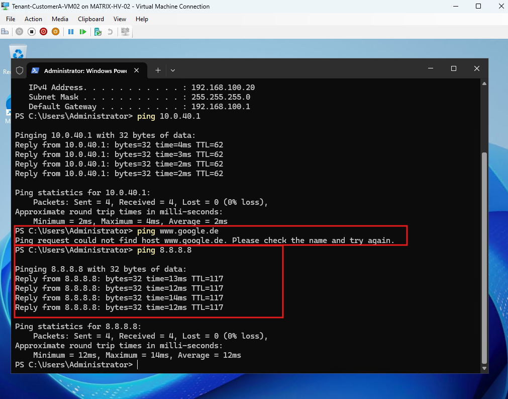
The VM can also successfully reach the Internet at 8.8.8.8, confirming end-to-end routing through the Microsoft SDN Gateway and pfSense.
DNS resolution is not available because no DNS server has been configured for this tenant network, which is outside the scope of this article.
Capturing HNV Tenant WAN Traffic Through the SDN Gateway and pfSense with Wireshark
To better understand how HNV tenant traffic reaches the external network, we will capture the traffic with Wireshark and follow a packet along the complete path through the HNV overlay, SDN Gateway, and pfSense toward the WAN.
Tenant VM (HV-02)
192.168.100.20
      │
      │ VXLAN / VLAN 30 across physical network
      ▼
SDN Gateway (HV-01)
      │
      │ decapsulates HNV traffic
      │ routes into L3 transit
      ▼
VLAN 40 across physical network
      │
      ▼
pfSense (HV-02)
10.0.40.1
      │
      ▼
WAN / Internet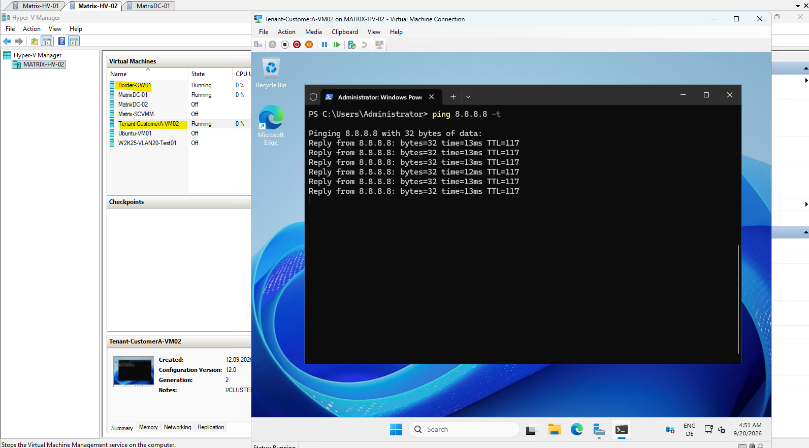
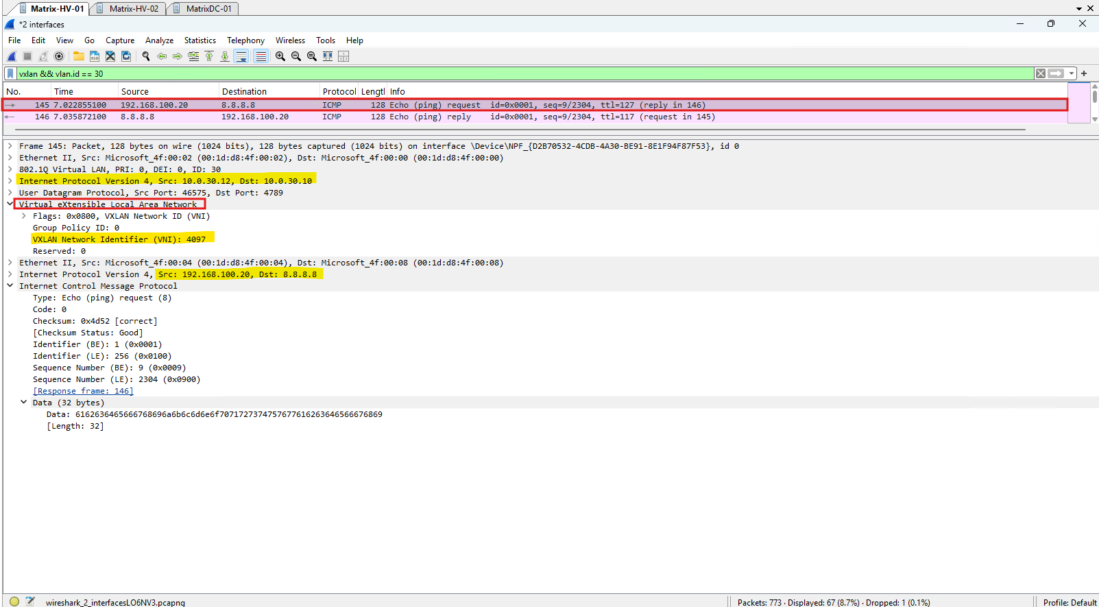
The capture on Matrix-HV-01 shows the ICMP Echo Request from our tenant VM being transported across the physical network using HNV/VXLAN. The original packet 192.168.100.20 → 8.8.8.8 is encapsulated inside VXLAN VNI 4097 and transported over VLAN 30 from Provider Address 10.0.30.12 on Matrix-HV-02 to 10.0.30.10 on Matrix-HV-01, where the SDN Gateway is running.
In this case, VNI 4097 represents the tenant’s gateway subnet/path toward the SDN Gateway, rather than VNI 4096 used for direct traffic within the
Tenant-CustomerAworkload subnet. The SDN Gateway on Matrix-HV-01 receives this encapsulated packet and then routes it toward the external Layer-3 transit network and pfSense.
vxlan && vlan.id == 30
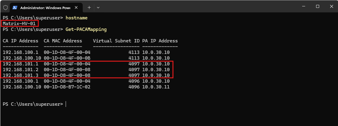
We can correlate the VXLAN VNI 4097 seen in the Wireshark capture with the Virtual Subnet ID 4097 shown by Get-PACAMapping below. The entries using the 192.168.101.x Customer Address space belong to the gateway subnet of Tenant-CustomerA, through which the SDN Gateway provides external connectivity.
Also visible is Virtual Subnet ID 4096, which belongs to the second isolated HNV tenant network created in Part 4. Although that tenant deliberately uses the same overlapping
192.168.100.0/24Customer Address space, HNV assigns it a different virtual subnet/VNI, keeping the two tenant networks isolated.
Get-PACAMapping
Next we show the second stage on Matrix-HV-01: after the SDN Gateway has received and decapsulated the HNV packet, it forwards the original tenant packet onto the Layer-3 transit network VLAN 40 toward pfSense.
The capture now shows the packet after the SDN Gateway has removed the HNV/VXLAN encapsulation. The original tenant packet
192.168.100.20 → 8.8.8.8is forwarded unchanged over the SDN-L3-Transit network on VLAN 40 toward pfSense (10.0.40.1); consequently, there is no VXLAN header anymore at this stage.
icmp && vlan.id == 40 && ip.addr == 8.8.8.8
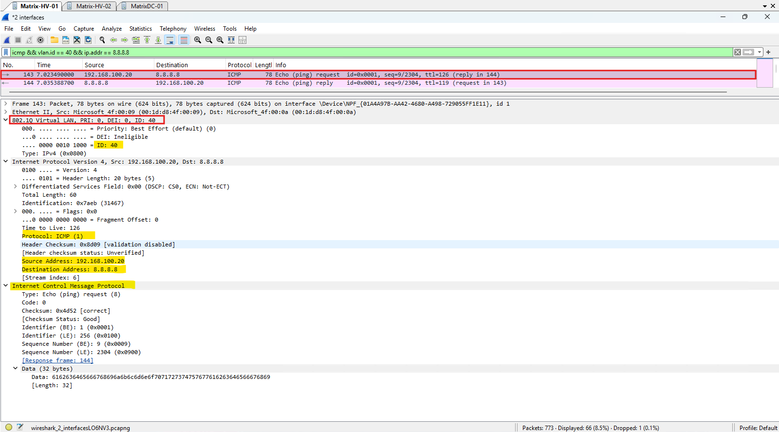
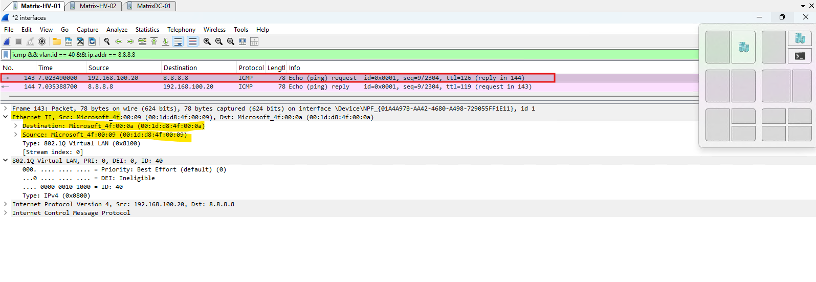
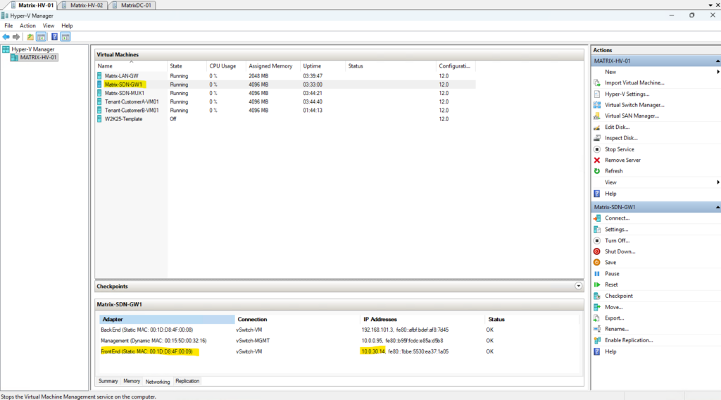
The following screenshots make the forwarding path particularly clear. After the SDN Gateway on Matrix-HV-01 decapsulates the VXLAN traffic, its FrontEnd adapter (00:1D:D8:4F:00:09) shown as MAC Source below highlighted forwards the original tenant packet onto the SDN-L3-Transit network (VLAN 40).
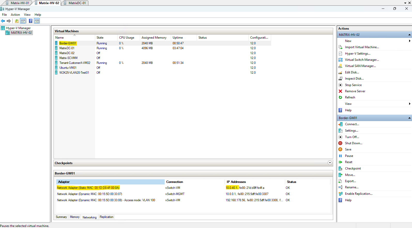
The Wireshark capture shows this frame with the SDN Gateway FrontEnd MAC as the source and the pfSense transit adapter MAC 00:1D:D8:4F:00:0A as the destination.
The corresponding Hyper-V views confirm these MAC addresses and show the two endpoints on different hosts: Matrix-SDN-GW1 on Matrix-HV-01 and Border-GW01/pfSense on Matrix-HV-02, with transit addresses 10.0.40.2 and 10.0.40.1, respectively.
To inspect the packet directly inside the SDN Gateway VM, we connect to Matrix-SDN-GW1 using Remote Desktop (RDP) over its management network and use Wireshark to capture the traffic directly on the gateway.
The SDN Gateway VM uses its Internal interface on the gateway subnet (192.168.101.3/29) for the tenant-side SDN/HNV connectivity, while traffic toward pfSense (10.0.40.1) is forwarded through the configured L3 connection endpoint (10.0.40.2) on the VLAN 40 transit network.
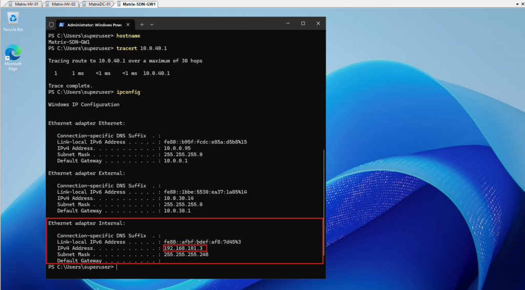
The diagram shows the direct L3 transit connection between the SDN Gateway (10.0.40.2) and pfSense (10.0.40.1), which is why tracert 10.0.40.1 reaches pfSense in a single hop.
The SDN Gateway endpoint
10.0.40.2does not appear inipconfigbecause it is an SDN-programmed L3 connection endpoint rather than a regular IP address assigned to a Windows network adapter.
SDN Gateway (Matrix-SDN-GW1)
L3 Connection: 10.0.40.2/24
             │
             │  VLAN 40
             │  10.0.40.0/24
             ▼
pfSense (Border-GW01)
SDNL3TRANSIT: 10.0.40.1/24
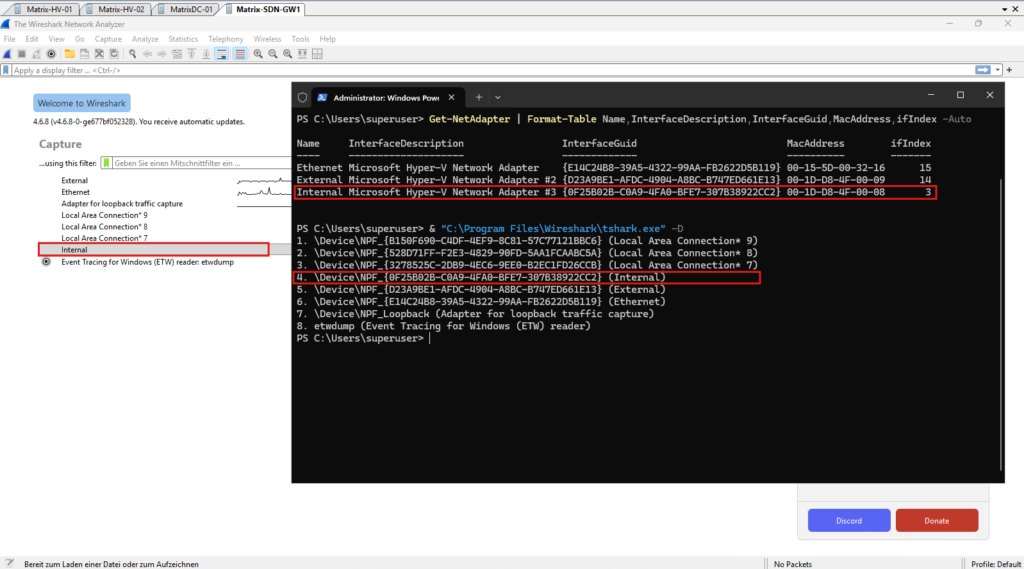
Inside Matrix-SDN-GW1, Wireshark shows the Internal interface corresponding to the 192.168.101.3/29 address displayed by ipconfig.
We start the capture on this interface to inspect the tenant traffic as it passes through the SDN Gateway before being forwarded toward pfSense.
Get-NetAdapter | Format-Table Name,InterfaceDescription,InterfaceGuid,MacAddress,ifIndex -Auto

# get Wireshark's interfaces
& "C:\Program Files\Wireshark\tshark.exe" -D
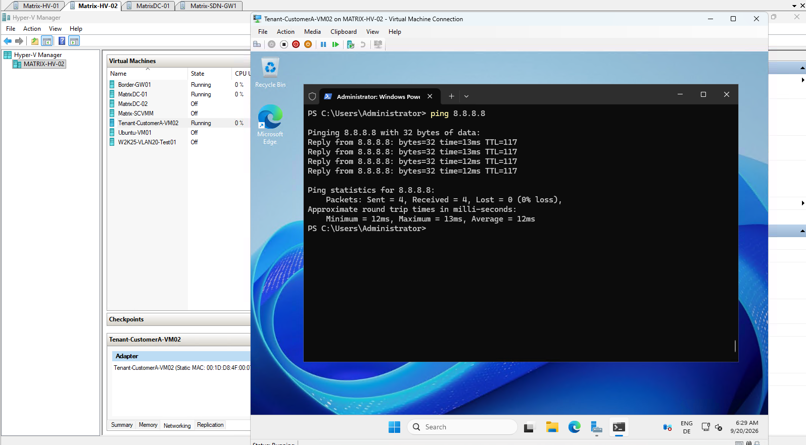
From Tenant-CustomerA-VM02 on Matrix-HV-02, we generate ICMP traffic to 8.8.8.8, confirming successful WAN connectivity through the SDN Gateway and pfSense. This traffic will now be captured directly inside Matrix-SDN-GW1 using Wireshark.
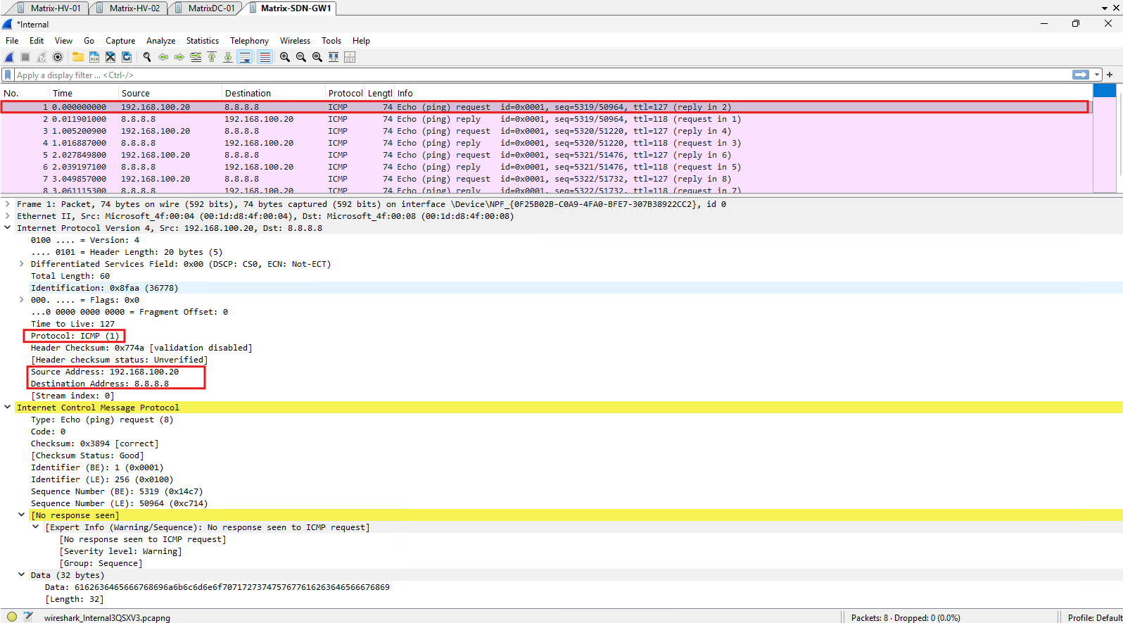
The capture shows the original tenant ICMP Echo Request from 192.168.100.20 to 8.8.8.8 as it passes through the SDN Gateway.
Because the gateway is routing the packet rather than performing NAT at this stage, the original source and destination IP addresses remain unchanged; only the Layer-2 forwarding information changes as the packet moves through the SDN datapath.
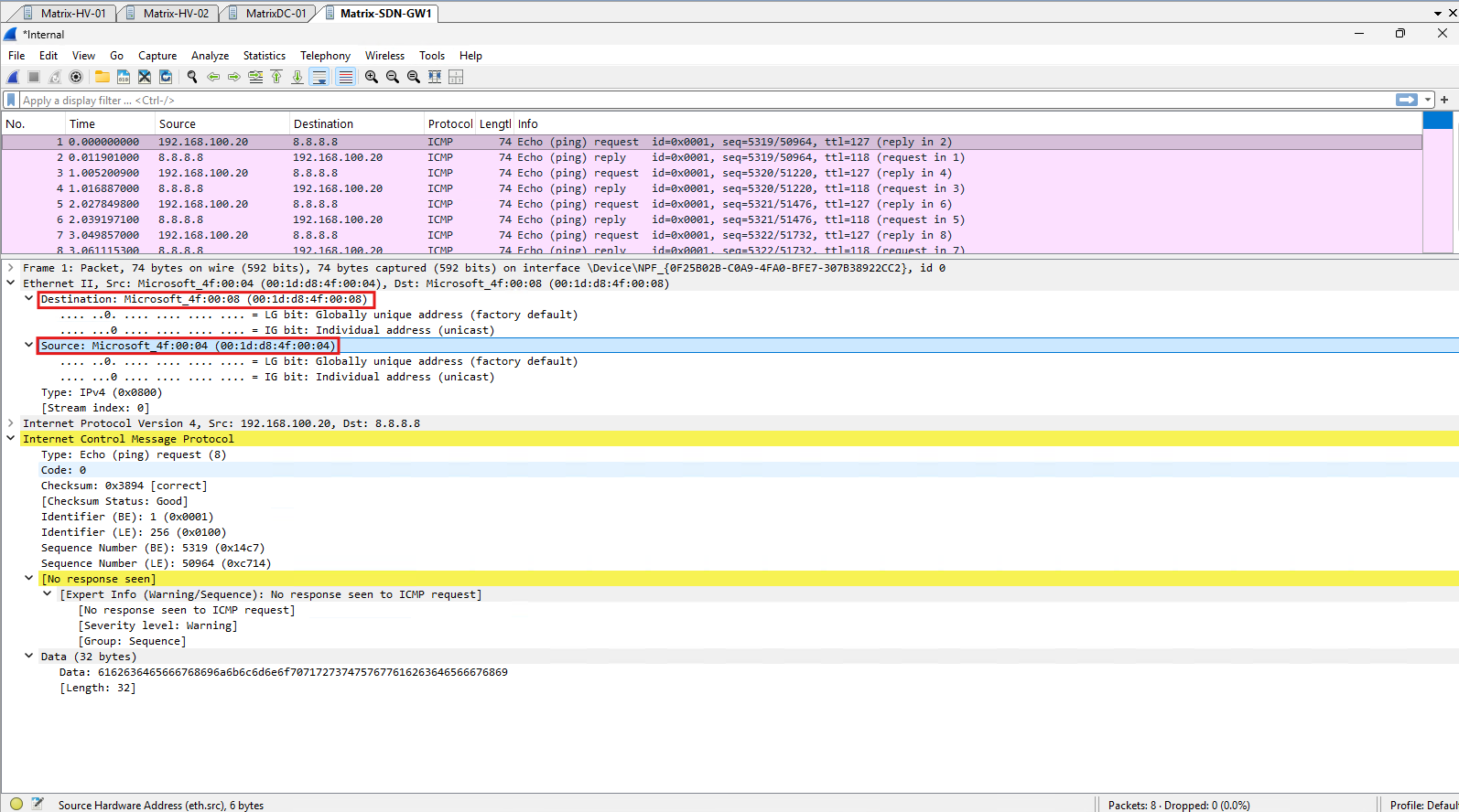
The capture inside Matrix-SDN-GW1 shows the original tenant packet (
192.168.100.20 → 8.8.8.8) arriving from the HNV virtual gateway MAC00:1D:D8:4F:00:04at the SDN Gateway’s Internal adapter00:1D:D8:4F:00:08. This demonstrates the handoff of the routed tenant traffic from the HNV fabric to the SDN Gateway while the original IP addresses remain unchanged.
This completes the packet trace from the HNV overlay through the SDN Gateway and onto the L3 transit network toward pfSense.
The captures demonstrate how the original tenant packet is preserved while the SDN fabric changes the underlying encapsulation and Layer-2 forwarding information at each stage of the path.
Troubleshooting
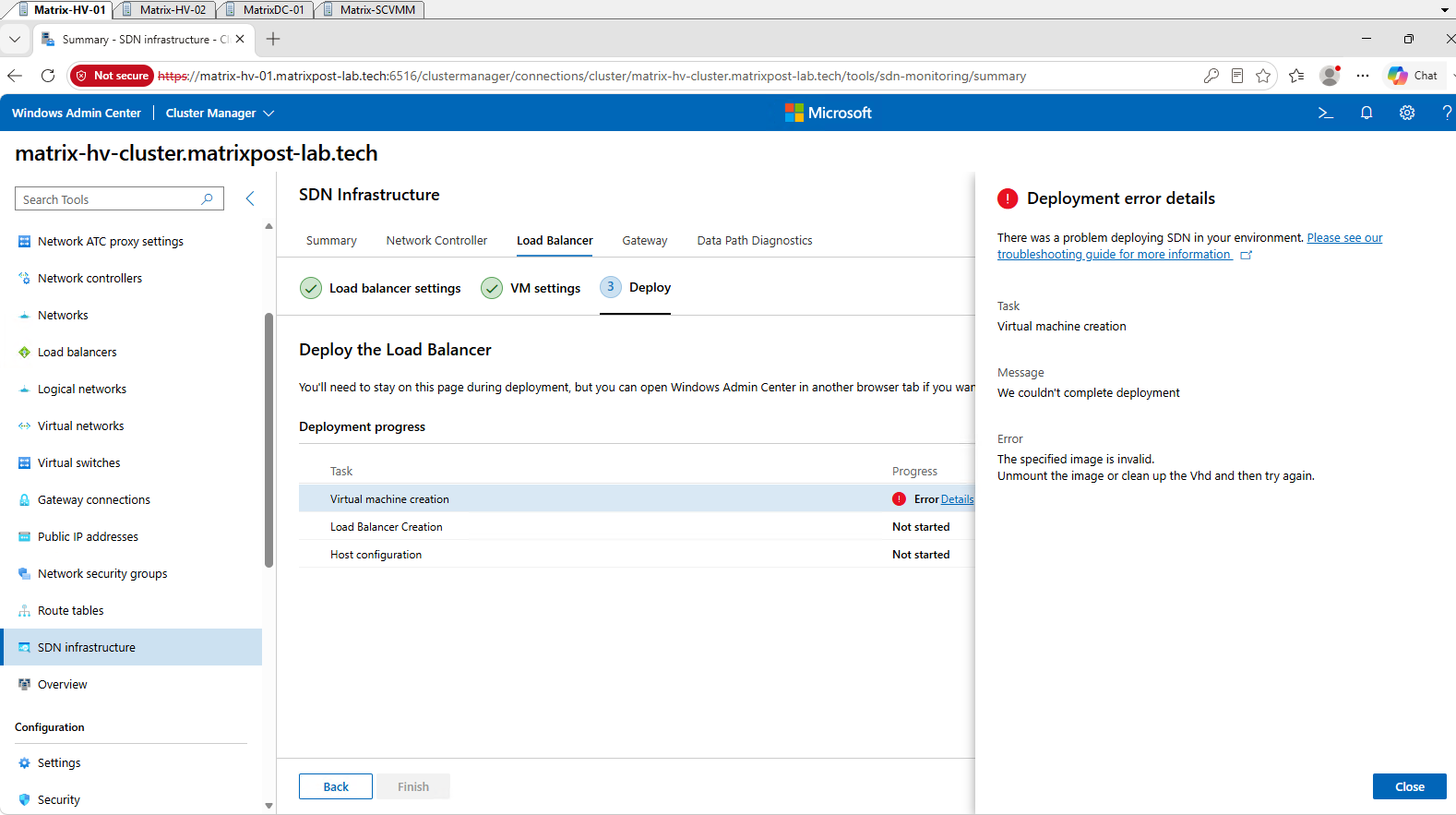
Mount-VHD "\\Matrix-SCVMM.matrixpost-lab.tech\MSSCVMMLibrary\VHDs\W2K25-Template.vhdx" -ReadOnly -Passthru | Get-Disk

Get-Partition -DiskNumber 2 | Get-Volume | Format-Table DriveLetter,FileSystemLabel,FileSystem,Size -AutoSize

reg load HKLM\OfflineSoftware E:\Windows\System32\Config\SOFTWARE
reg query "HKLM\OfflineSoftware\Microsoft\Windows NT\CurrentVersion" /v ProductName
reg query "HKLM\OfflineSoftware\Microsoft\Windows NT\CurrentVersion" /v EditionID
reg unload HKLM\OfflineSoftware
Links
Deploy SDN Gateway
https://learn.microsoft.com/en-us/previous-versions/azure/azure-local/deploy/sdn-wizard#deploy-sdn-gatewaySet up an SDN software load balancer (SLB) in the VMM fabric
https://learn.microsoft.com/en-us/system-center/vmm/sdn-slbDeploy and manage a Software Defined Network (SDN) infrastructure in the VMM fabric
https://learn.microsoft.com/en-us/system-center/vmm/deploy-sdnSet up an SDN network controller in the VMM fabric
https://learn.microsoft.com/en-us/system-center/vmm/sdn-controllerAdd a virtual gateway to a tenant virtual network
https://learn.microsoft.com/en-us/windows-server/networking/sdn/manage/add-a-virtual-gateway-to-a-tenant-virtual-networkAzure Virtual Filtering Platform (VFP)
https://www.microsoft.com/en-us/research/project/azure-virtual-filtering-platform/