Windows Server Software Defined Networking (SDN) and Hyper-V Network Virtualization (HNV) – Part 2: Testing Cross-Host HNV Connectivity
In Part 1 of this series, we deployed the fundamental Windows Server Software Defined Networking (SDN) infrastructure, including the Network Controller, configured the Provider Address (PA) network, integrated our Hyper-V hosts with the SDN infrastructure, and created our first isolated Hyper-V Network Virtualization (HNV) tenant network, Tenant-CustomerA.
So far, however, we have connected only a single tenant workload. In this second part, we will extend Tenant-CustomerA by deploying a second virtual machine on another Hyper-V host and connect it to the same HNV virtual network.
This allows us to examine how HNV provides cross-host tenant connectivity while keeping the tenant Customer Address (CA) network completely decoupled from the underlying physical network. We will also look at how the Network Controller assigns Provider Addresses (PAs) to the Hyper-V hosts as tenant workloads are deployed.
Finally, we will capture the traffic on the physical network with Wireshark and examine the resulting VXLAN encapsulation, showing how traffic between 192.168.100.0/24 tenant workloads is transported across the Provider Address network between our two Hyper-V hosts.
In Part 3, we will extend the tenant network beyond the HNV fabric using the native Microsoft SDN Gateway and pfSense.
In Part 4, we will introduce a second tenant with an overlapping IP address space, before using Linux VRFs (Virtual Routing and Forwarding) in Part 5 to preserve the separate tenant routing contexts beyond HNV while sharing the same Internet connection.
In Part 6, we will extend the overlapping tenant networks even further by connecting each HNV tenant to a separate Azure Virtual Network (VNet) through its own Site-to-Site IPsec VPN, using XFRM interfaces and Linux VRFs to preserve the individual tenant routing contexts. XFRM interfaces were introduced to overcome design limitations of the existing Linux VTI devices and provide a more flexible interface-based approach for IPsec processing.
Deploying a Second Tenant VM on Another Hyper-V Host
To demonstrate how Hyper-V Network Virtualization (HNV) transports tenant traffic between different physical Hyper-V hosts, we will now deploy a second VM in the existing Tenant-CustomerA virtual network. While Tenant-CustomerA-VM01 runs on Matrix-HV-01, the new Tenant-CustomerA-VM02 will be placed on Matrix-HV-02.
Both VMs will use Customer Addresses (CAs) from the same virtual subnet 192.168.100.0/24. Although the workloads are running on different Hyper-V hosts, HNV allows them to communicate as if they were connected to the same Layer-2 network.
Virtual Filtering Platform (VFP) on the Hyper-V hosts performs the required HNV processing, while the encapsulated traffic is transported between the hosts through the Provider Address (PA) network 10.0.30.0/24 on VLAN 30.
We begin by deploying a second tenant VM named Tenant-CustomerA-VM02 from the same Windows Server 2025 VM template used for the first tenant workload.
The VM will use the existing
Tenant-CustomerAHNV virtual network but will be deliberately placed onMatrix-HV-02, allowing us to demonstrate HNV communication between workloads running on different physical Hyper-V hosts.
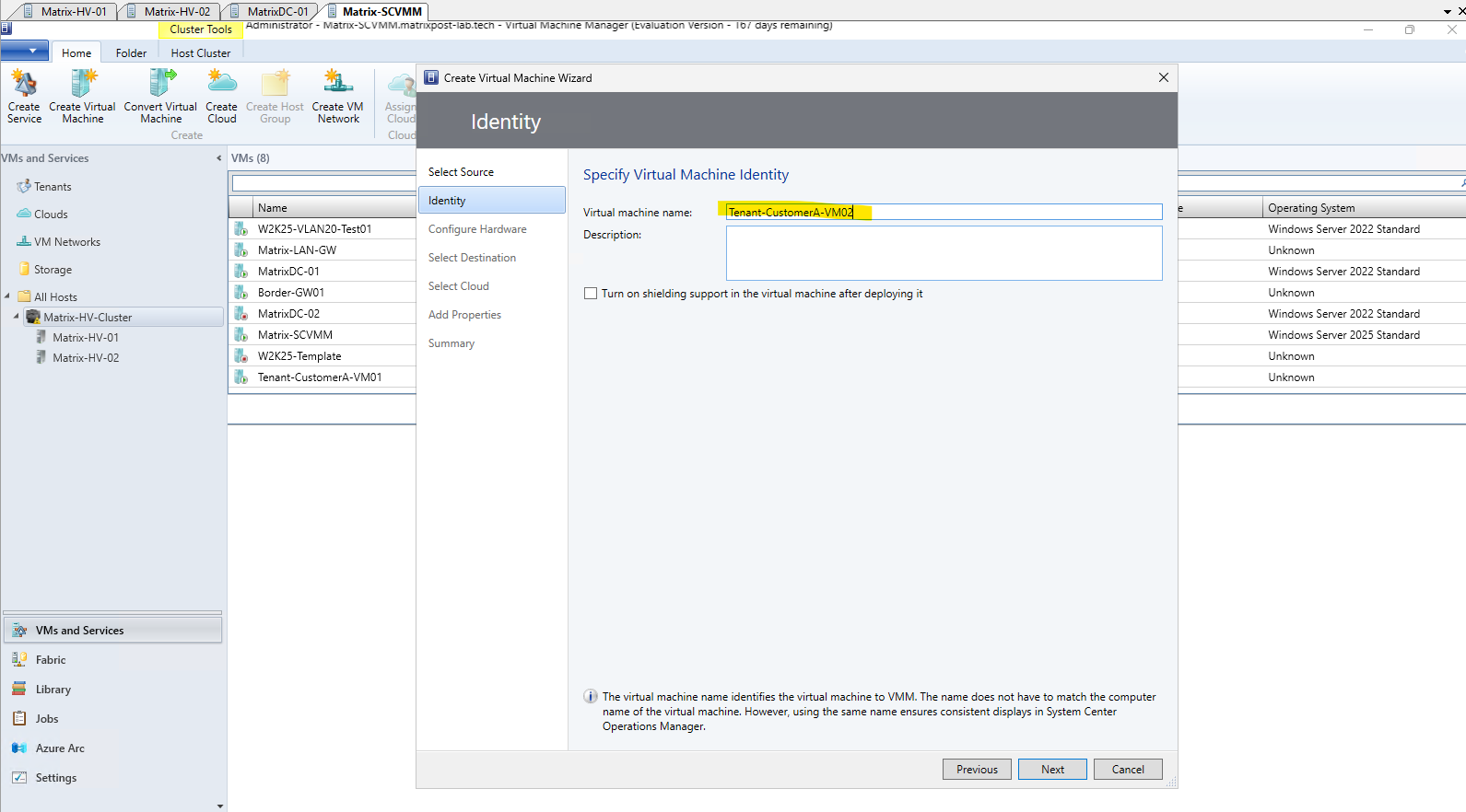
To demonstrate cross-host HNV communication, Tenant-CustomerA-VM02 is deliberately placed on Matrix-HV-02, while the first tenant VM Tenant-CustomerA-VM01 remains on Matrix-HV-01.
This ensures that communication between the two tenant VMs must traverse the physical network using the HNV Provider Address (PA) network, rather than remaining local to a single Hyper-V host.
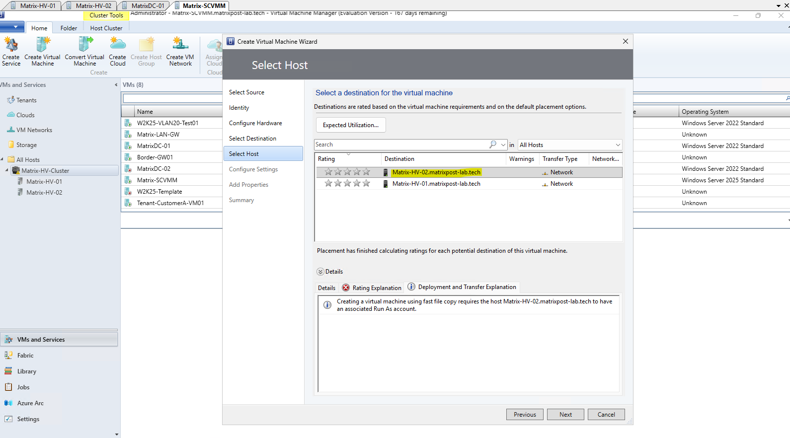
During the initial deployment, the network adapter of Tenant-CustomerA-VM02 is again left not connected. The HNV configuration will be applied after deployment by assigning a static MAC address, connecting the adapter to vSwitch-VM, creating the corresponding Network Controller network interface, and finally binding its Network Controller port profile to the Hyper-V VM network adapter.
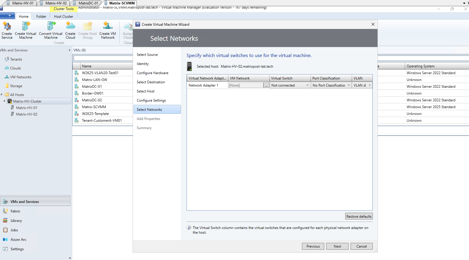
The deployment summary confirms that Tenant-CustomerA-VM02 will be created on Matrix-HV-02 and stored on the cluster shared storage. As with the first tenant VM, the VM is initially left powered off, allowing us to configure its static MAC address and complete the required Network Controller/HNV configuration before starting the workload.
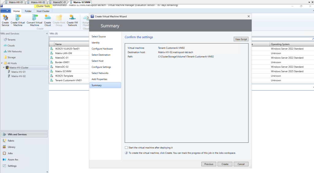
The deployment is running now on Matrix-HV-02.
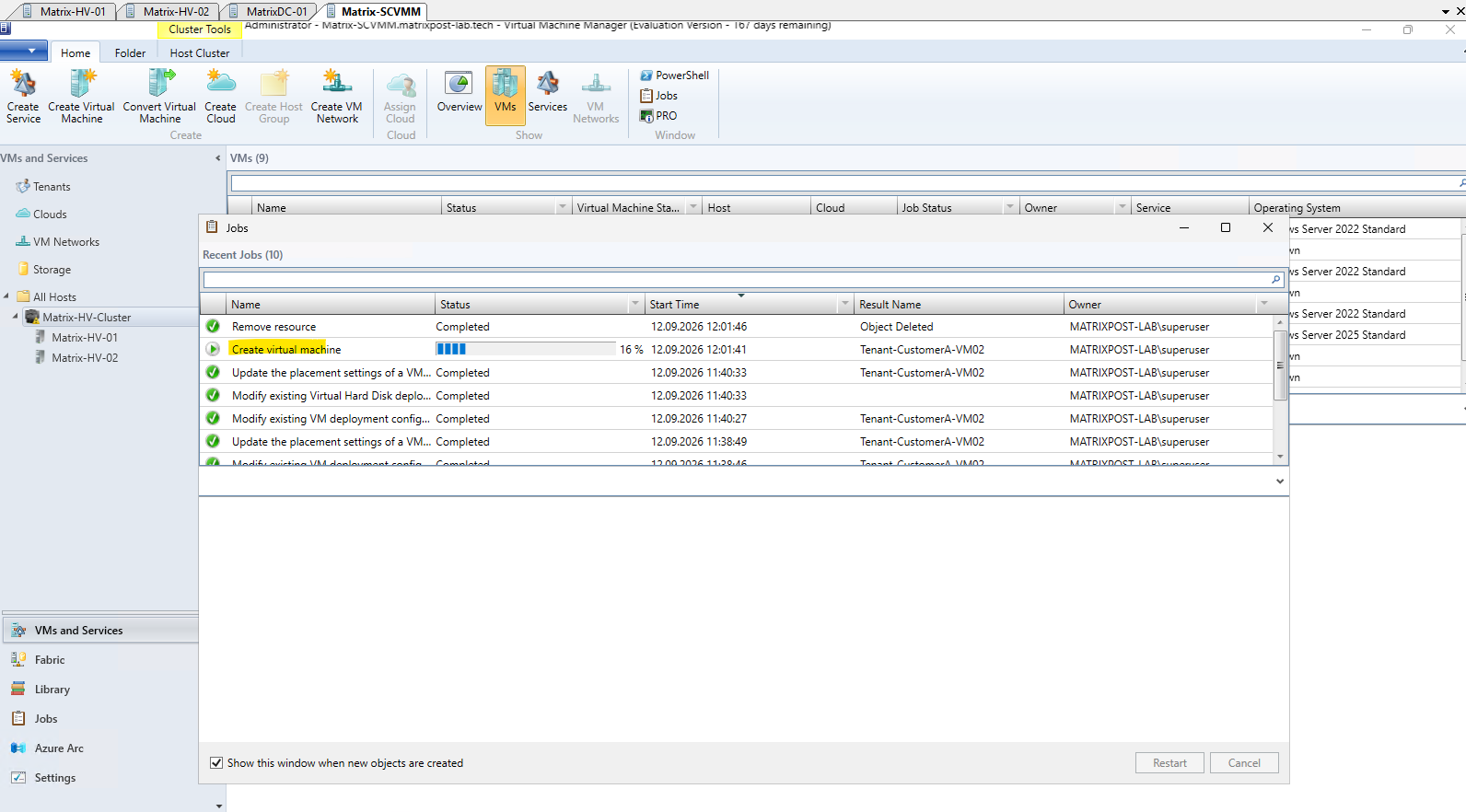
The successful deployment confirms that Tenant-CustomerA-VM02 has been created on Matrix-HV-02 and remains powered off, ready for the static MAC address and subsequent Network Controller/HNV configuration.

Connecting the Second Tenant VM to the HNV Virtual Network Using Windows Admin Center
For the first tenant VM, we deliberately used native PowerShell to configure the individual SDN components and understand what happens behind the scenes when connecting a VM to an HNV virtual network.
Now that we have seen these underlying configuration steps in detail, we will take a different approach for the second tenant VM and use the built-in SDN management capabilities of Windows Admin Center (WAC) to connect it to the existing HNV virtual network.
Note: Windows Admin Center (WAC) can be installed directly on one of the Hyper-V hosts using the Windows Admin Center installer. When installing WAC on a Hyper-V host, use the custom setup to select a different HTTPS port if the default TCP port 443 is already in use; in this lab, WAC is therefore accessed through a dedicated HTTPS port e.g. 6516.
Connecting the VM Network Adapter
In Windows Admin Center, open the matrix-hv-cluster.matrixpost-lab.tech cluster and navigate to Virtual networks. The existing Tenant-CustomerA virtual network is shown as Healthy and currently has one virtual machine connection, representing Tenant-VM01.
From the Windows Admin Center home page, we connect to the matrix-hv-cluster.matrixpost-lab.tech failover cluster. Managing the cluster connection rather than an individual Hyper-V host provides access to the integrated SDN management tools for the entire cluster.
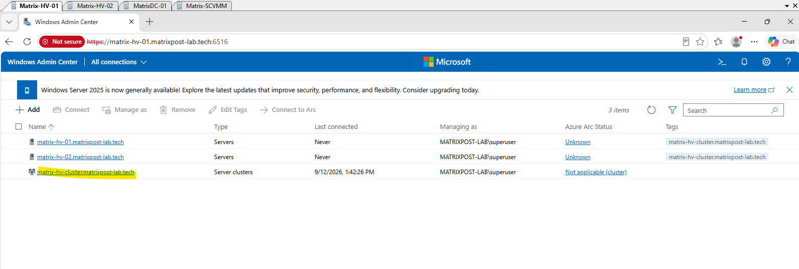
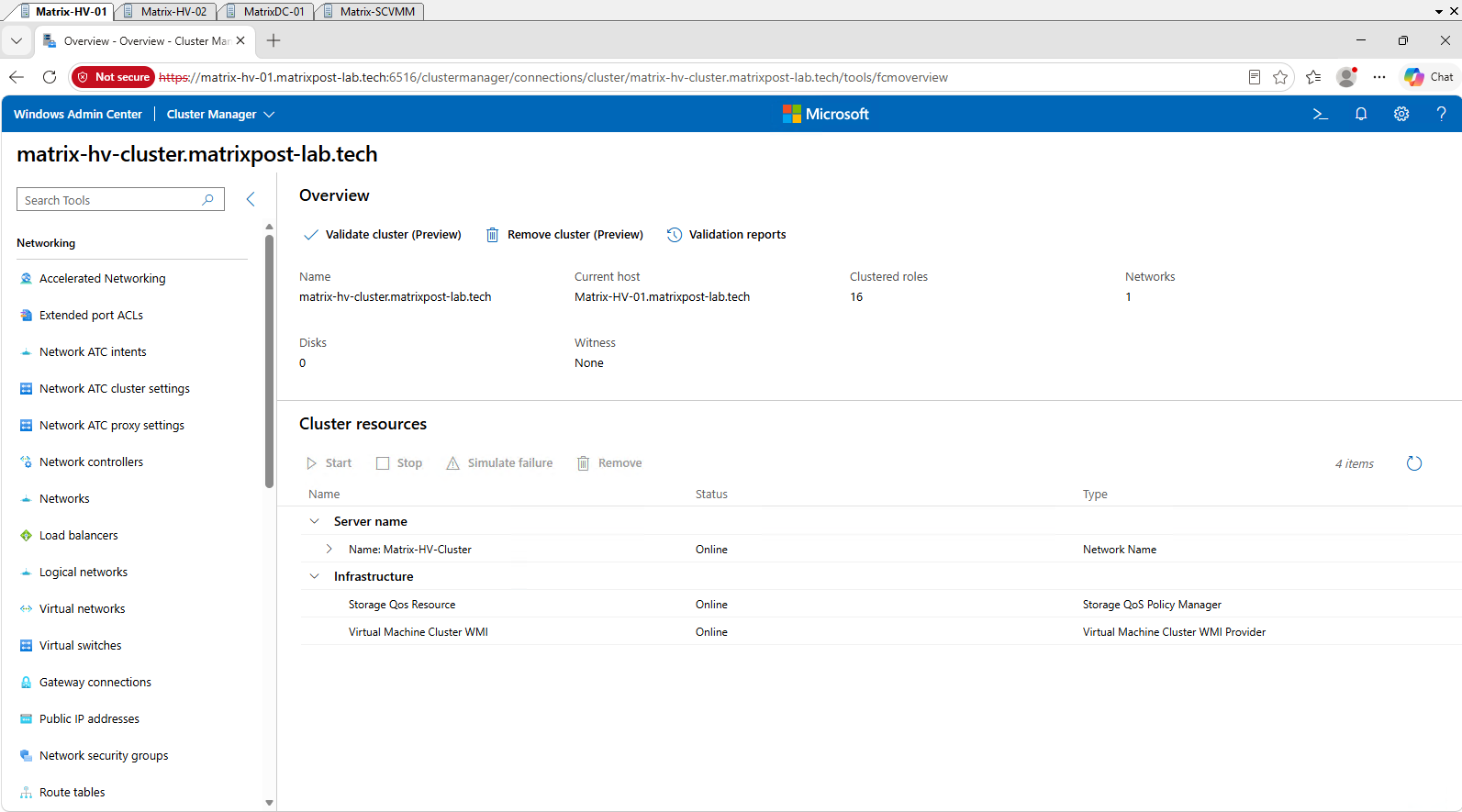
After connecting to the failover cluster, Windows Admin Center opens the Cluster Manager, which provides access to the cluster-wide networking and SDN management tools.
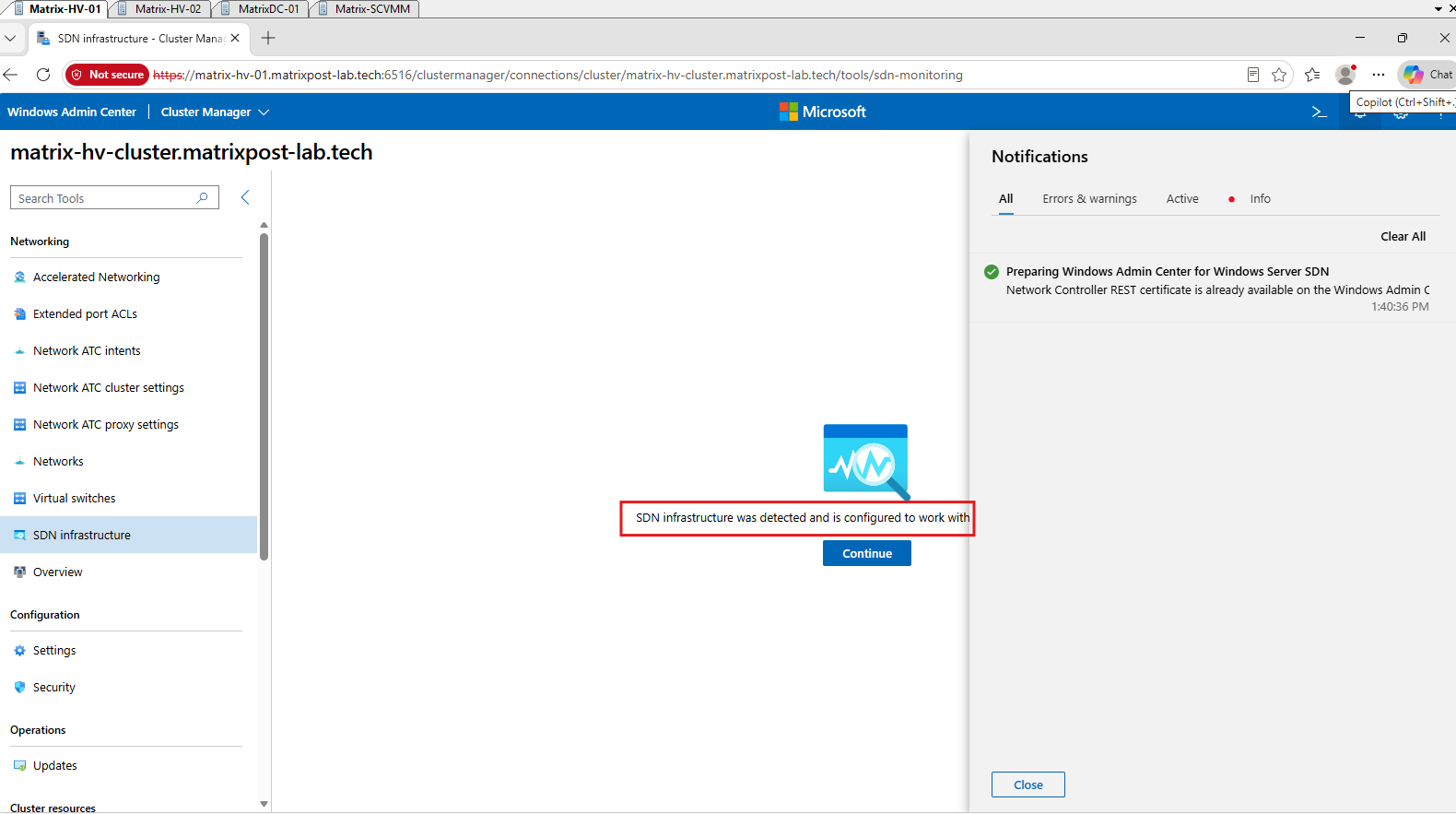
The first time the SDN management tools are opened, Windows Admin Center automatically detects the existing Software Defined Networking (SDN) infrastructure and prepares itself for managing it. In our environment, WAC also detects that the Network Controller REST certificate is already available, so no additional certificate configuration is required.
Before configuring the second tenant VM, we can use the SDN Infrastructure dashboard in Windows Admin Center to verify the overall health of the deployed SDN environment.
In our lab, both Hyper-V servers are reported as Healthy, while no Software Load Balancer (SLB) MUX or SDN Gateway infrastructure is currently deployed.
An SDN Gateway provides connectivity between HNV tenant virtual networks and external networks and is managed by the Network Controller. After connecting our second tenant VM, we will deploy an SDN Gateway to extend our tenant network beyond the HNV overlay.
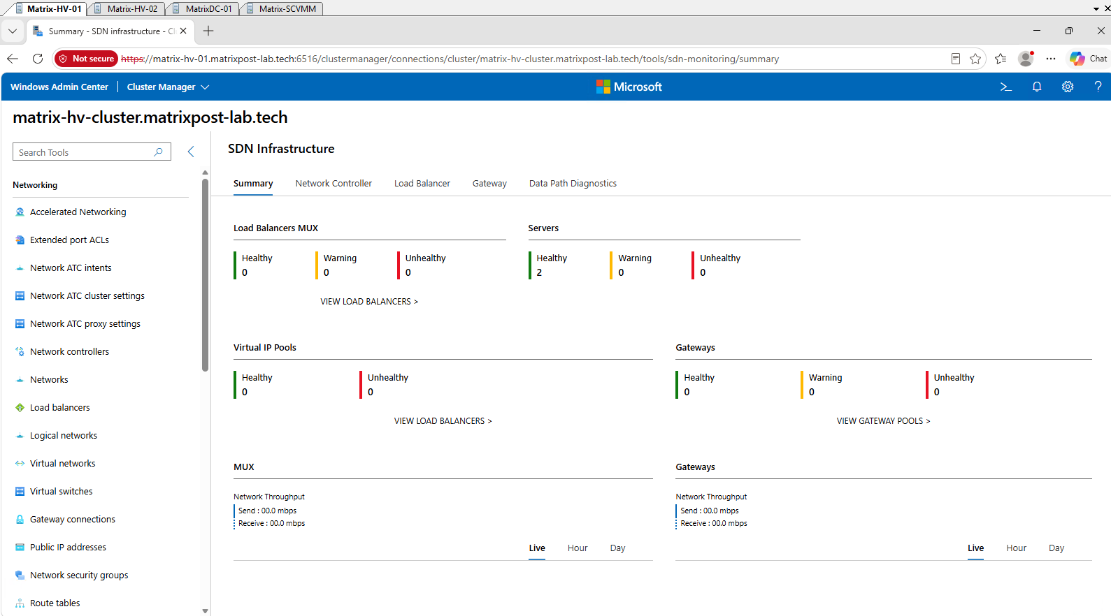
We can now connect the network adapter of Tenant-VM02 to the existing Tenant-CustomerA HNV virtual network. Unlike with the first tenant VM, we will perform the complete network adapter configuration through Windows Admin Center, which handles the required integration with the Network Controller for us.
To connect the network adapter of Tenant-CustomerA-VM02 to our existing HNV virtual network, navigate to Cluster resources → Virtual machines in Windows Admin Center and select our second tenant VM Tenant-CustomerA-VM02.
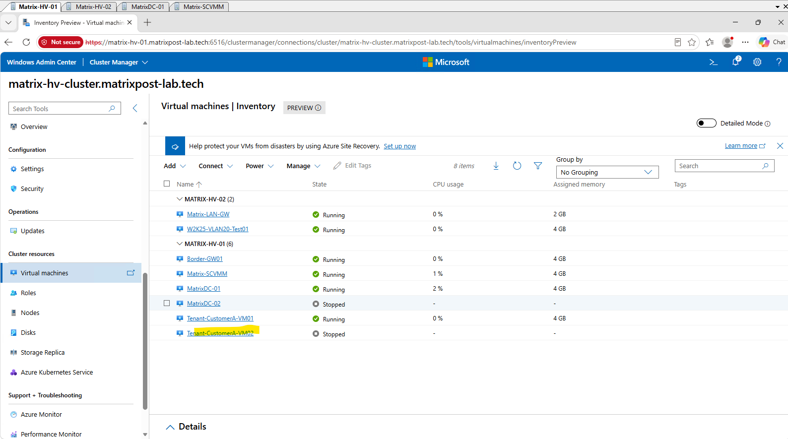
With the Tenant-CustomerA-VM02 details open, click Settings to access the virtual machine configuration.
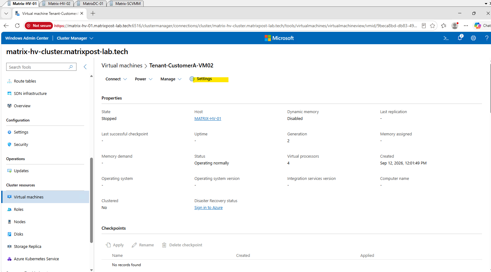
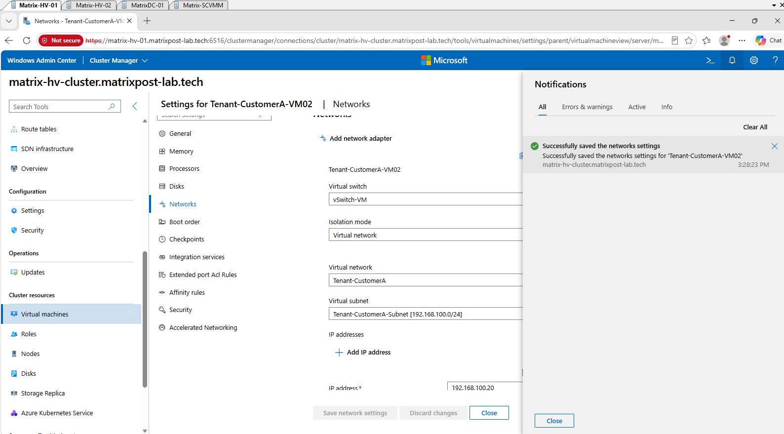
In the VM settings, select Networks and connect the network adapter to the vSwitch-VM virtual switch.
This is the SDN-enabled Hyper-V virtual switch that provides the underlying connectivity required before the adapter can be associated with an HNV virtual network.
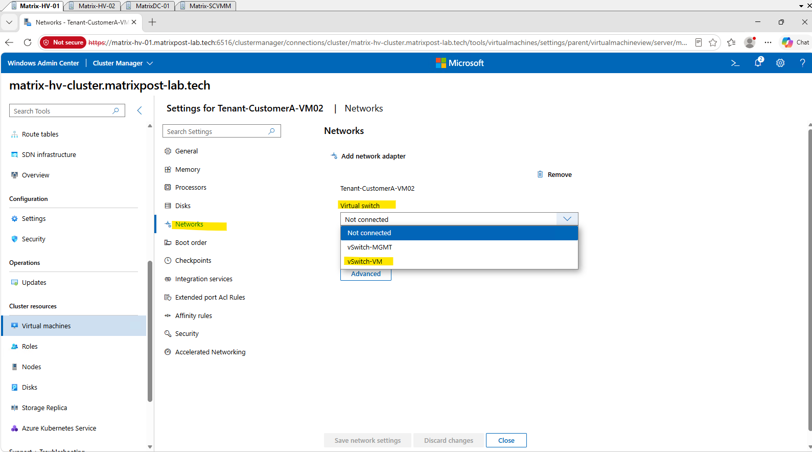
Once vSwitch-VM is selected, Windows Admin Center automatically exposes the additional Isolation mode options. Select Virtual network to configure the VM network adapter for HNV-based network virtualization instead of traditional VLAN isolation or a logical network.
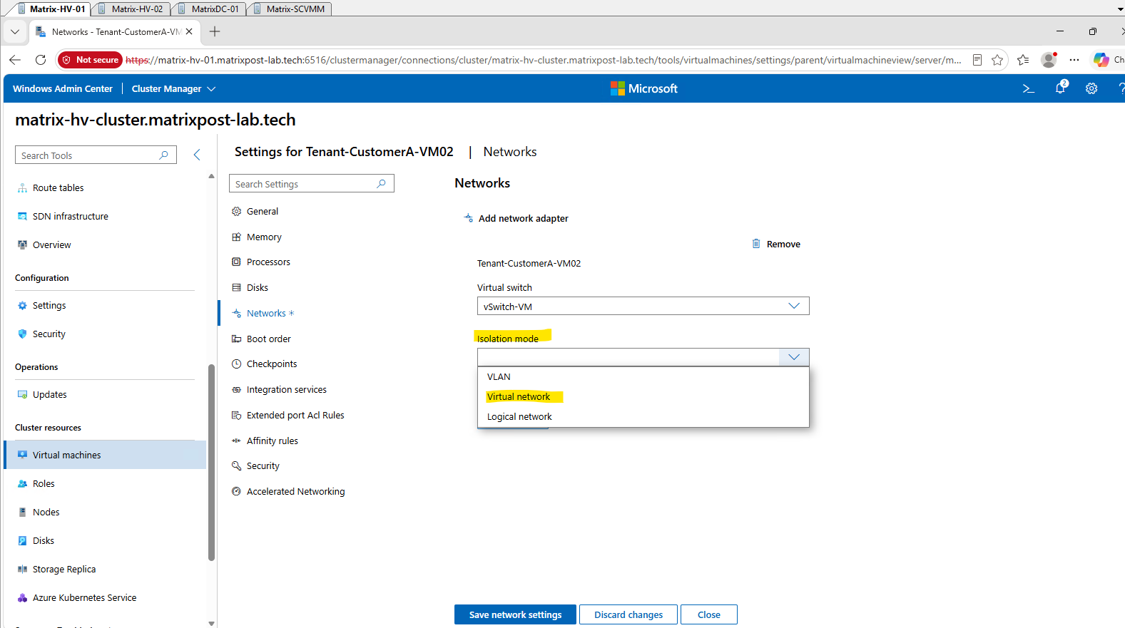
After selecting Virtual network as the isolation mode, Windows Admin Center displays the HNV virtual networks available through the Network Controller. Select our existing Tenant-CustomerA virtual network.
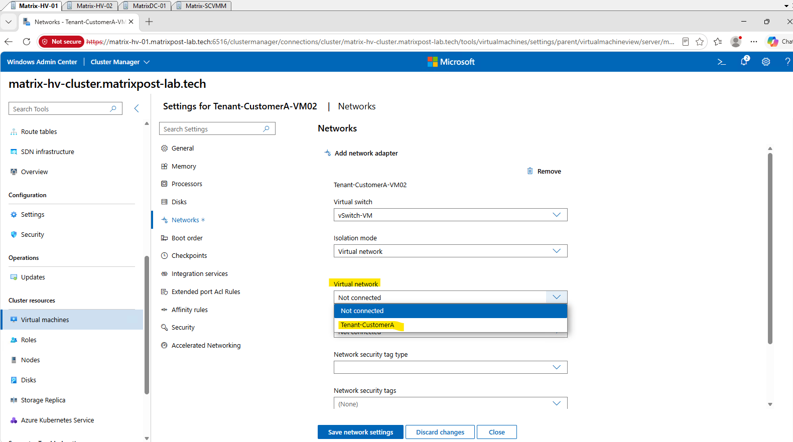
After selecting the Tenant-CustomerA virtual network, select Tenant-CustomerA-Subnet [192.168.100.0/24] as the Virtual subnet. This connects the VM network adapter to the same HNV tenant subnet already used by our first tenant VM.
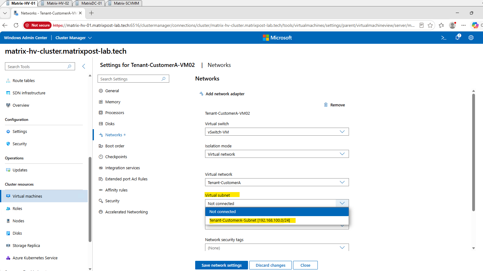
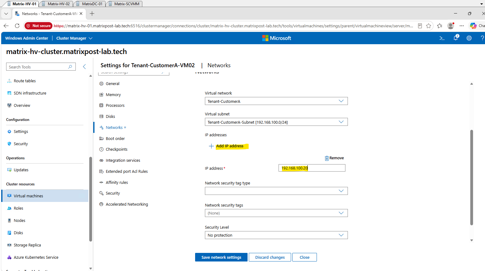
Click Add IP address and assign 192.168.100.20 to the second tenant VM.
We leave the optional network security tags and Security Level settings at their defaults, as they are not required for our basic HNV connectivity test.
Finally, click Save network settings to apply the configuration.
Windows Admin Center provides an Azure-like management experience for Windows Server SDN, including centralized resource views and asynchronous operation notifications.
After saving the configuration, WAC confirms that the network settings for Tenant-CustomerA-VM02 were successfully applied.
Starting the Second Tenant VM and Verifying Provider Address Allocation
With the second tenant VM connected to the Tenant-CustomerA HNV virtual network, we can now start the VM and verify that the Network Controller allocates a Provider Address (PA) for its network adapter.
Select Tenant-CustomerA-VM02 and choose Power → Start.
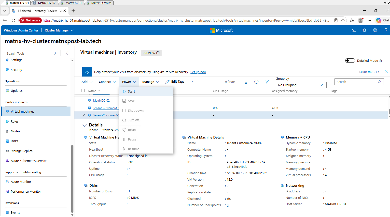
Tenant-CustomerA-VM02 is now running on MATRIX-HV-01 and Windows is starting. Although the VM was originally deployed on MATRIX-HV-02, its cluster placement has changed in the meantime.
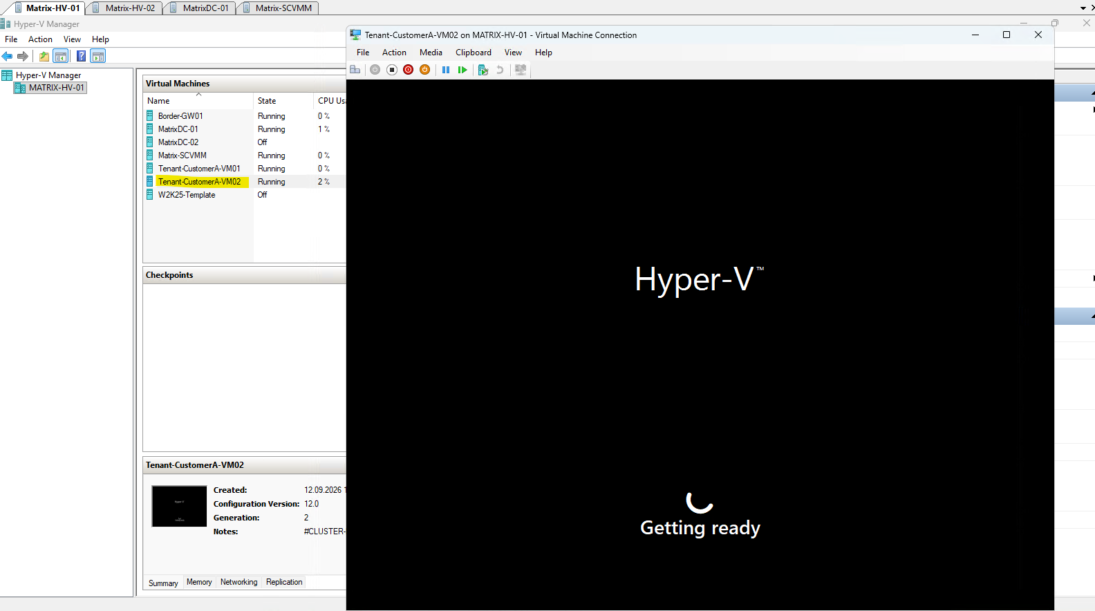
Since the VM was deployed from our Sysprep-prepared Windows Server template, Windows starts with the initial Out-of-Box Experience (OOBE) to complete the operating system setup.
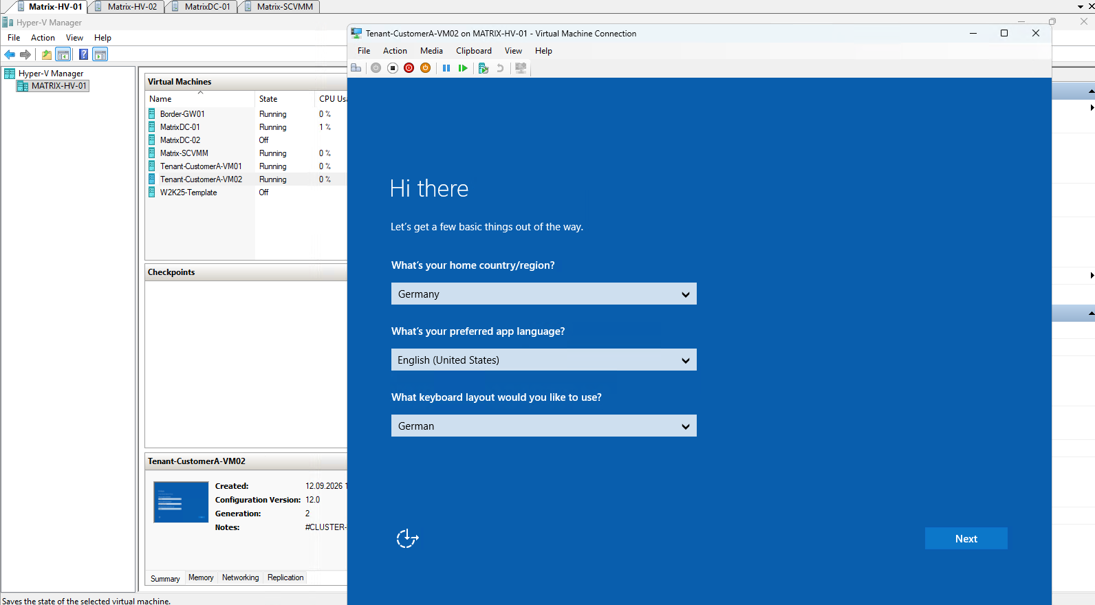
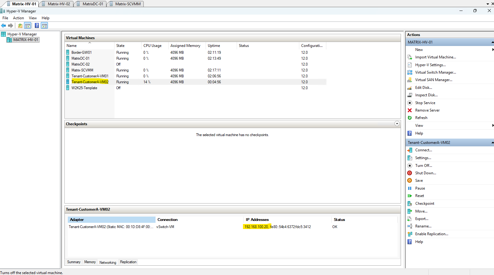
After completing the initial Windows setup, Hyper-V Manager shows
192.168.100.20for the network adapter of Tenant-CustomerA-VM02, confirming the tenant IP address configured through Windows Admin Center.
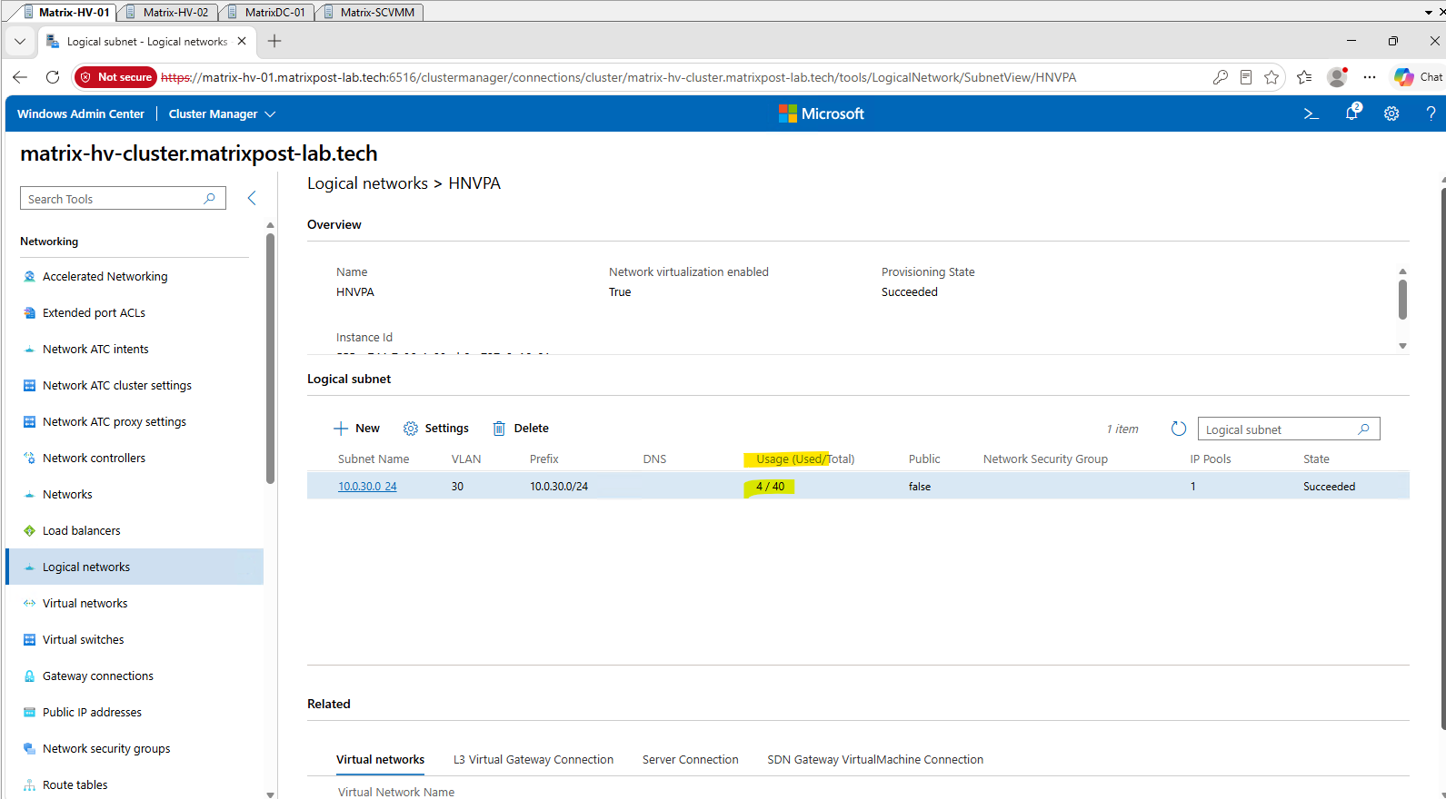
Windows Admin Center shows that the HNV Provider Address (PA) network 10.0.30.0/24 currently has 4 of 40 available addresses allocated.
These Provider Addresses are used by the Hyper-V hosts as the underlay addresses for transporting encapsulated HNV tenant traffic across the physical network.
While WAC provides a convenient overview of the PA address utilization, it does not expose the individual PA-to-host mappings in this view.
To identify the individual Provider Addresses (PAs) and their corresponding Hyper-V hosts, we use Invoke-Command to run Get-ProviderAddress remotely on both cluster nodes.
This provides a consolidated view of all PA addresses currently allocated across the Hyper-V cluster.
After creating the second HNV workload VM, we can see that the second Hyper-V host has also allocated a pair of PAs, resulting in four Provider Addresses across the cluster.
Invoke-Command -ComputerName Matrix-HV-01,Matrix-HV-02 -ScriptBlock { Get-ProviderAddress } | Format-Table PSComputerName,Address,MacAddress,PrefixLength,DefaultGateway,VlanID -AutoSize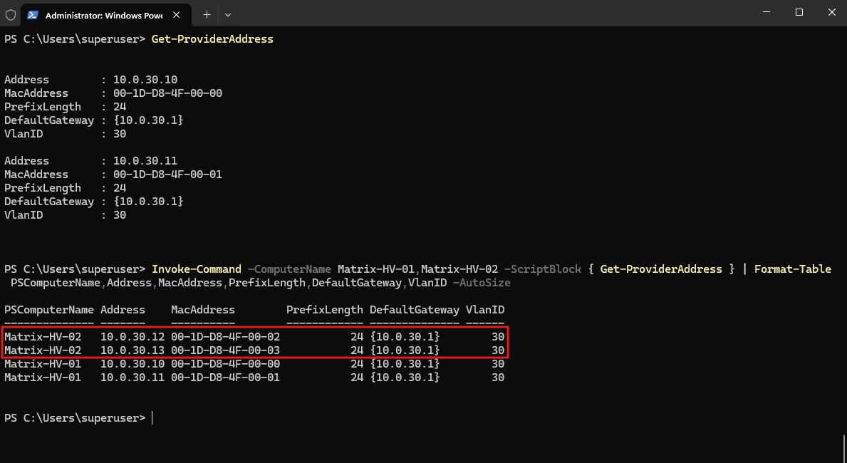
With the second HNV workload VM deployed and the Provider Address allocation verified, we can now test whether both tenant workloads can communicate across the HNV network.
In the next section, we will validate cross-host HNV tenant connectivity between the two Hyper-V hosts.
Testing Cross-Host HNV Tenant Connectivity
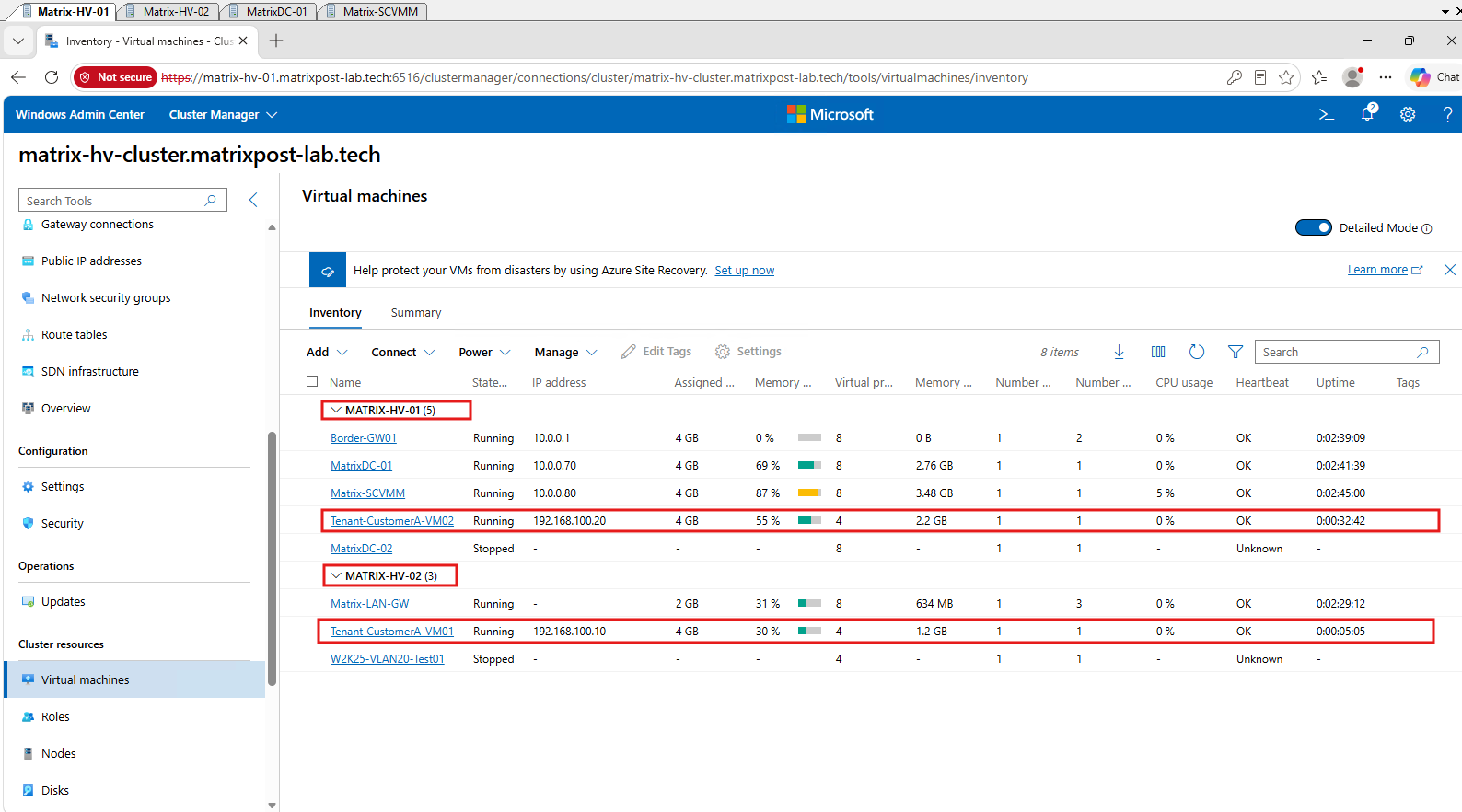
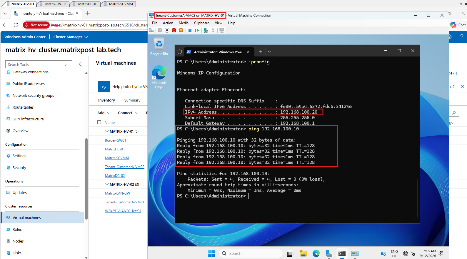
Before testing connectivity, we verify in Windows Admin Center that the two HNV tenant workloads are running on different Hyper-V hosts.
Tenant-CustomerA-VM02 is running on MATRIX-HV-01, while Tenant-CustomerA-VM01 is running on MATRIX-HV-02, ensuring that our following connectivity test traverses the HNV network between the two hosts.
Before testing connectivity with ICMP Echo Requests (ping), ensure that the local Windows Defender Firewall on both tenant VMs either allows inbound ICMP Echo Requests or is temporarily disabled for the test.
We can then ping Tenant-CustomerA-VM01 (192.168.100.10) from Tenant-CustomerA-VM02 (192.168.100.20).
The successful replies with 0% packet loss confirm that the two tenant workloads can communicate across the HNV virtual network, even though they are running on different Hyper-V hosts.
Capturing and Inspecting HNV Encapsulated Traffic with Wireshark
To see what happens on the physical network during cross-host HNV communication, we can capture the traffic on one of the Hyper-V hosts using Wireshark.
HNV encapsulation provides network virtualization and isolation but does not encrypt the traffic, allowing us to inspect both the outer Provider Address (PA) transport and the encapsulated Customer Address (CA) traffic.
By capturing a ping between our two tenant VMs, we should be able to observe how traffic between 192.168.100.20 and 192.168.100.10 is encapsulated and transported between the corresponding 10.0.30.x Provider Addresses.
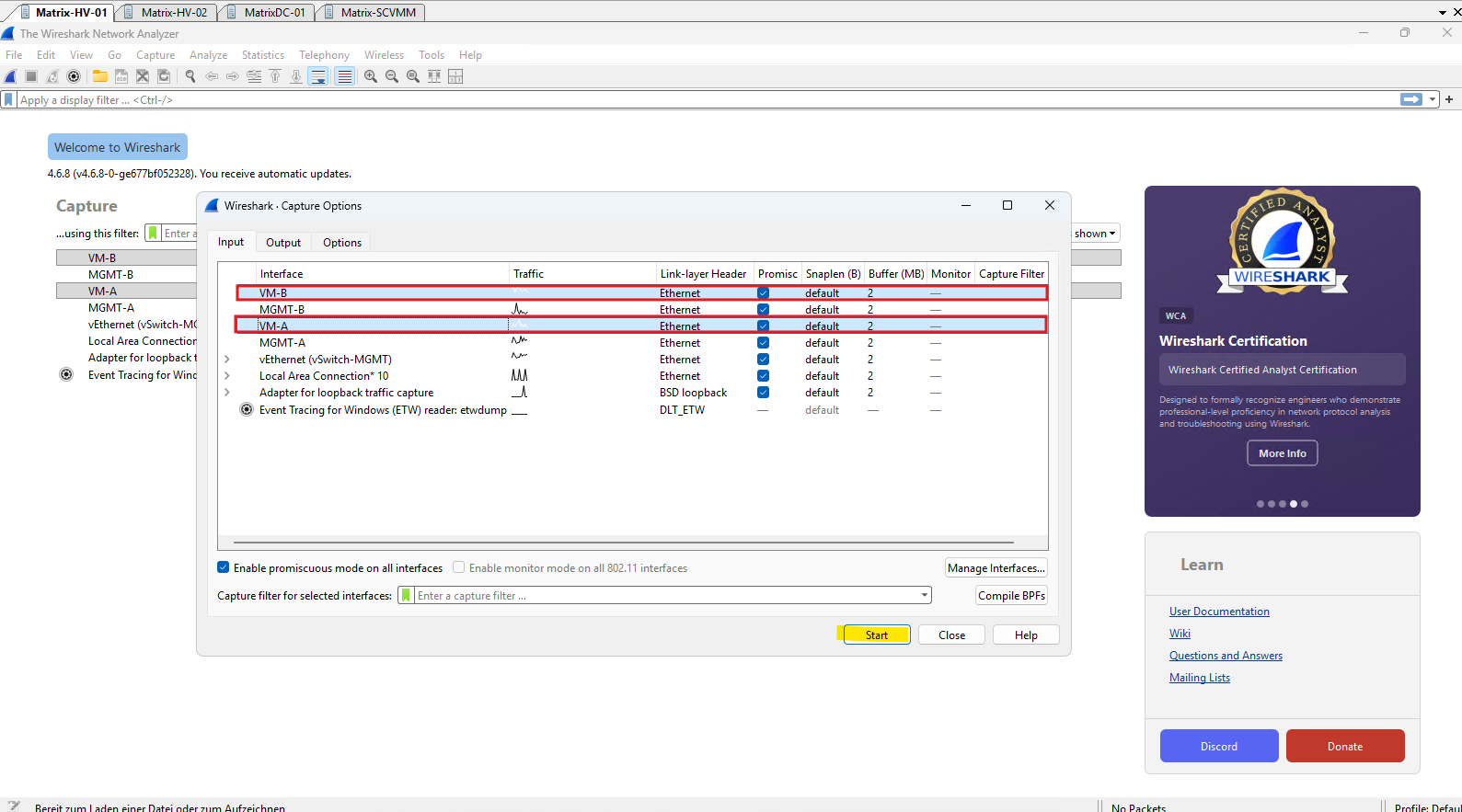
The vSwitch-VM Hyper-V virtual switch is configured as a Switch Embedded Teaming (SET) switch using the two physical network adapters VM-A and VM-B as its underlying uplinks.
Therefore, we select both physical SET adapters in Wireshark to capture the HNV traffic regardless of which uplink SET chooses for the flow.
The Wireshark capture clearly shows how HNV transports the tenant packet across the physical network using VXLAN encapsulation.
The original ICMP Echo Request from Customer Address (CA) 192.168.100.20 to 192.168.100.10 remains visible as the inner packet, while HNV encapsulates it inside VXLAN and transports it between the Provider Addresses (PA) 10.0.30.10 and 10.0.30.12.
The VXLAN Network Identifier (VNI)
4096uniquely identifies the HNV virtual subnet carrying this traffic. This identifier allows HNV to keep tenant overlay traffic logically isolated while transporting it across the same shared Provider Address (PA) underlay network.
Display filter ==> vxlan
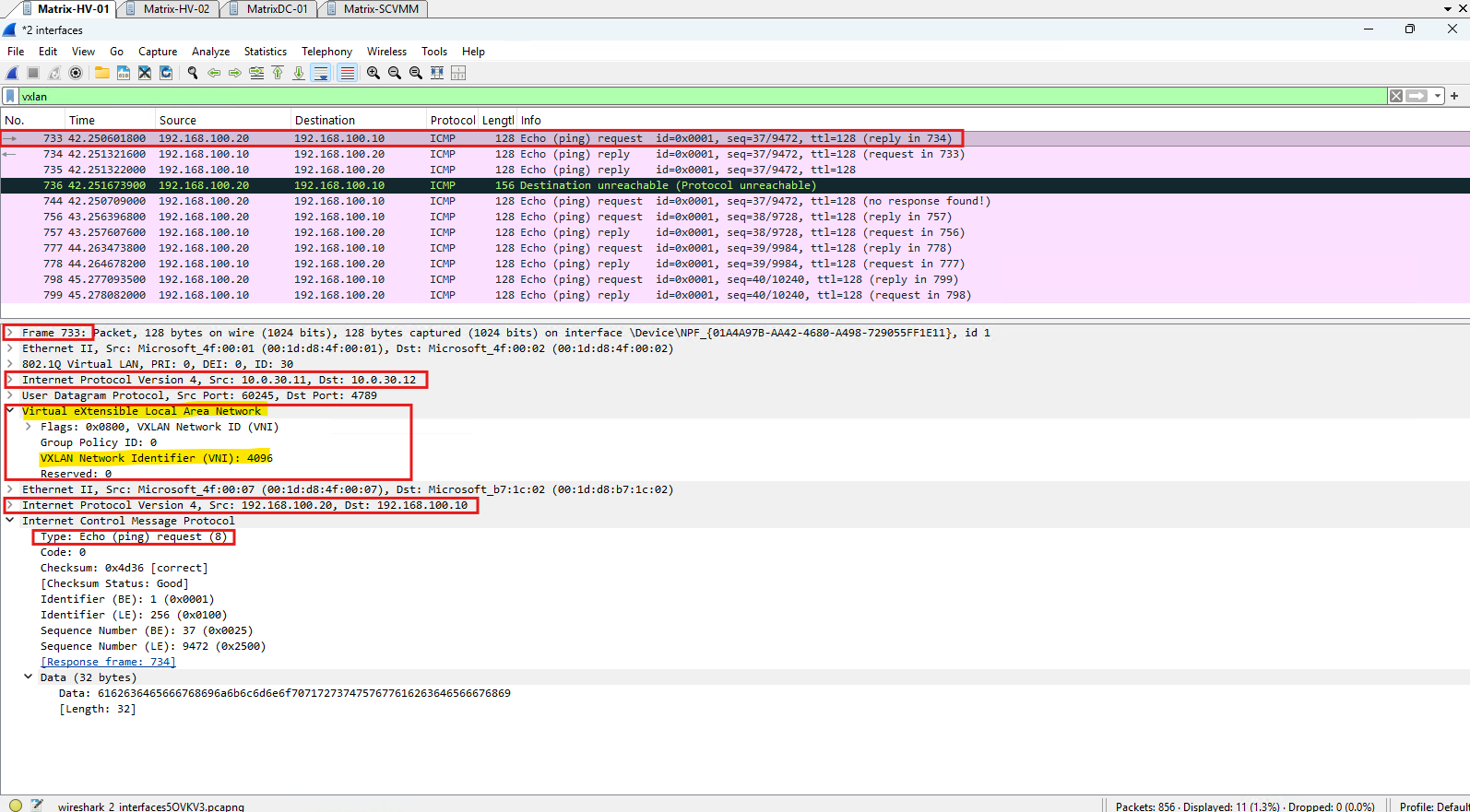
Reading the packet from the outside to the inside above, we can see the following encapsulation layers:
802.1Q VLAN 30 → Outer IPv4 (10.0.30.10 → 10.0.30.12) → UDP/4789 → VXLAN (VNI 4096) → Inner Ethernet → Inner IPv4 (192.168.100.20 → 192.168.100.10) → ICMP Echo Request
The outer IPv4 header belongs to the physical PA underlay and is used to transport the packet between the Hyper-V hosts, while the inner IPv4 header contains the original tenant CA addresses.
Because Virtual eXtensible LAN (VXLAN) provides encapsulation rather than encryption, Wireshark can inspect both the underlay and the original tenant packet.
Virtual eXtensible LAN (VXLAN)
Virtual eXtensible LAN (VXLAN) is the encapsulation technology used by HNV to create the tenant overlay network on top of the physical IP network. Instead of requiring the physical network to understand the tenant addresses, the original Ethernet frame is encapsulated inside a VXLAN header, transported using UDP port 4789, and then carried between the Hyper-V hosts using their Provider Addresses (PAs).
As shown already above, each VXLAN overlay is identified by a 24-bit VXLAN Network Identifier (VNI). In our capture, Wireshark shows VNI
4096, which identifies the virtual Layer-2 network to which the encapsulated tenant traffic belongs. The VNI therefore allows multiple isolated tenant networks to share the same physical underlay even when they use overlapping IP address spaces.
For our captured packet, the encapsulation can be visualized as:
Physical / Underlay Network
│
├─ 802.1Q VLAN 30
├─ Outer IPv4
│    10.0.30.10 → 10.0.30.12        Provider Addresses (PA)
├─ UDP
│    Destination Port 4789
├─ VXLAN
│    VNI 4096                        Overlay identification
│
└─ Encapsulated Tenant Frame
     ├─ Inner Ethernet
     ├─ Inner IPv4
     │    192.168.100.20 → 192.168.100.10   Customer Addresses (CA)
     └─ ICMP Echo Request
The physical network therefore only needs IP connectivity between the PA endpoints; it does not need routes for 192.168.100.0/24 or knowledge of the tenant virtual network.
HNV and the Network Controller manage the relationship between the tenant overlay and the PA underlay, while VXLAN provides the encapsulation used to carry the tenant frames between the Hyper-V hosts.
VXLAN is a standardized protocol defined by RFC 7348. It uses ordinary UDP/IP as its transport, typically UDP port 4789, to carry encapsulated Layer-2 Ethernet frames across an IP network.
Links
Hyper-V Network Virtualization Technical Details in Windows Server
https://learn.microsoft.com/en-us/windows-server/networking/sdn/technologies/hyper-v-network-virtualization/hyperv-network-virtualization-technical-details-windows-serverHyper-V Network Virtualization Overview in Windows Server
https://learn.microsoft.com/en-us/windows-server/networking/sdn/technologies/hyper-v-network-virtualization/hyperv-network-virtualization-overview-windows-serverUnderstand the usage of virtual networks and VLANs
https://learn.microsoft.com/en-us/windows-server/networking/sdn/manage/understanding-usage-of-virtual-networks-and-vlansSoftware and hardware (SH) integrated features and technologies
https://learn.microsoft.com/en-us/windows-server/networking/technologies/hpn/hpn-software-hardware-featuresAzure Virtual Filtering Platform (VFP)
https://www.microsoft.com/en-us/research/project/azure-virtual-filtering-platform/