Software Defined Networking (SDN) with VMware NSX – Part 3: Building Isolated Multi-Tenant Overlay Networks with Overlapping IP Addresses and Simultaneous WAN Access
In this Part 3 of our VMware NSX series, we will extend our existing SDN infrastructure to build isolated multi-tenant overlay networks using separate Tier-1 gateways, Tier-0 VRFs, and Linux VRFs for tenant-specific routing.
The main focus will be on configuring tenants with overlapping IP address spaces, including workloads using identical IP addresses, while maintaining complete network isolation. We will also configure and verify simultaneous Internet (WAN) access for both tenants through a shared Ubuntu router and WAN interface, using connection tracking, policy-based routing, and Source NAT (SNAT).
In Part 4 we take a look at troubleshooting commands that help us understand and diagnose our NSX environment. We will also compare connection tracking and stateful firewall behavior across platforms such as Linux, Juniper, Cisco, Check Point, Fortinet and pfSense.
- Configure the Network Infrastructure for TenantB
- Configure TenantB Workload Routing
- Configure the Default Route for the TenantB Linux VRF
- Verify Simultaneous TCP Connections from Overlapping Tenants
- Configure Tenant-Specific Linux Conntrack Zones
- Final Note – WAN Routers and Firewalls in Production Environments
- Links
Configure the Network Infrastructure for TenantB
In Part 2, we configured and verified Internet connectivity for TenantA through its NSX Tier-1 gateway, Tier-0 VRF, and our Ubuntu router.
We will now extend this configuration by adding a second tenant, TenantB, using the same 192.168.100.0/24 subnet as TenantA. Both tenants will also have a workload configured with the identical IP address 192.168.100.10.
To maintain network isolation, TenantB will receive its own NSX overlay segment, Tier-1 gateway, Tier-0 VRF, and dedicated Linux VRF on our Ubuntu router. Both tenants will share the existing physical VLAN trunk and WAN interface.
Our objective is to provide simultaneous Internet access for both tenants despite their overlapping IP addresses, without allowing traffic to cross between their isolated networks.
Create the Tier-0 VRF Gateway for TenantB
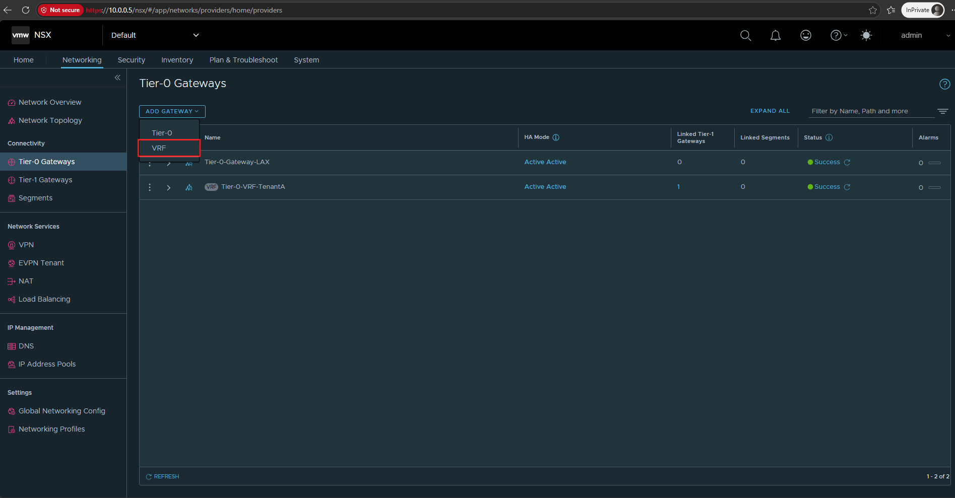
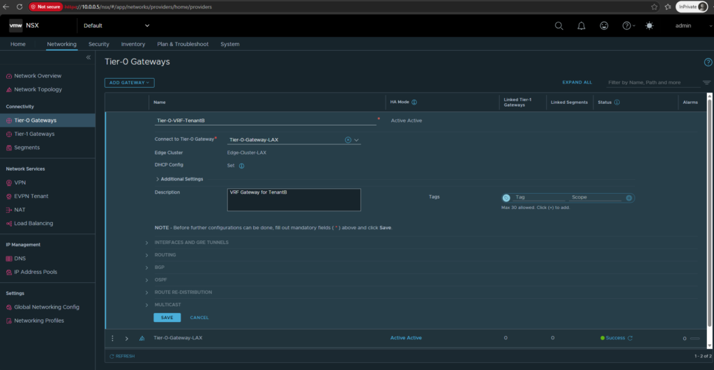
As with TenantA in Part 2, we create a dedicated Tier-0 VRF gateway for TenantB, named Tier-0-VRF-TenantB, using our existing parent gateway Tier-0-Gateway-LAX.
This provides TenantB with its own isolated routing instance, allowing both tenants to use overlapping IP address spaces while sharing the same NSX Edge infrastructure.
Click Add Gateway → VRF.
Create Tier-0-VRF-TenantB, selecting Tier-0-Gateway-LAX as its parent and using the description VRF Gateway for TenantB.
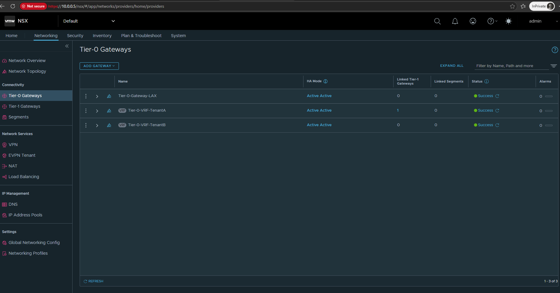
Tier-0-VRF-TenantB has been created successfully, alongside the existing TenantA VRF.
Create the VLAN Segment for TenantB
As described in Part 2, we use dedicated VLANs to connect each NSX Tier-0 VRF to its corresponding Linux VRF on our Ubuntu router.
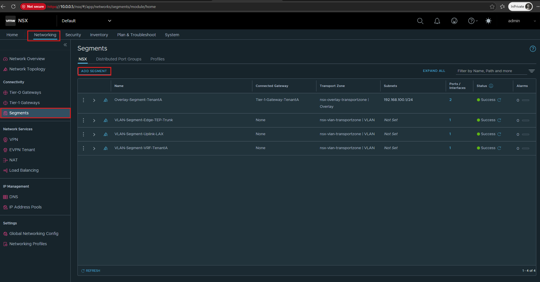
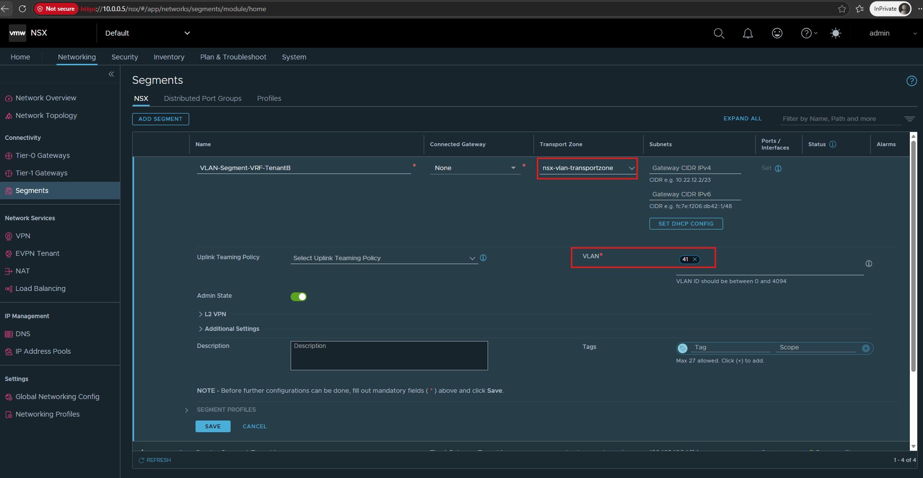
For TenantB, we create VLAN-Segment-VRF-TenantB using VLAN ID 41 and the transit network 10.0.41.0/30 in the existing NSX VLAN transport zone.
The NSX Tier-0 VRF will use 10.0.41.2, while our Ubuntu router will use 10.0.41.1 as the upstream next hop.
This provides the Layer-2 connection for TenantB’s external VRF handoff, while both tenants continue sharing the same physical VLAN trunk.
Navigate to Networking → Segments → Add Segment.
- Transport Zone:
nsx-vlan-transportzone - VLAN ID:
41 - Connected Gateway:
None - Gateway Subnet: Not configured
Click Save.
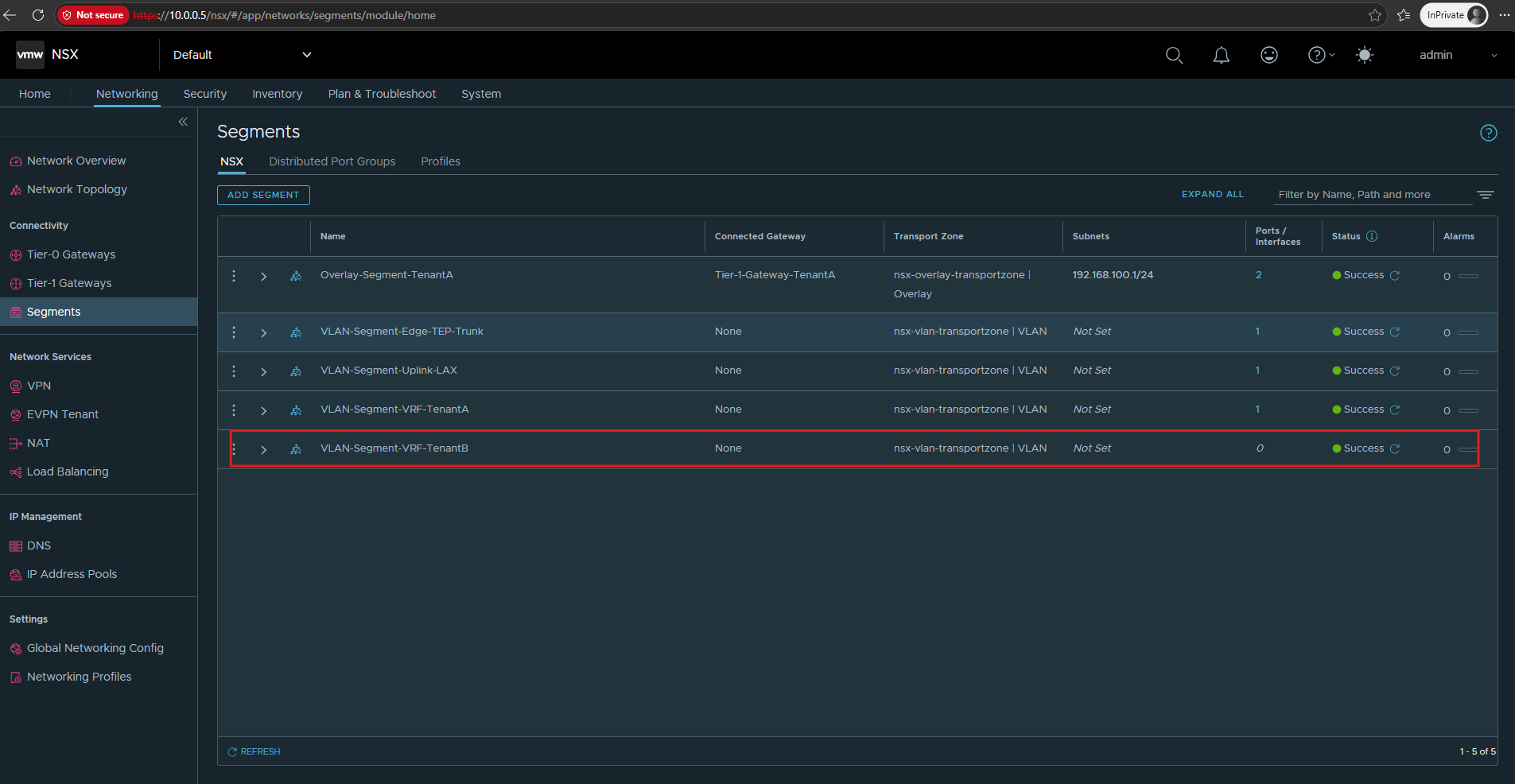
Configure the External Interface of the TenantB VRF Gateway.
Next, we configure the external interface of Tier-0-VRF-TenantB using our newly created VLAN-Segment-VRF-TenantB.
As with TenantA in Part 2, we use a dedicated /30 transit network for the connection to our Ubuntu router.
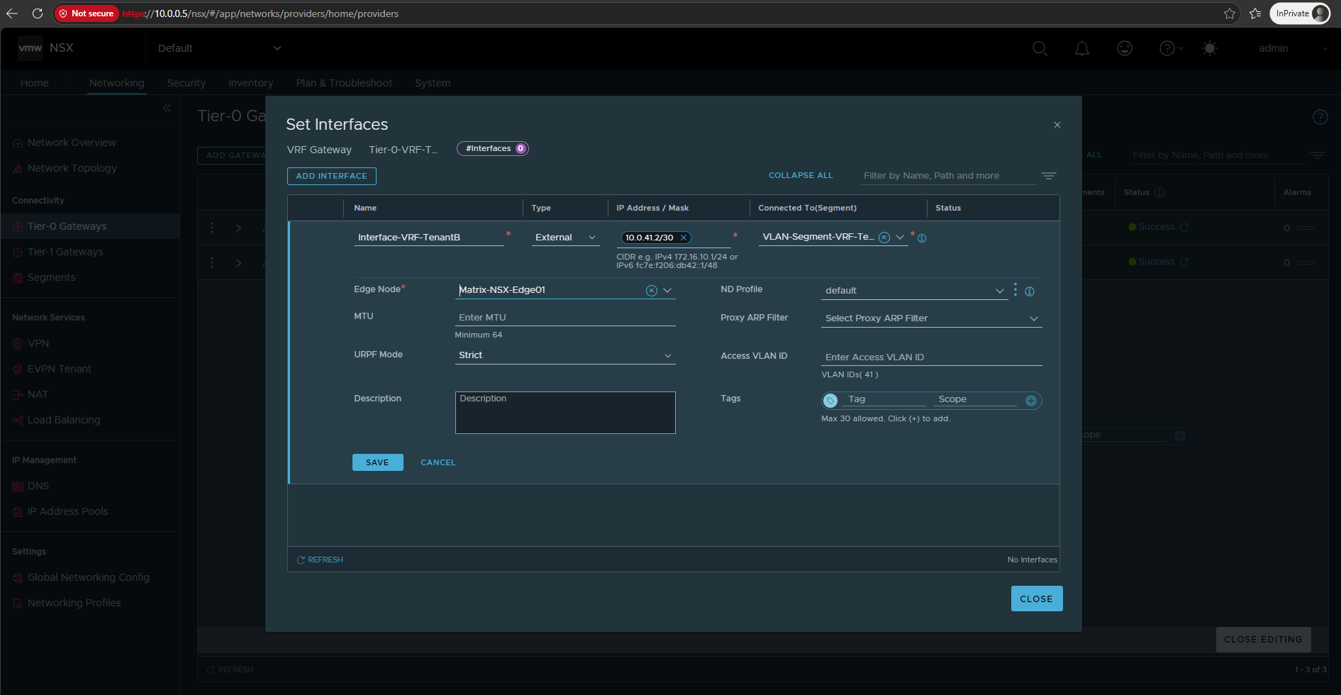
TenantB uses 10.0.41.2/30 on the NSX side, while 10.0.41.1/30 will be assigned to the corresponding Ubuntu Router Linux VRF interface.
Navigate to Networking → Tier-0 Gateways → Tier-0-VRF-TenantB → Interfaces and GRE Tunnels → Set → Add Interface.
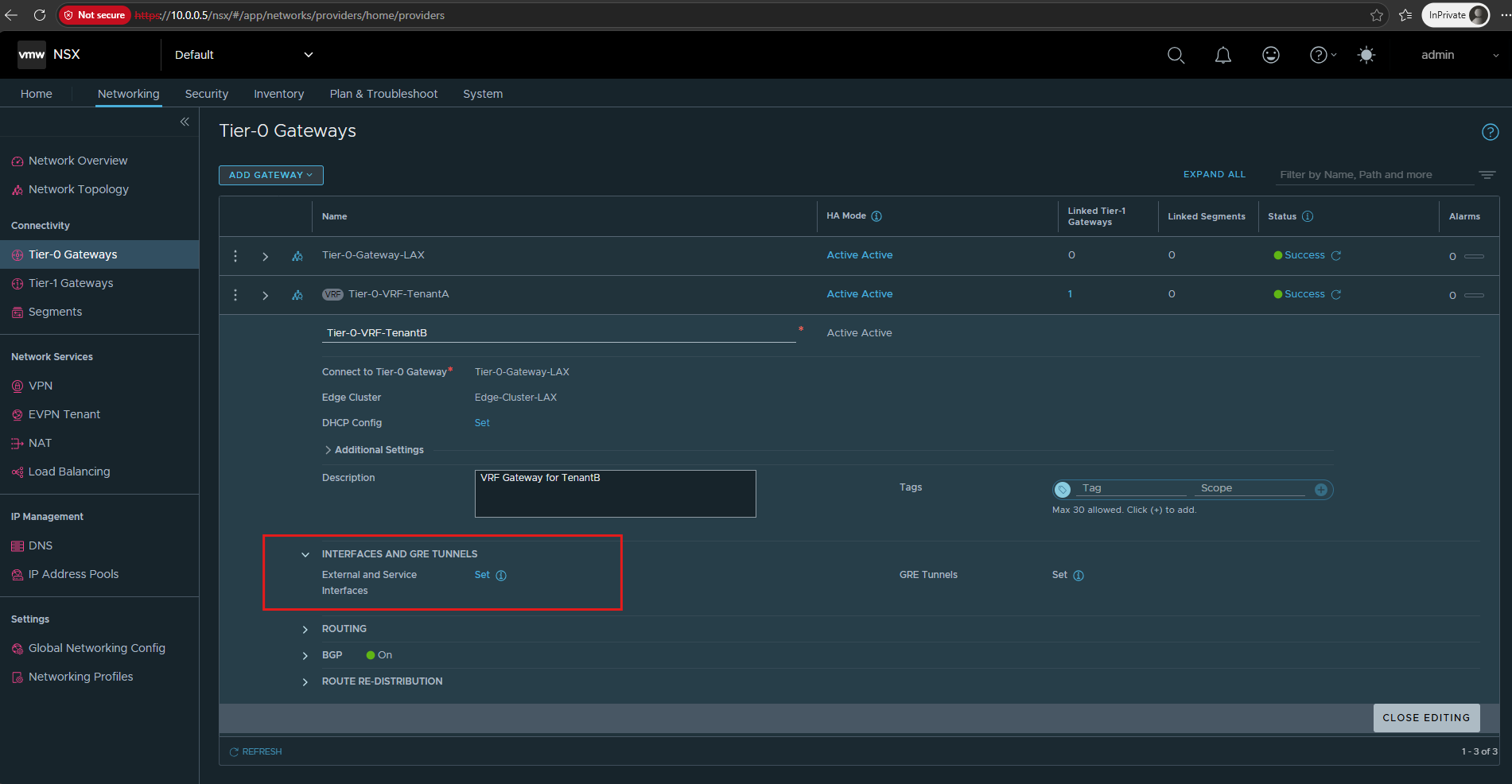
Add Interface.
We assign 10.0.41.2/30 to the external interface of Tier-0-VRF-TenantB and connect it to VLAN-Segment-VRF-TenantB on VLAN 41. The interface is hosted on our existing NSX Edge node, Matrix-NSX-Edge01, and will communicate with the Ubuntu router at 10.0.41.1/30.
Click Save and confirm the interface is successfully created
Configure the TenantB VRF and VLAN Interface on the Ubuntu Router
Next, we extend our existing Ubuntu router configuration by creating a dedicated Linux VRF for TenantB, using routing table 1002.
We also create VLAN interface ens224.41 on our existing trunk interface ens224 and assign 10.0.41.1/30. This provides the Layer-3 connection to the TenantB Tier-0 VRF at 10.0.41.2/30, while keeping both tenants in separate routing domains.
Open the file:
nano /etc/netplan/60-nsx-vrf.yaml
Under the existing vlans: section, add:
      ens224.41:
        id: 41
        link: ens224
        addresses:
          - 10.0.41.1/30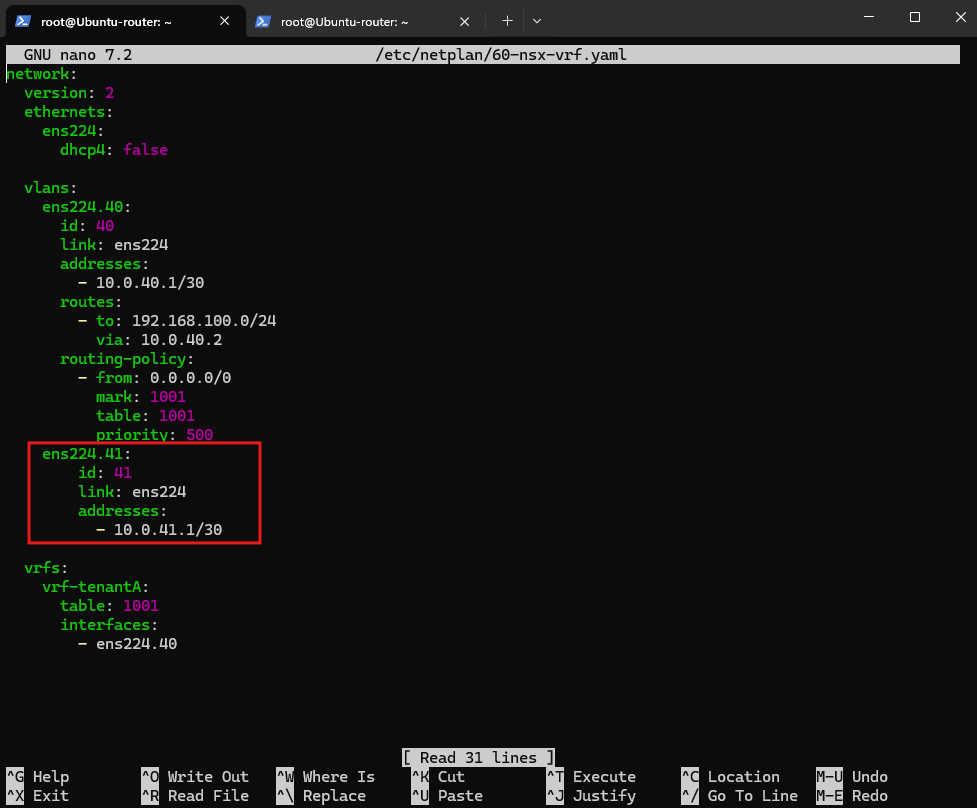
Under the existing vrfs: section, add:
      vrf-tenantB:
        table: 1002
        interfaces:
          - ens224.41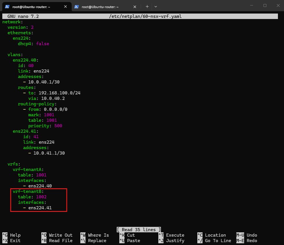
Then validate and apply:
netplan generate
netplan apply
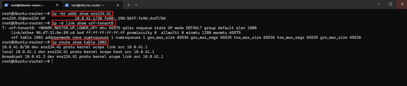
Verify the new interface and VRF:
The output confirms that VLAN interface
ens224.41and Linux VRFvrf-tenantBare operational. Routing table1002contains the directly connected10.0.41.0/30network, providing the dedicated Layer-3 handoff toward the TenantB NSX Tier-0 VRF gateway.
ip -br addr show ens224.41
ip -d link show vrf-tenantB
ip route show table 1002
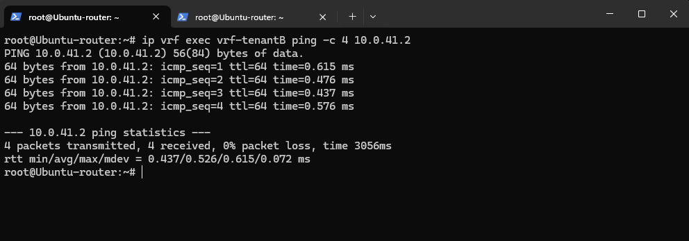
Finally, we verify connectivity from the Ubuntu router’s vrf-tenantB to the external interface of Tier-0-VRF-TenantB at 10.0.41.2.
All four ICMP requests succeed, confirming that the VLAN 41 handoff between Ubuntu and NSX is operational.
ip vrf exec vrf-tenantB ping -c 4 10.0.41.2
Configure TenantB Workload Routing
With the dedicated Tier-0 VRF gateway, VLAN 41 handoff, and Linux VRF now configured and verified, we can proceed with workload routing for TenantB.
As with TenantA in Part 2, we will connect the Tier-1 gateway to its corresponding Tier-0 VRF and configure the NSX overlay segment using the same 192.168.100.0/24 subnet, including the identical workload IP address 192.168.100.10.
The separate NSX and Linux routing domains will allow us to maintain tenant isolation while preparing both networks for simultaneous Internet access through our shared Ubuntu router.
Create the Tier-1 Gateway for TenantB
Next, we create a dedicated Tier-1 gateway for TenantB and connect it to its upstream Tier-0-VRF-TenantB.
This connects TenantB’s logical gateway to its dedicated upstream VRF without affecting the existing TenantA routing configuration.
Navigate to Networking → Tier-1 Gateways, click on Add Tier-1 Gateway, name it Tier-1-Gateway-TenantB and select for Linked Tier-0 Gateway Tier-0-VRF-TenantB.
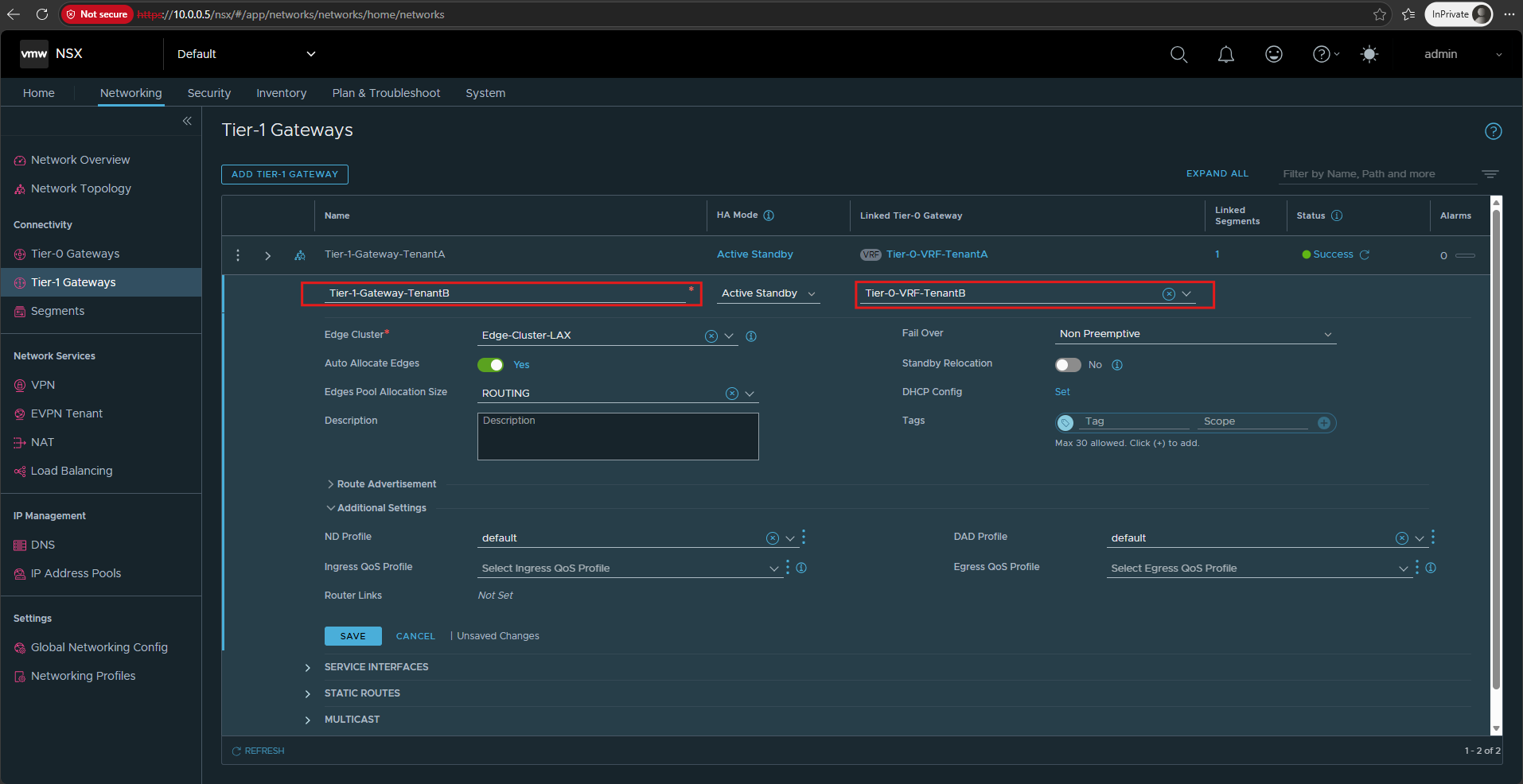
We also enable All Connected Segments & Service Ports under Route Advertisement so that TenantB’s workload subnet (192.168.100.0/24) is advertised to its Tier-0 VRF while remaining isolated from TenantA.
Click on Save.
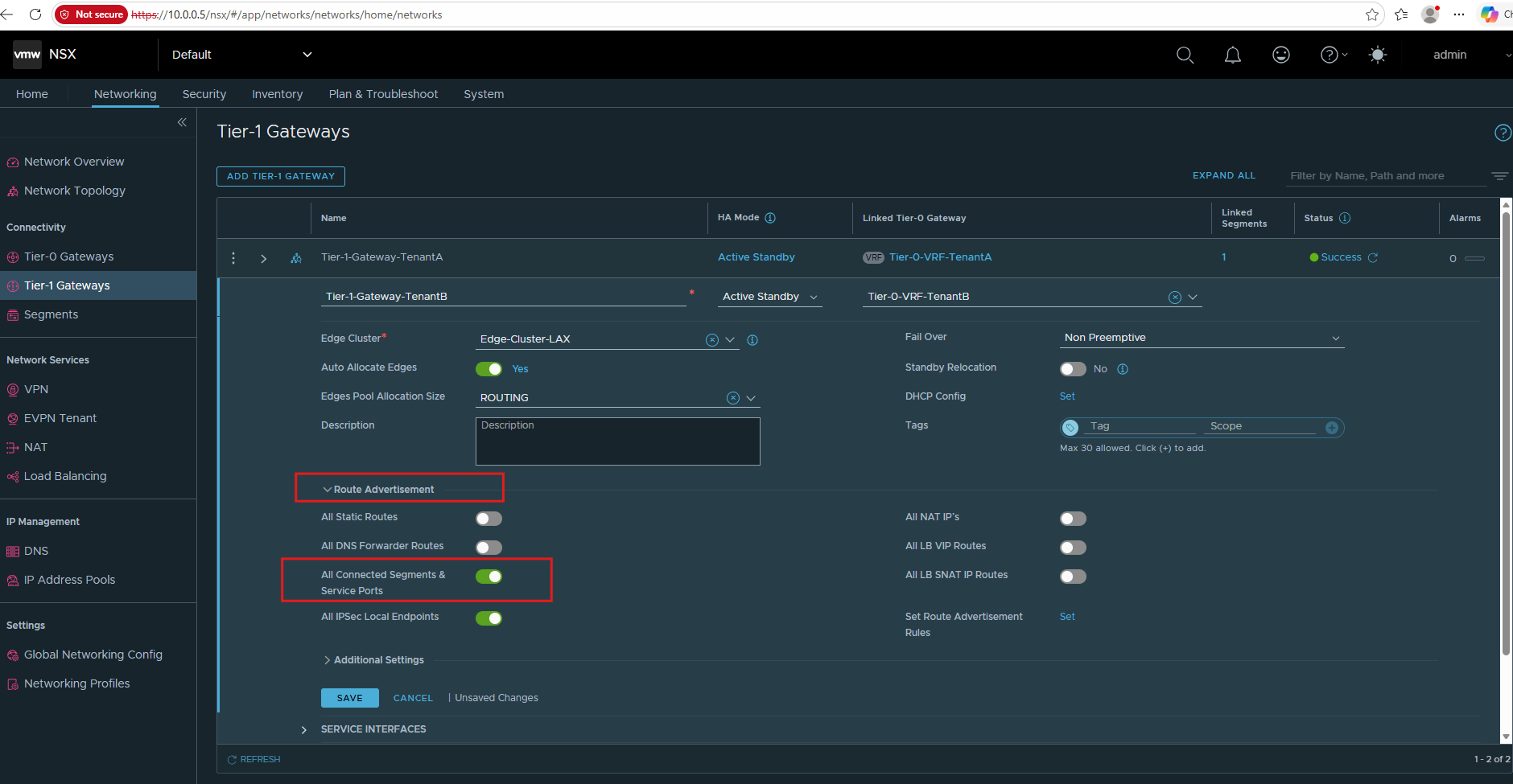
We link our existing Tier-1-Gateway-TenantB to Tier-0-VRF-TenantB, establishing the upstream routing connection for TenantB.
Both tenants now have their own Tier-1 gateways and dedicated Tier-0 VRFs, maintaining separate routing domains despite using overlapping IP address spaces.
Create and Connect the TenantB Overlay Segment
Next, we create a dedicated NSX overlay segment for TenantB and connect it to Tier-1-Gateway-TenantB.
We deliberately use the same subnet and default gateway as TenantA (192.168.100.0/24 and 192.168.100.1), demonstrating how NSX supports overlapping IP address spaces across isolated tenant networks.
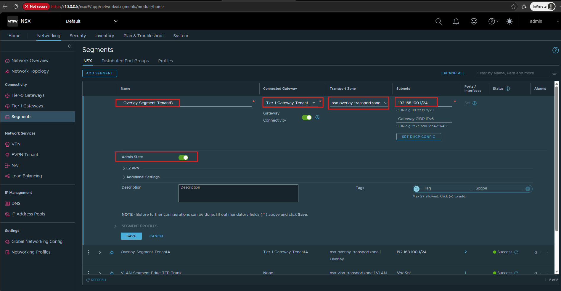
Navigate to Networking → Segments → Add Segment and configure:
Important: Use the overlay transport zone, not the VLAN transport zone. This segment is for TenantB’s workloads, whereas
VLAN-Segment-VRF-TenantBon VLAN 41 provides the external VRF handoff to the Ubuntu router.
Name: Overlay-Segment-TenantB
Connected Gateway: Tier-1-Gateway-TenantB
Transport Zone: nsx-overlay-transportzone
Subnets: 192.168.100.1/24
Admin State: Up
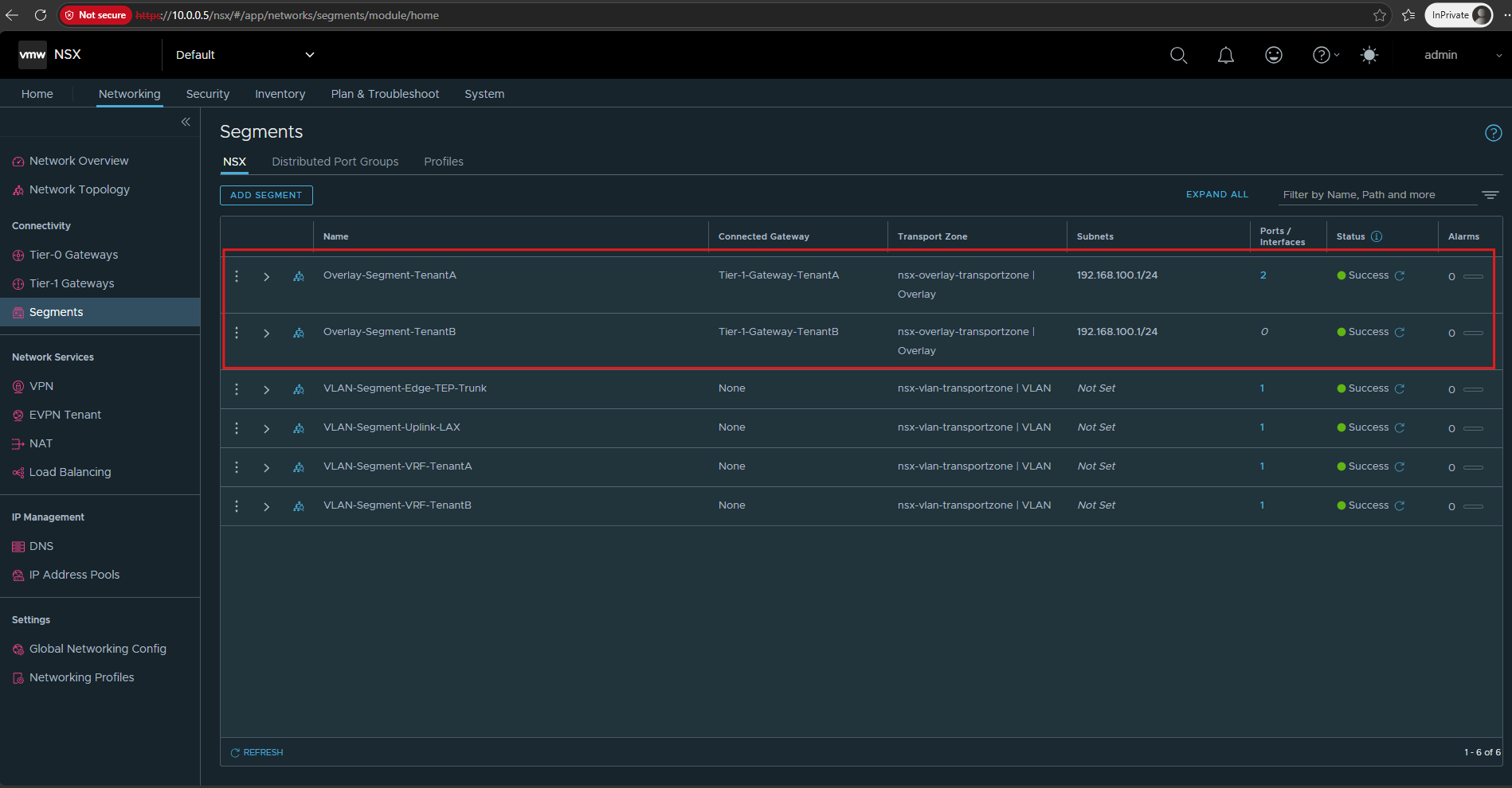
Both NSX overlay segments are now successfully configured, each connected to its own Tier-1 gateway while using the identical 192.168.100.0/24 address space.
The separate overlay networks allow both tenants to use overlapping IP addresses without sharing the same Layer-2 broadcast domain.
As shown in NSX Manager, the Overlay-Segment-TenantB currently has 0 ports/interfaces, since no virtual machine is connected to this segment yet. Once we connect our TenantB VM, the corresponding port will be created and reflected in this counter.
In Microsoft Hyper-V Network Virtualization (HNV) shown in my HNV series, the equivalent of an NSX overlay segment is a Virtual Subnet, identified by a Virtual Subnet ID (VSID) within a VM Network.
Both technologies provide logically isolated Layer-2 networks over a shared physical infrastructure, allowing different tenants to use overlapping IP address spaces.
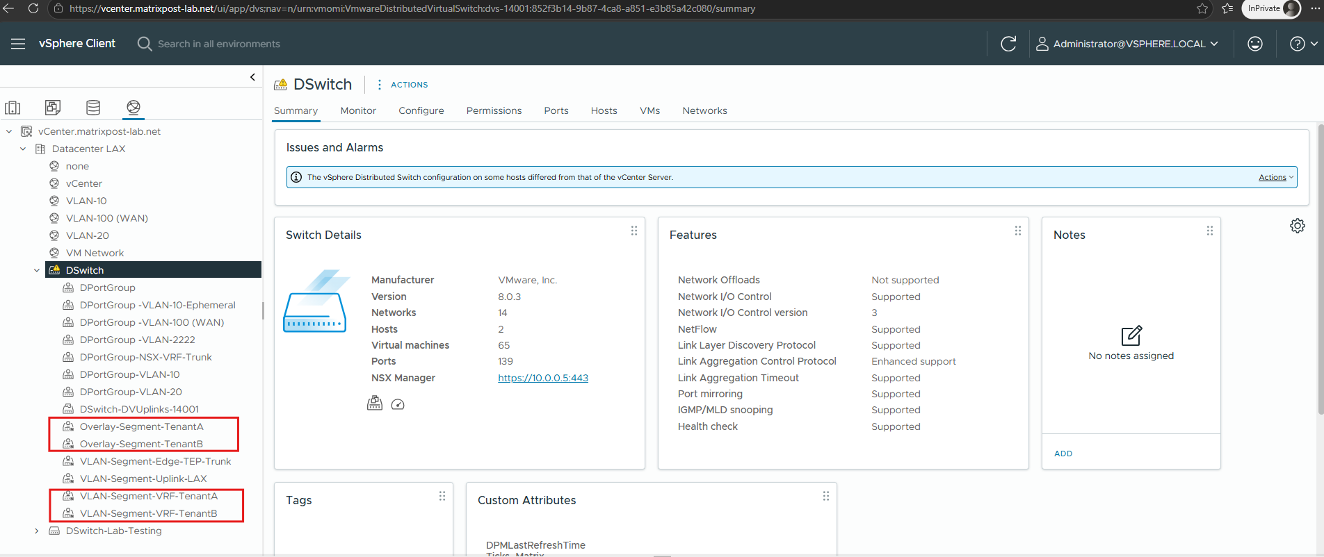
The NSX-managed overlay and VLAN segments are also visible in the vSphere Distributed Switch (DSwitch) as distributed port groups.
NSX automatically creates and manages these port groups, allowing us to connect virtual machines directly to their respective tenant overlay segments through the vSphere Client.
The small N icon next to these port groups indicates that they are managed by VMware NSX Manager, rather than being manually configured in vCenter.
Configure the TenantB VM with the Tier-1 Default Gateway
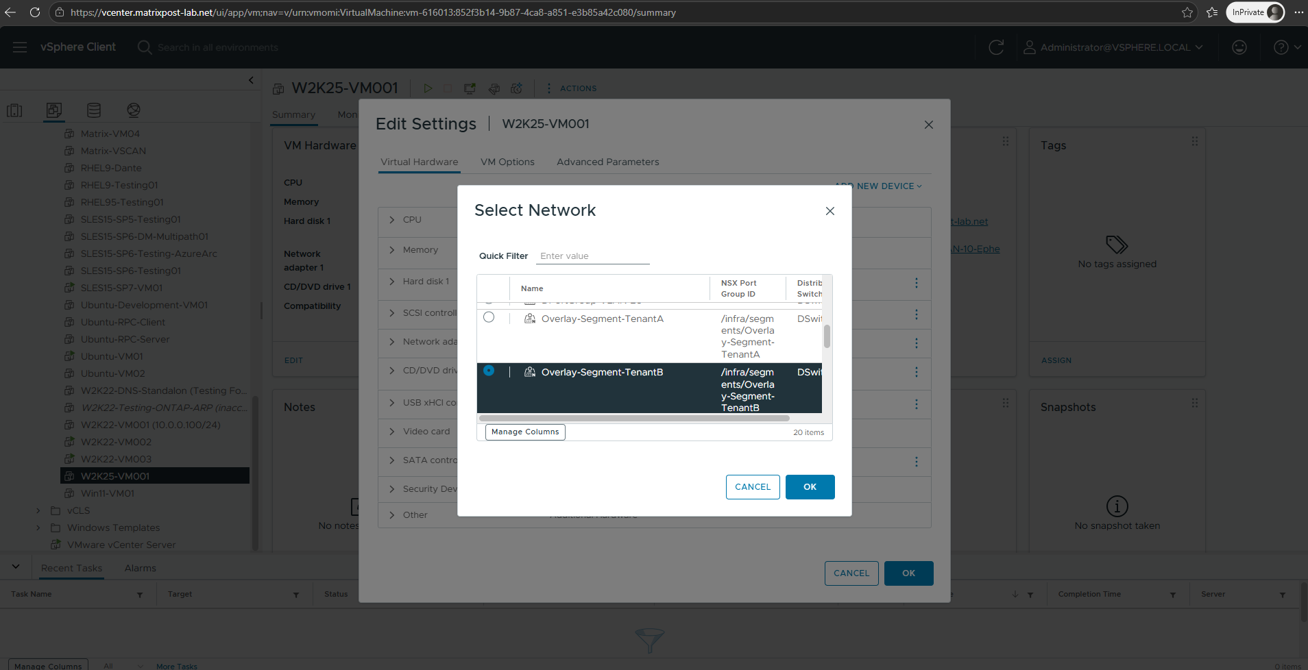
We connect our TenantB workload, W2K25-VM001, to Overlay-Segment-TenantB by selecting the corresponding NSX-managed network in the VM’s network adapter settings in vCenter.
This places the VM in TenantB’s isolated overlay network, even though TenantA uses the same 192.168.100.0/24 subnet.
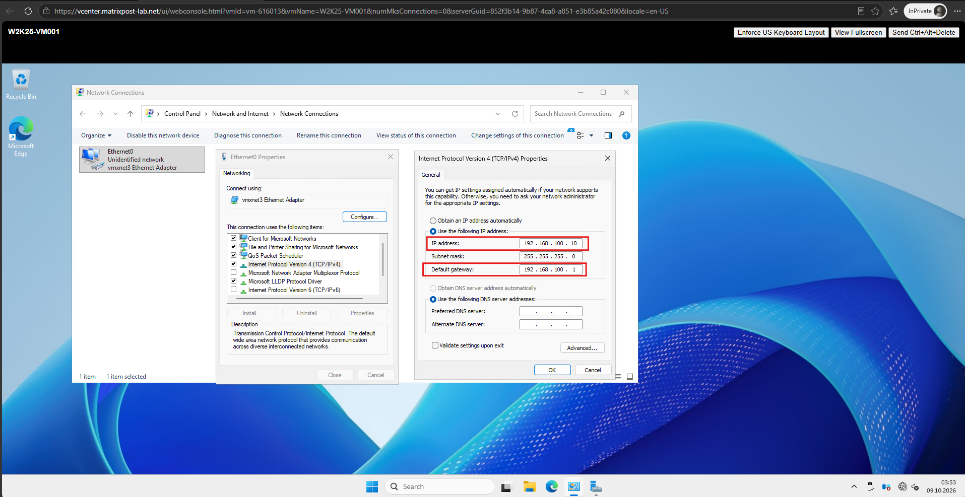
We now configure W2K25-VM001 with the IP address 192.168.100.10/24 and default gateway 192.168.100.1, identical to our TenantA workload.
Although both VMs use the same IP address and default gateway, they belong to separate NSX overlay segments and Tier-1 gateways, keeping their network traffic isolated.
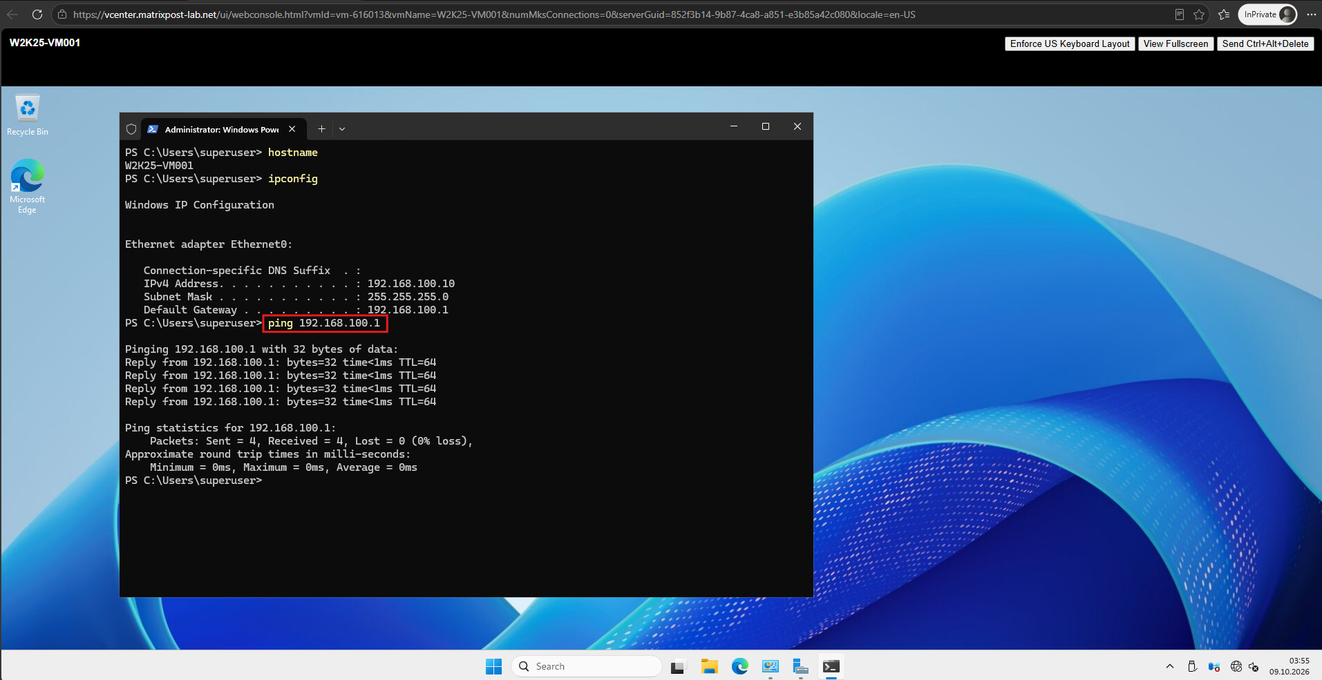
We verify the network configuration of W2K25-VM001 using ipconfig and successfully ping the TenantB Tier-1 gateway at 192.168.100.1 with 0% packet loss.
This confirms that our TenantB workload can communicate with its dedicated NSX Tier-1 gateway, even though TenantA uses the same IP subnet and gateway address in its separate overlay network.
Configure TenantB Routing Between NSX and Ubuntu
Now that our TenantB workload can successfully reach its Tier-1 gateway, we configure the routing between the NSX Tier-0 VRF and our Ubuntu router.
As with TenantA, we use a dedicated VLAN handoff (VLAN 41) and the corresponding Linux VRF (vrf-tenantB, routing table 1002) to maintain separate routing domains despite the overlapping 192.168.100.0/24 networks.
We add the persistent return route for TenantB to our existing Netplan configuration /etc/netplan/60-nsx-vrf.yaml.
Under vlans → ens224.41, add:
        routes:
          - to: 192.168.100.0/24
            via: 10.0.41.2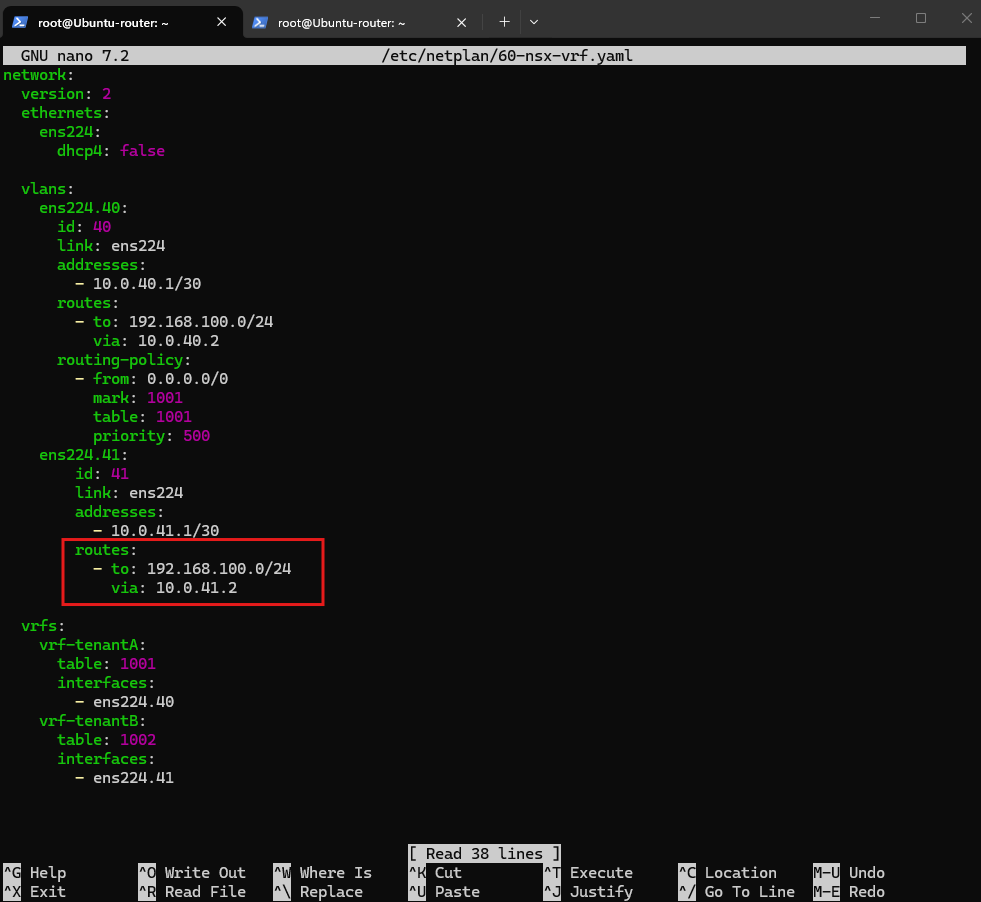
This mirrors TenantA’s configuration, but uses the TenantB VLAN interface and NSX Tier-0 VRF address.
Validate and apply:
sudo netplan generate
sudo netplan apply
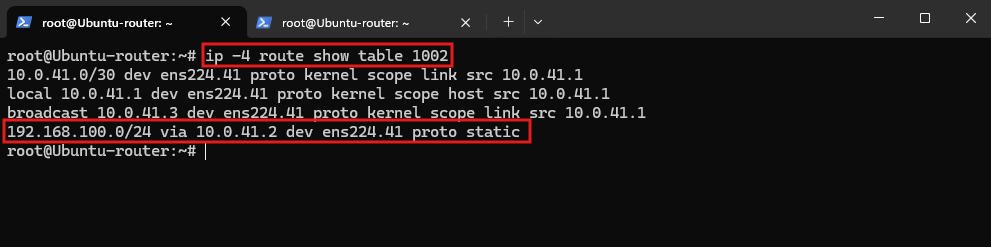
Then we verify that the route belongs to routing table 1002:
The output confirms that traffic destined for the TenantB workload subnet
192.168.100.0/24is routed throughens224.41to the NSX Tier-0 VRF gateway at10.0.41.2.Although TenantA uses the same workload subnet, both routes remain isolated in their respective Linux VRF routing tables (
1001and1002).
ip -4 route show table 1002
Configure the Default Route on the TenantB Tier-0 VRF Gateway
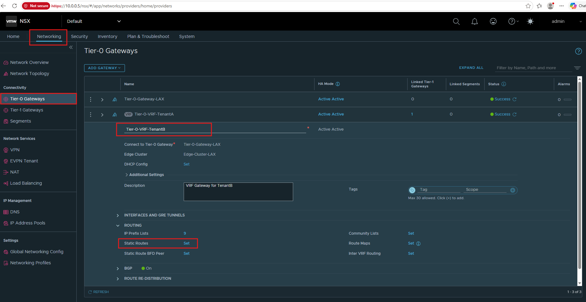
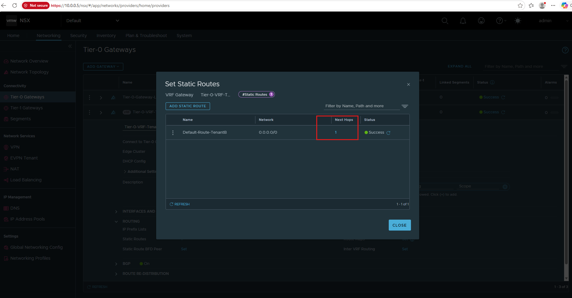
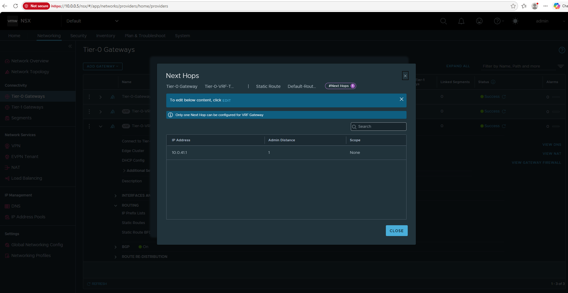
Next, we configure the default route on Tier-0-VRF-TenantB to forward traffic destined for external networks to our Ubuntu router at 10.0.41.1.
As with TenantA, this provides the upstream routing path through the dedicated VLAN 41 connection while keeping both tenants in separate VRF routing domains.
In NSX Manager, navigate to Networking → Tier-0 Gateways and expand Tier-0-VRF-TenantB.
Under Routing → Static Routes, add the following:
Name:	     Default-Route-TenantB
Network:	  0.0.0.0/0
Next Hop IP:  10.0.41.1
Scope: 	      Leave unset
Verify End-to-End TenantB Routing
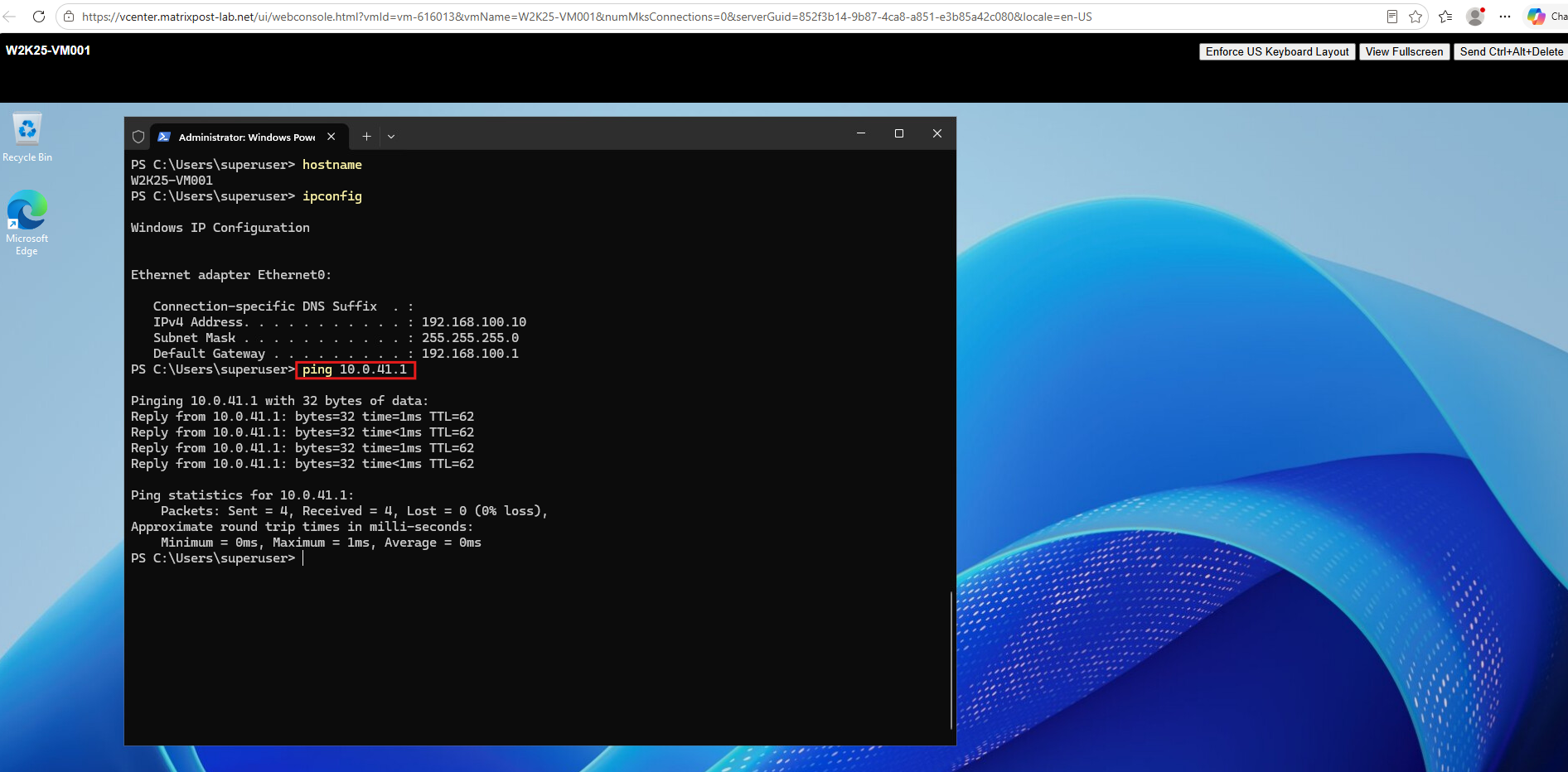
With the default route configured on Tier-0-VRF-TenantB and the corresponding return route installed in Linux routing table 1002, we can now verify connectivity between our TenantB workload and the Ubuntu router.
This test confirms that traffic can traverse the TenantB Tier-1 gateway, Tier-0 VRF, and dedicated VLAN 41 handoff.
On W2K25-VM001 (192.168.100.10), we run:
The ping to our Ubuntu router (
10.0.41.1) succeeds with 0% packet loss.This confirms end-to-end connectivity through the TenantB overlay network, Tier-1 gateway, Tier-0 VRF, and VLAN 41 handoff to the dedicated Linux VRF.
ping 10.0.41.1
Configure the Default Route for the TenantB Linux VRF
Now that we have verified end-to-end connectivity between the TenantB workload and our Ubuntu router, we configure the default route for the TenantB Linux VRF.
This route forwards traffic destined for external networks through the Ubuntu router’s existing WAN interface (ens256), while the dedicated VRF routing table (1002) maintains TenantB’s separate routing domain.
Configure Tenant-Specific Connection Tracking for TenantB
As described in Part 2, we use Netfilter connection marks (ct mark) together with policy routing (fwmark) to direct returning traffic through the appropriate tenant routing table.
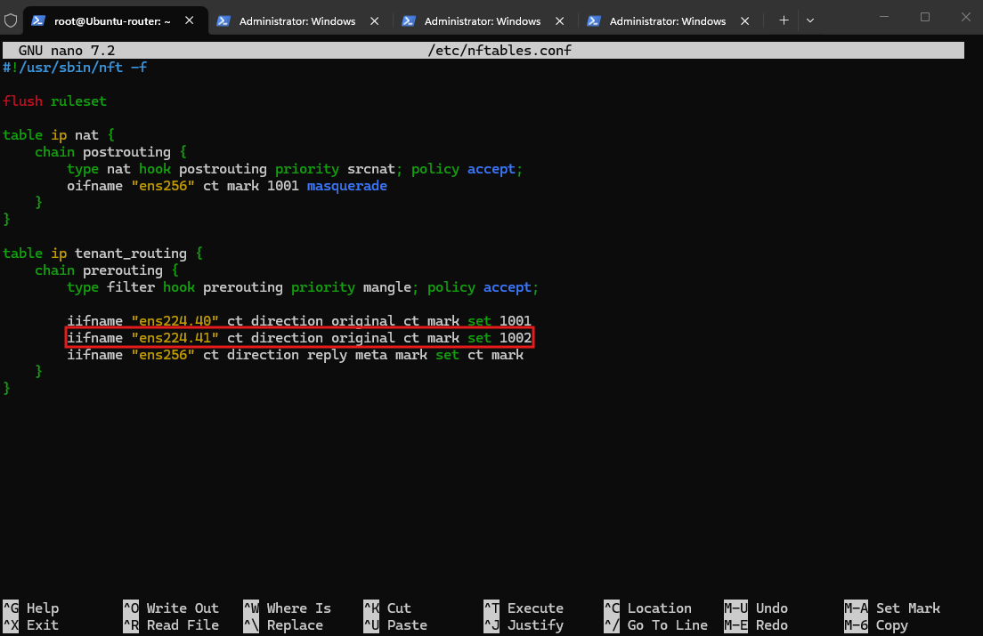
We now extend our existing /etc/nftables.conf configuration to include TenantB, using connection mark 1002 and its dedicated VLAN interface ens224.41. TenantA continues to use connection mark 1001.
In the existing table ip tenant_routing, extend the prerouting chain:
The existing TenantA rules remain unchanged; we’re adding only the TenantB rule.
iifname "ens224.41" ct direction original ct mark set 1002
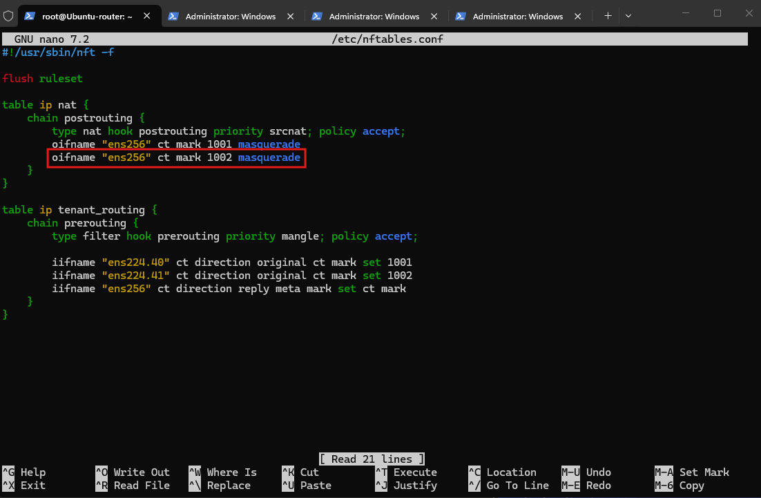
We also add a second masquerade rule to the existing postrouting chain for TenantB, using connection mark 1002. The existing TenantA rule with connection mark 1001 remains unchanged, allowing both tenants to use the shared WAN interface ens256 for outbound traffic.
oifname "ens256" ct mark 1002 masquerade
Validate and load the configuration:
# verify:
nft -c -f /etc/nftables.conf

# load and activate the rules
nft -f /etc/nftables.conf
Configure Persistent Policy Routing for TenantB
Next, we extend the existing Netplan configuration in /etc/netplan/60-nsx-vrf.yaml to add persistent policy-based routing for TenantB.
As with TenantA, we use a firewall mark to select the corresponding VRF routing table, assigning mark 1002 to table 1002 while leaving TenantA’s existing policy unchanged.
Add the following under ens224.41, alongside its existing configuration:
routing-policy:
  - from: 0.0.0.0/0
    mark: 1002
    table: 1002
    priority: 500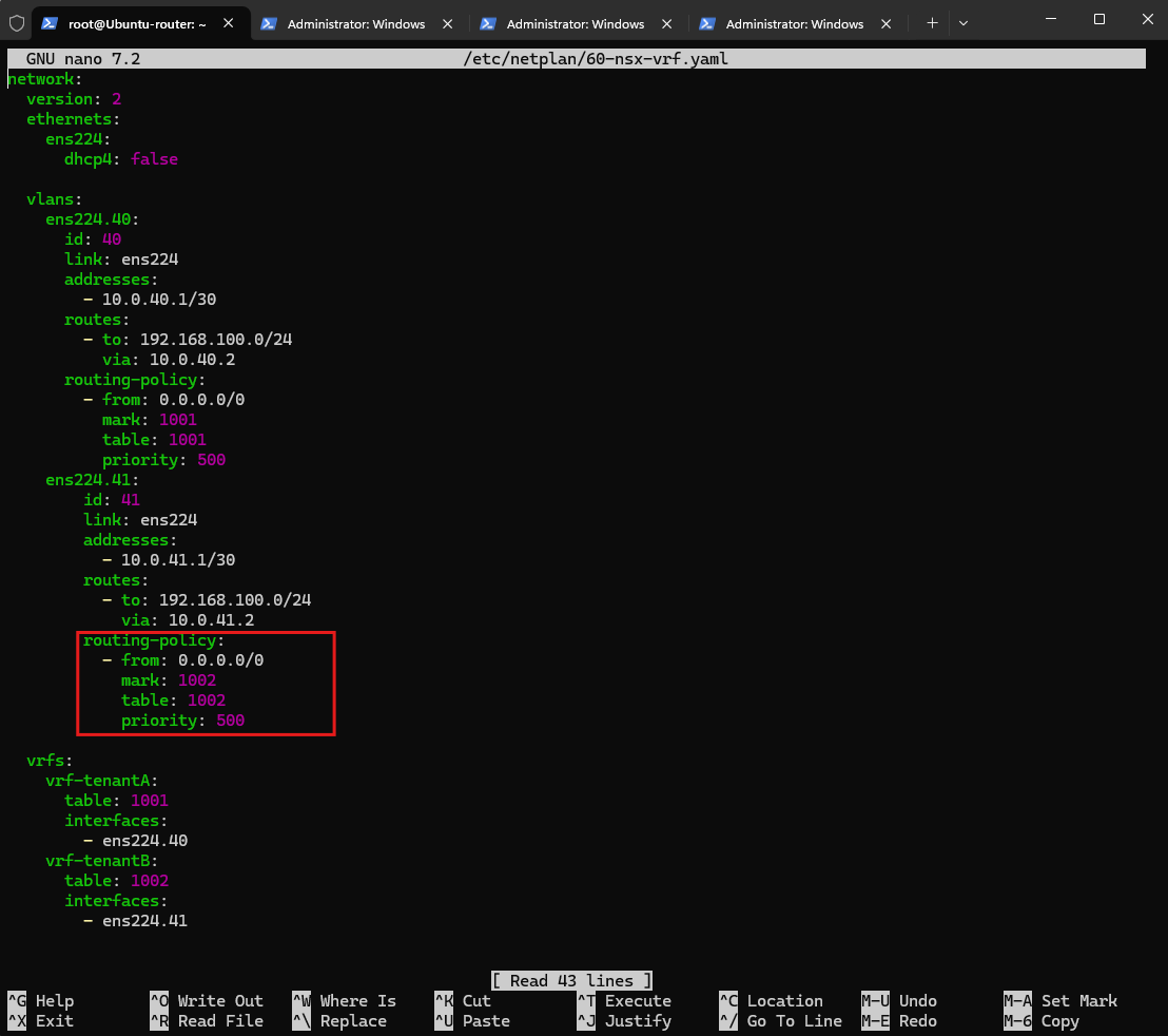
Validate and apply:
netplan generate
netplan apply
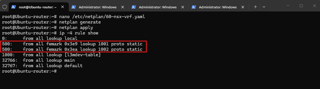
Verify:
The output confirms that both tenant-specific policy-routing rules are active. Firewall mark
1001selects TenantA’s routing table1001, while mark1002selects TenantB’s routing table1002, keeping their routing decisions separate even though both tenants use the same192.168.100.0/24subnet.
ip -4 rule show
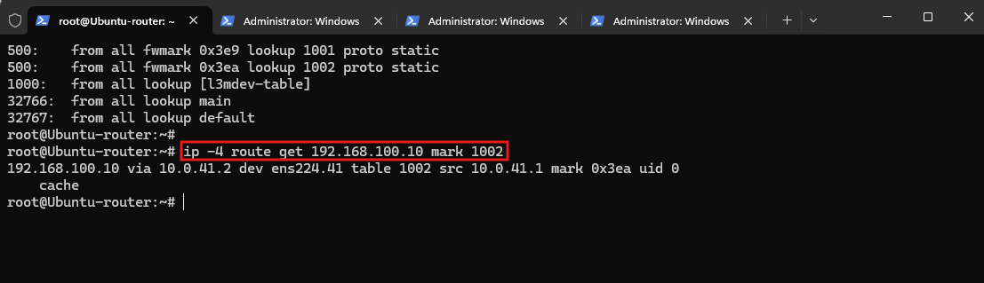
Next, let’s verify TenantB’s route selection:
The routing lookup confirms that traffic marked with
1002uses TenantB’s dedicated routing table1002and is forwarded throughens224.41to the NSX Tier-0 VRF gateway at10.0.41.2.This verifies that the correct tenant-specific route is selected despite both tenants using the overlapping
192.168.100.0/24subnet.
ip -4 route get 192.168.100.10 mark 1002
Verify TenantB Internet Connectivity
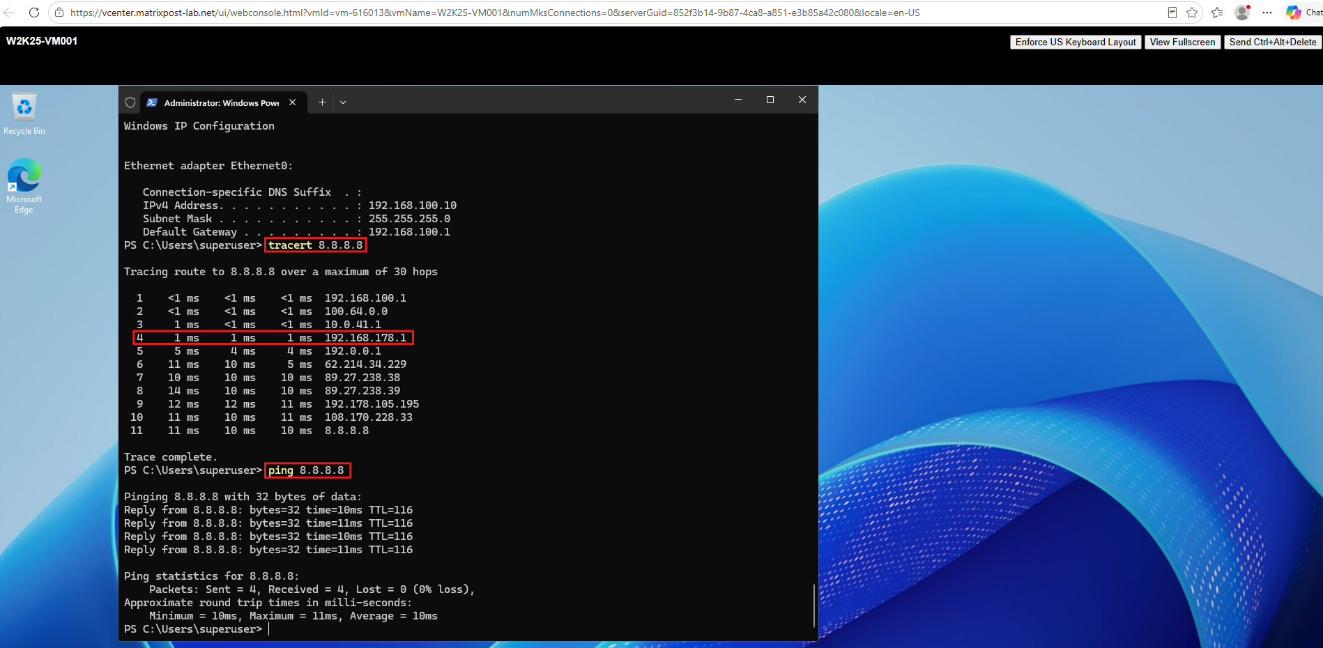
Finally, we verify Internet connectivity from the TenantB Windows VM by pinging 8.8.8.8. Both TenantA and TenantB can now reach the Internet through the shared Ubuntu router and WAN interface, even though their VMs use the identical IP address 192.168.100.10.
The traceroute confirms that TenantB traffic is forwarded through its dedicated NSX Tier-1 and Tier-0 VRF gateways, the Ubuntu router at
10.0.41.1, and finally the shared WAN gateway at192.168.178.1.The successful ping to
8.8.8.8confirms end-to-end Internet connectivity, even though TenantA uses the identical workload IP address192.168.100.10.
Verify Simultaneous TCP Connections from Overlapping Tenants
To further verify our configuration, we establish simultaneous RDP connections from both TenantA and TenantB to the same Azure Windows Server VM (20.71.240.206) and inspect the connection-tracking table on our Ubuntu router.
Both Windows VMs use the identical IP address 192.168.100.10. Nevertheless, the output below shows two separate TCP connections in the ESTABLISHED state, each associated with its corresponding tenant-specific connection mark (1001 and 1002).
conntrack -L -p tcp --dport 3389

Our existing configuration combines NSX Tier-0 VRFs, Linux VRFs, nftables connection marks, policy routing, and Source NAT.
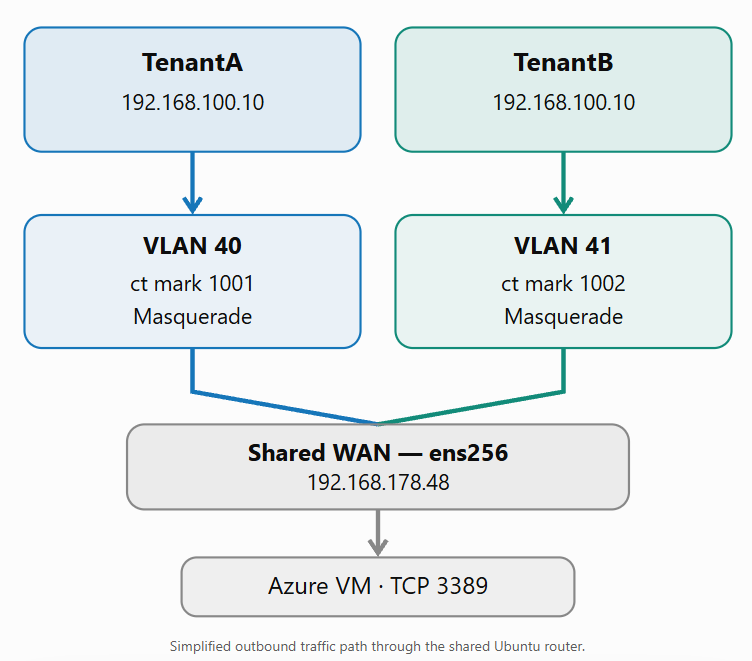
1. Tenant-specific forwarding through NSX
Traffic from TenantA and TenantB passes through their respective NSX Tier-1 and Tier-0 VRF gateways before reaching the Ubuntu router over VLAN 40 or VLAN 41. Although both tenants use 192.168.100.0/24, their traffic arrives on different VLAN interfaces.
2. Connection marking with nftables
The Ubuntu router identifies the incoming tenant interface and assigns connection mark 1001 to TenantA or 1002 to TenantB. These marks are stored in the Linux connection-tracking entries and remain associated with the respective connections.
3. Outbound Source NAT
Both tenants use the same WAN interface, ens256. The corresponding nftables masquerade rules translate their private source addresses to the WAN address 192.168.178.48, allowing outbound traffic to reach external networks through the existing default route.
4. Return traffic and policy routing
When response packets arrive on ens256, Linux conntrack identifies the existing connection and reverses the Source NAT translation. Our nftables rule restores the connection mark as a packet mark (fwmark), which the Linux policy-routing rules use to select routing table 1001 or 1002. The response is then forwarded through the appropriate tenant VLAN and NSX Tier-0 VRF gateway.
5. How the two RDP connections are distinguished
Although both RDP connections originate from the identical IP address 192.168.100.10 and connect to the same Azure VM (20.71.240.206:3389), Windows assigns different ephemeral source ports (49680 and 51188).
Linux conntrack identifies TCP connections using their 5-tuple, consisting of the source IP address, source port, destination IP address, destination port, and protocol. Because the source ports differ, conntrack recognizes our two RDP sessions as separate connections.
Importantly, this connection identification is independent of the connection marks (ct mark) we configured with nftables. These marks are additional metadata associated with already identified connections and are used for tenant-specific NAT and policy routing, not for distinguishing connections.
Consequently, our current configuration works because the two connections have different source ports. If both tenants establish connections with identical 5-tuples, their entries can collide in the default conntrack zone, regardless of whether we assign connection marks 1001 and 1002.
To reliably isolate overlapping tenant connections, including identical 5-tuples, we therefore need to configure dedicated conntrack zones for each tenant.
Note: In our setup, the connection marks ensure that returning traffic is forwarded from the Ubuntu router through the correct VLAN interface toward the respective VMware NSX tenant, even though both tenants use the identical
192.168.100.0/24subnet.However, on the external side of our Ubuntu router, where both tenants share the WAN interface
ens256and communicate through the FritzBox with the Internet, Linux conntrack currently uses the default connection-tracking zone. Within this zone, connections are identified by their 5-tuples (source and destination IP addresses, source and destination ports, and protocol), independently of the connection marks.Consequently, connections with identical 5-tuples can collide, even when their connection marks differ.
This is because returning packets arriving on the shared WAN interface
ens256must first be associated with an existing connection by Linux conntrack, before nftables can retrieve the stored connection mark and apply it as a firewall mark (fwmark) for tenant-specific policy routing.To reliably separate such connections, we need to extend our configuration with dedicated conntrack zones for each tenant, including correct handling of return traffic through the shared WAN interface.
Configure Tenant-Specific Linux Conntrack Zones
So far, we have successfully configured two VMware NSX tenants with overlapping IP subnets, using Linux VRFs, connection marks, policy routing, and Source NAT to provide Internet connectivity through our shared Ubuntu router.
However, as demonstrated in the previous section, Linux conntrack currently identifies connections within the default connection-tracking zone using their 5-tuples. To prevent collisions when both tenants establish connections with identical 5-tuples, we will configure dedicated conntrack zones for TenantA and TenantB.
We will use zone 1001 for TenantA and zone 1002 for TenantB, matching our existing connection marks and VRF routing tables. Unlike connection marks, conntrack zones provide separate namespaces for tracking connections, allowing otherwise identical connection tuples to coexist.
Because both tenants share the WAN interface ens256 and its external IP address 192.168.178.48, we must also ensure that returning packets are assigned to the correct zone before connection tracking and reverse NAT take place.
Inspect the Existing NAT and Connection-Tracking Entries
Before configuring dedicated conntrack zones, we first inspect the existing connection-tracking entries and NAT mappings on our Ubuntu router. This allows us to verify how connections from both tenants are currently tracked through the shared WAN interface ens256 and provides a baseline for the upcoming configuration changes.
First, we need to distinguish two things:
- Tenant-side tracking: Assign zone
1001to traffic enteringens224.40and zone1002to traffic enteringens224.41. - WAN-side tracking: Ensure return traffic arriving on
ens256is assigned to the correct zone before conntrack performs its lookup.
Because both tenants share the WAN address 192.168.178.48, we’ll need distinct translated TCP/UDP source-port ranges or another unambiguous mapping. Conntrack zones alone won’t resolve that shared-WAN ambiguity.
We run the following command while the RDP connections from both tenants are established:
conntrack -L -p tcp --dport 3389 -o extended

The output above confirms two established RDP connections originating from the identical tenant IP address 192.168.100.10. Both connections are masqueraded through the shared WAN address 192.168.178.48 and carry their respective connection marks (1001 and 1002).
However, the connections currently use different TCP source ports (49773 and 49675), which allows Linux conntrack to distinguish them within the default connection-tracking zone. This demonstrates why dedicated conntrack zones are necessary to reliably support connections with otherwise identical 5-tuples.
Configure Dedicated Conntrack Zones for TenantA and TenantB
Next, we configure dedicated Linux conntrack zones for both tenants. TenantA will use zone 1001, while TenantB will use zone 1002, matching our existing connection marks and VRF routing tables.
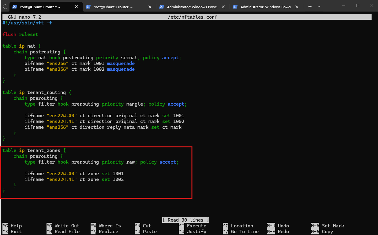
Conntrack zones must be assigned before Linux performs connection tracking. Therefore, we introduce a new nftables prerouting chain with priority raw (-300), which executes before the conntrack lookup at priority -200.
We add a new tenant_zones table to /etc/nftables.conf, assigning conntrack zones 1001 and 1002 to the corresponding tenant VLAN interfaces. By using the raw priority, these rules execute before Linux performs connection tracking, allowing each tenant to use a separate connection-tracking namespace.
Note: We do not activate these rules yet. Return traffic arriving through the shared WAN interface
ens256must also be assigned to the correct zone before conntrack runs. Otherwise, the existing connections may no longer be matched correctly.
table ip tenant_zones {
    chain prerouting {
        type filter hook prerouting priority raw; policy accept;

        iifname "ens224.40" ct zone set 1001
        iifname "ens224.41" ct zone set 1002
    }
}
For now, we just validate the updated file:
nft -c -f /etc/nftables.conf

Configure WAN-Side Conntrack Zone Selection and NAT Port Mapping
Now comes the critical part: return traffic through our shared WAN interface ens256.
We already assigned conntrack zones 1001 and 1002 to the tenant VLAN interfaces. However, returning packets arrive on the same WAN interface and destination IP address (192.168.178.48).
To distinguish them before conntrack performs its lookup, we can reserve separate translated TCP/UDP source-port ranges:
| Tenant | Conntrack zone | Proposed NAT source-port range |
|---|---|---|
| TenantA | 1001 | 40000–49999 |
| TenantB | 1002 | 50000–59999 |
For example, a returning TCP packet addressed to 192.168.178.48:45000 would be assigned to zone 1001, while one addressed to port 55000 would be assigned to zone 1002.
One important detail: We must also handle ICMP separately because it has no TCP/UDP ports.
Before extending our nftables configuration, we verify the installed nftables version and Linux kernel using nft --version and uname -r.
Our Ubuntu router runs nftables
1.0.9and kernel6.8.0-146-generic, both supporting the required conntrack zones, NAT port ranges, and early packet classification atrawpriority.
nft --version
uname -r

First, we reserve separate NAT source-port ranges for both tenants. This allows returning TCP and UDP packets on the shared WAN interface ens256 to be associated with the correct conntrack zone before connection tracking takes place.
In /etc/nftables.conf, we replace the two existing masquerade rules in table ip nat with:
oifname "ens256" meta l4proto tcp ct mark 1001 masquerade to :40000-49999
oifname "ens256" meta l4proto udp ct mark 1001 masquerade to :40000-49999
oifname "ens256" meta l4proto tcp ct mark 1002 masquerade to :50000-59999
oifname "ens256" meta l4proto udp ct mark 1002 masquerade to :50000-59999
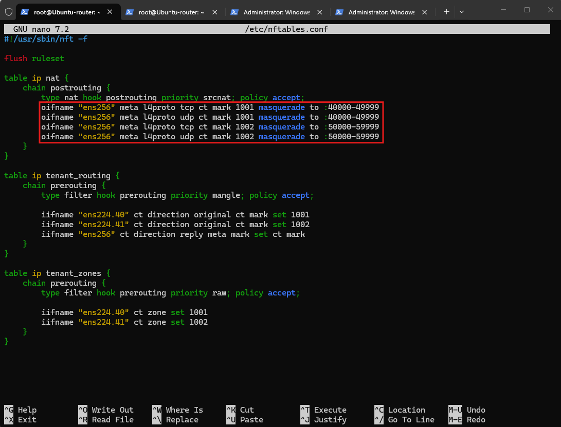
Then validate:
nft -c -f /etc/nftables.conf

Next, we add the WAN-side conntrack zone assignments to the existing table ip tenant_zones, inside its prerouting chain, immediately after the two tenant-interface rules:
These rules assign returning packets to their tenant’s conntrack zone before the conntrack lookup, using the destination port on the shared WAN interface.
iifname "ens256" meta l4proto tcp tcp dport 40000-49999 ct zone set 1001
iifname "ens256" meta l4proto udp udp dport 40000-49999 ct zone set 1001
iifname "ens256" meta l4proto tcp tcp dport 50000-59999 ct zone set 1002
iifname "ens256" meta l4proto udp udp dport 50000-59999 ct zone set 1002
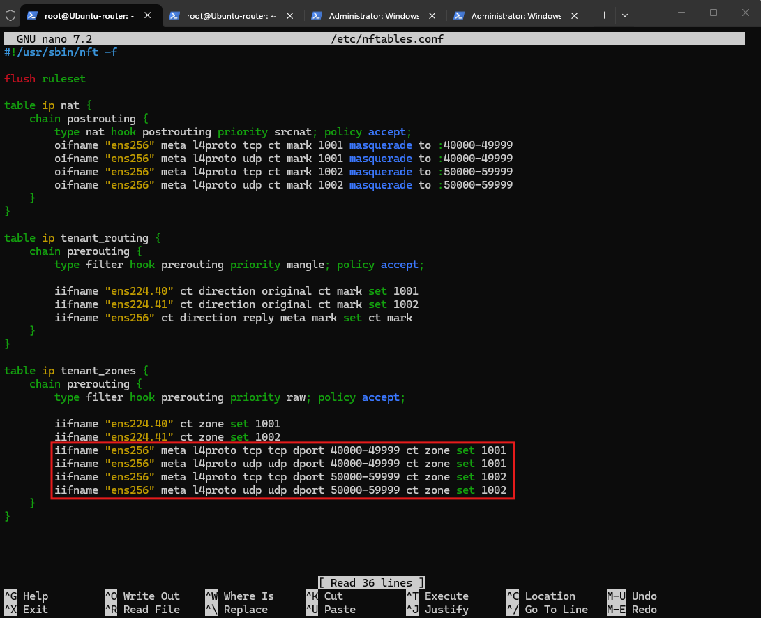
Validate again:
nft -c -f /etc/nftables.conf

Since ICMP does not use TCP or UDP ports, our port-based WAN-side conntrack zone selection cannot distinguish ICMP replies between the two tenants. We therefore keep ICMP traffic in the default conntrack zone (0) and retain the existing masquerading behavior for ping traffic.
To achieve this, we add dedicated ICMP masquerade rules and restrict the tenant-side conntrack zone assignments to TCP and UDP. This preserves ICMP connectivity while providing separate conntrack namespaces for TCP and UDP connections.
Note: Our configuration provides separate conntrack zones for TCP and UDP traffic. ICMP remains in the default conntrack zone (
0). Unlike TCP and UDP, ICMP Echo Requests do not use source and destination ports. Instead, Linux conntrack uses the ICMP identifier, together with the source and destination IP addresses and ICMP type/code, to distinguish individual ping sessions.This explains why simultaneous ping requests from both tenants currently work despite their overlapping IP addresses: their ICMP identifiers differ. However, if both tenants happen to use identical identifiers for otherwise identical connection tuples, a conntrack collision may occur, potentially causing incorrect return routing or packet loss.
Commercial firewall platforms address overlapping networks through tenant-specific connection tracking, virtual routing and firewall contexts, and appropriate NAT or traffic-classification mechanisms.
We will examine these approaches in more detail in Part 4 of this series.
To keep ICMP traffic in the default conntrack zone (0), we restrict our tenant-side zone assignments to TCP and UDP. Since our new NAT rules also apply exclusively to these protocols, we add separate ICMP masquerade rules to preserve the existing NAT functionality for ping traffic.
No explicit conntrack zone assignment is required for ICMP, as Linux automatically uses zone 0 when no other zone is specified.
In /etc/nftables.conf and table ip tenant_zones, we need to replace:
iifname "ens224.40" ct zone set 1001
iifname "ens224.41" ct zone set 1002
With:
We keep the four WAN-side TCP/UDP zone rules unchanged.
iifname "ens224.40" meta l4proto { tcp, udp } ct zone set 1001
iifname "ens224.41" meta l4proto { tcp, udp } ct zone set 1002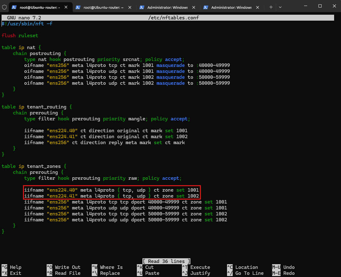
In table ip nat, we append these two rules inside the existing postrouting chain, after the four TCP/UDP masquerade rules:
oifname "ens256" meta l4proto icmp ct mark 1001 masquerade
oifname "ens256" meta l4proto icmp ct mark 1002 masquerade
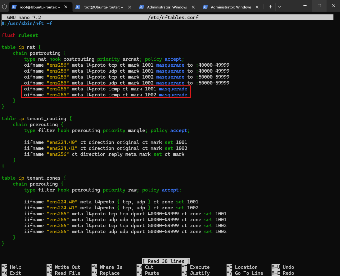
Next we just validate the new configuration:
nft -c -f /etc/nftables.conf

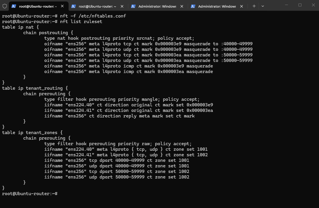
With the configuration complete and syntax validation successful, we load the updated nftables ruleset into the Linux kernel.
We then use
nft list rulesetto verify that the tenant-specific conntrack zones, NAT port ranges, and ICMP masquerade rules are active.
nft -f /etc/nftables.conf
nft list ruleset
Verify Connectivity and Conntrack Zones
After loading the updated nftables configuration, simultaneous ICMP connectivity and RDP sessions from both tenants continue to work. Inspecting the connection-tracking table confirms that TenantA and TenantB now use separate conntrack zones (1001 and 1002), despite sharing the same internal IP address and external RDP destination.
The output also confirms our NAT port mapping: TenantA retains source port 49782, while TenantB’s source port is translated from 49676 to 59953, within its dedicated NAT range. Both connections remain established, demonstrating successful tenant-specific connection tracking, NAT, and return routing through the shared WAN interface.
conntrack -L -p tcp --dport 3389 -o extended

One final distinction: This verifies isolation for the two observed TCP connections, but not yet the more demanding case where both tenants use an identical original five-tuple. That’s the ultimate test of our conntrack zones.
To verify that our configuration truly isolates overlapping tenant networks, we establish simultaneous TCP connections from both tenant VMs using exactly the same source IP address (192.168.100.10), source port (45000), destination IP address (20.71.240.206), destination port (3389), and protocol (TCP).
Since the RDP client does not allow us to specify a local TCP source port, we use PowerShell’s .NET TcpClient class to explicitly bind both connections to port 45000.
$tcp = [System.Net.Sockets.TcpClient]::new([System.Net.IPEndPoint]::new([System.Net.IPAddress]::Parse("192.168.100.10"),45000)); $tcp.Connect("20.71.240.206",3389)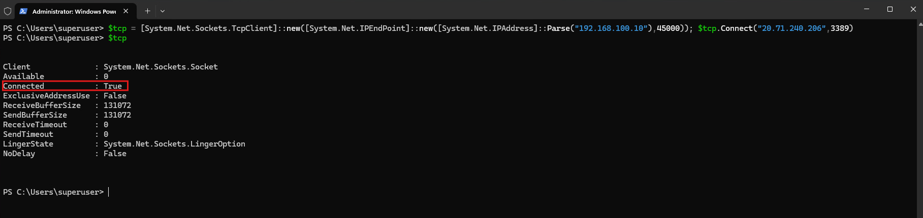
On the Ubuntu router, we monitor the connection-tracking events:
conntrack -E -p tcp --dport 3389 -o extended

The output above confirms that both connections successfully reach the ESTABLISHED state despite having identical original TCP five-tuples.
TenantA is tracked in conntrack zone 1001 and retains its original source port 45000, while TenantB is tracked in zone 1002 and receives the translated WAN source port 52552.
This demonstrates that our Linux router can reliably distinguish overlapping TCP connections using separate conntrack zones and tenant-specific NAT mappings, even when both tenants share the same external WAN interface and destination.
Final Note – WAN Routers and Firewalls in Production Environments
The Ubuntu router used in this series demonstrates how overlapping tenant networks can be isolated using Linux VRFs, connection tracking, NAT, and policy-based routing. While our configuration successfully handles identical TCP five-tuples, it is primarily intended for lab and testing purposes.
In production environments, dedicated WAN routers and firewall appliances from vendors such as Juniper, Cisco, Fortinet and Check Point are commonly used. Depending on the platform, these provide advanced features for isolating overlapping tenant networks, including VRFs, virtual routing and firewall instances, separate session tables, stateful inspection, and tenant-aware NAT.
In Part 4, we will also introduce the vendor-specific features and technologies offered by Juniper, Cisco, Fortinet, Check Point, and other WAN router and firewall platforms for isolating overlapping tenant networks, including their approaches to VRFs, connection tracking, NAT, and traffic separation.
Links
Virtual Routing and Forwarding (VRF)
https://docs.kernel.org/networking/vrf.htmlConnection Tracking System
https://wiki.nftables.org/wiki-nftables/index.php/Connection_Tracking_SystemSetting packet connection tracking metainformation
https://wiki.nftables.org/wiki-nftables/index.php/Setting_packet_connection_tracking_metainformationPerforming Network Address Translation (NAT)
https://wiki.nftables.org/wiki-nftables/index.php/Performing_Network_Address_Translation_%28NAT%29Setting packet metainformation
https://wiki.nftables.org/wiki-nftables/index.php/Setting_packet_metainformationMatching connection tracking stateful metainformation
https://wiki.nftables.org/wiki-nftables/index.php/Matching_connection_tracking_stateful_metainformation