Windows Server Software Defined Networking (SDN) and Hyper-V Network Virtualization (HNV) – Part 1: Deploying the SDN Infrastructure
Windows Server Software Defined Networking (SDN) provides a software-defined networking architecture for centrally configuring and managing virtual and physical network resources in a Hyper-V environment. At the heart of this architecture is the Network Controller, which provides the centralized control plane for components such as Hyper-V Network Virtualization (HNV), the Software Load Balancer (SLB), and SDN Gateways.
In this first part, we will build the fundamental Windows Server SDN infrastructure in our existing Hyper-V cluster and take a closer look at Hyper-V Network Virtualization (HNV). HNV decouples the virtual networks used by virtual machines from the underlying physical network, allowing multiple isolated tenant networks to share the same physical infrastructure without requiring a dedicated physical VLAN and subnet for each tenant.
HNV uses an overlay and underlay network model. Virtual machines communicate using their Customer Addresses (CAs) within isolated tenant networks, while the Hyper-V hosts transport this traffic across the physical network using Provider Addresses (PAs). With VXLAN encapsulation, tenant networks can even use overlapping IP address spaces, such as the same 192.168.100.0/24 subnet, while remaining completely isolated from each other.
From a VMware perspective, the closest counterpart is VMware NSX overlay networking. Similar to HNV, NSX creates software-defined overlay networks that are decoupled from the underlying physical network infrastructure and allows isolated tenant networks to share a common IP underlay.
For a hands-on look at VMware’s approach to software-defined networking, see my VMware NSX series, where we deploy NSX, configure overlay networking, and explore multi-tenant environments with overlapping IPv4 address spaces, routing, and network isolation.
In the following sections, we will deploy the Network Controller, configure the HNV Provider Address network, integrate our Hyper-V hosts with the SDN infrastructure, and create our first isolated HNV tenant network. We will then connect tenant workloads and verify how their traffic is transported across the physical network using VXLAN.
Server virtualization enables multiple server instances to run concurrently on a single physical host; yet server instances are isolated from each other. Each virtual machine essentially operates as if it is the only server running on the physical computer.
Network virtualization provides a similar capability, in which multiple virtual networks (potentially with overlapping IP addresses) run on the same physical network infrastructure and each virtual network operates as if it is the only virtual network running on the shared network infrastructure. Figure below shows this relationship.
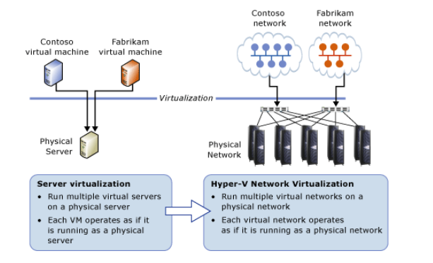
This article builds on the Hyper-V lab environment created throughout my Microsoft Hyper-V Networking Best Practices series, where we deployed a two-node Hyper-V Failover Cluster and gradually introduced the networking, storage, and centralized management components used in our lab.
In particular, in Part 4, we introduced System Center Virtual Machine Manager (SCVMM) and configured centrally managed Logical Networks, Network Sites, Logical Switches, VM Networks, VLANs, and IP address pools. Until now, however, our VM networks have essentially been mapped to the underlying physical VLANs and IP subnets.
In this new series, we take the next step and explore Windows Server Software Defined Networking (SDN) and Hyper-V Network Virtualization (HNV).
The following parts build on this foundation and progressively extend the SDN and HNV environment from basic cross-host tenant connectivity to external routing, overlapping tenant networks, and finally VRF-based multitenant routing.
In Part 2, we will see how HNV provides cross-host connectivity and uses VXLAN encapsulation to transport tenant traffic across the physical Provider Address network.
In Part 3, we will extend the tenant network beyond the HNV fabric using the native Microsoft SDN Gateway and pfSense.
In Part 4, we will introduce a second tenant with an overlapping IP address space, before using Linux VRFs (Virtual Routing and Forwarding) in Part 5 to preserve the separate tenant routing contexts beyond HNV while sharing the same Internet connection.
In Part 6, we will extend the overlapping tenant networks even further by connecting each HNV tenant to a separate Azure Virtual Network (VNet) through its own Site-to-Site IPsec VPN, using XFRM interfaces and Linux VRFs to preserve the individual tenant routing contexts. XFRM interfaces were introduced to overcome design limitations of the existing Linux VTI devices and provide a more flexible interface-based approach for IPsec processing.
- Why are we using Windows Admin Center and PowerShell instead of SCVMM?
- Understanding Hyper-V Network Virtualization (HNV)
- How Hyper-V Network Virtualization Works
- Preparing the Lab for HNVv2
- Deploying the Microsoft Network Controller
- Installing the Network Controller Role
- Installing SDN Express
- Verifying the Existing Hyper-V Cluster and Network Configuration
- Preparing the SDN Express Configuration
- Configuring the Network Controller REST Endpoint
- Validating the SDN Express Configuration
- Deploying the Network Controller with SDN Express
- Configuring Hyper-V Network Virtualization
- Creating a Tenant VM and Connecting It to the HNV Virtual Network
- Starting the Tenant VM and Verifying Provider Address Allocation
- Troubleshooting
- Links
Why are we using Windows Admin Center and PowerShell instead of SCVMM?
The Windows Server SDN infrastructure shown throughout this article is deployed and managed primarily through Windows Admin Center (WAC) and native PowerShell rather than System Center Virtual Machine Manager (SCVMM).
In traditional Microsoft SDN deployments, SCVMM can provide centralized provisioning and management of tenant virtual networks, VM network interfaces, IP addresses, and network policies.
However, this lab uses the newer Windows Server 2025 Failover Clustering-based Network Controller (FCNC) deployment model, which is currently not integrated with SCVMM 2025.
Therefore, we use Windows Admin Center for the supported deployment and configuration workflows and interact directly with the Network Controller where necessary to examine or configure the underlying SDN and HNV mechanisms.
Microsoft’s two Network Controller deployment models
The following table summarizes the main architectural and management differences between the traditional Network Controller deployment model and the new Failover Clustering-based Network Controller (FCNC) introduced with Windows Server 2025.
| Traditional Network Controller Deployment | Windows Server 2025 FCNC Deployment | |
|---|---|---|
| Network Controller placement | Dedicated Network Controller VMs | Runs directly on the Hyper-V hosts as a clustered service |
| High availability | Multiple Network Controller VMs | Windows Server Failover Clustering |
| Service Fabric | Required | Not required |
| Dedicated NC VMs | Required | Not required |
| Infrastructure footprint | Higher | Significantly reduced |
| SCVMM 2025 integration | Supported through the traditional Network Controller/service-template model | Currently not supported |
| PowerShell / REST management | Supported | Supported |
| Primary benefit | Integrated SCVMM SDN management and orchestration | Simplified architecture with fewer infrastructure components |
Official references: Windows Server 2025 Network Controller Failover Clustering documentation and the Microsoft Q&A confirming the current SCVMM limitation.
Understanding Hyper-V Network Virtualization (HNV)
Before configuring Hyper-V Network Virtualization, it is important to understand how HNV separates the network configuration seen by a virtual machine from the physical network used to transport its traffic.
In traditional VLAN-based Hyper-V networking, a VM is ultimately connected to a physical VLAN and IP subnet. With HNV, an additional software-defined virtualization layer is introduced between the VM network and the underlying physical network. This allows the customer/tenant network topology and IP addressing to remain independent of the network used by the Hyper-V hosts to transport the traffic.
Microsoft distinguishes between two important address spaces:
- Customer Address (CA) – the IP address assigned to and visible inside the virtual machine. Different isolated VM Networks can use the same Customer Address ranges without conflicts.
- Provider Address (PA) – an address belonging to the underlying physical/provider network and used to transport the virtualized traffic between Hyper-V hosts.
This separation enables multiple isolated customer networks to operate on the same shared physical infrastructure, including networks with overlapping IP address spaces. Because the VM’s network identity is no longer directly tied to the physical network topology, HNV also provides significantly greater workload mobility across the virtualized infrastructure.
        CUSTOMER / TENANT NETWORKS
        Customer Address (CA) space

 Tenant A                              Tenant B
 10.0.0.10                            10.0.0.10
     │                                    │
     │           HNV Policy               │
     └──────────────┬─────────────────────┘
                    │
          Hyper-V Virtual Switch
                    │
          HNV Network Virtualization
                    │
     CA → Virtual Network → Provider Network
                    │
                    ▼
        PROVIDER / PHYSICAL NETWORK
          Provider Address (PA)
                    │
          ┌─────────┴─────────┐
          │                   │
     Hyper-V Host 01     Hyper-V Host 02
How Hyper-V Network Virtualization Works
HNV separates the Customer Address (CA) used by the virtual machine from the Provider Address (PA) used by the underlying physical network.
Hyper-V maintains the mapping between these two address spaces in software, allowing the physical infrastructure to transport traffic without requiring the customer network topology to be reproduced with physical VLANs.
For example, two isolated tenants can both operate a VM using the address 10.0.0.10. Although the Customer Addresses are identical, HNV associates them with different virtual networks and ensures that traffic remains isolated while being transported across the shared provider network.
Network Virtualization Using NVGRE
Traditionally, HNV can use Network Virtualization using Generic Routing Encapsulation (NVGRE) to encapsulate customer traffic for transport across the provider network. The original packet containing the Customer Addresses is encapsulated inside another packet containing the Provider Addresses, allowing the physical network to route traffic based only on the provider network.
Original VM packet
┌──────────────────────────────────────┐
│ CA Source:      10.0.0.10            │
│ CA Destination: 10.0.0.20            │
│ Tenant Payload                       │
└──────────────────────────────────────┘
                    │
                    ▼ HNV / NVGRE
Encapsulated packet
┌──────────────────────────────────────┐
│ PA Source:      Hyper-V Host 01      │
│ PA Destination: Hyper-V Host 02      │
│ ┌──────────────────────────────────┐ │
│ │ Original CA packet               │ │
│ │ 10.0.0.10 → 10.0.0.20            │ │
│ └──────────────────────────────────┘ │
└──────────────────────────────────────┘
The physical switches and routers therefore only need to understand the Provider Address network. The tenant’s Customer Address network remains virtualized inside HNV, which is what allows overlapping customer address spaces and removes the requirement for a separate physical VLAN for every tenant.
Virtual Subnet IDs (VSIDs)
To distinguish between virtual networks that may use the same Customer Address (CA) space, HNV assigns a Virtual Subnet ID (VSID) to each virtual subnet. The VSID becomes part of the network virtualization information used by HNV, allowing otherwise identical IP packets to be associated with completely different isolated networks.
For example, both tenants could use exactly the same subnet:
Tenant A
Virtual Subnet: 10.0.0.0/24
VSID: 5001
VM: 10.0.0.10

Tenant B
Virtual Subnet: 10.0.0.0/24
VSID: 6001
VM: 10.0.0.10
Although both VMs have the Customer Address 10.0.0.10, HNV can distinguish their traffic because they belong to different VSIDs. From the tenant perspective, each VM simply communicates within its own normal IP network; the additional network identity and isolation are handled transparently by HNV.
With NVGRE, the VSID is carried as part of the GRE encapsulation and identifies the virtual subnet to which the encapsulated packet belongs. This allows many isolated virtual subnets to share the same underlying Provider Address (PA) network without requiring a dedicated physical VLAN for each tenant.
So conceptually we now have:
Tenant A                          Tenant B
CA: 10.0.0.10                    CA: 10.0.0.10
VSID: 5001                       VSID: 6001
      │                                │
      └──────────── HNV ───────────────┘
                     │
              NVGRE Encapsulation
                     │
              Provider Network
                 PA Space
Note: A VSID identifies a virtual subnet, not an individual VM. Multiple VMs within the same virtual subnet therefore use the same VSID while retaining their own unique Customer Addresses.
Transporting HNV Traffic Across the Provider Network
After HNV has identified the appropriate virtual network and virtual subnet, the traffic still needs to be transported between Hyper-V hosts across the underlying Provider Address (PA) network. To achieve this without requiring the physical network to understand the tenant’s Customer Address (CA) topology, HNV uses network virtualization mechanisms that carry the tenant traffic across the shared provider infrastructure.
The original packet containing the Customer Addresses remains associated with its virtual network, while the underlying network transports the traffic using the Provider Addresses of the Hyper-V infrastructure. The physical switches and routers therefore only need connectivity between the provider endpoints and do not need routes for every individual tenant network.
NVGRE and VXLAN Encapsulation
Historically, Hyper-V Network Virtualization used NVGRE (Network Virtualization using Generic Routing Encapsulation). NVGRE encapsulates the original tenant packet inside a GRE packet and uses the VSID to identify the virtual subnet to which the traffic belongs.
Modern Microsoft SDN implementations also support VXLAN (Virtual Extensible LAN). VXLAN follows the same basic overlay principle, encapsulating tenant traffic for transport across an IP-based underlay, but uses a VNI (VXLAN Network Identifier) rather than an NVGRE VSID to identify the virtual network segment.
A simple way to introduce the terminology is:
| HNV / NVGRE | VXLAN | Purpose |
|---|---|---|
| VSID | VNI | Identifies the isolated virtual network segment |
| Customer Address (CA) | Inner/tenant IP | Address used by the VM |
| Provider Address (PA) | Underlay/VTEP-side IP | Address used by the physical/provider network |
| GRE encapsulation | UDP/VXLAN encapsulation | Carries tenant traffic across the provider network |
HNV Packet Encapsulation
              TENANT / CUSTOMER NETWORK
                 Customer Address (CA)

        VM-A                              VM-B
     10.0.0.10                         10.0.0.20
        │                                  ▲
        │ Original tenant packet           │
        │                                  │
        ▼                                  │
┌─────────────────────────────────────────────────────┐
│              Hyper-V Host 01                        │
│                                                     │
│  Original Packet                                    │
│  ┌──────────────────────────────────────────────┐   │
│  │ CA Src: 10.0.0.10                            │   │
│  │ CA Dst: 10.0.0.20                            │   │
│  │ Tenant Payload                               │   │
│  └──────────────────────────────────────────────┘   │
│                         │                           │
│                         ▼ HNV                       │
│                                                     │
│  Encapsulated Packet                                │
│  ┌──────────────────────────────────────────────┐   │
│  │ Outer Header                                 │   │
│  │ PA Src: Hyper-V Host 01                      │   │
│  │ PA Dst: Hyper-V Host 02                      │   │
│  │                                              │   │
│  │ NVGRE: VSID 5001                             │   │
│  │   or                                         │   │
│  │ VXLAN: VNI 5001                              │   │
│  │                                              │   │
│  │ ┌──────────────────────────────────────────┐ │   │
│  │ │ Original Tenant Packet                   │ │   │
│  │ │ CA 10.0.0.10 → 10.0.0.20                 │ │   │
│  │ └──────────────────────────────────────────┘ │   │
│  └──────────────────────────────────────────────┘   │
└────────────────────────┬────────────────────────────┘
                         │
                         │
                         ▼
              PROVIDER / UNDERLAY NETWORK
                   Provider Address (PA)

                 Physical IP Network
                         │
                         ▼
┌─────────────────────────────────────────────────────┐
│              Hyper-V Host 02                        │
│                                                     │
│        HNV removes outer encapsulation              │
│                         │                           │
│                         ▼                           │
│           CA 10.0.0.10 → 10.0.0.20                  │
└─────────────────────────┬───────────────────────────┘
                          │
                          ▼
                       VM-B
                    10.0.0.20
When traffic leaves the source VM, HNV encapsulates the original packet containing the Customer Addresses (CA) inside an outer packet that can be transported across the Provider Address (PA) network. With NVGRE, the virtual subnet is identified by a VSID, while VXLAN uses a VNI. The destination Hyper-V host removes the encapsulation and forwards the original tenant packet to the destination VM.
HNVv1 vs. HNVv2
Microsoft introduced HNVv1 with Windows Server 2012. HNVv1 provided the fundamental concepts we discussed above: Customer Addresses (CA), Provider Addresses (PA), virtual network isolation, overlapping tenant IP spaces, and NVGRE-based network virtualization.
Its configuration was primarily based on WMI and PowerShell, with SCVMM providing centralized management. Microsoft states that HNVv1 received no additional features beginning with Windows Server 2016 and that no new features are planned.
With Windows Server 2016, Microsoft introduced HNVv2 as part of a much broader Software Defined Networking (SDN) architecture. Instead of individual hosts simply maintaining HNV policies, a network policy is centrally defined by the Microsoft Network Controller, distributed to the SDN Host Agents, and finally programmed into the Virtual Filtering Platform (VFP) extension inside the Hyper-V Virtual Switch.
Conceptually, the architecture changes from:
HNVv1

SCVMM / PowerShell
        │
        ▼
   Hyper-V Host
        │
   HNV Policies
        │
      NVGRE
        │
        ▼
 Provider Network
to:
For this lab and throughout the following series, we use VXLAN as the HNV overlay encapsulation rather than NVGRE (Network Virtualization using Generic Routing Encapsulation).
GRE (Generic Routing Encapsulation) is a general-purpose tunneling protocol used to encapsulate traffic across an IP network. NVGRE builds on GRE specifically for network virtualization, using the GRE Key field to carry a 24-bit Virtual Subnet ID (VSID) that identifies the isolated virtual network to which the encapsulated tenant traffic belongs.
In Part 2, we will verify this directly with a packet capture showing the VXLAN-encapsulated tenant traffic and its VNI between the Hyper-V hosts.
HNVv2 / Microsoft SDN

        SCVMM / PowerShell / REST
                  │
                  ▼
          Network Controller
            (Control Plane)
                  │
          Network Policies
                  │
                  ▼
            SDN Host Agent
                  │
                  ▼
       Hyper-V Virtual Switch
                  │
                  VFP
            (Data Plane)
                  │
          HNV / Overlay
          NVGRE or VXLAN
                  │
                  ▼
          Provider Network
The Virtual Filtering Platform (VFP) is particularly important in HNVv2. It is the programmable forwarding extension within the Hyper-V switch that enforces policies received from the Network Controller, including CA-to-PA mappings, forwarding rules, ACLs, QoS and other SDN policies. Microsoft describes HNVv2 as being implemented using the same Azure-derived VFP technology.
Interestingly, HNV shares architectural concepts with Microsoft Azure networking. HNV uses Microsoft’s Virtual Filtering Platform (VFP) in the Hyper-V switch for network virtualization, including CA-to-PA mappings and overlay encapsulation, while VFP was originally developed to power Azure’s host-based SDN dataplane.
Azure applies the same broader principle, decoupling customer virtual networks from the physical fabric, but with its own hyperscale control plane, dataplane and hardware offloading.
| HNVv1 | HNVv2 | |
|---|---|---|
| Introduced | Windows Server 2012 | Windows Server 2016 |
| Architecture | Host-centric HNV | Full Microsoft SDN stack |
| Central control plane | SCVMM / PowerShell management | Network Controller |
| Data plane | HNV implementation in Hyper-V | VFP in Hyper-V Switch |
| Encapsulation | Primarily NVGRE | NVGRE and VXLAN |
| Policy distribution | WMI / PowerShell / SCVMM | Network Controller → Host Agent → VFP |
| ACL / QoS integration | More limited | Integrated SDN policy |
| SET support | Not compatible with HNVv1 | Designed for modern SDN/SET architecture |
| Development status | Legacy / no new features planned | Modern HNV architecture |
Microsoft specifically notes that HNVv1 and Switch Embedded Teaming (SET) aren’t compatible. This matters considerably for our lab because we built our Hyper-V networking around SET in the previous parts of this series.
HNVv2, together with the Network Controller and VFP, is therefore the architecture relevant to the modern environment we are building.
Note: HNVv2 should not be thought of as simply “HNVv1 but with VXLAN.” The major change is architectural: HNV became part of Microsoft’s broader SDN stack, with a centralized Network Controller providing the control plane and VFP providing the programmable data plane on each Hyper-V host.
So with HNVv2 / the modern Microsoft SDN stack, we can and should continue using a SET-based Hyper-V virtual switch.
Microsoft explicitly describes SET as suitable for environments using Hyper-V with the SDN stack.
In fact, Microsoft’s HNVv2 documentation goes further: HNVv2 uses one Provider Address (PA) per SET team member.
Microsoft even describes the typical deployment as a two-NIC SET team with two PA addresses per Hyper-V host.
For our lab, this means we do not have to tear down the SET vSwitches we built earlier. Instead, the HNVv2/SDN components, Network Controller, Host Agent and VFP, add the software-defined networking functionality to the Hyper-V networking stack.
Microsoft also recommends SET when physical NIC teaming is used with SDN.
Note: Unlike HNVv1, which is not compatible with Switch Embedded Teaming (SET), HNVv2 is designed to integrate with the modern Hyper-V SDN stack and SET. Therefore, the SET-based virtual switches configured in the previous parts of this series can continue to be used when implementing HNVv2.
GRE vs. NVGRE
For this lab and throughout the following series, we use VXLAN, which became available with HNVv2, rather than NVGRE.
HNVv2 supports both NVGRE and VXLAN, while HNVv1 originally used NVGRE for overlay encapsulation.
GRE (Generic Routing Encapsulation) is a general-purpose tunneling protocol that encapsulates one network protocol inside another for transport across an IP network.
Generic Routing Encapsulation (GRE) is a method of tunneling traffic between two endpoints without encryption. It can be used to route packets between two locations that are not directly connected, which do not require encryption. It can also be combined with a method of encryption that does not perform its own tunneling.
Source: https://docs.netgate.com/pfsense/en/latest/interfaces/gre.html
GRE itself does not provide the tenant-aware network virtualization required by HNV.
NVGRE (Network Virtualization using Generic Routing Encapsulation) builds on GRE specifically for network virtualization. It uses the 24-bit GRE Key field as the Virtual Subnet ID (VSID), allowing HNV to identify the isolated virtual subnet to which an encapsulated tenant packet belongs.
Hyper-V supports network virtualization using generic routing encapsulation (NVGRE) as the mechanism to virtualize IP addresses. In NVGRE, the virtual machine’s packet is encapsulated inside another packet. The header of this new, NVGRE-formatted packet has the appropriate source and destination provider area (PA) IP addresses. In addition, it has a 24-bit Virtual Subnet ID (VSID), which is stored in the GRE header of the new packet.
This makes NVGRE conceptually similar to VXLAN: NVGRE uses a VSID carried in GRE, whereas VXLAN uses a VNI carried in the VXLAN header over UDP. Both provide an overlay that separates the tenant/customer address space from the underlying provider network.
When HNVv1 was introduced with Windows Server 2012, VXLAN had only recently been introduced in 2011 and had not yet been standardized as an IETF RFC. Microsoft therefore based HNVv1 on NVGRE, while VXLAN support was introduced later with HNVv2.
GRE vs. ESP
ESP is not used for the HNV overlay itself in this lab; it is included here only to distinguish its security-focused purpose from GRE. ESP becomes relevant later in Part 6, where we use IPsec for the Site-to-Site VPN connections to Azure.
Although GRE and ESP (Encapsulating Security Payload) both encapsulate traffic, they serve very different purposes. GRE is a general-purpose tunneling protocol and does not provide encryption by itself, whereas ESP is part of IPsec and is designed to securely transport traffic by providing encryption, integrity, authentication, and anti-replay protection.
In an IPsec Site-to-Site VPN, IKE/IKEv2 negotiates the security associations (SAs), while ESP carries and protects the actual data traffic. When NAT Traversal (NAT-T) is required, ESP is additionally encapsulated in UDP/4500, as used by the Site-to-Site VPNs later in this series in Part 6.
Long-time Windows administrators will probably recognize PPTP from the built-in Windows VPN client.
PPTP uses an enhanced form of GRE (IP protocol 47) to carry the encapsulated PPP traffic, while GRE itself provides no encryption.
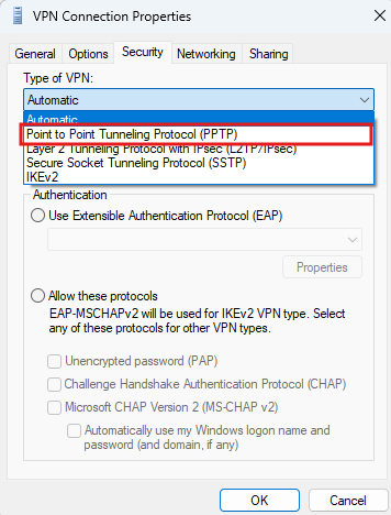
PPTP itself consists of several components working together. A TCP connection on port 1723 is used for PPTP tunnel control and management, while GRE (IP protocol 47) transports the encapsulated PPP frames carrying the actual user traffic.
Authentication is typically performed within PPP using protocols such as MS-CHAPv2, while MPPE (Microsoft Point-to-Point Encryption) provides encryption of the PPP payload.
GRE therefore provides the transport tunnel but does not provide encryption itself.
Today, PPTP should be considered a legacy VPN technology and Microsoft has deprecated it in favor of more modern alternatives such as IKEv2. In particular, authentication schemes historically associated with PPTP, such as MS-CHAPv2, have well-documented cryptographic weaknesses and should no longer be relied upon for modern VPN deployments.
Beyond PPTP, GRE is commonly used for router-to-router tunnels, allowing networks or routing protocols to be transported across an intermediate IP network.
It can also be combined with IPsec, where GRE provides the tunneling functionality while IPsec provides encryption and authentication.
Technologies such as Cisco DMVPN use multipoint GRE (mGRE) to dynamically connect multiple sites, while NVGRE adapts GRE for network virtualization by using the GRE Key field to carry the Virtual Subnet ID (VSID).
Network Controller and the HNVv2 Control Plane
With HNVv2, network virtualization becomes part of Microsoft’s broader Software Defined Networking (SDN) architecture. Instead of configuring the required network virtualization information independently on each Hyper-V host, the environment is centrally controlled by the Network Controller.
The Network Controller maintains the desired network configuration and communicates this information to the participating Hyper-V hosts. This includes information about virtual networks, virtual subnets, routing, policies, and the mappings between Customer Addresses (CA) and Provider Addresses (PA).
The individual Hyper-V hosts then implement these policies in their Hyper-V Virtual Switch and associated networking stack. This separates the control plane from the actual data plane carrying VM traffic.
                    Network Controller
                    (SDN Control Plane)
                           |
                 Network configuration
                       and policies
                           |
             +-------------+-------------+
             |                           |
       Hyper-V Host 01              Hyper-V Host 02
             |                           |
        SET vSwitch                  SET vSwitch
             |                           |
          VM-A                         VM-B
       CA: 10.0.0.10              CA: 10.0.0.20
             |                           |
             +------ HNV Overlay --------+
                       |
                 Physical Network
                 Provider Network
                    PA addresses
The Microsoft SDN Architecture
Now that we understand the differences between HNVv1 and HNVv2, let us take a broader look at the Microsoft Software Defined Networking (SDN) architecture in which modern Hyper-V Network Virtualization operates.
With HNVv2, network virtualization is no longer just an isolated feature of individual Hyper-V hosts. Instead, it is integrated into an SDN architecture where the control plane is separated from the data plane. The desired network configuration is centrally defined and distributed to the Hyper-V hosts, while the hosts continue to perform the actual forwarding of VM traffic.
The major components of this architecture are:
- Network Controller (NC) – Provides the centralized SDN control plane. It maintains the desired network state and configures the participating Hyper-V hosts and other SDN components accordingly.
- Hyper-V Hosts – Provide the data plane for virtual machine traffic. The Hyper-V Virtual Switch and networking stack enforce the networking policies received from the Network Controller and perform the required HNV processing.
- Hyper-V Network Virtualization (HNV) – Provides the virtual network abstraction that separates the Customer Address (CA) space used by VMs from the underlying Provider Address (PA) network.
- Software Load Balancer (SLB) – Provides software-defined Layer 4 load balancing for workloads. It consists of the SLB Manager functionality integrated with Network Controller and SLB Multiplexer (MUX) instances in the infrastructure.
- RAS Gateway – Provides connectivity between the virtualized tenant networks and networks outside the HNV overlay, for example through site-to-site VPN, GRE, or Layer-3 forwarding.
Conceptually, the architecture looks like this:
                         +----------------------+
                         |  Network Controller  |
                         |     Control Plane    |
                         +----------+-----------+
                                    |
                       Network configuration
                         and SDN policies
                                    |
                 +------------------+------------------+
                 |                                     |
        +--------v---------+                  +--------v---------+
        | Hyper-V Host 01  |                  | Hyper-V Host 02  |
        |                  |                  |                  |
        | Hyper-V vSwitch  |                  | Hyper-V vSwitch  |
        |      + HNV       |                  |      + HNV       |
        +--------+---------+                  +--------+---------+
                 |                                     |
              Tenant VM                             Tenant VM
                 |                                     |
                 +----------- HNV Overlay -------------+
                                    |
                         Provider / Physical
                              Network
                                    |
                  +-----------------+----------------+
                  |                                  |
             +----v------+                     +-----v------+
             | RAS       |                     | SLB MUX    |
             | Gateway   |                     |            |
             +-----------+                     +------------+
                  |
            External Networks
The important point is that Network Controller normally does not sit in the forwarding path of every packet. It represents the control plane: it tells the participating components how traffic should be handled. The Hyper-V hosts, gateways, and SLB infrastructure form the data plane and actually process and forward the traffic.
This is conceptually similar to other SDN platforms: instead of manually configuring networking independently on every virtualization host, we describe the desired logical network state, while the SDN infrastructure translates that state into the configuration required on the underlying physical infrastructure.
In our lab, the SET-based Hyper-V virtual switch created earlier can continue to provide the underlying host connectivity. HNVv2 and the Microsoft SDN components add the network virtualization and policy layer rather than replacing the physical networking foundation we already built.
Preparing the Lab for HNVv2
Before deploying HNVv2, we first need to prepare the required Microsoft SDN infrastructure. Our existing Hyper-V cluster and SET-based virtual switches can remain in place, while the main additional component required for HNVv2 is the Microsoft Network Controller, which provides the centralized SDN control plane.
Because our Hyper-V hosts are running Windows Server 2025, Microsoft now gives us two ways to deploy Network Controller:
- The traditional Service Fabric / Network Controller VM deployment, which is also the deployment model documented for integration with SCVMM. VMM uses a Network Controller service template, prepared VHDX, certificates, AD groups, management logical network, and other supporting resources.
- Beginning with Windows Server 2025, Network Controller can instead run directly on the Hyper-V hosts as a Failover Clustering service. This eliminates the separate Network Controller VM infrastructure and is specifically intended to reduce the infrastructure footprint.
For our small two-node lab, that new Windows Server 2025 approach is obviously very attractive:
Matrix-HV-Cluster
│
├── Matrix-HV-01
│   ├── Hyper-V
│   ├── SET vSwitch
│   └── Network Controller role
│
├── Matrix-HV-02
│   ├── Hyper-V
│   ├── SET vSwitch
│   └── Network Controller role
│
└── Network Controller
    └── Highly available clustered service
Before proceeding with the HNVv2 configuration, we will first upgrade our existing System Center Virtual Machine Manager (SCVMM) 2022 installation to SCVMM 2025. This provides native support for managing our Windows Server 2025 Hyper-V hosts and brings our existing virtualization management platform to the current System Center 2025 release.
At the time of writing, the Microsoft AI Cloud Partner Program benefits still provide System Center Standard 2022, while the Windows Server benefits have already been updated to Windows Server 2025. Microsoft has therefore not yet rolled out System Center 2025 through these Partner Center benefits.
For our lab, we will therefore temporarily use the System Center 2025 Evaluation, which includes System Center Virtual Machine Manager 2025 and provides the full-featured software for a 180-day evaluation period without requiring a product key.
Download System Center 2025 Evaluation
Although SCVMM 2025 can deploy and manage Microsoft SDN using the traditional Service Fabric-based Network Controller VM architecture, this requires dedicated Network Controller VMs and the corresponding VMM service templates.
For our Windows Server 2025 lab, we will instead use the new Failover Clustering-based Network Controller, which runs directly on our Hyper-V cluster nodes. Therefore, SCVMM service templates are not required for the Network Controller deployment in this article.
Note: In this lab, Network Controller is deployed using the new Windows Server 2025 Failover Clustering-based Network Controller (FCNC) architecture.
At the time of writing, SCVMM 2025 does not provide management integration for this new host-native Network Controller deployment model.
Therefore, the HNV resources and tenant network interfaces in this example are configured directly through Network Controller PowerShell/REST APIs.
SCVMM’s integrated SDN management currently applies to the traditional Network Controller deployment model based on Network Controller VMs and VMM service templates.
Upgrading SCVMM 2022 to SCVMM 2025
To upgrade System Center Virtual Machine Manager (SCVMM) 2022 to SCVMM 2025, we first need to uninstall the existing SCVMM 2022 installation while retaining the VMM database.
We can then install SCVMM 2025 and reconnect it to the existing database, preserving the current VMM configuration.
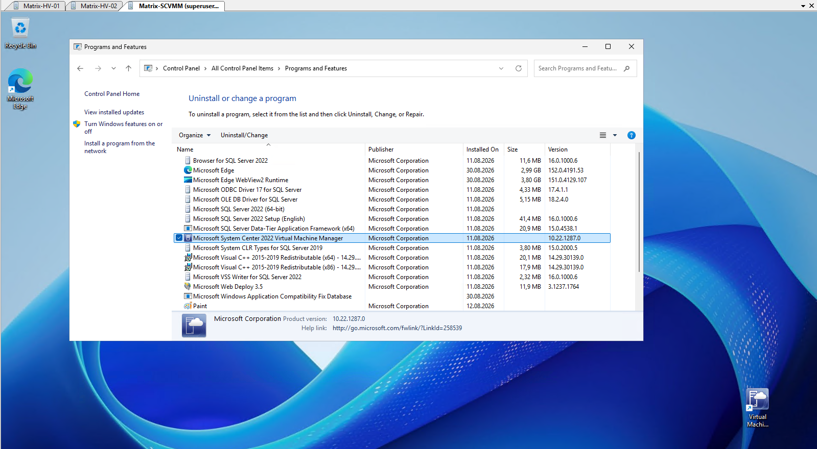
Open Control Panel → Programs and Features, select the existing Microsoft System Center 2022 Virtual Machine Manager installation, and click Uninstall/Change.
This launches the VMM Setup wizard, where we can remove the existing SCVMM 2022 installation while retaining its configuration database for the subsequent SCVMM 2025 installation.
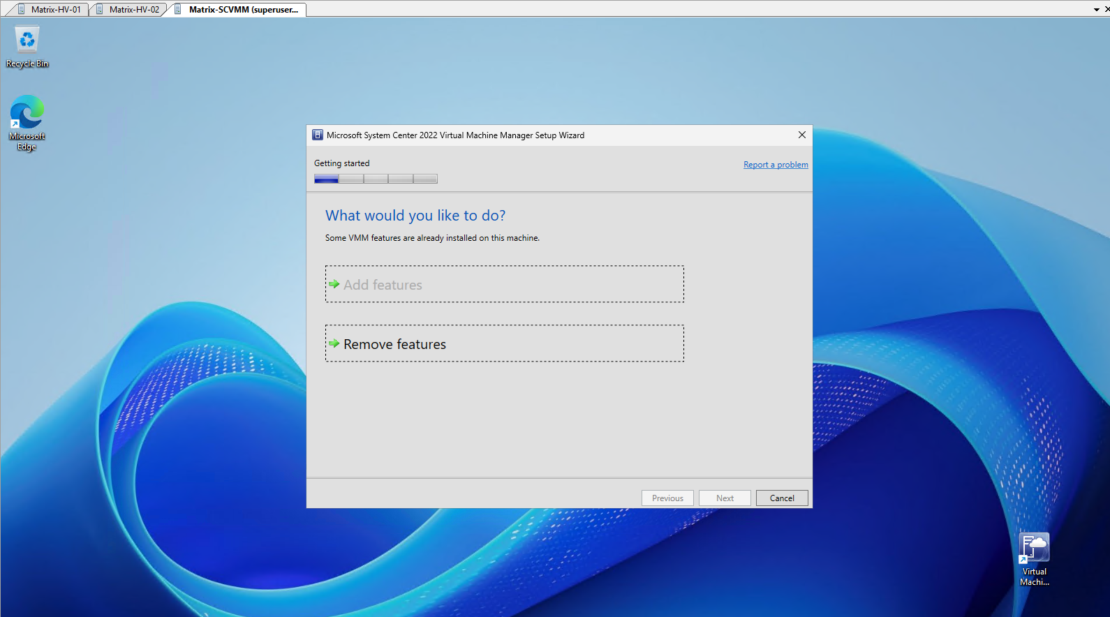
In the System Center 2022 Virtual Machine Manager Setup Wizard, select Remove features to begin uninstalling the existing SCVMM 2022 components.
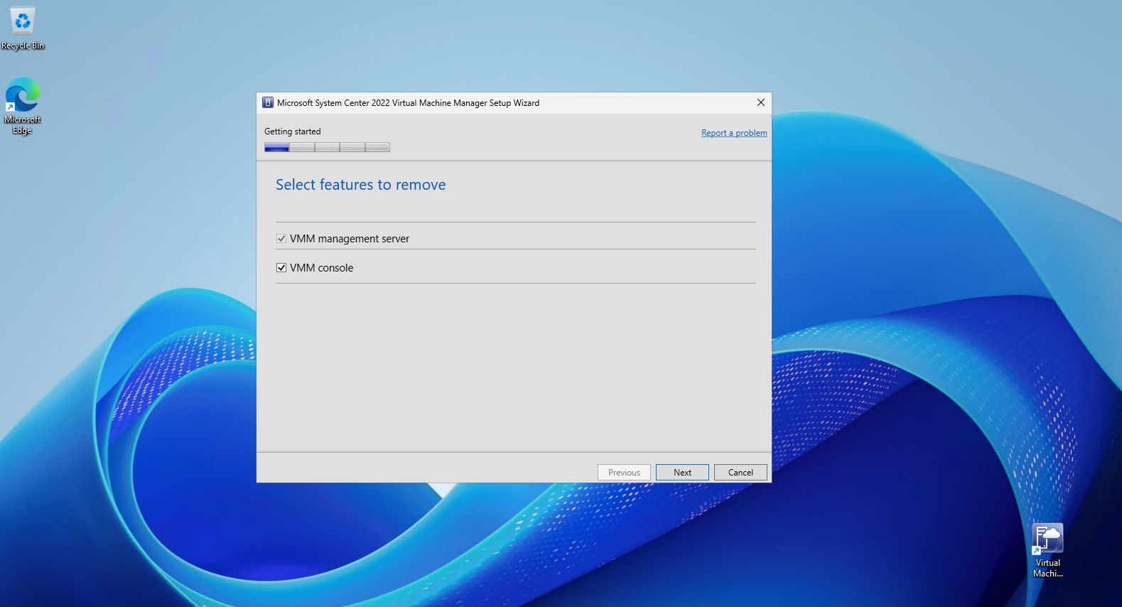
Select both the VMM management server and VMM console features for removal.
Removing these components does not require deleting the existing VMM database, which we will retain and reuse during the SCVMM 2025 installation.
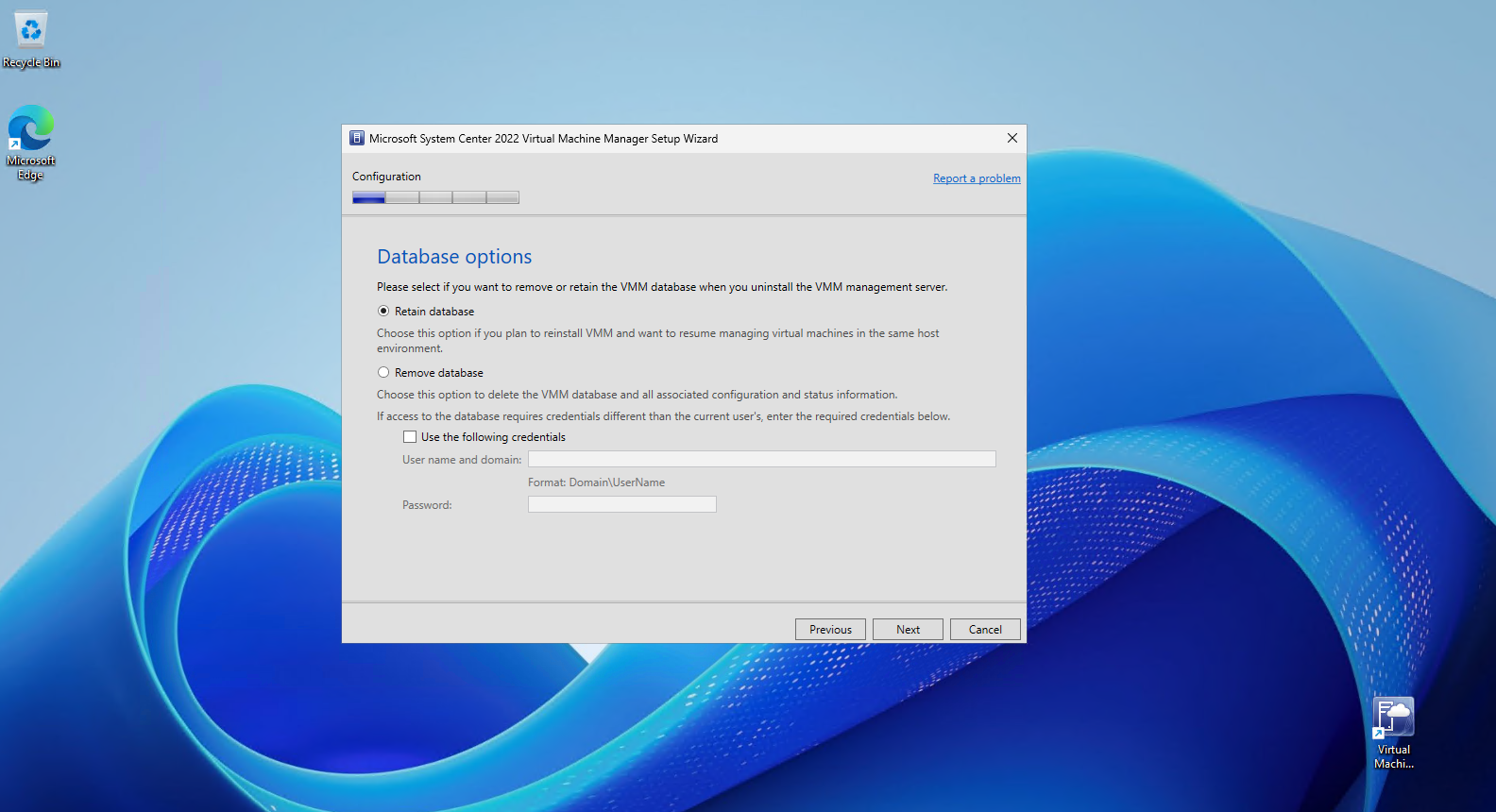
On the Database options page, select Retain database.
This preserves the existing VMM configuration and status information so that the database can be reused when installing SCVMM 2025 and the existing Hyper-V environment can continue to be managed.
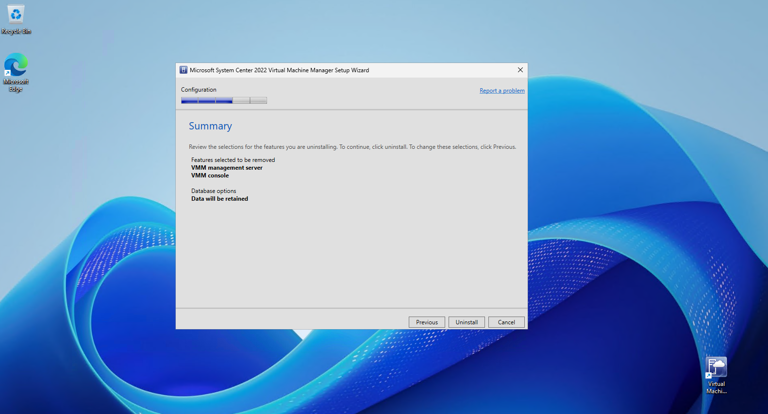
Before starting the uninstall, verify that both the VMM management server and VMM console are selected for removal and, most importantly, that Data will be retained is shown under Database options. Click Uninstall to remove SCVMM 2022 while preserving the existing VMM database for the subsequent upgrade.
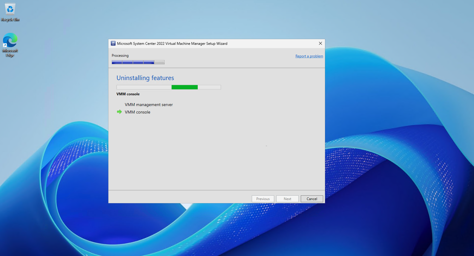
The setup wizard now removes the VMM management server and VMM console components.
The previously retained VMM database remains untouched and will be reused during the installation of SCVMM 2025.
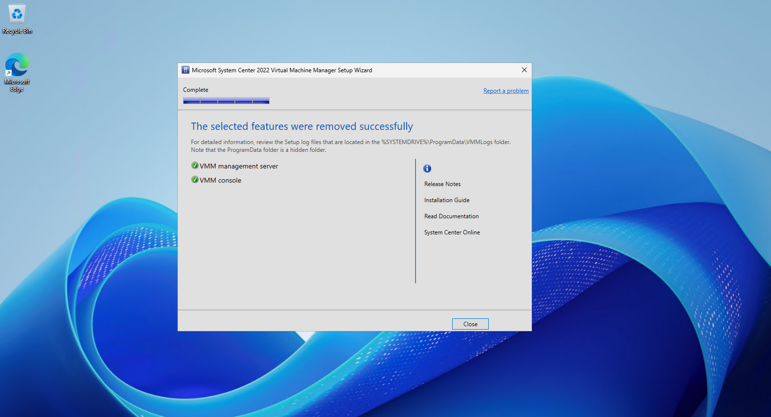
The VMM management server and VMM console have now been successfully removed.
With the existing VMM database retained, we can proceed with installing System Center Virtual Machine Manager 2025 and reconnect it to the existing configuration.
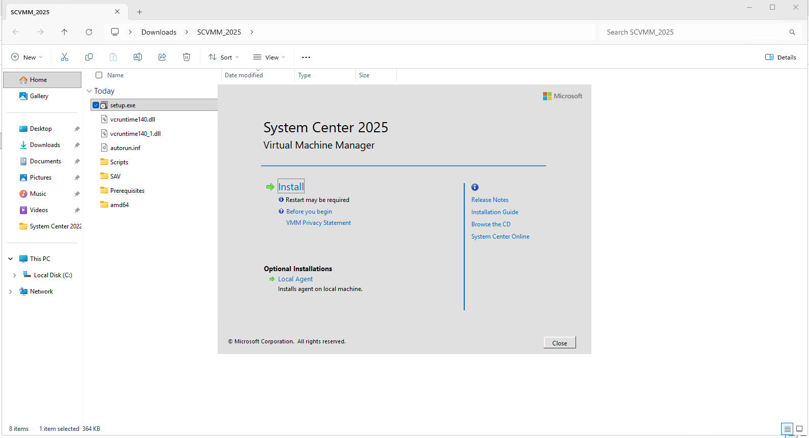
We now run the System Center 2025 Virtual Machine Manager installer and click Install to start the installation of SCVMM 2025.
In the following steps, we will reconnect the new installation to our existing VMM database retained from SCVMM 2022.
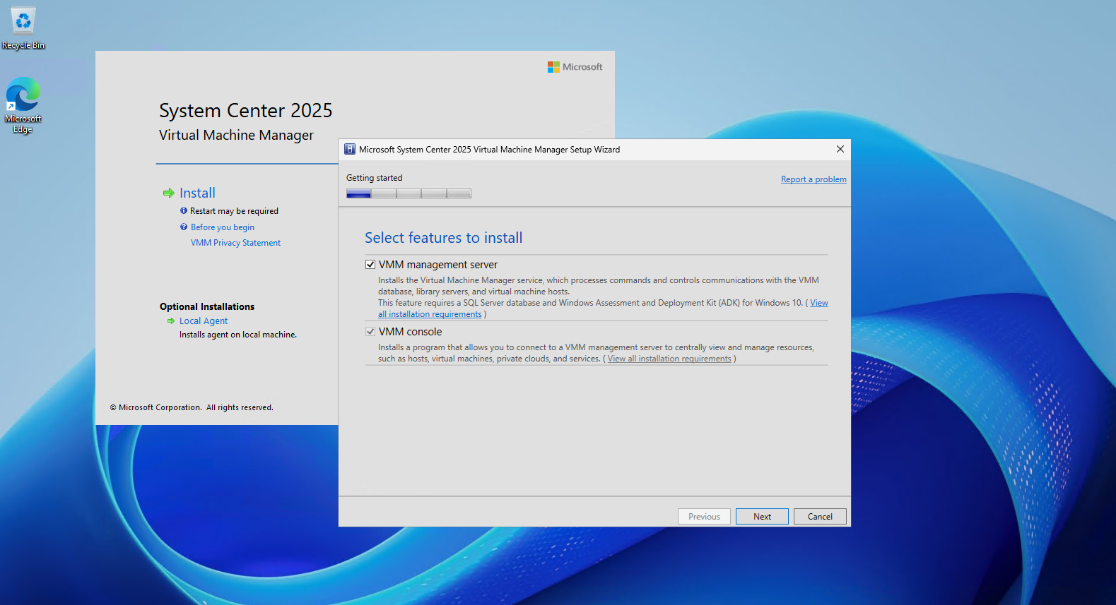
Next, we select the VMM management server feature, which automatically includes the VMM console.
This installs the central Virtual Machine Manager service together with the management console used to administer our Hyper-V infrastructure.
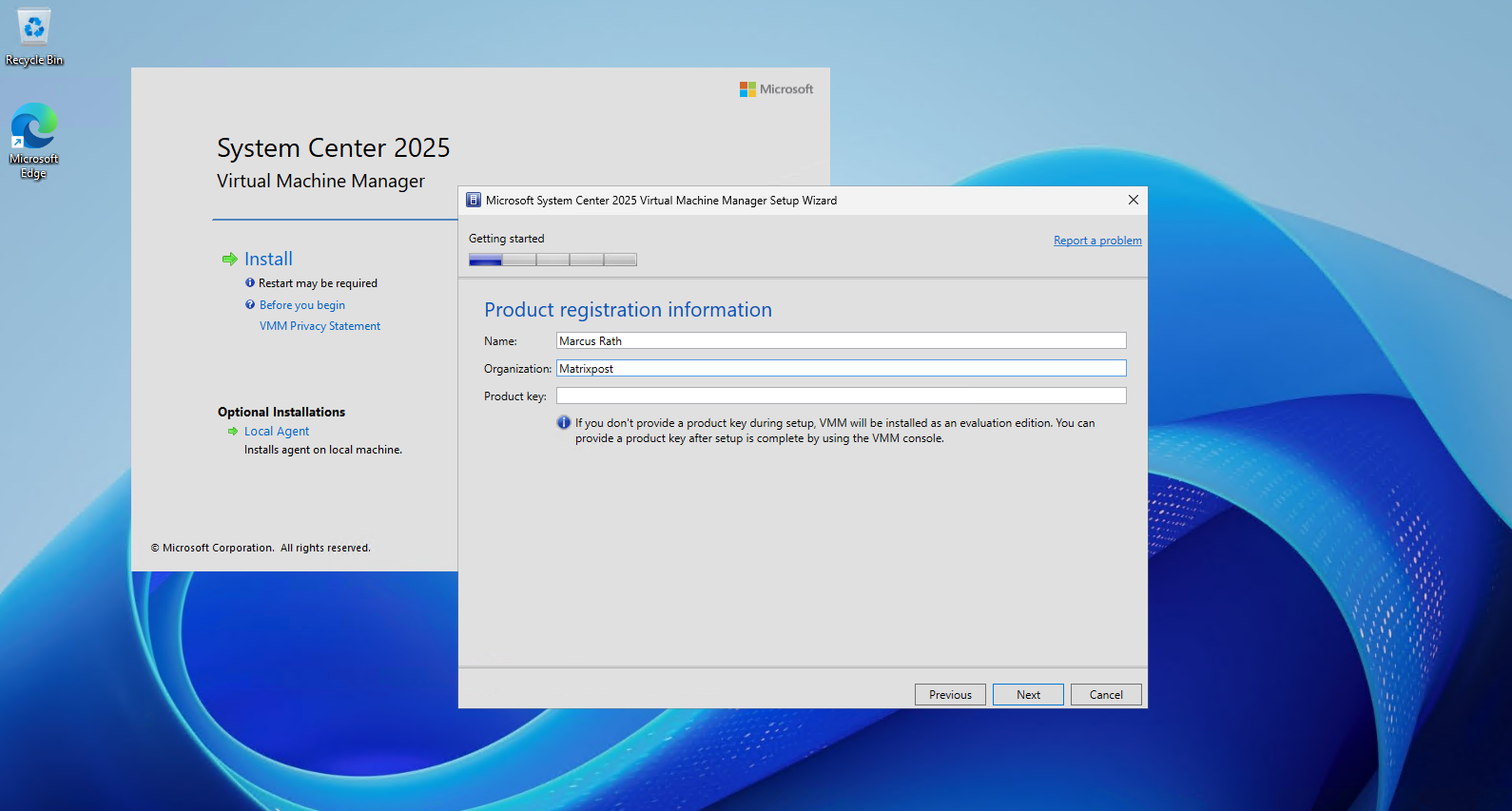
Enter the name and organization for the product registration.
Since we are using the System Center 2025 Evaluation, we leave the Product key field empty; VMM will then be installed as an evaluation edition, and a product key can also be added later through the VMM console.
We keep the default installation location for the VMM program files and click Next to continue.
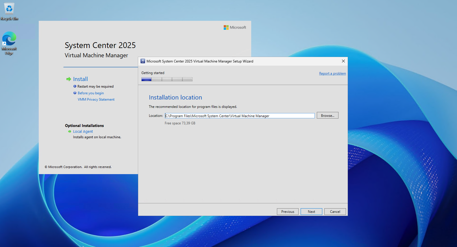
The prerequisite check reports two warnings: the VM currently has only 8 GB of RAM, while 16 GB is recommended for the VMM management server, and a pending restart is detected.
For our lab, the memory warning can be accepted, while we should restart the server before continuing with the installation.
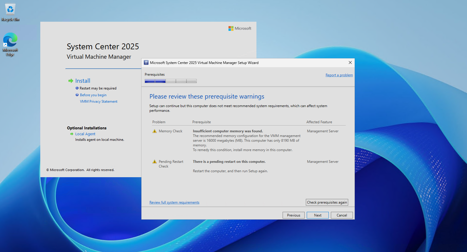
After restarting the server, we run the prerequisite check again.
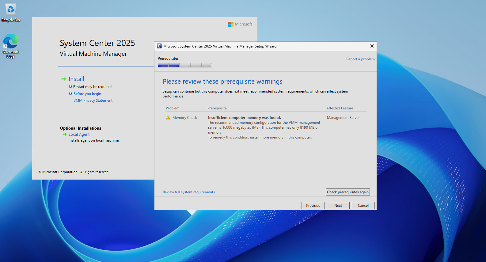
The pending restart warning has disappeared, leaving only the memory recommendation; since 8 GB is sufficient for our small lab environment, we accept this warning and continue with Next.
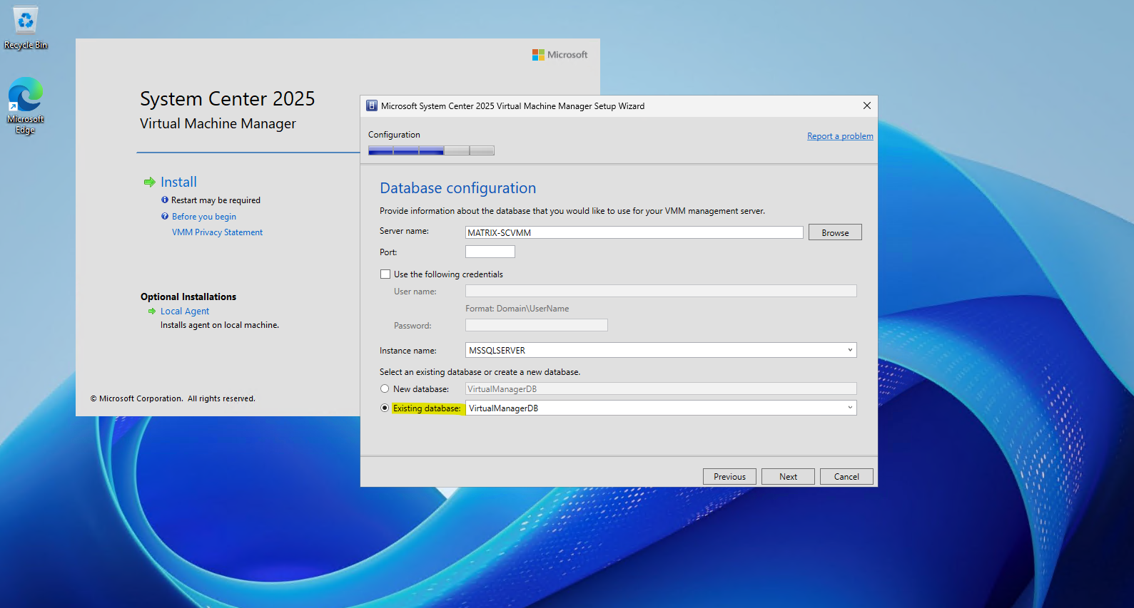
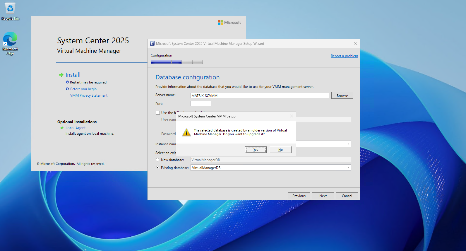
On the Database configuration page, we select the existing VirtualManagerDB database that was retained during the removal of SCVMM 2022.
The remaining SQL Server settings are unchanged from our original installation in Part 4; the important difference is that we select Existing database instead of creating a new one, allowing SCVMM 2025 to upgrade and reuse our existing VMM configuration.
After selecting the existing database, Setup detects that VirtualManagerDB was created by an older version of Virtual Machine Manager and prompts us to upgrade it. We click Yes to allow SCVMM 2025 to upgrade the existing SCVMM 2022 database.
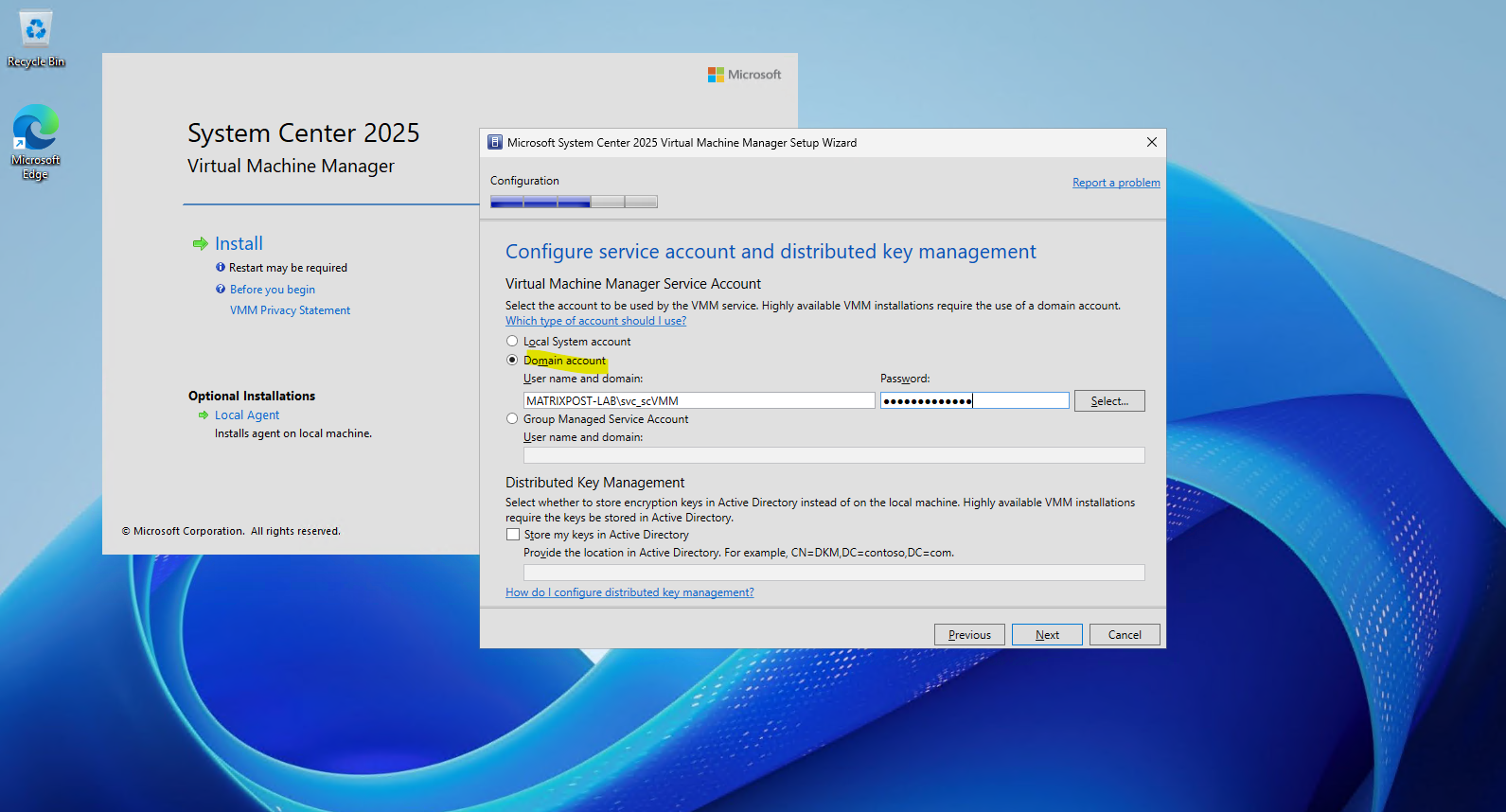
As with our original SCVMM 2022 installation in Part 4, we configure the dedicated domain service account MATRIXPOST-LAB\svc_scVMM for the VMM service.
Since this is a standalone VMM management server, we continue without Distributed Key Management (DKM) and leave the encryption keys stored locally.
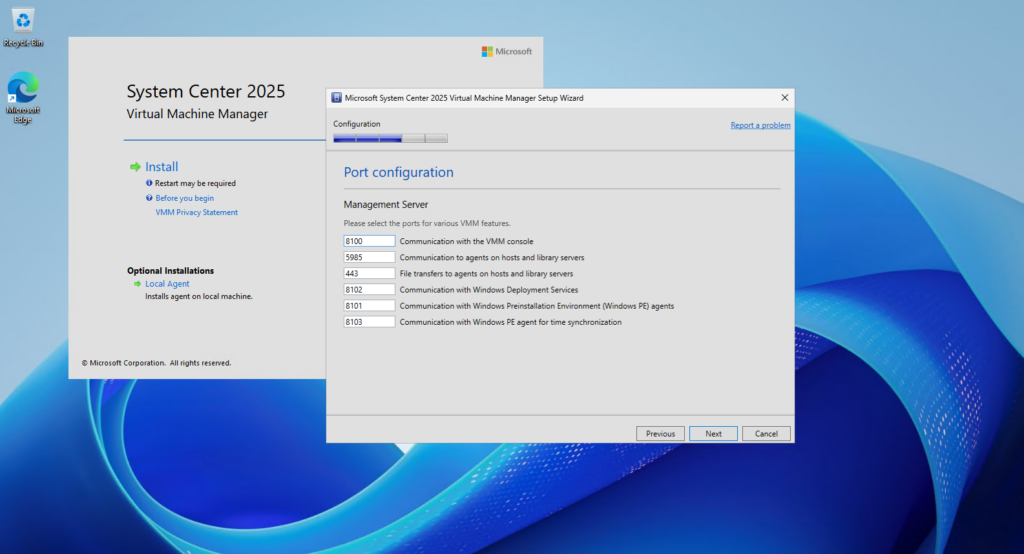
On the Port configuration page, we keep the default VMM communication ports, which are unchanged from our previous SCVMM 2022 installation. Since no custom ports are required in our lab, we leave the defaults and click Next.
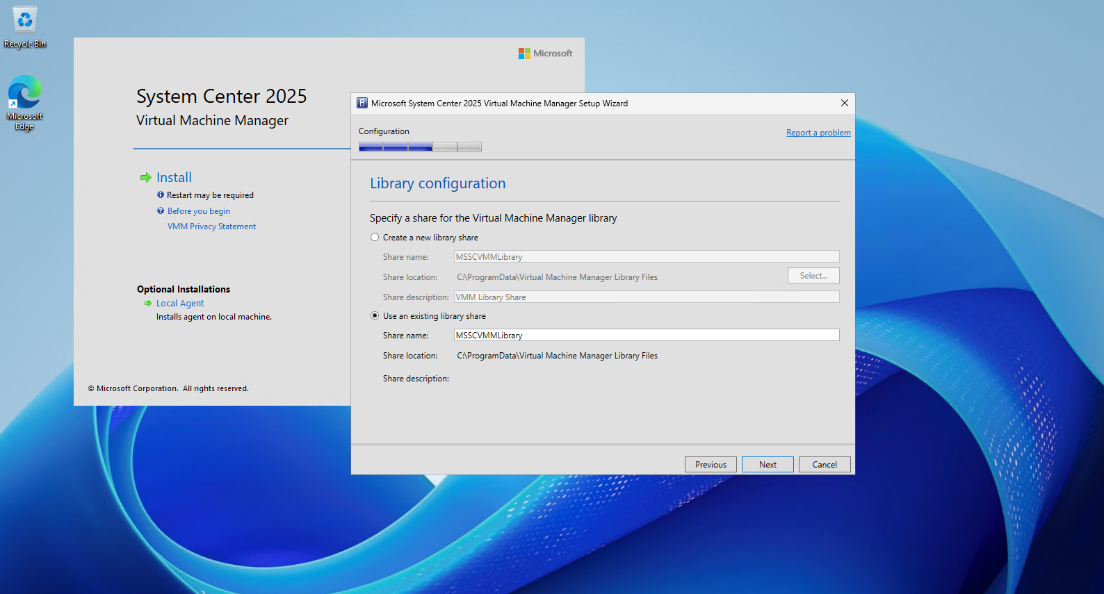
On the Library configuration page, Setup detects the existing MSSCVMMLibrary share from our previous SCVMM 2022 installation. We select Use an existing library share to preserve and reuse the existing VMM library instead of creating a new one.
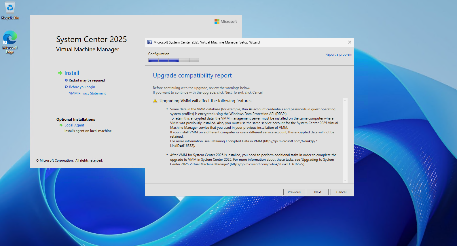
Before continuing, Setup displays the Upgrade compatibility report.
Most importantly, it warns that DPAPI-encrypted VMM data can only be retained when VMM 2025 is installed on the same computer and uses the same VMM service account as before, which is exactly why we reused our existing
MATRIXPOST-LAB\svc_scVMMaccount. Setup also notes that some additional post-upgrade tasks will be required after the installation completes.
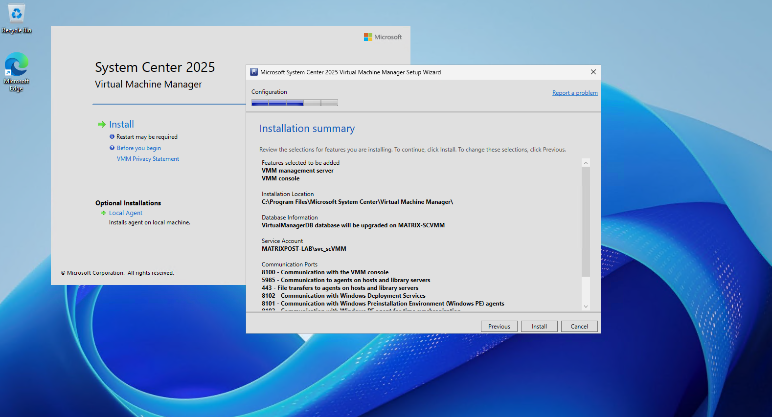
The Installation summary confirms our configuration before starting the upgrade, including the VMM management server and console, the existing VirtualManagerDB database that will be upgraded, the reused VMM service account, and the configured communication ports. After verifying the settings, we click Install to begin the SCVMM 2025 installation and database upgrade.
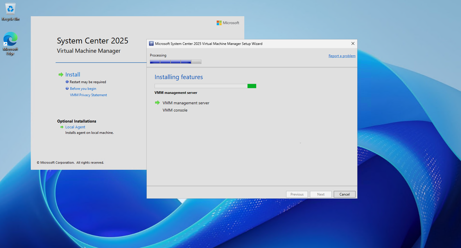
Setup now installs the VMM management server and VMM console and performs the required upgrade of the existing VMM database. Depending on the system, this process may take several minutes to complete.
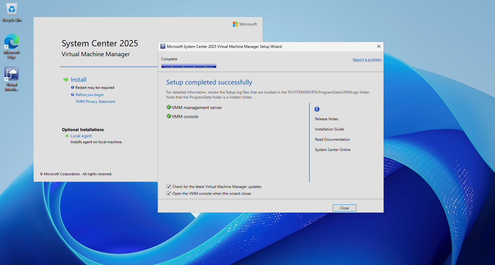
The SCVMM 2025 installation and database upgrade complete successfully, including both the VMM management server and VMM console.
We leave Open the VMM console when this wizard closes selected so we can immediately verify that our existing SCVMM configuration was preserved during the upgrade.
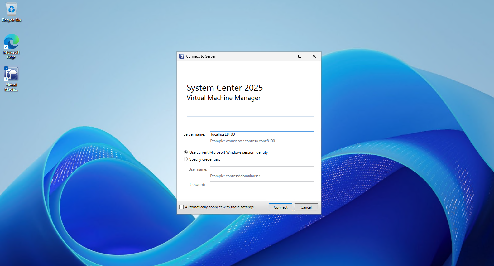
After completing the upgrade, the System Center 2025 Virtual Machine Manager console starts and prompts us to connect to the VMM management server.
Since the console is running directly on our VMM server, we keep
localhost:8100and Use current Microsoft Windows session identity, and then click Connect.
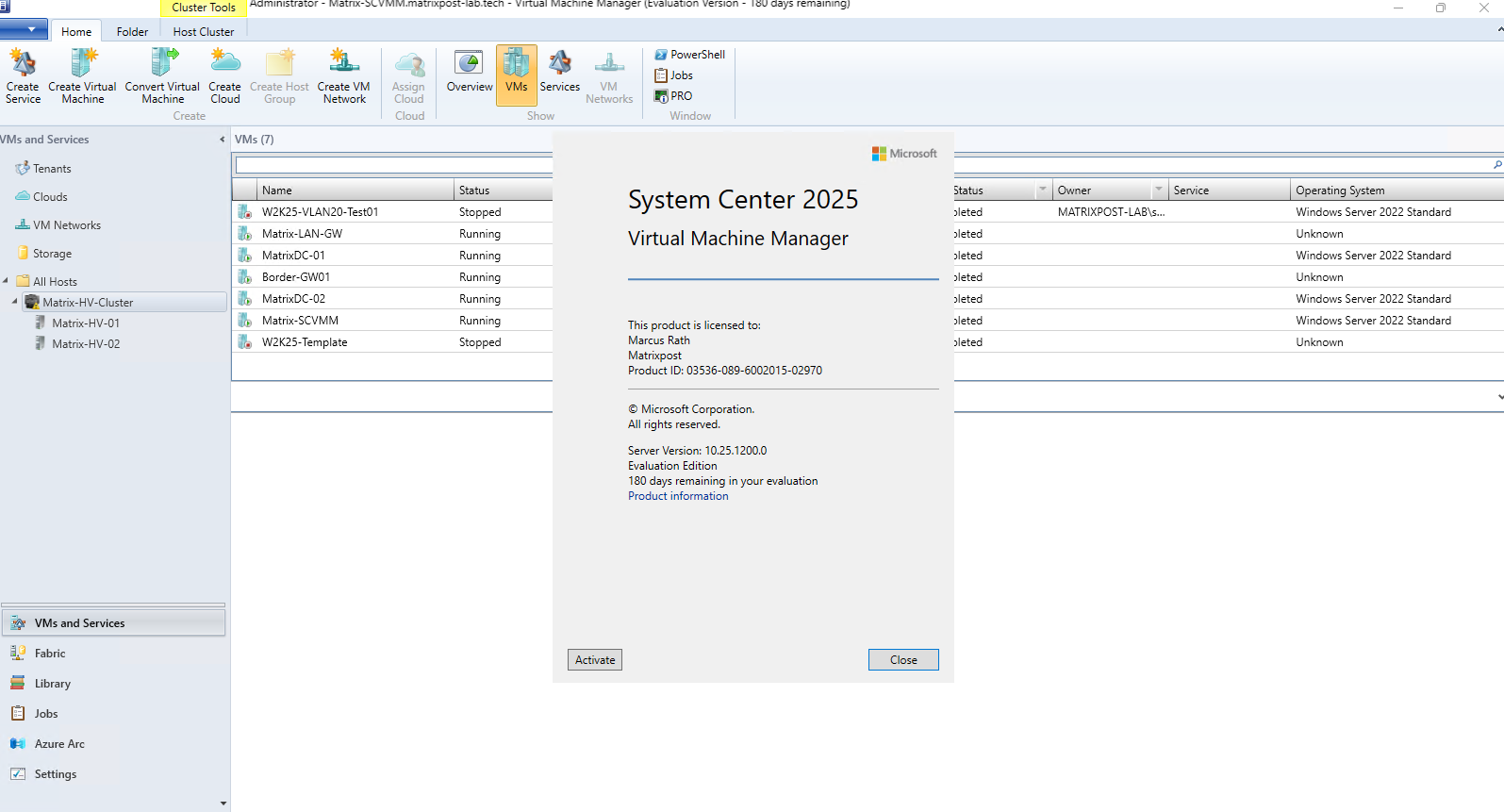
After connecting successfully, we can verify that System Center Virtual Machine Manager 2025 is running as the Evaluation Edition, with the full 180-day evaluation period available.
More importantly, our existing Hyper-V cluster, hosts, virtual machines, and VMM configuration are still present, confirming that the upgrade from SCVMM 2022 to SCVMM 2025 was successful.
Visually, however, SCVMM 2025 remains almost indistinguishable from SCVMM 2022. While the underlying platform continues to evolve, the classic VMM console clearly did not receive the same modernization treatment.
Deploying the Microsoft Network Controller
This is where we move from the upgraded Windows Server 2025 + SCVMM 2025 management stack to the actual HNVv2/SDN infrastructure. The Network Controller provides the centralized control plane that manages and distributes the network policies enforced on our Hyper-V hosts.
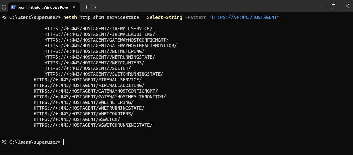
Note: As part of the Microsoft SDN architecture, the Network Controller Host Agent (
NcHostAgent) runs on each Hyper-V host and provides the host-side communication interface between the Network Controller control plane and the SDN components on the host. The Host Agent registers several HTTPS endpoints through HTTP.sys on TCP port 443, including endpoints for the virtual switch, virtual networks, firewall, and gateway functionality.Therefore, TCP port 443 is already used on an SDN-enabled Hyper-V host, which must be considered when installing additional management services such as Windows Admin Center directly on the host.
The output confirms that the Network Controller Host Agent registers multiple SDN-related HTTPS endpoints through HTTP.sys on TCP port 443, including services for virtual networks, the virtual switch, firewall, and gateway functionality.
netsh http show servicestate | Select-String -Pattern "HTTPS://\+:443/HOSTAGENT"
Installing the Network Controller Role
Before deploying the Network Controller as a Failover Clustering service, the Network Controller server role must be installed on every Hyper-V cluster node. Microsoft also requires the corresponding Remote Server Administration Tools (RSAT) and a restart of each node before proceeding with the deployment.
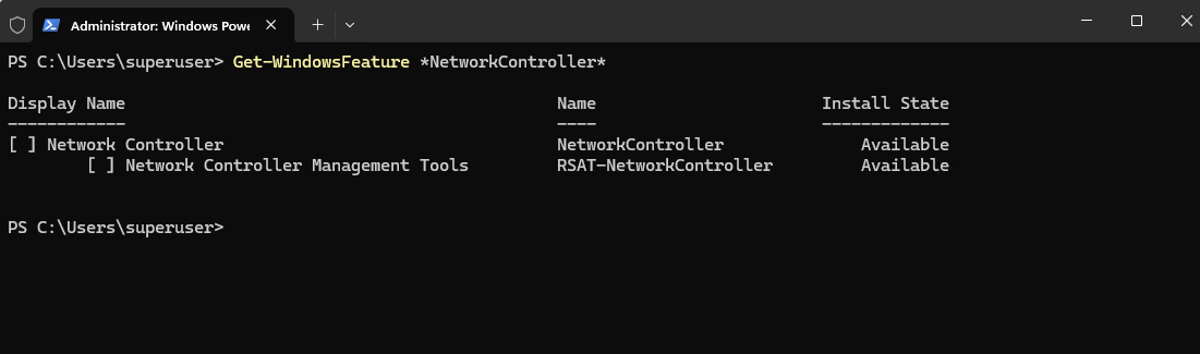
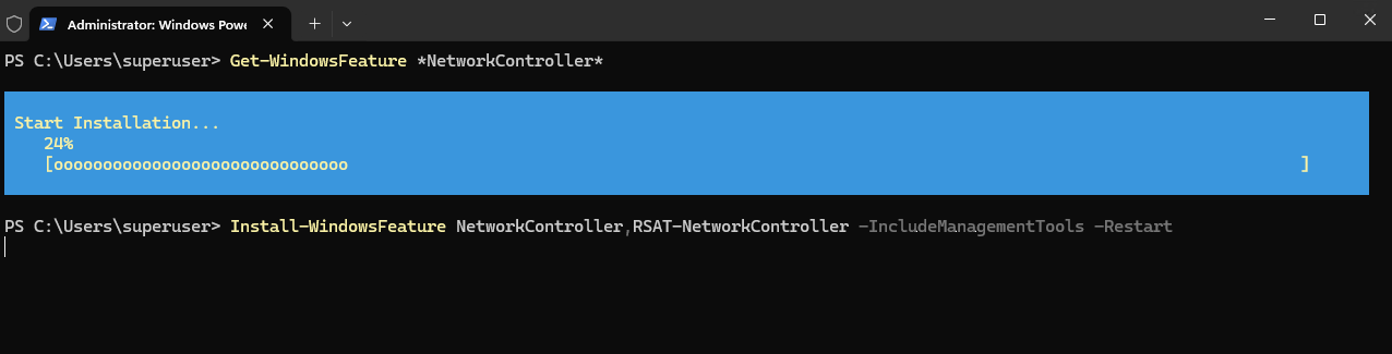
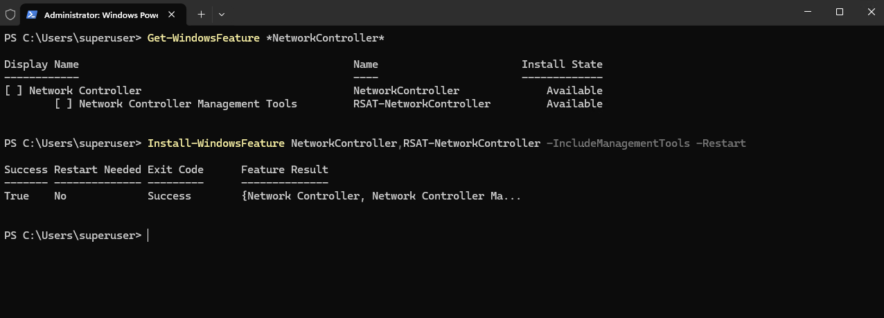
We first verify the available Network Controller features on both Hyper-V cluster nodes. On Matrix-HV-01 and Matrix-HV-02, the Network Controller role and its management tools are available but not yet installed.
Get-WindowsFeature *NetworkController*
We install the Network Controller role together with the corresponding management tools on each Hyper-V cluster node.
Microsoft explicitly requires a restart of every node after installing the Network Controller role, even if
Install-WindowsFeaturereportsRestart Needed: No
Install-WindowsFeature NetworkController,RSAT-NetworkController -IncludeManagementTools -Restart
We now first reboot Matrix-HV-01 and Matrix-HV-02 one at a time.
Installing SDN Express
For the PowerShell-based deployment, Microsoft provides SDN Express, which automates the deployment and configuration of the Software Defined Networking infrastructure.
We install the module on the first Hyper-V cluster node, Matrix-HV-01, from which we will perform the Network Controller deployment.
We run on Matrix-HV-01:
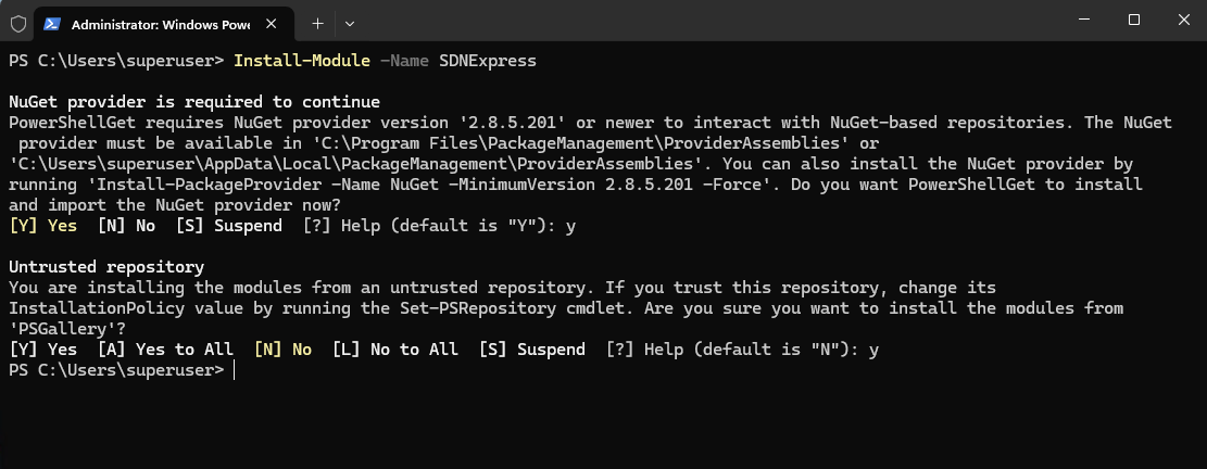
If PowerShell asks about installing NuGet or trusting PSGallery, accept it.
Install-Module -Name SDNExpress
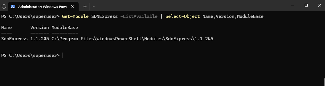
We verify the installed SDN Express module and confirm that version 1.1.245 is available.
This is newer than the minimum 1.1.231 version required by Microsoft for deploying the Windows Server 2025 Failover Clustering-based Network Controller.
Get-Module SDNExpress -ListAvailable | Select-Object Name,Version,ModuleBase
Verifying the Existing Hyper-V Cluster and Network Configuration
Before creating the SDN Express configuration, we first verify the existing Hyper-V cluster and network configuration that will be used for the Network Controller deployment.
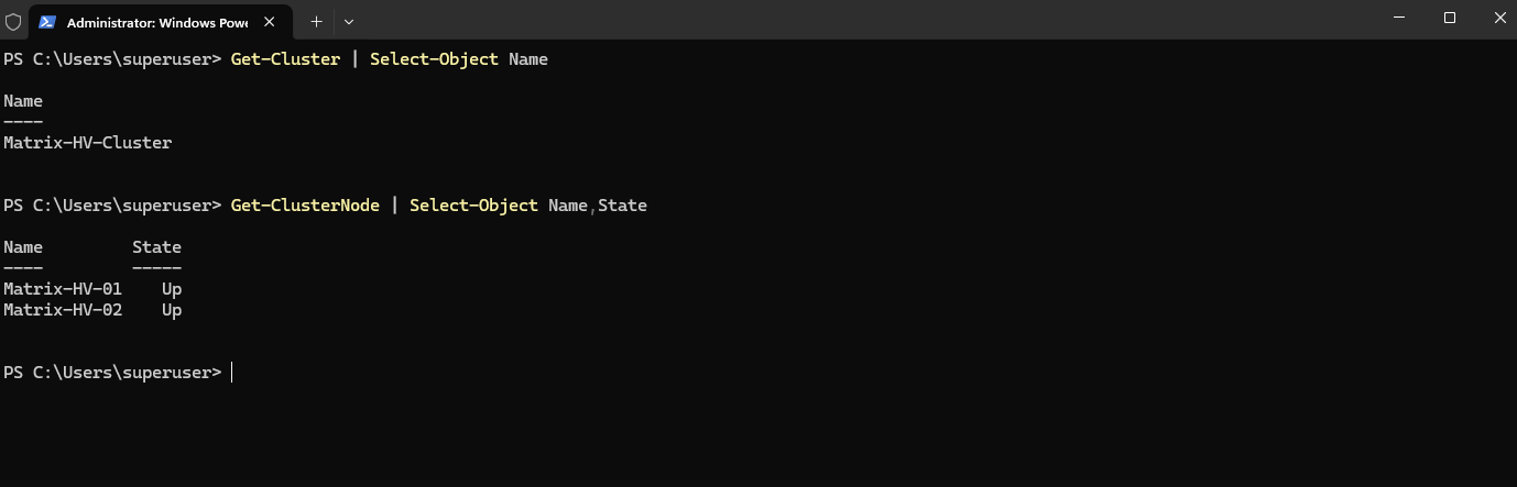
First, we confirm the cluster name and verify that both Hyper-V nodes are online:
Our
Matrix-HV-Clusterconsists of the two nodesMatrix-HV-01andMatrix-HV-02, both of which are currently online.
Get-Cluster | Select-Object Name
Get-ClusterNode | Select-Object Name,State
Next, we verify the existing Hyper-V virtual switches:
Both
vSwitch-MGMTandvSwitch-VMare external virtual switches configured with Switch Embedded Teaming (SET). The management switch provides connectivity for the Hyper-V hosts, whilevSwitch-VMis used for our VM workload networks.
Get-VMSwitch | Select-Object Name,SwitchType,EmbeddedTeamingEnabled

Finally, we verify the IPv4 configuration of the host:
On
Matrix-HV-01, the management interfacevEthernet (vSwitch-MGMT)uses10.0.0.50/24. This confirms the basic cluster, virtual switch, and management network configuration before we begin customizing the SDN Express deployment configuration.
Get-NetIPAddress -AddressFamily IPv4 | Where-Object {$_.IPAddress -notlike '169.254*' -and $_.IPAddress -ne '127.0.0.1'} | Select-Object InterfaceAlias,IPAddress,PrefixLength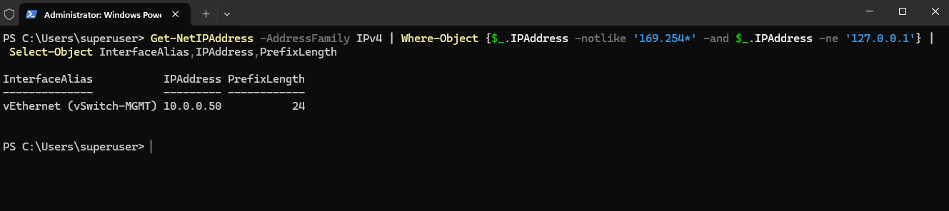
On Matrix-HV-02, Get-NetIPAddress additionally shows 10.0.0.55 on the management interface.
This address does not belong to the host itself; it is the Failover Cluster IP address of
Matrix-HV-Clusterand is currently hosted on this node. The actual management addresses of the Hyper-V hosts are10.0.0.50for Matrix-HV-01 and10.0.0.51for Matrix-HV-02.The reason
.55appeared inGet-NetIPAddresson Matrix-HV-02 is that the Cluster Group is currently owned by that node, so the cluster IP resource is online there. Cluster resource groups move between nodes during failover
Get-NetIPAddress -AddressFamily IPv4 | Where-Object {$_.IPAddress -notlike '169.254*' -and $_.IPAddress -ne '127.0.0.1'} | Select-Object InterfaceAlias,IPAddress,PrefixLength

# check cluster IP
Get-ClusterResource | Where-Object ResourceType -eq "IP Address" | Get-ClusterParameter | Where-Object Name -eq "Address"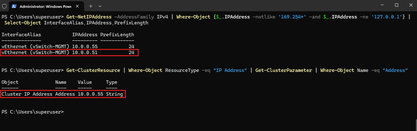
Preparing the SDN Express Configuration
The following SDN Express configuration and deployment steps are performed on Matrix-HV-01, which we use as the deployment node.
On this node, we previously installed the SDN Express PowerShell module, which provides Microsoft’s automated deployment framework for configuring the Software Defined Networking (SDN) infrastructure, including the Failover Clustering-based Network Controller.
The module does not need to be installed on Matrix-HV-02, as the deployment is initiated centrally from Matrix-HV-01.
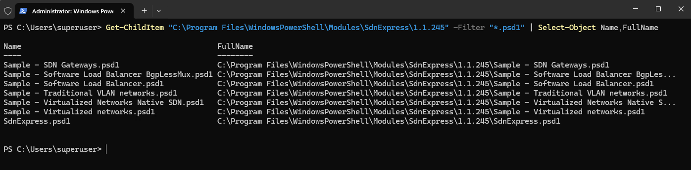
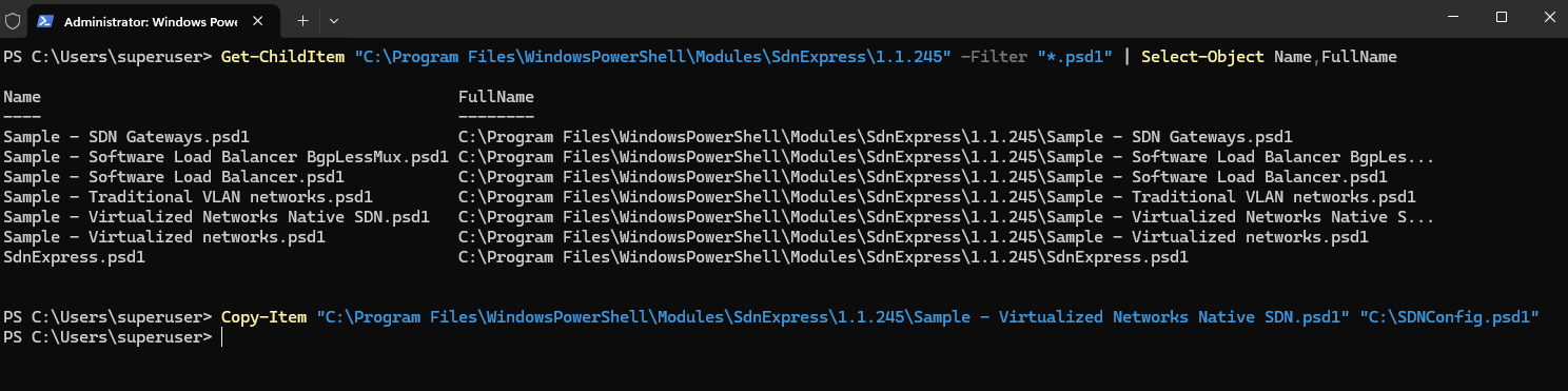
The installed SDN Express 1.1.245 module provides several predefined configuration templates. We first list the available templates:
SDN Express includes templates for several SDN scenarios, including SDN Gateways, Software Load Balancing, traditional VLAN networks, and virtualized networks.
For our Windows Server 2025 HNVv2 deployment, we use
Sample - Virtualized Networks Native SDN.psd1, which provides the configuration template for the new Failover Clustering-based Network Controller architecture.
Get-ChildItem "C:\Program Files\WindowsPowerShell\Modules\SdnExpress\1.1.245" -Filter "*.psd1" | Select-Object Name,FullName
We create a working copy of this template so that the original file remains unchanged:
Copy-Item "C:\Program Files\WindowsPowerShell\Modules\SdnExpress\1.1.245\Sample - Virtualized Networks Native SDN.psd1" "C:\SDNConfig.psd1"
Next, we review the default configuration before adapting it to our Hyper-V environment:
Get-Content "C:\SDNConfig.psd1"
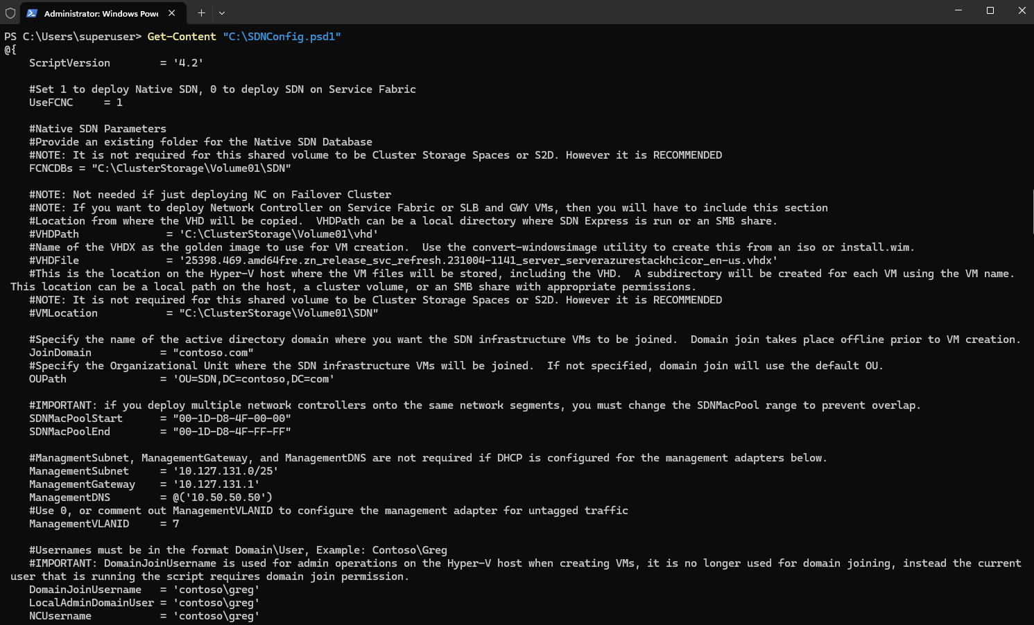
The configuration file contains all parameters supported by SDN Express, including settings for the Network Controller, management network, Hyper-V hosts, HNV Provider Address (PA) network, Software Load Balancer, gateways, and BGP.
Because we are initially deploying only the Failover Clustering-based Network Controller, not all parameters in the sample configuration are required at this stage.
The first setting is already correct:
This instructs SDN Express to deploy the native Failover Clustering Network Controller instead of the traditional Service Fabric-based Network Controller.
UseFCNC = 1

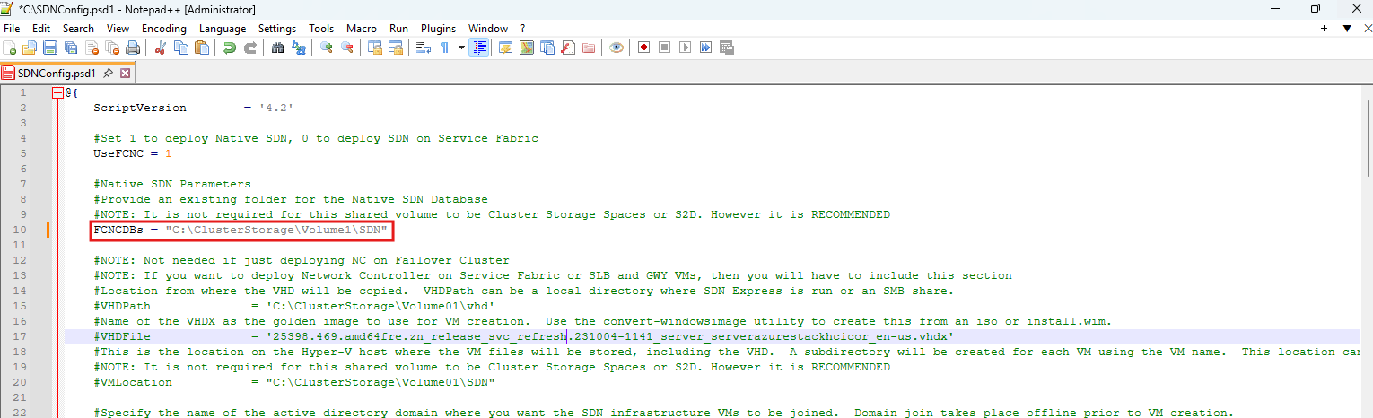
First thing we need to fix: FCNCDBs
The sample currently contains:
That’s just Microsoft’s sample path.
FCNCDBs = "C:\ClusterStorage\Volume01\SDN"
Since the Network Controller database needs to reside on storage accessible to the cluster nodes, let’s first check our actual CSV names on Matrix-HV-01:
The Failover Clustering-based Network Controller database must be stored in a location accessible to all cluster nodes.
In our lab, the existing Cluster Shared Volume is mounted at
C:\ClusterStorage\Volume1, so we use a dedicatedSDNfolder on this CSV for the Network Controller database.
Get-ClusterSharedVolume | Select-Object Name,@{N="Path";E={$_.SharedVolumeInfo.FriendlyVolumeName}}
We update the Failover Clustering-based Network Controller database (FCNCDBs) parameter to point to a dedicated SDN directory on our existing Cluster Shared Volume.
This location stores the database used by the Failover Clustering-based Network Controller and must therefore be accessible from all cluster nodes.
Next, we replace the sample Active Directory and management network settings in C:\SDNConfig.psd1 with the values used in our lab.
The Hyper-V management network is
10.0.0.0/24, using10.0.0.1as the default gateway and10.0.0.70as the DNS server. Because the management network is not VLAN-tagged on the Hyper-V hosts,ManagementVLANIDis set to0.
JoinDomain           = "matrixpost-lab.tech"
OUPath                  = 'OU=SDN,DC=matrixpost-lab,DC=tech'
ManagementSubnet     = '10.0.0.0/24'
ManagementGateway    = '10.0.0.1'
ManagementDNS        = @('10.0.0.70')
ManagementVLANID     = 0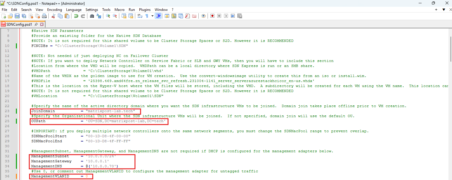
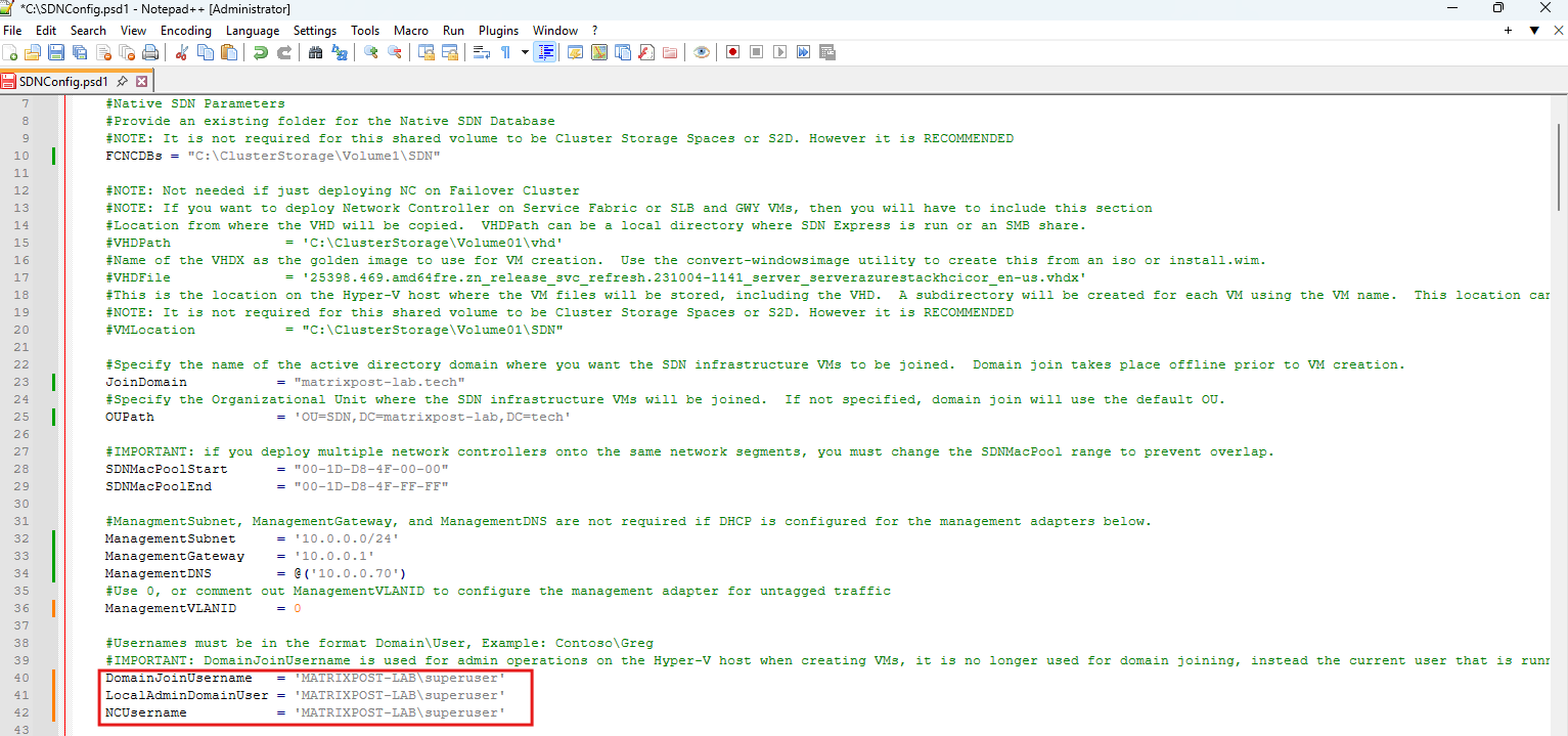
Next, we configure the domain accounts used by SDN Express during the deployment. In our lab, we use the existing MATRIXPOST-LAB\superuser administrative account for the Hyper-V host operations, local administrative access, and Network Controller operations.
And importantly, no password is stored in the PSD1. As the template notes, starting with SDN Express 4.0 the credentials are supplied separately when the deployment script is executed.
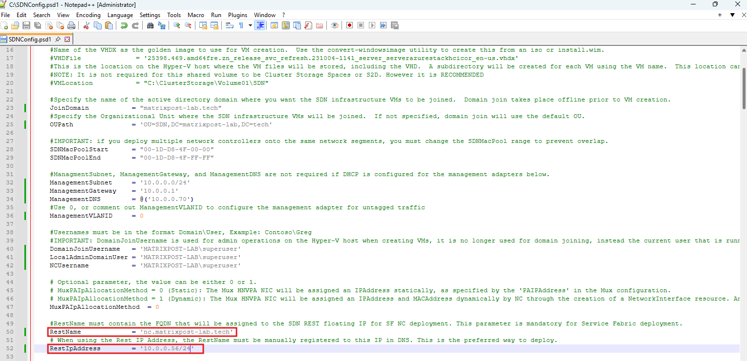
Next, we configure the Network Controller REST API endpoint. The REST endpoint provides the management interface through which SDN components and management tools communicate with the Network Controller.
With the Failover Clustering-based Network Controller, this endpoint uses a floating IP address, allowing it to remain available when the Network Controller service moves between cluster nodes.
The REST endpoint requires its own IP address on the management network and must not use one of the Hyper-V host addresses or the existing Failover Cluster IP address.
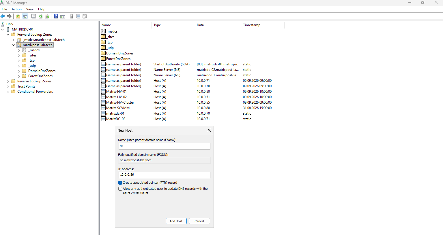
In our lab, we use nc.matrixpost-lab.tech as the DNS name and reserve 10.0.0.56 from the 10.0.0.0/24 management network for the REST endpoint.
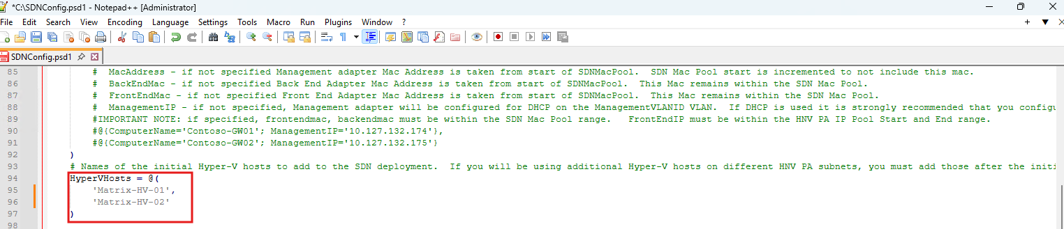
Next, we define the initial Hyper-V hosts that will participate in the SDN deployment. Because our lab consists of a two-node Hyper-V failover cluster, we add both Matrix-HV-01 and Matrix-HV-02 to the HyperVHosts array.
Configuring the Provider Address (PA) Network
Now we configure the Provider Address (PA) network, which is the physical underlay/transport network used by HNVv2.
While tenant VMs communicate using their Customer Addresses (CAs) inside virtual networks, the Hyper-V hosts encapsulate this traffic and transport it between hosts using Provider Addresses (PAs). Microsoft confirms that the PA is used in the outer Layer-3 header of the encapsulated traffic.
The relevant parameters in our template are:
PASubnet
PAVLANID
PAGateway
PAPoolStart
PAPoolEnd
For HNV, Microsoft recommends planning enough PA addresses because each physical Hyper-V host receives two PA IP addresses. Additional addresses are required if SLB MUX or Gateway VMs are deployed later.
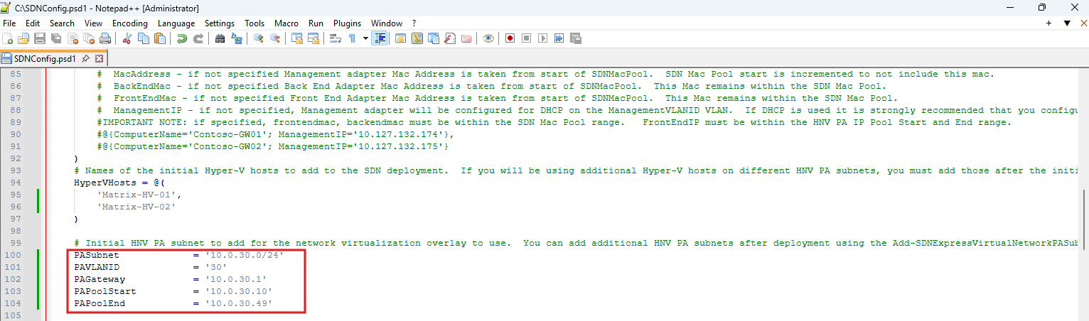
To keep the HNV transport network separated from both the management and existing workload networks, we create a dedicated VLAN 30 using the subnet 10.0.30.0/24.
SDN Express uses the configured PA address pool to dynamically assign Provider Addresses to the Hyper-V hosts.
These addresses form the underlay over which the encapsulated HNV tenant traffic is transported between the hosts.
For the HNV Provider Address network, we use the dedicated VLAN 30 with the subnet 10.0.30.0/24.
The provider network is routed through
10.0.30.1, while SDN Express assigns PA addresses dynamically from the configured range10.0.30.10to10.0.30.49.These addresses are used by the Hyper-V hosts as transport addresses for encapsulated HNV traffic.
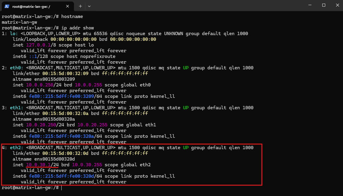
To provide a Layer-3 gateway for the new HNV Provider Address (PA) network, we add a third virtual network adapter to our existing Ubuntu router matrix-lan-gw.
The adapter is connected to vSwitch-VM, assigned to VLAN 30, and configured with 10.0.30.1/24. This address is subsequently used as the PAGateway in our SDN Express configuration.
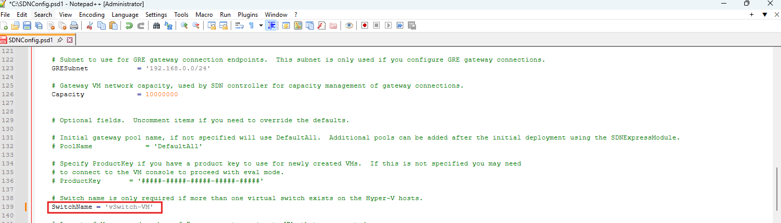
Because both Hyper-V hosts have multiple virtual switches, we explicitly specify vSwitch-VM as the switch used by the SDN deployment.
This switch represents our workload/data plane and is backed by the physical
VM-A/VM-Badapters connected to trunk ports, including VLAN 30 for the HNV Provider Address network.
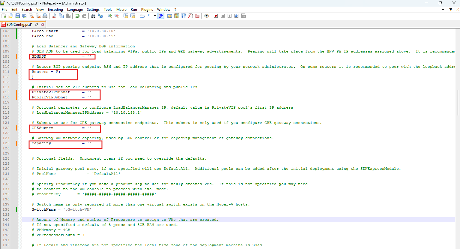
Since we are currently deploying only the Network Controller and HNV overlay, the settings for BGP, VIP networks, and GRE Gateway connectivity are not required.
We therefore clear the default sample values and will configure these parameters later when adding North-South connectivity and additional SDN services.
Provider Network and Physical Switch Connectivity
The Provider Address (PA) network belongs to the Hyper-V workload/data plane rather than the host management plane.
Therefore, the PA network should use the VM traffic vSwitch and its physical uplinks, while management traffic such as RDP, PowerShell, cluster management, and Active Directory communication remains on the dedicated management vSwitch.
In our lab, vSwitch-VM is backed by the physical adapters VM-A and VM-B, which are connected to 802.1Q trunk ports on the physical switches.
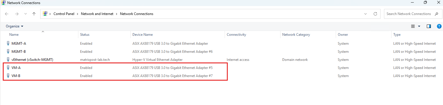
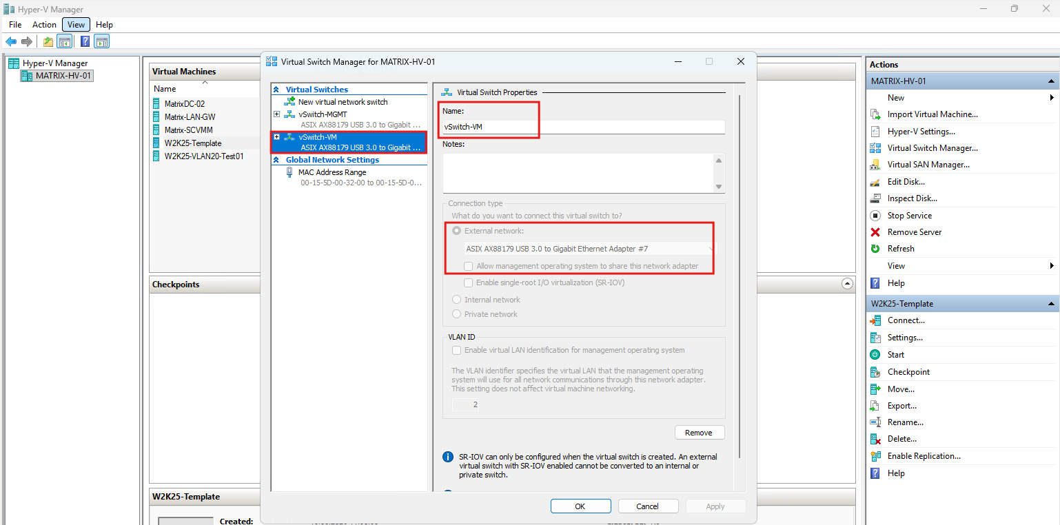
We therefore use this vSwitch for the HNV provider network and add VLAN 30 as the dedicated PA transport VLAN:
vSwitch-MGMT
  └─ MGMT-A / MGMT-B
       └─ Physical access ports → VLAN 10 (Management)

vSwitch-VM
  └─ VM-A / VM-B
       └─ Physical trunk ports
            ├─ VLAN 10
            ├─ VLAN 20
            └─ VLAN 30 → HNV PA network (10.0.30.0/24)
One nuance is important: the PA network itself does not require a trunk because HNV encapsulation does not create a separate physical VLAN for every tenant network.
From the physical network’s perspective, the encapsulated HNV traffic is transported over the single provider network, in our case VLAN 30.
The trunk is used because the same physical workload uplinks and vSwitch-VM also carry other VLAN-based VM networks and therefore need to transport multiple VLANs.
So the physical switches do not need to know about the later HNV tenant networks. If we create ten isolated tenant virtual networks later, we don’t create ten additional VLANs on the physical switches. Their encapsulated traffic can all traverse the same PA VLAN 30 between the Hyper-V hosts.
Configuring the Network Controller REST Endpoint
The Network Controller exposes its management API through a floating REST endpoint. In our lab, we assign the FQDN nc.matrixpost-lab.tech and the dedicated management IP address 10.0.0.56/24:
RestName      = 'nc.matrixpost-lab.tech'
RestIpAddress = '10.0.0.56/24'
Before continuing, we verify that 10.0.0.56 is not already in use and create the corresponding DNS records: an A record for nc.matrixpost-lab.tech → 10.0.0.56 and a PTR record for 10.0.0.56 → nc.matrixpost-lab.tech.
The SDN Express template explicitly notes that when a static REST IP address is used, the corresponding DNS record must be created manually.
Validating the SDN Express Configuration
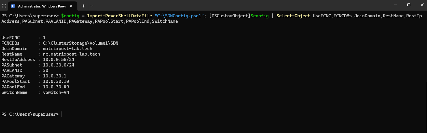
Before starting the actual deployment, we validate that the completed SDNConfig.psd1 file can be successfully parsed by PowerShell:
The configuration file imports successfully and the resulting values confirm our native Failover Clustering-based Network Controller deployment, REST endpoint, HNV Provider Address network, and
vSwitch-VMworkload switch configuration.With the SDN Express configuration validated, we can now proceed with the actual Network Controller deployment.
$config = Import-PowerShellDataFile "C:\SDNConfig.psd1"; [PSCustomObject]$config | Select-Object UseFCNC,FCNCDBs,JoinDomain,RestName,RestIpAddress,PASubnet,PAVLANID,PAGateway,PAPoolStart,PAPoolEnd,SwitchName
Deploying the Network Controller with SDN Express
Before deploying the Network Controller, ensure that the failover cluster computer object has permission to create the Network Controller virtual computer object in the configured SDN OU.
In my lab, I will delegate the required permission to the cluster computer object Matrix-HV-Clust$ on the entire OU=SDN, allowing the failover cluster to automatically create the required Network Controller computer object (VCO) in Active Directory.
dsacls "OU=SDN,DC=matrixpost-lab,DC=tech" /G 'MATRIXPOST-LAB\Matrix-HV-Clust$:CC;computer'
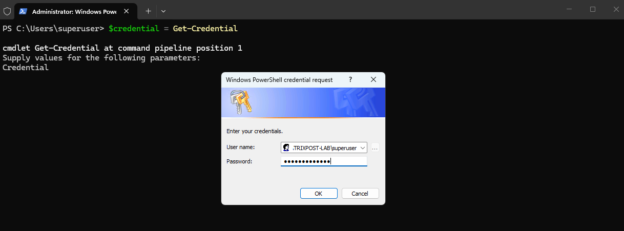
Next obtain the credentials used by SDN Express. In our lab, the same domain administrator account is used for all three roles:
$credential = Get-Credential
Then run SDN Express from the installed 1.1.245 module directory using our completed configuration file:
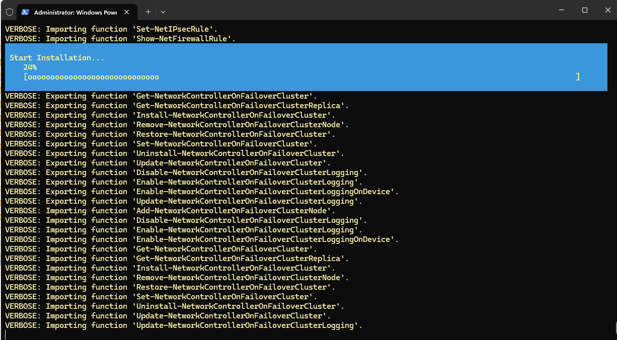
SDN Express now starts the installation of the Network Controller on the existing Windows Server 2025 failover cluster. During this process, the required Network Controller components and cluster services are configured on the Hyper-V hosts.
cd "C:\Program Files\WindowsPowerShell\Modules\SdnExpress\1.1.245"

.\SDNExpress.ps1 -ConfigurationDataFile "C:\SDNConfig.psd1" -DomainJoinCredential $credential -NCCredential $credential -LocalAdminCredential $credential -Verbose
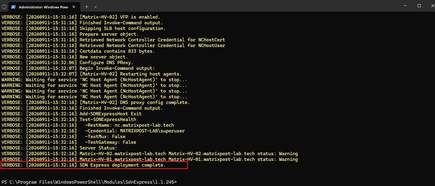
After the Network Controller deployment has completed, I verify the state of the deployed Network Controller cluster services.
All Network Controller microservices are Online and currently owned by
Matrix-HV-02, confirming that the native Windows Server 2025 Network Controller is successfully deployed and operational.
Get-ClusterGroup | Where-Object {$_.Name -match 'ApiService|ControllerService|FirewallService|FnmService|GatewayManager|ServiceInsertion|SlbManagerService|VSwitchService'} | Format-Table Name,State,OwnerNode -AutoSize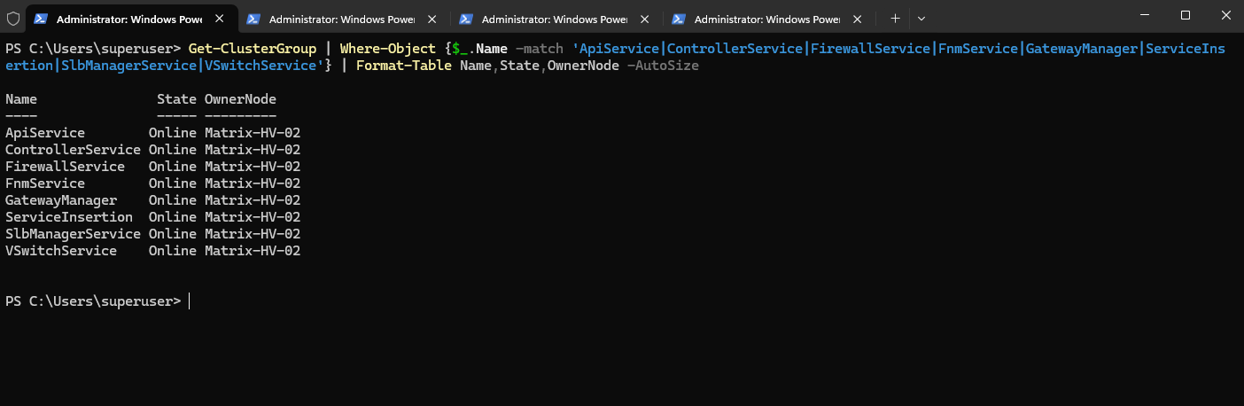
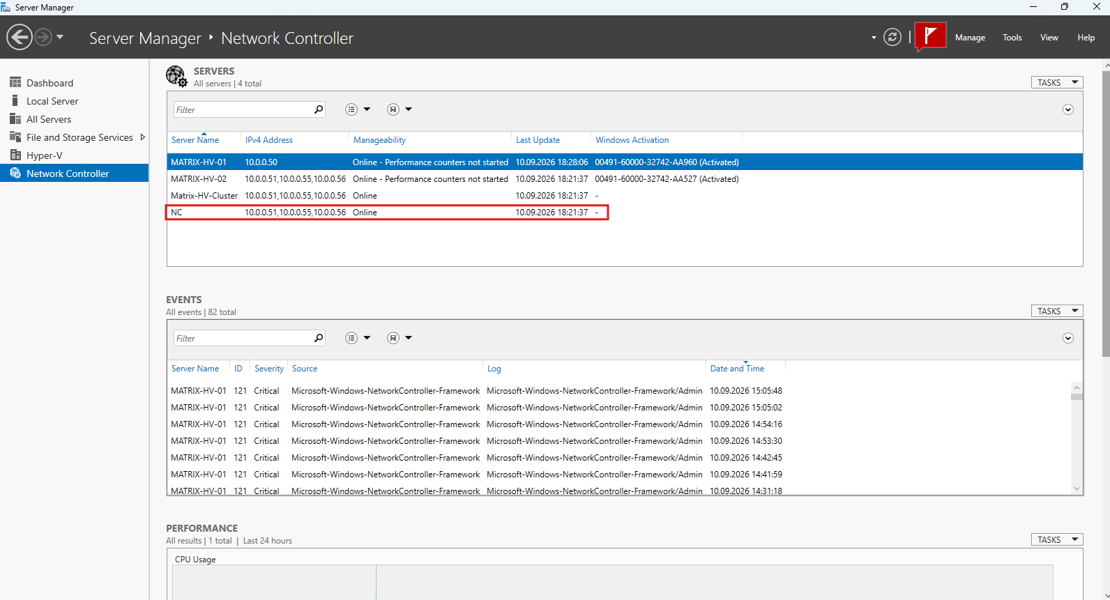
Server Manager now also shows the Network Controller and its associated cluster resources as Online, including the NC client access point with the floating REST IP address 10.0.0.56.
The critical Event ID
121entries shown below are historical events from the earlier failedApiServicestartup attempts, as described in the Troubleshooting section, and remain visible in the event history even though the Network Controller is now operational.
Configuring Hyper-V Network Virtualization
Configuring the HNV Provider Network
With the Network Controller successfully deployed, we can now start configuring Hyper-V Network Virtualization (HNV). The first component is the Provider Address (PA) network, which forms the physical underlay used to transport encapsulated HNV traffic between the Hyper-V hosts.
For this lab, we already defined the provider network while preparing SDNConfig.psd1:
Provider subnet:  10.0.30.0/24
VLAN ID:          30
Gateway:          10.0.30.1
PA pool:           10.0.30.10 - 10.0.30.49
Hyper-V switch:   vSwitch-VM
The physical switch ports connected to vSwitch-VM are configured as 802.1Q trunks carrying VLAN 30, while 10.0.30.1 on the matrix-lan-gw router provides the gateway for the provider network.
Unlike the Customer Addresses (CAs) assigned to tenant VMs, Provider Addresses (PAs) belong to the physical HNV transport network. Network Controller uses addresses from the configured PA pool to establish connectivity between the Hyper-V hosts and transport the encapsulated tenant traffic across the physical network.
With HNVv2, the forwarding and encapsulation policies are programmed into the Hyper-V virtual switch through VFP (Virtual Filtering Platform).
VFP is the programmable packet-processing layer integrated into the Hyper-V virtual switch. The Network Controller programs VFP with the forwarding and isolation policies required for HNV, including overlay encapsulation, address virtualization, ACLs, and other SDN functions.
At this point, the Provider Address network is defined, but no Provider Addresses have been assigned to the Hyper-V hosts yet. Network Controller allocates the required Provider Addresses dynamically when a running VM is connected to a virtualized network. We can verify this initial state with the following command:
Get-ProviderAddress

Creating the HNV Virtual Network (Isolated first Tenant Network)
With the Provider Address (PA) network prepared, we can now create the first HNV virtual network. The virtual network represents the isolated tenant network whose IP addresses are referred to as Customer Addresses (CAs).
These addresses are independent of the physical provider network and are transported between the Hyper-V hosts using the HNV overlay.
For this lab, I will use the following virtual network and Customer Address space:
Virtual network:    Tenant-CustomerA
CA address space:   192.168.100.0/24
Virtual subnet:     Tenant-CutomerA-Subnet
CA gateway:         192.168.100.1
The 192.168.100.0/24 Customer Address space exists only within the HNV virtualized network and does not require a corresponding physical VLAN on the network switches. From the perspective of the tenant VMs, they simply communicate using their normal IP addresses within this subnet.
On the physical network, however, HNV transports the tenant traffic between the Hyper-V hosts across the previously configured Provider Address network on VLAN 30 (10.0.30.0/24).
The Network Controller distributes the required forwarding and isolation policies to the Hyper-V hosts, while VFP applies these policies within vSwitch-VM.
This separation between Customer Addresses (CAs) and Provider Addresses (PAs) is one of the fundamental concepts of Hyper-V Network Virtualization: the tenant addressing is decoupled from the addressing and VLAN structure of the underlying physical network.
Next, we will create Tenant-CustomerA through the Network Controller and add its first virtual subnet.
First, we connect to the Network Controller REST endpoint and identify the HNV Provider Logical Network that was created during the SDN deployment.
Import-Module NetworkController
$uri = "https://nc.matrixpost-lab.tech"
$HNVProviderLogicalNetwork = Get-NetworkControllerLogicalNetwork -ConnectionUri $uri | Where-Object {$_.Properties.NetworkVirtualizationEnabled -eq $true}
Verify it with:
$HNVProviderLogicalNetwork | Select-Object ResourceId,@{N="NetworkVirtualizationEnabled";E={$_.Properties.NetworkVirtualizationEnabled}}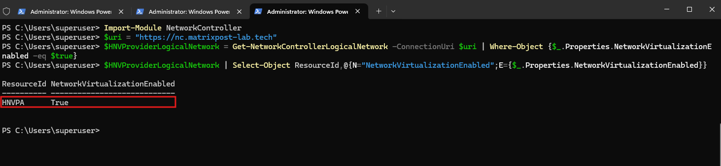
After the successful SDN Express deployment, the Network Controller now contains the HNV Provider Logical Network HNVPA.
The property NetworkVirtualizationEnabled = True confirms that this logical network is used as the provider network for Hyper-V Network Virtualization, while the single configured subnet represents the PA network defined in SDNConfig.psd1.
Now we can create our first HNV virtual network for Tenant-CustomerA and define its first virtual subnet using the Customer Address space 192.168.100.0/24.
$vsubnet = New-Object Microsoft.Windows.NetworkController.VirtualSubnet
$vsubnet.ResourceId = "Tenant-CustomerA-Subnet"
$vsubnet.Properties = New-Object Microsoft.Windows.NetworkController.VirtualSubnetProperties
$vsubnet.Properties.AddressPrefix = "192.168.100.0/24"

Then the virtual network properties:
$vnetproperties = New-Object Microsoft.Windows.NetworkController.VirtualNetworkProperties
$vnetproperties.AddressSpace = New-Object Microsoft.Windows.NetworkController.AddressSpace
$vnetproperties.AddressSpace.AddressPrefixes = @("192.168.100.0/24")
$vnetproperties.LogicalNetwork = $HNVProviderLogicalNetwork
$vnetproperties.Subnets = @($vsubnet)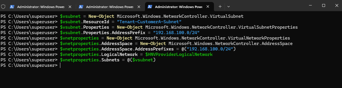
And finally:
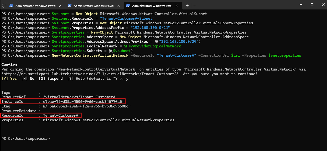
The Network Controller creates
Tenant-CustomerAas a new HNV virtual network and assigns it a uniqueInstanceId.Similar to the resource model used in Microsoft Azure, SDN resources are represented by properties such as
ResourceId,ResourceRef,InstanceId, andEtag.
New-NetworkControllerVirtualNetwork -ResourceId "Tenant-CustomerA" -ConnectionUri $uri -Properties $vnetproperties
Then verify with:
# if using a new PowerShell session
$uri = "https://nc.matrixpost-lab.tech"

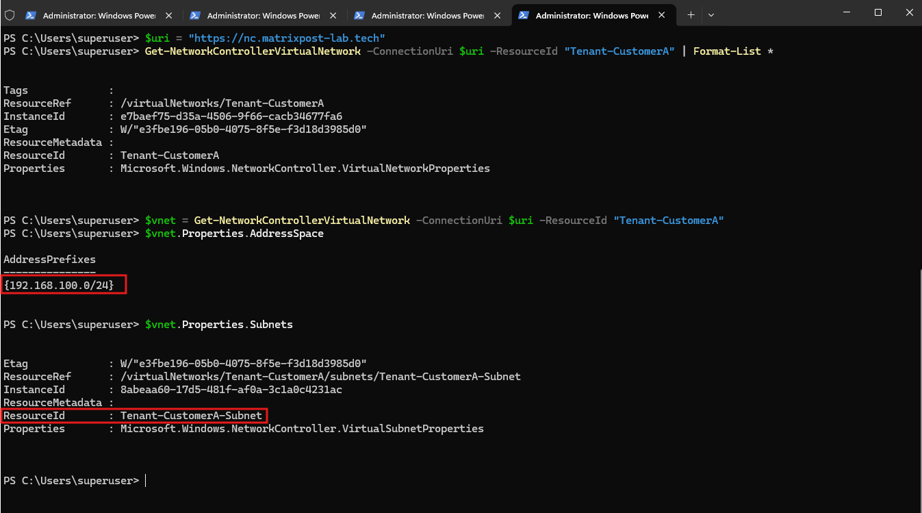
Get-NetworkControllerVirtualNetwork -ConnectionUri $uri -ResourceId "Tenant-CustomerA" | Format-List *
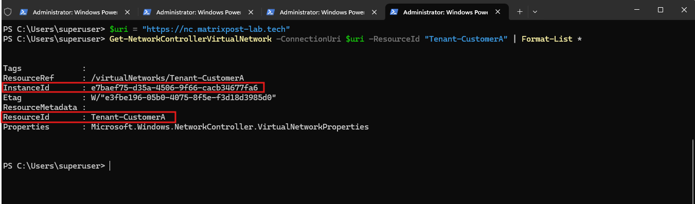
Because Format-List * only shows the top-level object, the useful next step is to expand its properties so we can see the CA address space and subnet:
The verification confirms that
Tenant-CustomerAhas been successfully created as an HNV virtual network.The returned object includes the Network Controller resource identifiers and the associated
VirtualNetworkProperties, which contain the Customer Address space and virtual subnet configuration.
$vnet = Get-NetworkControllerVirtualNetwork -ConnectionUri $uri -ResourceId "Tenant-CustomerA"
$vnet.Properties.AddressSpace
$vnet.Properties.Subnets
Creating a Tenant VM and Connecting It to the HNV Virtual Network
With the Tenant-CustomerA virtual network and its virtual subnet in place, we can now create the first tenant VM and connect it to the HNV virtual network.
The VM will use an IP address from the Customer Address space 192.168.100.0/24, while HNV transparently transports its traffic across the underlying Provider Address network.
For this lab, I will create a new Windows Server 2025 VM named Tenant-CustomerA-VM01 and connect its network adapter to vSwitch-VM.
The adapter will then be associated with the Tenant-CustomerA-Subnet through the Network Controller, rather than assigning a traditional VLAN ID to the VM.
Our existing vSwitch-VM remains the common data-plane vSwitch for both traditional VLAN-backed workloads and HNV tenant workloads.
SDN Express has now enabled VFP on that same switch, which is what allows Network Controller to program HNV policies into it.
Conceptually my lab is now:
                         vSwitch-VM
                             │
          ┌──────────────────┼──────────────────┐
          │                  │                  │
   Traditional VM      Tenant-CustomerA   Tenant-CustomerB
     VLAN 10/20          HNV overlay        HNV overlay
                           CA subnet          CA subnet
                       192.168.100/24     192.168.100/24
          │                  │                  │
          └──────────────────┴──────────────────┘
                             │
                    Physical NIC / trunk
                             │
                       VLAN 30 / HNVPA
                       10.0.30.0/24
The crucial distinction is that the tenant VM NIC itself isn’t simply configured with VLAN 30. VLAN 30 belongs to the PA underlay. VFP on vSwitch-VM applies the tenant’s HNV policy and the host encapsulates the tenant traffic for transport over that provider network.
That’s also why SDN Express earlier went through our existing VM adapters and added Null port profiles before enabling VFP: it was making sure our existing non-SDN workloads attached to vSwitch-VM continued to work.
Note: When SDN Express enables VFP on an existing Hyper-V virtual switch, it assigns a Null port profile to existing VM network adapters that are not managed by Network Controller.
This allows traditional non-SDN workloads to continue forwarding traffic through the VFP-enabled switch without applying HNV tenant policies to those ports.
To create the new tenant VM Tenant-CustomerA-VM01, I will use the Windows Server 2025 VM template created earlier in this series. The complete process of creating and deploying a new VM from this template is described in Part 4 below.
Creating the Tenant VM
Next, we deploy our first tenant workload, Tenant-CustomerA-VM01, which will later be connected to the HNV virtual network Tenant-CustomerA.
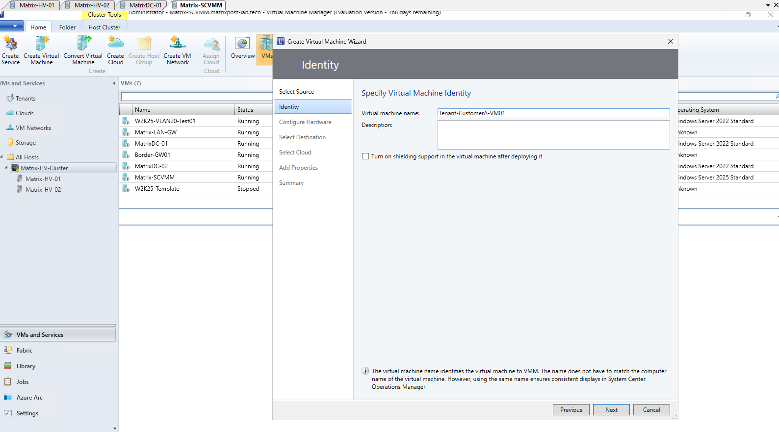
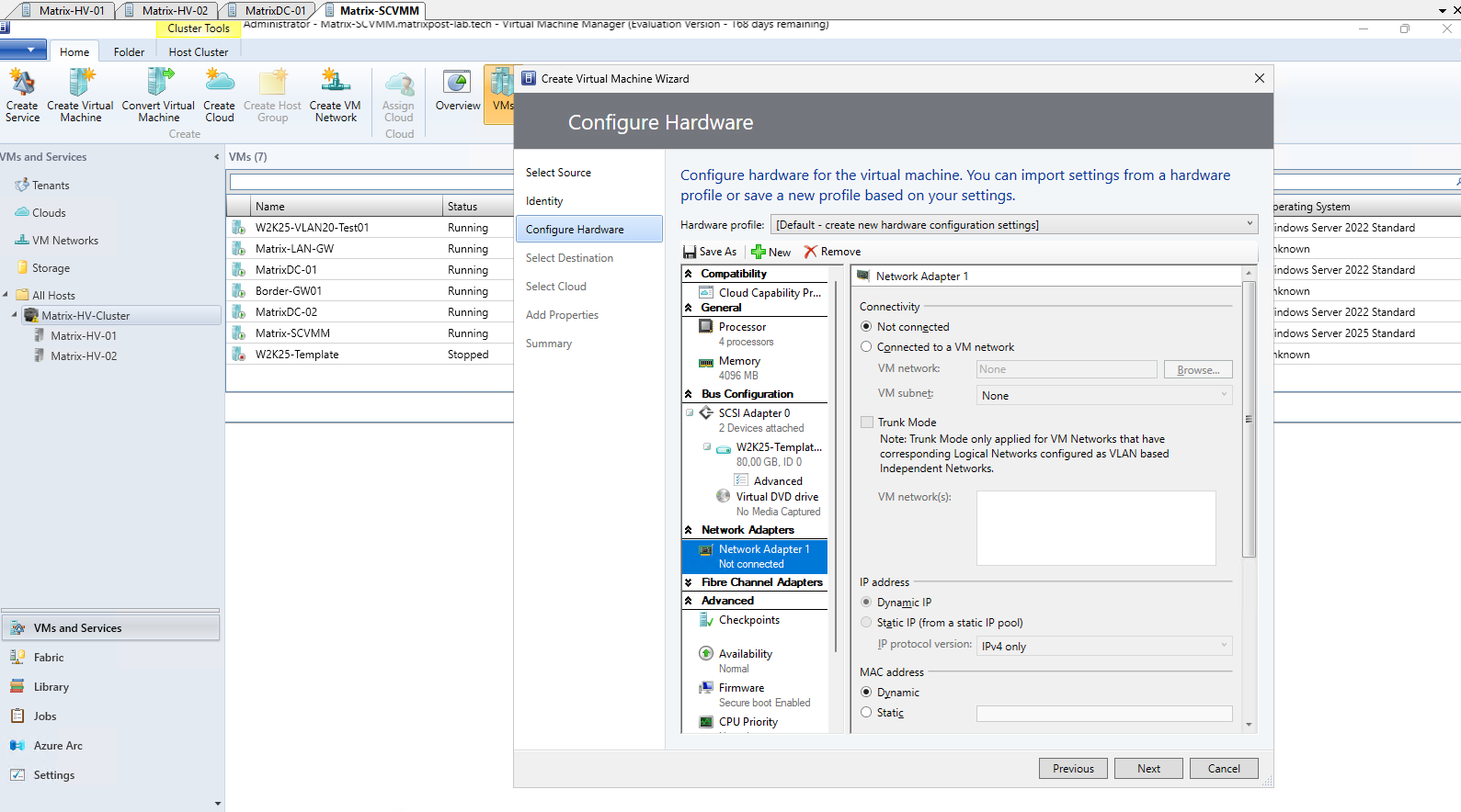
For the initial VM deployment, we leave the network adapter not connected and its MAC address assignment set to Dynamic. We also leave the VM powered off after deployment because the required SDN/HNV network configuration should be completed before the tenant VM is started.
For an SDN/HNV tenant VM, the network adapter must ultimately use a static MAC address that remains unchanged for the lifetime of the VM. Network Controller uses this address as part of the configuration of the tenant network interface.
Because the VM is created with its network adapter disconnected and is not started after deployment, Hyper-V does not yet allocate a dynamic MAC address. Instead of manually selecting an address, we will therefore use the MAC address pool managed by SCVMM to allocate an available MAC address and subsequently configure this address statically on the VM network adapter.
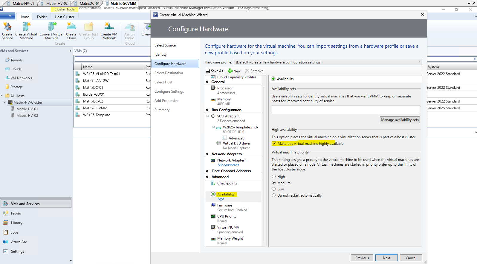
The tenant VM can also be configured as highly available. HNV is fully compatible with Hyper-V Failover Clustering, allowing the VM to fail over or Live Migrate between the cluster nodes while retaining its virtual network configuration and Customer Address.
Network Controller ensures that the required HNV policies are applied on the Hyper-V host currently running the VM.
Under Configure Settings, we can review and adjust the deployment-specific configuration of the new VM.
Here we select the Cluster Shared Volume (CSV) as the storage location and create/use a dedicated folder for the VM, while SCVMM also shows the virtual disk that will be deployed.
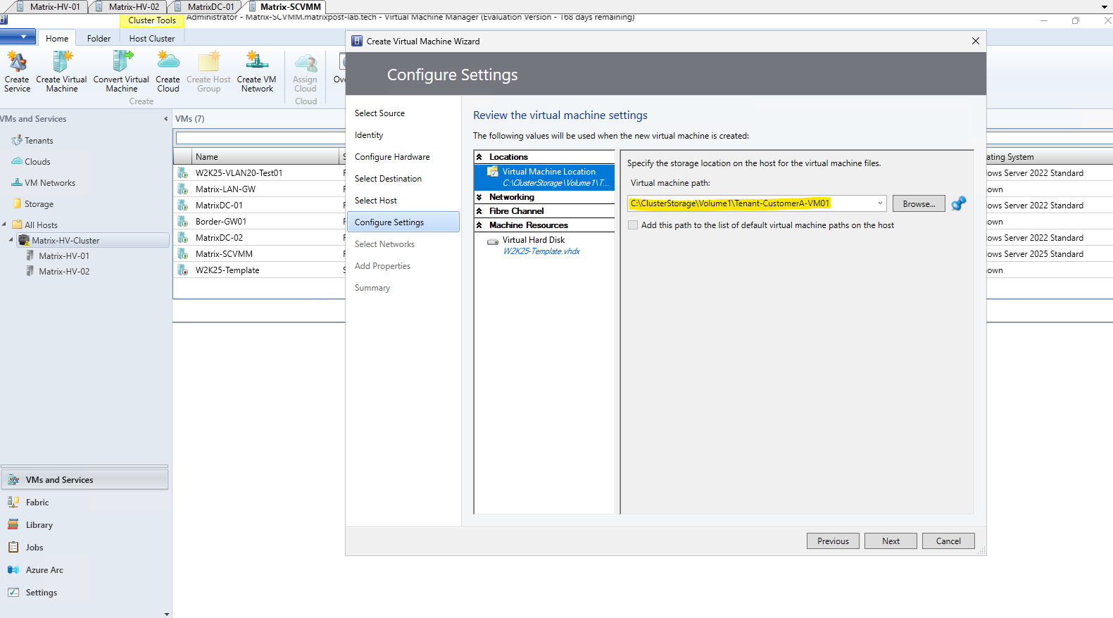
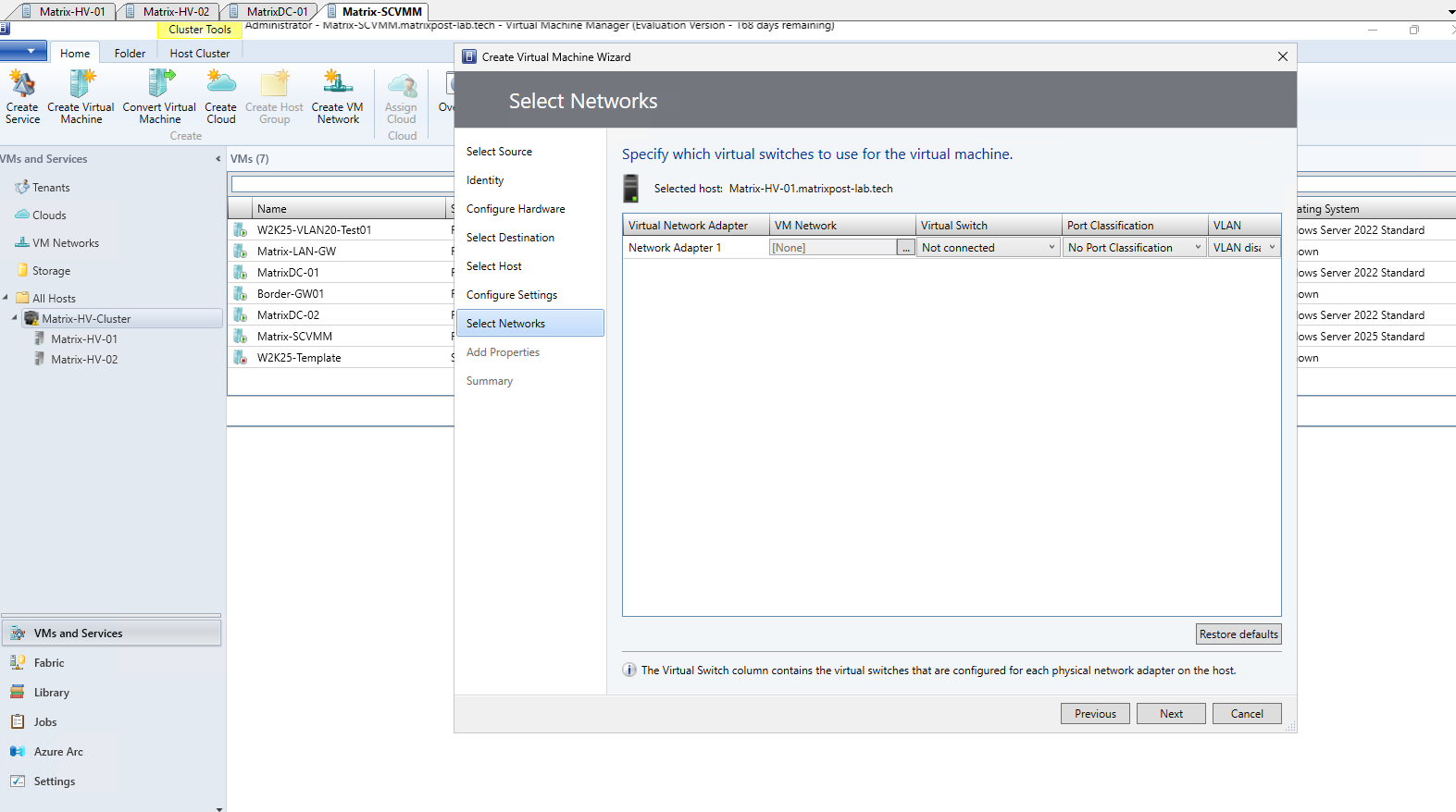
During the VM deployment, we leave the virtual network adapter to not connected as mentioned.
No VLAN is assigned to the tenant VM itself, as the tenant network is provided by the HNV overlay rather than a dedicated physical VLAN.
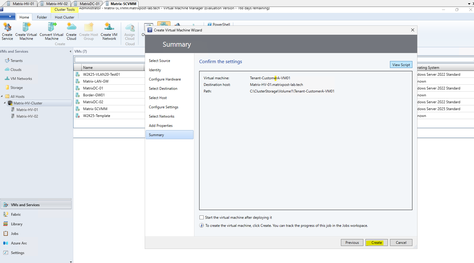
Finally, we leave Start the virtual machine after deploying it disabled.
Before starting the VM, we first need to configure its network adapter with a static MAC address, connect it to
vSwitch-VM, create the corresponding Network Controller network interface, and associate it withTenant-CustomerA-Subnet.
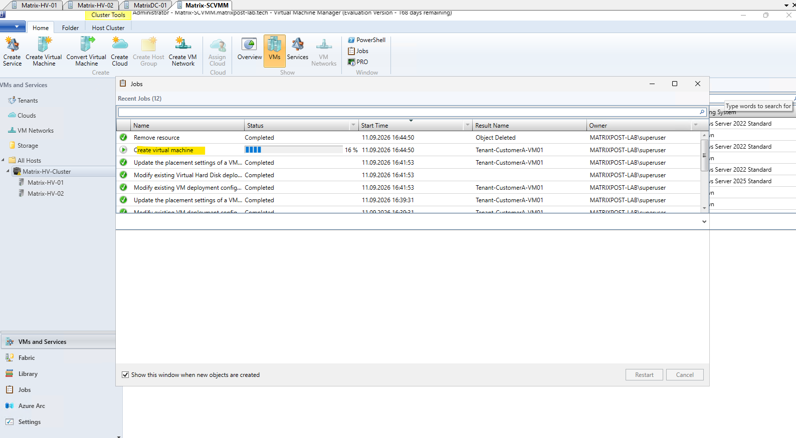
SCVMM now deploys the new Tenant-CustomerA-VM01 from the previously created Windows Server 2025 template.
The VM remains powered off and disconnected from the network, allowing us to configure its network adapter and Network Controller interface before its first startup.
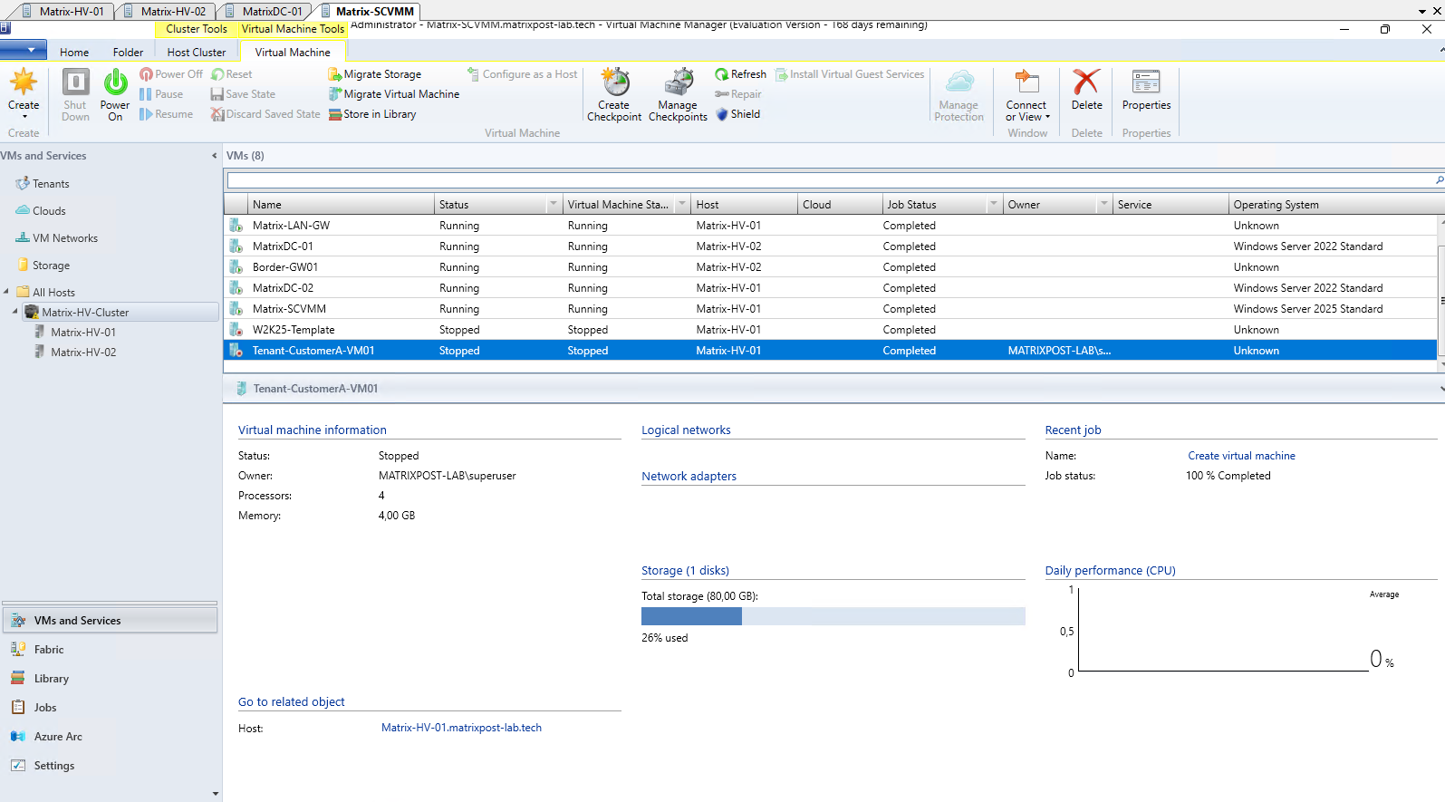
The deployment is complete, Tenant-CustomerA-VM01 is Stopped on Matrix-HV-01, exactly as intended.
Configuring the Static MAC Address
Before connecting Tenant-CustomerA-VM01 to the HNV virtual network, its network adapter must be configured with a static MAC address. For SDN/HNV tenant VMs, the MAC address must remain unchanged because Network Controller uses it when associating the VM network adapter with its SDN network interface and policies.
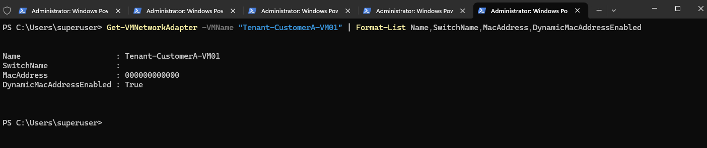
Because the VM was deployed with its network adapter to not connected and has not yet been started, Hyper-V has not allocated a dynamic MAC address. On Matrix-HV-01, we can verify the current state of the adapter:
The adapter currently shows no connected virtual switch and the placeholder MAC address
000000000000.
Get-VMNetworkAdapter -VMName "Tenant-CustomerA-VM01" | Format-List Name,SwitchName,MacAddress,DynamicMacAddressEnabled
Since the environment is managed by SCVMM, we do not manually select a MAC address. Instead, SCVMM maintains centralized MAC address pools from which it can allocate an available address.
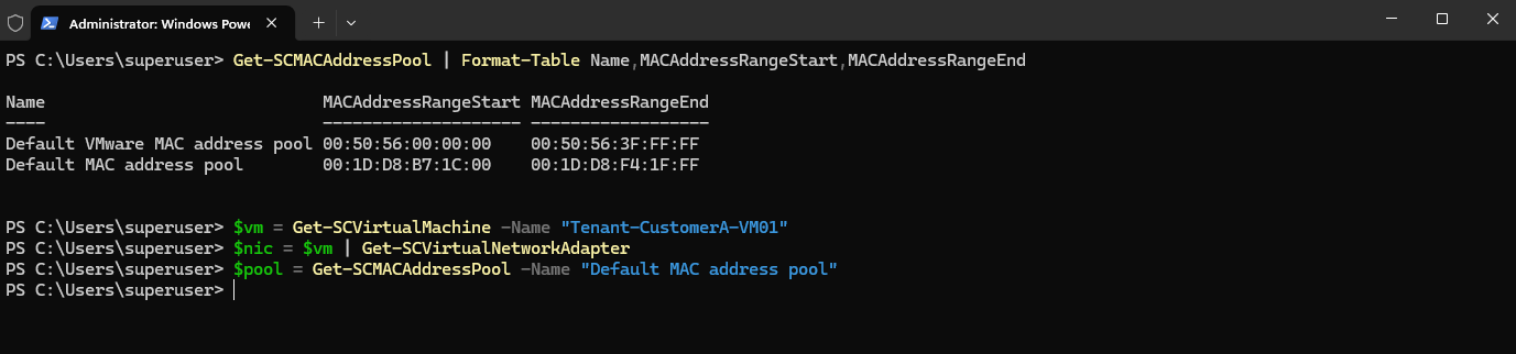
On the SCVMM server, we can display the configured pools with:
Get-SCMACAddressPool | Format-Table Name,MACAddressRangeStart,MACAddressRangeEnd

We first retrieve the tenant VM, its network adapter, and the corresponding SCVMM MAC address pool:
$vm = Get-SCVirtualMachine -Name "Tenant-CustomerA-VM01"
$nic = $vm | Get-SCVirtualNetworkAdapter
$pool = Get-SCMACAddressPool -Name "Default MAC address pool"
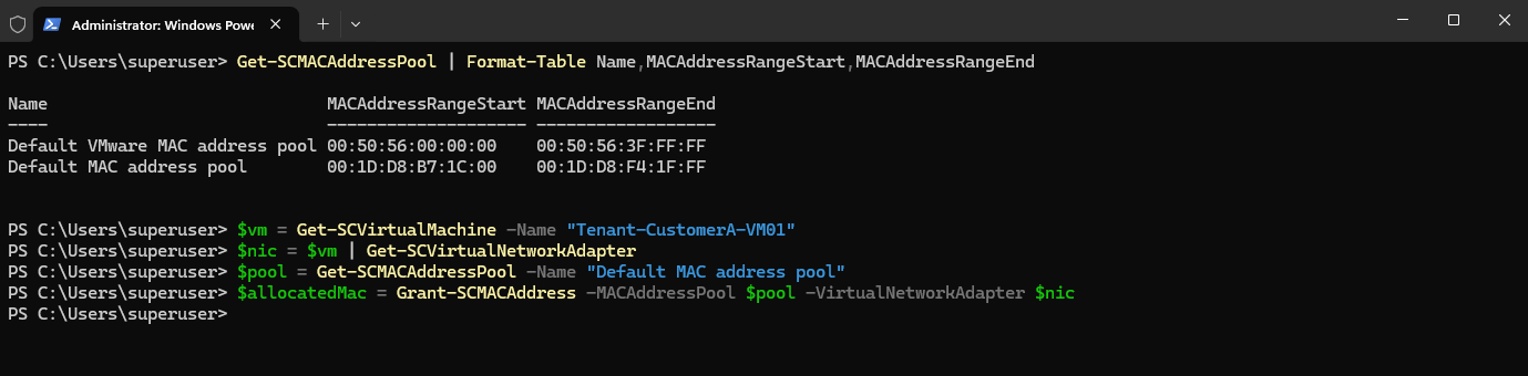
SCVMM can then allocate the next available MAC address from this pool and associate the allocation with the VM network adapter:
$allocatedMac = Grant-SCMACAddress -MACAddressPool $pool -VirtualNetworkAdapter $nic
The allocated address can be displayed with:
$allocatedMac | Format-List Address,State,VirtualNetworkAdapter,AllocatingAddressPool
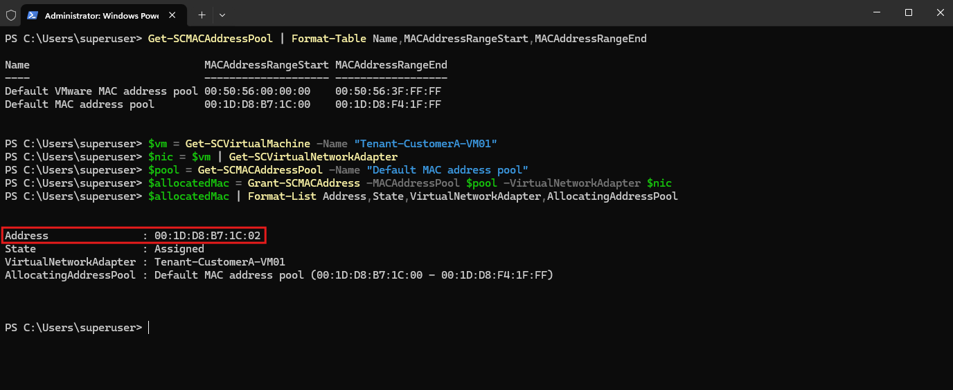
At this point, SCVMM has reserved the address, but the VM network adapter itself is still configured for dynamic MAC assignment. We therefore configure the address returned by SCVMM as the adapter’s permanent static MAC address:
Set-SCVirtualNetworkAdapter -VirtualNetworkAdapter $nic -MACAddressType Static -MACAddress $allocatedMac.Address
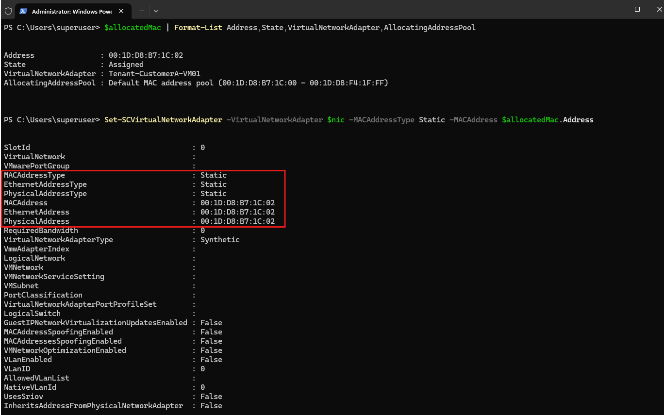
Finally, we verify the resulting configuration:
Get-SCVirtualMachine -Name "Tenant-CustomerA-VM01" | Get-SCVirtualNetworkAdapter | Format-List Name,MACAddress,MACAddressType

Connecting the Tenant VM to the Hyper-V Virtual Switch
With the static MAC address configured, we can now connect the network adapter of Tenant-CustomerA-VM01 to the existing vSwitch-VM on Matrix-HV-01.
The same Hyper-V virtual switch is used by the SDN infrastructure and HNV virtualized tenant networks. Once the virtual switch is managed by Windows Server SDN, the Microsoft Azure VFP (Virtual Filtering Platform) Extension applies the policies programmed by the Network Controller directly within
vSwitch-VM.VFP operates according to a default-deny model on the SDN-managed switch. VM network adapters that are not properly provisioned and associated with a corresponding Network Controller resource remain blocked at the VFP layer. Consequently, simply connecting a conventional VM or network appliance to
vSwitch-VMand assigning a VLAN is not sufficient; the port must also receive the appropriate Network Controller/VFP policy and resource binding before traffic can be forwarded.Configuring Hyper-V constructs like standard VLAN tagging, Trunk mode, or standard
VMNetworkAdapterIsolationis insufficient because Hyper-V passes the traffic to VFP, where VFP drops it for lacking an programmed Network Controller policy (port profile /InstanceId).
Instead, VFP (Virtual Filtering Platform) applies the policies programmed by Network Controller directly within vSwitch-VM.
Since the VM is currently hosted on Matrix-HV-01, the following commands are executed directly on Hyper-V node Matrix-HV-01.
We connect the tenant VM network adapter to the switch with:
Connect-VMNetworkAdapter -VMName "Tenant-CustomerA-VM01" -SwitchName "vSwitch-VM"

The resulting configuration can be verified with:
The output confirms that the adapter is connected to
vSwitch-VMand continues to use its previously configured static MAC address.
Get-VMNetworkAdapter -VMName "Tenant-CustomerA-VM01" | Format-List Name,SwitchName,MacAddress,DynamicMacAddressEnabled
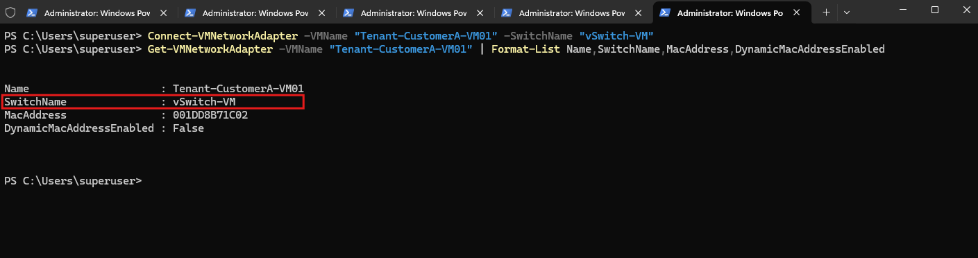
No VLAN ID is configured on the tenant VM network adapter. The Tenant-CustomerA network is an HNV overlay network, so its Customer Address space 192.168.100.0/24 does not correspond to a physical VLAN.
Note: This is conceptually similar to networking in hyperscale clouds such as Microsoft Azure. A tenant VM is connected to a software-defined virtual network rather than directly to a dedicated physical VLAN.
The SDN platform provides the logical network isolation and maps the tenant’s virtual network onto the shared physical underlay. With Microsoft SDN/HNV, Network Controller and VFP provide this abstraction, allowing multiple isolated tenant networks to share the same Hyper-V switches and physical network infrastructure.
The previously configured VLAN 30 is instead part of the underlying HNV Provider Address (PA) network 10.0.30.0/24.
VFP and Network Controller handle the mapping and transport of the tenant traffic across this provider network transparently.
At this point, the VM is connected to the correct Hyper-V virtual switch, but it is not yet associated with Tenant-CustomerA.
In the next step, we create the corresponding Network Controller network interface and associate it with Tenant-CustomerA-Subnet.
Creating the Network Controller Interface
Now that Tenant-CustomerA-VM01 is connected to vSwitch-VM, we need to create the corresponding Network Controller network interface. This object represents the VM network adapter within Microsoft SDN and associates it with the previously created Tenant-CustomerA-Subnet.
For this first tenant VM, we will use the following configuration:
| Setting | Value |
|---|---|
| VM | Tenant-CustomerA-VM01 |
| Static MAC | 00:1D:D8:B7:1C:02 |
| Customer Address | 192.168.100.10 |
| Virtual Network | Tenant-CustomerA |
| Virtual Subnet | Tenant-CustomerA-Subnet |
The following commands are executed on Matrix-HV-01, where the NetworkController PowerShell module is available.
First, connect to the Network Controller REST endpoint and retrieve the existing tenant virtual network:
Import-Module NetworkController
$uri = "https://nc.matrixpost-lab.tech"
$vnet = Get-NetworkControllerVirtualNetwork -ConnectionUri $uri -ResourceId "Tenant-CustomerA"

Next, create the properties for the Network Controller interface. The private MAC address must match the static MAC address that we previously configured on the Hyper-V VM network adapter.
$nicProperties = New-Object Microsoft.Windows.NetworkController.NetworkInterfaceProperties
$nicProperties.PrivateMacAddress = "001DD8B71C02"
$nicProperties.PrivateMacAllocationMethod = "Static"
$nicProperties.IsPrimary = $true

We then create an IP configuration for the VM’s Customer Address (CA) 192.168.100.10 and associate it with Tenant-CustomerA-Subnet:
$ipConfig = New-Object Microsoft.Windows.NetworkController.NetworkInterfaceIpConfiguration
$ipConfig.ResourceId = "Tenant-CustomerA-VM01-IPConfig"
$ipConfig.Properties = New-Object Microsoft.Windows.NetworkController.NetworkInterfaceIpConfigurationProperties
$ipConfig.Properties.PrivateIPAddress = "192.168.100.10"
$ipConfig.Properties.PrivateIPAllocationMethod = "Static"
$ipConfig.Properties.Subnet = New-Object Microsoft.Windows.NetworkController.Subnet
$ipConfig.Properties.Subnet.ResourceRef = $vnet.Properties.Subnets[0].ResourceRef
$nicProperties.IpConfigurations = @($ipConfig)
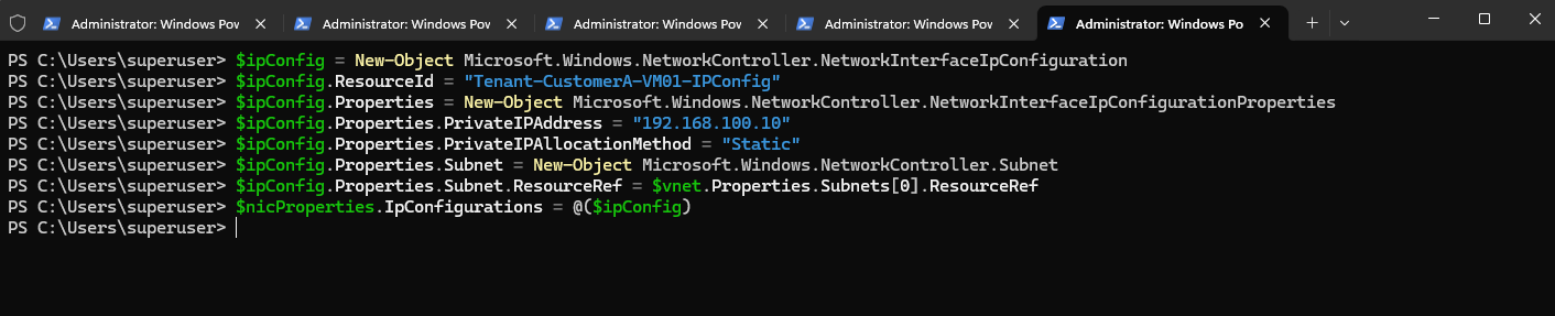
Finally, create the Network Controller interface:
Network Controller now has a logical representation of the VM network adapter containing its static MAC address, Customer Address, and HNV virtual subnet membership.
$ncNic = New-NetworkControllerNetworkInterface -ResourceId "Tenant-CustomerA-VM01-NIC" -ConnectionUri $uri -Properties $nicProperties

We can verify the created resource with:
The important value here will be the
InstanceId. In the next step, we bind this Network Controller interface to the actual Hyper-V network adapter ofTenant-CustomerA-VM01.That binding is what allows VFP to apply the
Tenant-CustomerAHNV policy to the VM port.
$ncNic | Format-List ResourceId,InstanceId,ResourceRef

Binding the Network Controller Interface to the VM Network Adapter
Creating the Network Controller interface alone does not yet associate it with the physical VM port on vSwitch-VM. The final step is therefore to bind the Network Controller interface InstanceId to the Hyper-V network adapter of Tenant-CustomerA-VM01.
This binding is implemented through a Hyper-V virtual switch extension port feature. The resulting port profile tells VFP which Network Controller interface, and therefore which HNV policies, belongs to this particular VM network adapter.
The following commands are executed on Matrix-HV-01, where Tenant-CustomerA-VM01 is currently located.
First, retrieve the Network Controller interface and the Hyper-V VM network adapter:
$uri = "https://nc.matrixpost-lab.tech"
$ncNic = Get-NetworkControllerNetworkInterface -ConnectionUri $uri -ResourceId "Tenant-CustomerA-VM01-NIC"
$vmNic = Get-VMNetworkAdapter -VMName "Tenant-CustomerA-VM01"
The Network Controller interface InstanceId can be verified with:
$ncNic.InstanceId
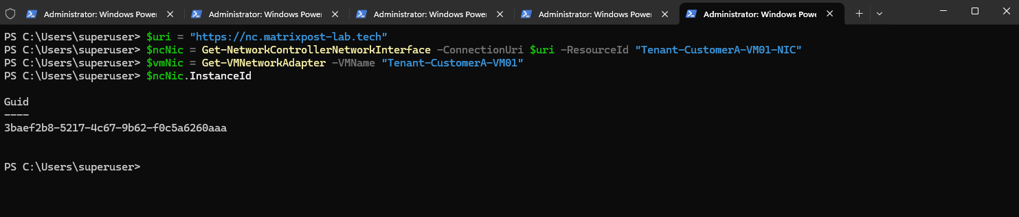
Next, we retrieve the Microsoft SDN VMSwitch extension port feature used to associate the Network Controller interface with the VM port:
$FeatureId = "9940cd46-8b06-43bb-b9d5-93d50381fd56"
$Feature = Get-VMSystemSwitchExtensionPortFeature -FeatureId $FeatureId
We then populate the port profile. Most importantly, ProfileId is set to the InstanceId of our Network Controller interface:
$Feature.SettingData.ProfileId = "{$($ncNic.InstanceId)}"
$Feature.SettingData.NetCfgInstanceId = "{56785678-a0e5-4a26-bc9b-c0cba27311a3}"
$Feature.SettingData.CdnLabelString = "Tenant-CustomerA-VM01"
$Feature.SettingData.CdnLabelId = 1111
$Feature.SettingData.ProfileName = "Tenant-CustomerA-VM01"
$Feature.SettingData.VendorId = "{1FA41B39-B444-4E43-B35A-E1F7985FD548}"
$Feature.SettingData.VendorName = "NetworkController"
$Feature.SettingData.ProfileData = 1
Finally, apply the Network Controller port profile to the VM network adapter:
Note: The GUID values used for
FeatureId,NetCfgInstanceId, andVendorIdare the fixed Microsoft identifiers used by the Network Controller port-profile configuration and should not be replaced with randomly generated GUIDs. The value that uniquely associates this VM with its Network Controller interface isProfileId, which contains theInstanceIdreturned when the interface was created.
Add-VMSwitchExtensionPortFeature -VMSwitchExtensionFeature $Feature -VMNetworkAdapter $vmNic
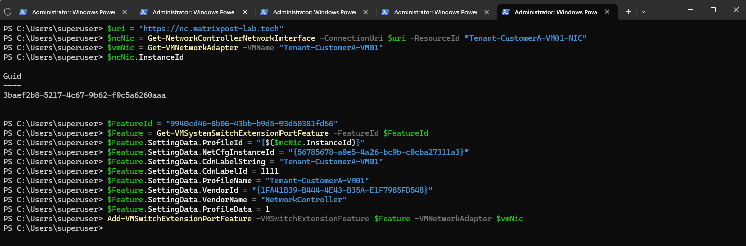
Verifying the Network Controller Port Profile
Before starting Tenant-CustomerA-VM01, we can verify that the Network Controller port profile has been successfully applied to its Hyper-V network adapter.
On Matrix-HV-01, retrieve the port feature assigned to the VM adapter:
The important value is
ProfileId. It should contain the sameInstanceIdthat Network Controller assigned toTenant-CustomerA-VM01-NIC.This confirms that the actual Hyper-V VM port on
vSwitch-VMis now associated with the corresponding Network Controller network interface.VFP can therefore identify the port as belonging to
Tenant-CustomerAand apply the HNV forwarding and isolation policies distributed by Network Controller.
$vmNic = Get-VMNetworkAdapter -VMName "Tenant-CustomerA-VM01"; $portFeature = Get-VMSwitchExtensionPortFeature -VMNetworkAdapter $vmNic -FeatureId "9940cd46-8b06-43bb-b9d5-93d50381fd56"; $portFeature.SettingData | Format-List ProfileId,ProfileName,VendorName,ProfileData
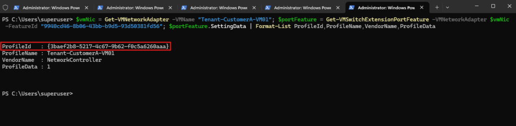
Starting the Tenant VM and Verifying Provider Address Allocation
With the Network Controller port profile successfully applied, Tenant-CustomerA-VM01 is now fully associated with its HNV virtual network and can be started.
On Matrix-HV-01, we start the tenant VM:
This is an important point in the HNV provisioning process. Until now, the Provider Address (PA) network was configured in Network Controller, but no Provider Addresses had been allocated to the Hyper-V host because no running workload was connected to an HNV virtual network.
Now that the first tenant VM is running on
Matrix-HV-01, Network Controller can allocate the required Provider Addresses from the PA pool configured earlier:
Start-VM -Name "Tenant-CustomerA-VM01"

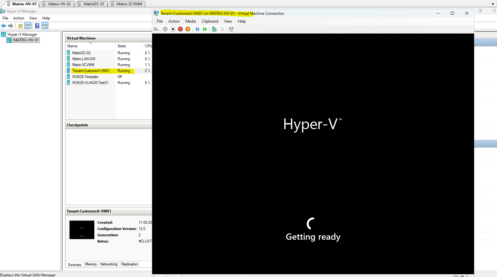
After starting
Tenant-CustomerA-VM01, Windows Server 2025 displays the Out-of-Box Experience (OOBE). This is expected because the VM was deployed from the Sysprep-generalized Windows Server 2025 template created earlier in this series. Sysprep removes the machine-specific configuration from the template, allowing each newly deployed VM to complete its own initial Windows setup when it is started for the first time.While the guest operating system is completing its initial setup, the VM itself is already running on
Matrix-HV-01with its network adapter associated with theTenant-CustomerAHNV virtual network. We can therefore now verify whether Network Controller has allocated the required Provider Addresses (PAs) to the Hyper-V host.
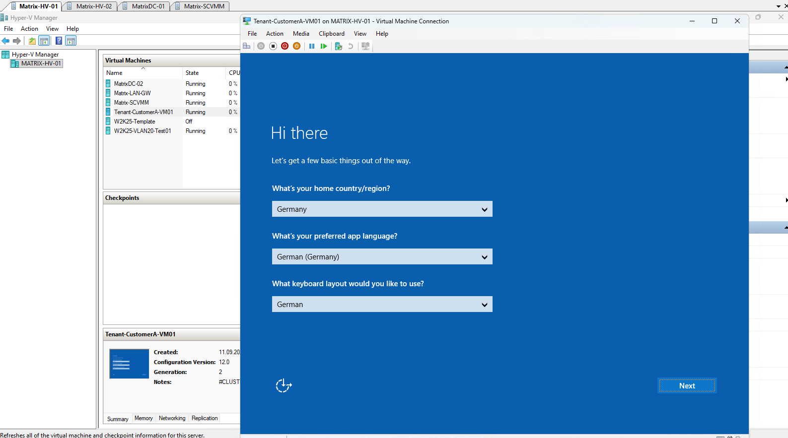
After completing the Windows Server 2025 initial setup, Hyper-V Manager already shows the network configuration associated with Tenant-CustomerA-VM01.
The VM is connected to vSwitch-VM, uses the previously configured static MAC address, and Hyper-V reports the Customer Address (CA) 192.168.100.10 that we defined in the Network Controller interface.
Notice that there is still no tenant VLAN involved. The VM simply sees and uses its Customer Address, while Network Controller and VFP provide the HNV mapping and transport across the underlying Provider Address network.
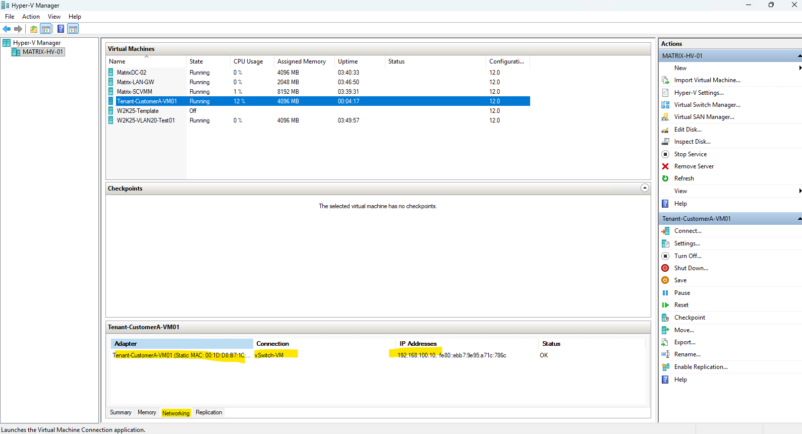
We can verify the Provider Address configuration directly on the Hyper-V host with:
Both addresses were allocated from the PA pool
10.0.30.10 - 10.0.30.49configured earlier for the HNV Provider Network. They use the expected VLAN 30,/24prefix, and default gateway10.0.30.1.
Get-ProviderAddress
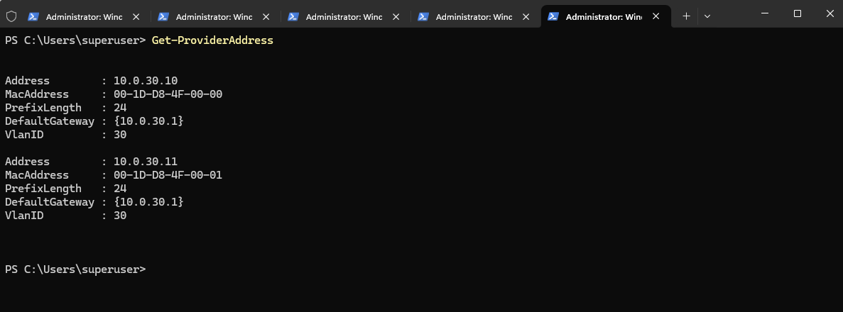
This clearly demonstrates the separation between the two address spaces:
- Customer Address (CA):
192.168.100.10— used byTenant-CustomerA-VM01 - Provider Addresses (PAs):
10.0.30.10and10.0.30.11— used by the Hyper-V host for HNV transport across the physical underlay
The tenant VM itself never needs to know about 10.0.30.0/24 or VLAN 30. From the guest’s perspective, it simply communicates using its own Customer Address, while Network Controller and VFP handle the mapping and encapsulated transport across the provider network.
Understanding Why Each Hyper-V Host Uses Two Provider Addresses
The output of Get-ProviderAddress shows an important detail that may not be immediately obvious. The two Provider Addresses 10.0.30.10 and 10.0.30.11 do not represent Matrix-HV-01 and Matrix-HV-02.
Both addresses have currently been allocated to Matrix-HV-01, because this is the first Hyper-V host running a VM connected to an HNV virtual network.
Matrix-HV-01
├── PA: 10.0.30.10
└── PA: 10.0.30.11

Matrix-HV-02
└── No Provider Addresses allocated yet
Network Controller allocates two Provider Addresses to a Hyper-V host when the first running guest VM on that host is connected to a tenant virtual network. These addresses are managed as part of the HNV data plane and allow the host to participate in the Provider Address network used to transport virtualized tenant traffic.
It is important not to confuse these addresses with the normal management IP address of the Hyper-V host. Matrix-HV-01 still uses 10.0.0.50 for its regular host management communication, while the newly allocated addresses belong to the dedicated HNV Provider Address network:
| Purpose | Address |
|---|---|
| Hyper-V host management | 10.0.0.50 |
| HNV Provider Address | 10.0.30.10 |
| HNV Provider Address | 10.0.30.11 |
| Tenant VM Customer Address | 192.168.100.10 |
The Provider Addresses are also associated with VLAN 30, the physical underlay VLAN configured earlier:
Tenant-CustomerA-VM01
CA: 192.168.100.10
        │
        ▼
      VFP / HNV
        │
Matrix-HV-01
PA: 10.0.30.10
PA: 10.0.30.11
        │
        ▼
VLAN 30 / 10.0.30.0/24
        │
        ▼
Physical network
At this stage, both Provider Addresses are local to Matrix-HV-01; they are not two ends of an HNV tunnel between the cluster nodes.
Matrix-HV-02 has not yet received Provider Addresses because it does not currently host a running HNV tenant VM.
Later, when we deploy another tenant VM on Matrix-HV-02 and connect it to the same Tenant-CustomerA virtual network, Network Controller should allocate Provider Addresses to that host as well.
We can then observe the complete cross-host HNV data path: the tenant VMs communicate using their Customer Addresses, while the Hyper-V hosts transport that traffic across the physical network using their Provider Addresses.
Note: Windows SDN allocates two Provider Addresses (PAs) to a Hyper-V host when it begins hosting HNV workloads. These should not simply be interpreted as a primary and secondary PA based on their allocation order. Both addresses are managed by Network Controller and used by the HNV data plane.
Troubleshooting
SDN Express Fails Exporting the Network Controller Node Certificate
During the first deployment attempt, SDN Express failed while preparing the node certificate for Matrix-HV-01. The deployment log showed that SDN Express discovered an existing certificate matching the FQDN of the Hyper-V host and attempted to reuse it:
[Matrix-HV-01] Using existing certificate with thumbprint A103277C85DD1D47F19F357C5025ABB1D44D18FE
[Matrix-HV-01] Setting permissions on node cert.
[Matrix-HV-01] Exporting node cert.
Exception calling "Export" with "2" argument(s): "Key not valid for use in specified state."
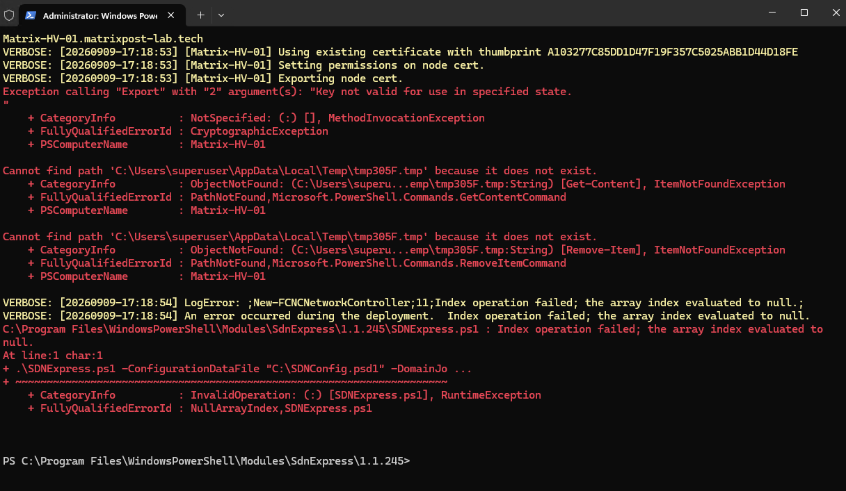
The subsequent Cannot find path and Index operation failed; the array index evaluated to null messages are secondary errors caused by the failed certificate export.
Checking the certificate revealed that it had previously been created by System Center Virtual Machine Manager (SCVMM):
$cert = Get-Item "Cert:\LocalMachine\My\A103277C85DD1D47F19F357C5025ABB1D44D18FE"; $cert | Select-Object Subject,FriendlyName,Thumbprint,HasPrivateKey,@{N="Exportable";E={$_.PrivateKey.CspKeyContainerInfo.Exportable}}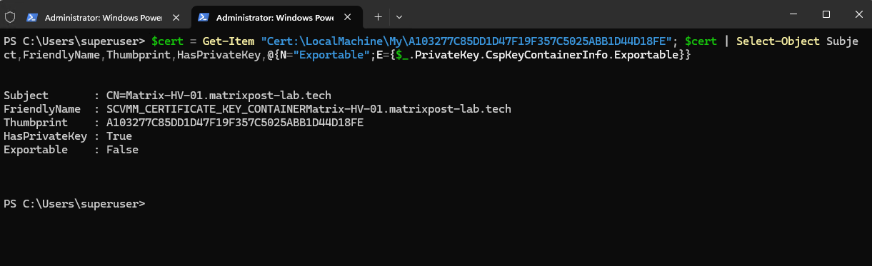
The certificate therefore contains a private key, but SCVMM created that private key as non-exportable.
Reviewing the SDN Express module revealed why this causes the deployment to fail. GetSdnCert searches the local computer certificate store for an existing certificate whose subject matches the node FQDN and which contains the required Server Authentication and Client Authentication EKUs. If multiple certificates match, the certificate with the latest expiration date is selected.
If no suitable certificate exists, SDN Express creates its own self-signed node certificate with an exportable private key:
New-SelfSignedCertificate -Type Custom -KeySpec KeyExchange -Subject "CN=$NodeFQDN" -KeyExportPolicy Exportable ...
However, because the existing SCVMM certificate satisfies the subject and EKU checks, SDN Express reuses it without checking whether its private key is exportable. It subsequently attempts to export the certificate as a PFX, causing the deployment to fail.
In our case, the conflict therefore results from deploying SDN Express on Hyper-V hosts that are already managed by SCVMM. The fix is to prevent SDN Express from selecting the non-exportable SCVMM host certificate and allow it to generate its own exportable node certificate instead.
Resolving the SCVMM Certificate Conflict
For the fix, we need to get the SCVMM certificate out of SDN Express’s search path temporarily without deleting its private key. The safest practical method is to move the certificate from LocalMachine\My to another local-machine store, run SDN Express, and move it back afterward.
The same condition was confirmed on both Hyper-V hosts: SCVMM had created host certificates matching the node FQDNs, but their private keys were not exportable.
To allow SDN Express to generate its own exportable node certificates, we temporarily move the SCVMM certificates out of the LocalMachine\My certificate store.
On Matrix-HV-01:
$s=New-Object System.Security.Cryptography.X509Certificates.X509Store("SDNTemp","LocalMachine");$s.Open("ReadWrite");$s.Close()
Move-Item "Cert:\LocalMachine\My\A103277C85DD1D47F19F357C5025ABB1D44D18FE" "Cert:\LocalMachine\SDNTemp"
On Matrix-HV-02:
Invoke-Command Matrix-HV-02 {$s=New-Object System.Security.Cryptography.X509Certificates.X509Store("SDNTemp","LocalMachine");$s.Open("ReadWrite");$s.Close();Move-Item "Cert:\LocalMachine\My\9EC440A37DC7026F567705F2A4DB3A1358C76A09" "Cert:\LocalMachine\SDNTemp"}After the SCVMM certificates are no longer present in LocalMachine\My, SDN Express cannot reuse them and instead creates new self-signed node certificates with an exportable private key, exactly as defined in the SDN Express module.
We can then rerun the SDN Express deployment. After the Network Controller deployment completes successfully, the original SCVMM certificates can be moved back into LocalMachine\My, allowing SCVMM and the Network Controller to continue using their respective certificates independently.
After the SDN Express deployment has completed, move the original SCVMM certificates back to LocalMachine\My.
Matrix-HV-01:
Move-Item "Cert:\LocalMachine\SDNTemp\A103277C85DD1D47F19F357C5025ABB1D44D18FE" "Cert:\LocalMachine\My"
Matrix-HV-02:
Move-Item "Cert:\LocalMachine\SDNTemp\9EC440A37DC7026F567705F2A4DB3A1358C76A09" "Cert:\LocalMachine\My"
Then verify both SCVMM certificates are back:
Get-ChildItem Cert:\LocalMachine\My | Where-Object {$_.FriendlyName -like "SCVMM_CERTIFICATE_KEY_CONTAINER*"} | Select-Object Subject,FriendlyName,ThumbprintNetwork Controller Network Name Fails Due to Missing Active Directory Permissions
During the initial SDN Express deployment using the SDNConfig.psd1 script, the clustered Network Controller network name NC failed to come online because the cluster computer object Matrix-HV-Clust$ did not have permission to create the required Virtual Computer Object (VCO) in the configured OU=SDN.
As a result, the Network Controller ApiService and other dependent services could not start successfully.
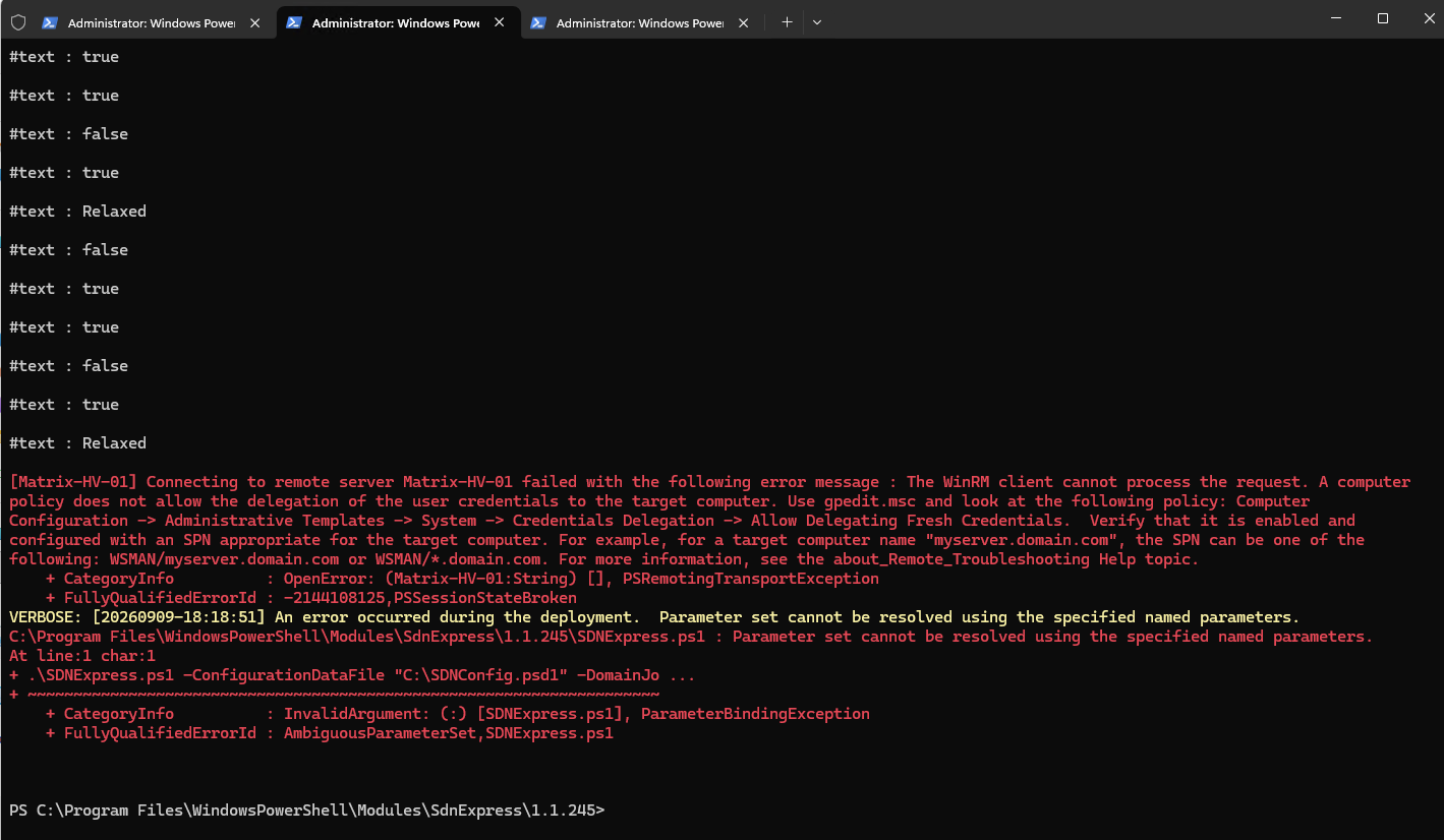
To recover the existing deployment, I first pre-staged the missing NC Virtual Computer Object (VCO) in the configured OU=SDN. I then granted the cluster computer object Matrix-HV-Clust$ Full Control over this object, allowing Failover Clustering to take ownership of it and configure the required Active Directory attributes, including the DNS hostname and Service Principal Names (SPNs).
Note that the account name containing the trailing
$must be enclosed in single quotes when runningdsaclsfrom PowerShell; otherwise, PowerShell interprets$as the start of a variable expression, resulting in theThe parameter is incorrecterror shown above.
New-ADComputer -Name "NC" -SamAccountName "NC$" -Path "OU=SDN,DC=matrixpost-lab,DC=tech" -Enabled $false
dsacls "CN=NC,OU=SDN,DC=matrixpost-lab,DC=tech" /G "MATRIXPOST-LAB\Matrix-HV-Clust$:GA"
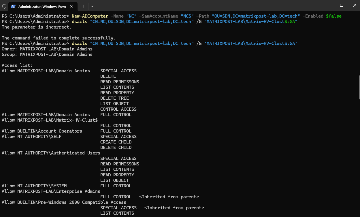
The assigned permissions can then be verified with dsacls by filtering the ACL of the pre-staged NC computer object for the cluster account. The output confirms that MATRIXPOST-LAB\Matrix-HV-Clust$ now has the required permissions on the NC VCO.
With the Active Directory object and permissions in place, I could bring the previously failed
NCNetwork Name cluster resource online:
dsacls "CN=NC,OU=SDN,DC=matrixpost-lab,DC=tech" | findstr /i "Matrix-HV-Clust

After pre-staging the VCO and assigning the required permissions, the previously failed NC Network Name resource could be started successfully. The additional cluster parameters confirm that Kerberos registration succeeded (StatusKerberos = 0), a domain controller was used to create/update the object, and an ObjectGUID was assigned to the corresponding Active Directory computer object.
The remaining
StatusDNS = 9005indicates that the dynamic DNS update was refused, which in this lab is related to the already existing manually created DNS record and does not prevent theNCresource from coming online.
Start-ClusterResource "NC"
Get-ClusterResource "NC" | Format-Table Name,State,OwnerGroup -AutoSize
 Get-ClusterResource "NC" | Get-ClusterParameter | Where-Object {$_.Name -in "StatusDNS","StatusKerberos","ObjectGUID","CreatingDC","LastDNSUpdateTime"}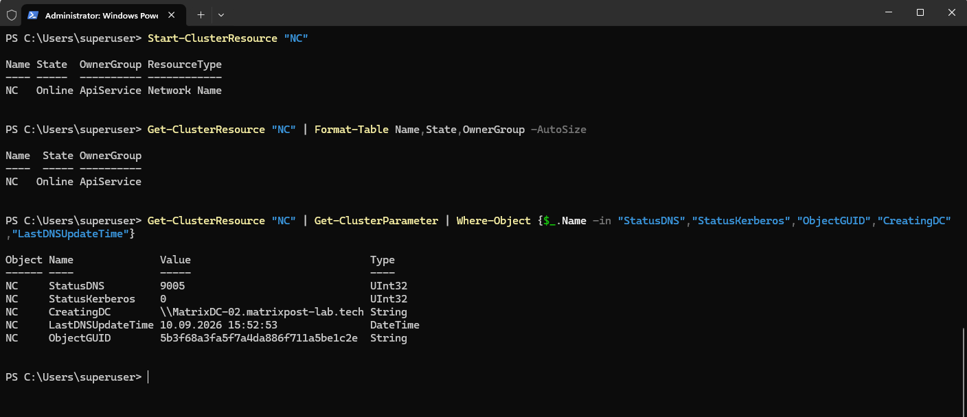
Finally, I verified the corresponding NC computer object in Active Directory. The object is now enabled, its DNS hostname is correctly set to NC.matrixpost-lab.tech, and the required Service Principal Names (SPNs) have been registered by Failover Clustering.
This confirms that the pre-staged VCO was successfully adopted and configured by the cluster and that the Active Directory/Kerberos side of the Network Controller access point is now healthy.
Get-ADComputer NC -Properties Enabled,DNSHostName,ServicePrincipalName | Select-Object Name,Enabled,DNSHostName,ServicePrincipalName

After the NC Network Name was online, I started the previously failed ApiService cluster resource. Both ApiService and the NC Network Name now reported an Online state.
The local
SDNApiServicestill appears as Stopped because the clustered service is currently owned by the other cluster node, Matrix-HV-02. With a clustered Generic Service, the Windows service runs only on the node currently owning the corresponding cluster role; therefore, this state onMatrix-HV-01is expected.
Start-ClusterResource "ApiService"
Get-ClusterResource "ApiService","NC" | Format-Table Name,State,OwnerGroup,ResourceType -AutoSize
Get-Service SDNApiService
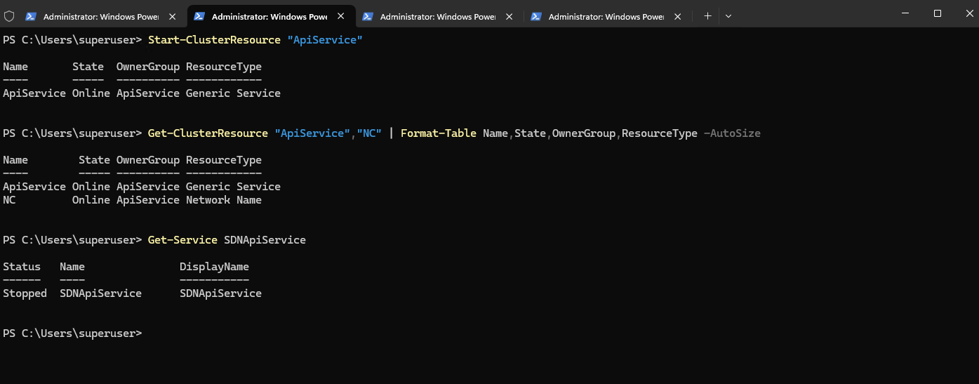
This confirms the expected failover cluster behavior. The ApiService role is currently owned by Matrix-HV-02, where SDNApiService is running, while the same service remains stopped on Matrix-HV-01.
This is expected because the Network Controller microservices are managed as clustered Generic Services and run only on the node currently owning their respective cluster role. The service therefore does not need to be running simultaneously on both Hyper-V hosts.
Get-ClusterGroup "ApiService" | Format-Table Name,State,OwnerNode -AutoSize; Get-ClusterResource "ApiService" | Format-Table Name,State,OwnerNode,OwnerGroup -AutoSize
Invoke-Command Matrix-HV-01,Matrix-HV-02 {Get-Service SDNApiService | Select-Object @{N='Node';E={$env:COMPUTERNAME}},Status,Name}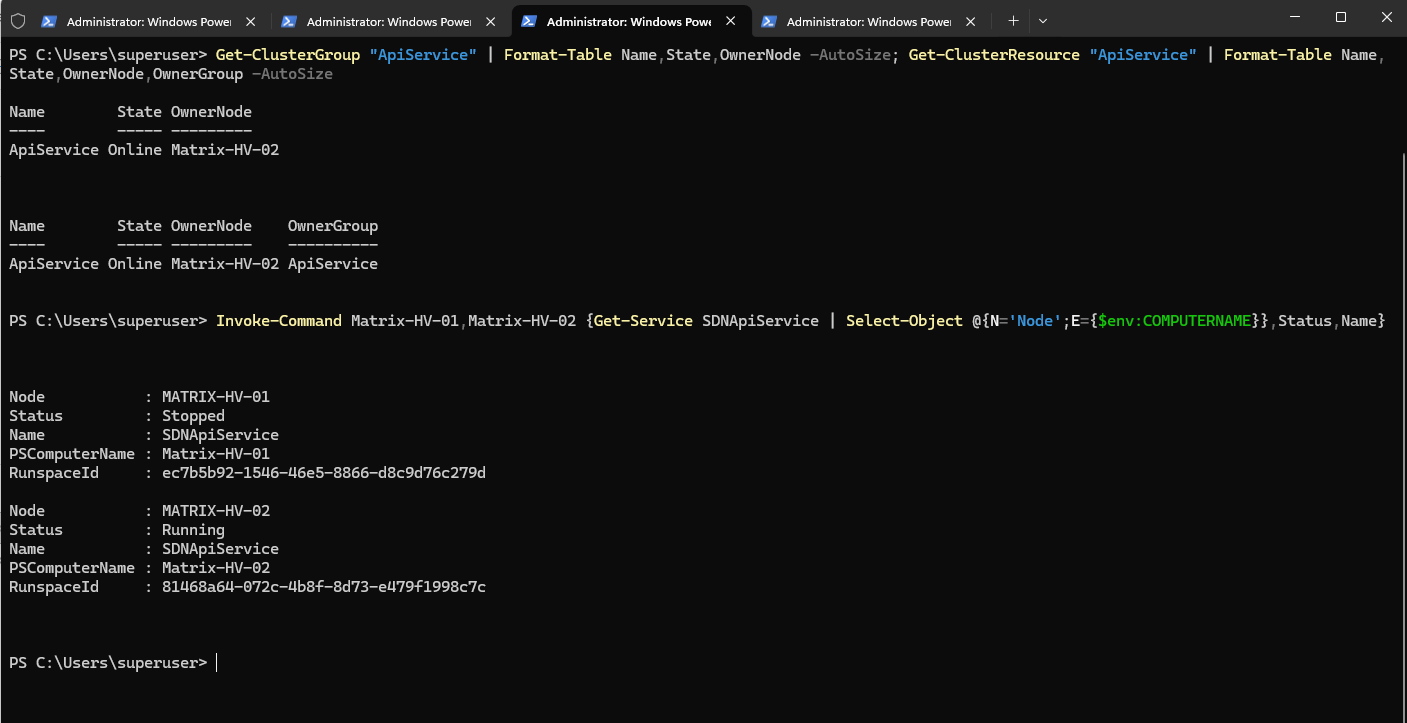
Finally, I verified the overall Network Controller failover cluster state. All Network Controller microservices, including ApiService, ControllerService, FirewallService, FnmService, GatewayManager, ServiceInsertion, SlbManagerService, and VSwitchService, are now Online.
The Network Controller REST endpoint resources, the 10.0.0.56 floating IP address and the
NCNetwork Name, are also online. This confirms that the native Windows Server 2025 Network Controller deployment is now fully operational after resolving the missing Active Directory permissions for the Network Controller VCO.
Get-ClusterGroup | Where-Object {$_.Name -match 'ApiService|ControllerService|FirewallService|FnmService|GatewayManager|ServiceInsertion|SlbManagerService|VSwitchService'} | Format-Table Name,State,OwnerNode -AutoSize
Get-ClusterResource | Where-Object {$_.OwnerGroup -match 'ApiService|ControllerService|FirewallService|FnmService|GatewayManager|ServiceInsertion|SlbManagerService|VSwitchService'} | Format-Table Name,State,OwnerGroup,OwnerNode,ResourceType -AutoSize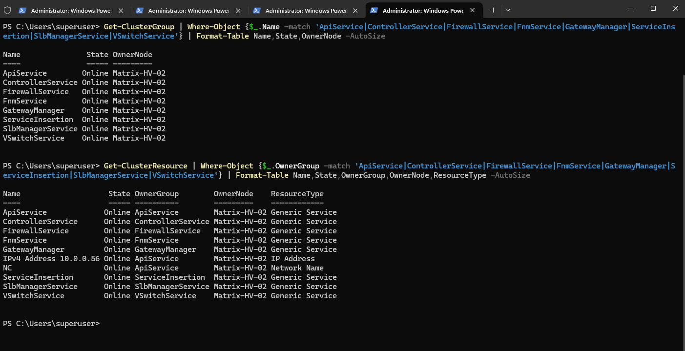
Server Manager may still show the Network Controller tile in red because it retains the previous critical events generated while the deployment was failing. This does not necessarily indicate a current failure; the cluster validation above confirms that all Network Controller resources and services are now Online.
The historical events can remain visible until the Server Manager event view refreshes or its configured event time window no longer includes them.
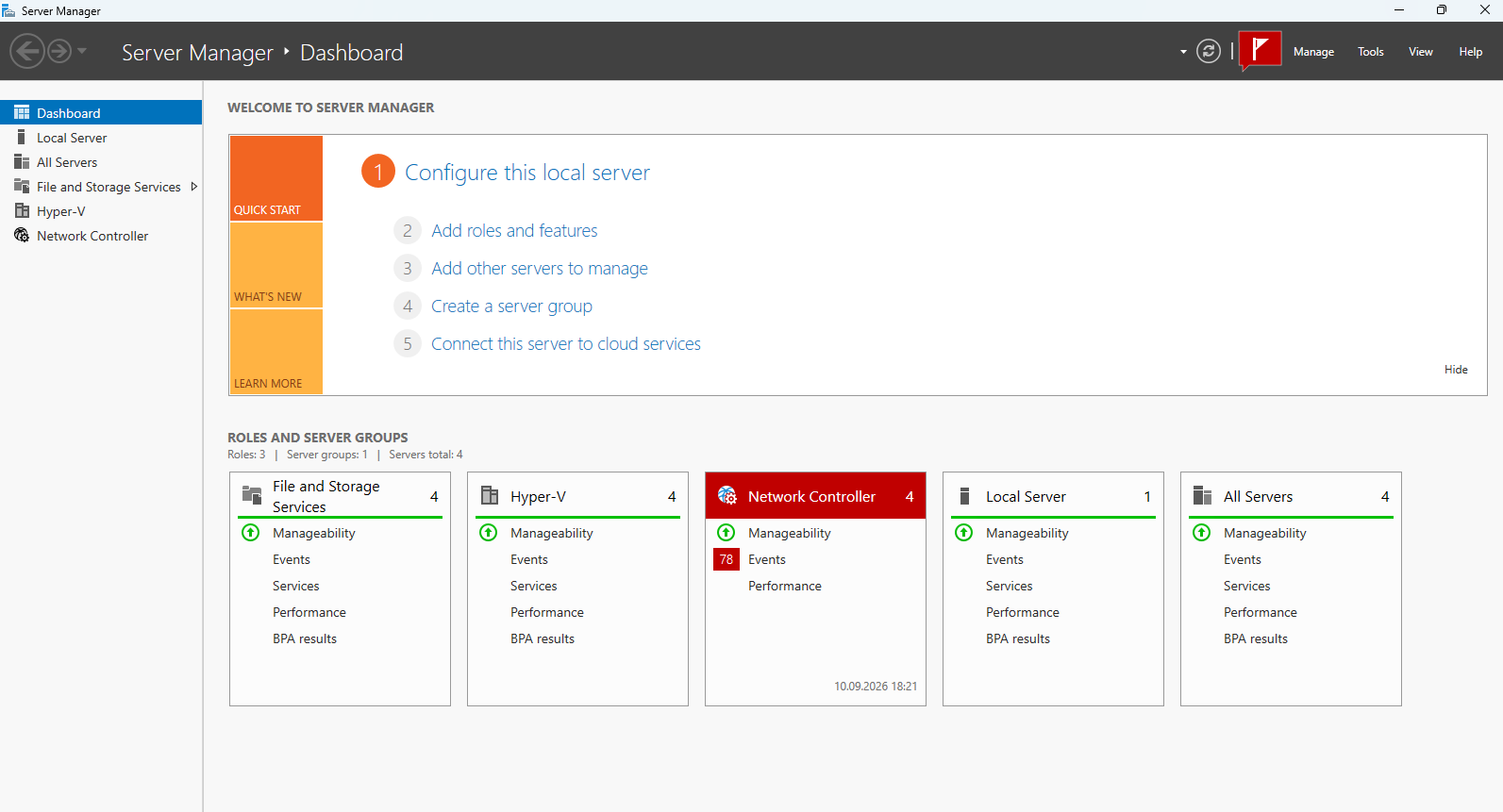
Links
Hyper-V Network Virtualization
https://learn.microsoft.com/en-us/windows-server/networking/sdn/technologies/hyper-v-network-virtualization/hyper-v-network-virtualizationHyper-V Network Virtualization Technical Details in Windows Server
https://learn.microsoft.com/en-us/windows-server/networking/sdn/technologies/hyper-v-network-virtualization/hyperv-network-virtualization-technical-details-windows-serverDeploy a Software Defined Network infrastructure
https://learn.microsoft.com/en-us/windows-server/networking/sdn/deploy/deploy-a-software-defined-network-infrastructureSet up Software Defined Network (SDN) components in the VMM fabric using PowerShell
https://learn.microsoft.com/en-us/system-center/vmm/sdn-powershellUpgrade System Center Virtual Machine Manager
https://learn.microsoft.com/en-us/system-center/vmm/upgrade-vmmDeploy Network Controller with Failover Clustering
https://learn.microsoft.com/en-us/windows-server/networking/sdn/deploy/deploy-network-controller-failover-clusteringTroubleshoot the Windows Server software defined networking stack
https://learn.microsoft.com/en-us/troubleshoot/windows-server/software-defined-networking/troubleshoot-windows-server-software-defined-networking-stackWill SCVMM 2025 be able to use and manage SDN Network Controller deployed as native Failover Cluster resource
https://learn.microsoft.com/en-us/answers/questions/5948099/will-scvmm-2025-be-able-to-use-and-manage-sdn-netwAzure Virtual Filtering Platform (VFP)
https://www.microsoft.com/en-us/research/project/azure-virtual-filtering-platform/