Software Defined Networking (SDN) with VMware NSX – Part 1: Deploying and Configuring NSX Manager
VMware NSX is VMware’s software-defined networking (SDN) platform, providing network virtualization and security independently of the underlying physical network. It extends traditional vSphere networking with capabilities such as overlay networks, distributed routing, micro-segmentation, and centralized network management.
In this first part, we will deploy the VMware NSX Manager appliance, perform the initial configuration, and integrate NSX with our existing VMware vCenter Server. This establishes the management plane and prepares our vSphere environment for the NSX networking components and overlay networks that we will configure in the following parts.
In Part 2, we will configure NSX Tier-1 and Tier-0 gateways, upstream routing, and Internet connectivity using a Linux router with VRFs and Source NAT.
In Part 3, we will build isolated multi-tenant overlay networks with overlapping IP address spaces, including identical host IP addresses, and demonstrate simultaneous Internet (WAN) access for both tenants.
In Part 4 we take a look at troubleshooting commands that help us understand and diagnose our NSX environment. We will also compare connection tracking and stateful firewall behavior across platforms such as Linux, Juniper, Cisco, Check Point, Fortinet and pfSense.
This series complements my existing Microsoft Hyper-V Network Virtualization (HNV) series, where we explored Microsoft’s approach to software-defined networking using the Network Controller, Virtual Filtering Platform (VFP), VXLAN overlays, and virtualized tenant networks.
With VMware NSX, we will now look at how similar SDN concepts are implemented in a VMware vSphere environment.
Download the VMware NSX Manager Appliance
VMware NSX Manager is delivered as a preconfigured virtual appliance in OVA format. It provides the centralized management and control plane for the NSX environment and will later be integrated with our existing vCenter Server and ESXi hosts.
The current VMware NSX installation media can be downloaded from the Broadcom Support Portal under My Downloads → VMware NSX. For this series, we will use VMware NSX 4.2.4.1.
Broadcom still lists both the current VMware NSX product and the former VMware NSX-T Data Center product. NSX-T is the previous product name and contains the older releases, while starting with version 4.0 the platform is simply called VMware NSX, which we will use for this deployment.
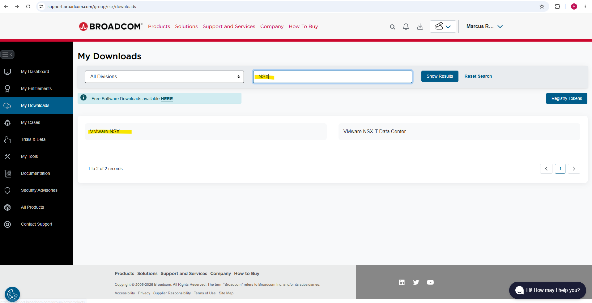
Select VMware NSX.
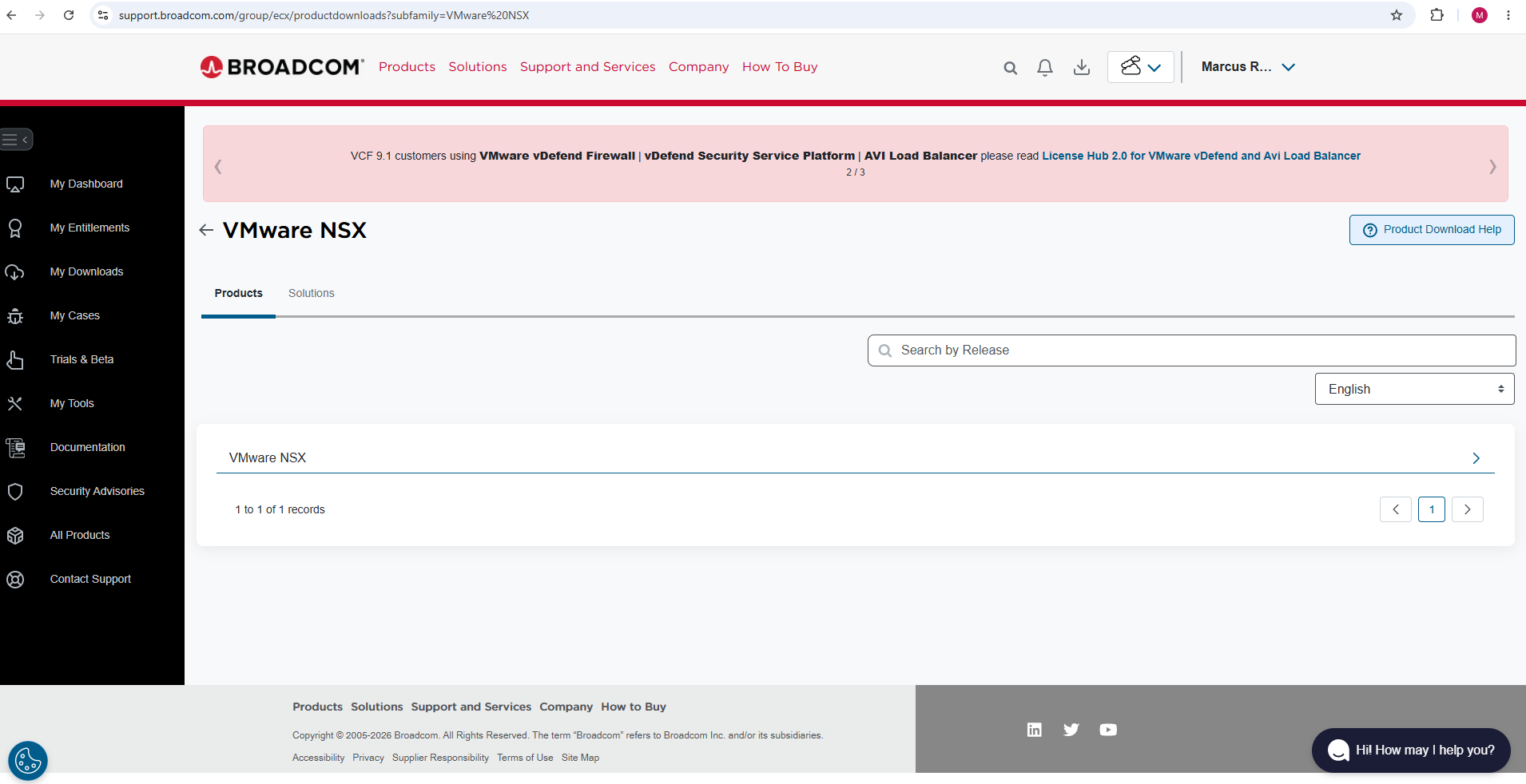
As mentioned, I will use for this series VMware NSX 4.2.4.1.
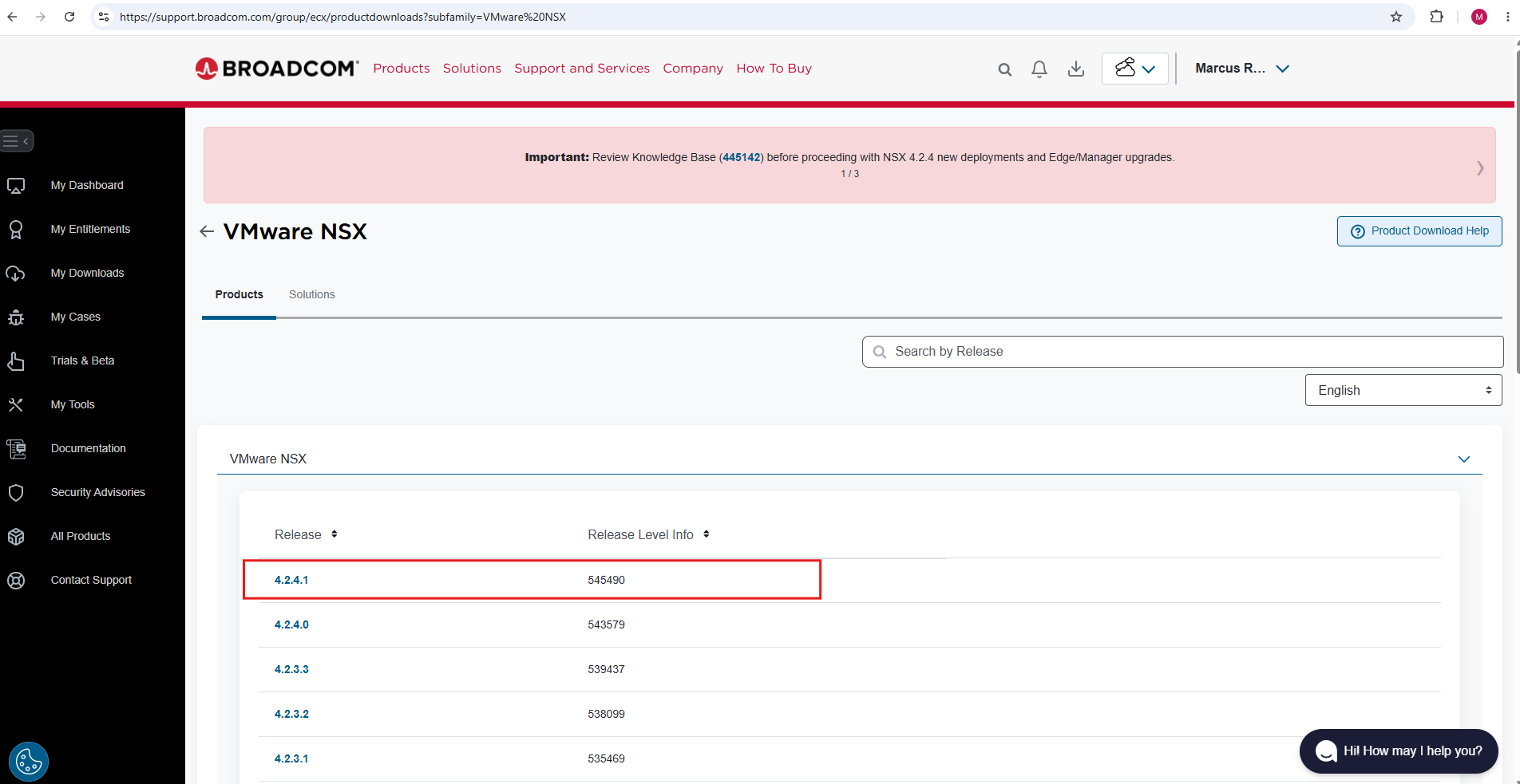
For this deployment, we download the NSX Unified Appliance for VMware ESXi, which contains the NSX Manager used to manage and configure the NSX environment.
In our case, we use VMware NSX 4.2.4.1 (Build 25554964).
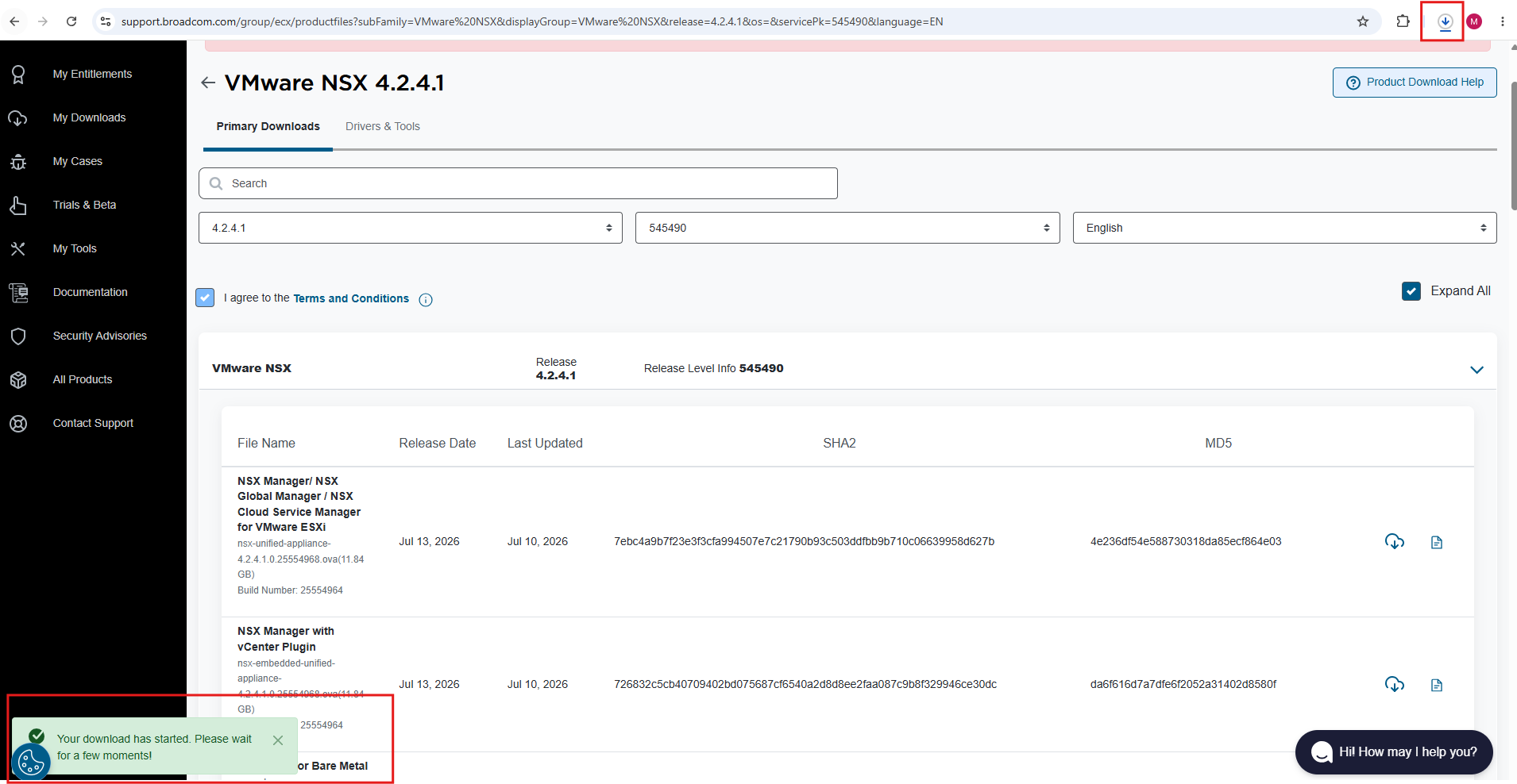
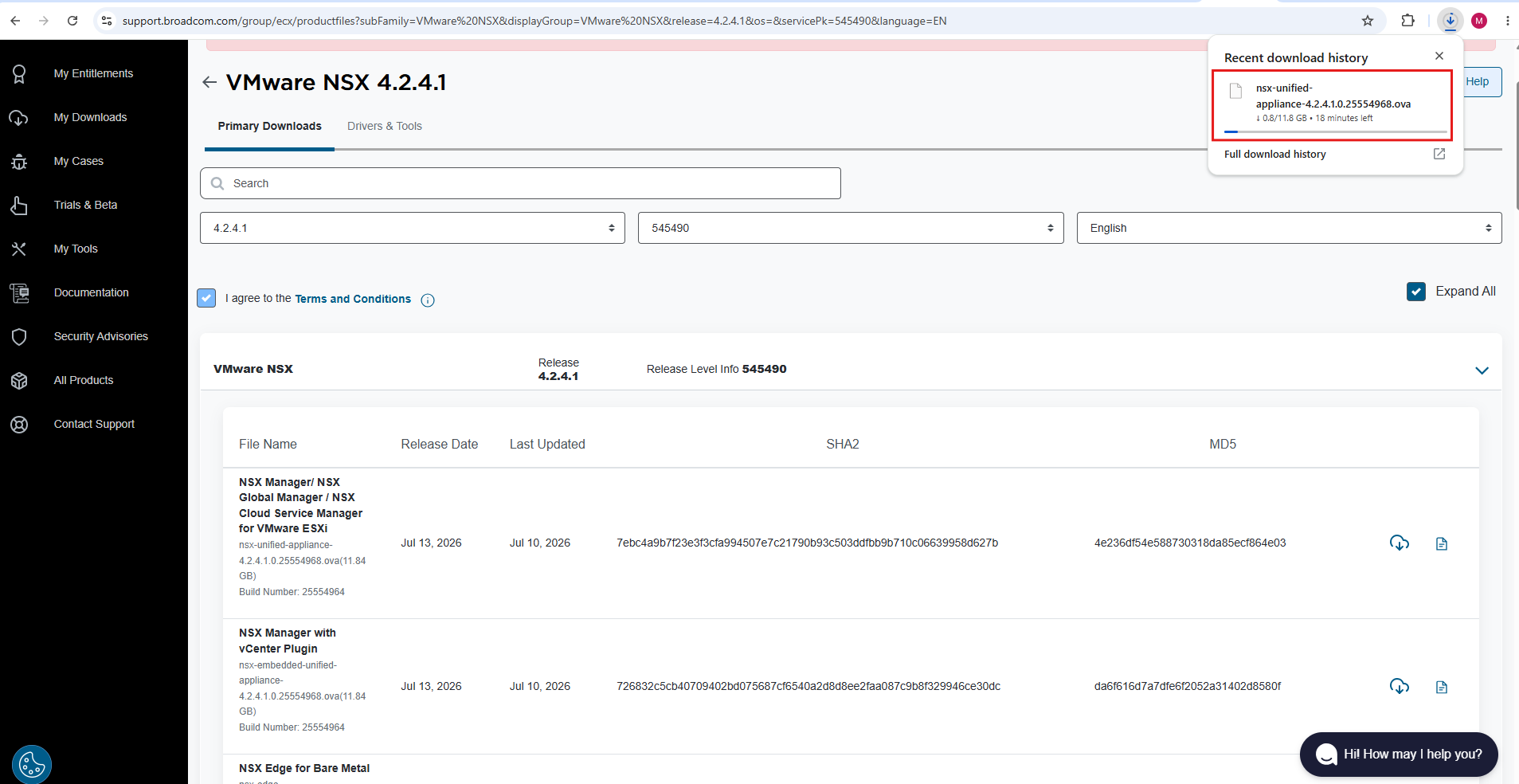
After downloading the NSX Unified Appliance OVA, we can deploy the first NSX Manager directly through the vSphere Client using Deploy OVF Template.
For a lab environment, a single NSX Manager appliance is sufficient, while production environments typically use a three-node NSX Manager cluster for high availability.
Additional Manager nodes can be deployed and added to the cluster through the NSX Manager after the initial appliance has been installed.
Deploy the VMware NSX Manager Appliance in vSphere
We can now deploy the NSX Manager appliance directly into our vSphere environment using the Deploy OVF Template wizard. During the deployment, we will configure the appliance resources, management network, hostname, and initial credentials.
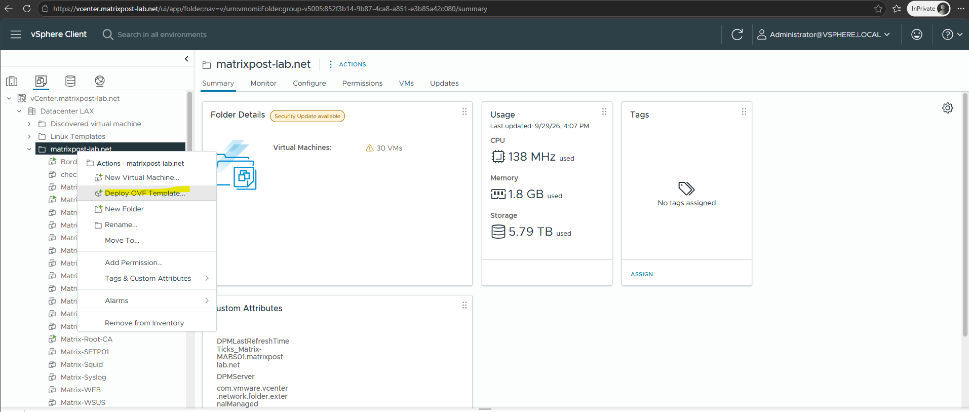
In the vSphere Client, navigate to the inventory location where the NSX Manager appliance should be deployed, right-click it, and select Deploy OVF Template. This starts the deployment wizard for importing the downloaded NSX Unified Appliance OVA.
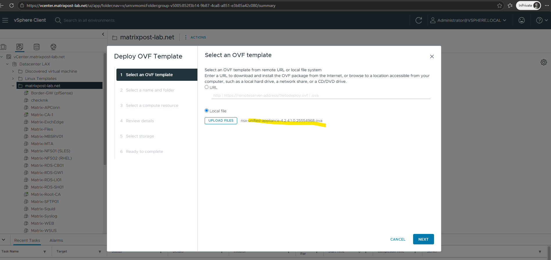
In the Deploy OVF Template wizard, select Local file and upload the previously downloaded NSX Unified Appliance OVA. The wizard will then guide us through the deployment and initial configuration of the NSX Manager appliance.
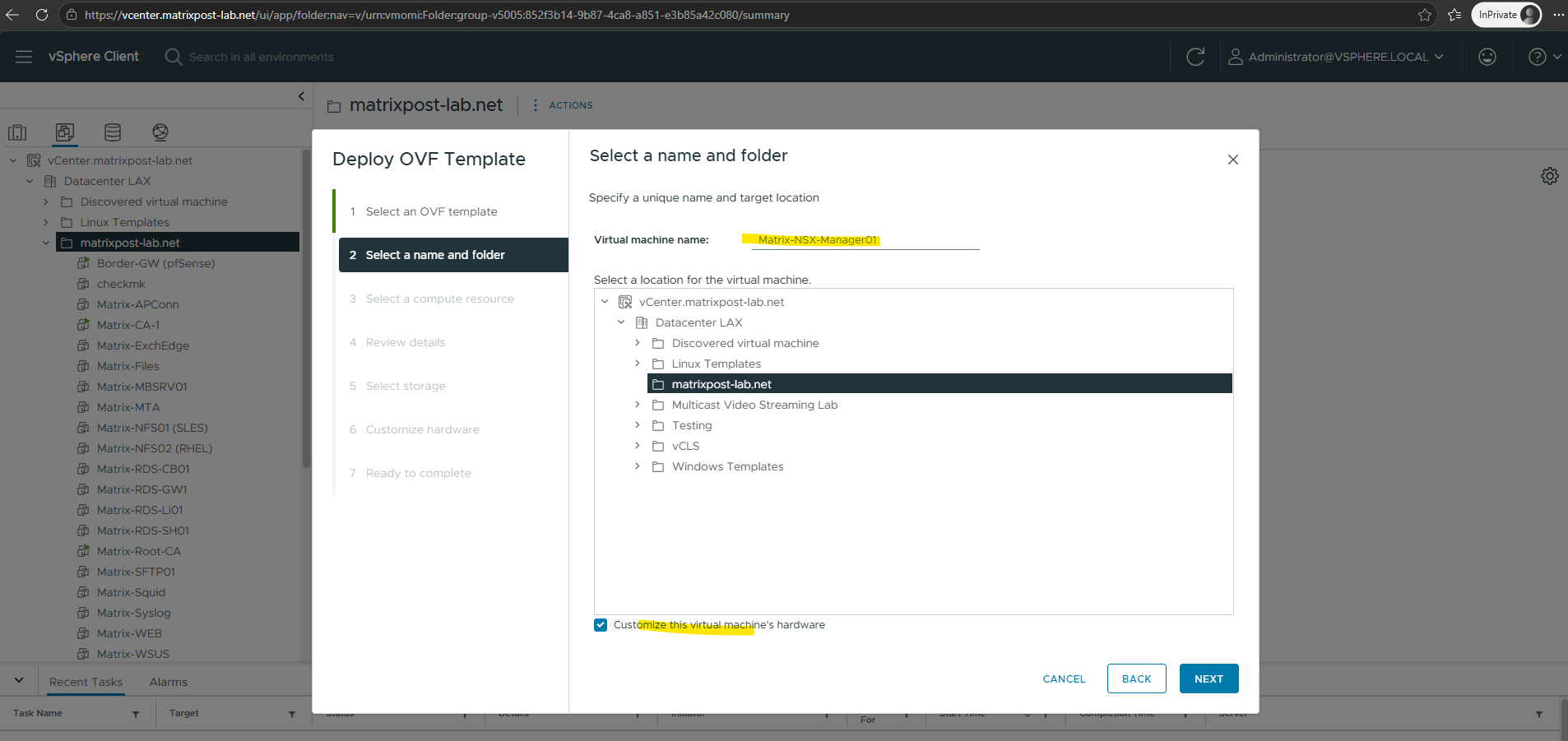
Specify a descriptive name for the NSX Manager virtual machine and select the desired inventory folder.
In my lab, we will use Matrix-NSX-Manager01, which also leaves room for adding additional Manager nodes later.
Additionally, enable Customize this virtual machine’s hardware so we can review the CPU and memory resources assigned by the OVA and avoid unnecessarily allocating resources in my lab environment.
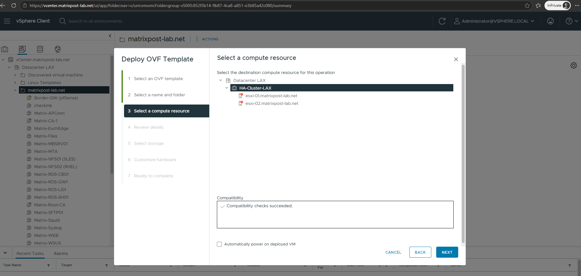
Select the cluster or ESXi host on which the NSX Manager appliance should run. In my lab, we select the HA-Cluster-LAX, allowing vSphere to place the appliance on one of the available ESXi hosts; the compatibility check confirms that the selected compute resource supports the appliance.
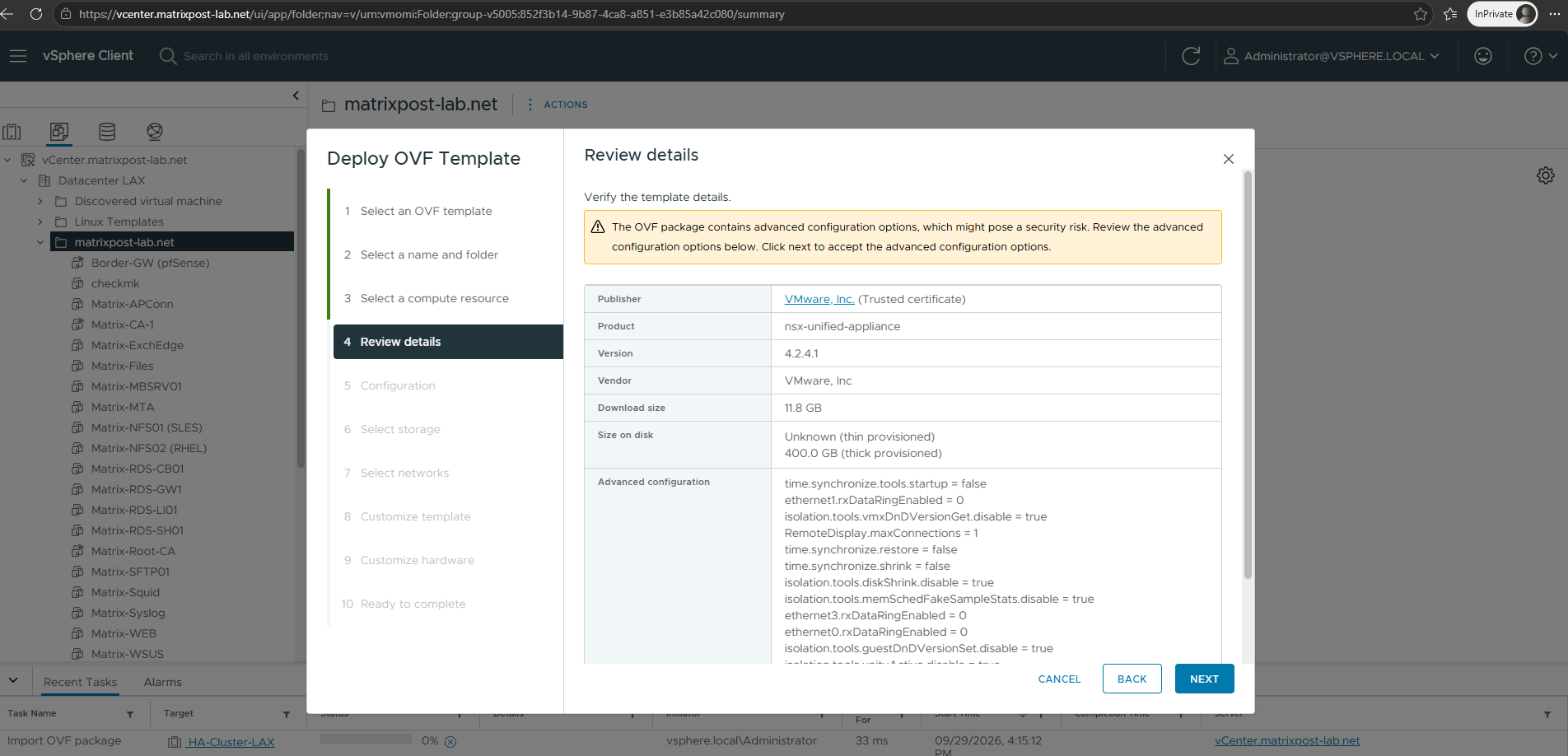
Review the appliance details and verify the publisher, product, and version before continuing. The NSX OVA contains several advanced virtual machine configuration options, which causes vSphere to display a security warning; since the appliance is signed by VMware, Inc. with a trusted certificate, we can review and accept these settings to continue.
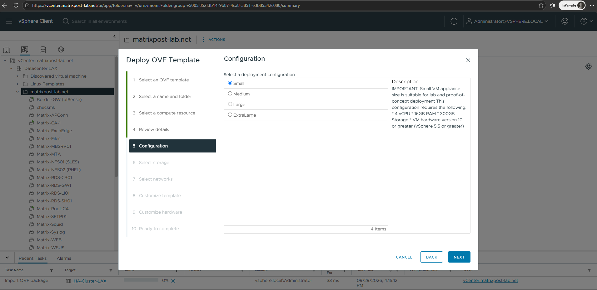
Select the appropriate deployment configuration for the NSX Manager appliance.
Although Medium is selected by default, for my lab environment I will use the Small configuration, which is specifically intended for lab and proof-of-concept deployments and requires 4 vCPUs, 16 GB RAM, and 300 GB of storage.
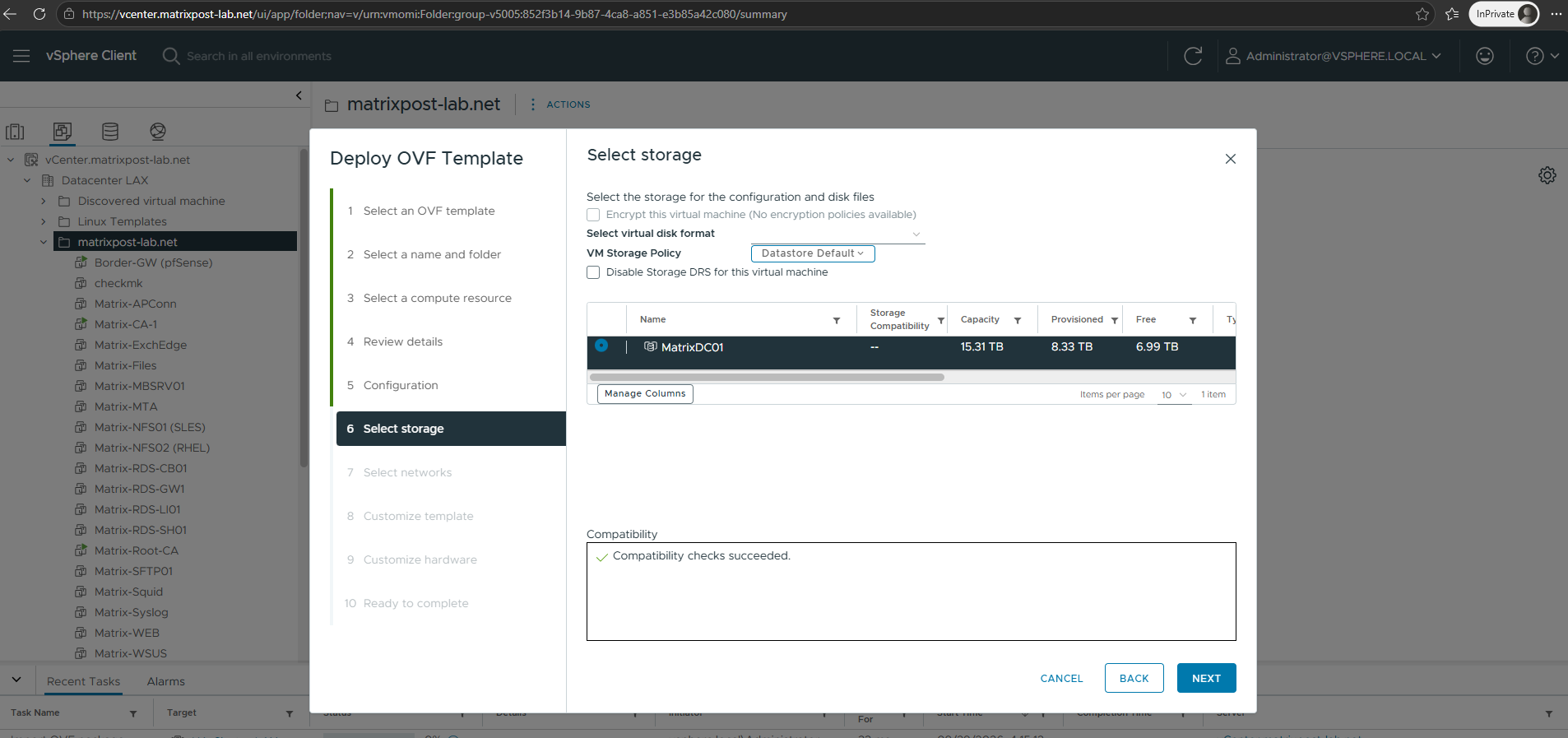
Select the datastore on which the NSX Manager appliance should be deployed.
For my lab environment, I will use Thin Provision for the virtual disks so that the configured 300 GB capacity is allocated dynamically rather than consuming the entire space immediately.
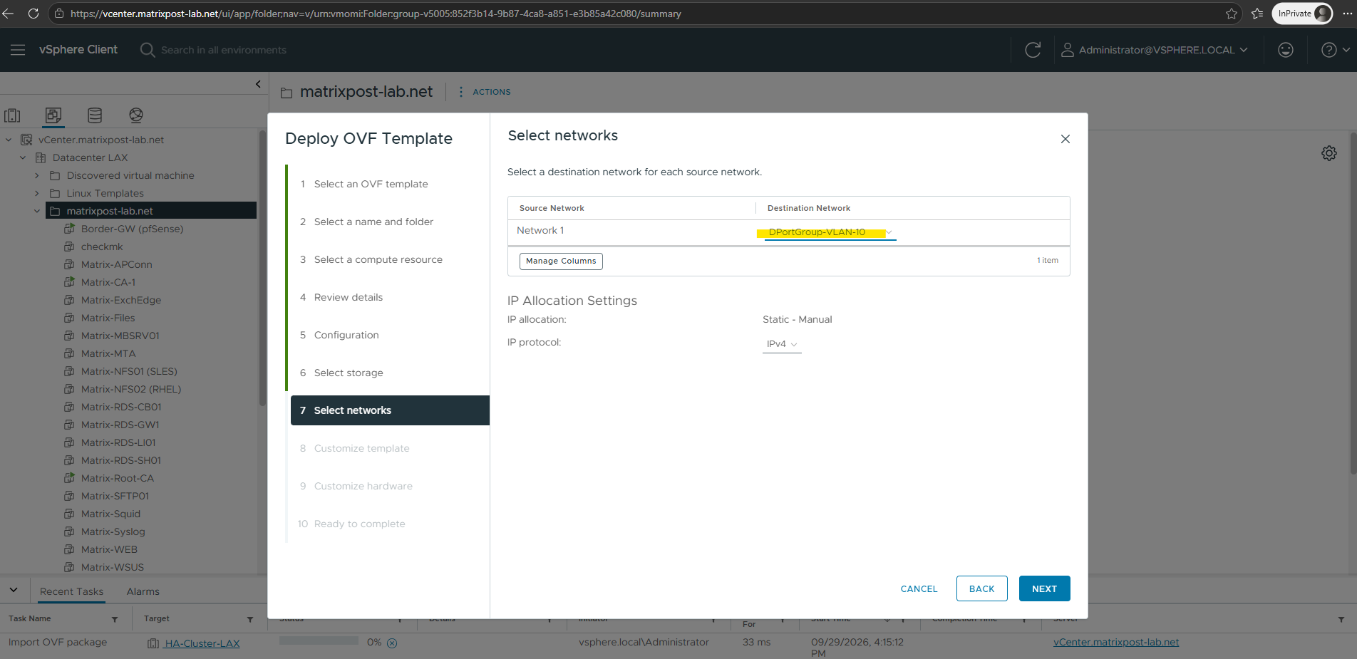
Select the destination network for the NSX Manager management interface.
In my lab, I will use DPortGroup-VLAN-10 on the existing 10.0.0.0/24 management network, which provides connectivity to vCenter, the ESXi hosts, DNS, NTP, and the other infrastructure services.
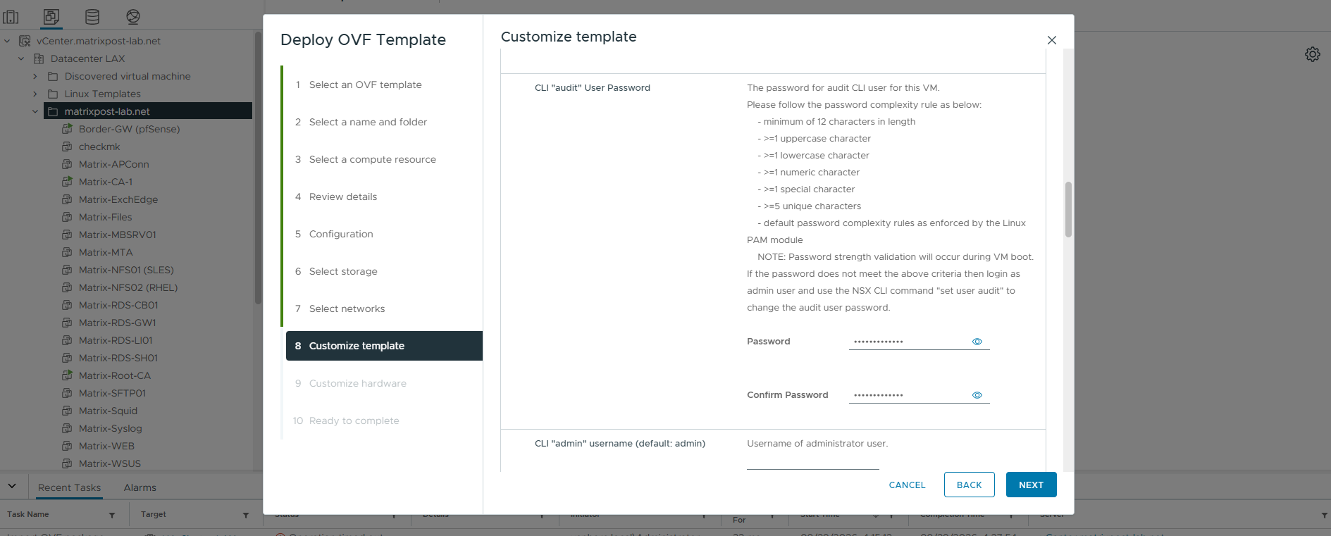
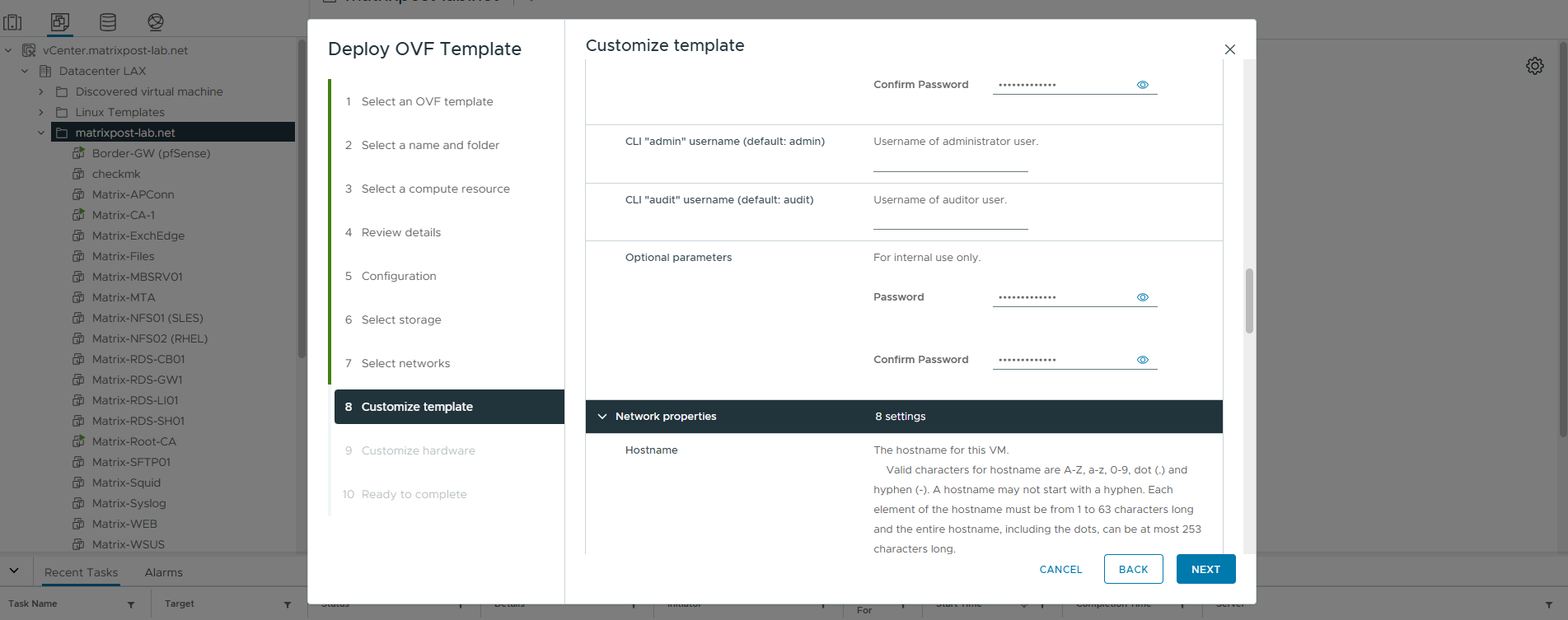
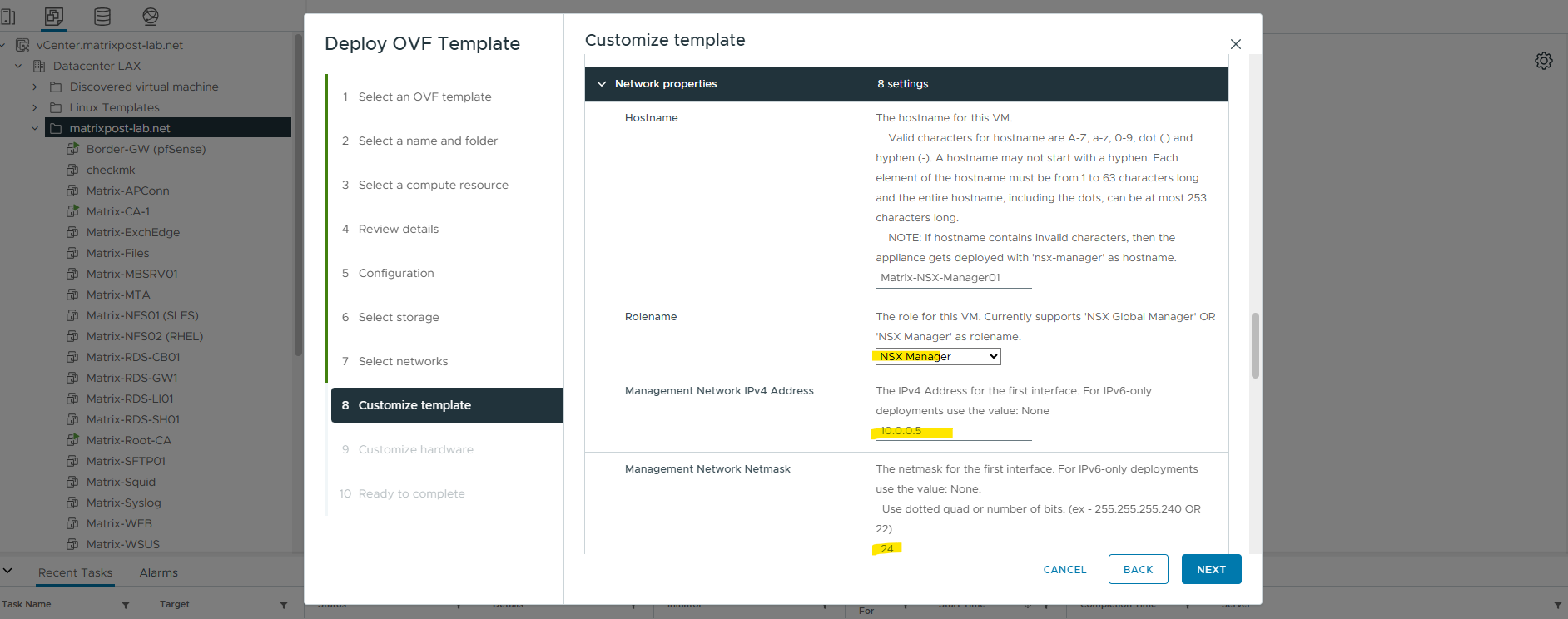
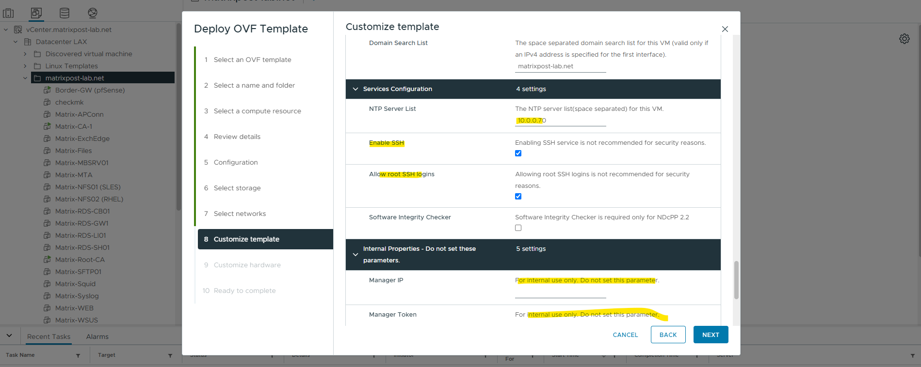
Configure the NSX Manager hostname, management IP address, default gateway, DNS and NTP settings and define the passwords for the appliance accounts.
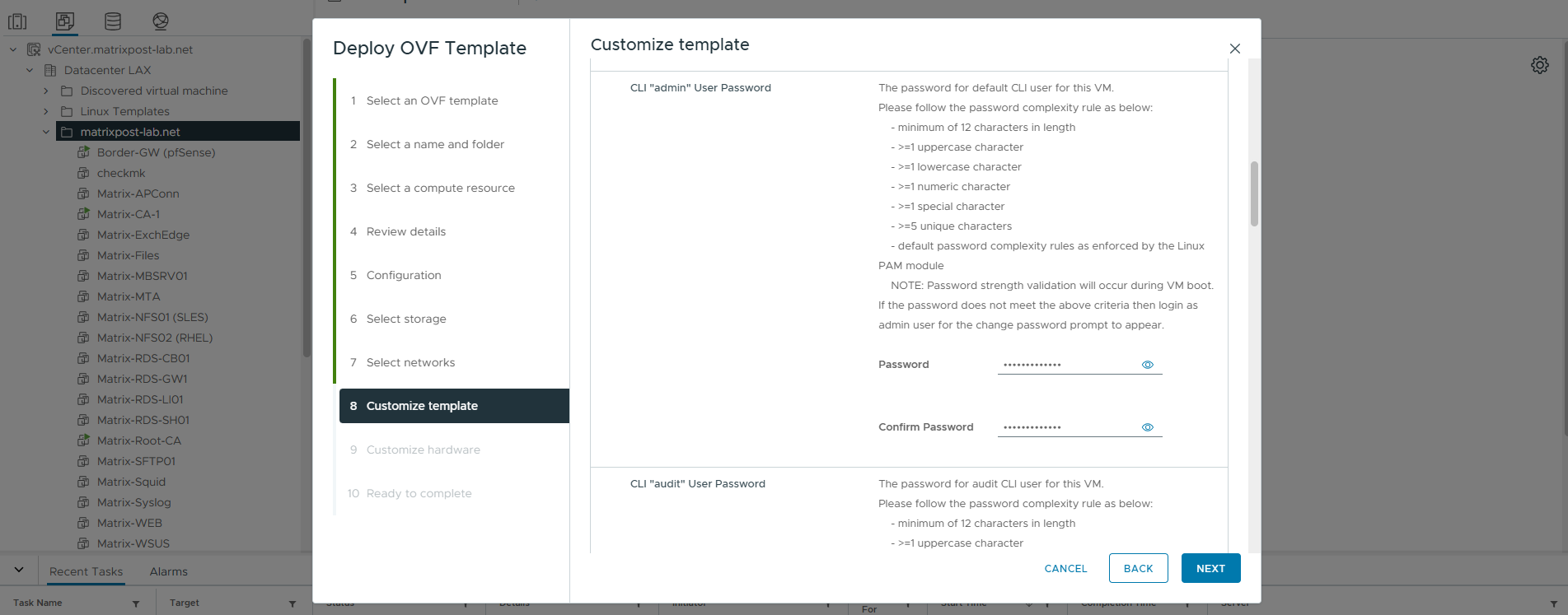
NSX Manager requires separate passwords for the GRUB bootloader, the Linux root account, and the NSX CLI accounts (
adminandaudit). For this lab environment, the same password is used for all accounts for simplicity; separate passwords should be used in production environments.GRUB root password → protects access to the GRUB bootloader. This prevents someone with VM-console access from casually modifying boot parameters to bypass appliance security like shown in my article here for example about resetting the root password https://blog.matrixpost.net/how-to-reset-forgotten-or-not-knowing-root-password-for-linux-by-using-the-grub-boot-loader/.
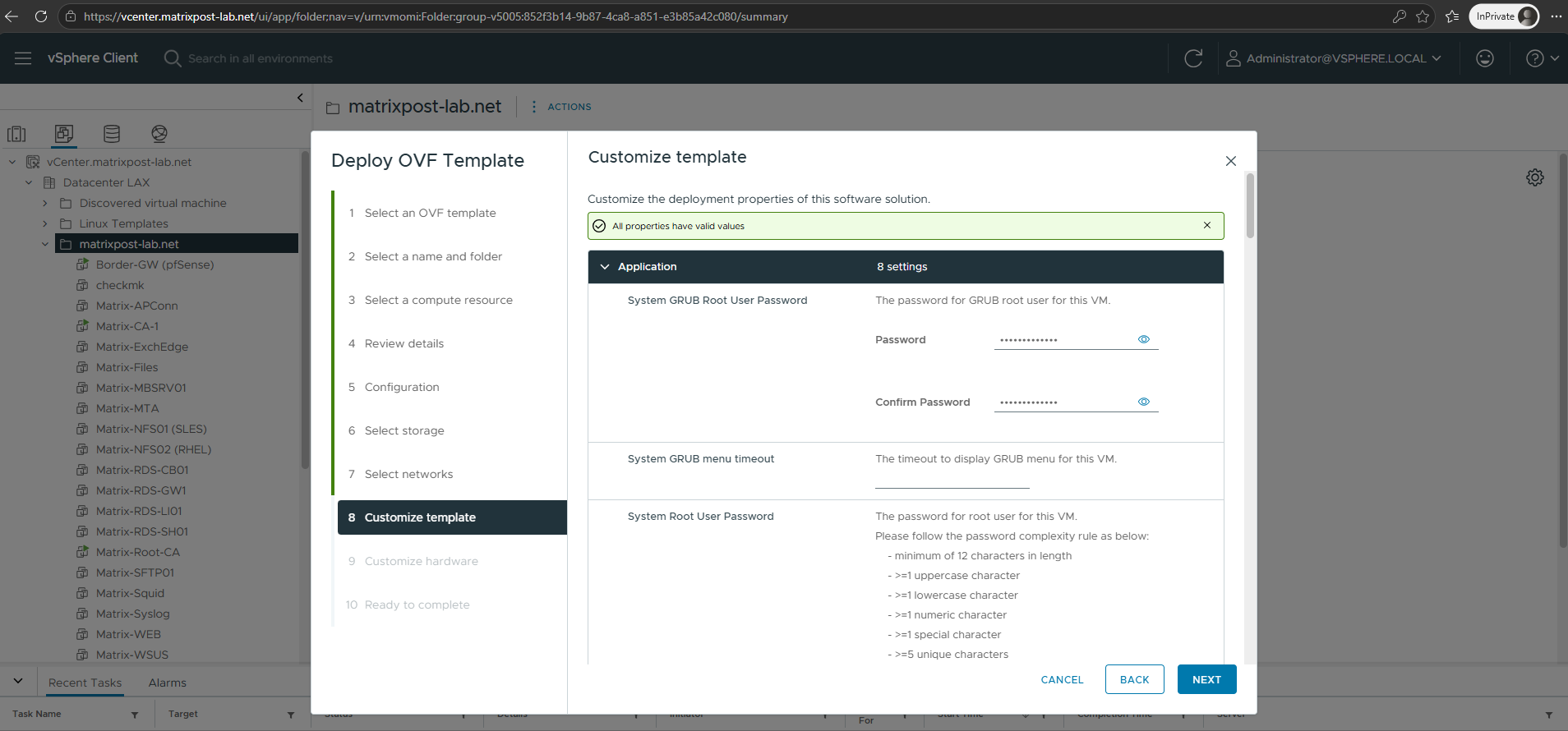
- GRUB root password → protects access to the GRUB bootloader. This prevents someone with VM-console access from casually modifying boot parameters to bypass appliance security.
- System root password → Linux
rootaccount of the NSX Manager appliance. - CLI
adminpassword → the normal NSX administrative CLI account. - CLI
auditpassword → restricted account intended for auditing/log access.
Select NSX Manager as the appliance role.
NSX Global Manager is used with NSX Federation to centrally manage NSX deployments across multiple locations and is not required for our single-site lab environment.
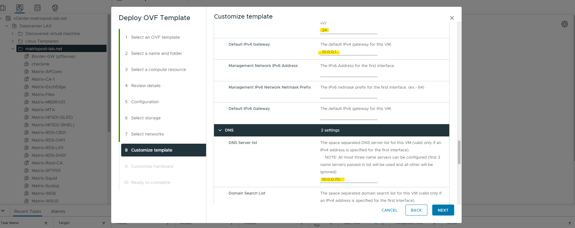
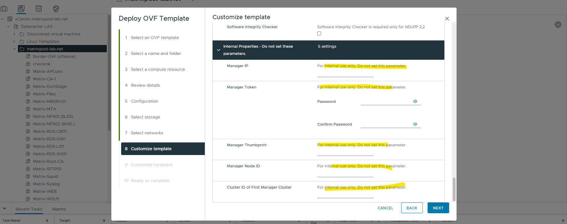
The parameters under Internal Properties – Do not set these parameters are reserved for internal deployment workflows and should be left unchanged when deploying the first standalone NSX Manager appliance.
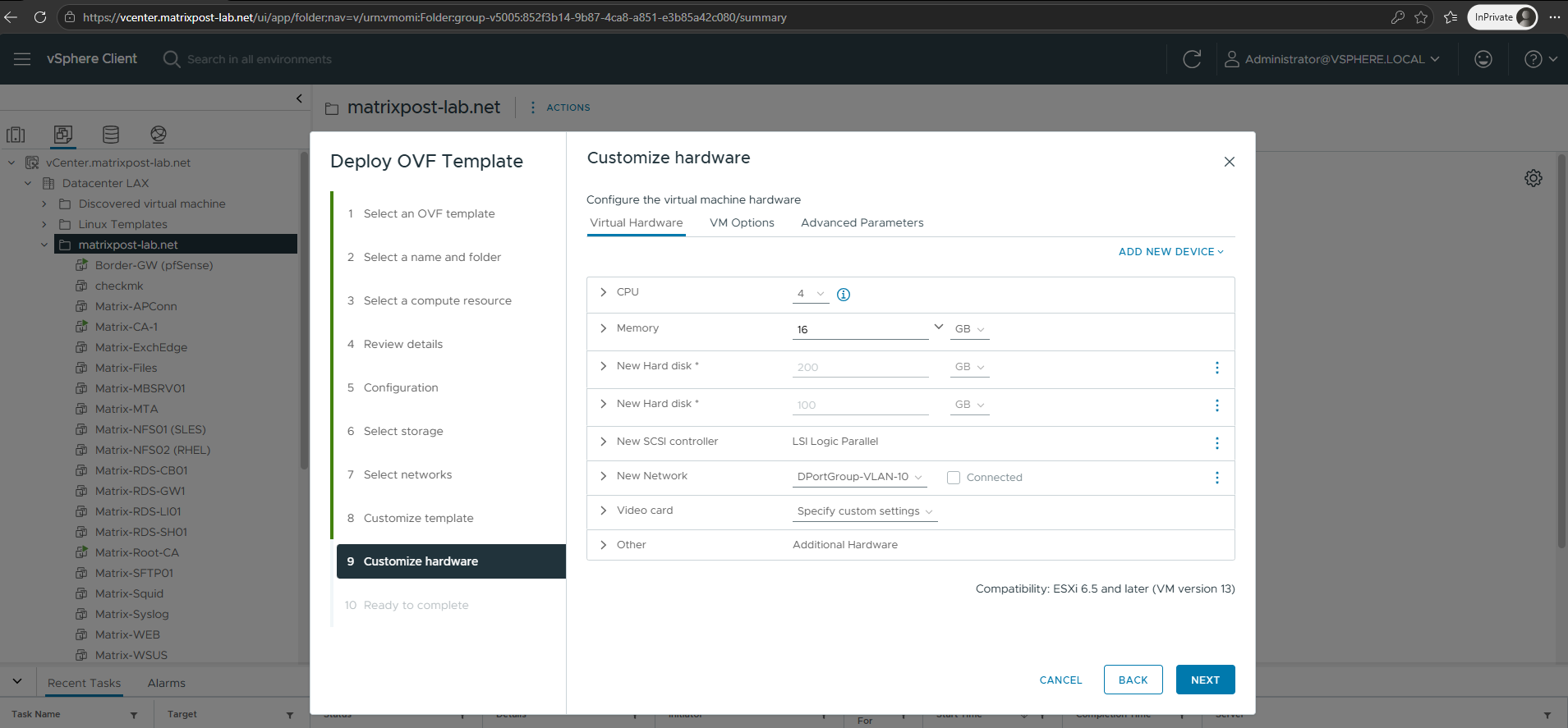
The Small deployment configuration results in an NSX Manager appliance with 4 vCPUs, 16 GB RAM, and two virtual disks (200 GB and 100 GB). These settings are suitable for my lab environment and are therefore left unchanged.
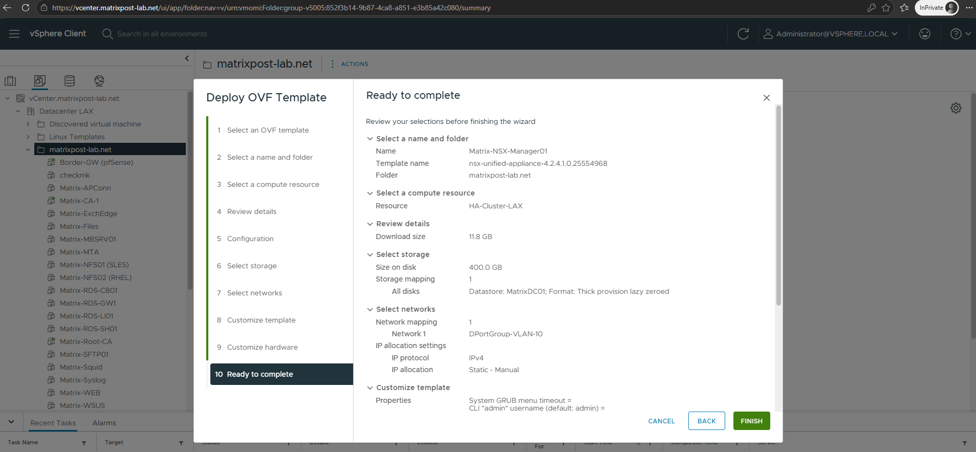
Finally, review the configured deployment settings, including the compute resource, datastore, network mapping, and appliance customization. If all settings are correct, click Finish to start the deployment of the NSX Manager appliance.
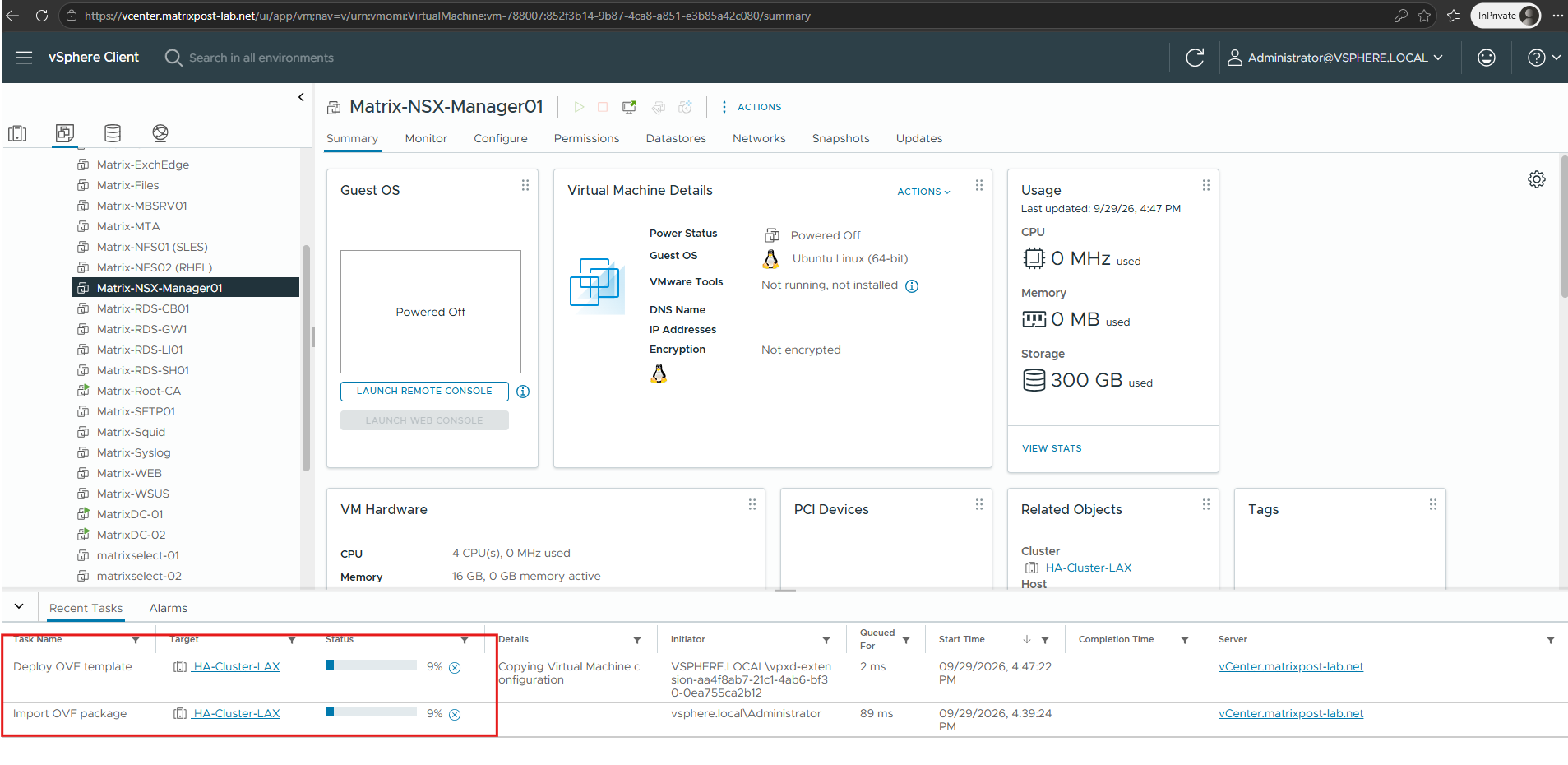
After clicking Finish, vCenter imports the OVA and creates the Matrix-NSX-Manager01 virtual machine.
Wait until the OVF deployment has completed before powering on the NSX Manager appliance.
Start and Access the VMware NSX Manager
Once the OVF deployment has completed, power on the NSX Manager appliance and allow several minutes for its services to initialize. We can then verify the configured management IP and access the NSX Manager web interface for the initial configuration.
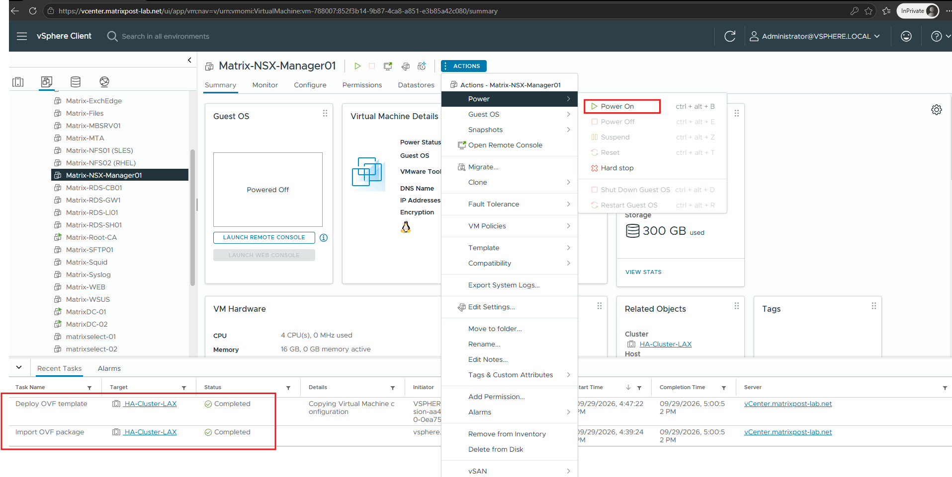
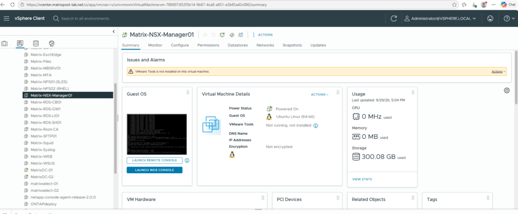
After powering on the appliance, NSX Manager performs its initial boot and starts the underlying operating system and NSX services.
The first startup can take several minutes, so wait until the appliance has fully initialized before accessing the management interface.
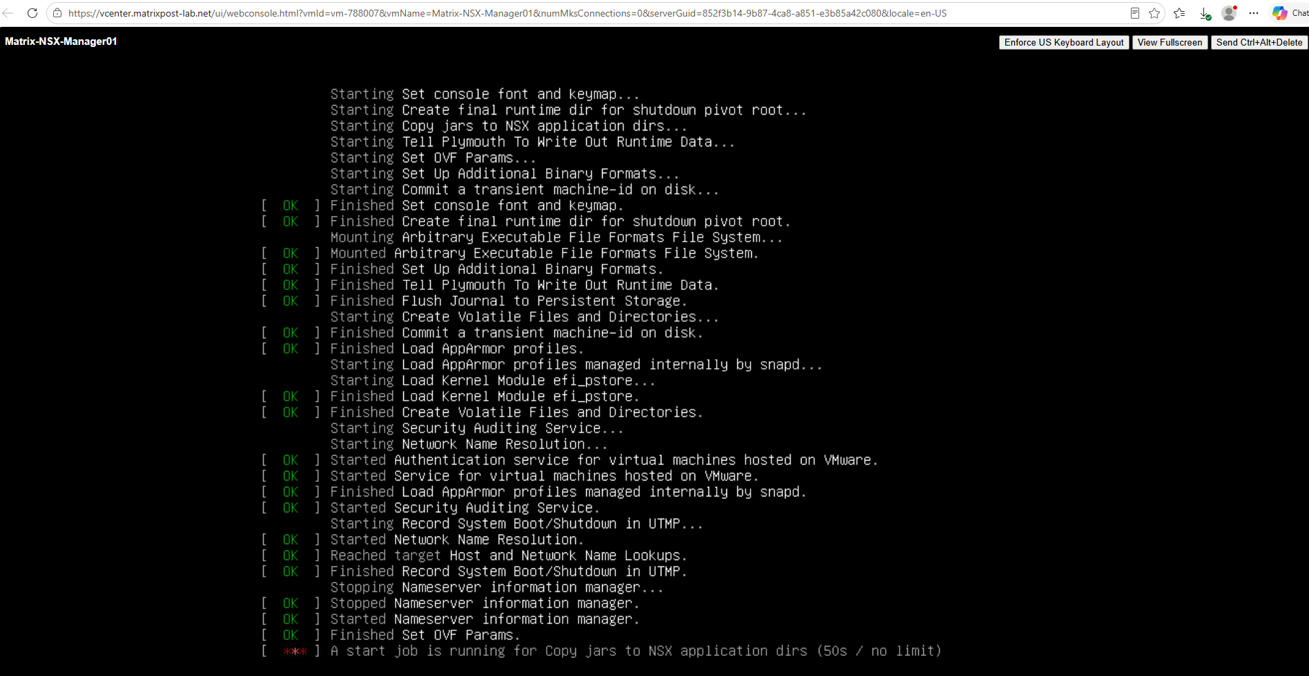
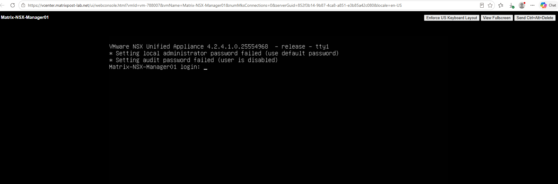
Once the initialization has completed, the NSX Manager console login is displayed.
At the console login, the previously configured password for the
adminuser did not work for whatever reason.
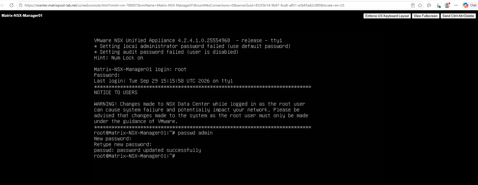
Since the root password worked, I logged in as root and reset the password for the admin account using:
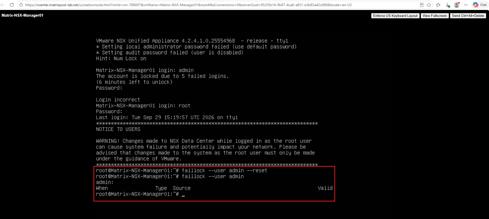
We can also reset the lockout, we can verify the account status using faillock --user admin.
An empty list of failed attempts confirms that the previous login failures have been cleared and the
adminaccount is no longer locked.
faillock --user admin --reset
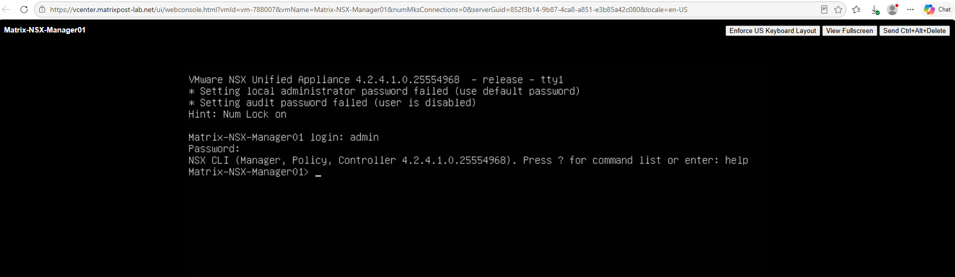
After clearing the failed login attempts, I was able to successfully log in with the admin account and the newly configured password.
The login opens the NSX CLI (Manager, Policy, Controller), confirming that the administrative account is working correctly.
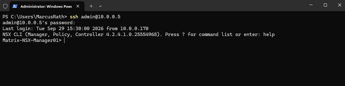
Once the admin account was working again, I could also connect to the NSX Manager remotely via SSH.
The SSH session opens the same NSX CLI, which we can use to manage and troubleshoot the appliance from the command line.
ssh admin@10.0.0.5
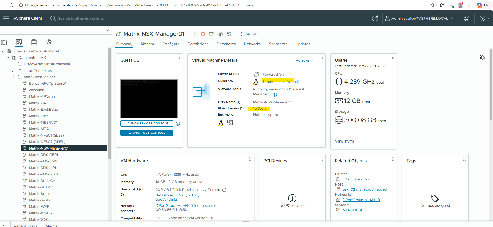
Once NSX Manager has finished booting, vCenter shows the appliance running on Ubuntu Linux (64-bit) with the configured management IP address 10.0.0.5 and its network adapter connected to DPortGroup-VLAN-10.
We can now access the NSX Manager web interface using this address.
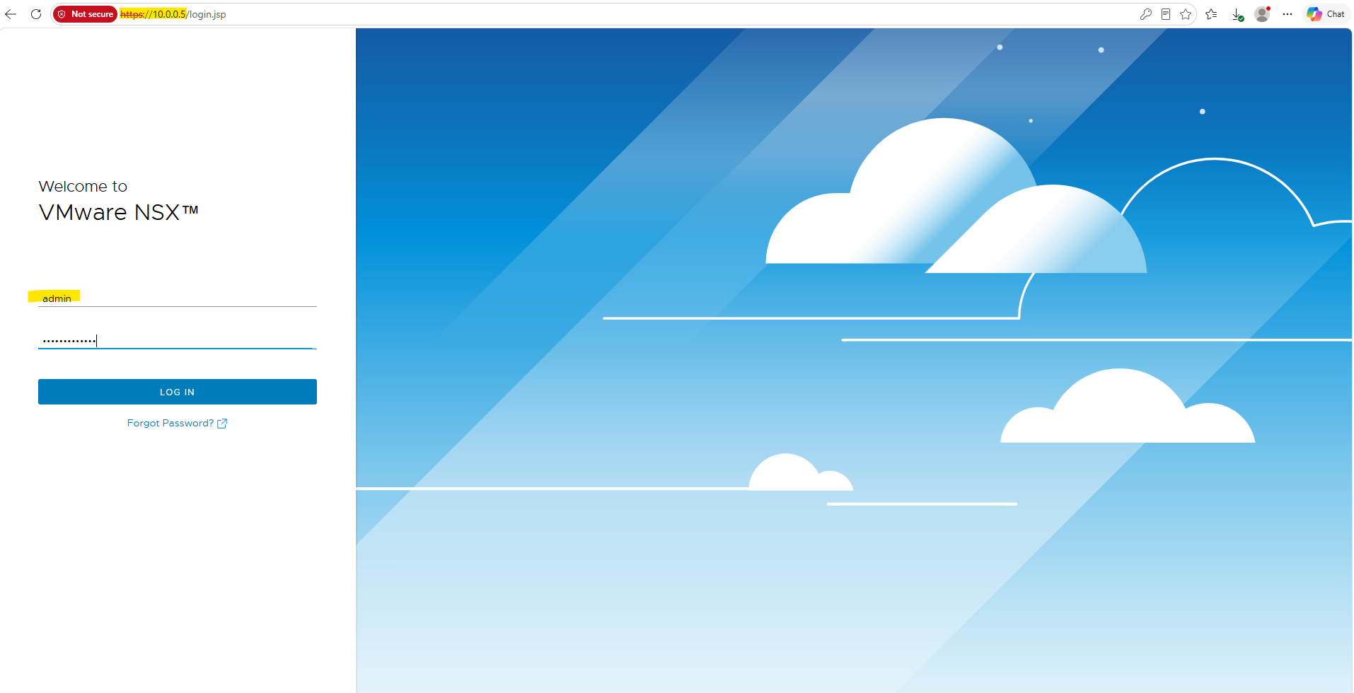
After the initial deployment, the NSX Manager web interface may take several additional minutes to become available while the NSX services are initialized.
Once initialization has completed, we can access the management interface via
https://<NSX-Manager-IP>and log in with theadminaccount.
After logging in to the NSX Manager web interface for the first time, it may take another 2–3 minutes for the UI to finish loading completely.

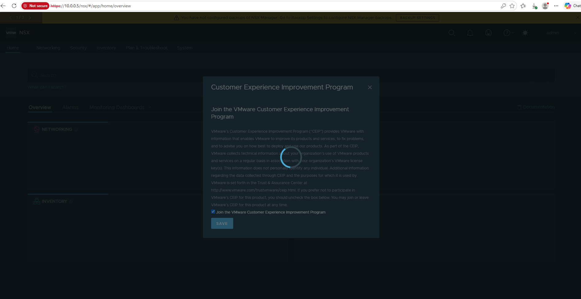
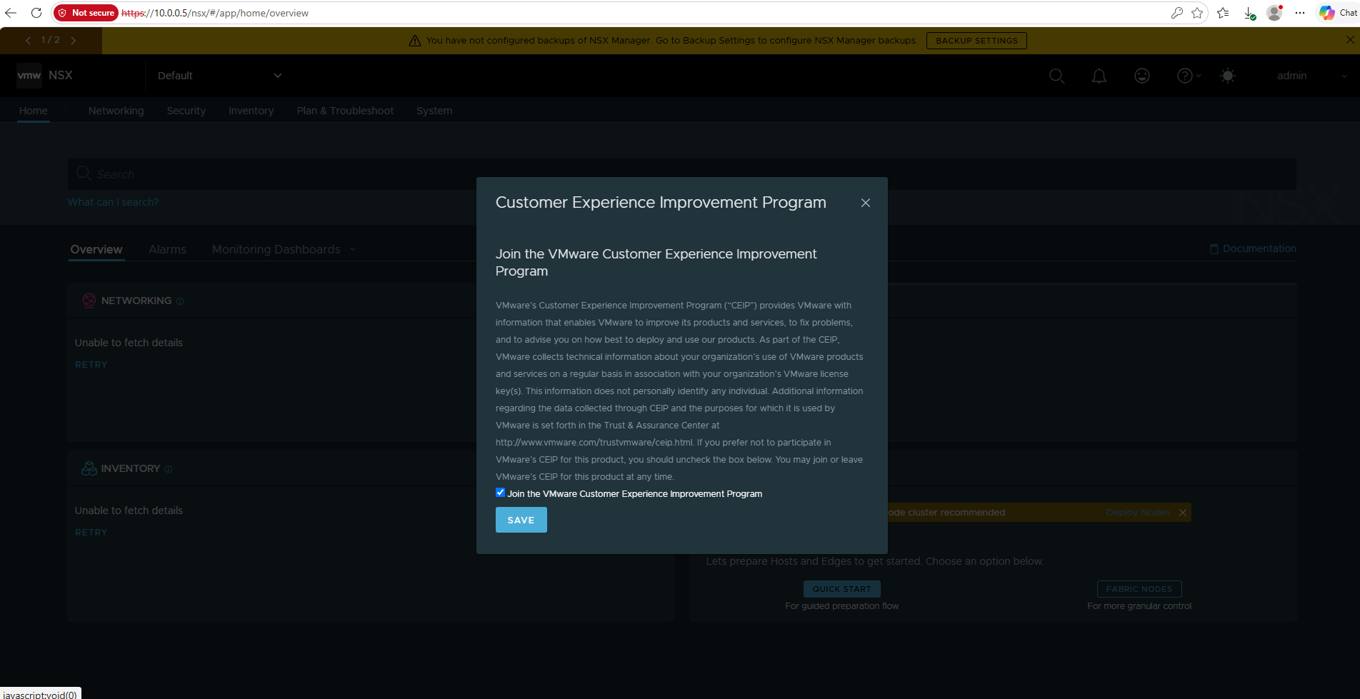
Once initialization is complete, the Customer Experience Improvement Program (CEIP) dialog appears, where we can choose whether to participate before continuing with the NSX configuration.
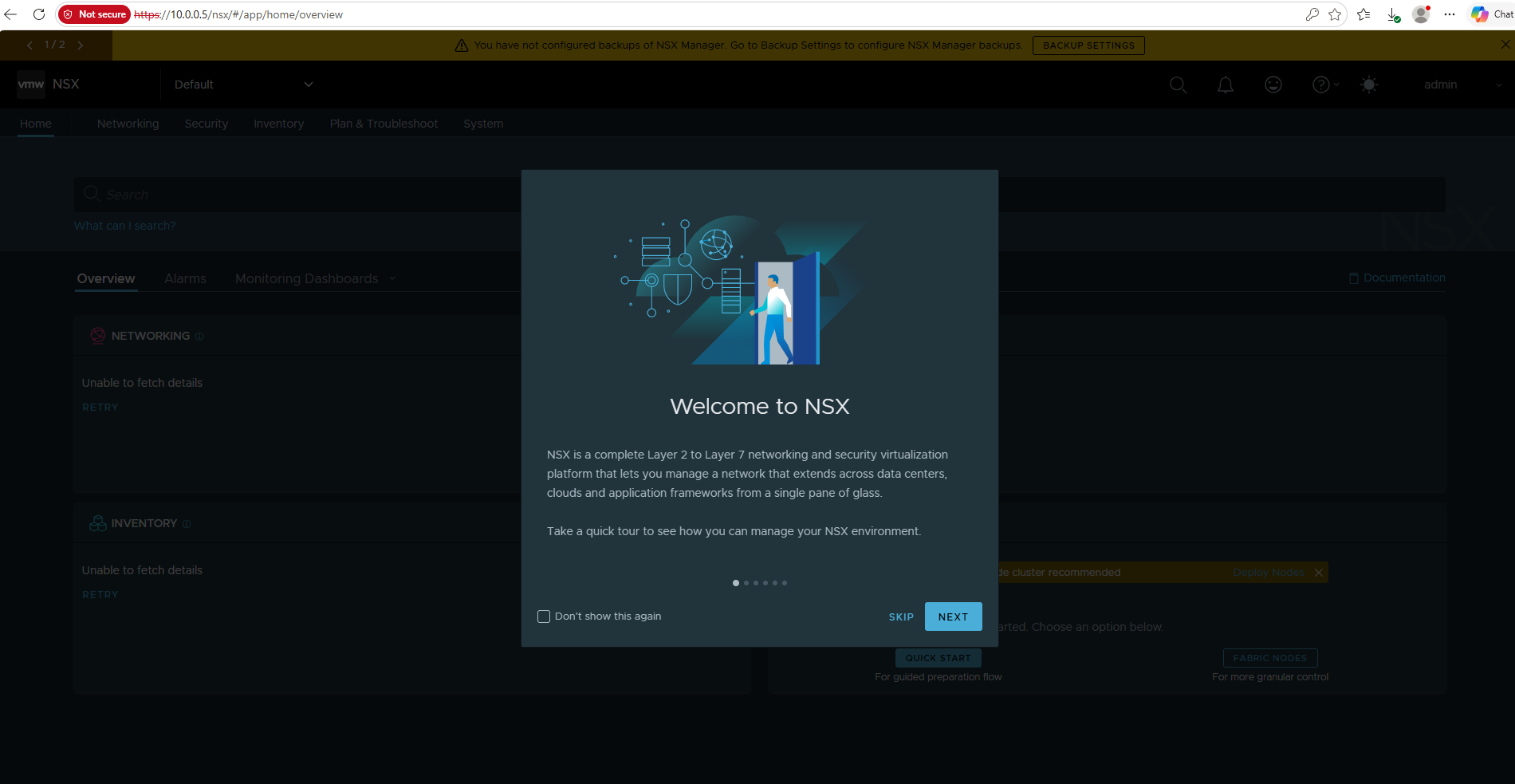
The Welcome to NSX tour provides a brief introduction to the platform and describes NSX as a Layer 2 to Layer 7 networking and security virtualization platform for managing networks across data centers, clouds, and application environments.
We can either walk through the short tour or skip it and continue directly with the configuration.
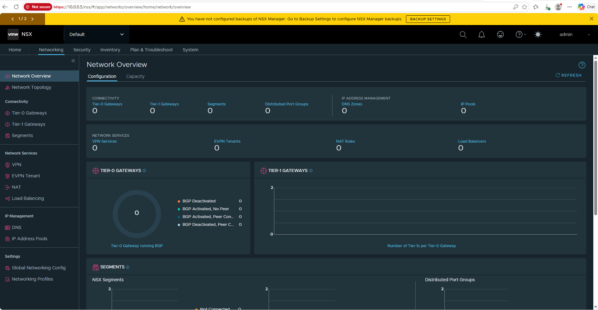
Once the initial dialogs are completed, the NSX Manager interface provides access to the main areas such as Networking, Security, Inventory, Plan & Troubleshoot, and System.
The Network Overview already shows the major NSX components we will configure later, including Tier-0/Tier-1 Gateways, Segments, VPN, NAT, Load Balancing, and IP Address Pools.
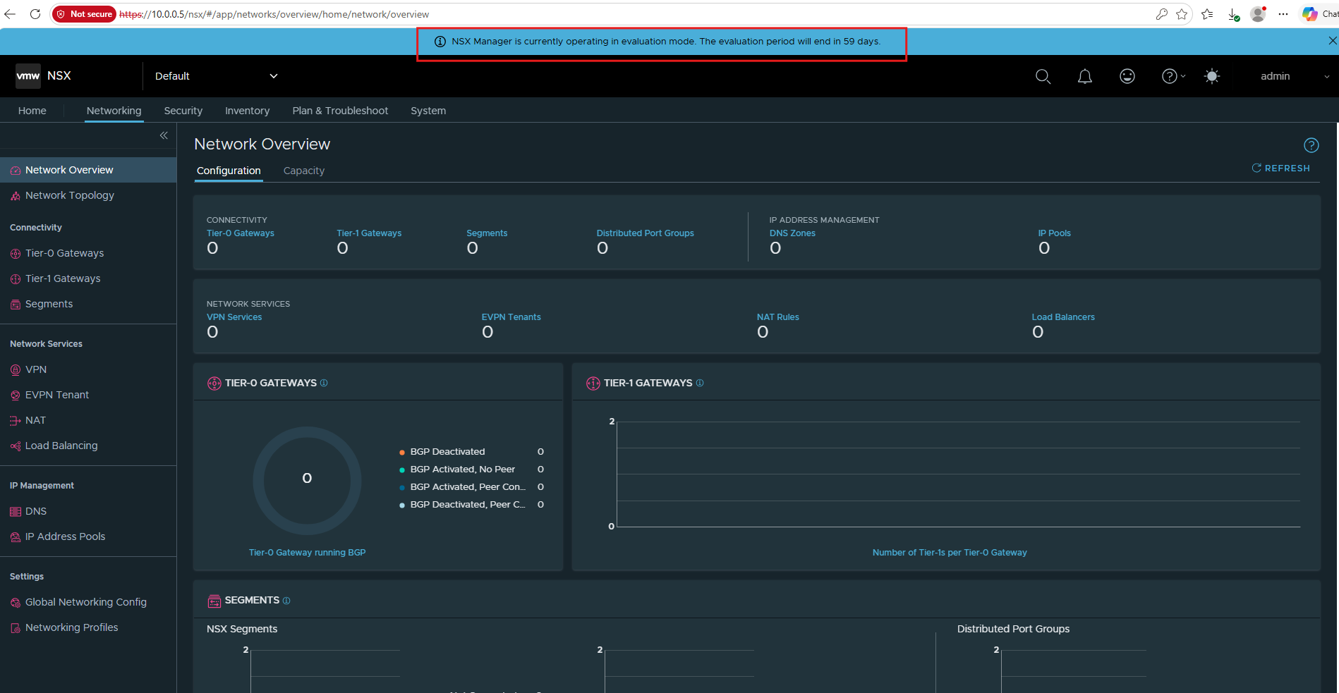
For this lab, the NSX Manager is running in evaluation mode, which provides the required NSX functionality without installing a license key.
The evaluation period is limited to 60 days, with the remaining time displayed directly in the NSX Manager interface.
Connect NSX Manager to vCenter Server
Before we can prepare our ESXi hosts and deploy the NSX networking components, we first need to connect NSX Manager to our vCenter Server.
This integration allows NSX to discover and manage the existing vSphere environment, including its clusters, ESXi hosts, virtual switches, and virtual machines.
Go to System → Fabric → Compute Managers and click Add Compute Manager. In NSX, vCenter is registered as a Compute Manager.
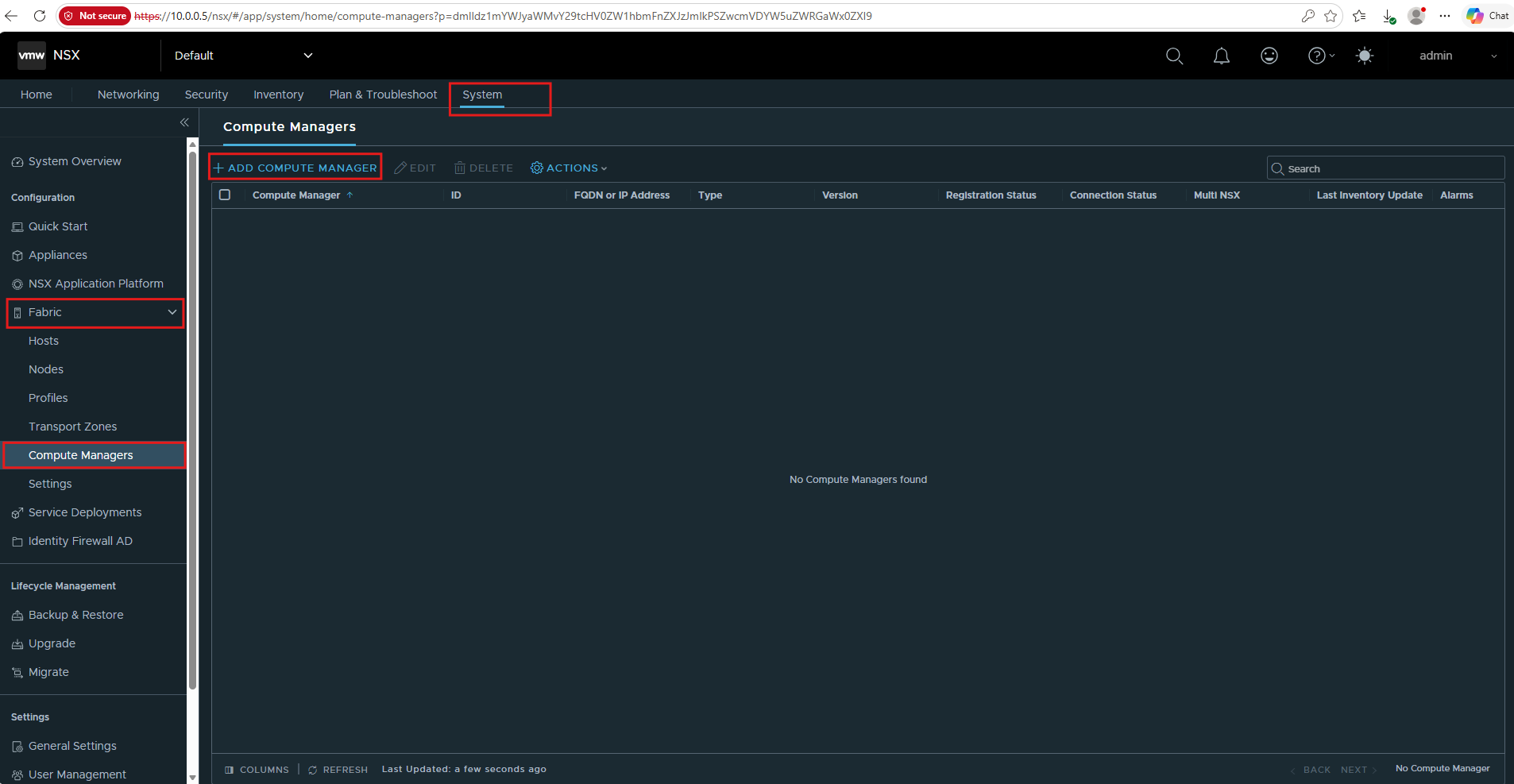
Name:                  Matrix-vCenter
Description:           vCenter Server for the matrixpost lab
Type:                  vCenter
Multi NSX:             No
FQDN or IP Address:    vcenter.matrixpost-lab.net
HTTPS Port:            443
Username:              administrator@vsphere.local
Password:              <vCenter password>
SHA-256 Thumbprint:    <leave empty>
Create Service Account: Yes
Enable Trust: Yes
Access Level: Full Access to NSX
Multi NSX = No because we’re using a single NSX deployment.
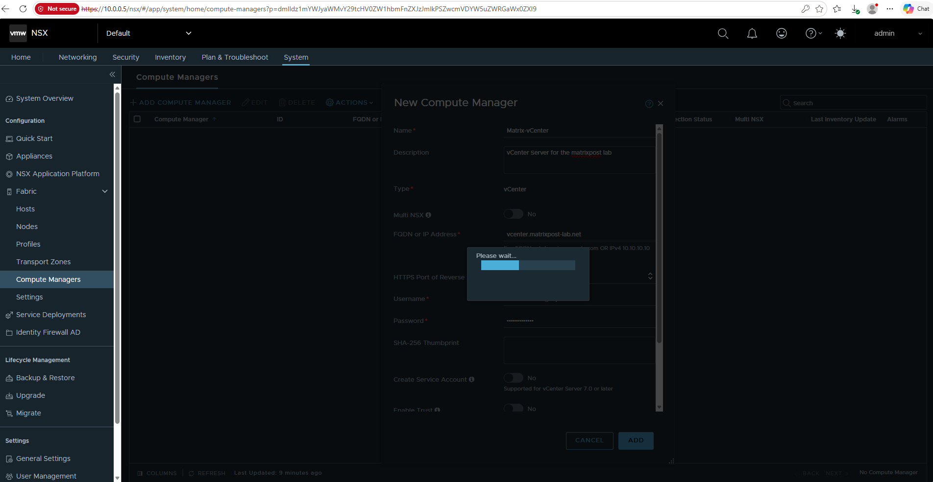
After entering the vCenter Server FQDN and administrator credentials, click Add to register vCenter as an NSX Compute Manager.
NSX now establishes the connection and validates the supplied configuration.
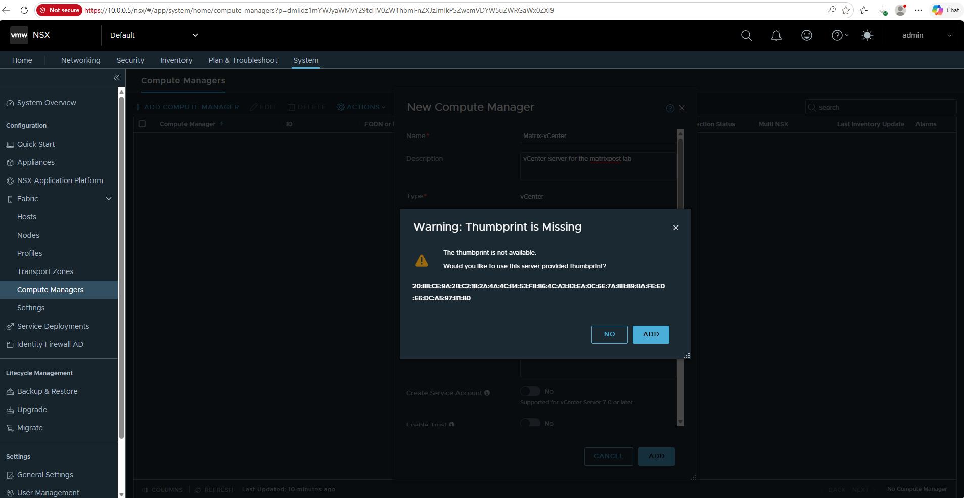
Since we did not specify the SHA-256 certificate thumbprint manually, NSX retrieves it from the vCenter Server and asks us to verify and accept it.
After confirming that the displayed thumbprint belongs to our vCenter Server, click Add to continue.
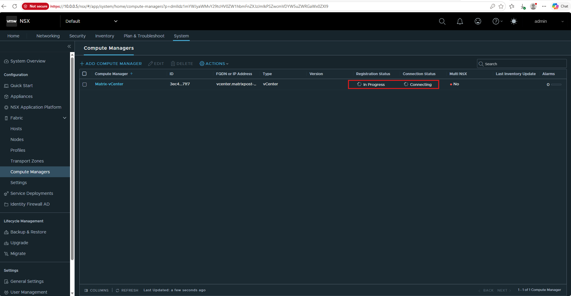
After adding the vCenter Server, NSX begins the registration and connection process.
During this step, the Registration Status shows In Progress and the Connection Status shows Connecting until the integration has been completed.
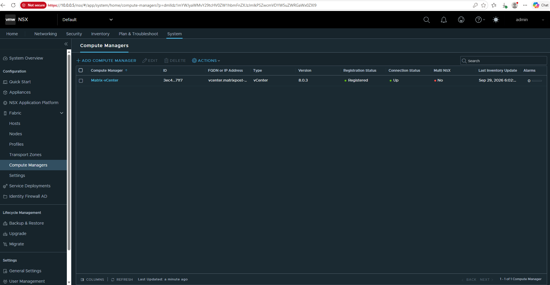
The vCenter Server has now been successfully registered with NSX Manager.
The Registered registration status and Up connection status confirm that the integration is working and the vSphere inventory is accessible to NSX.
Prepare the ESXi Hosts for NSX
Before NSX can provide overlay networking and distributed services, the ESXi hosts must be prepared as NSX Transport Nodes. We will first verify that NSX has discovered our vSphere cluster and hosts and then configure the components required for the NSX transport network.
Go to System → Fabric → Hosts.
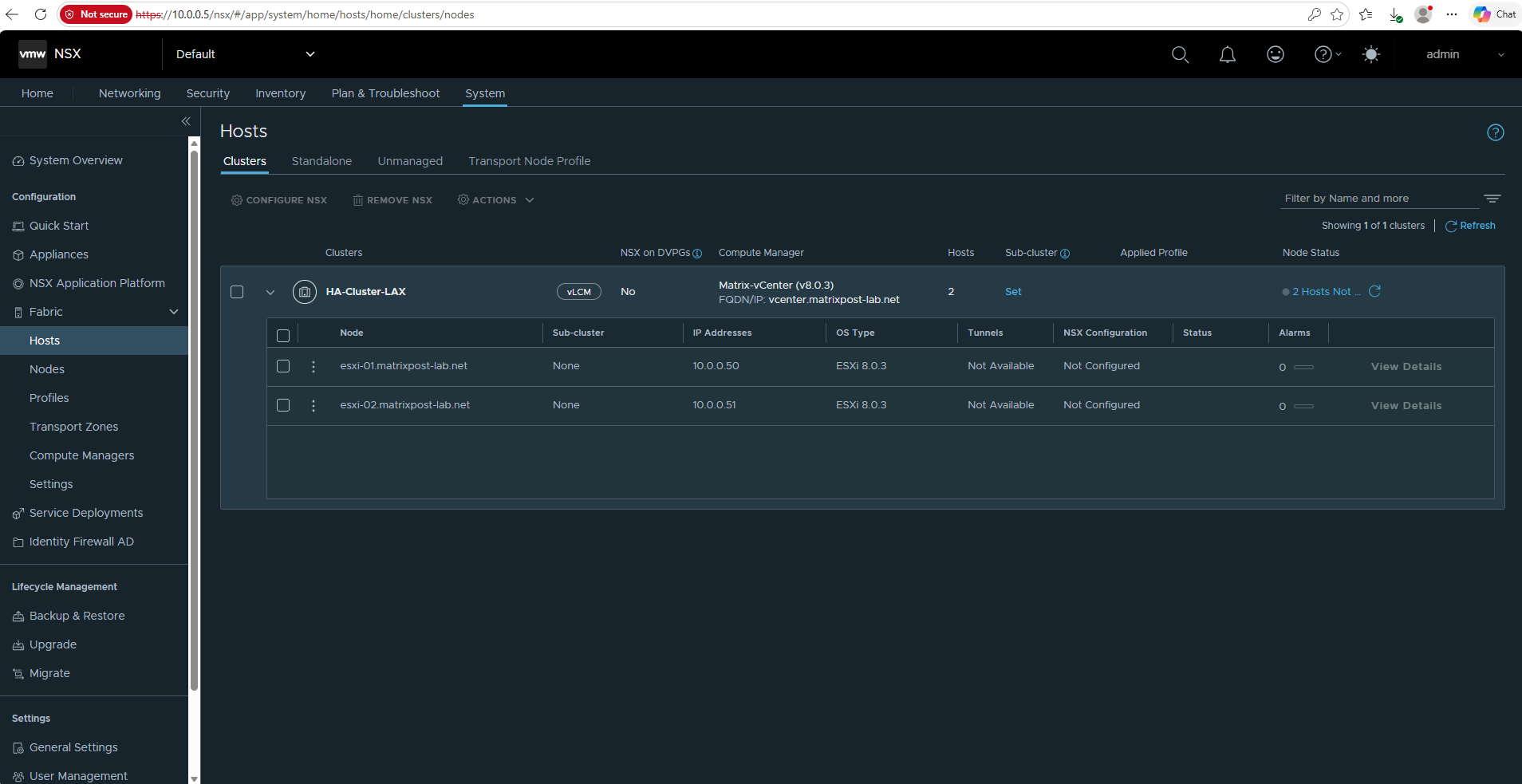
We should now see Datacenter LAX → HA-Cluster-LAX and the ESXi hosts discovered through
Matrix-vCenter.NSX has discovered our HA-Cluster-LAX and both ESXi hosts through the registered vCenter Server. Both hosts currently show NSX Configuration: Not Configured and no tunnels, confirming that they have not yet been prepared as NSX transport nodes.
Before we can prepare the ESXi hosts as NSX Transport Nodes, several components of the NSX transport network must first be configured. We will build these components step by step and finally apply the resulting configuration to our HA-Cluster-LAX.
- Configure the NSX TEP IP Pool – Provides IP addresses for the Tunnel Endpoints (TEPs) used to transport encapsulated overlay traffic between ESXi hosts.
- Configure the Transport Zones – Defines which transport nodes can participate in the NSX overlay and VLAN transport networks.
- Create an Uplink Profile – Defines how the ESXi host uplinks connect to the physical network, including teaming and the transport VLAN.
- Create a Transport Node Profile – Combines the transport zones, uplink configuration, TEP configuration, and host switch settings into a reusable profile.
- Prepare the ESXi Hosts – Apply the Transport Node Profile to HA-Cluster-LAX, causing NSX to install and configure the required components on both ESXi hosts.
- Verify the Transport Nodes – Confirm that both ESXi hosts are successfully configured as NSX Transport Nodes and that their TEP interfaces are operational.
Configure the NSX TEP IP Pool
Before we can prepare the ESXi hosts as NSX Transport Nodes, we first need to provide IP addresses for their Tunnel Endpoints (TEPs). The TEP interfaces are used by the NSX transport nodes to carry encapsulated overlay traffic between hosts.
Conceptually, an NSX TEP IP address serves a similar purpose to the Provider Address (PA) in Microsoft HNV: both provide addresses on the physical underlay network that are used to transport encapsulated overlay traffic between virtualization hosts.
For the equivalent concept in Microsoft HNV, see https://blog.matrixpost.net/hyper-v-network-virtualization-hnv-part1/#verifying_provider_address_allocation.
To create the IP pool for our ESXi host TEP addresses, go to Networking → IP Management → IP Address Pools. From here, we can define the subnet and IP range that NSX will use when assigning TEP addresses to the transport nodes.
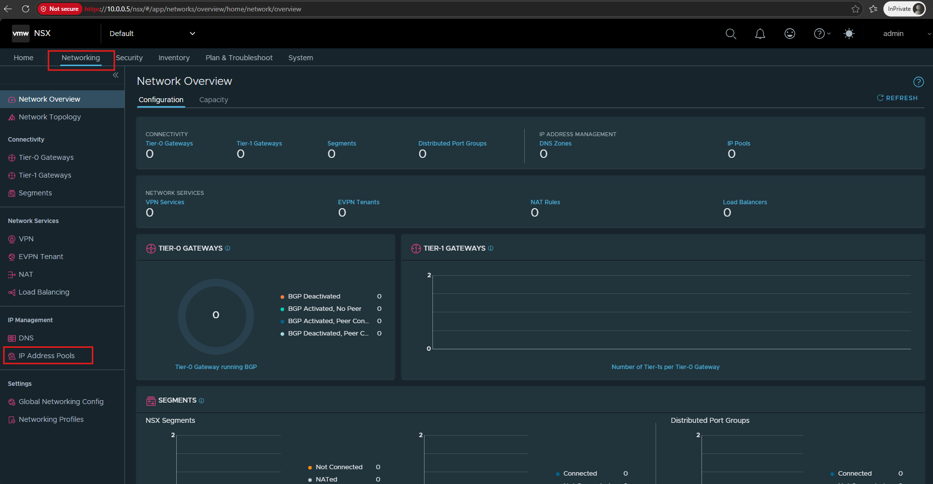
Click on Add IP Address Pool.
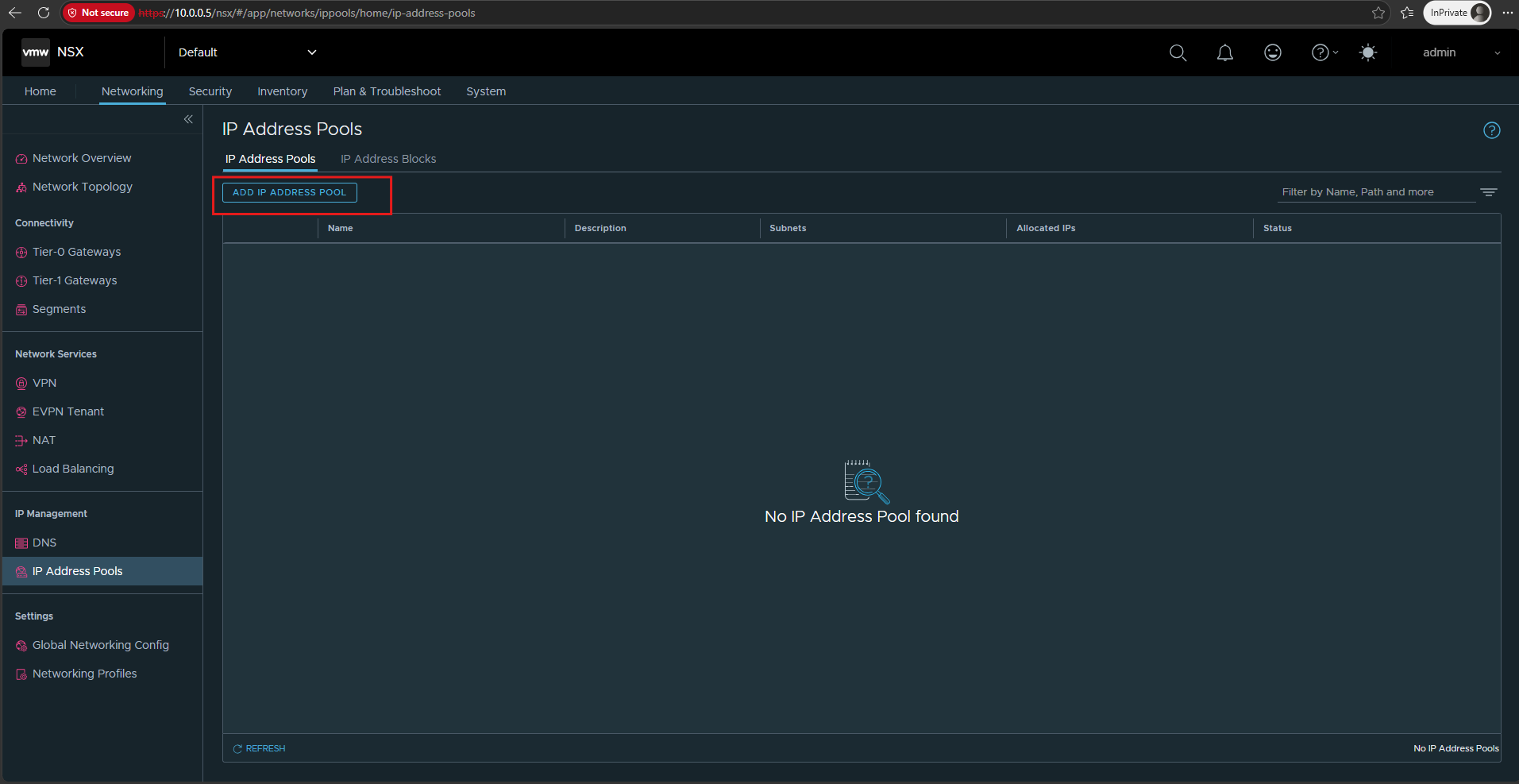
Provide a descriptive name for the pool. The actual TEP addresses are defined by adding a subnet to the pool using Set under Subnets.
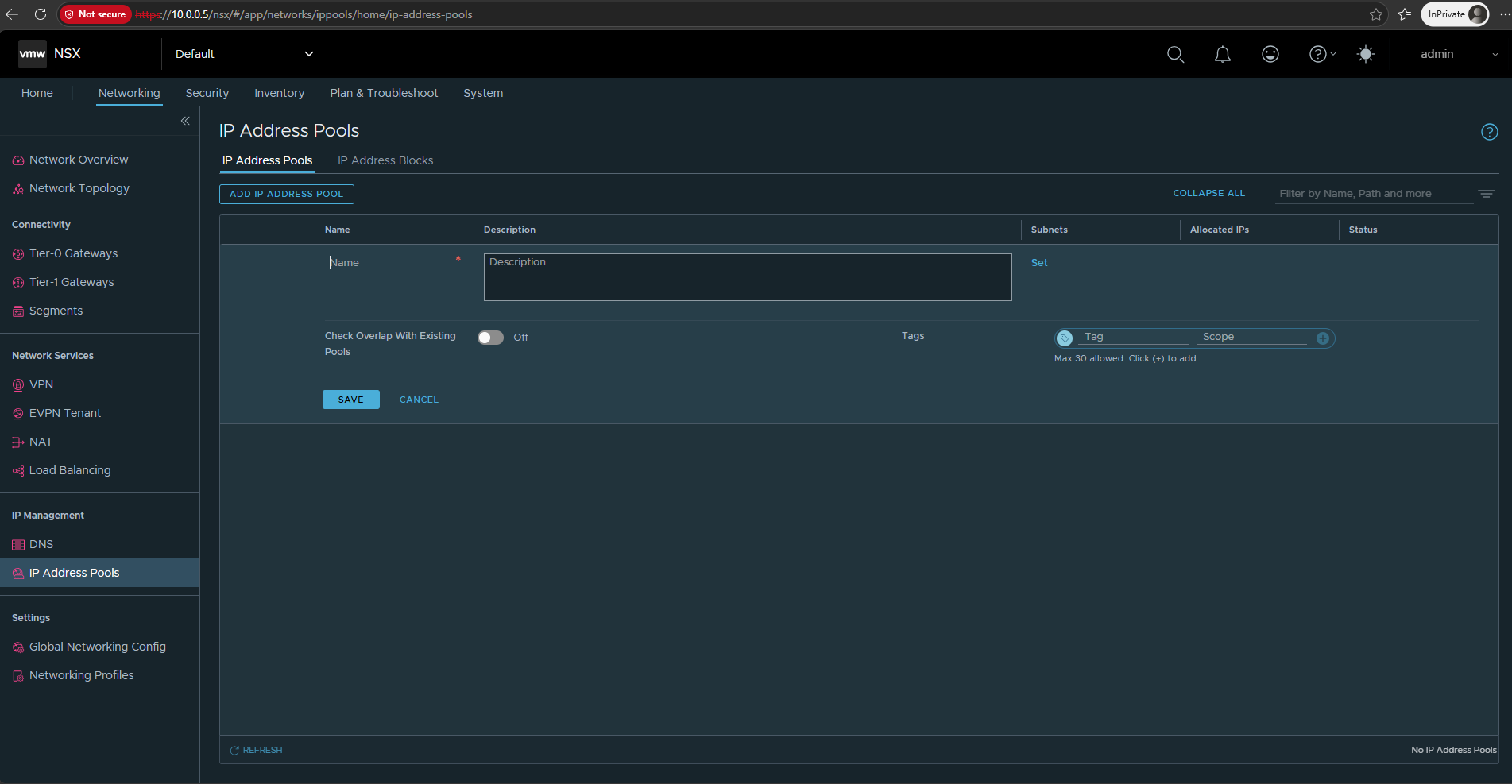
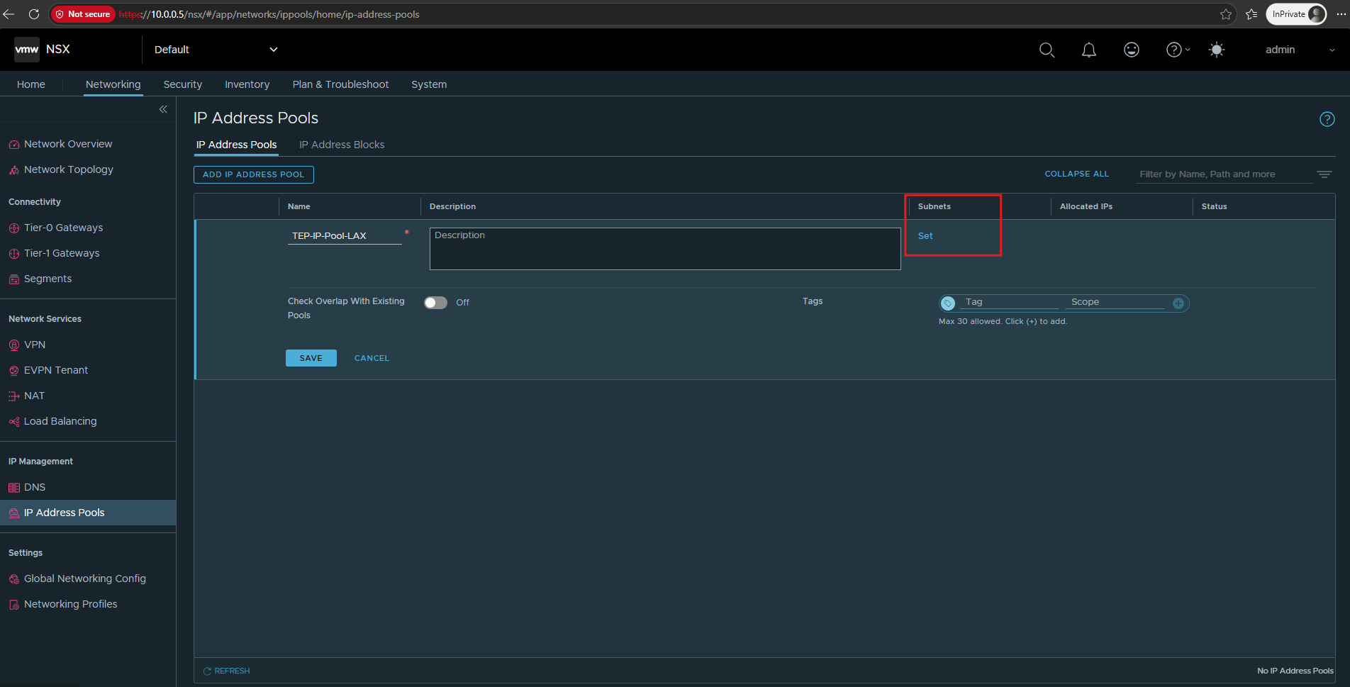
For my lab I will use for the name TEP-IP-Pool-LAX and click on Set under Subnets.
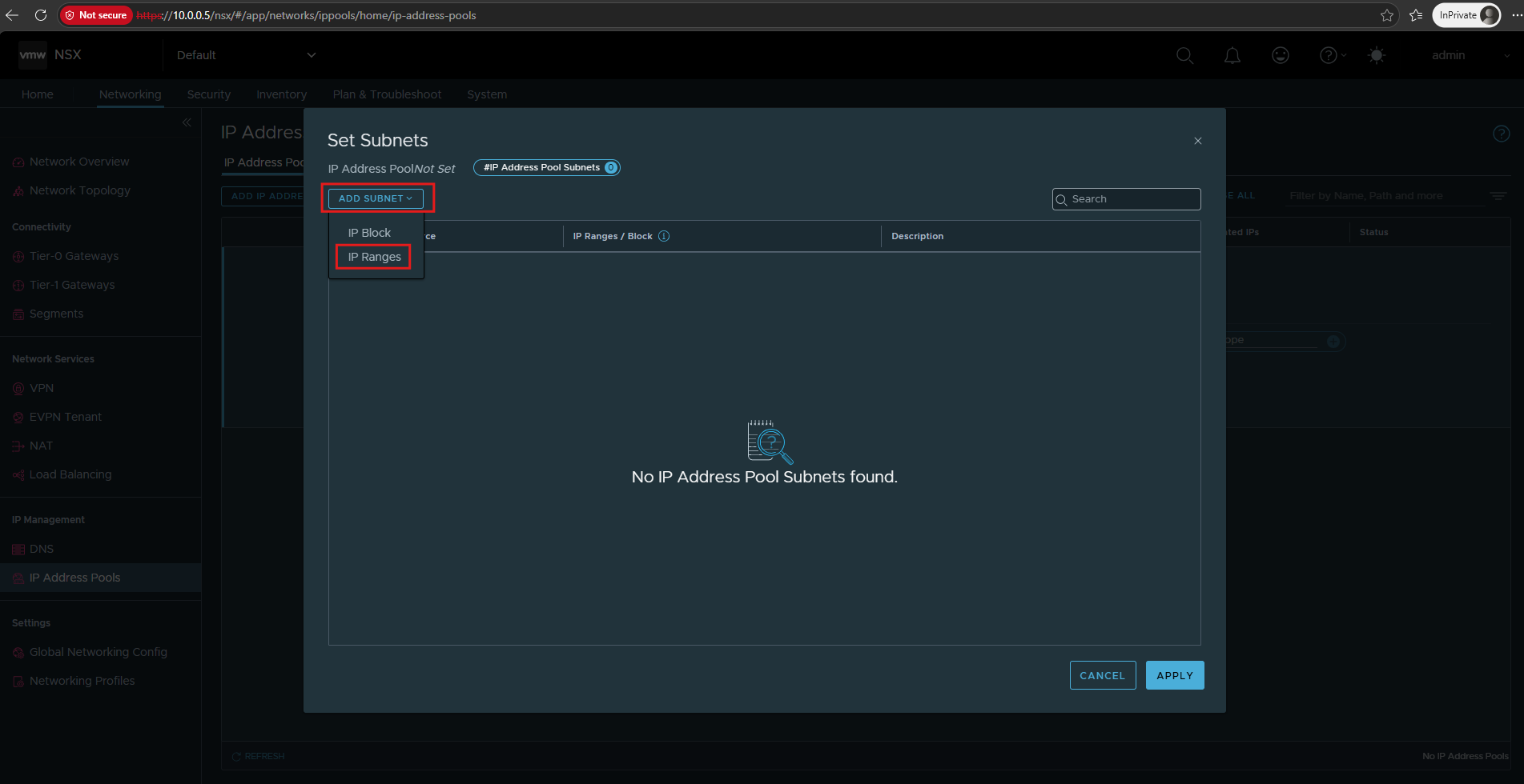
Select IP Ranges to manually define the subnet and address range used for the TEP interfaces.
An IP Block is not required for my lab, as I want to explicitly control the addresses allocated to the ESXi host TEPs.
We configure 10.0.50.0/24 as the dedicated TEP subnet with an allocation range of 10.0.50.10–10.0.50.20 and 10.0.50.1 as its gateway.
Since the subnet will be routed to our existing infrastructure networks, we can also use the existing DNS servers
10.0.0.70and10.0.0.75with the DNS suffixmatrixpost-lab.net.
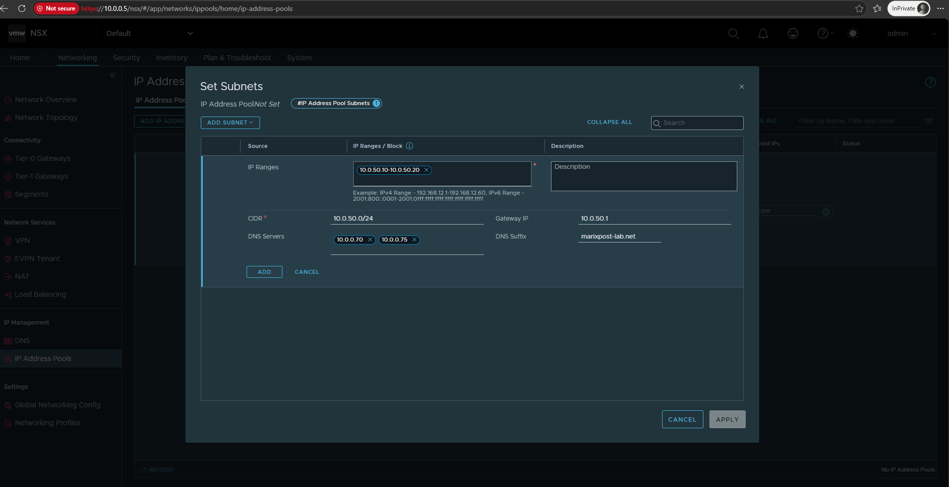
Once the subnet configuration is complete, click Add to add the subnet to the IP Address Pool and then Apply to return to the pool configuration.
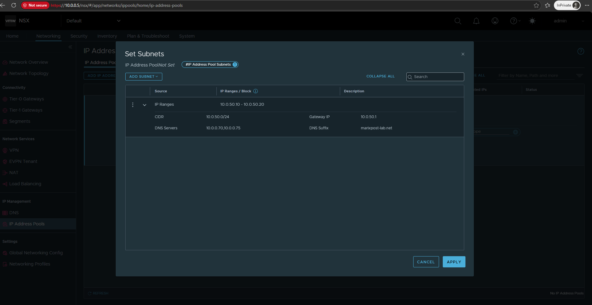
Click Save to create the IP Address Pool with the configured TEP subnet and allocation range.
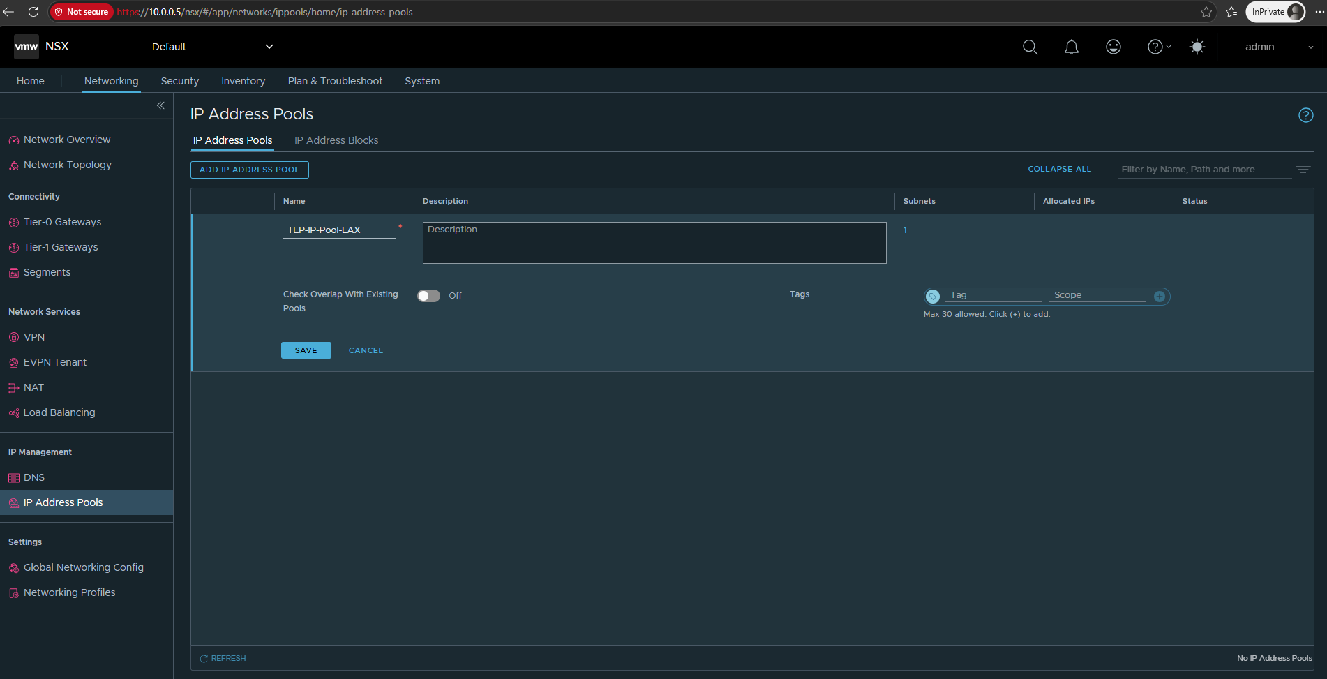
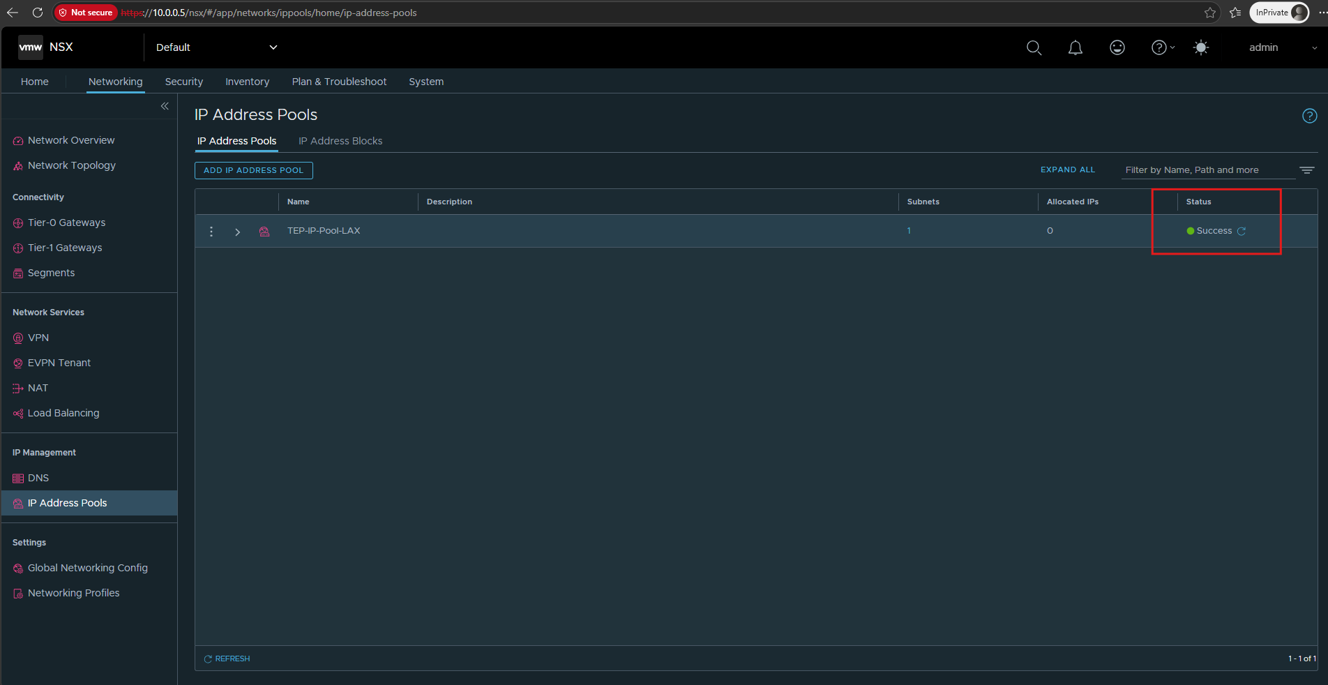
The TEP-IP-Pool-LAX IP Address Pool has now been created successfully.
At this point no addresses are allocated yet; NSX will assign TEP addresses from the pool once we prepare the ESXi hosts as transport nodes.
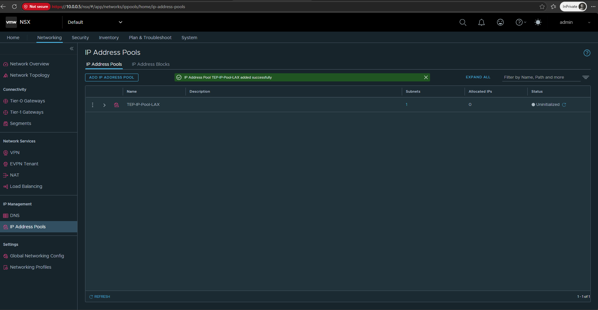
Once initialization has completed, the IP Address Pool TEP-IP-Pool-LAX shows a Success status.
Configure the Transport Zones
Next, we configure the Transport Zones, which define the scope in which NSX transport nodes can participate in overlay or VLAN-backed networks.
Go to System → Fabric → Transport Zones.
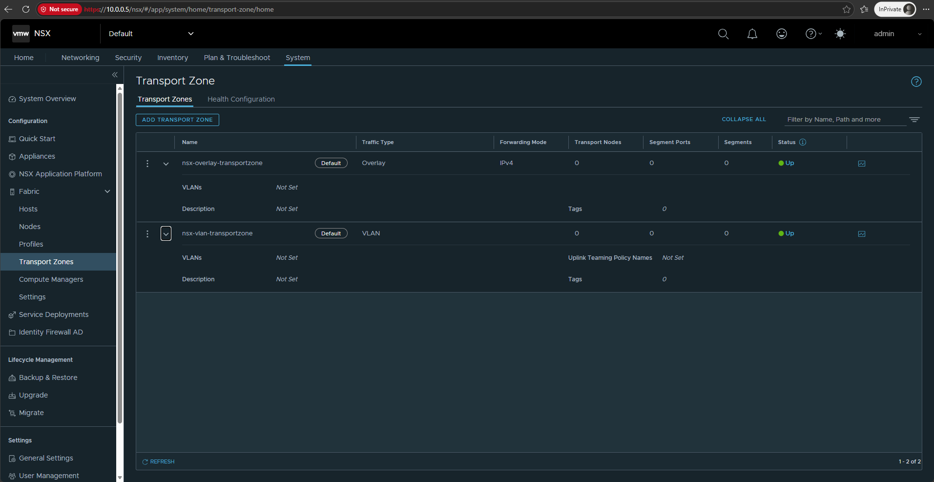
NSX provides two default transport zones: nsx-overlay-transportzone for encapsulated overlay traffic and nsx-vlan-transportzone for VLAN-backed connectivity.
The overlay transport zone uses GENEVE (Generic Network Virtualization Encapsulation) to carry logical network traffic between NSX transport nodes, whereas the VLAN transport zone connects NSX to traditional VLAN-based networks without overlay encapsulation.
Later, we will use the
nsx-vlan-transportzonefor the north-south uplink from the NSX Edge/Tier-0 Gateway toward our upstream router, in my lab, between the Tier-0 uplink and the external VLAN-based network. The Tier-0 uplink represents the NSX endpoint and will later connect to our upstream VRF-aware Ubuntu router.
Both transport zones are currently Up, but no transport nodes are assigned yet because the ESXi hosts have not been prepared.
Create an NSX Uplink Profile
The Uplink Profile defines how the NSX host switch connects the ESXi transport nodes to the physical network. It specifies settings such as the uplink teaming policy, active uplinks, transport VLAN, and MTU that will later be applied through the Transport Node Profile.
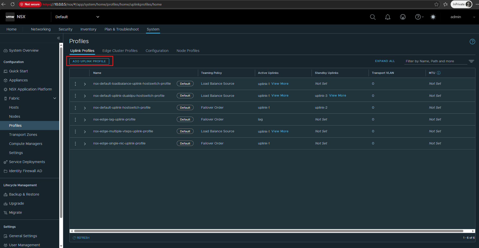
NSX already provides several predefined uplink profiles for common host and Edge configurations, including single-uplink, dual-uplink, load-balancing, and failover scenarios.
Instead of modifying these defaults, I will create a dedicated uplink profile for my lab environment.
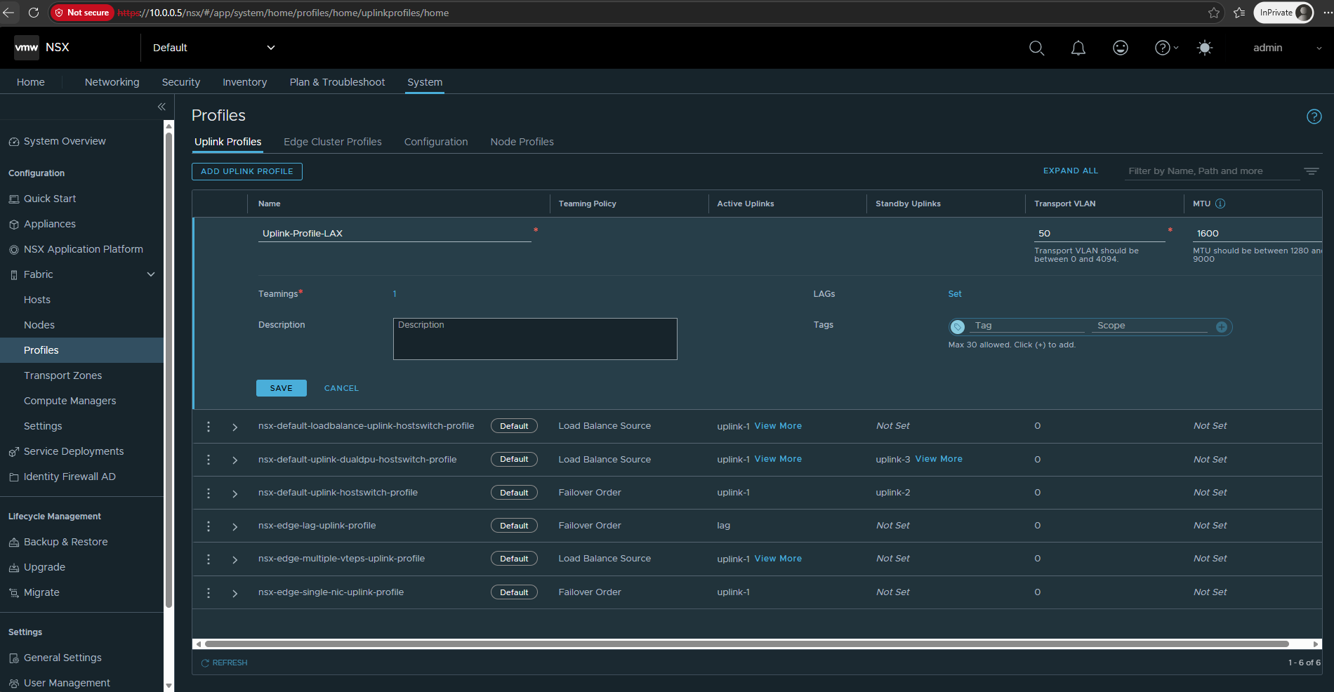
Go to System → Fabric → Profiles → Uplink Profiles. NSX provides several predefined uplink profiles, but for our ESXi transport nodes we will create a dedicated profile by clicking ADD UPLINK PROFILE.
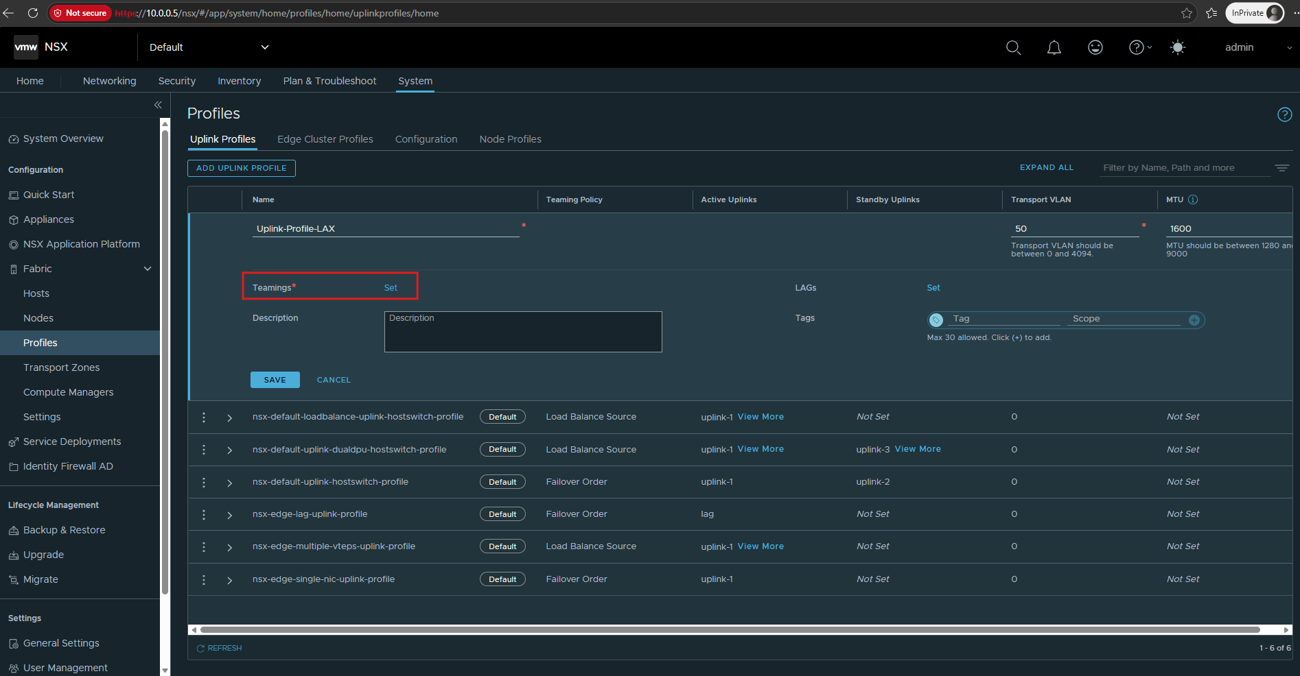
We define our own profile. For ymy lab I will use:
- Name:
Uplink-Profile-LAX - Transport VLAN:
50 - MTU: leave empty
- Teamings: click Set, this is the important bit where we define the uplink(s).
- LAGs: leave unset.
Click on Set under Teamings.
MTU: leave empty. Because we are using an existing vSphere Distributed Switch (VDS), NSX expects the MTU to be configured on the VDS rather than in the NSX Uplink Profile.
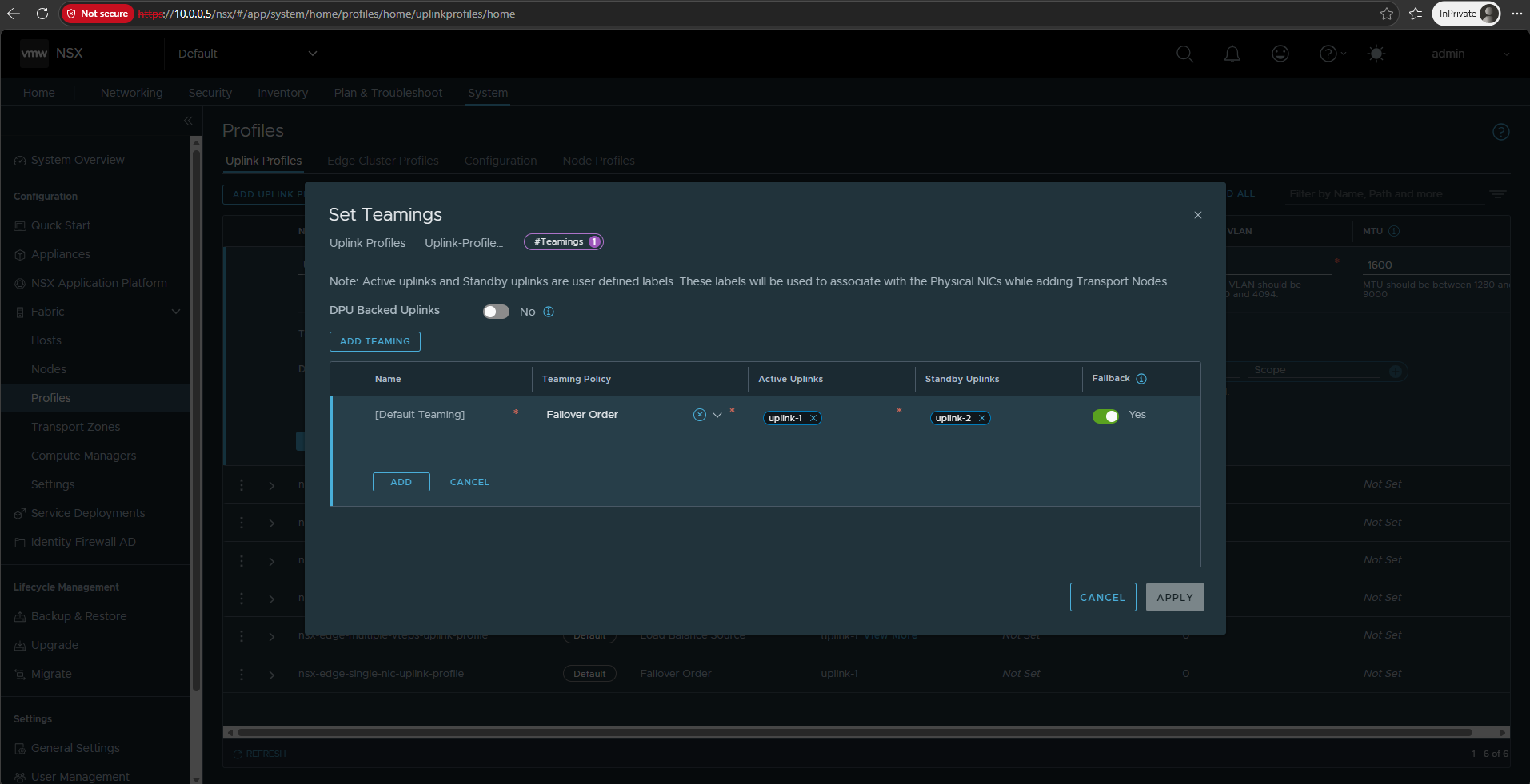
Configure the default teaming policy as Failover Order, using uplink-1 as the active and uplink-2 as the standby uplink. These logical NSX uplinks will later be mapped to the corresponding physical/vSphere uplinks when the ESXi hosts are prepared as transport nodes.
- Teaming Policy:
Failover Order - Active Uplinks:
uplink-1 - Standby Uplinks:
uplink-2 - Failback:
Yes - DPU Backed Uplinks:
No
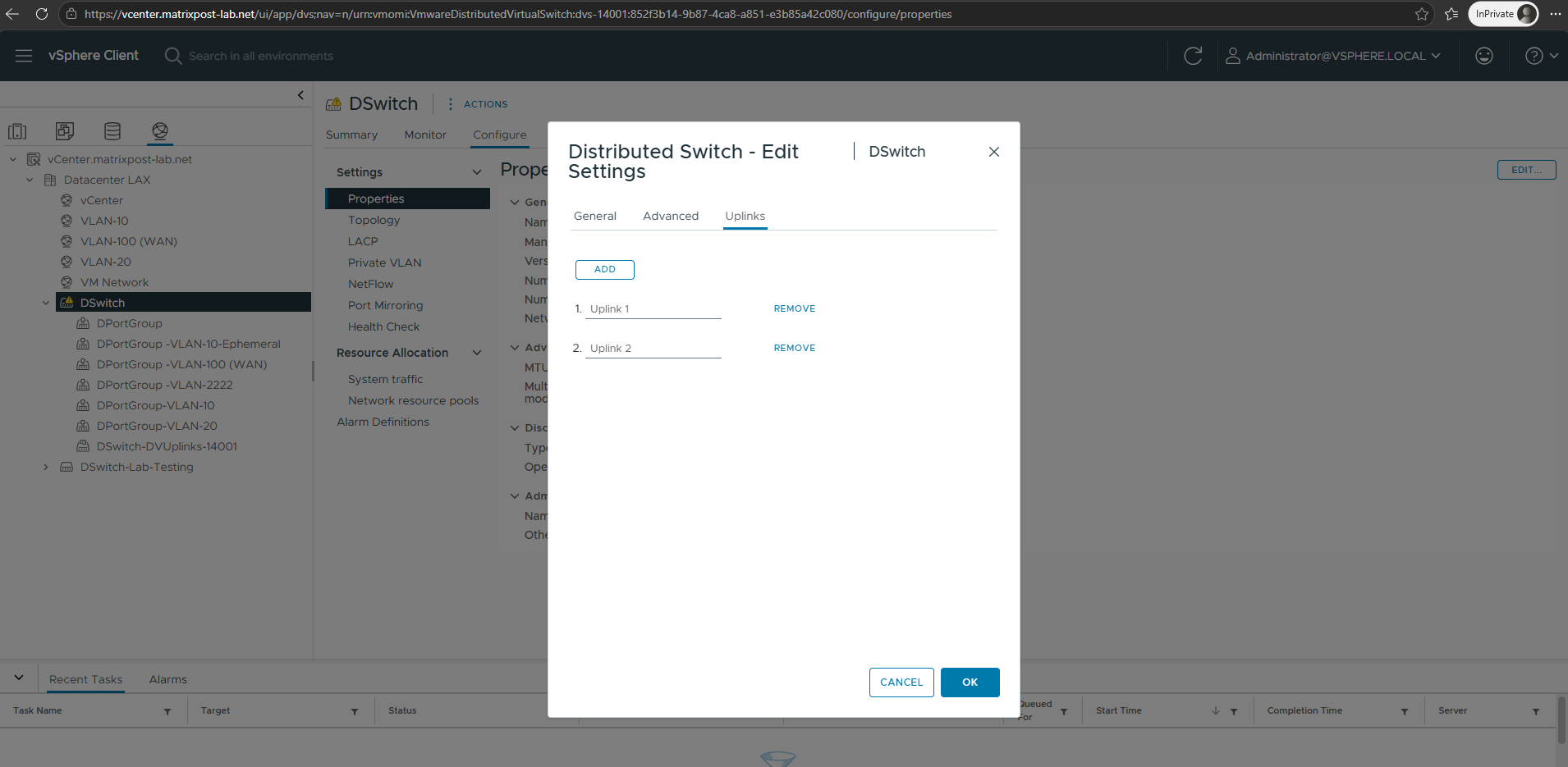
Before configuring the NSX teaming policy, we can verify the available uplinks on our vSphere Distributed Switch (VDS).
Our
DSwitchprovides two distributed uplinks,Uplink 1andUplink 2, which can later be mapped to the logical NSX uplinksuplink-1anduplink-2.Note: The existing VDS and its distributed port groups continue to operate normally and can coexist with NSX networking. This allows us to introduce NSX alongside our existing VLAN-backed networks without disrupting the current VM and management connectivity.
Configure the Default Teaming policy as Failover Order, with uplink-1 as the Active Uplink and uplink-2 as the Standby Uplink. With Failback enabled, traffic automatically returns to uplink-1 when the primary uplink becomes available again.
Then ADD → APPLY.
Click on SAVE.
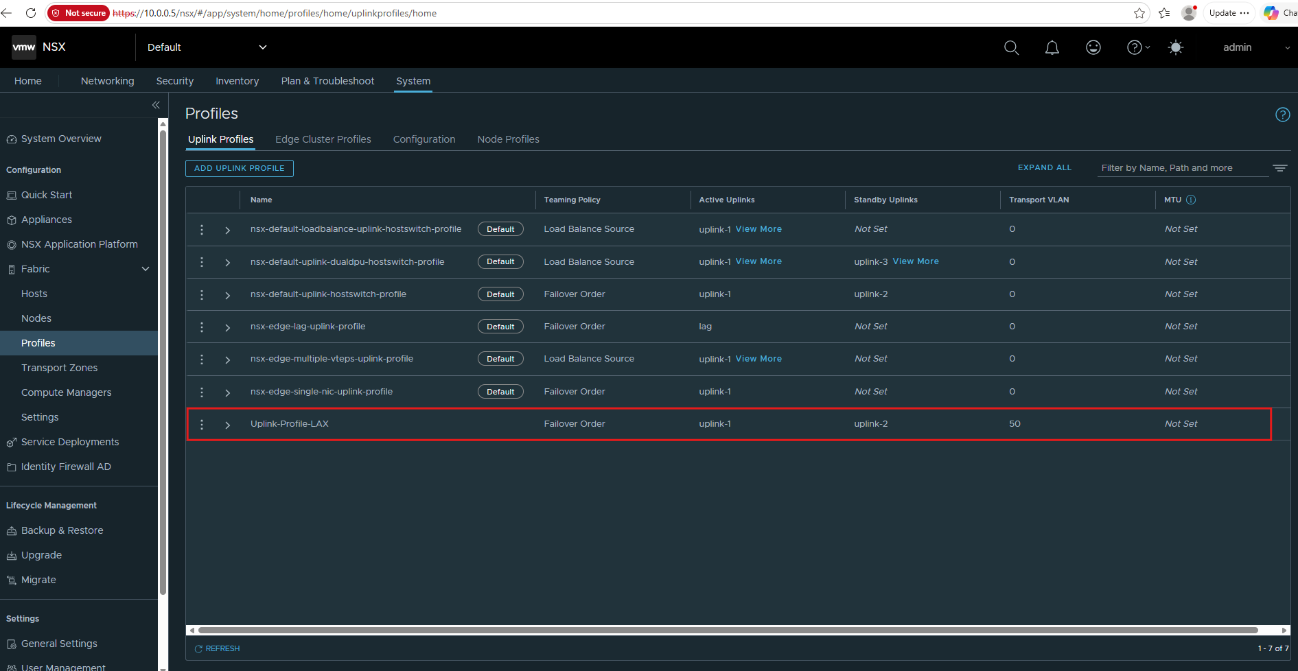
The new Uplink-Profile-LAX is now available with Failover Order, uplink-1 as active and uplink-2 as standby, using VLAN 50 for TEP traffic and an MTU of 1600.
This profile will be used when preparing the ESXi hosts as NSX transport nodes.
Create a Transport Node Profile
Next, we create a Transport Node Profile that defines how the ESXi hosts in our cluster will be prepared for NSX. The profile combines the required transport zones, uplink configuration, TEP IP assignment, and vSphere Distributed Switch settings.
We add both the Overlay and VLAN Transport Zones to the Transport Node Profile. The Overlay Transport Zone enables the ESXi transport nodes to participate in the GENEVE-based overlay networks carrying our tenant workload traffic.
The VLAN Transport Zone enables the same transport nodes and their NSX-prepared VDS to participate in NSX-managed VLAN-backed segments, which we will later use to provide the Edge datapath/TEP connectivity and north-south connectivity toward the upstream network.
In Part 2, this VLAN-backed connectivity will ultimately provide the path from the NSX Tier-0 uplink toward our VRF-aware Ubuntu upstream router.
Navigate to System → Fabric → Hosts → Transport Node Profile and click Add Transport Node Profile.
The transport node profile defines the NSX networking configuration that will later be applied consistently to all ESXi hosts in the cluster.
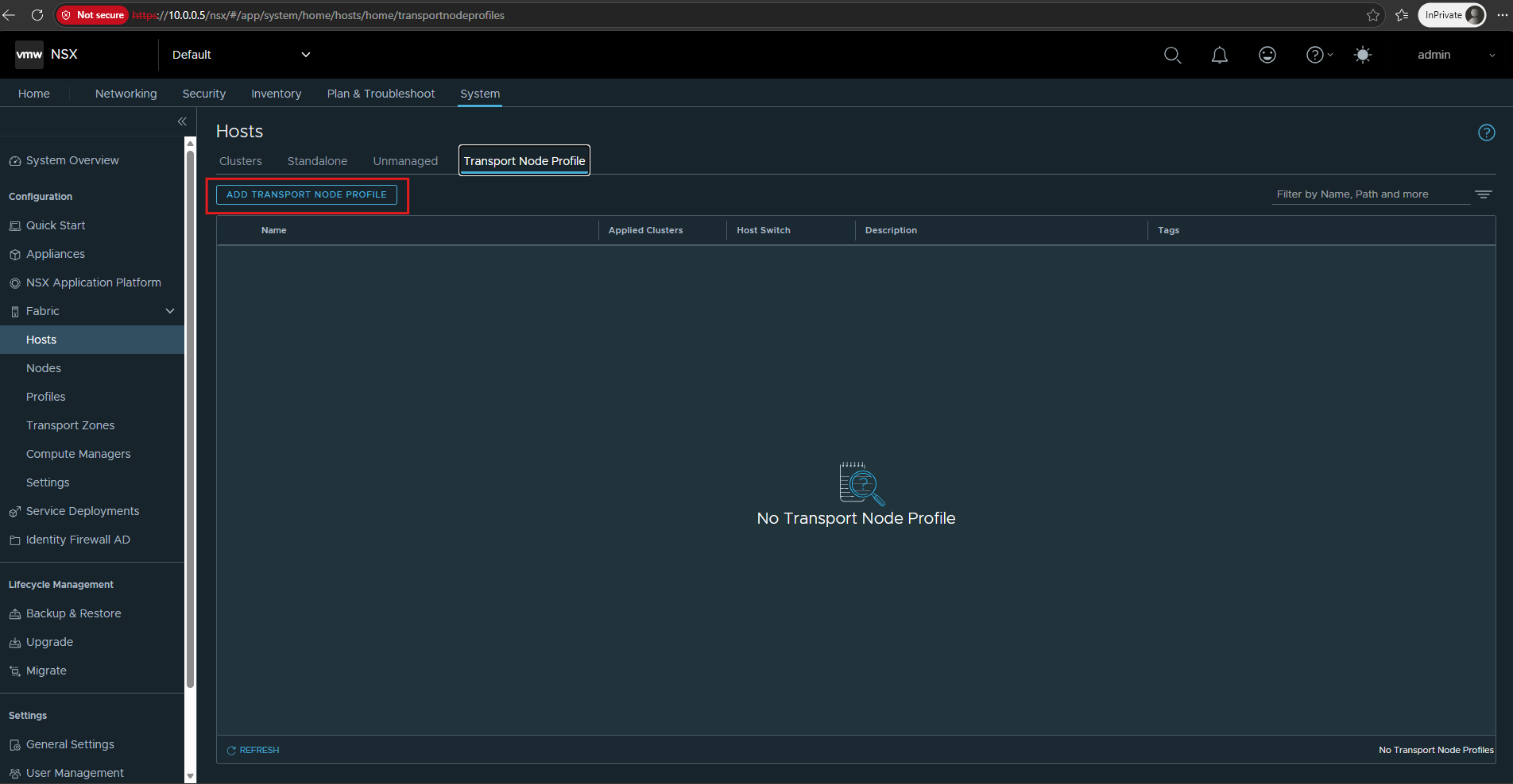
We give it a consistent name, for example: Transport-Node-Profile-LAX
Then click Set under Host Switch.
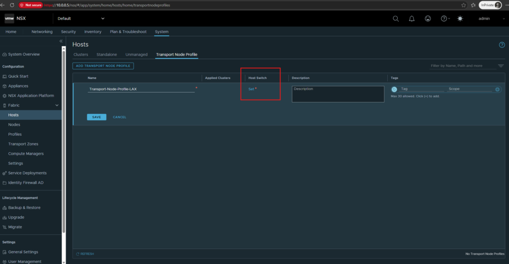
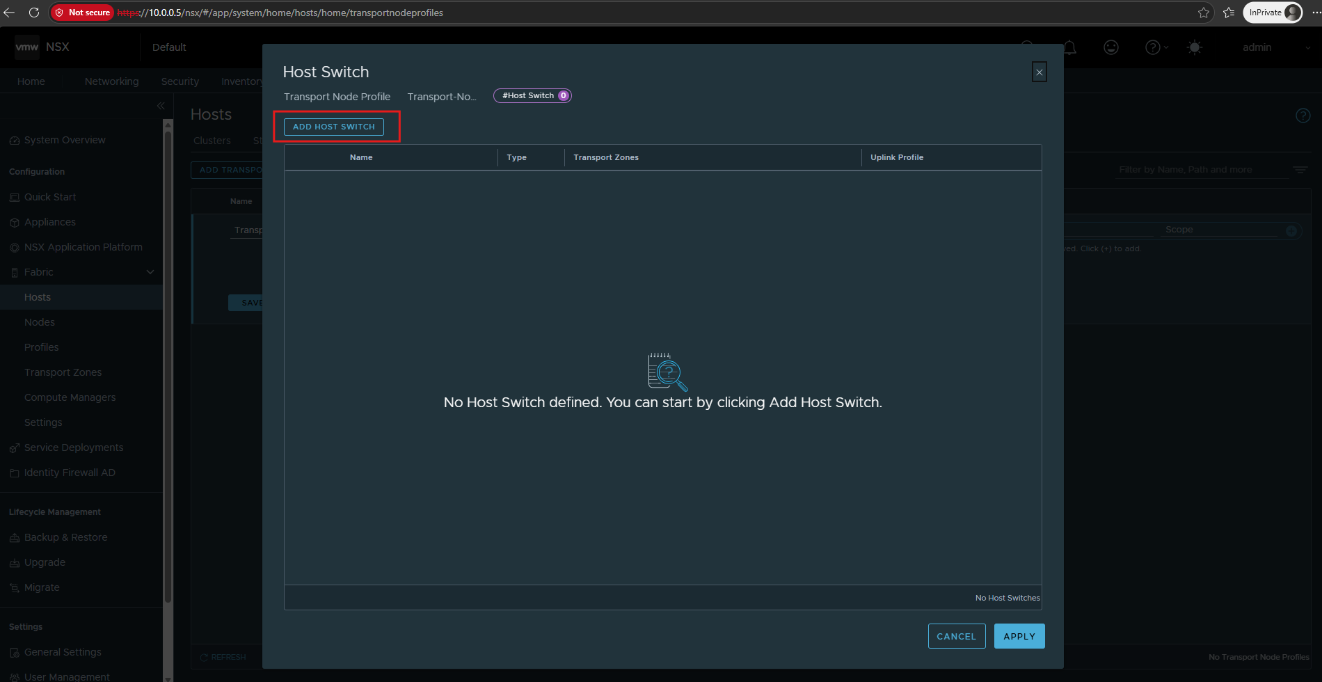
Click Add Host Switch to define the switch configuration that will be applied to the ESXi transport nodes.
We will use our existing vSphere Distributed Switch (VDS) rather than creating a separate NSX Virtual Distributed Switch.
Select:
- vCenter: our previously registered vCenter in NSX (in my case
Matrix-vCenter) - VDS: our distributed vSwitch (in my case
DSwitch) - Transport Zones: select both
nsx-overlay-transportzoneandnsx-vlan-transportzone - Uplink Profile: the uplink profile we created previously (in my case
Uplink-Profile-LAX) - IP Address Type (TEP):
IPv4 - IPv4 Assignment: Use IP Pool →
TEP-IP-Pool-LAX(the IP Pool we created previously)
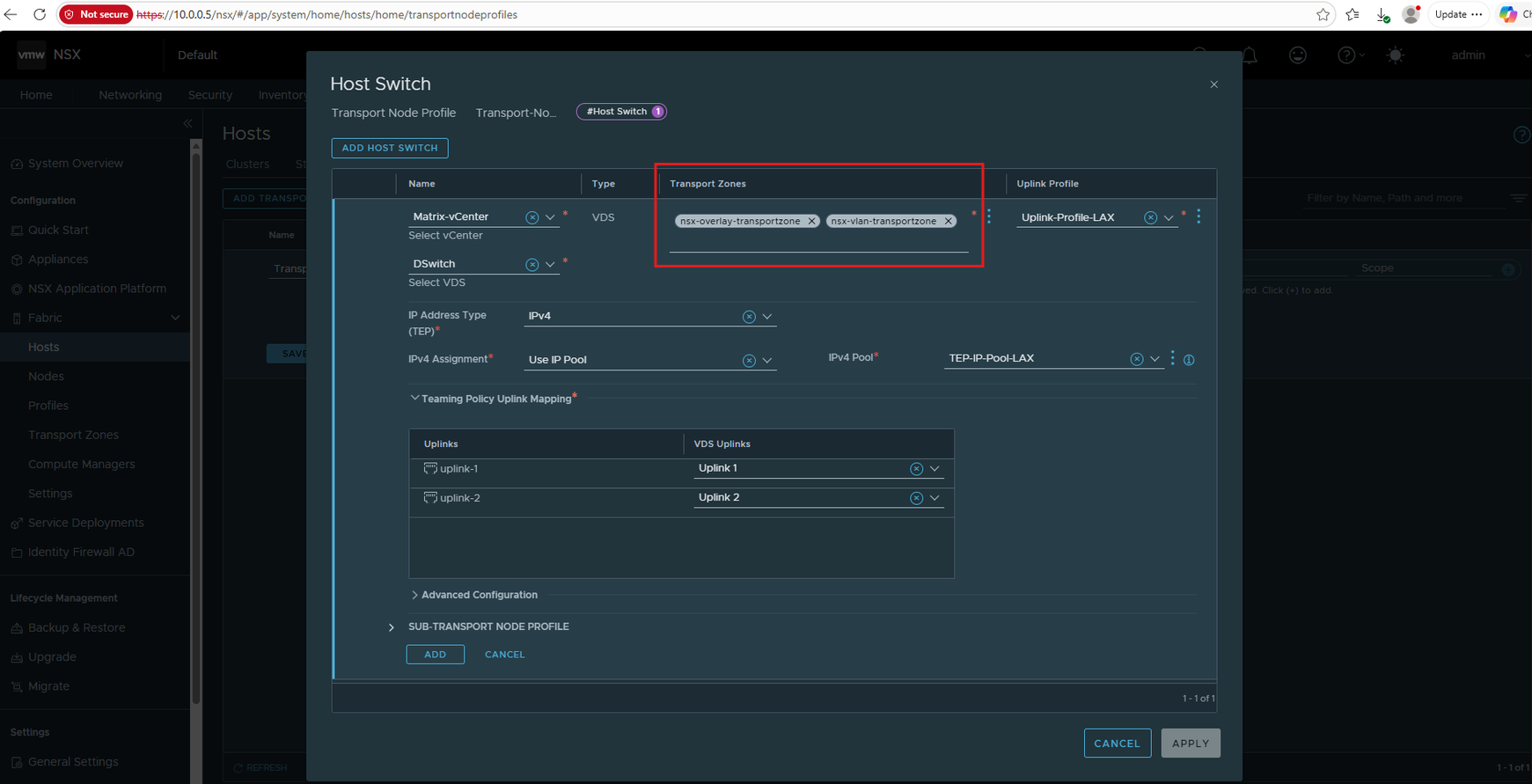
Next we map the logical NSX uplinks from our Uplink-Profile-LAX to the corresponding uplinks of the existing vSphere Distributed Switch: uplink-1 → Uplink 1 and uplink-2 → Uplink 2.
Once the logical NSX uplinks are mapped to the corresponding VDS uplinks, click ADD to add the host switch configuration to the Transport Node Profile.
This mapping determines which VDS uplinks NSX uses for the active and standby paths defined by our teaming policy.
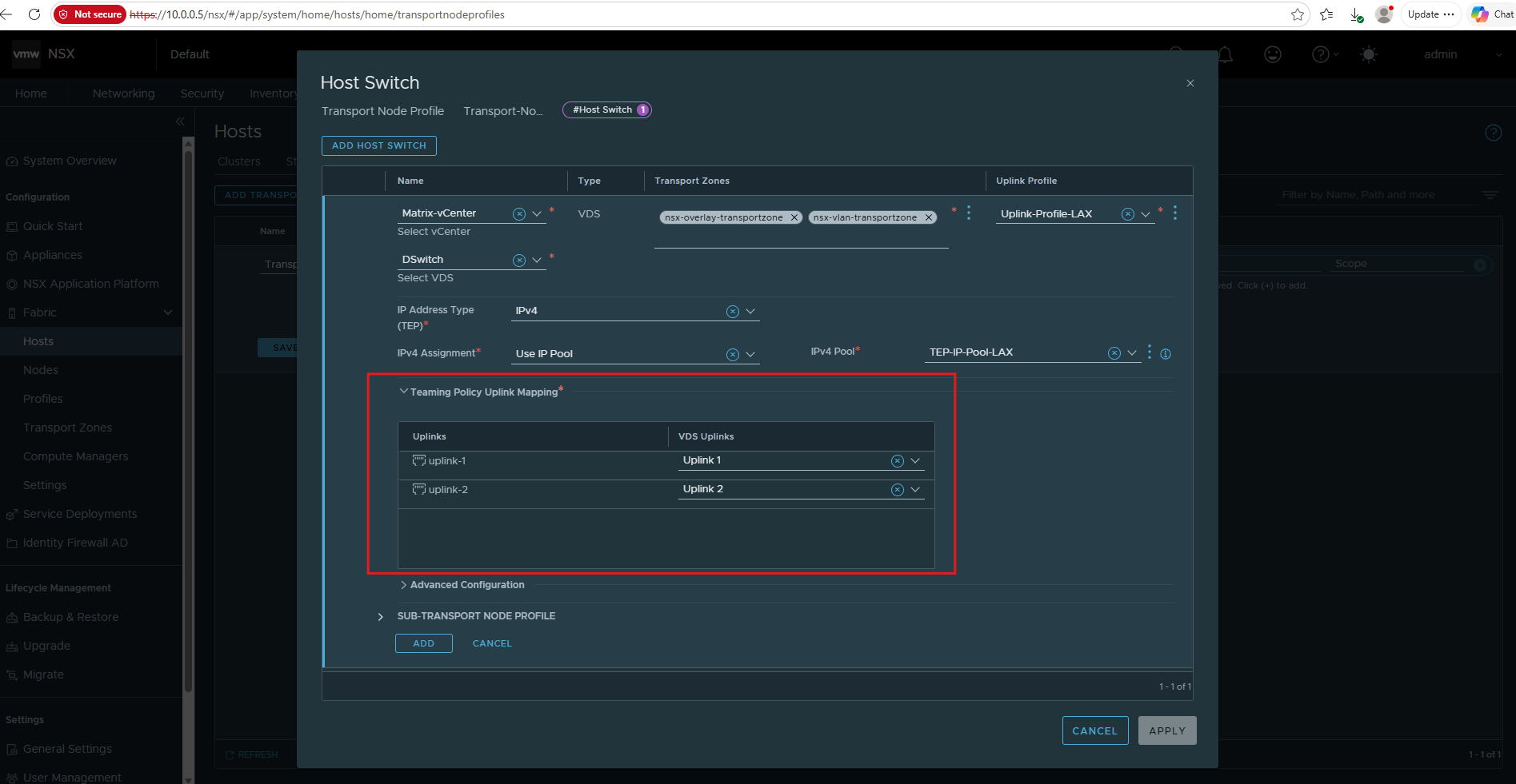
Review the completed host switch configuration, including the VDS, overlay transport zone, TEP IP pool, uplink profile, and uplink mappings.
Click APPLY to return the configuration to the Transport Node Profile.
Back in the Transport Node Profile configuration, enter a descriptive name such as Transport-Node-Profile-LAX. The profile now contains the configured host switch; click SAVE to create the Transport Node Profile.
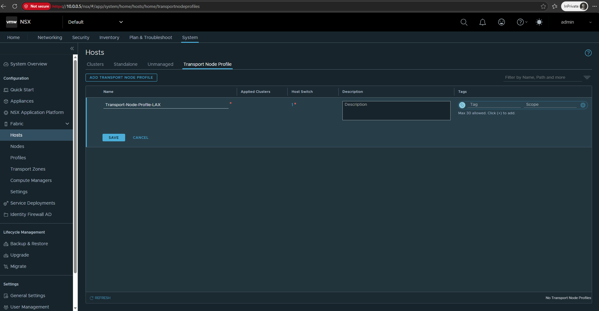
If we nevertheless specify an MTU value in the Uplink Profile previously, NSX rejects the Transport Node Profile configuration and explicitly requires the MTU field to be left empty when using a VDS.
“VDS [DSwitch] does not need field MTU to be specified in its uplink profile … Keep the field MTU in uplink profile for a VDS switch empty.”
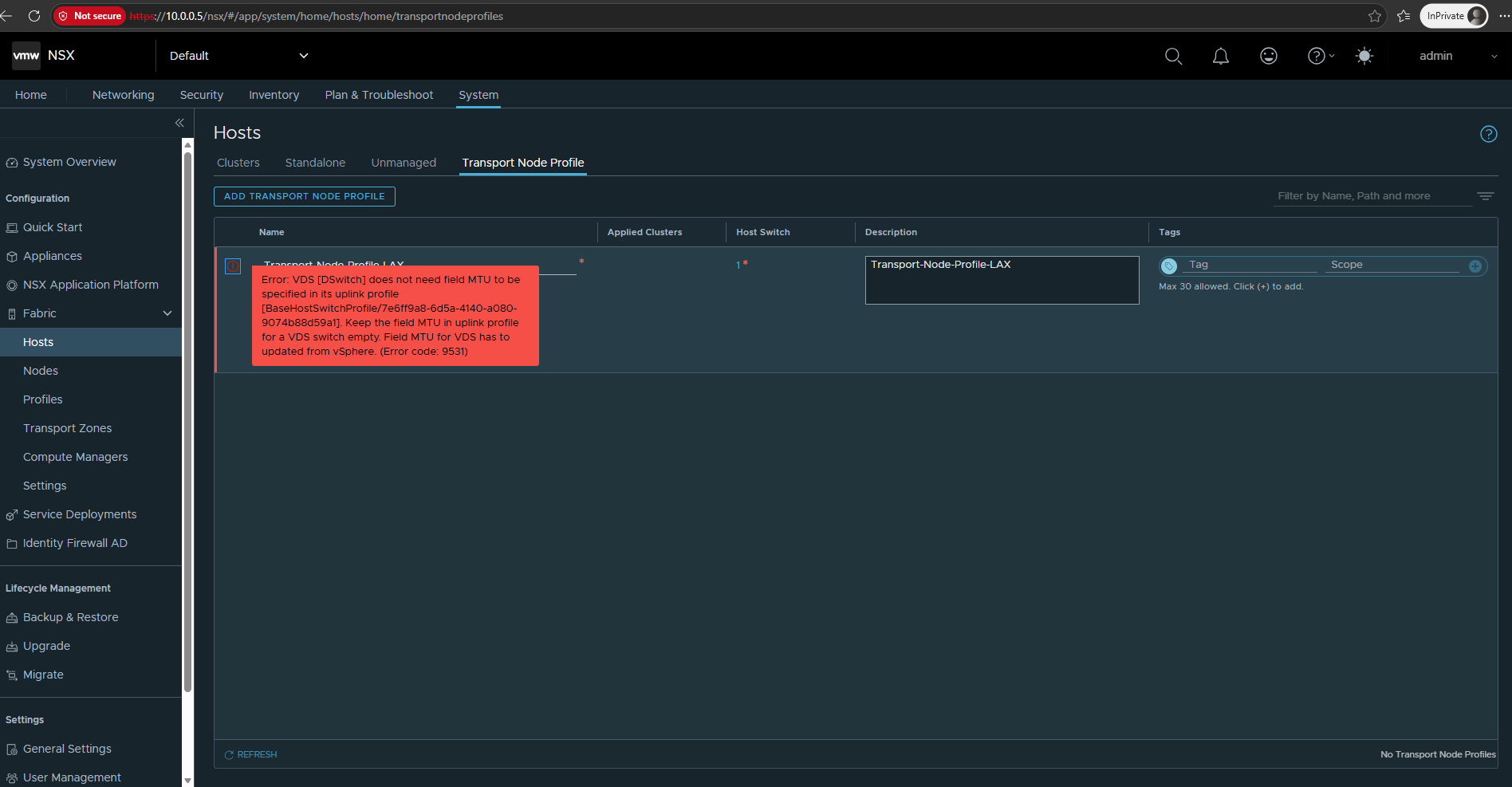
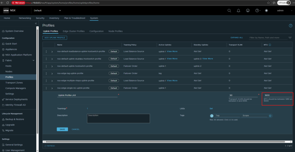
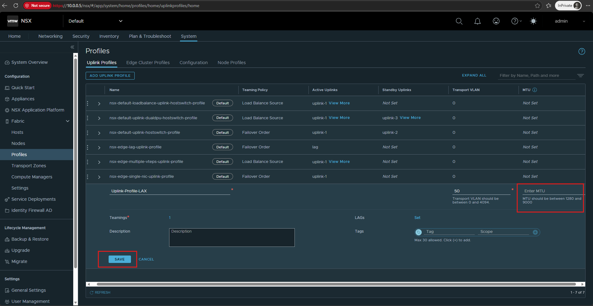
So in my case I now need to edit the Uplink-Profile-LAX and remove the 1600 MTU value completely, leaving the MTU field empty. The MTU for this setup is inherited/controlled by the existing VDS instead.
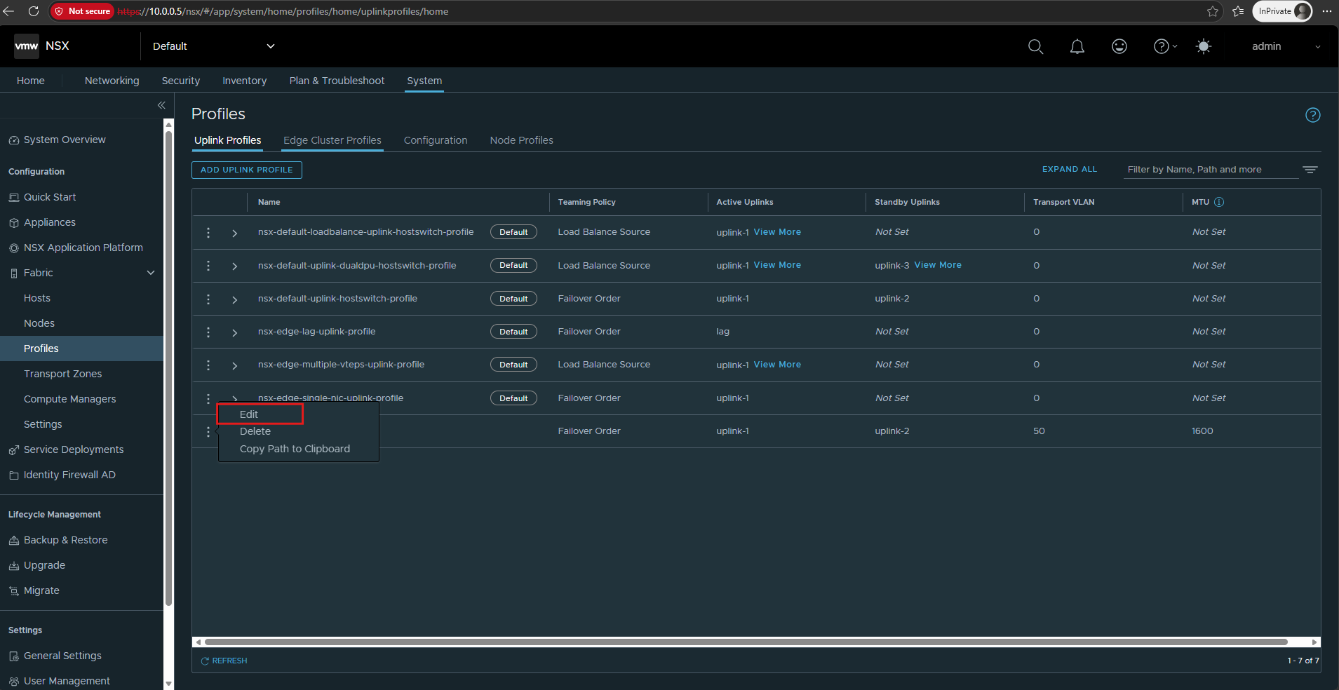
Navigate to System → Fabric → Profiles and click on the three dots for our previously created uplink profile to edit.
Unfortunately, navigating away to modify the Uplink Profile causes the unsaved Transport Node Profile configuration to be lost, so we need to configure it again.
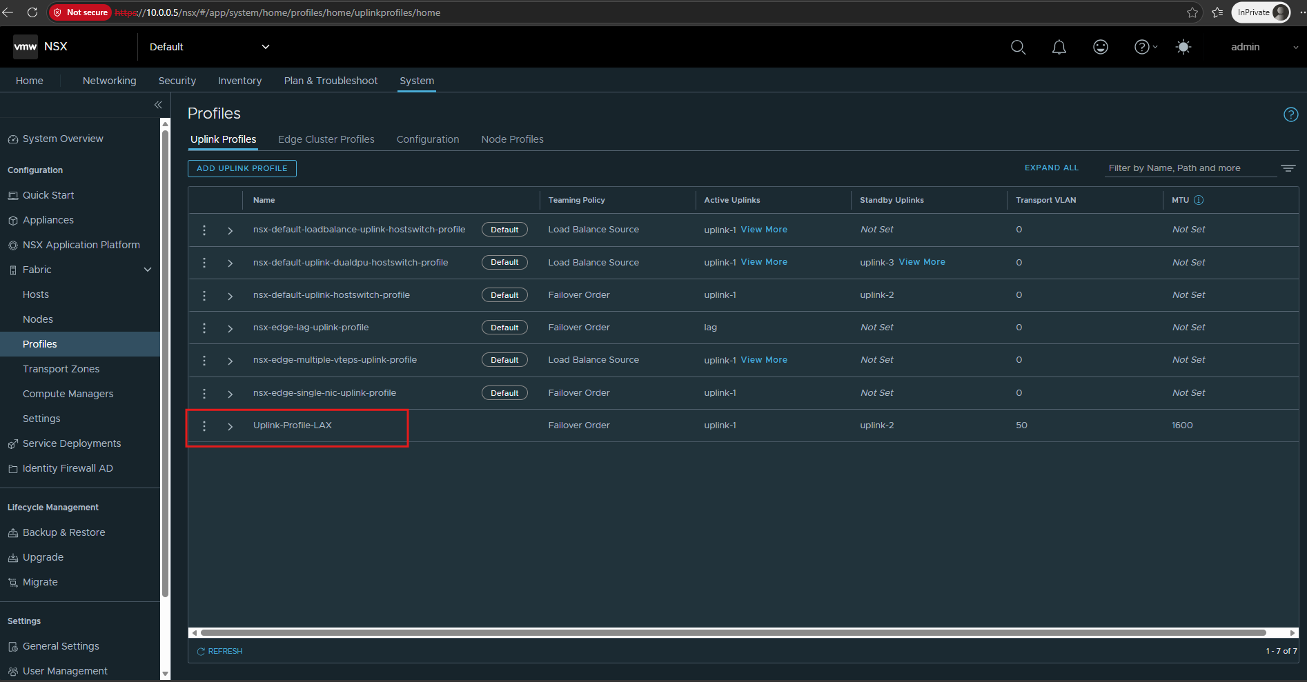
Select Edit.
Remove the MTU.
Click on SAVE.
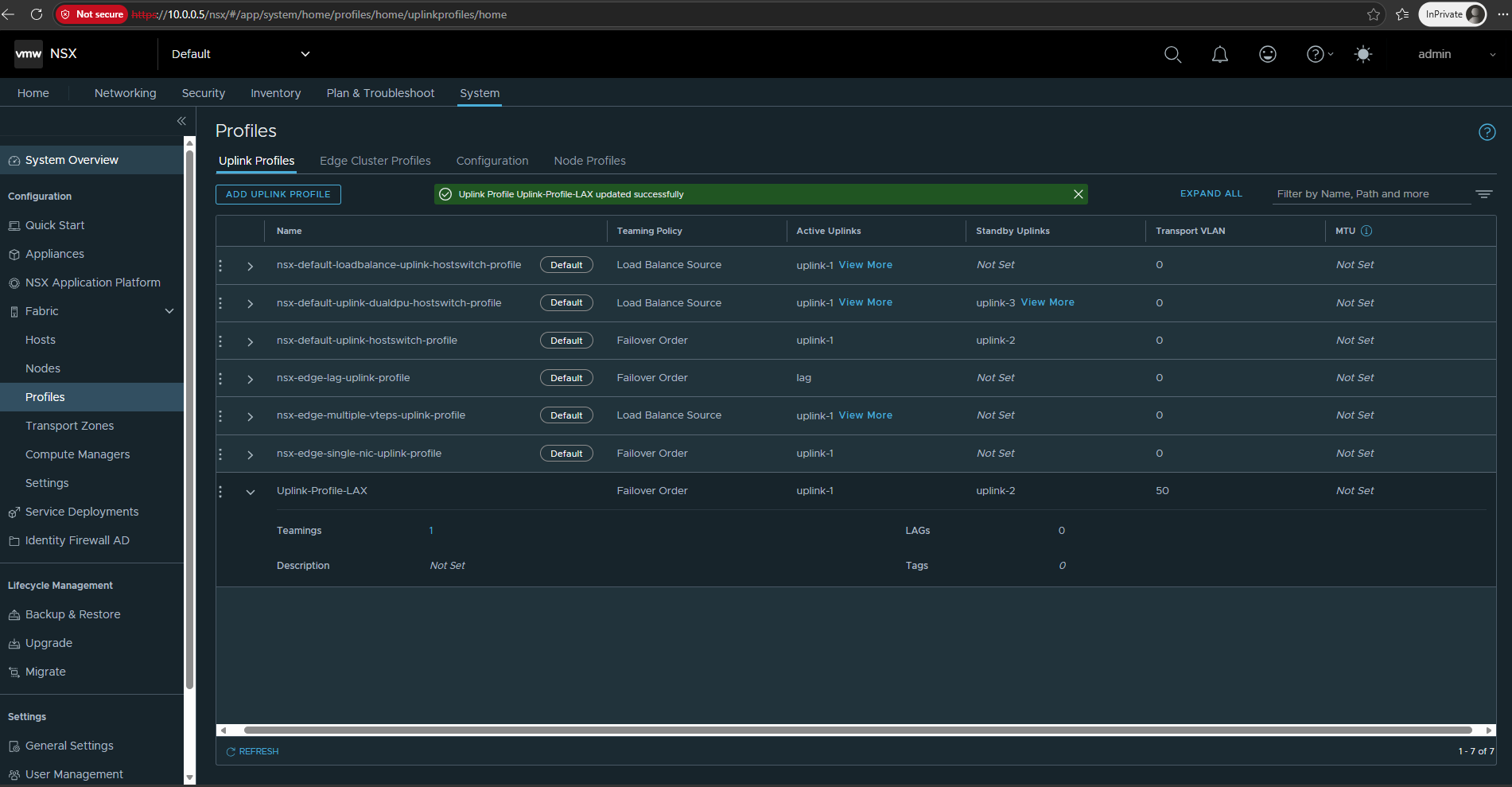
After removing the MTU value from Uplink-Profile-LAX and recreating the Transport Node Profile, Transport-Node-Profile-LAX can now be saved successfully.
The profile is ready to be applied to our ESXi cluster.
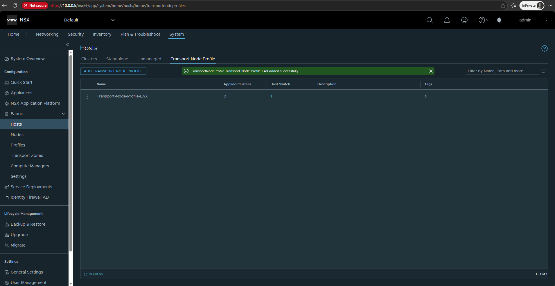
Prepare the ESXi Hosts
With the required NSX transport network components configured, we can now prepare the ESXi hosts as NSX Transport Nodes. We will apply the previously created Transport-Node-Profile-LAX to HA-Cluster-LAX, allowing NSX to install and configure the required components on both ESXi hosts.
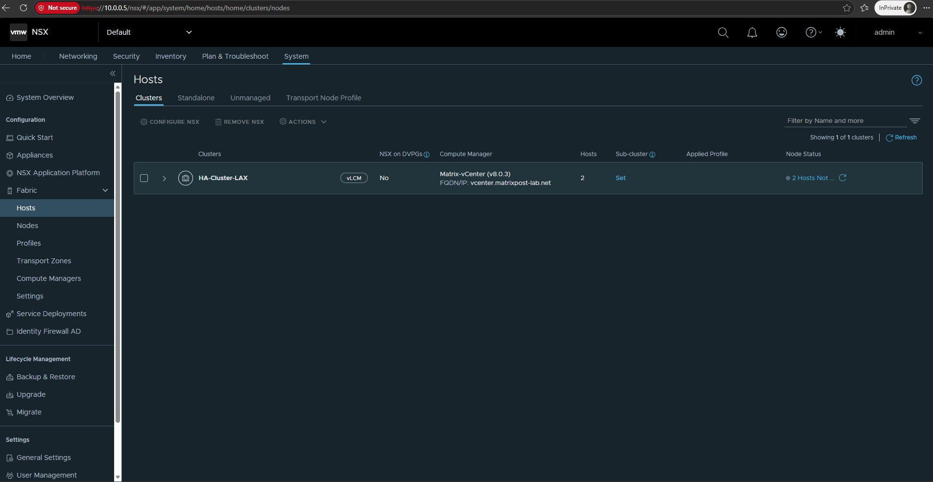
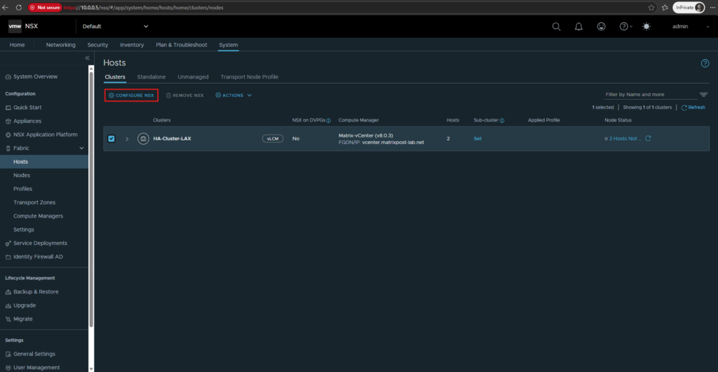
Select HA-Cluster-LAX and click Configure NSX.
We can now apply our previously created Transport-Node-Profile-LAX to the cluster, which will trigger the preparation of both ESXi hosts as NSX Transport Nodes.
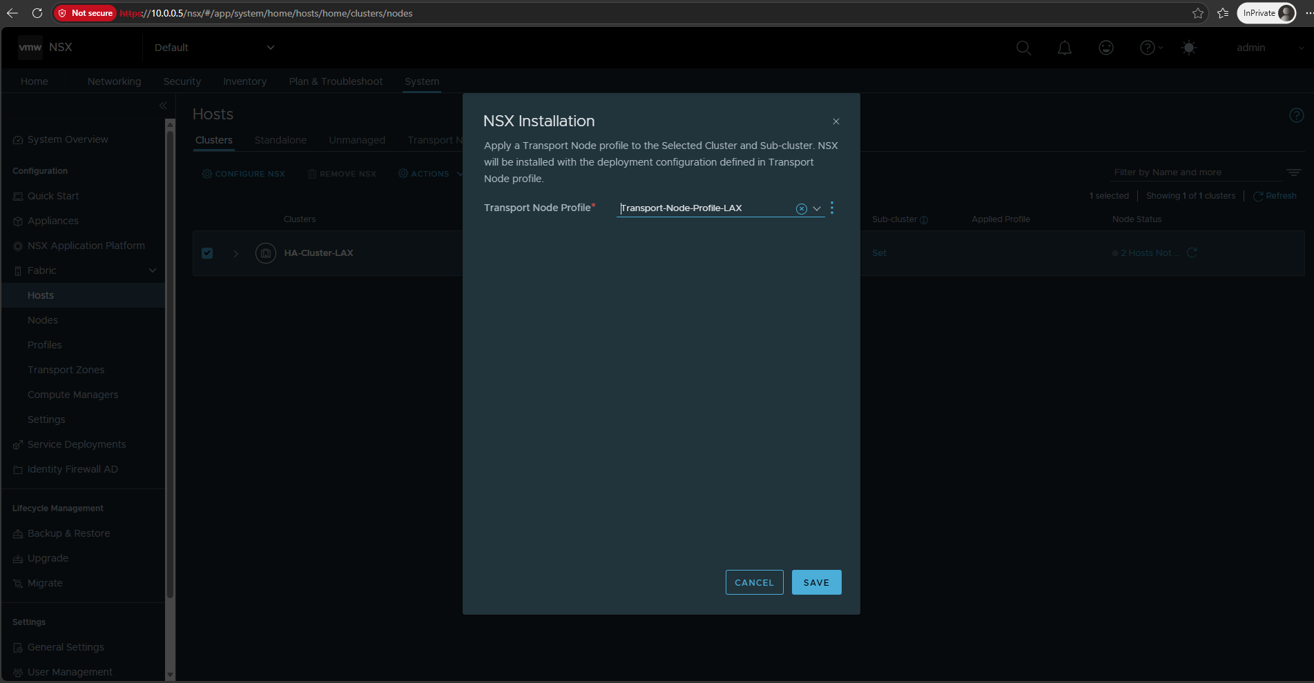
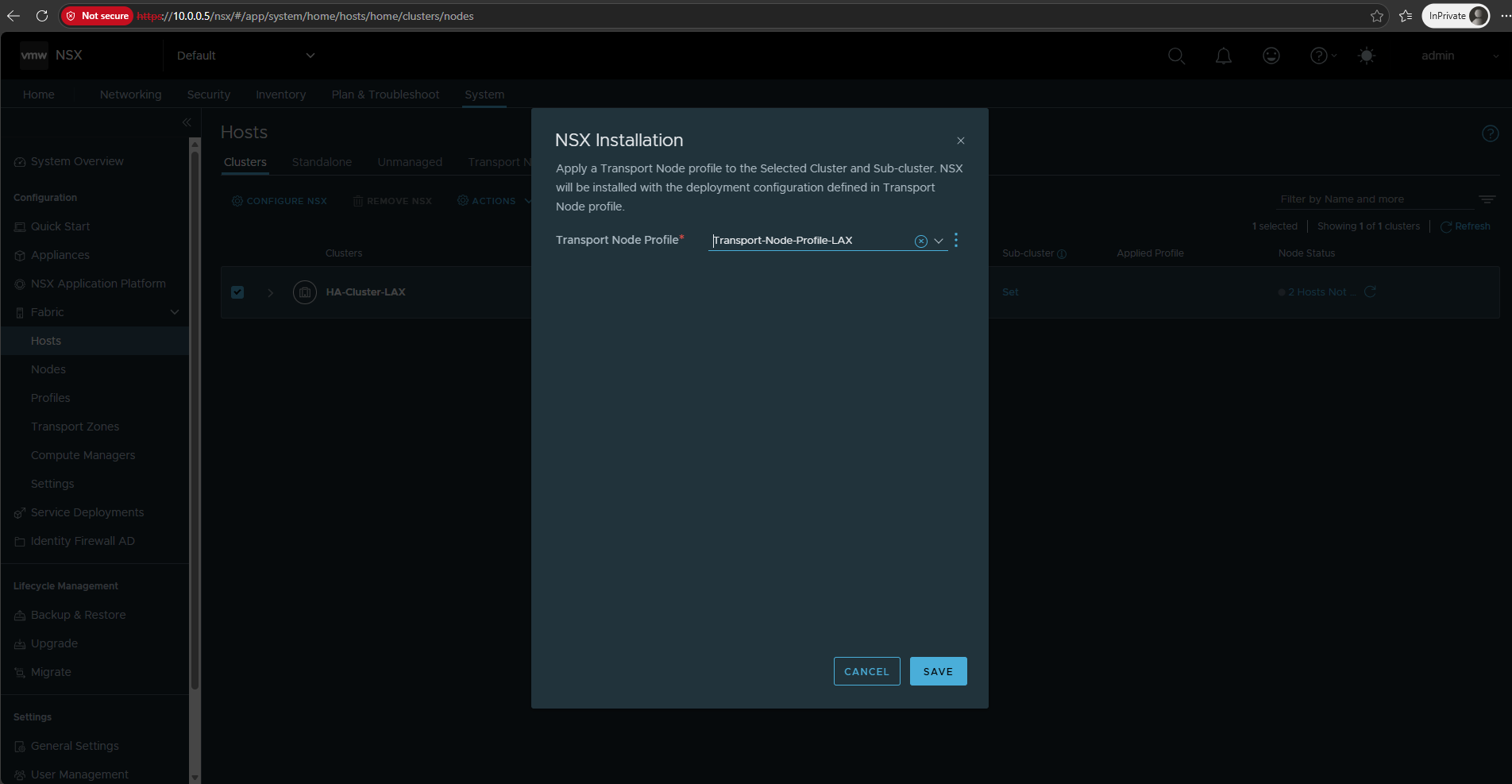
In the NSX Installation dialog, select our previously created Transport-Node-Profile-LAX and click Save.
NSX will then apply the configuration defined in the profile to all ESXi hosts in HA-Cluster-LAX and begin their preparation as NSX Transport Nodes.
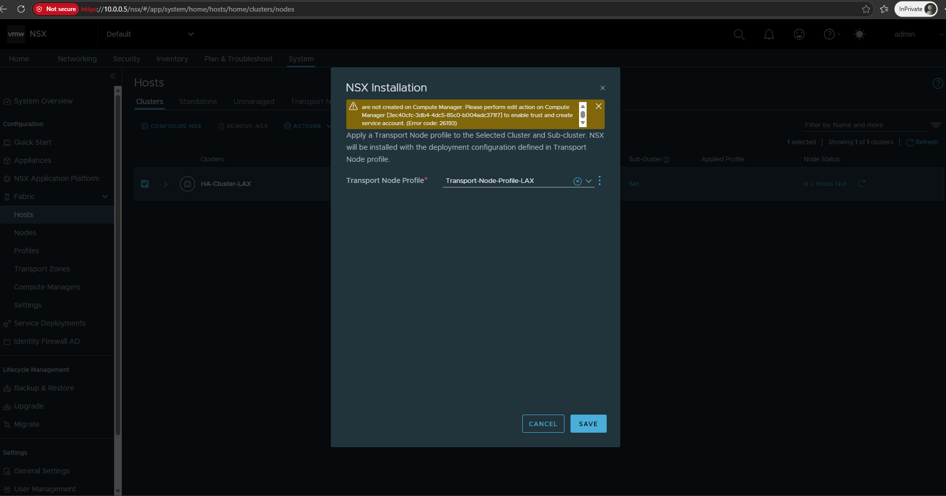
Because HA-Cluster-LAX is managed by vSphere Lifecycle Manager (vLCM), NSX requires a trusted integration with the vCenter Server before the cluster can be prepared. If Trust was not enabled when the vCenter Server was added as a Compute Manager, the NSX installation fails at this point with Error 26192.
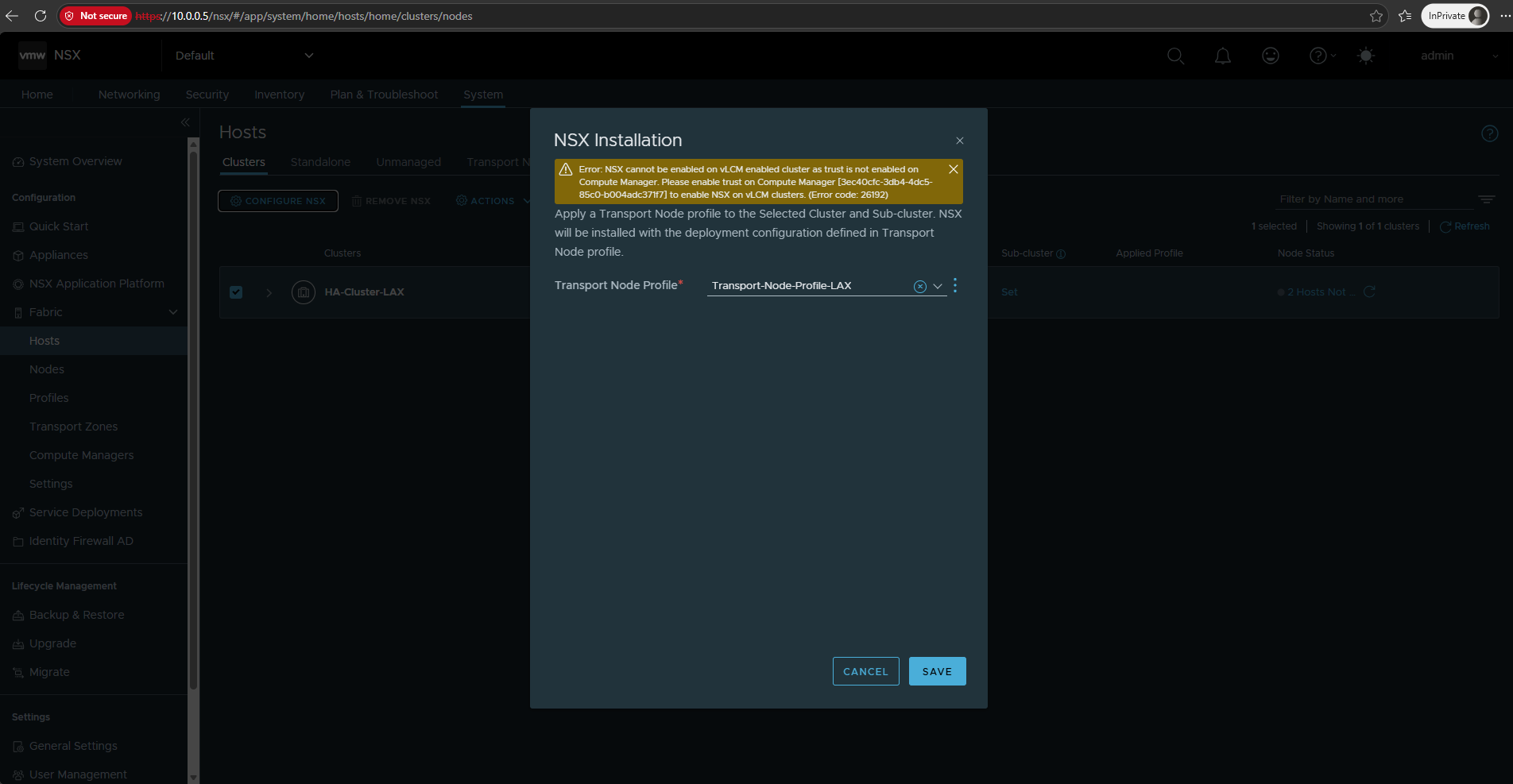
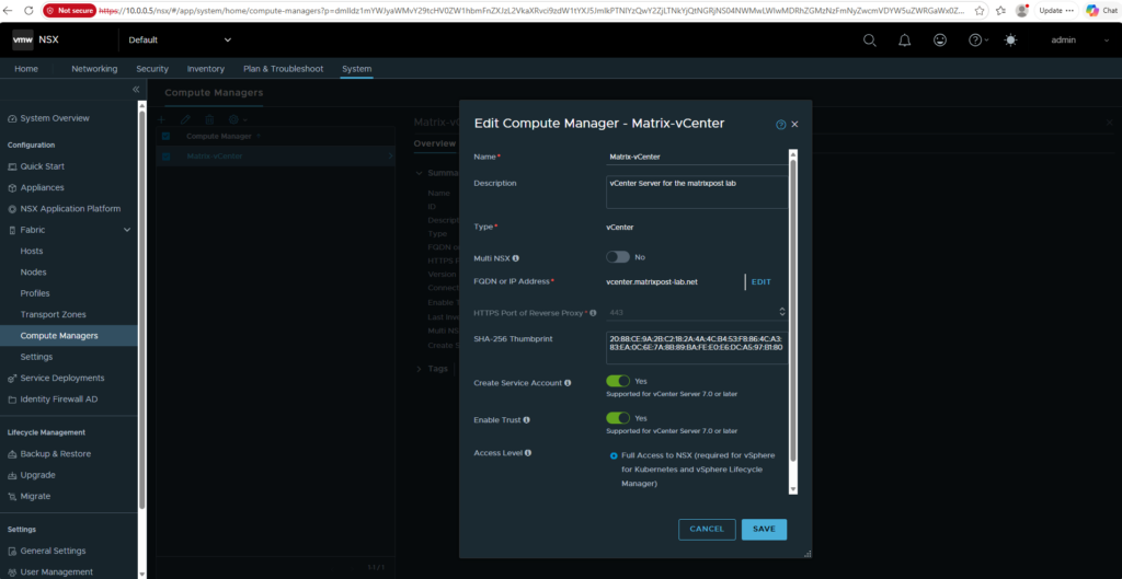
Now we need to go to System → Fabric → Compute Managers, edit Matrix-vCenter, and enable Trust.
Broadcom’s current guidance for vLCM clusters also requires Create Service Account to be enabled; after saving, wait until the Compute Manager shows Registered, then retry the cluster preparation.
Source: https://knowledge.broadcom.com/external/article/420503/cannot-disable-two-way-authentication-a.html
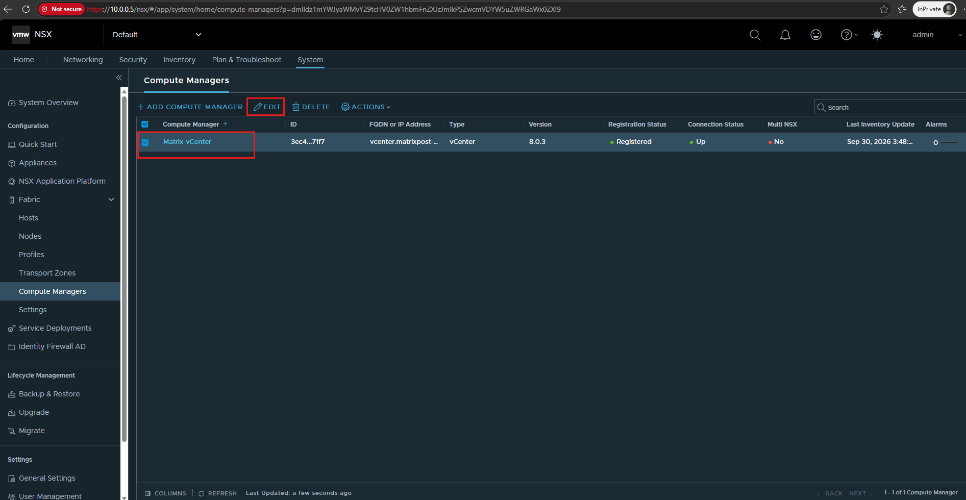
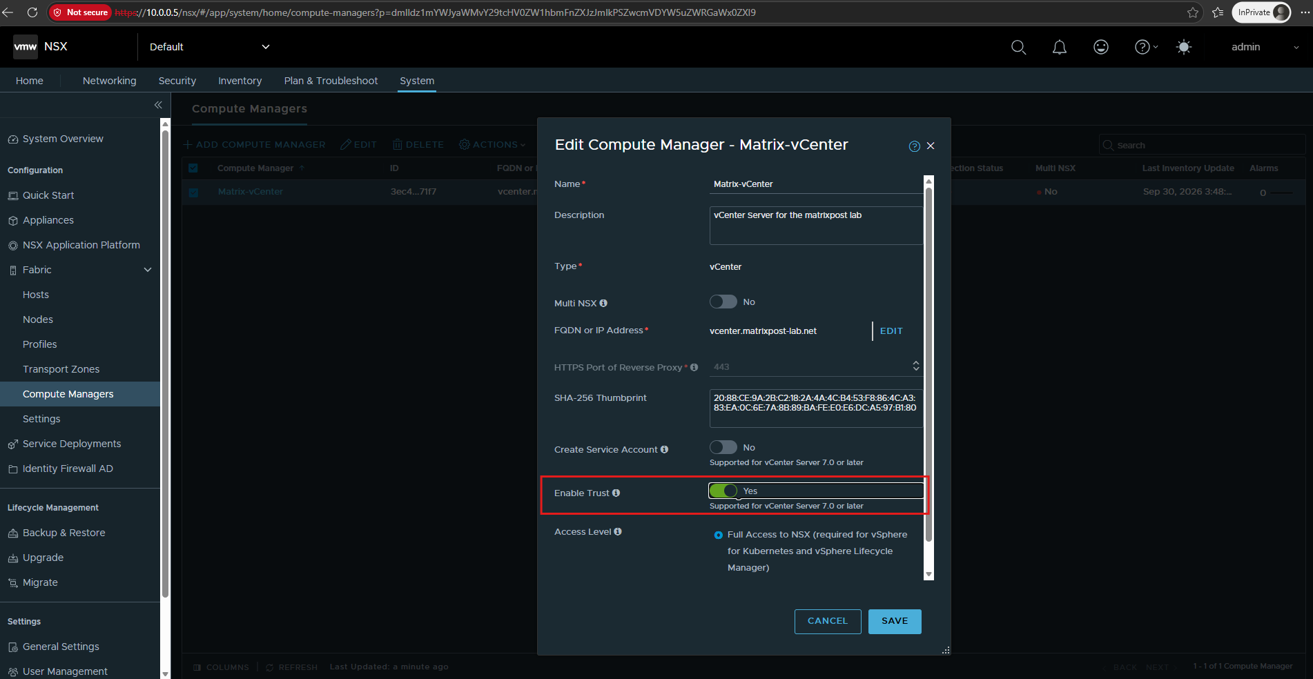
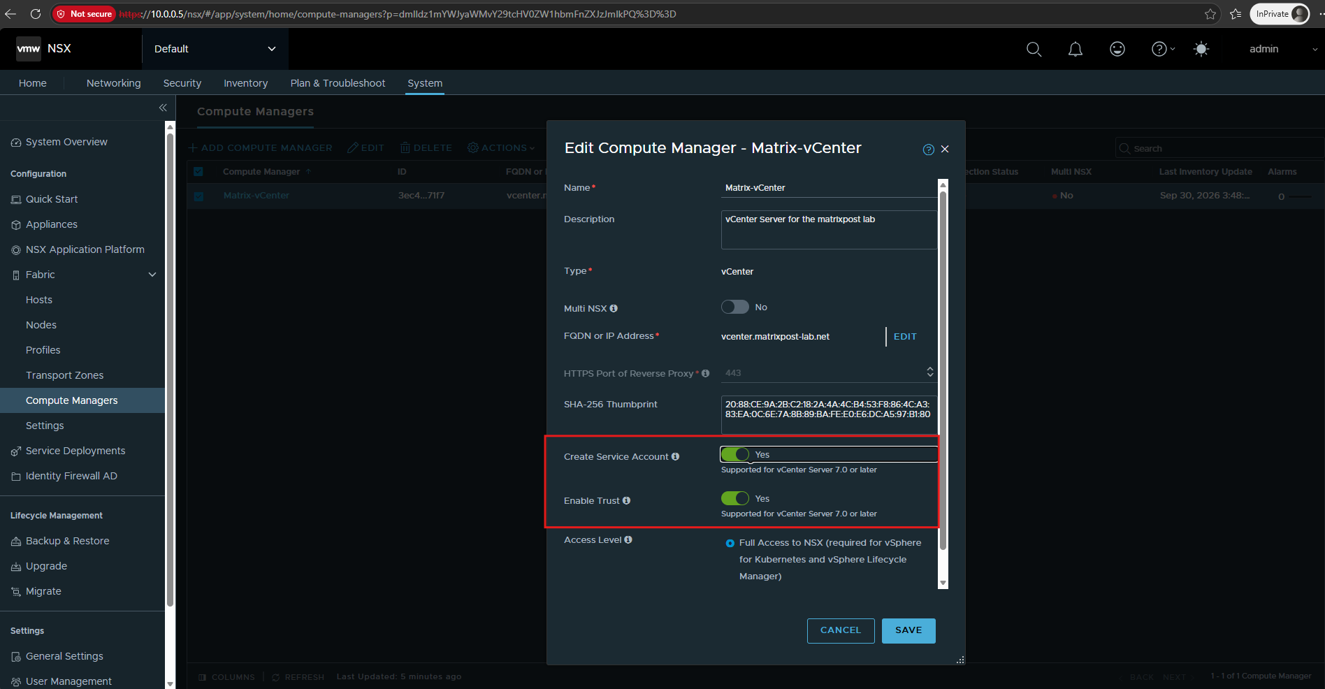
Enable Trust was disabled when we originally added Matrix-vCenter as the Compute Manager.
Toggle Enable Trust and Create Service Account on and click on SAVE.
Note: We also need to enable Create Service Account at this point. Otherwise, the subsequent NSX preparation of our vLCM-enabled cluster will fail with the error shown below.
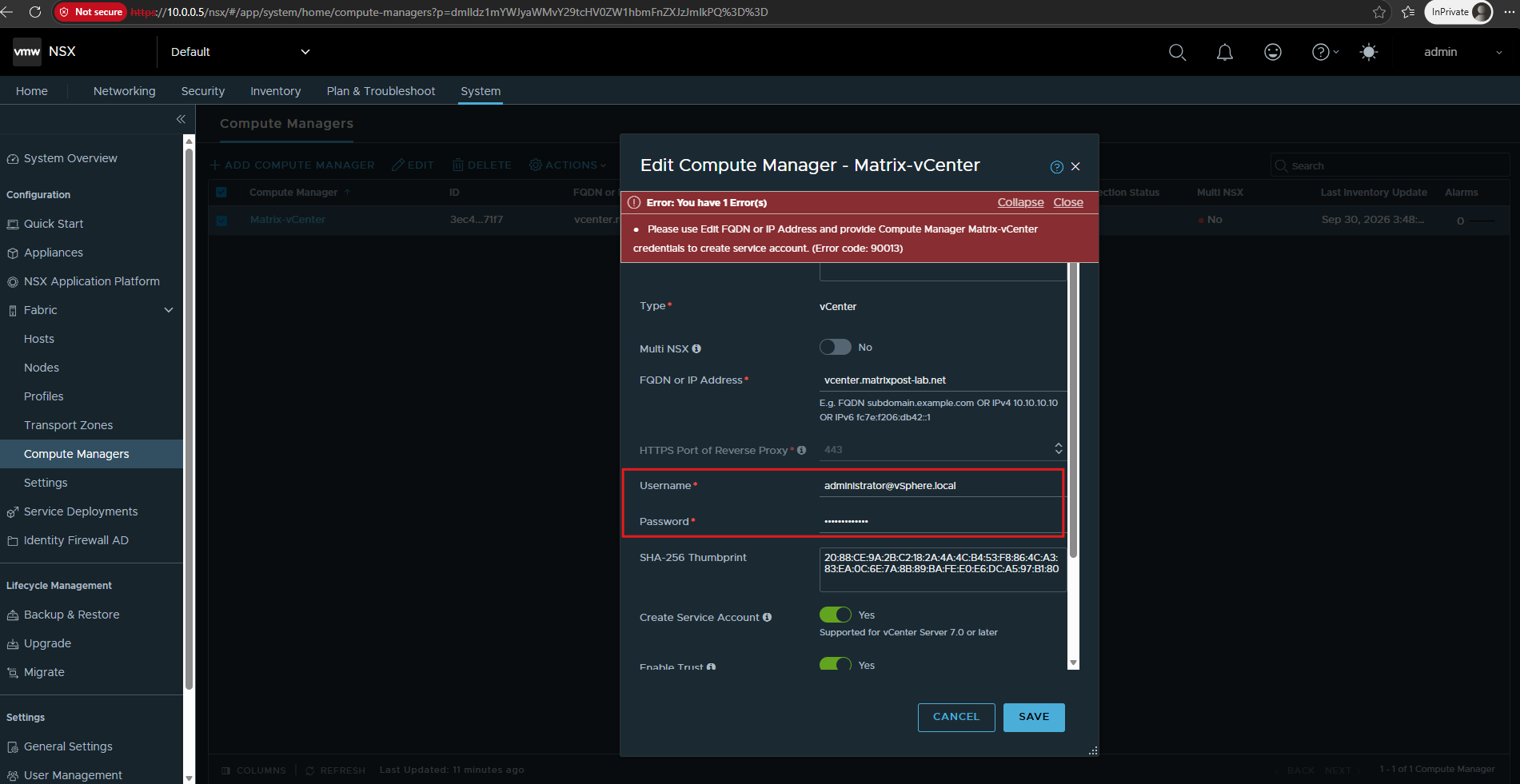
When enabling Create Service Account, NSX also requires the vCenter Server credentials again. Click Edit next to the vCenter FQDN and provide the Compute Manager credentials
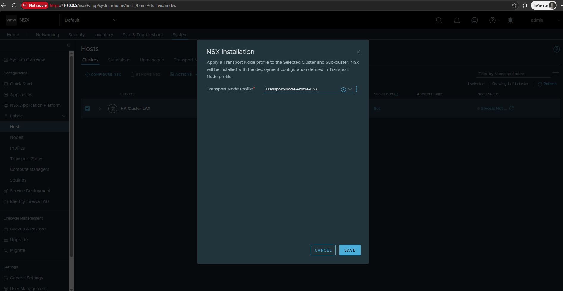
Back in the NSX Installation dialog, select Transport-Node-Profile-LAX again and click Save.
With Trust now enabled for the Compute Manager, NSX should be able to start preparing HA-Cluster-LAX and its two ESXi hosts.
We also need to enable Create Service Account for the vCenter Compute Manager. Together with Enable Trust, this is required to prepare our vLCM-enabled cluster for NSX.
Also toggle on Create Service Account.
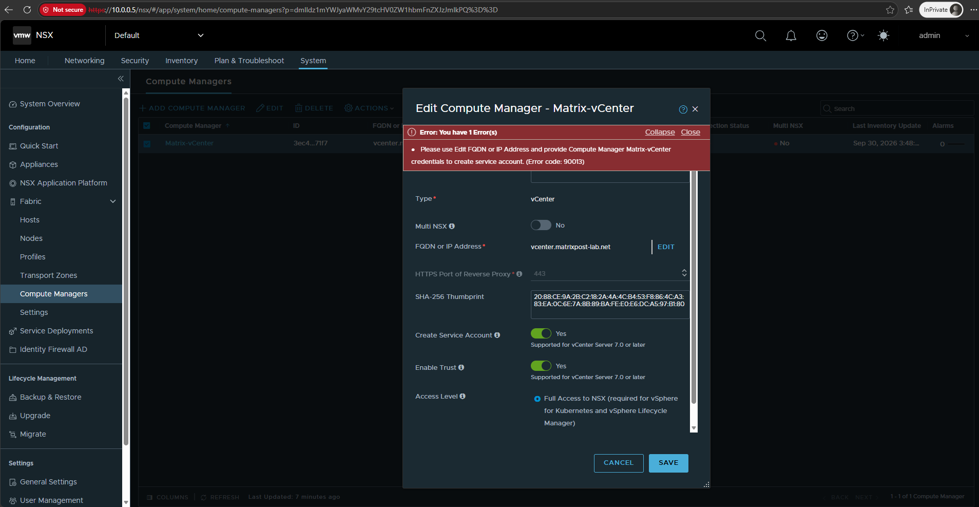
When enabling Create Service Account, NSX also requires the vCenter Server credentials again.
Click Edit next to the vCenter FQDN and provide the Compute Manager credentials; otherwise, saving fails with Error 90013.
With Enable Trust and Create Service Account now configured, return to Configure NSX and select Transport-Node-Profile-LAX again. Click Save to finally start preparing the ESXi hosts as NSX Transport Nodes.
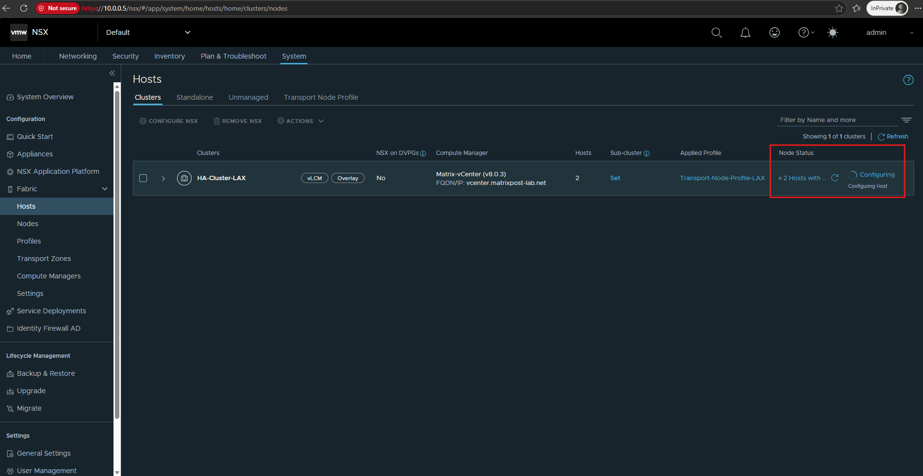
Now the Transport-Node-Profile-LAX is applied to HA-Cluster-LAX, and the node status changes to Configuring.
NSX is now preparing both ESXi hosts and configuring them according to our Transport Node Profile.
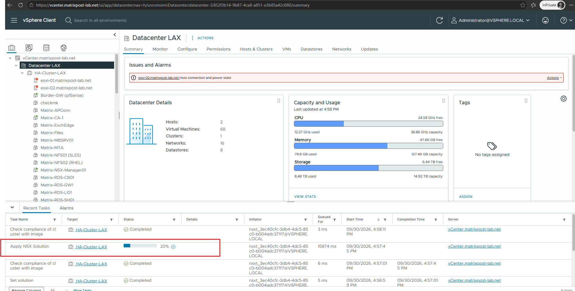
We can also monitor the preparation directly in the vSphere Client.
The Apply NSX Solution task shows vLCM applying the NSX components to HA-Cluster-LAX while the host preparation is in progress.
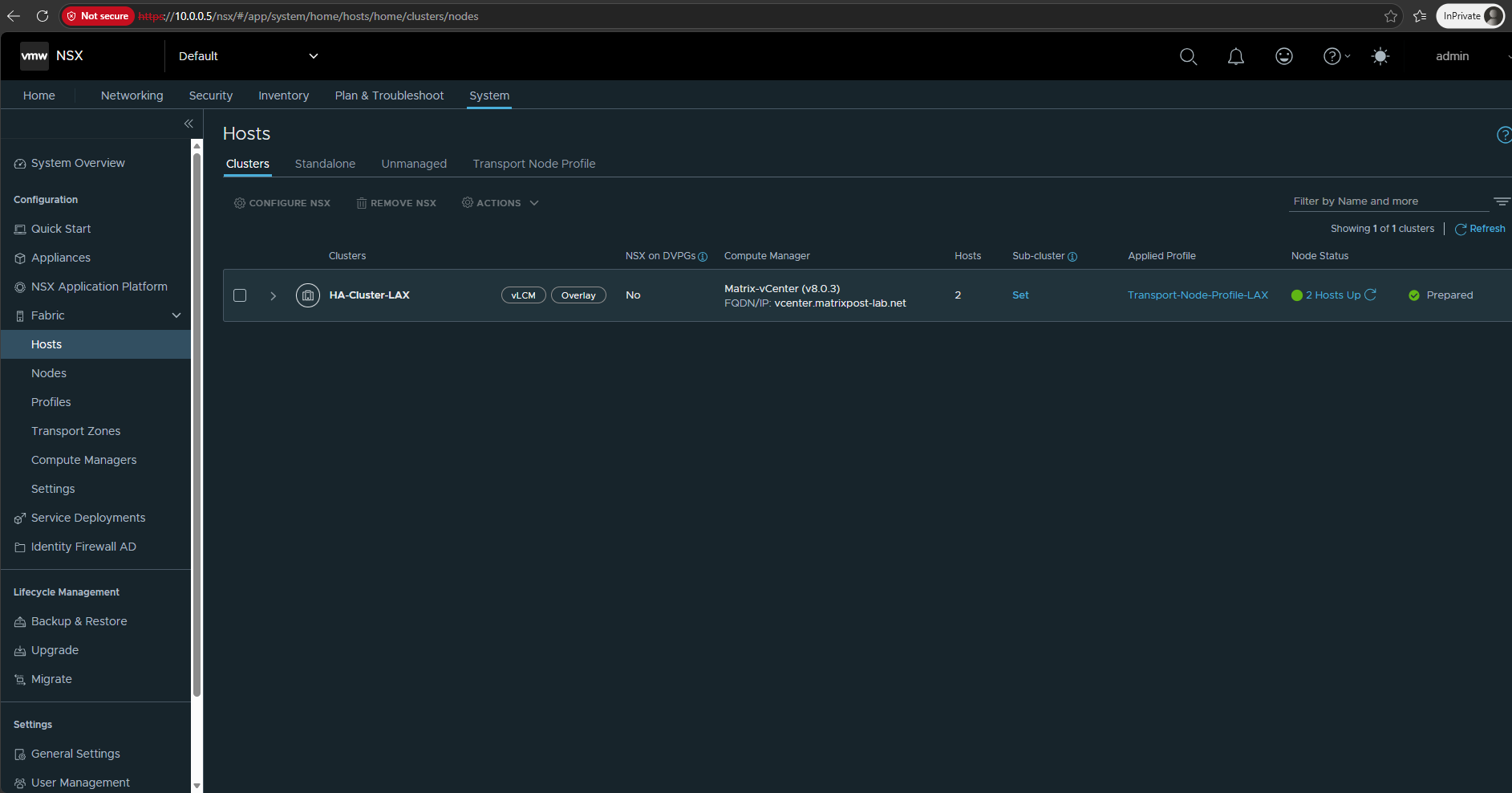
After the preparation has completed, both ESXi hosts report Up and the cluster status changes to Prepared.
Our HA-Cluster-LAX is now successfully configured with Transport-Node-Profile-LAX and ready to participate in the NSX overlay network.
Verify the Transport Nodes
After preparing the cluster, we should verify that both ESXi hosts are successfully configured as NSX Transport Nodes and that their Tunnel Endpoints (TEPs) have been created correctly.
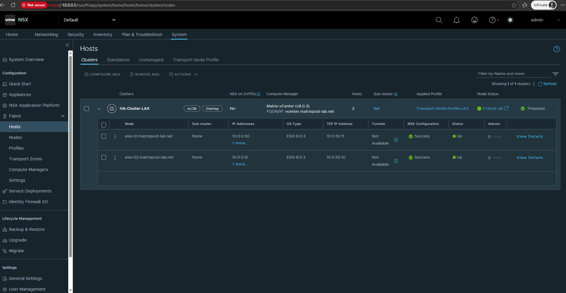
Expand HA-Cluster-LAX to verify the individual NSX Transport Nodes. Both ESXi hosts now report NSX Configuration: Success and Status: Up, and their TEP interfaces have received IP addresses
10.0.50.11and10.0.50.10from our TEP-IP-Pool-LAX.For the equivalent concept in Microsoft Hyper-V Network Virtualization (HNV), where Provider Addresses (PAs) provide the underlying transport addressing, see https://blog.matrixpost.net/hyper-v-network-virtualization-hnv-part1/#verifying_provider_address_allocation.
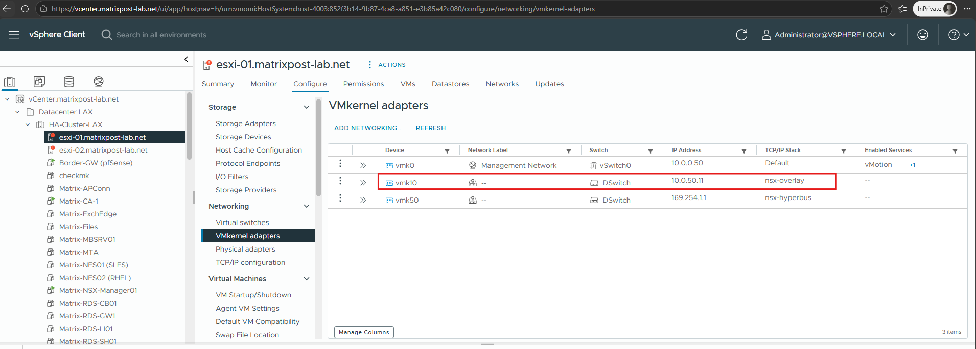
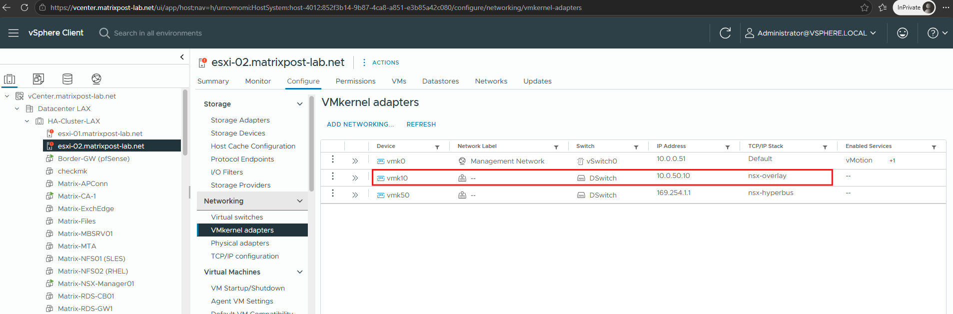
In the vSphere Client, we can also verify the TEPs directly under Configure → Networking → VMkernel adapters.
NSX created a
vmk10adapter on the DSwitch of both ESXi hosts, assigning 10.0.50.11 toesxi-01and 10.0.50.10 toesxi-02, both using the nsx-overlay TCP/IP stack.
Create the NSX Overlay Network
With the NSX transport infrastructure now configured and both ESXi hosts successfully prepared as Transport Nodes, we can move on to the logical networking layer.
We will now create our first NSX Overlay Segment and connect virtual machines to it, similar to how we previously created an isolated HNV tenant network and connected tenant VMs in our Microsoft HNV lab.
For the equivalent implementation with Microsoft Hyper-V Network Virtualization (HNV), see https://blog.matrixpost.net/hyper-v-network-virtualization-hnv-part1/#creating_tenantVM_connecting_to_HNV.
Create an NSX Overlay Segment
An NSX Segment represents a logical Layer 2 network to which virtual machines can be connected. When configured as an Overlay Segment, traffic between workloads can be transported across the physical underlay through the TEPs we configured in the previous section.
In NSX Manager, go to Networking → Segments and click Add Segment.
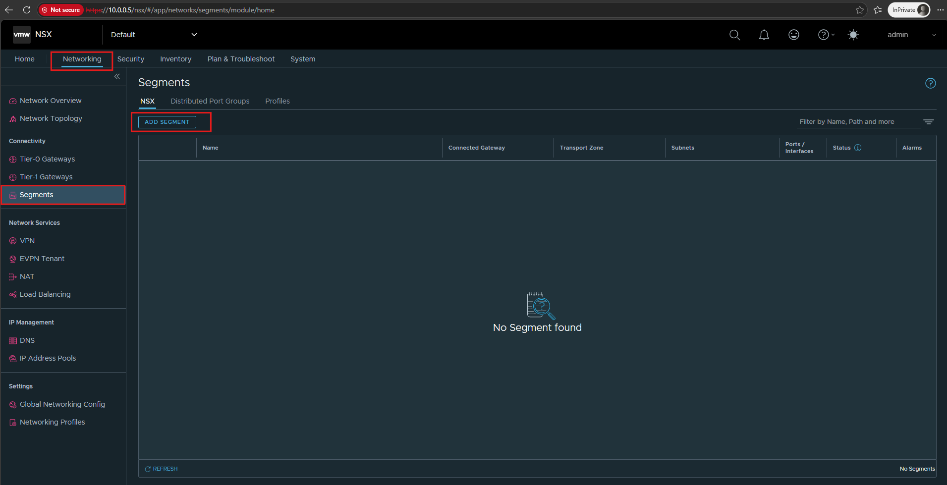
This opens the configuration for our first NSX overlay segment, which we will initially create without a connected gateway to demonstrate pure Layer 2 connectivity across the NSX overlay.
For this first segment, I will use:
- Name:
Overlay-Segment-TenantA - Connected Gateway:
None - Transport Zone:
nsx-overlay-transportzone - Subnet/Gateway: leave empty for now
- Admin State: Enabled
Because
Overlay-Segment-TenantAis currently not connected to an NSX Gateway, we do not need to configure a subnet on the segment.At this stage, the segment simply provides an isolated Layer 2 broadcast domain across our ESXi hosts. The connected virtual machines (shown below) can therefore use any IP subnet, provided they use compatible addressing when they need to communicate directly with each other.
Unlike our Microsoft HNV implementation, we do not need to define an IP address space or virtual subnet for this standalone NSX Overlay Segment. Without an attached NSX Gateway, the segment operates purely at Layer 2 and is therefore independent of the IP addressing used by the connected workloads.
In HNV, by comparison, each tenant virtual network is explicitly configured with an address space and virtual subnet. This can also be used to create completely isolated tenant networks with overlapping IP address spaces, as demonstrated in Part 4 of my HNV series.
Then click on SAVE.
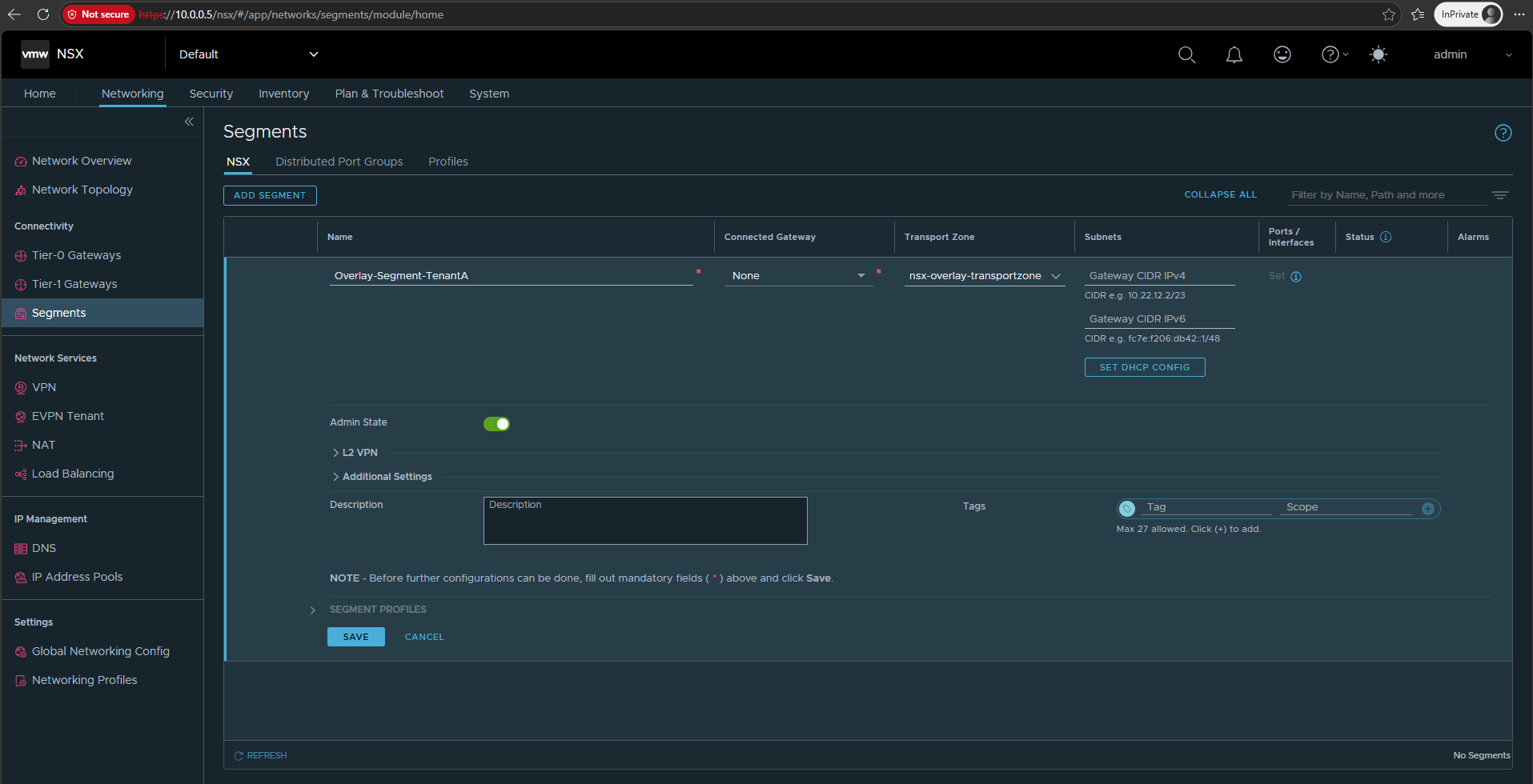
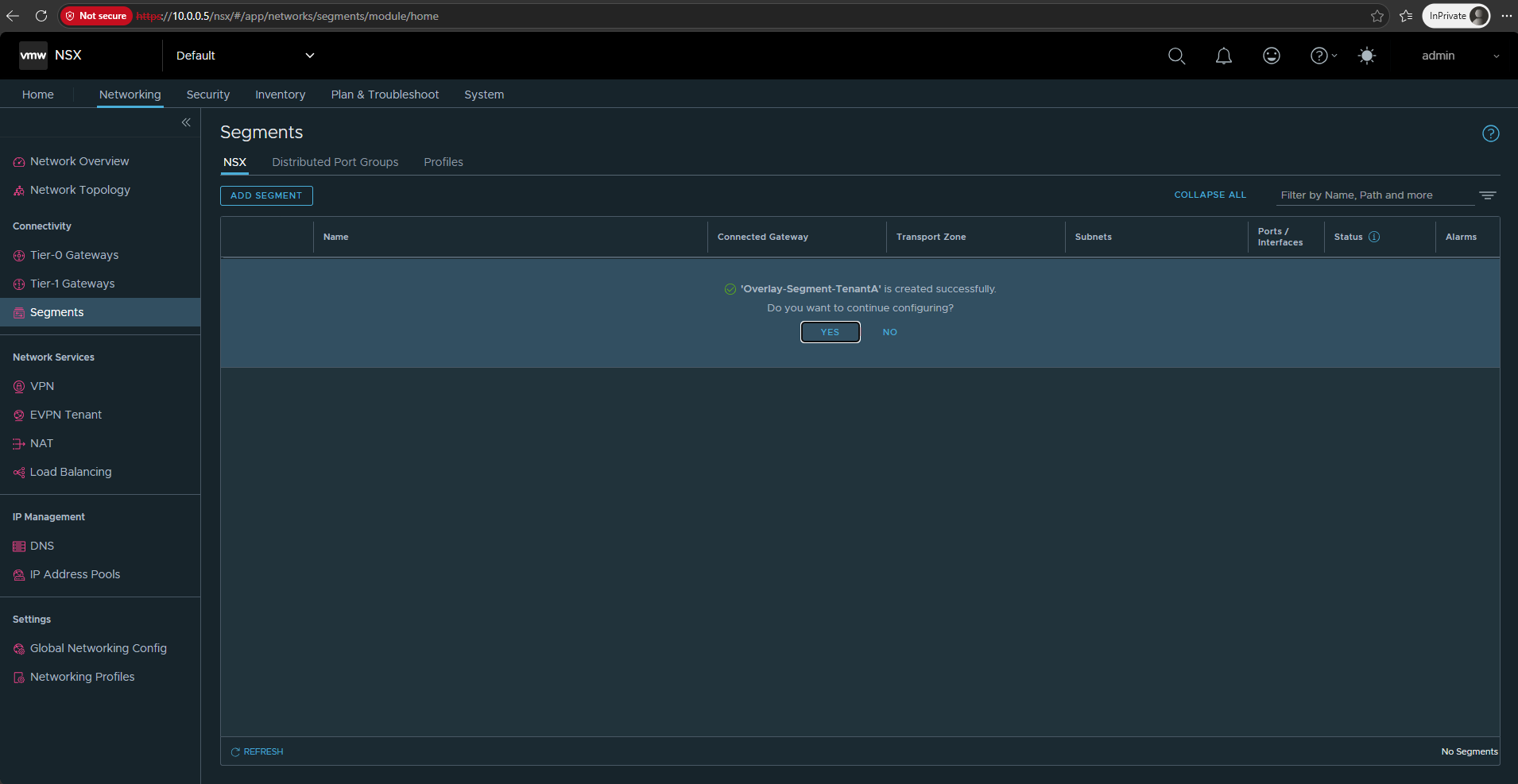
After clicking Save, NSX creates our Overlay-Segment-TenantA successfully. Since no additional configuration is required at this point, click No to finish the segment creation.
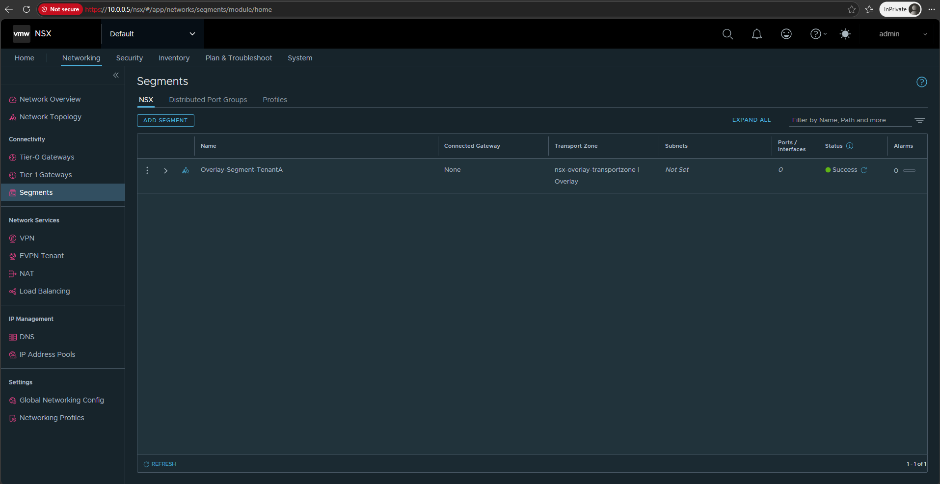
Our Overlay-Segment-TenantA is now successfully created in the nsx-overlay-transportzone.
It currently has no connected gateway or subnet, providing us with an isolated Layer 2 overlay network for our TenantA virtual machines.
Connect Virtual Machines to the NSX Overlay Segment
With Overlay-Segment-TenantA created, we can now connect virtual machines to our new NSX overlay network.
To demonstrate communication across the overlay, we will use two TenantA VMs placed on different ESXi hosts and assign them IP addresses from the same isolated subnet.
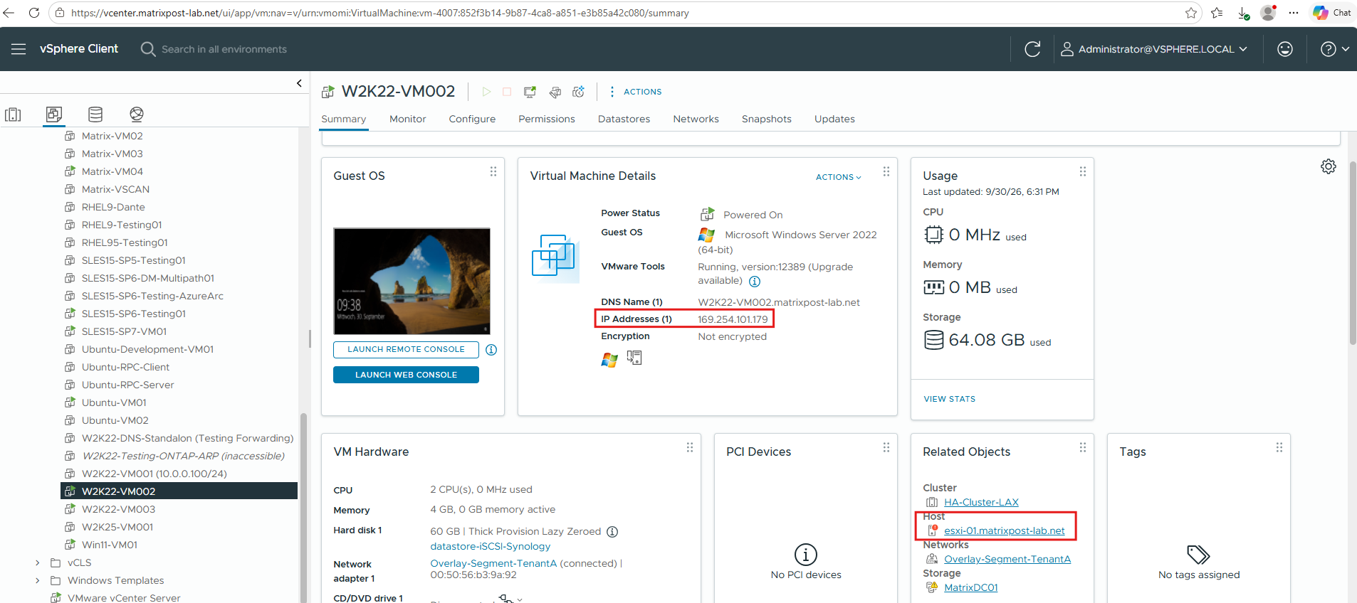
For our overlay connectivity test, I will use two existing Windows Server virtual machines and place them on different ESXi hosts.
Both VMs will be connected to Overlay-Segment-TenantA and configured with IP addresses from the same isolated 192.168.100.0/24 network.
W2K22-VM002 → placed on esxi-01 → 192.168.100.10/24
W2K22-VM003 → placed on esxi-02 → 192.168.100.11/24
Edit the network adapters of both W2K22-VM002 and W2K22-VM003 and connect them to our newly created Overlay-Segment-TenantA.
The NSX segment is exposed directly in the vSphere Client and uses our existing
DSwitchas its underlying distributed switch.The equivalent in Microsoft HNV is the Virtual Network exposed to the VM through Windows Admin Center, while the VM remains connected to the underlying Hyper-V
vSwitch-VM.In Part 1 we configured this association using PowerShell, while in Part 2 we performed the same task through Windows Admin Center (WAC).
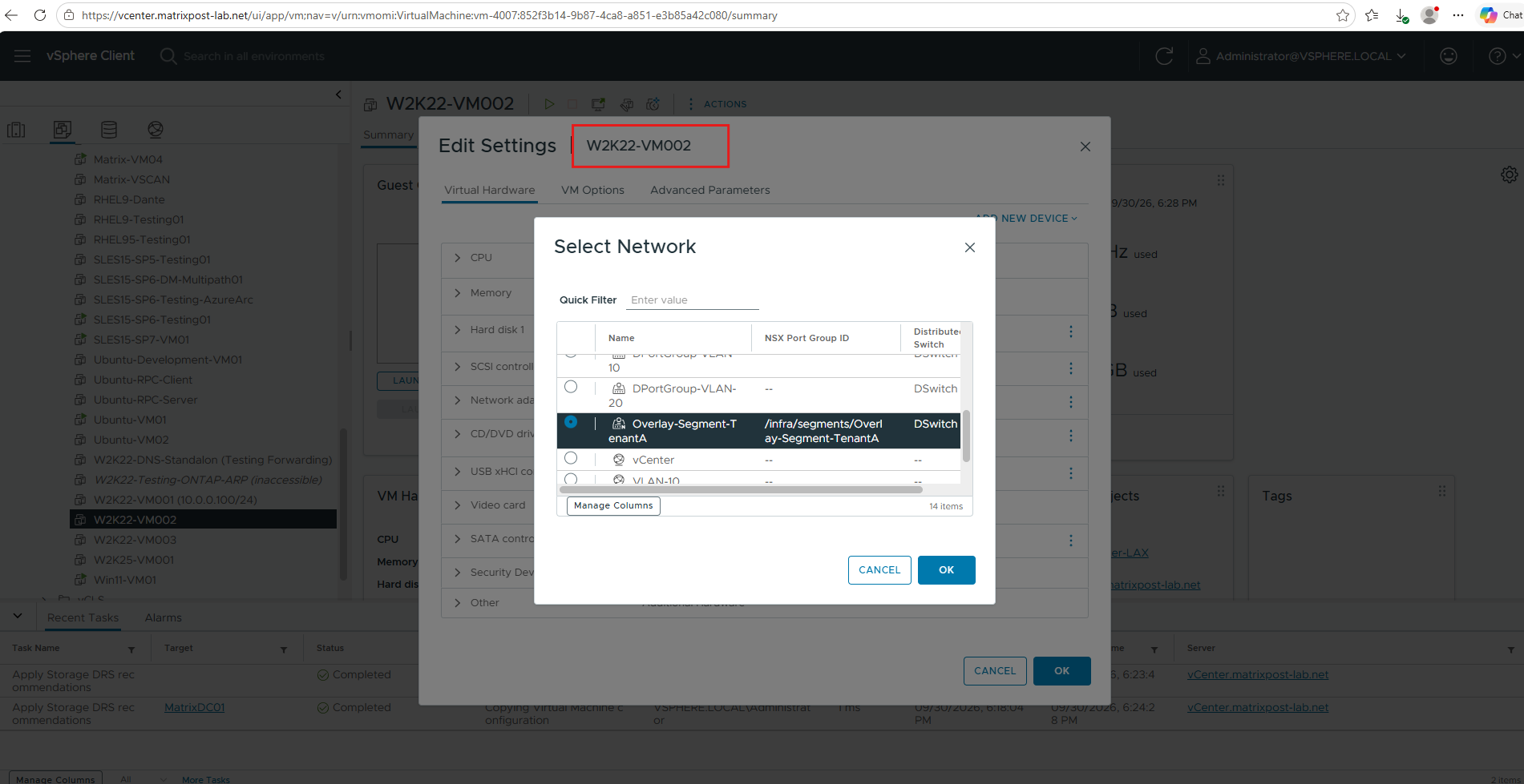
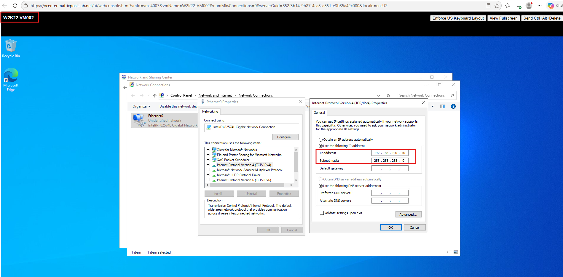
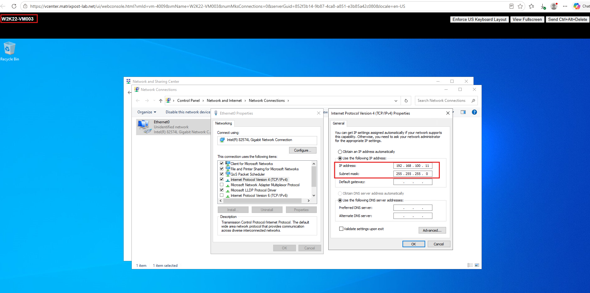
Since our Overlay-Segment-TenantA currently has no gateway or DHCP configuration, we configure the IP addresses directly inside the guest operating systems.
We assign
192.168.100.10/24toW2K22-VM002and192.168.100.11/24toW2K22-VM003; no default gateway is required for communication within the same overlay subnet.
Test the NSX Overlay Network
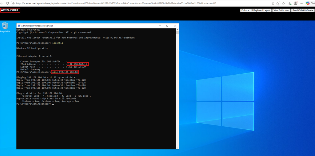
With both virtual machines connected to Overlay-Segment-TenantA and configured with IP addresses from the same 192.168.100.0/24 subnet, we can now verify.
From W2K22-VM003 (192.168.100.11), we ping W2K22-VM002 (192.168.100.10).
The successful replies confirm Layer 2 connectivity between the two TenantA virtual machines running on different ESXi hosts.
Capture the NSX Overlay Traffic
Now that communication between the two TenantA VMs has been verified, we can take a closer look at how NSX transports this traffic across the physical network.
We will capture the traffic on the ESXi hosts and examine the encapsulated packets exchanged between their TEP addresses 10.0.50.11 and 10.0.50.10.
Before starting the capture, first identify the available physical network adapters on esxi-02 using the esxcli command below.
In my lab, the host provides the three USB-based network adapters
vusb0,vusb1, andvusb2.
esxcli network nic list
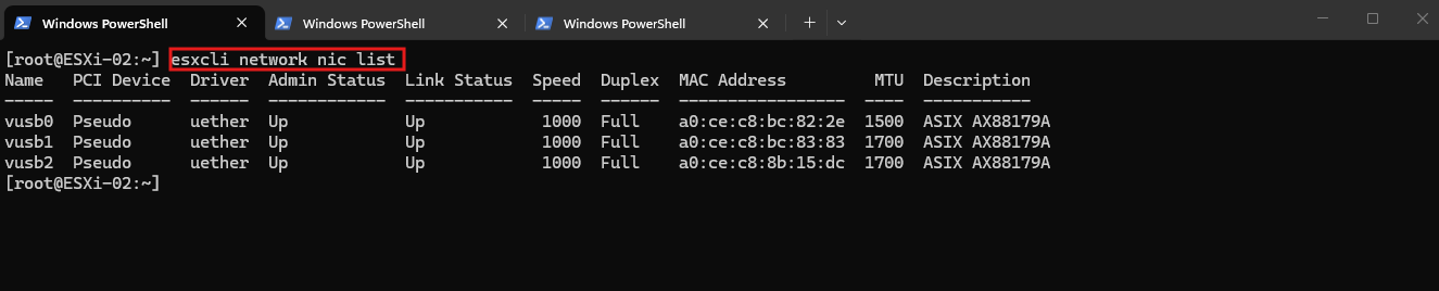
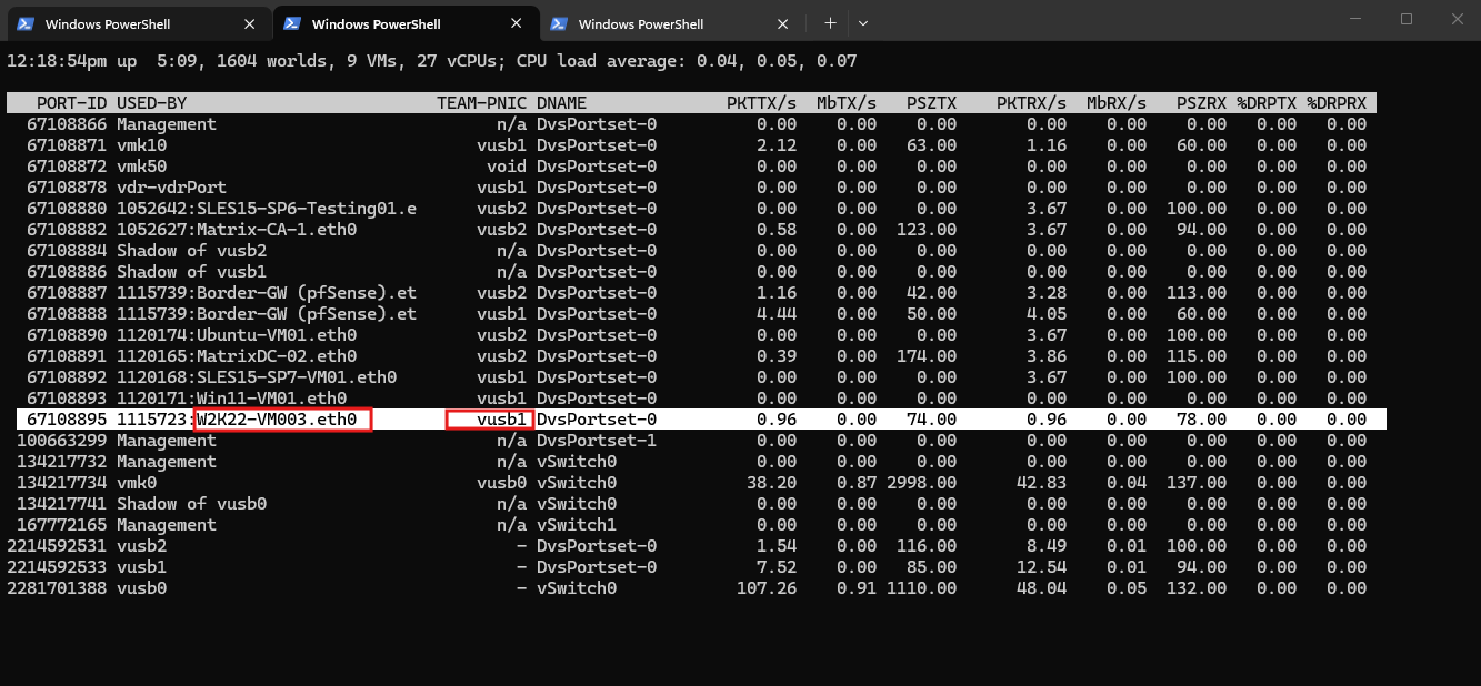
Next, use the esxtop utility and press n to display the networking view.
The TEAM-PNIC column shows which physical uplink is currently used; for the NSX TEP adapter
vmk10onesxi-02, this isvusb1.For more details about identifying the physical uplink with
esxtop, see my article https://blog.matrixpost.net/how-to-determine-which-uplink-physical-nic-a-virtual-machine-is-using-finally-to-send-uplink-traffic-in-vsphere/.
esxtop
next press n
Now start the packet capture on the identified physical uplink vusb1 using pktcap-uw.
We capture traffic in both directions with the
UplinkSndKernelandUplinkRcvKernelcapture points and write the result to/tmp/nsx-overlay.pcapfor later analysis in Wireshark.
pktcap-uw --uplink vusb1 --capture UplinkSndKernel,UplinkRcvKernel -o /tmp/nsx-overlay.pcap
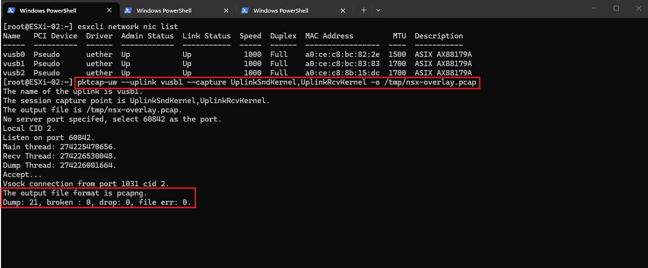
While the capture is running, generate traffic between the two TenantA VMs and stop the capture with Ctrl+C after a few packets have been collected.
We can then download the resulting /tmp/nsx-overlay.pcap file from the ESXi host using SFTP and open it in Wireshark for further analysis.
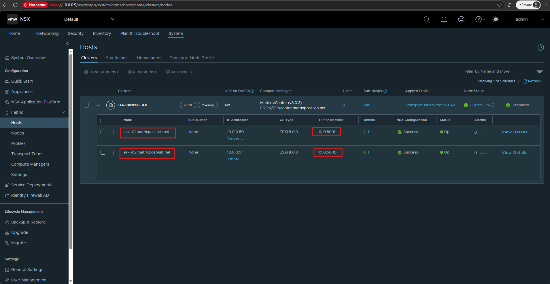
Before analyzing the captured traffic in Wireshark, let’s first verify which TEP IP address belongs to each ESXi host under VMware NSX Manager → System → Fabric → Hosts → Clusters .
In our lab,
esxi-01uses 10.0.50.11 andesxi-02uses 10.0.50.10.
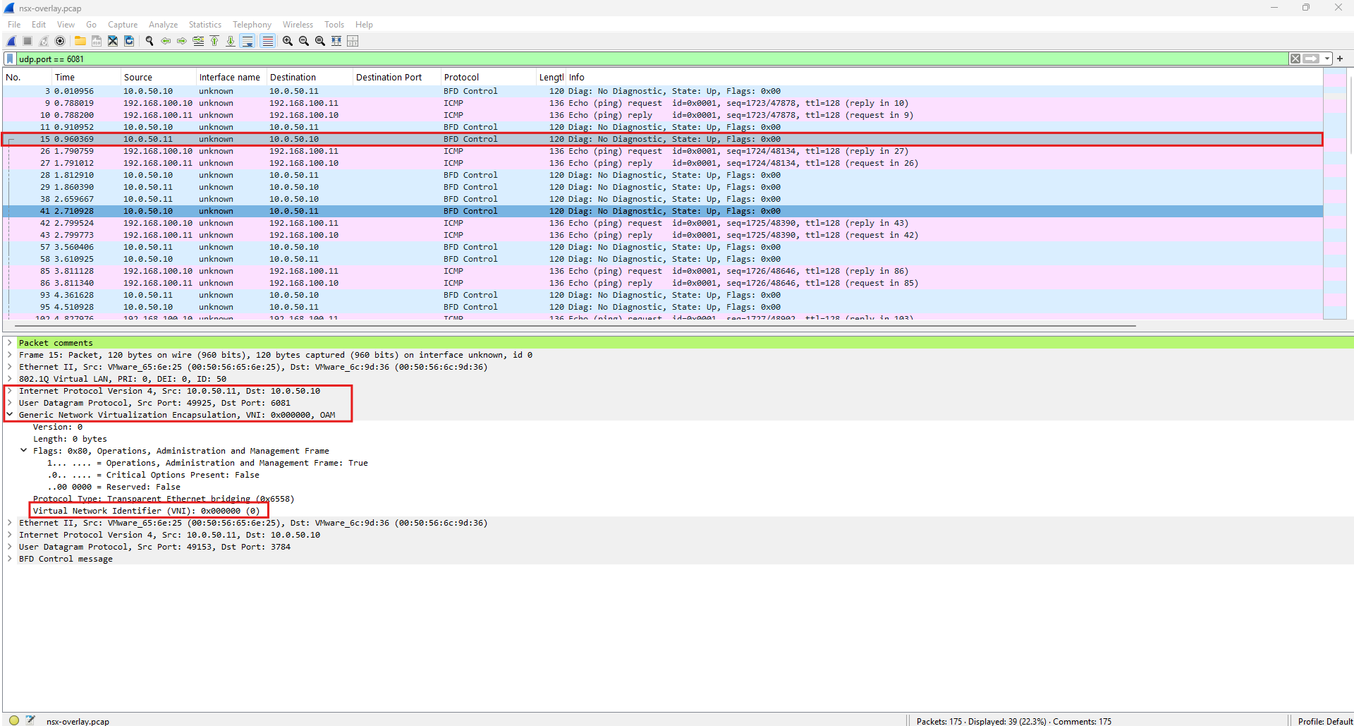
Filtering the capture for UDP port 6081 reveals the GENEVE-encapsulated traffic exchanged between our NSX TEPs.
The selected frame (Layer 2 Ethernet data unit) is sent from 10.0.50.11 (
esxi-01) to 10.0.50.10 (esxi-02) using UDP port6081and is identified by Wireshark as Generic Network Virtualization Encapsulation (GENEVE).However, this particular packet (Layer 3 IP data unit) is not our encapsulated TenantA workload traffic. It is an NSX OAM/BFD control packet used between the TEPs, which is why the GENEVE header has the OAM flag set and shows VNI 0.
BFD (Bidirectional Forwarding Detection) is a lightweight protocol used by NSX to rapidly detect connectivity failures between tunnel endpoints (TEPs).
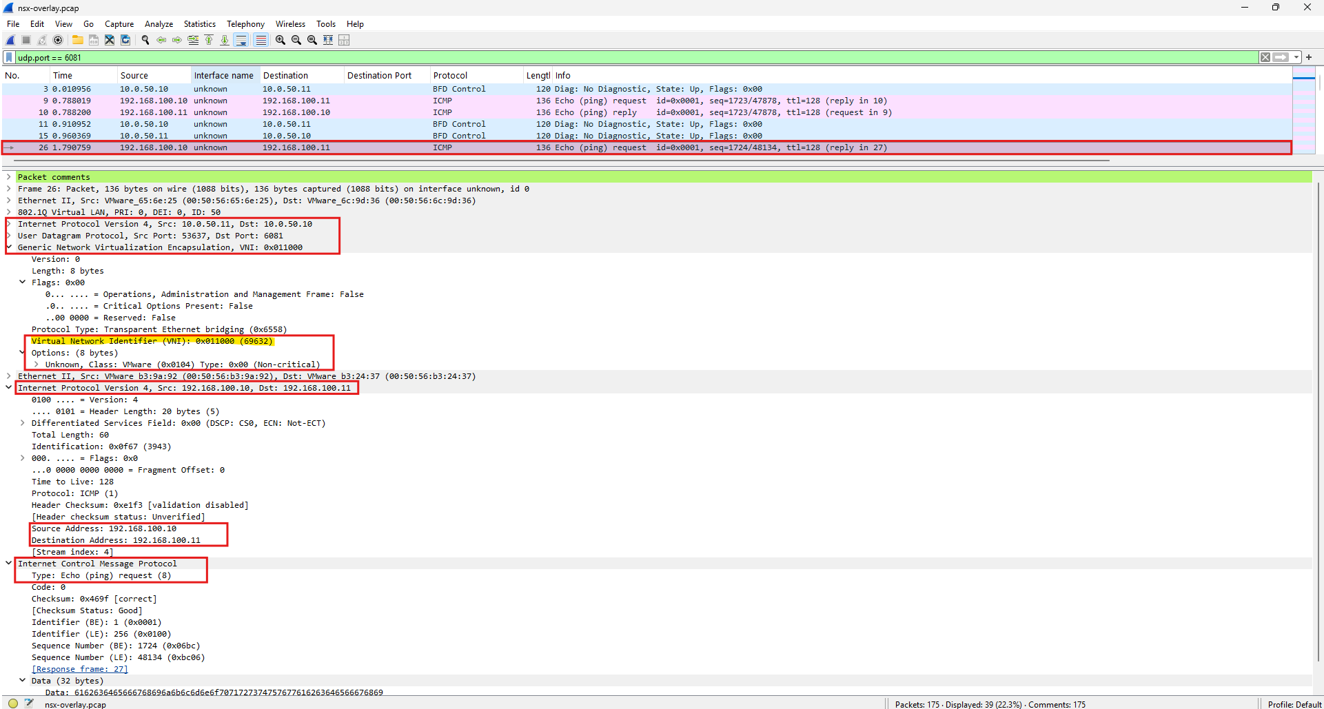
Next, we will examine one of our ICMP packets between the TenantA VMs and see the actual overlay segment VNI.
udp.port == 6081
Frame 26 shows the actual TenantA ICMP traffic encapsulated by NSX using GENEVE.
The outer IP header transports the frame between the TEPs
10.0.50.11 (esxi-01) → 10.0.50.10 (esxi-02)over UDP 6081, while the GENEVE header identifies our overlay network with VNI0x011000(69632).The GENEVE header also contains a VMware-specific option (
Class 0x0104) used to carry additional NSX metadata.Wireshark recognizes the VMware option class but does not decode this particular option further, therefore displaying it as Unknown.
Inside the encapsulation, we can see the original ICMP Echo Request from 192.168.100.10 (
W2K22-VM002) → 192.168.100.11 (W2K22-VM003).
HNV v1 in Windows Server 2012/2012 R2 originally used NVGRE, Network Virtualization using Generic Routing Encapsulation. Later Microsoft moved toward VXLAN, which is what I used in my HNV lab and shown in my Hyper-V Network Virtualization (HNV) series.
And now VMware NSX gives us the third member of the encapsulation zoo: GENEVE, Generic Network Virtualization Encapsulation.
Conceptually, all three solve essentially the same problem:
| Overlay | Encapsulation | Transport | Typical association |
|---|---|---|---|
| NVGRE | GRE-based | IP protocol 47 | Original Microsoft HNV |
| VXLAN | VXLAN | UDP 4789 | Modern HNV, older VMware NSX-V, many SDN platforms |
| GENEVE | GENEVE | UDP 6081 | Modern VMware NSX |
VXLAN essentially says:
“Take this Ethernet frame, identify its logical overlay using a 24-bit VNI, wrap it in UDP/IP, and transport it between tunnel endpoints.”
GENEVE does essentially the same thing:
“Take this Ethernet frame, identify its logical overlay using a 24-bit VNI, wrap it in UDP/IP, and transport it between tunnel endpoints.”
But GENEVE was designed with an extensible options/metadata mechanism. An SDN platform such as NSX can therefore carry additional information in the encapsulation rather than being constrained to the relatively fixed VXLAN header.
So for our exact packet:
W2K22-VM002
192.168.100.10
      │
      │ Original Ethernet/IP/ICMP packet
      ▼
ESXi-01
TEP 10.0.50.11
      │
      │ GENEVE encapsulation
      │ UDP 6081
      ▼
Physical Underlay Network
      │
      ▼
ESXi-02
TEP 10.0.50.10
      │
      │ GENEVE decapsulation
      ▼
W2K22-VM003
192.168.100.11
Links
Updating NSX Compute Manager from IP Address to FQDN
https://knowledge.broadcom.com/external/article/426973/updating-nsx-compute-manager-from-ip-add.htmlVMware vSphere NSX overview
https://cloud.ibm.com/docs/vmwareCannot disable two way authentication and service account creation functionality.(Error code: 26707)
https://knowledge.broadcom.com/external/article/420503/cannot-disable-two-way-authentication-a.html