Windows Server Software Defined Networking (SDN) and Hyper-V Network Virtualization (HNV) – Part 4: Testing HNV Isolation with Overlapping Tenant Networks
In Part 3 of this series, we extended our HNV environment beyond the isolated tenant network and provided external connectivity through the native Microsoft SDN Gateway and our upstream pfSense router. This allowed workloads in Tenant-CustomerA to communicate with external networks and ultimately reach the Internet.
So far, however, we have worked with only a single tenant network. One of the key capabilities of Hyper-V Network Virtualization (HNV) is the ability to create multiple isolated virtual networks that can use overlapping Customer Address (CA) spaces on the same physical SDN infrastructure.
In this fourth part, we will put this capability to the test by creating a second tenant, Tenant-CustomerB, and deliberately assigning it the same 192.168.100.0/24 address space already used by Tenant-CustomerA. We will deploy workloads with overlapping IP addresses and verify that HNV keeps the two tenant networks completely isolated from each other.
Finally, we will examine how the Network Controller, HNV and VXLAN distinguish traffic belonging to the two tenants despite their identical IP addressing, demonstrating one of the fundamental advantages of network virtualization in multi-tenant environments.
In Part 5, we will extend these overlapping networks beyond the HNV fabric using Linux VRFs (Virtual Routing and Forwarding) while allowing both tenants to share the same Internet connection.
In Part 6, we will extend the overlapping tenant networks even further by connecting each HNV tenant to a separate Azure Virtual Network (VNet) through its own Site-to-Site IPsec VPN, using XFRM interfaces and Linux VRFs to preserve the individual tenant routing contexts. XFRM interfaces were introduced to overcome design limitations of the existing Linux VTI devices and provide a more flexible interface-based approach for IPsec processing.
Creating a Second HNV Tenant Network with Overlapping IP Addresses
We will start by creating a second isolated HNV tenant network named Tenant-CustomerB. To demonstrate one of the fundamental capabilities of Hyper-V Network Virtualization, we deliberately configure this tenant with the same 192.168.100.0/24 Customer Address (CA) space already used by Tenant-CustomerA.
Although both tenant networks use identical IP addressing, the Network Controller and HNV data plane treat them as separate virtual networks, allowing their workloads to coexist on the same physical SDN infrastructure without sharing the same Layer-2 or Layer-3 tenant network.
In Part 1, we created our first HNV tenant network, Tenant-CustomerA, using PowerShell and the Network Controller API. This time, we will create the complete Tenant-CustomerB virtual network and its subnet using Windows Admin Center (WAC), demonstrating the graphical alternative for provisioning HNV tenant networks through the Network Controller.
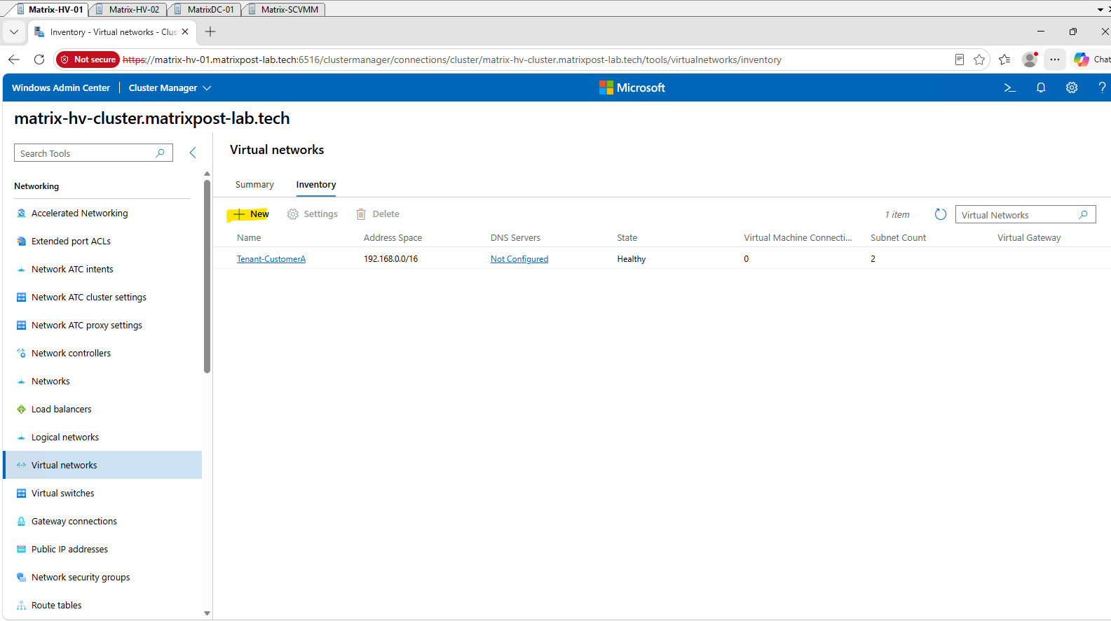
In Windows Admin Center → Virtual networks → Inventory, click New. This is where we’ll create Tenant-CustomerB as a completely separate Network Controller virtual network.
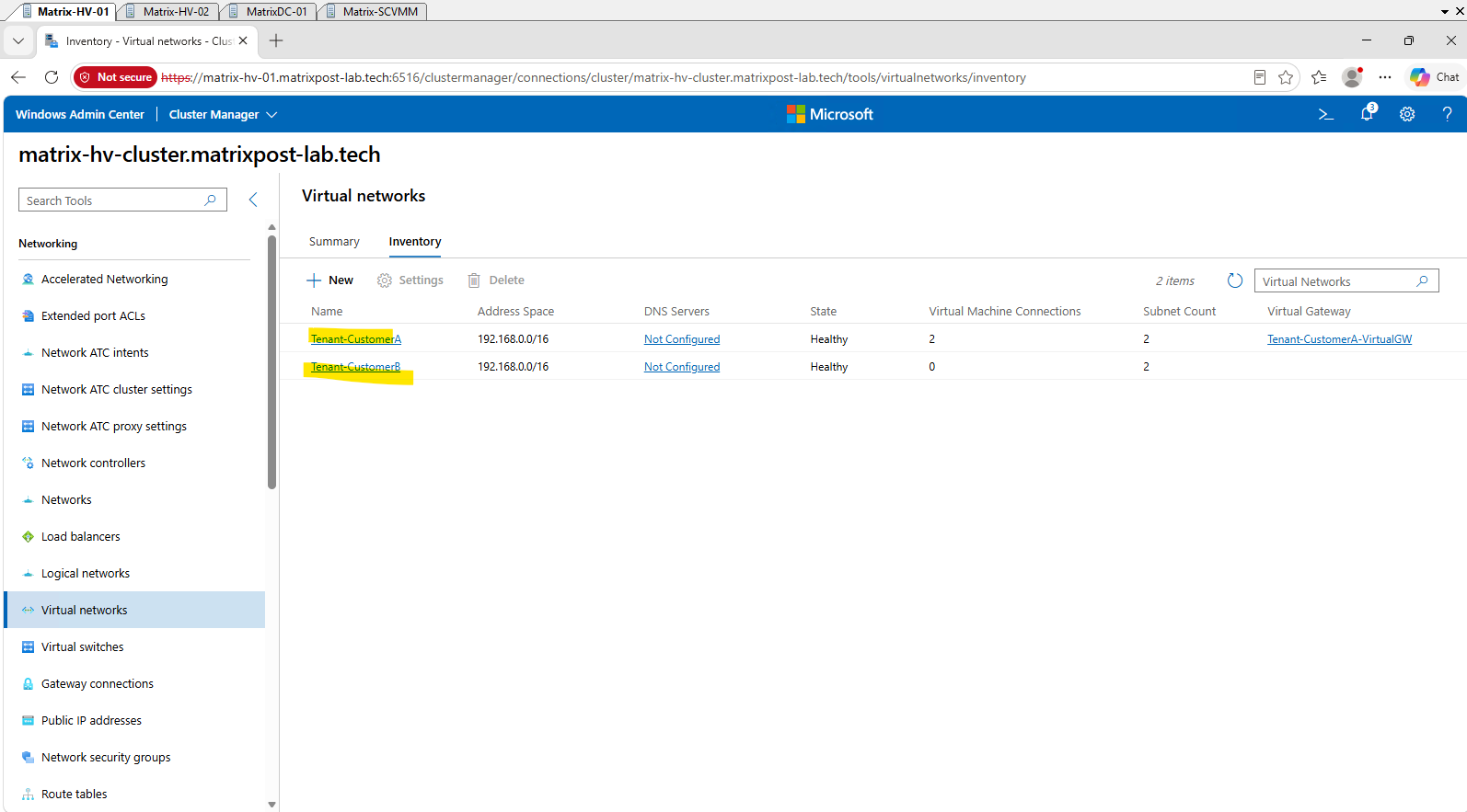
Here we can already see our existing first HNV tenant network,
Tenant-CustomerA, which we created in Part 1.
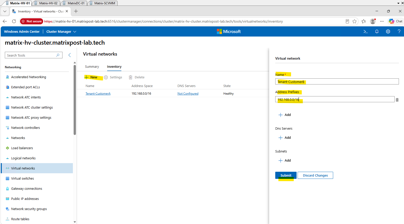
Next, enter Tenant-CustomerB as the virtual network name and configure 192.168.0.0/16 as its address space, matching the address space used by Tenant-CustomerA.
We leave DNS Servers unconfigured for our lab. The actual
192.168.100.0/24tenant subnet will be added separately in the next step, so we can submit the virtual network first.
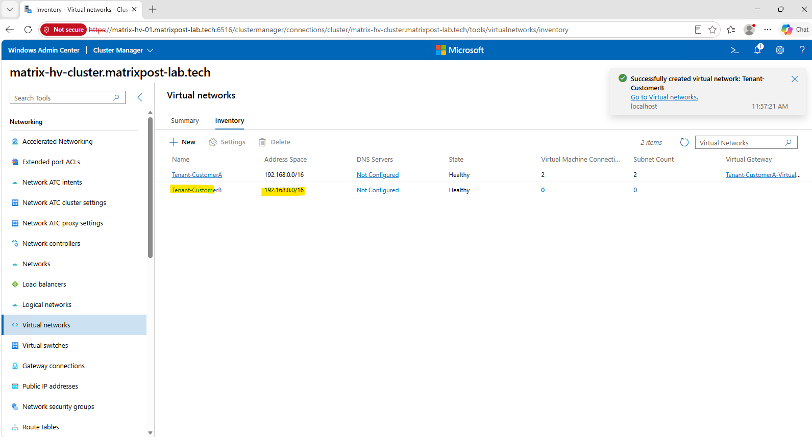
After submitting the configuration, Tenant-CustomerB appears alongside our existing Tenant-CustomerA virtual network with a Healthy state. Both virtual networks now use the identical 192.168.0.0/16 address space, while remaining completely separate HNV tenant networks. Next, we will add the overlapping 192.168.100.0/24 tenant subnet to Tenant-CustomerB.
Notice that Windows Admin Center does not report any conflict or warning about the overlapping address spaces, because the two address spaces belong to separate isolated HNV virtual networks.
Next, we will take this one step further and configure the same
192.168.100.0/24tenant subnet inTenant-CustomerB.
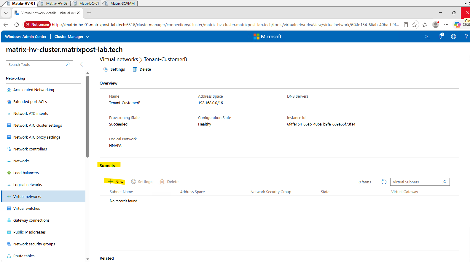
Open Tenant-CustomerB to display its virtual network details. The network is already associated with our HNVPA logical network, while no virtual subnets exist yet.
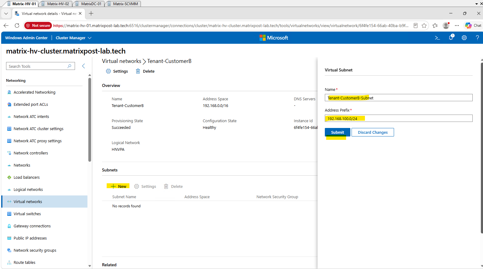
Under Subnets, click New to create the tenant subnet using the overlapping 192.168.100.0/24 Customer Address space.
Next, we create the virtual subnet Tenant-CustomerB-Subnet and deliberately configure 192.168.100.0/24 as its address prefix, the exact same Customer Address subnet already used by Tenant-CustomerA.
Click Submit to create the overlapping tenant subnet.
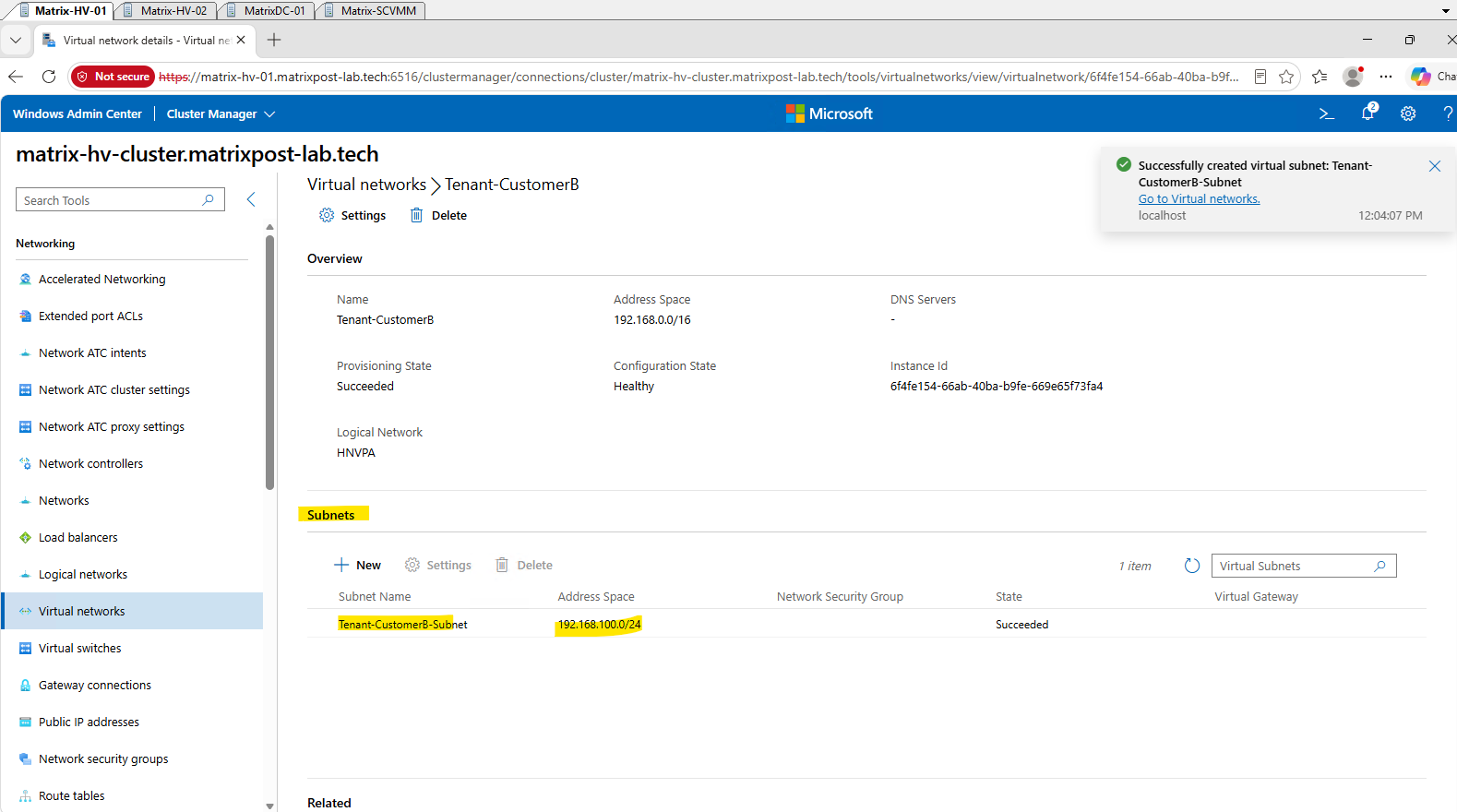
The overlapping subnet is created successfully and appears with a Succeeded state. Windows Admin Center again accepts the configuration without any address-conflict warning, even though Tenant-CustomerA and Tenant-CustomerB now both contain a 192.168.100.0/24 tenant subnet.
The identical Customer Address spaces remain isolated because they belong to separate HNV virtual networks.
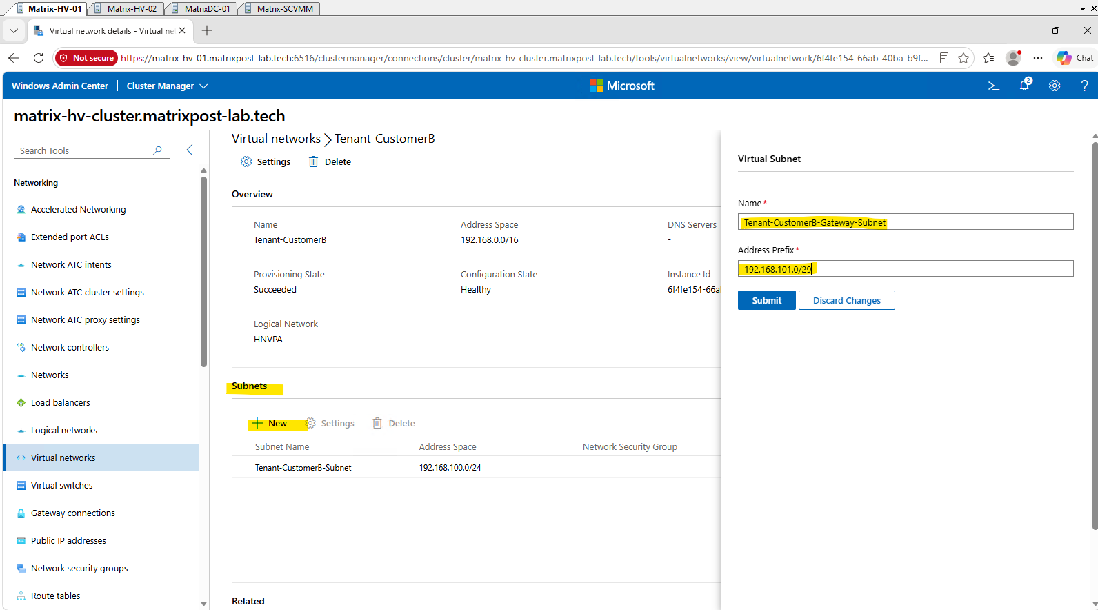
Before leaving the virtual network configuration, we also create the gateway subnet that will later be used to connect Tenant-CustomerB to its own virtual gateway.
Just as with the tenant subnet, we deliberately reuse the same
192.168.101.0/29address space already configured forTenant-CustomerA, further demonstrating that overlapping Customer Address spaces can exist independently in separate HNV virtual networks.
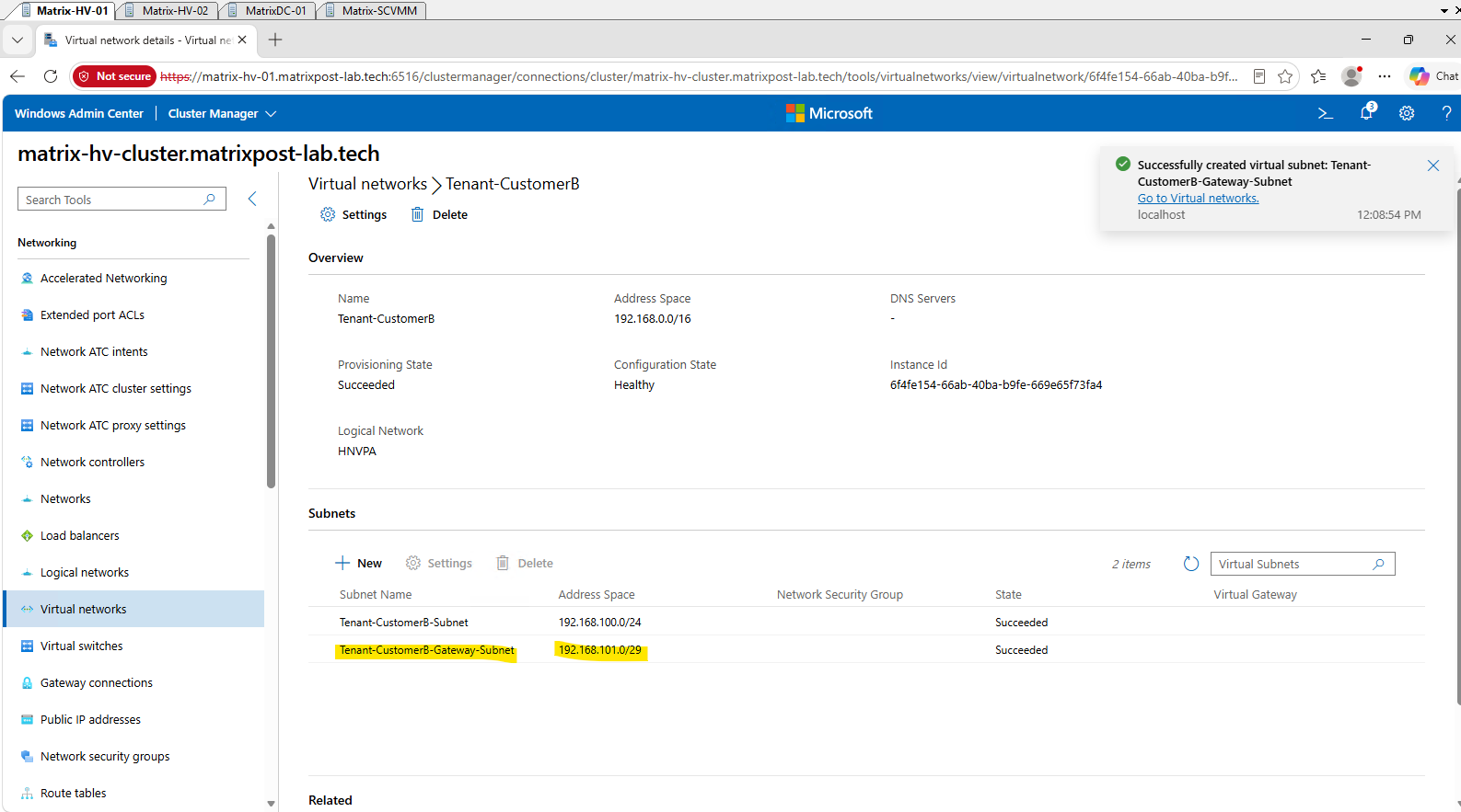
The second subnet, Tenant-CustomerB-Gateway-Subnet, is also created successfully using 192.168.101.0/29, the same gateway subnet address space used by Tenant-CustomerA. Tenant-CustomerB now contains two overlapping Customer Address subnets, 192.168.100.0/24 for tenant workloads and 192.168.101.0/29 for the virtual gateway, both provisioned successfully and independently from Customer A.
Both HNV virtual networks now appear Healthy in Windows Admin Center and use the identical 192.168.0.0/16 address space, with two subnets configured for each tenant.
Tenant-CustomerBcurrently has no VM connections or virtual gateway, which we will configure next.
Creating the First Tenant-CustomerB Workload VM
With the second HNV tenant network in place, we can now deploy our first workload for Tenant-CustomerB.
We will connect this VM to Tenant-CustomerB-Subnet and deliberately configure it with an IP address from the same 192.168.100.0/24 Customer Address space already used by the Customer A workloads.
I will not repeat the VM deployment process using SCVMM here, as the procedure is identical to the one already shown in Part 2. Instead, we will continue directly with connecting the new workload VM to the
Tenant-CustomerBHNV virtual network.
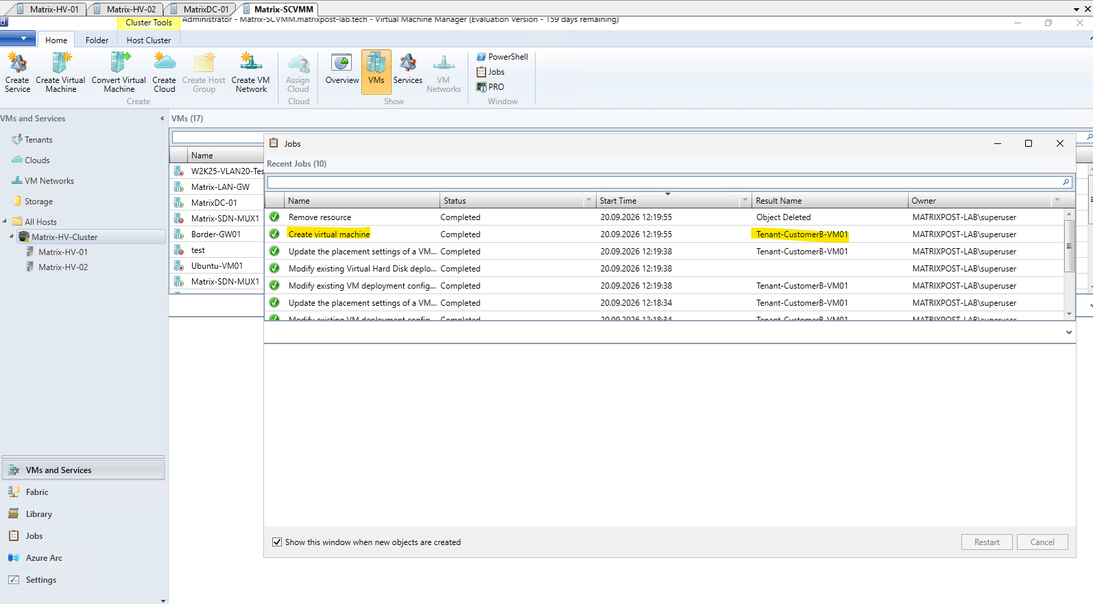
The deployment of our first Customer B workload, Tenant-CustomerB-VM01, completes successfully in SCVMM.
As with our previous tenant VMs, we initially deploy it without connecting its network adapter to the HNV tenant network; we will perform that association through Windows Admin Center next.
Connecting the Customer B VM to the HNV Virtual Network Using Windows Admin Center
As in Part 2, we will use Windows Admin Center to connect the VM network adapter to the HNV virtual network. This time, however, we select our newly created Tenant-CustomerB network and Tenant-CustomerB-Subnet, ensuring that the workload is placed in the second isolated tenant network despite its overlapping Customer Address space.
Connecting the VM Network Adapter
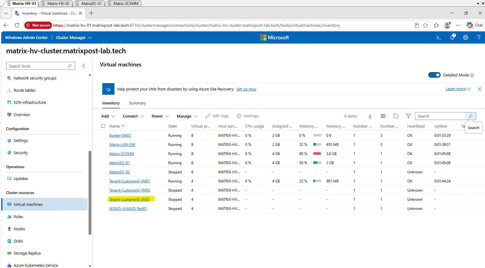
To connect the network adapter of Tenant-CustomerB-VM01 to our newly created HNV virtual network, navigate to Cluster resources → Virtual machines in Windows Admin Center and select our new tenant VM, Tenant-CustomerB-VM01.
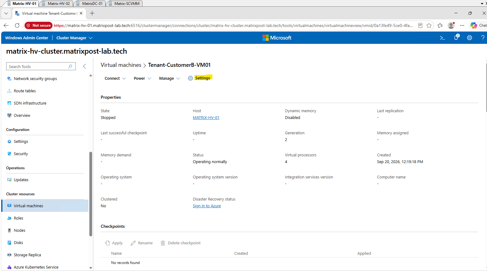
With the Tenant-CustomerB-VM01 details open, click Settings to access the virtual machine configuration.
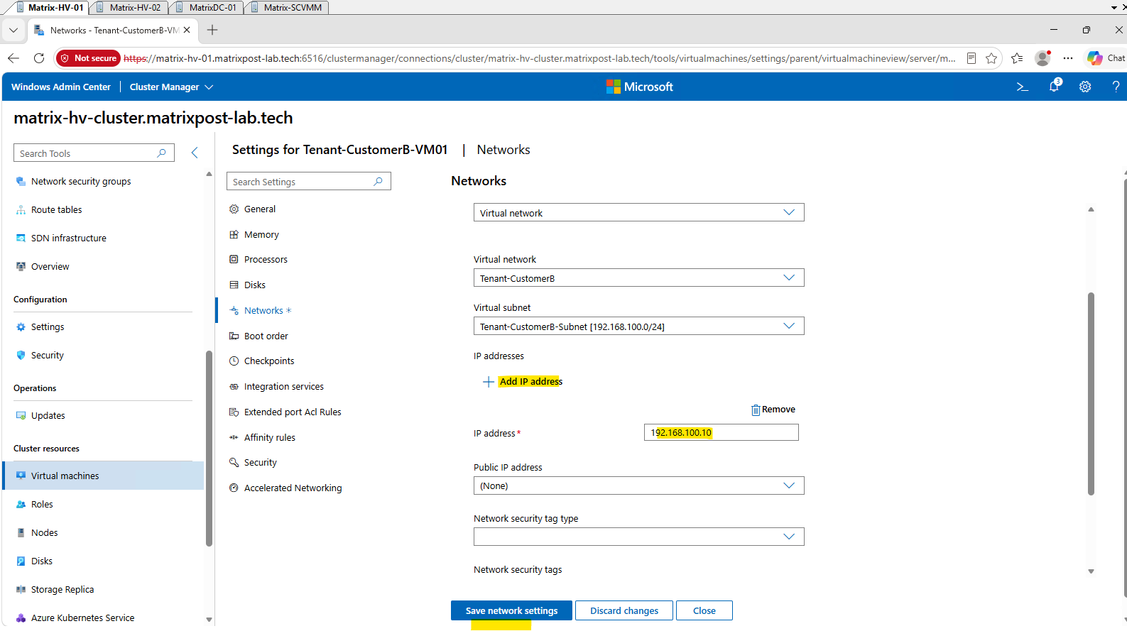
In the VM settings, select Networks and connect the network adapter to the vSwitch-VM virtual switch.
This is the SDN-enabled Hyper-V virtual switch that provides the underlying connectivity required before the adapter can be associated with an HNV virtual network.
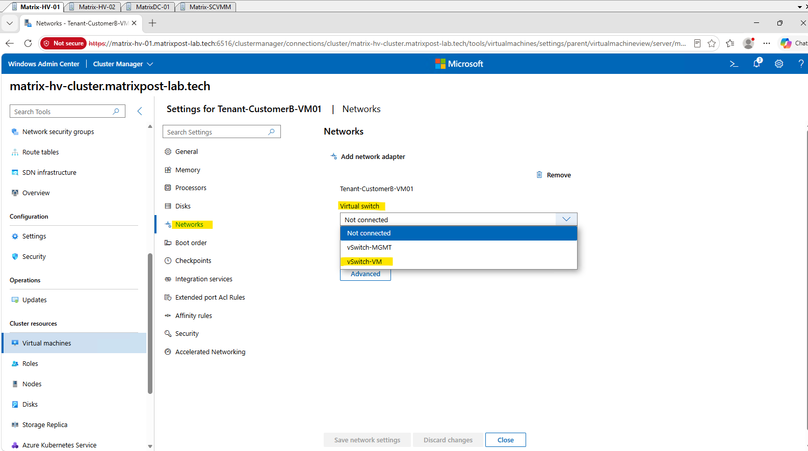
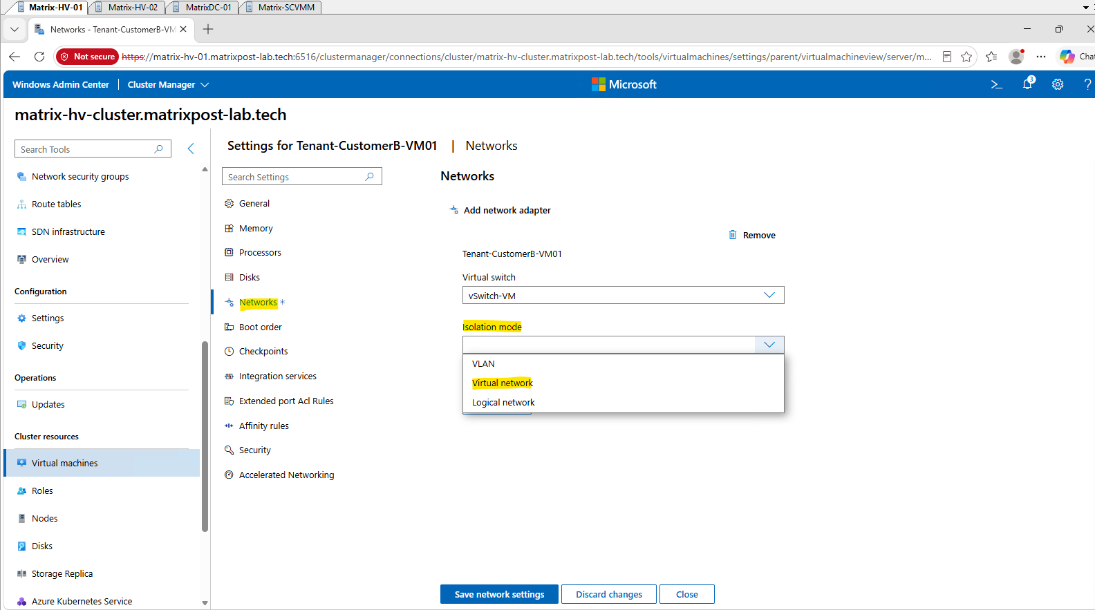
Once vSwitch-VM is selected, Windows Admin Center automatically exposes the additional Isolation mode options. Select Virtual network to configure the VM network adapter for HNV-based network virtualization instead of traditional VLAN isolation or a logical network.
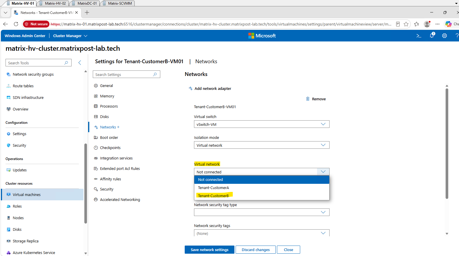
After selecting Virtual network as the isolation mode, Windows Admin Center displays the HNV virtual networks available through the Network Controller. Select our existing Tenant-CustomerB virtual network.
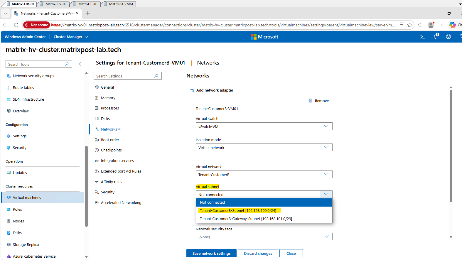
After selecting the Tenant-CustomerB virtual network, select Tenant-CustomerB-Subnet [192.168.100.0/24] as the Virtual subnet.
Although this subnet uses the same
192.168.100.0/24Customer Address space asTenant-CustomerA, it belongs to the separate and isolatedTenant-CustomerBHNV virtual network.
Click Add IP address and assign 192.168.100.10 to our tenant VM.
We leave the optional network security tags and Security Level settings at their defaults, as they are not required for our basic HNV connectivity test.
Finally, click Save network settings to apply the configuration.
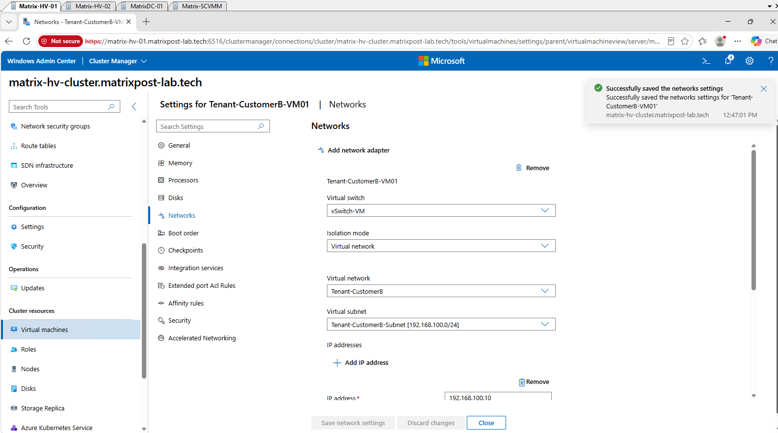
After saving the network settings, the adapter of Tenant-CustomerB-VM01 is connected to Tenant-CustomerB-Subnet [192.168.100.0/24] on vSwitch-VM.
We deliberately assign
192.168.100.10, the same Customer Address already used byTenant-CustomerA-VM01, demonstrating that identical IP addresses can be assigned to workloads in separate HNV virtual networks.
Starting the Customer B Tenant VM and Verifying Provider Address Allocation
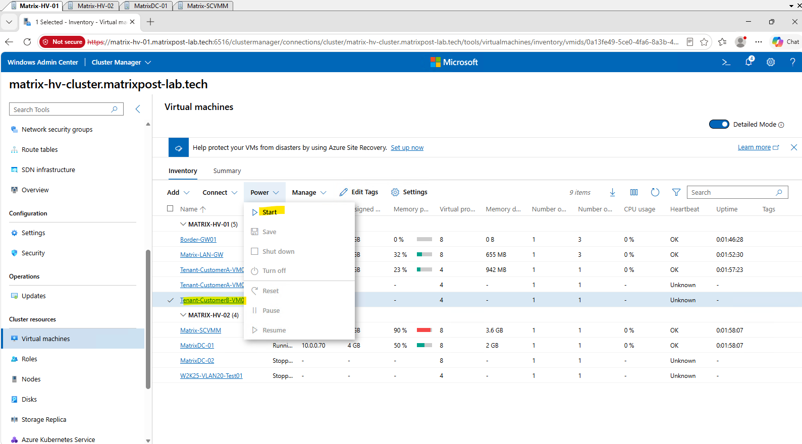
With the network adapter connected to Tenant-CustomerB, we can now start Tenant-CustomerB-VM01. As with our Customer A workloads, starting the first workload on this HNV virtual network allows us to verify how the Network Controller assigns Provider Addresses (PAs) for transporting the new tenant’s traffic across the physical network.
Select Tenant-CustomerB-VM01 and choose Power → Start.
Tenant-CustomerB-VM01 is now running on MATRIX-HV-01 and Windows is starting.
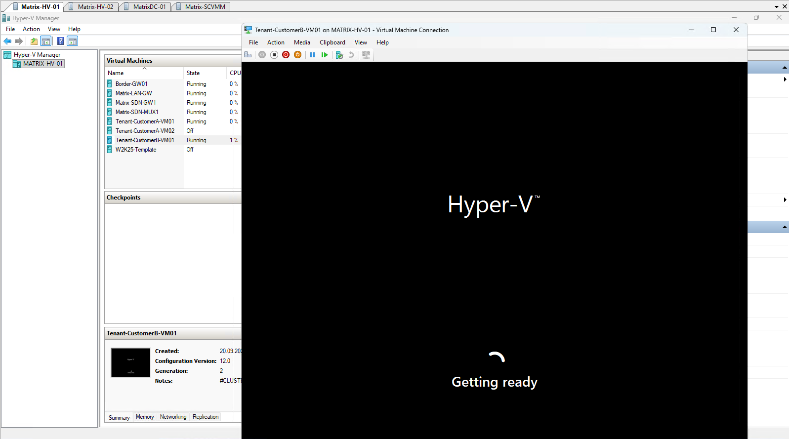
Since the VM was deployed from our Sysprep-prepared Windows Server template, Windows starts with the initial Out-of-Box Experience (OOBE) to complete the operating system setup.
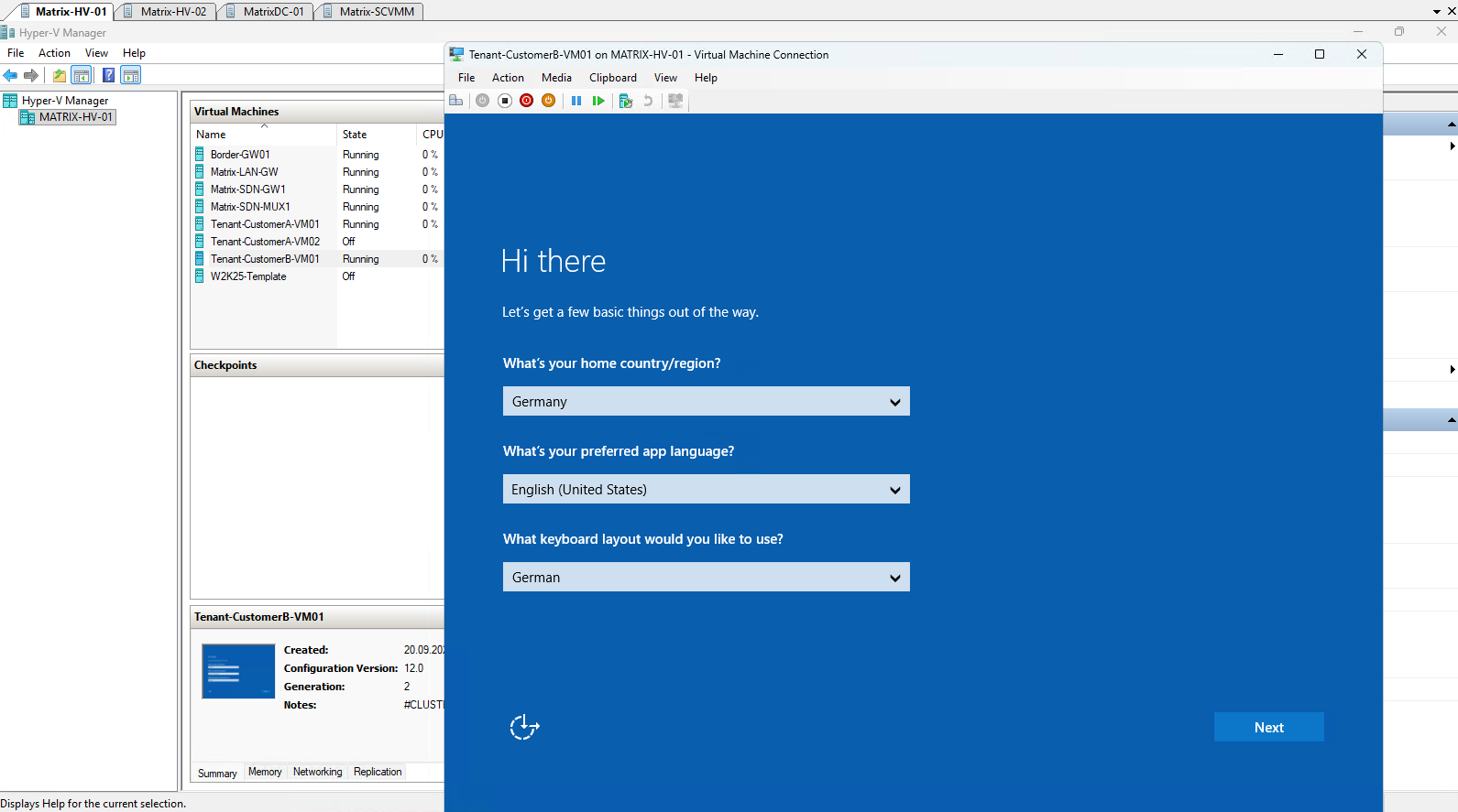
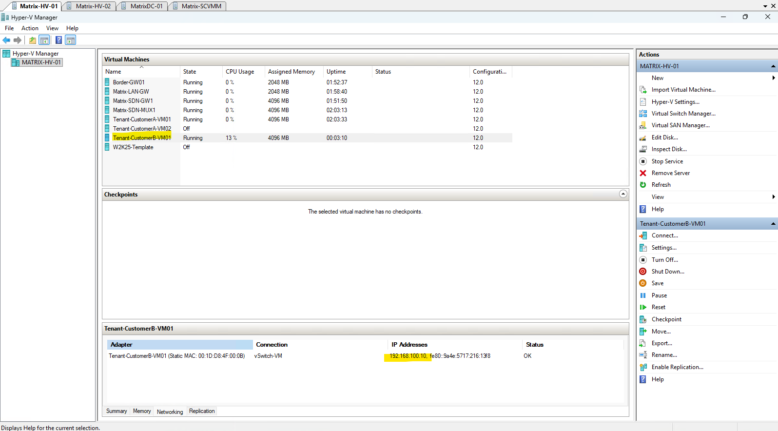
After completing the initial Windows setup, Hyper-V Manager shows
192.168.100.20for the network adapter of Tenant-CustomerB-VM01, confirming the tenant IP address configured through Windows Admin Center.
Verifying the Provider Address and CA-to-PA Mapping
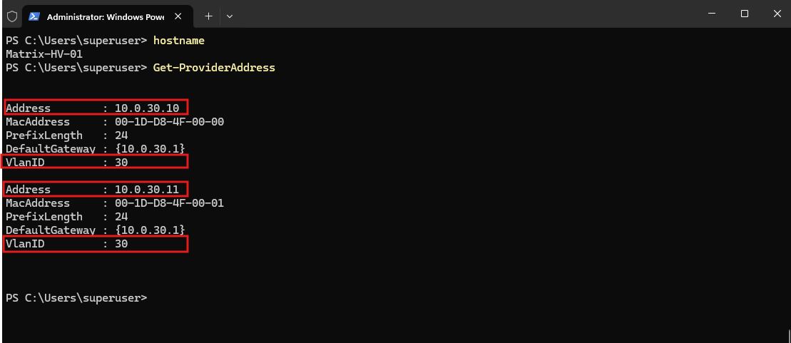
First, we use Get-ProviderAddress on Matrix-HV-01 to display the HNV Provider Addresses (PAs) currently assigned to this Hyper-V host:
The output shows the two Provider Addresses
10.0.30.10and10.0.30.11, both belonging to our VLAN 30 HNVPA underlay network.
Get-ProviderAddress
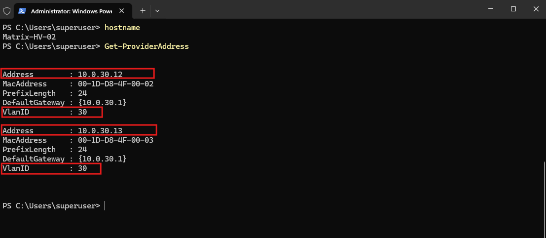
The same on the second Hyper-V Host node Matrix-HV-02:
Across our two Hyper-V hosts, HNV currently uses four Provider Addresses:
10.0.30.10and10.0.30.11onMatrix-HV-01, and10.0.30.12and10.0.30.13onMatrix-HV-02.These Provider Addresses form the underlay transport, allowing the virtualized tenant traffic to be carried across the physical network, where the tenant Customer Addresses cannot be transported directly.
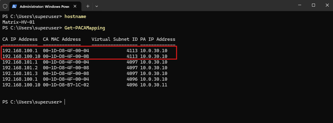
On Matrix-HV-01, Get-PACAMapping now clearly shows the new Tenant-CustomerB workload with CA 192.168.100.10 and its tenant gateway 192.168.100.1, both belonging to Virtual Subnet ID 4113 and mapped to Provider Address 10.0.30.10.
PA/CA mapping represents the relationship between a Provider Address (PA) in the physical underlay network and a Customer Address (CA) in the virtualized HNV tenant network.
This is particularly interesting because
Tenant-CustomerAalso uses192.168.100.10and192.168.100.1, but under Virtual Subnet ID4096, demonstrating how HNV distinguishes overlapping tenant address spaces while transporting them over the same PA underlay.The tenant default gateway
192.168.100.1is provided automatically by the SDN/HNV virtual network, similar to the software-defined default gateway of an Azure Virtual Network subnet, and does not correspond to a physical router interface.
Get-PACAMapping
The Wireshark capture from Part 2 shows the VXLAN header with VNI 4096, identifying the encapsulated traffic as belonging to Tenant-CustomerA-Subnet.
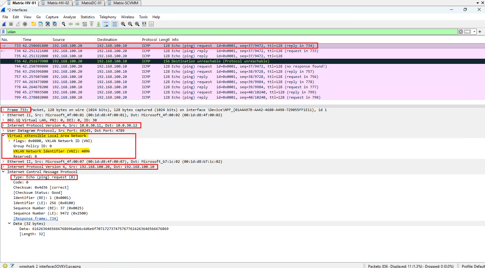
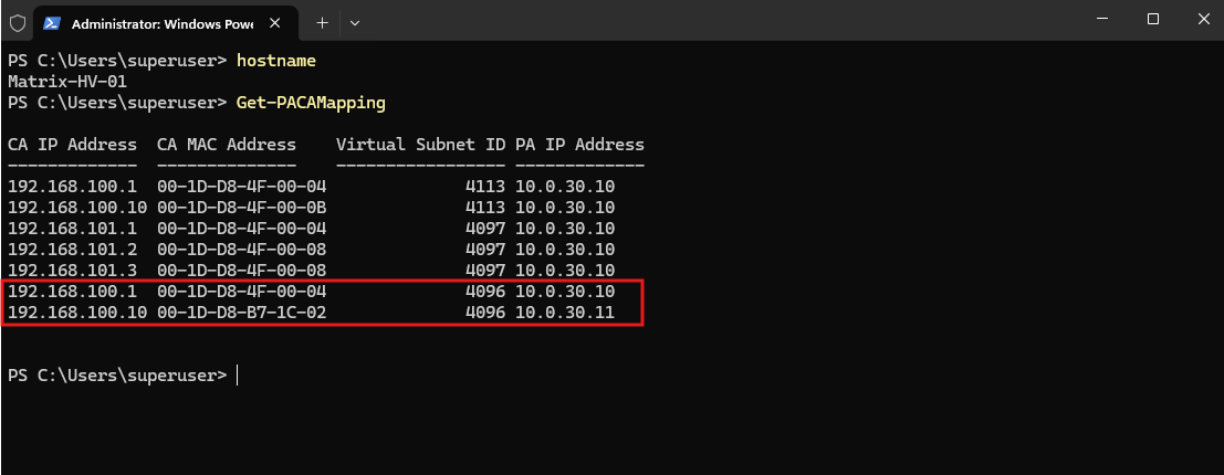
The same identifier (
id 4096) appears as the Virtual Subnet ID inGet-PACAMapping, directly linking the HNV mapping information to the VNI carried on the physical
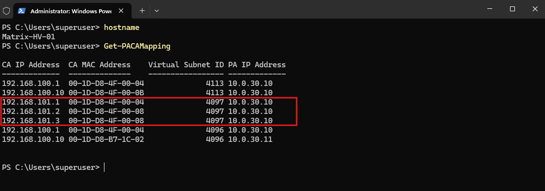
The three entries with Virtual Subnet ID 4097 belong to Tenant-CustomerA-Gateway-Subnet (192.168.101.0/29), which provides the HNV overlay network used by the SDN Virtual Gateway to connect the tenant network toward our external pfSense router.
The gateway subnet therefore has its own VNI
4097, separate from the Customer-A workload subnet using VNI4096.
Limitations When Routing Overlapping Tenant Networks Externally
While HNV allows both tenants to use the same IP address space independently inside the SDN fabric, extending these overlapping networks to a conventional external router introduces an additional challenge. Our pfSense router uses a single routing domain and therefore cannot maintain separate routes for the identical 192.168.100.0/24 tenant prefixes.
Although pfSense provides stateful routing mechanisms such as reply-to, these do not provide the independent routing tables required for general routing between overlapping tenant networks.
A possible workaround would be to deploy a dedicated pfSense appliance for each tenant, thereby giving every tenant its own routing instance. However, this quickly becomes inefficient and defeats much of the purpose of a shared, software-defined multitenant infrastructure.
In Part 5, we will address this limitation by extending the tenant separation beyond the Microsoft SDN fabric using Virtual Routing and Forwarding (VRF).
However, VRF-based routing alone does not solve another challenge associated with overlapping tenant networks: connection tracking and NAT for identical connection tuples. If two tenants use the same source IP address and establish connections with identical five-tuples, a shared Linux connection-tracking table cannot reliably distinguish these sessions, potentially resulting in connection conflicts or incorrect return routing.
In Part 3 of my VMware NSX series, I will address this limitation by implementing dedicated Linux conntrack zones and tenant-specific NAT port ranges, allowing even completely identical TCP five-tuples from different tenants to coexist through a shared WAN interface.
Many enterprise WAN routers and firewall appliances from vendors such as Juniper, Cisco, Fortinet and Check Point address these challenges through vendor-specific features for tenant isolation, virtual routing instances, stateful connection tracking, and NAT.
In Part 4 of my VMware NSX series, we will list the corresponding proprietary technologies and features offered by these platforms.
Links
New-NetworkControllerLogicalSubnet
https://learn.microsoft.com/en-us/powershell/module/networkcontroller/new-networkcontrollerlogicalsubnetAdd a virtual gateway to a tenant virtual network
https://learn.microsoft.com/en-us/windows-server/networking/sdn/manage/add-a-virtual-gateway-to-a-tenant-virtual-networkCreate a VM and connect to a tenant virtual network or VLAN
https://learn.microsoft.com/en-us/windows-server/networking/sdn/manage/create-a-tenant-vmOutbound NAT
https://docs.netgate.com/pfsense/en/latest/nat/outbound.html