Windows Server Software Defined Networking (SDN) and Hyper-V Network Virtualization (HNV) – Part 6: Connecting Overlapping Tenant Networks with Site-to-Site VPNs
In Part 5, we extended our overlapping HNV tenant networks beyond the Microsoft SDN fabric by using Linux VRFs (Virtual Routing and Forwarding) on an Ubuntu router. This allowed both tenants to use their identical 192.168.100.0/24 address spaces while maintaining separate routing contexts and sharing the same Internet connection.
In this sixth part, we will extend this design even further by providing Site-to-Site (S2S) VPN connectivity for each tenant. Two separate Azure Virtual Networks (VNets) will each use a pfSense firewall as an IPsec VPN endpoint, with both VPN tunnels terminating on the shared WAN interface of our Ubuntu router.
The challenge is that both VPN connections ultimately lead to tenant networks using the same 192.168.100.0/24 address space. We therefore need to ensure that traffic arriving through each VPN tunnel is associated with the correct VRF and tenant routing context, allowing identical destination prefixes to coexist without ambiguity.
By the end of this article, two independent Azure VNets will be able to communicate through separate S2S VPN tunnels with their respective HNV tenant networks, while the overlapping tenant address spaces remain completely isolated from each other.
Setting Up the Azure Tenant Networks
For this lab, we will use two separate Azure Virtual Networks (VNets), with each VNet representing the external network of one of our HNV tenants.
Each VNet contains a pfSense firewall that acts as the IPsec endpoint for a dedicated Site-to-Site VPN connection to our on-premises Ubuntu router.
The Azure networks use the following non-overlapping address spaces:
| HNV Tenant | Azure VNet | VNet Address Space | Workload Subnet |
|---|---|---|---|
| Tenant-CustomerA | VNet-TenantA | 10.100.0.0/16 | 10.100.10.0/24 |
| Tenant-CustomerB | VNet-TenantB | 10.200.0.0/16 | 10.200.10.0/24 |
The deployment and basic configuration of pfSense in Azure is outside the scope of this article. I have already covered this process in my separate article below.
For more details about building Site-to-Site IPsec VPNs with pfSense in Azure, including the required Azure NSG rules and routing configuration, see my previous article.
When creating the workload subnets, Private subnet (no default outbound access) is enabled by default now. Azure no longer provides implicit default outbound Internet access for new private subnets, so outbound connectivity must be provided explicitly.
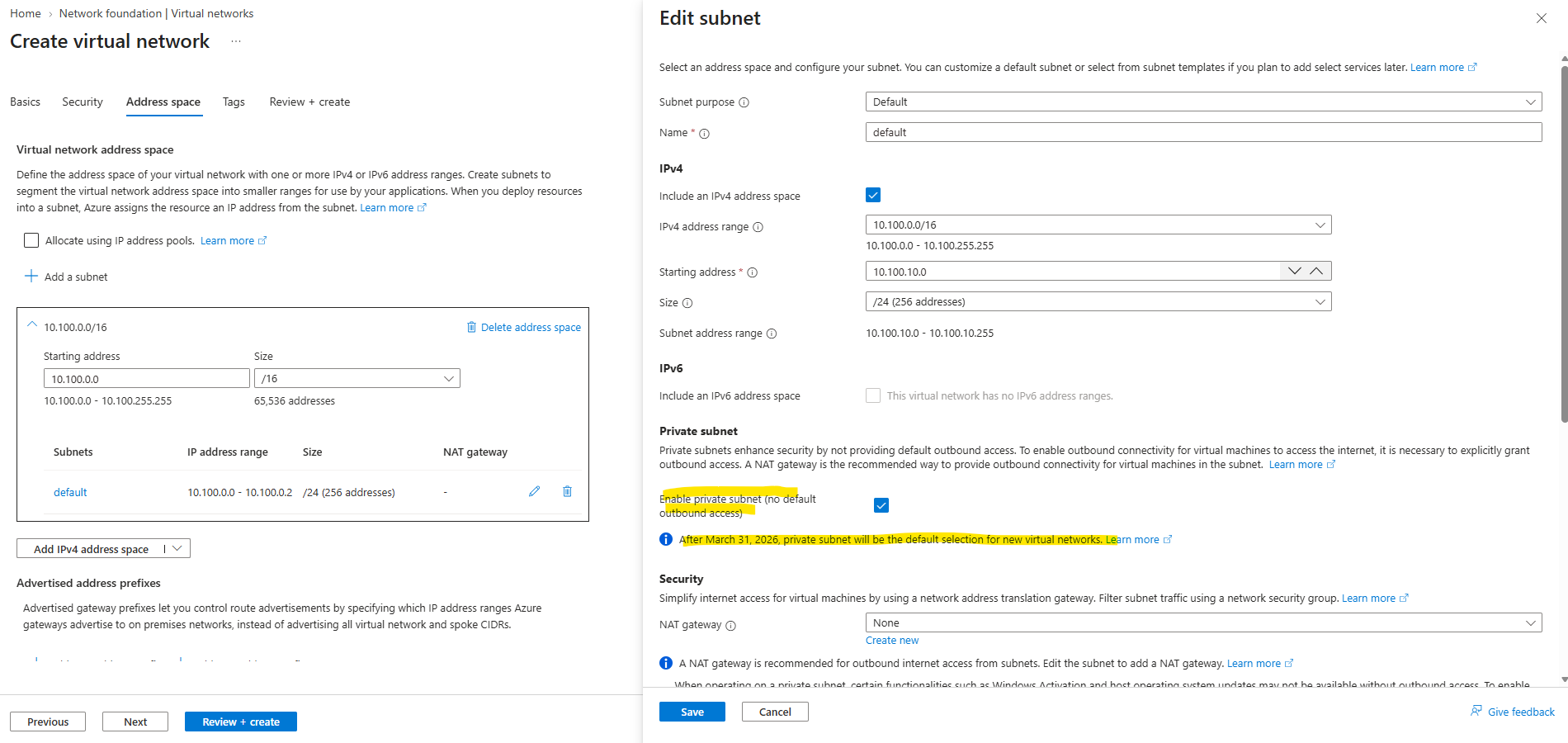
I covered the background and the available options in my following article:
In production environments, Azure workloads are typically separated into spoke VNets, while shared connectivity services such as firewalls and VPN gateways are centralized in a hub VNet. I covered such a design in detail in my following article:
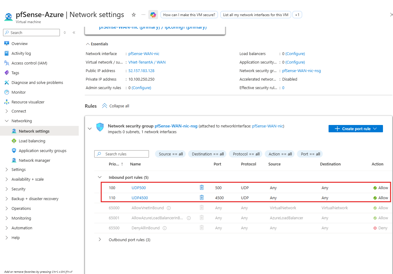
After deploying the pfSense VM, I had not yet assigned a Network Security Group (NSG) to its WAN interface, so unsolicited inbound traffic from the Internet was not permitted.
We therefore need to attach an NSG and explicitly allow UDP 500 (IKE) and UDP 4500 (IPsec NAT-T) for the Site-to-Site VPN.
Azure Standard public IP addresses are secure by default, meaning inbound Internet traffic is blocked unless it is explicitly permitted through a Network Security Group (NSG).
Note: Allowing UDP ports
500and4500fromAnyis used here only for simplicity in my lab environment. In a production environment, these rules should normally be restricted to the public IP address of the remote VPN peer. Because Azure NSG rules cannot use an arbitrary FQDN/Dynamic DNS hostname such asmatrixpost.ddns.netas their source, this is not practical in my lab where the on-premises public IP address changes dynamically.
For this lab, however, we deliberately keep the Azure topology simple and use only a single VNet per tenant, which effectively represents the hub network and contains both the pfSense VPN appliance and our test workload.
This allows us to focus on the S2S VPN and routing between Azure and the overlapping HNV tenant networks rather than on the Azure hub-spoke architecture itself.
In the following sections, we will therefore focus only on the configuration required to establish the two IPsec tunnels and correctly route each Azure VNet to its corresponding overlapping 192.168.100.0/24 HNV tenant network.
Configuring the IPsec VTI on the Ubuntu Router
With the Azure-side pfSense configuration in place, we can now configure the corresponding route-based IPsec tunnel on the Ubuntu router. The tunnel for Tenant-CustomerA will terminate on the Ubuntu router’s WAN interface and use a dedicated VTI network (169.254.100.0/30), which we will subsequently integrate into the existing Tenant-CustomerA VRF routing context.
For the IPsec implementation on Ubuntu, we will use strongSwan and configure the IKEv2 and ESP parameters to match the settings configured on pfSense-TenantA.matrixpost-lab.tech.
Note: pfSense also uses the open-source strongSwan project as its underlying IPsec implementation. Therefore, although the pfSense side is configured through its web interface, both VPN endpoints in this lab ultimately use strongSwan for the IKE and IPsec negotiation.
Other VPN appliances from vendors such as Cisco, Juniper, Fortinet, and Check Point use their own vendor-specific IPsec/IKE implementations rather than strongSwan. However, they interoperate through the standardized IKE/IPsec protocols, provided the cryptographic proposals and tunnel parameters match on both endpoints.
First, install the required strongSwan packages on the Ubuntu router. The strongswan package provides the IPsec/IKE implementation and the tools required to establish and manage the VPN tunnels.
sudo apt update
sudo apt install strongswan -y
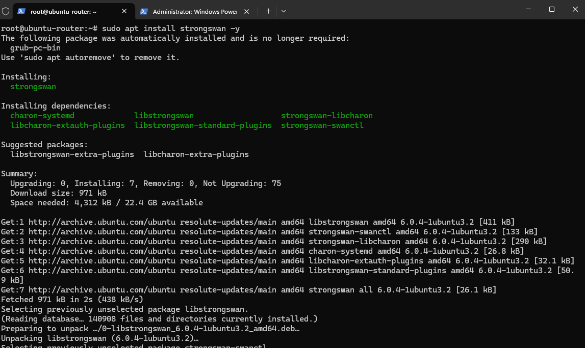
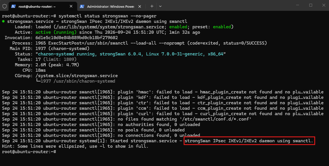
Verify that the strongSwan service is running.
On this Ubuntu system, strongSwan uses the modern
swanctlconfiguration backend withcharon-systemdas the IKE daemon.
systemctl status strongswan --no-pager
Configuring the Tenant-CustomerA IKEv2 Connection
The first strongSwan connection represents the IPsec tunnel to pfSense-TenantA in Azure. The IKE and ESP proposals are configured to match the corresponding pfSense Phase 1 and Phase 2 settings.
Create /etc/swanctl/conf.d/tenant-customera.conf:
connections {
    tenant-customera {
        version = 2
        local_addrs = %any
        remote_addrs = 52.157.183.128

        proposals = aes256-sha256-prfsha256-modp2048s256

        local {
            auth = psk
            id = matrixpost.ddns.net
        }

        remote {
            auth = psk
            id = 52.157.183.128
        }

        children {
            tenant-customera {
                mode = tunnel

                local_ts = 0.0.0.0/0
                remote_ts = 0.0.0.0/0

                esp_proposals = aes256-sha256-modp2048s256

                start_action = none
                dpd_action = restart
            }
        }

        dpd_delay = 10s
        rekey_time = 25920s
        over_time = 2880s
    }
}

secrets {
    ike-tenant-customera {
        id-1 = matrixpost.ddns.net
        id-2 = 52.157.183.128
        secret = "YOUR-PRESHARED-KEY"
    }
}
The local and remote authentication blocks define the identities used for IKEv2 PSK authentication. The Ubuntu router identifies itself as
matrixpost.ddns.net, while the Azure pfSense endpoint is identified by its public IP address52.157.183.128, matching the identities configured on the pfSense side.
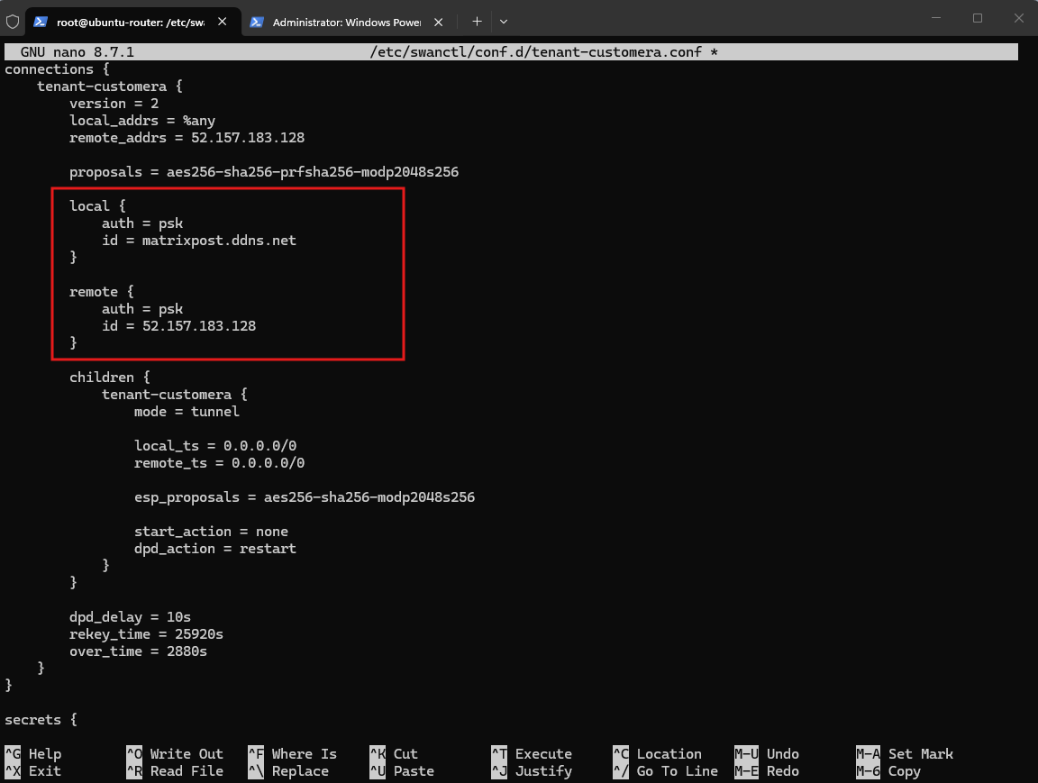
A couple of deliberate choices here. modp2048s256 is strongSwan’s keyword for the RFC 5114 2048-bit MODP group with 256-bit subgroup, i.e. pfSense’s DH Group 24. The explicit prfsha256 completes the IKE proposal corresponding to AES-256/SHA256/Group 24. strongSwan proposal components are specified as dash-separated algorithm keywords.
For now, local_ts and remote_ts are both 0.0.0.0/0 because this is a route-based tunnel; actual tenant forwarding will later be controlled by the VTI/XFRM interface and the Customer A VRF rather than by policy-based subnet selectors.
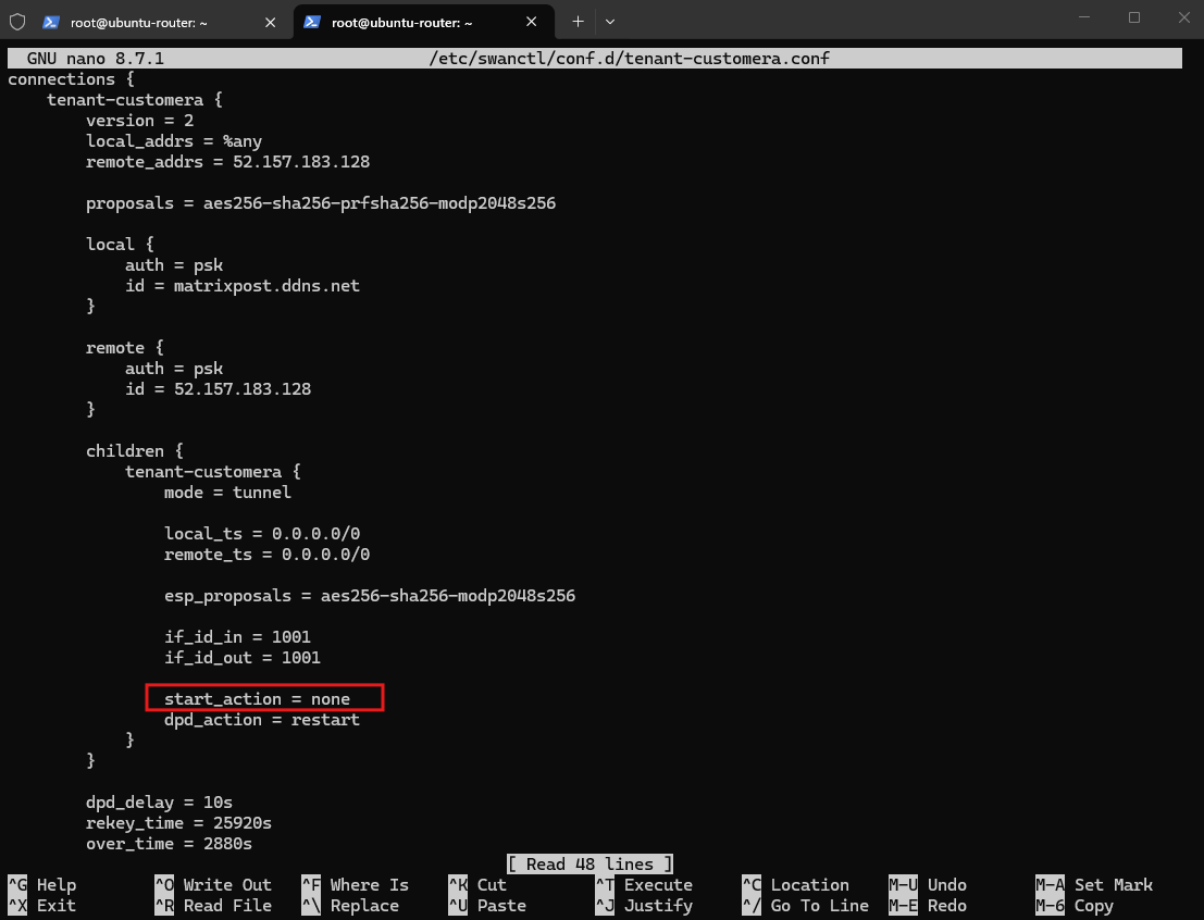
Currently,
start_action = noneprevents strongSwan from automatically initiating the IPsec tunnel when the configuration is loaded. To automatically establish the tunnel after a service or system restart, change this setting tostart_action = start.
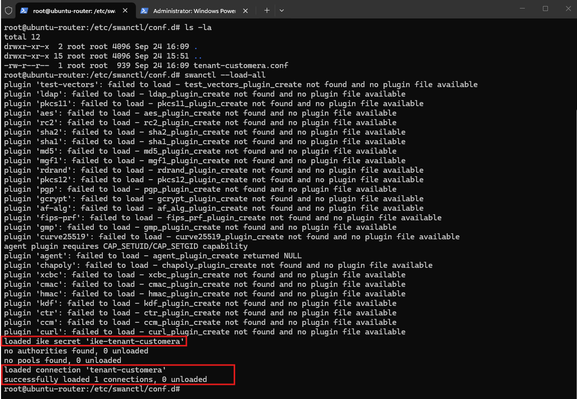
Now we first validate/load the configuration. Load the new strongSwan configuration using the following command:
The output confirms that both the IKE pre-shared key and the
tenant-customeraconnection were loaded successfully.
swanctl --load-all
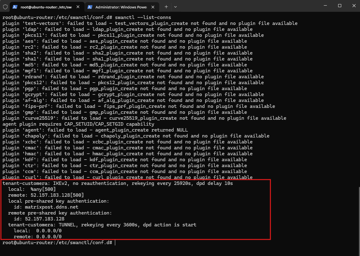
Using swanctl --list-conns, we can verify the loaded Tenant-CustomerA configuration.
strongSwan shows the expected IKEv2 identities, Azure pfSense peer address, and the
0.0.0.0/0traffic selectors used for our route-based IPsec tunnel.
swanctl --list-conns
Now we need the route-based interface. For this lab I’d use a modern XFRM interface rather than the older Linux VTI mechanism. It interoperates with pfSense’s route-based/VTI Phase 2, while strongSwan explicitly supports associating CHILD_SAs with XFRM interfaces via if_id_in/if_id_out
Creating the Tenant-CustomerA XFRM Interface
Next, we create a dedicated XFRM interface for the Tenant-CustomerA IPsec tunnel. By attaching (also referred to as enslaving) this interface to the existing vrf-tenant1 VRF, decrypted VPN traffic is placed directly into routing table 1001, preserving the isolated routing context established in Part 5.
XFRM (transform) is the Linux kernel framework used to implement IPsec packet processing, including the security policies and security associations that determine how packets are encrypted and decrypted.
An XFRM interface provides a virtual network interface for this IPsec processing, allowing the encrypted tunnel to participate in normal Linux routing like other network interfaces.
In our design, the XFRM interface is the Linux-side route-based IPsec tunnel interface, corresponding conceptually to the VTI (Virtual Tunnel Interface) configured on pfSense, although Linux XFRM interfaces and traditional VTI interfaces use different kernel mechanisms.
A traditional Linux VTI binds the virtual tunnel interface more directly to an IPsec tunnel and its endpoints/policies. An XFRM interface instead uses an interface ID (
if_id) to associate traffic with IPsec policies/SAs, making it more flexible for route-based IPsec, multiple tunnels, and especially VRF integration like ours.
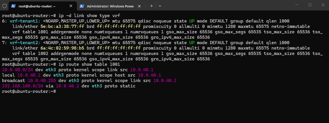
First, we can verify the existing VRF configuration and routing table:
The output confirms that
vrf-tenant1uses routing table 1001, which already contains the route to theTenant-CustomerAHNV network192.168.100.0/24through the SDN gateway at10.0.40.2.
ip -d link show type vrf
ip route show table 1001
We can now create the XFRM interface and attach it to vrf-tenant1:
At this point, the XFRM interface is created dynamically in the running Linux system. Unlike the VRFs configured persistently through Netplan in Part 5, this interface will not survive a reboot. We will make the XFRM interfaces and their associated routes persistent later in this article.
ip link add ipsec-tenant1 type xfrm if_id 1001
ip link set ipsec-tenant1 master vrf-tenant1

Next, we assign the Ubuntu side of the dedicated VTI transit network and bring the interface up:
The following commands assign the Ubuntu-side VTI transit address and bring the XFRM interface up. Like the XFRM interface itself, this configuration modifies only the current runtime network state and must later be made persistent to survive a reboot.
ip addr add 169.254.100.2/30 dev ipsec-tenant1
ip link set ipsec-tenant1 up

The corresponding pfSense endpoint uses 169.254.100.1/30, giving us the following route-based VPN transit network:
pfSense-TenantA     169.254.100.1/30
        |
     IPsec
        |
Ubuntu Router       169.254.100.2/30
        |
   vrf-tenant1
   Table 1001
        |
Tenant-CustomerA
192.168.100.0/24
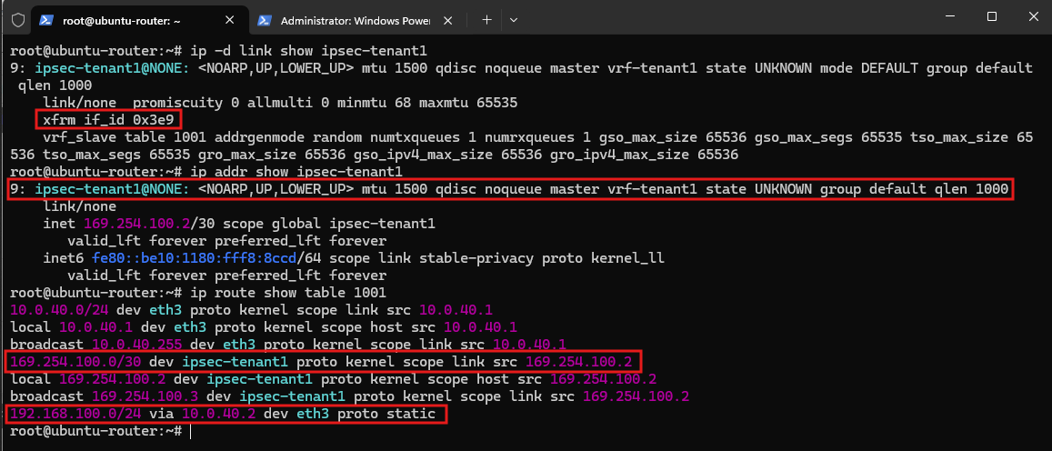
Finally, we verify the new interface and the resulting routes:
The output confirms that
ipsec-tenant1is associated withvrf-tenant1and uses XFRM interface ID1001(0x3e9). The connected169.254.100.0/30VPN transit network has consequently been installed in routing table 1001, alongside the existing route to theTenant-CustomerAHNV network.
ip -d link show ipsec-tenant1
ip addr show ipsec-tenant1
ip route show table 1001
Next we need to bind the strongSwan CHILD_SA to XFRM ID 1001 before establishing the tunnel.
Binding the CHILD_SA to the XFRM Interface
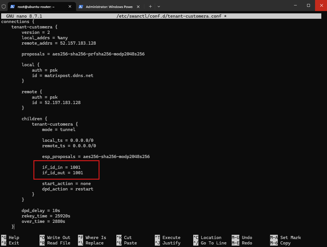
We now bind the strongSwan CHILD_SA to XFRM interface ID 1001 for both directions. This associates the IPsec policies and SAs with ipsec-tenant1, allowing traffic routed through the interface to be processed by the corresponding Tenant-CustomerA IPsec tunnel.
Add these two lines inside the existing children { tenant-customera { ... } } section in our /etc/swanctl/conf.d/tenant-customera.conf file.
if_id_in = 1001
if_id_out = 1001
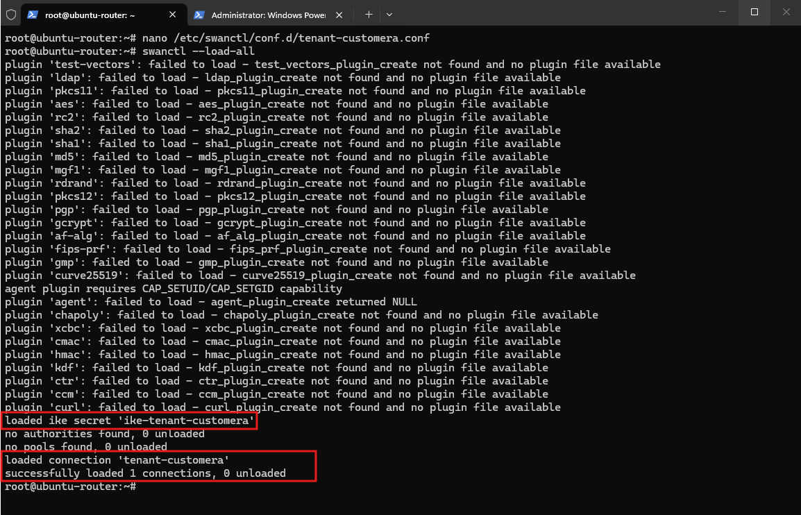
Reload the configuration:
Reload is successful again. The updated CHILD_SA configuration with the XFRM interface IDs has been accepted. The plugin noise can still be ignored.
swanctl --load-all
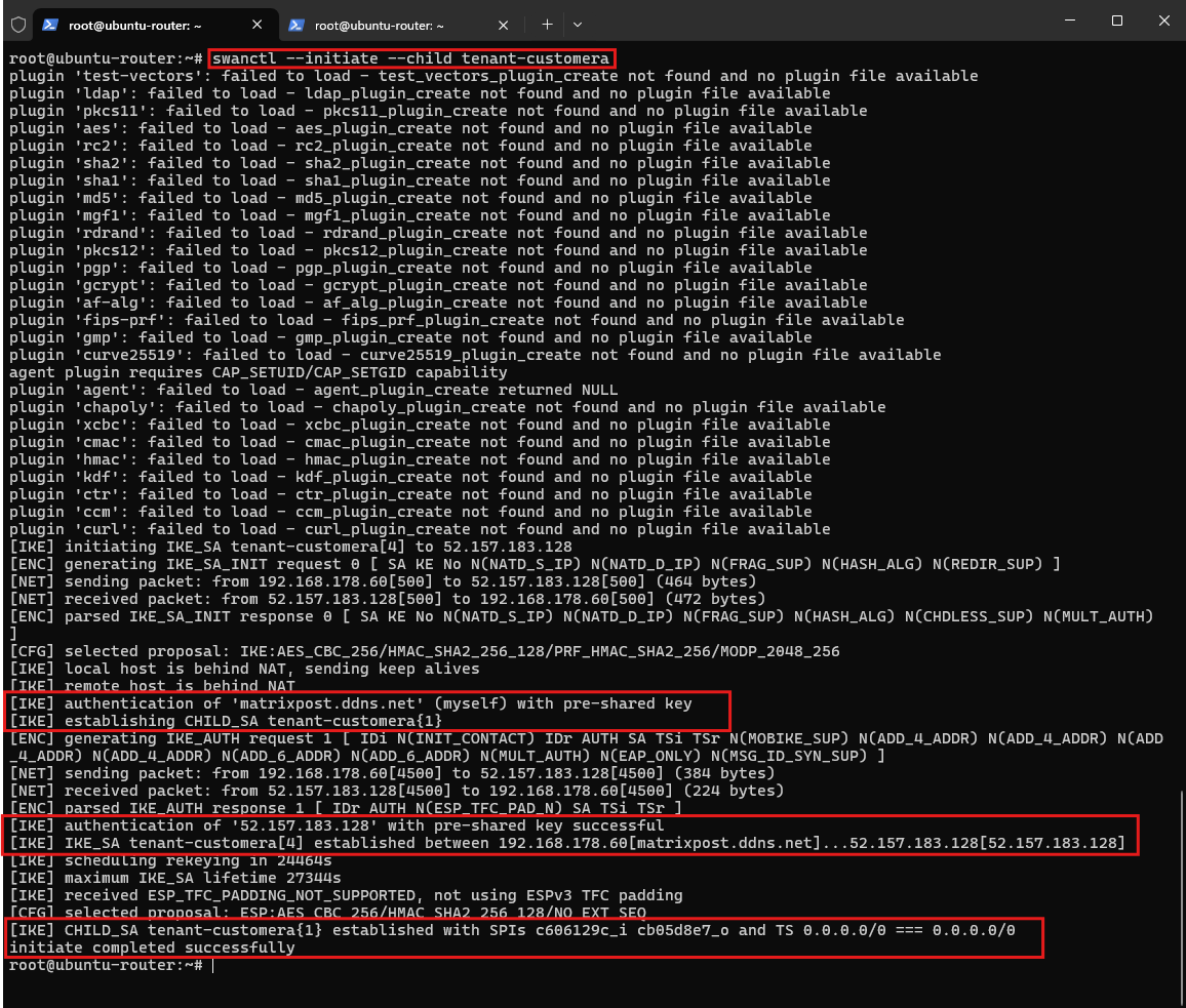
With the strongSwan configuration and XFRM interface in place, we can now initiate the Tenant-CustomerA IPsec connection to pfSense-TenantA. The CHILD_SA is initiated using the following command:
The output confirms that pre-shared key authentication succeeds and the IKEv2
IKE_SAis established betweenmatrixpost.ddns.netand the Azure pfSense endpoint52.157.183.128.Finally, the
tenant-customeraCHILD_SA is successfully established with the route-based0.0.0.0/0traffic selectors in both directions.
swanctl --initiate --child tenant-customera
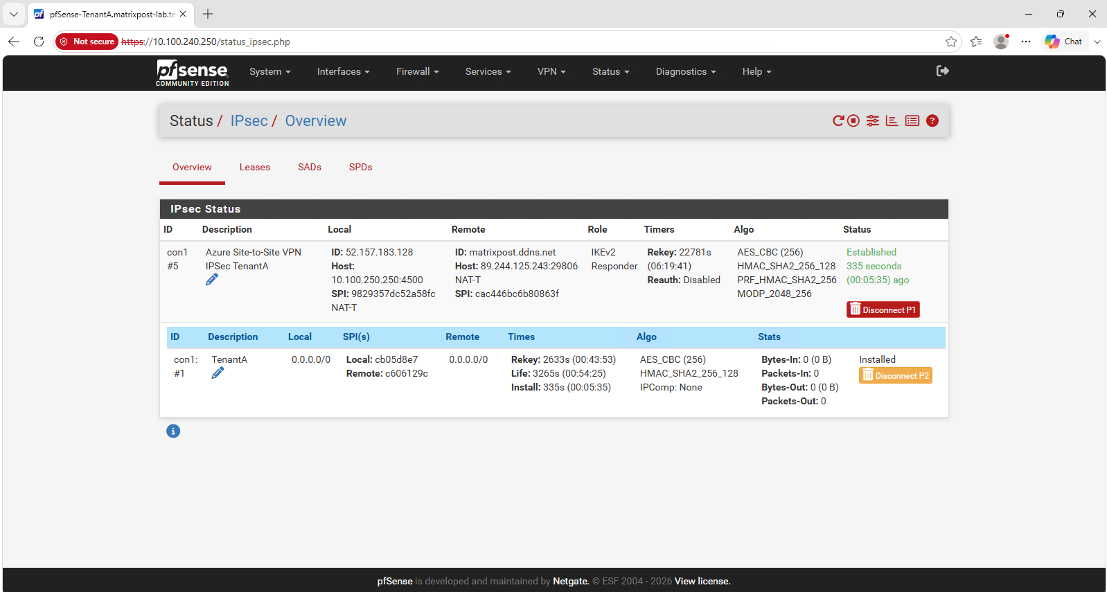
The pfSense IPsec status confirms the same result from the opposite endpoint: the IKEv2 Phase 1 connection is established and the corresponding Phase 2 CHILD_SA is installed. The connection also shows NAT-T, confirming that the IPsec traffic is encapsulated over UDP port
4500.
With the IKE_SA and CHILD_SA successfully established, the IPsec control plane is now working.
However, establishing the tunnel alone does not yet provide connectivity between the Azure and HNV tenant networks. We now need to configure the routing so that traffic follows the intended tenant-specific path:
Azure
VM-TenantA(10.100.240.10) → pfSense (10.100.240.250) → IPsec/XFRM → Ubuntuipsec-tenant1→ VRF table1001→ SDN Gateway (10.0.40.2) → HNVTenant-CustomerA(192.168.100.0/24), with the corresponding return path in the opposite direction.
Configuring the Tenant-CustomerA Routing
The required routing must be configured on both sides of the IPsec connection. We will first configure the on-premises Ubuntu router and then continue with the Azure pfSense router.
Configuring the On-Premises Ubuntu Router
We will start on the Ubuntu router, where routing table 1001 already contains the route toward the HNV Tenant-CustomerA network (192.168.100.0/24).
To complete the routing on this side, we now need to add the corresponding route toward the Azure Tenant A network (10.100.240.0/24) through the ipsec-tenant1 XFRM interface.
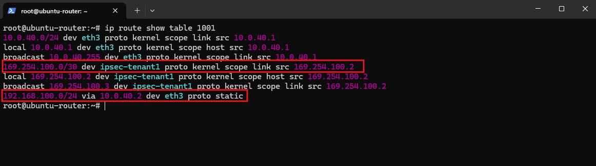
First, let’s display the current contents of routing table 1001 to verify the existing Tenant-CustomerA routes before making any changes.
The table already contains the route to the HNV tenant network
192.168.100.0/24through the SDN Gateway at10.0.40.2, as well as the directly connected XFRM transit network169.254.100.0/30. What is still missing is a route back toward the AzureTenant-CustomerAnetwork.
ip route show table 1001
We add this route through the pfSense VTI address 169.254.100.1 using the ipsec-tenant1 XFRM interface:
This route is added only to the current runtime routing table and will not survive a reboot; we will make it persistent together with the XFRM interface configuration later.
ip route add table 1001 10.100.240.0/24 via 169.254.100.1 dev ipsec-tenant1

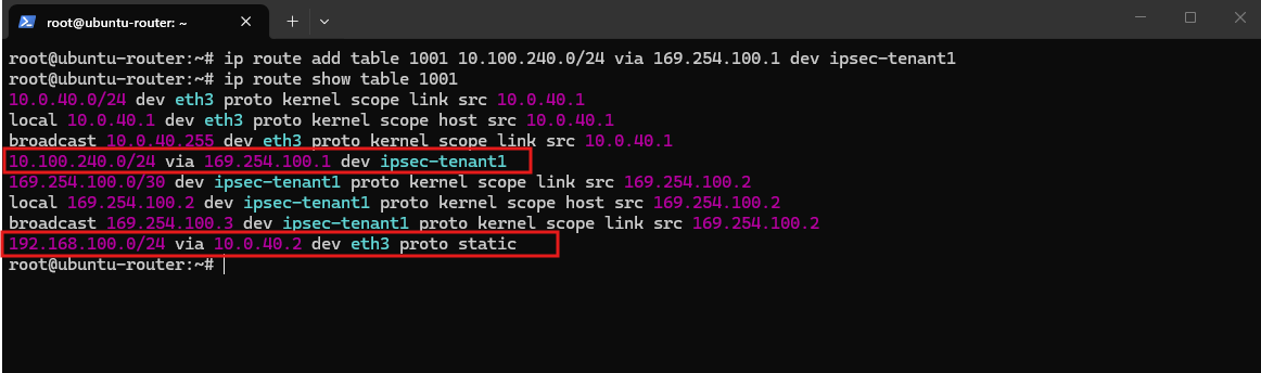
Then verify the updated routing table:
The updated routing table now contains routes for both sides of the Tenant-CustomerA connection: the Azure network
10.100.240.0/24is reached through the pfSense VTI endpoint169.254.100.1viaipsec-tenant1, while the overlapping HNV network192.168.100.0/24remains reachable through the SDN Gateway at10.0.40.2.
ip route show table 1001
Making the Tenant-CustomerA XFRM Configuration Persistent
The XFRM interface, its VRF assignment, transit address, interface state, and Azure route configured above exist only in the current runtime network configuration. To automatically restore this configuration after rebooting the Ubuntu router, we create a small systemd oneshot service.
Create the service:
nano /etc/systemd/system/tenant-xfrm.service
Add the following configuration for Tenant-CustomerA:
[Unit]
Description=Tenant XFRM interfaces and VRF routes
After=network-online.target
Wants=network-online.target

[Service]
Type=oneshot
RemainAfterExit=yes

ExecStart=/usr/sbin/ip link add ipsec-tenant1 type xfrm if_id 1001
ExecStart=/usr/sbin/ip link set ipsec-tenant1 master vrf-tenant1
ExecStart=/usr/sbin/ip addr add 169.254.100.2/30 dev ipsec-tenant1
ExecStart=/usr/sbin/ip link set ipsec-tenant1 up
ExecStart=/usr/sbin/ip route add 10.100.240.0/24 via 169.254.100.1 dev ipsec-tenant1 table 1001

ExecStop=/usr/sbin/ip link del ipsec-tenant1

[Install]
WantedBy=multi-user.target
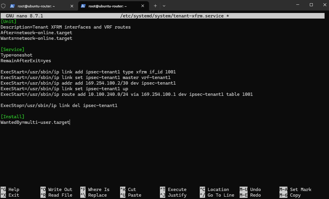
The service recreates ipsec-tenant1, attaches it to vrf-tenant1, assigns the 169.254.100.2/30 transit address, brings the interface up, and restores the route to the Azure Tenant A network in routing table 1001.
Enable the service so that it runs automatically during future system boots:
systemctl daemon-reload
systemctl enable tenant-xfrm.service
Because ipsec-tenant1 is already configured in the running system, we only enable the service at this point and do not start it manually. The service will recreate the configuration after the next reboot.
Configuring the Azure pfSense Router
With the routing on the on-premises Ubuntu router in place, we can now configure the corresponding route on pfSense-TenantA. Traffic destined for the HNV Tenant-CustomerA network (192.168.100.0/24) must be forwarded through the IPsec VTI toward the Ubuntu tunnel endpoint at 169.254.100.2.
The IPsec VTI has already been assigned as the VTI interface under Interfaces → Assignments.
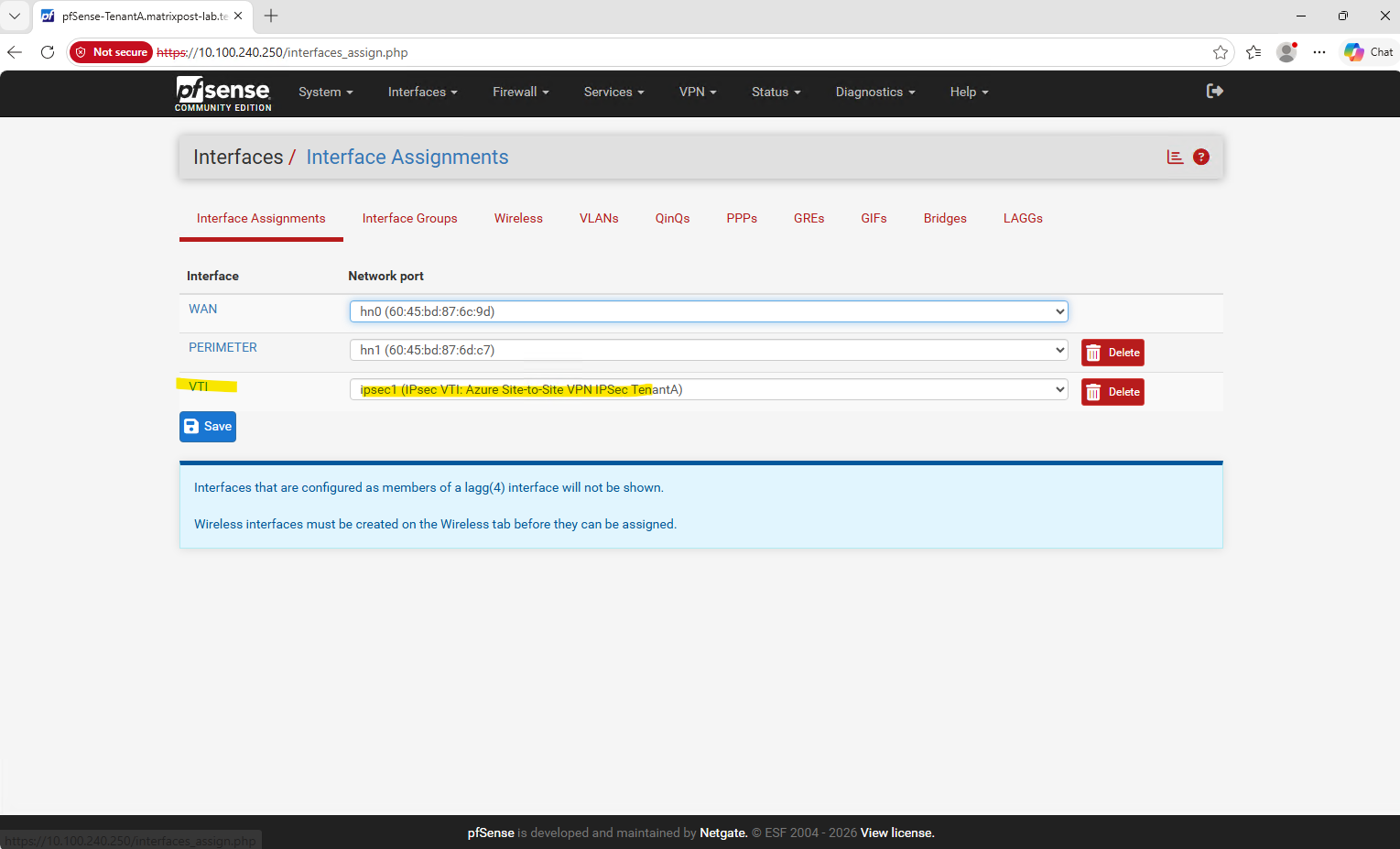
We can therefore use this interface to create a dedicated gateway representing the Ubuntu side of the route-based IPsec tunnel.
Next, we create a dedicated gateway for the remote side of the IPsec VTI under System → Routing → Gateways. This gateway represents the Ubuntu XFRM endpoint 169.254.100.2 and will subsequently be used as the next hop for the HNV tenant network.
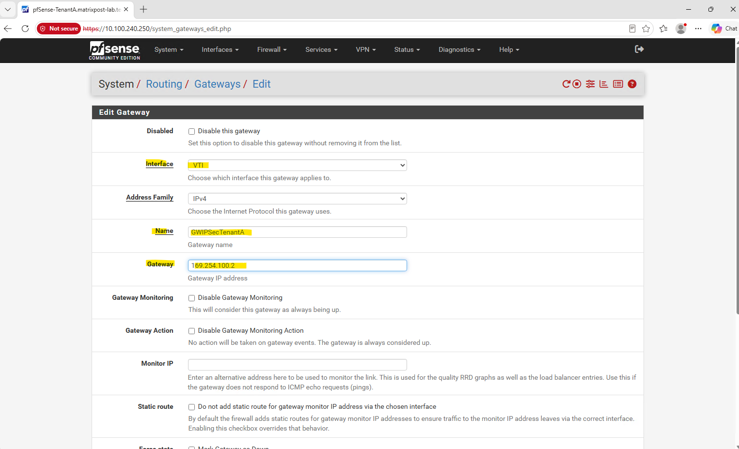
The new
GWIPSecTenantAgateway now represents the Ubuntu side of the IPsec tunnel (169.254.100.2) and is associated with the pfSenseVTIinterface. We can now use this gateway as the next hop for the HNVTenant-CustomerAnetwork.
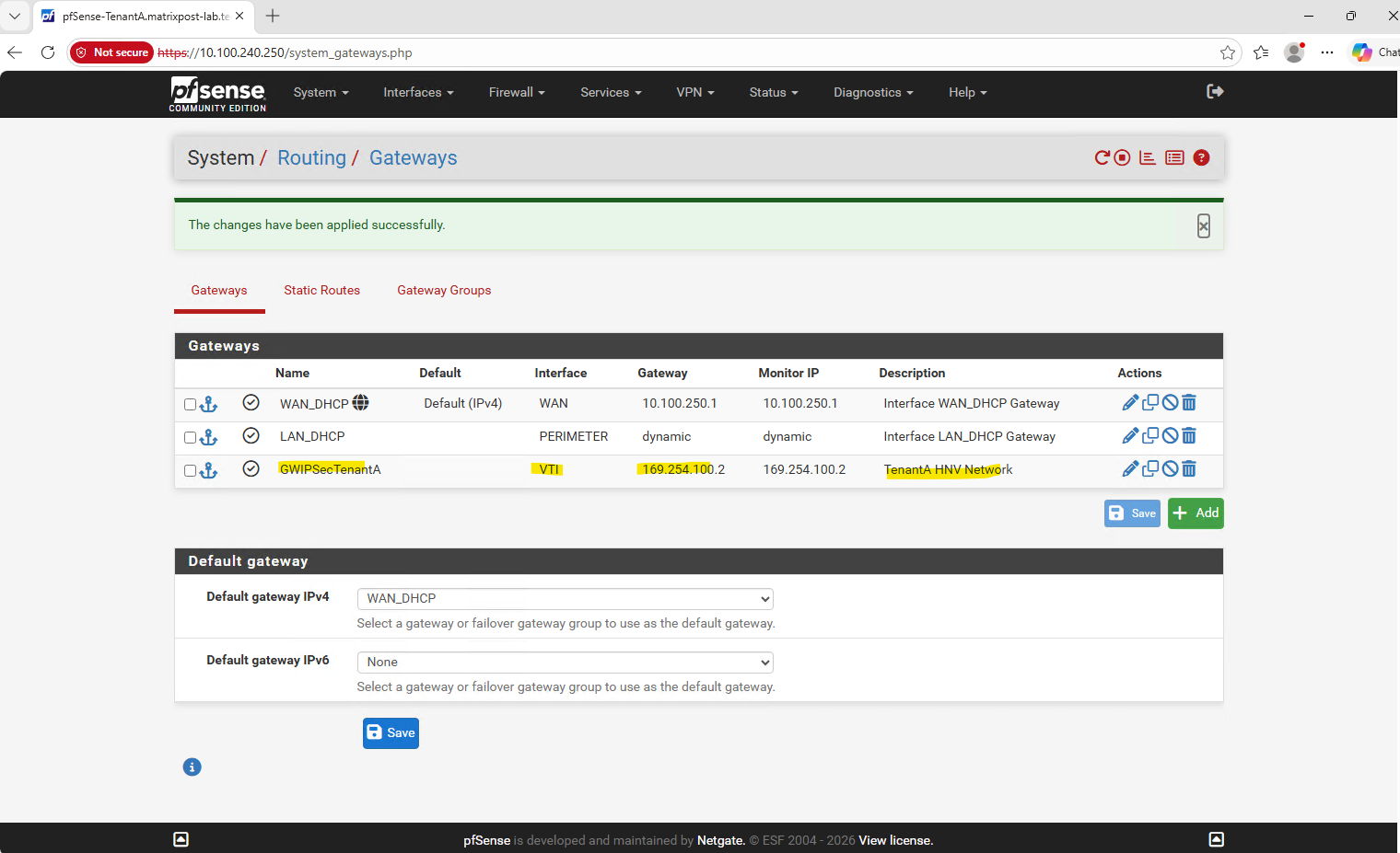
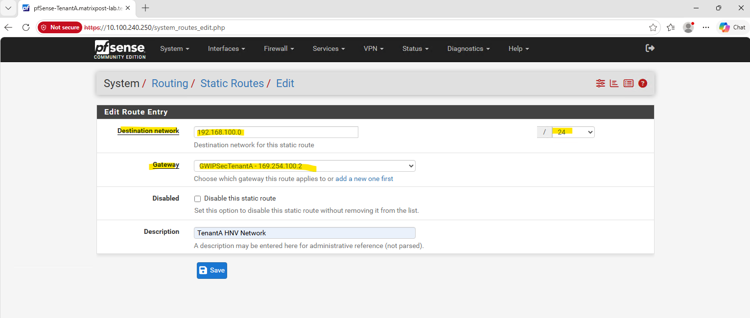
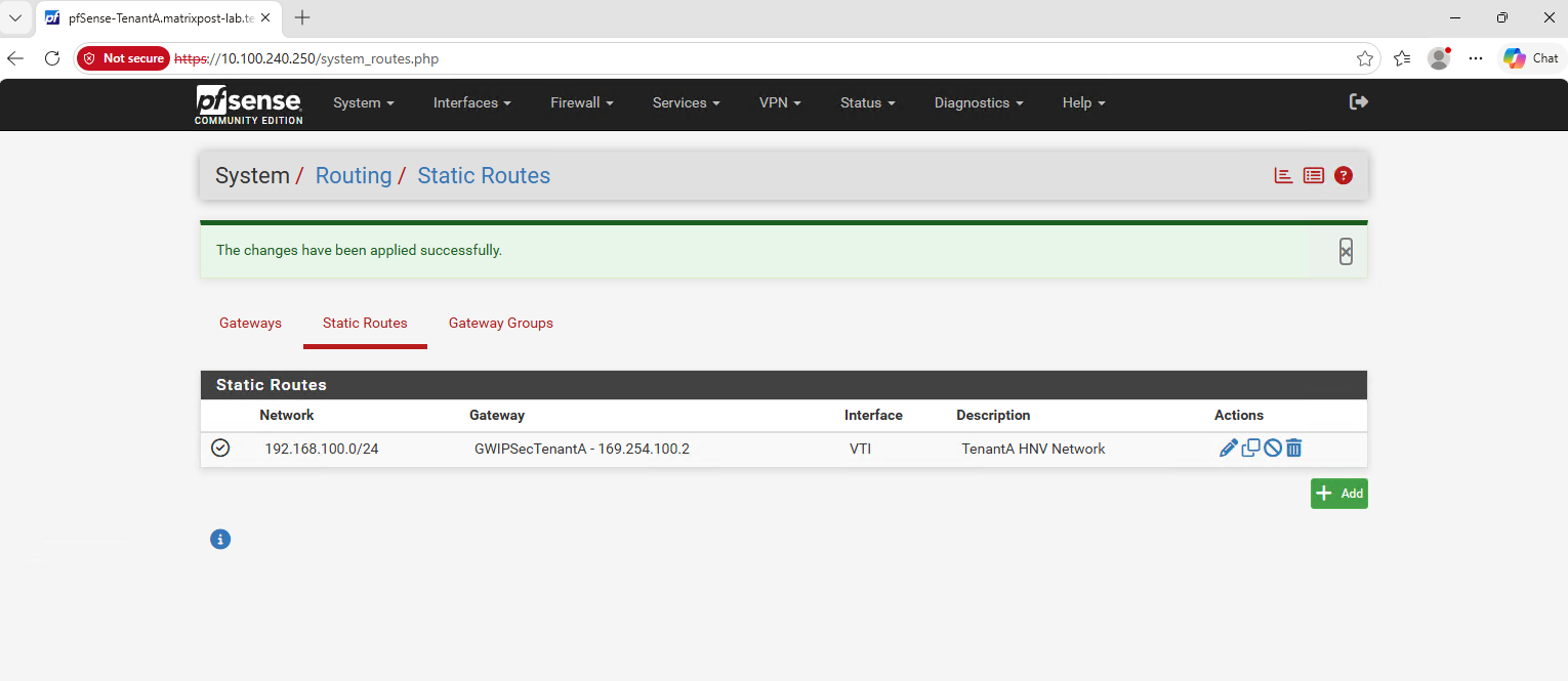
Finally, we add a static route for the HNV Tenant-CustomerA network (192.168.100.0/24) and select GWIPSecTenantA (169.254.100.2) as the gateway. pfSense will therefore forward traffic destined for the HNV tenant network through the VTI and the Tenant-CustomerA IPsec tunnel toward the Ubuntu router.
Go to System → Routing → Static Routes and adding the new route.
Configuring the Azure User-Defined Route
The routing between pfSense and the on-premises Ubuntu router is now configured, but the Azure workload subnet still needs to send traffic for the HNV Tenant-CustomerA network through pfSense.
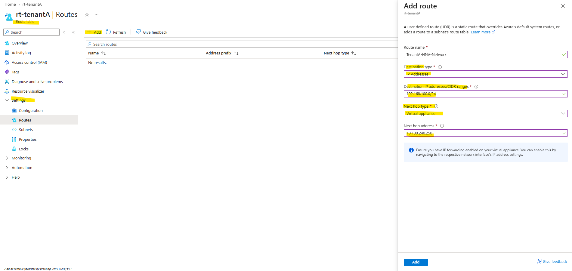
We therefore create an Azure User-Defined Route (UDR) for 192.168.100.0/24, using the pfSense PERIMETER interface 10.100.240.250 as the virtual appliance next hop.
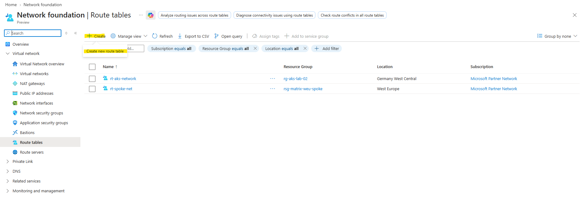
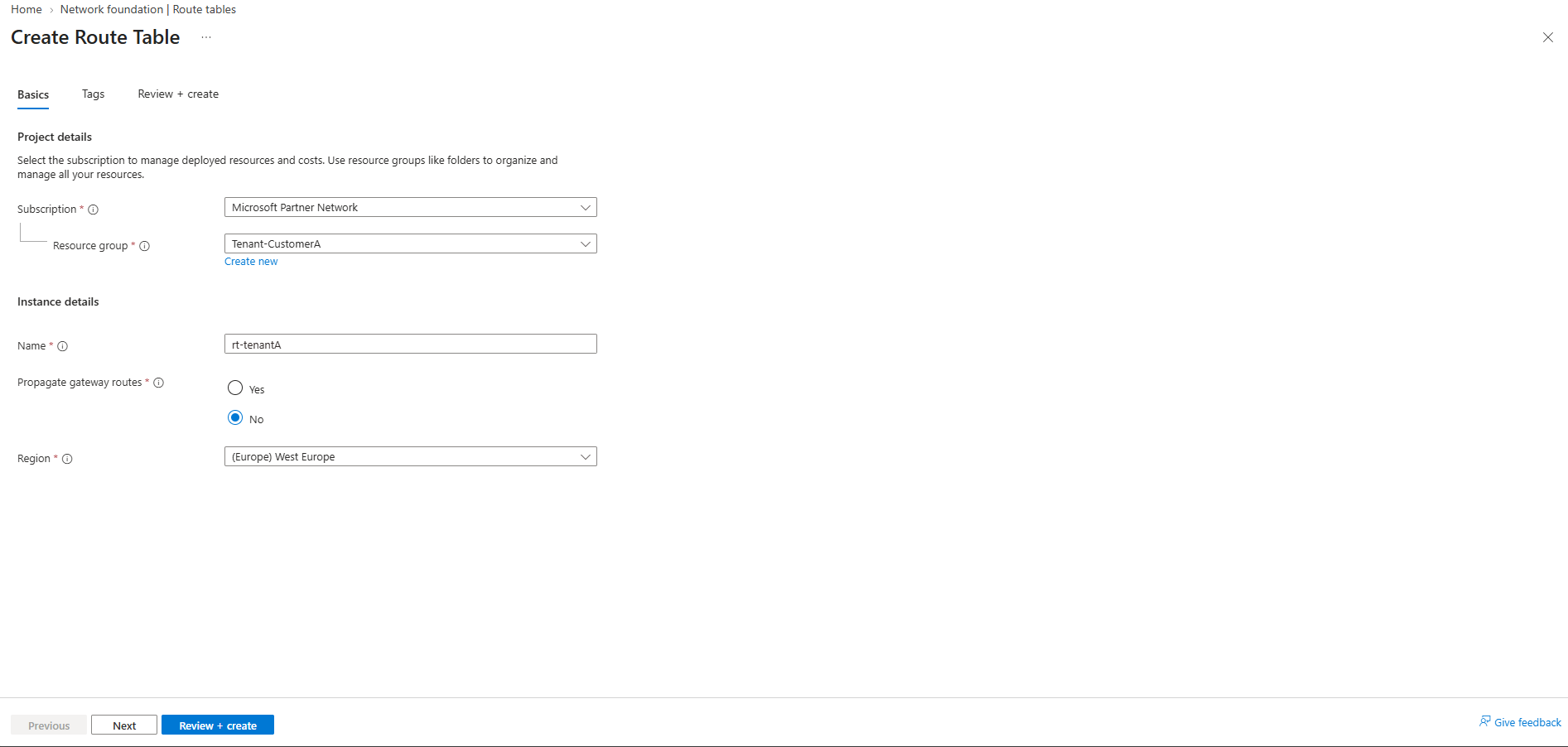
First, we create a dedicated Azure route table named rt-tenantA in the Tenant-CustomerA resource group.
When using an Azure Virtual Network Gateway, routes to on-premises networks can be propagated automatically to the Azure VNet, for example through BGP. Since our design uses pfSense instead of an Azure VPN Gateway, we must explicitly define the route to the HNV tenant network using an Azure User-Defined Route (UDR).
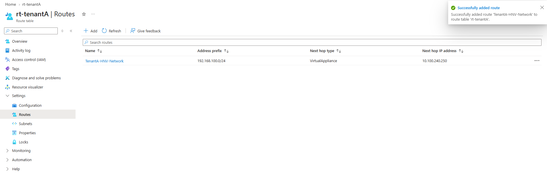
Next, we add the UDR TenantA-HNV-Network with destination 192.168.100.0/24 and select Virtual appliance as the next-hop type.
The next-hop address is the pfSense PERIMETER interface
10.100.240.250, ensuring that traffic from the Azure workload subnet toward the HNV tenant network is forwarded to pfSense.
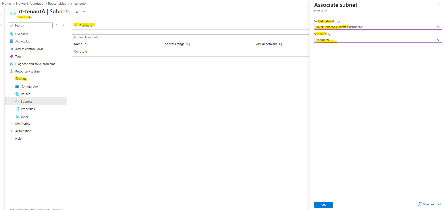
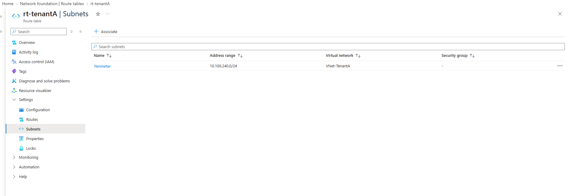
Finally, we associate the rt-tenantA route table with the Perimeter subnet (10.100.240.0/24), where VM-TenantA resides.
The UDR therefore becomes effective for the Azure workload, forwarding traffic destined for the HNV network
192.168.100.0/24to the pfSense virtual appliance at10.100.240.250.
We can verify the configuration by checking the Effective routes of the VM-TenantA network interface.
The UDR is now active and confirms that traffic destined for the HNV
Tenant-CustomerAnetwork (192.168.100.0/24) will be forwarded to the pfSense virtual appliance at10.100.240.250.
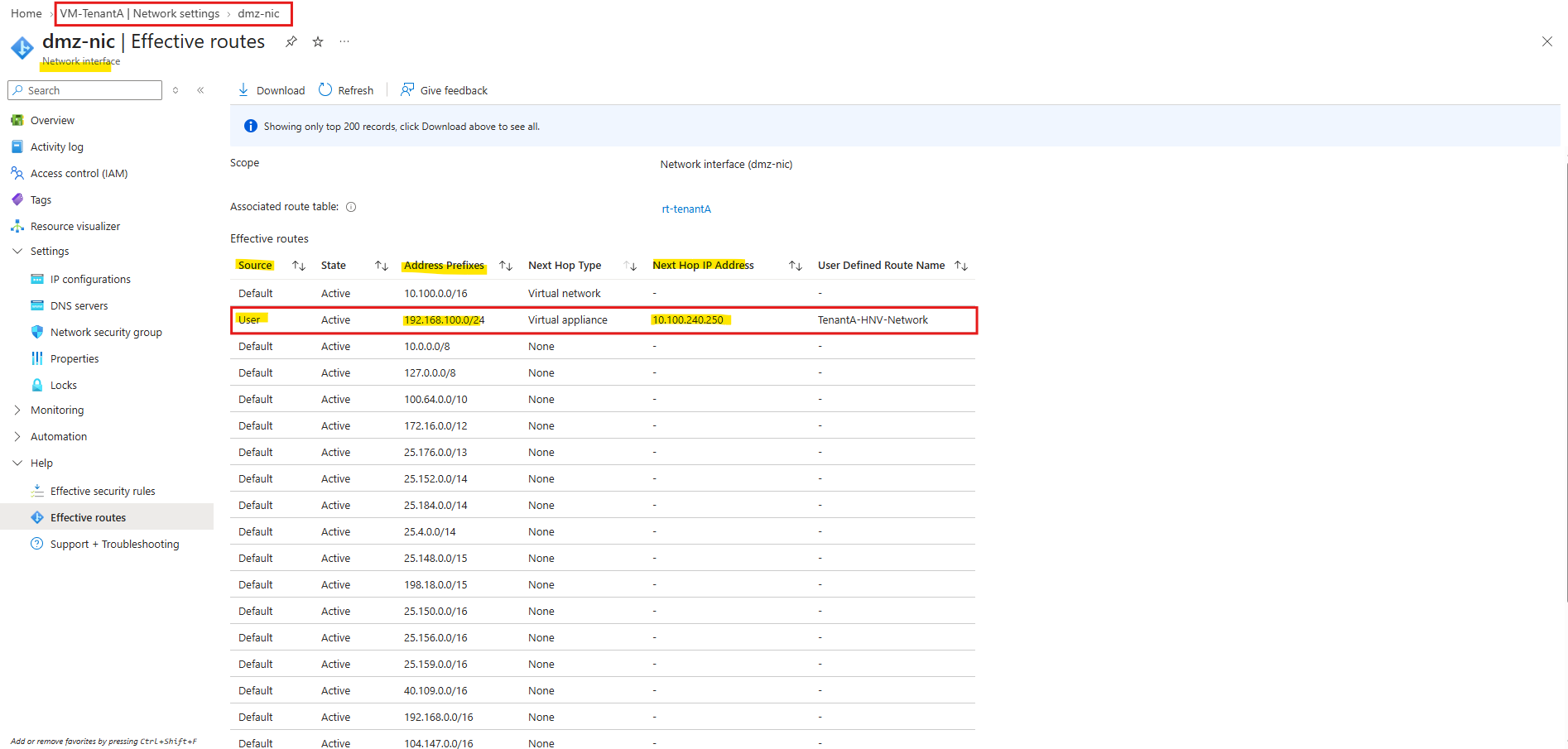
With the required routes now configured across Azure, pfSense, and the Ubuntu router, we can test the complete Tenant-CustomerA data path in both directions.
Testing the Tenant-CustomerA Connectivity
With the routing configured on Azure, pfSense, and the Ubuntu router, we can finally test end-to-end connectivity between the Azure and HNV Tenant-CustomerA networks.
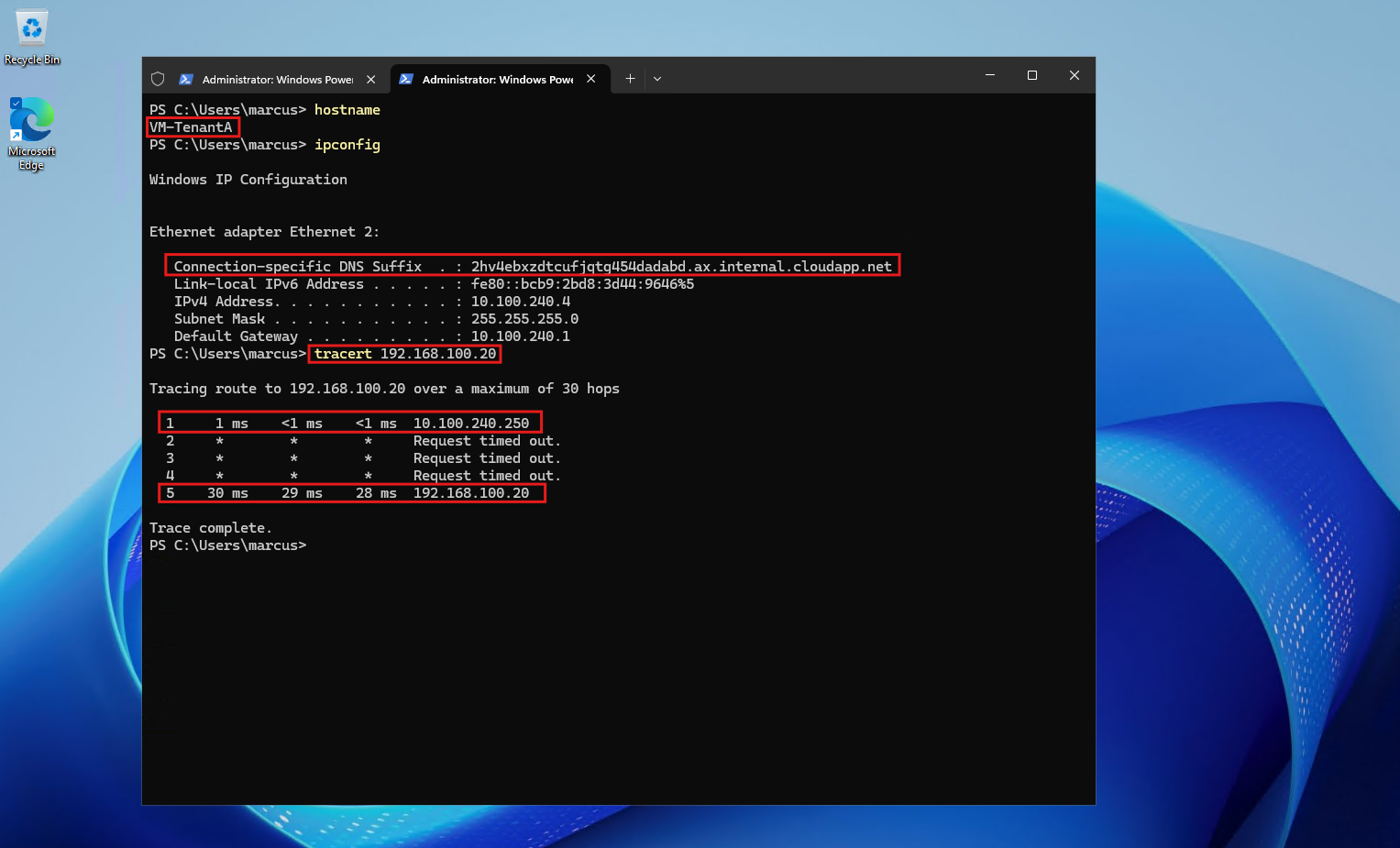
A traceroute in both directions confirms that traffic successfully traverses the pfSense IPsec VTI, the IPsec tunnel, the Ubuntu XFRM interface and VRF routing context, and the Microsoft SDN/HNV infrastructure.
Most importantly, the Azure-side traceroute shows
10.100.240.250as the first hop, confirming that our Azure UDR is forwarding HNV-bound traffic through pfSense as intended.
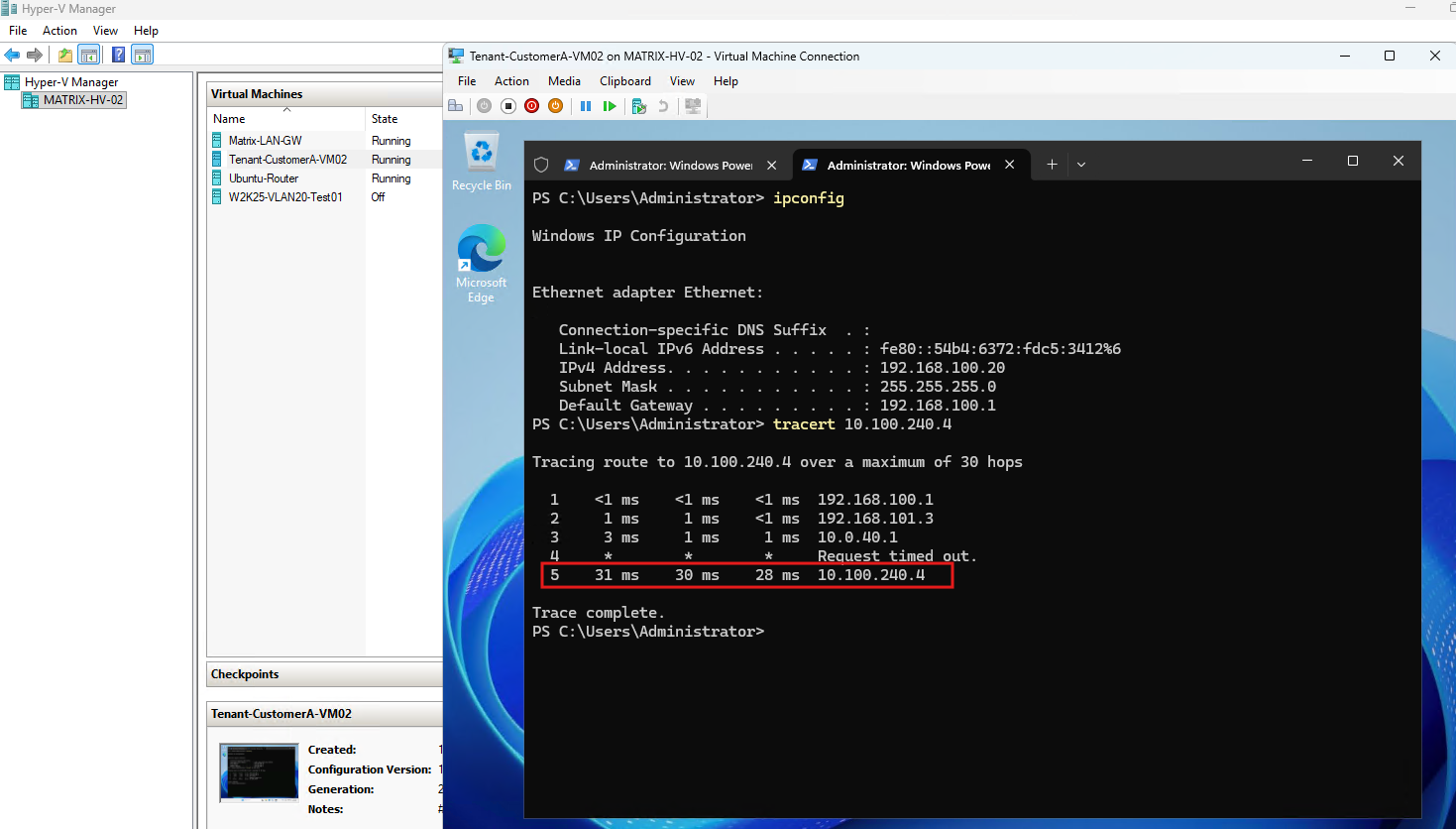
The traceroute from Tenant-CustomerA-VM02 (192.168.100.20) successfully reaches the Azure VM-TenantA workload (10.100.240.4), confirming connectivity from the HNV tenant network to Azure.
The traceroute also makes the on-premises forwarding path visible: traffic first reaches the HNV default gateway (
192.168.100.1), then the Microsoft SDN Gateway (192.168.101.3), and finally the Ubuntu router (10.0.40.1) before being forwarded through the Tenant-CustomerA IPsec tunnel to Azure.The intermediate IPsec path itself is not exposed as an additional traceroute hop, while the destination Azure VM (
10.100.240.4) is reached successfully.
The reverse traceroute from VM-TenantA (10.100.240.4) successfully reaches Tenant-CustomerA-VM02 (192.168.100.20), with pfSense (10.100.240.250) appearing as the first hop as defined by our Azure UDR.
Configuring Tenant-CustomerB
With Tenant-CustomerA fully configured and end-to-end connectivity verified, we can now add the second tenant.
The configuration follows the same principles, but uses a separate IPsec connection, XFRM interface, VRF routing context, pfSense router, and Azure VNet, allowing both tenants to operate independently despite the overlapping 192.168.100.0/24 HNV address space.
Configuring the Tenant-CustomerB IPsec Connection
For the second tenant, we will create another IKEv2/IPsec connection between the Ubuntu router and pfSense-TenantB. The tunnel will use its own VTI transit network:
pfSense-TenantB: 169.254.200.1/30
Ubuntu router: 169.254.200.2/30
On
pfSense-TenantB, we configure a second route-based IKEv2/IPsec tunnel using the same cryptographic parameters as forTenant-CustomerA, but with the dedicated Tenant B VTI network169.254.200.0/30.As before, the Azure WAN NIC is protected by an NSG allowing UDP 500 and UDP 4500 for IKE and IPsec NAT-T.
Configuring the Tenant-CustomerB strongSwan Connection
On the Ubuntu router, we create a separate strongSwan configuration for Tenant-CustomerB:
nano /etc/swanctl/conf.d/tenant-customerb.conf
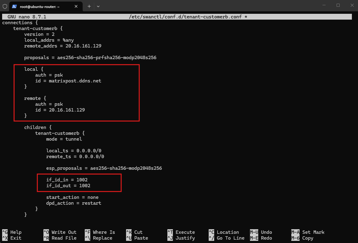
The configuration uses the public IP address of pfSense-TenantB (20.16.161.129) as the remote peer and XFRM interface ID 1002, corresponding to the existing vrf-tenant2 routing context:
connections {
    tenant-customerb {
        version = 2
        local_addrs = %any
        remote_addrs = 20.16.161.129

        proposals = aes256-sha256-prfsha256-modp2048s256

        local {
            auth = psk
            id = matrixpost.ddns.net
        }

        remote {
            auth = psk
            id = 20.16.161.129
        }

        children {
            tenant-customerb {
                mode = tunnel

                local_ts = 0.0.0.0/0
                remote_ts = 0.0.0.0/0

                esp_proposals = aes256-sha256-modp2048s256

                if_id_in = 1002
                if_id_out = 1002

                start_action = none
                dpd_action = restart
            }
        }

        dpd_delay = 10s
        rekey_time = 25920s
        over_time = 2880s
    }
}

secrets {
    ike-tenant-customerb {
        id-1 = matrixpost.ddns.net
        id-2 = 20.16.161.129
        secret = "YOUR-PRESHARED-KEY"
    }
}
After saving the file, we reload the strongSwan configuration:
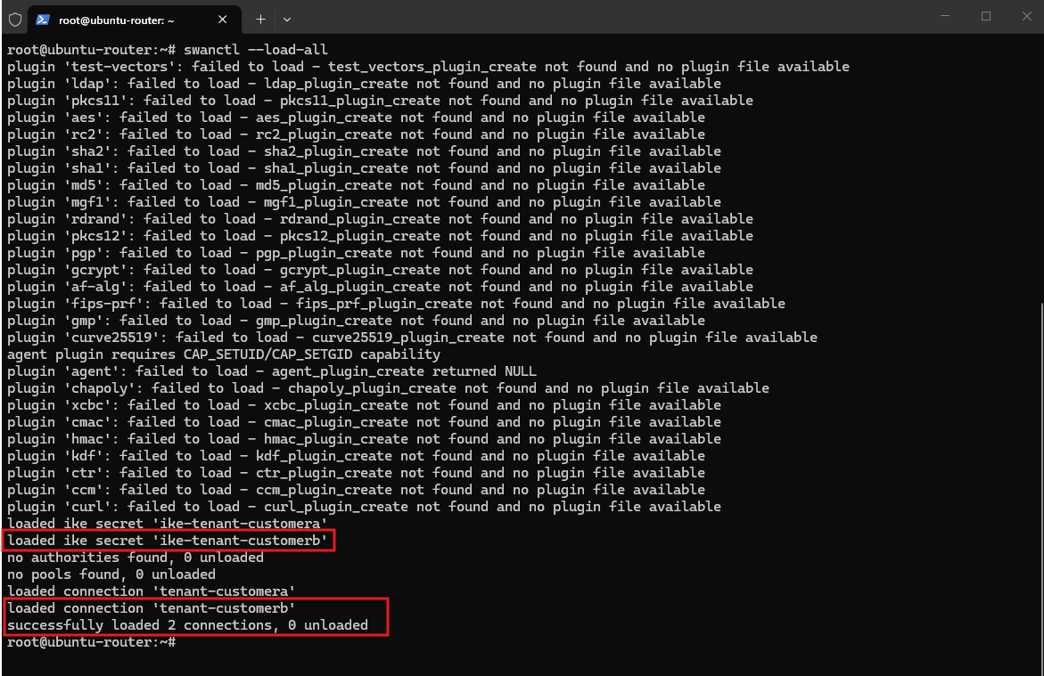
The output confirms that the new
tenant-customerbIKE secret and connection are loaded successfully. strongSwan now contains two independent IPsec configurations, one for each tenant.
swanctl --load-all
Creating the Tenant-CustomerB XFRM Interface
Before initiating the second IPsec connection, we create a dedicated XFRM interface for Tenant-CustomerB and attach it to the existing vrf-tenant2 VRF.
This places Tenant B VPN traffic into routing table 1002, keeping it completely separate from Tenant A despite both HNV tenants using 192.168.100.0/24.
As with Tenant-CustomerA, the XFRM interface, its VRF assignment, transit address, and interface state configured below modify only the current runtime network state and will not survive a reboot; we will make it persistent later.
ip link add ipsec-tenant2 type xfrm if_id 1002
ip link set ipsec-tenant2 master vrf-tenant2
ip addr add 169.254.200.2/30 dev ipsec-tenant2
ip link set ipsec-tenant2 up

Then verify:
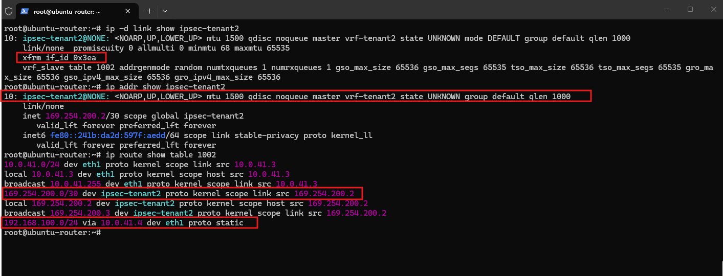
The output confirms that
ipsec-tenant2is associated withvrf-tenant2and uses XFRM interface ID1002(0x3ea). The dedicated169.254.200.0/30VPN transit network is installed in routing table1002, alongside the existing route to the overlappingTenant-CustomerBHNV network (192.168.100.0/24) through the SDN Gateway at10.0.41.4.
ip -d link show ipsec-tenant2
ip addr show ipsec-tenant2
ip route show table 1002
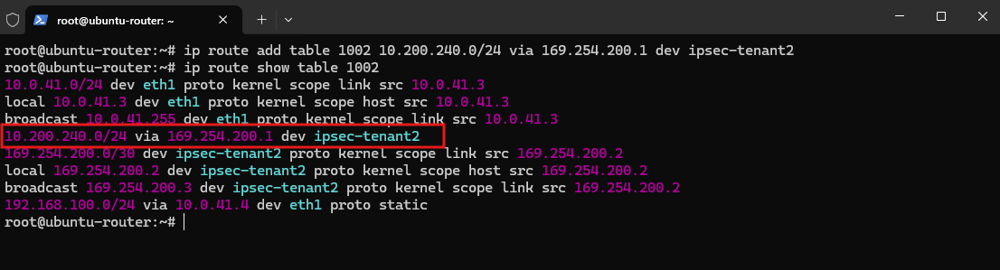
With ipsec-tenant2 attached to vrf-tenant2, we now add the route to the Azure Tenant B network (10.200.240.0/24) to routing table 1002. Traffic destined for Azure is forwarded through the Tenant-CustomerB XFRM interface to the pfSense VTI peer at 169.254.200.1.
This route is added only to the current runtime routing table and will not survive a reboot; we will therefore add the complete Tenant-CustomerB XFRM configuration to the existing systemd service.
ip route add table 1002 10.200.240.0/24 via 169.254.200.1 dev ipsec-tenant2

Then verify:
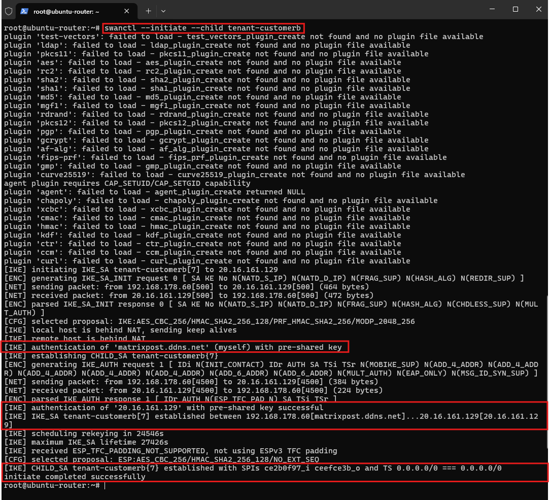
Now we’re ready to initiate Tenant B:
The second IPsec connection establishes successfully on the first attempt. The output confirms successful PSK authentication, followed by establishment of the
tenant-customerbIKE_SA and CHILD_SA using the dedicated Tenant B XFRM context.
swanctl --initiate --child tenant-customerb
The IPsec status on
pfSense-TenantBconfirms that both IKEv2 Phase 1 and the route-based Phase 2 CHILD_SA are established, completing the second independent IPsec tunnel between Azure and the Ubuntu router.
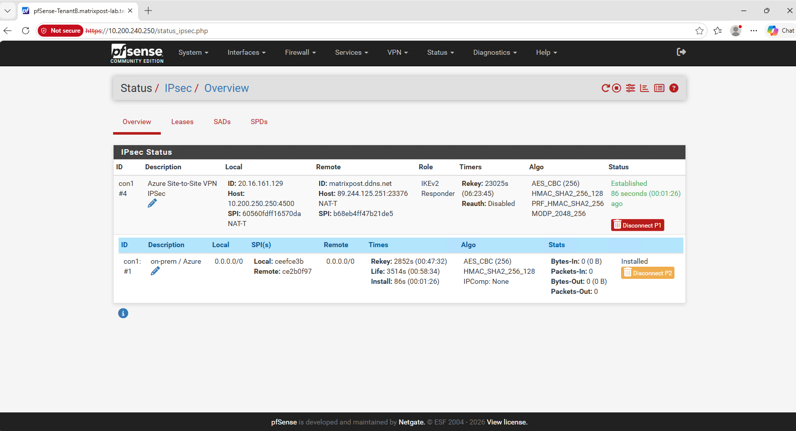
At this point, the original Tenant-CustomerA IPsec tunnel remains established while the new Tenant-CustomerB tunnel is brought online, confirming that the Ubuntu router can maintain both tenant-specific IPsec connections simultaneously.
As with Tenant-CustomerA, we add a route for the Azure Tenant-CustomerB network (10.200.240.0/24) to routing table 1002, using the pfSense VTI endpoint 169.254.200.1 through ipsec-tenant2.
This keeps all Tenant B traffic within its dedicated VRF routing context.
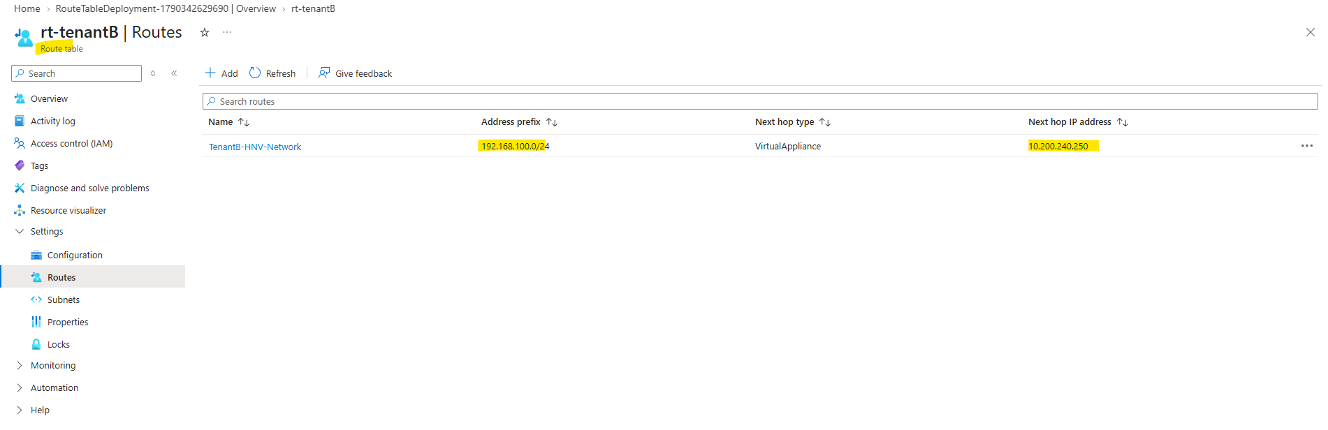
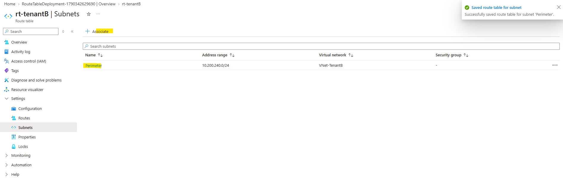
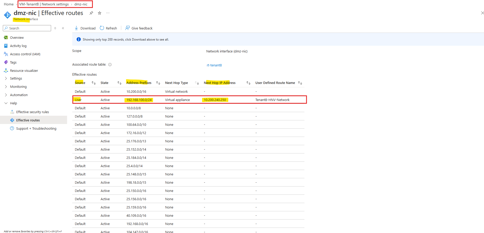
The effective routes on
VM-TenantBconfirm that traffic for the overlapping HNV network192.168.100.0/24is now forwarded topfSense-TenantBat10.200.240.250.
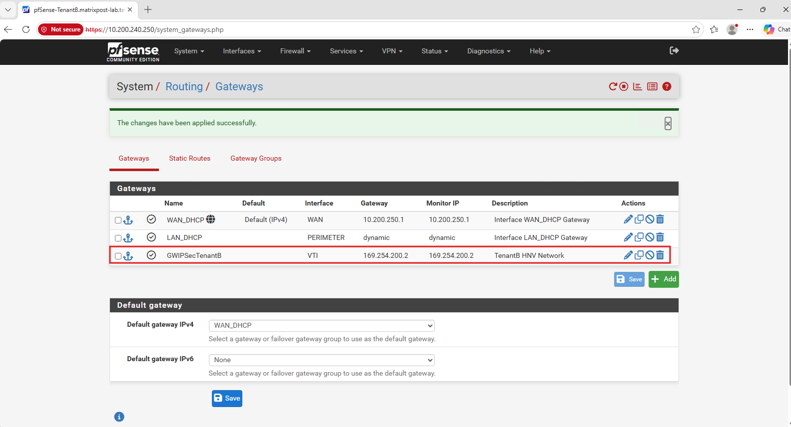
On pfSense-TenantB, we create a dedicated VTI gateway using the Ubuntu tunnel endpoint 169.254.200.2 as the next hop.
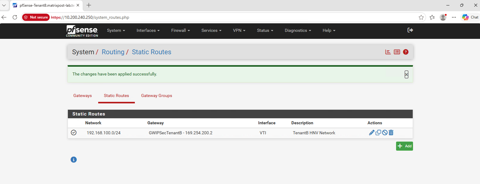
We then add a static route for the HNV Tenant-CustomerB network (192.168.100.0/24) through this gateway, ensuring that traffic is forwarded into the Tenant B IPsec tunnel.
With the required routes now configured across Azure, pfSense, and the Ubuntu router, we can test the complete Tenant-CustomerB data path in both directions.
Making the Tenant-CustomerB XFRM Configuration Persistent
We now extend the previously created tenant-xfrm.service with the corresponding XFRM interface and routing configuration for Tenant-CustomerB.
Edit:
nano /etc/systemd/system/tenant-xfrm.service
The complete service should now contain both tenants:
[Unit]
Description=Tenant XFRM interfaces and VRF routes
After=network-online.target
Wants=network-online.target

[Service]
Type=oneshot
RemainAfterExit=yes

ExecStart=/usr/sbin/ip link add ipsec-tenant1 type xfrm if_id 1001
ExecStart=/usr/sbin/ip link set ipsec-tenant1 master vrf-tenant1
ExecStart=/usr/sbin/ip addr add 169.254.100.2/30 dev ipsec-tenant1
ExecStart=/usr/sbin/ip link set ipsec-tenant1 up
ExecStart=/usr/sbin/ip route add 10.100.240.0/24 via 169.254.100.1 dev ipsec-tenant1 table 1001

ExecStart=/usr/sbin/ip link add ipsec-tenant2 type xfrm if_id 1002
ExecStart=/usr/sbin/ip link set ipsec-tenant2 master vrf-tenant2
ExecStart=/usr/sbin/ip addr add 169.254.200.2/30 dev ipsec-tenant2
ExecStart=/usr/sbin/ip link set ipsec-tenant2 up
ExecStart=/usr/sbin/ip route add 10.200.240.0/24 via 169.254.200.1 dev ipsec-tenant2 table 1002

ExecStop=/usr/sbin/ip link del ipsec-tenant1
ExecStop=/usr/sbin/ip link del ipsec-tenant2

[Install]
WantedBy=multi-user.target
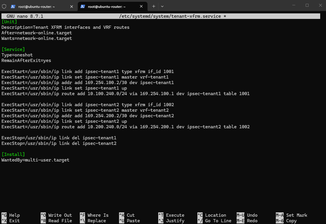
Then:
systemctl daemon-reload
No need for another systemctl enable because tenant-xfrm.service is already enabled from the Tenant A section.
And don’t start/restart it now, since both XFRM interfaces already exist.
A systemd oneshot service executes one or more commands once during service startup and then exits, rather than running continuously as a daemon.
With
RemainAfterExit=yes, systemd considers the service active even after its commands have completed, which makes it well suited for applying persistent network configuration during boot.More about here.
Testing the Tenant-CustomerB Connectivity
With the routing configuration complete, we can now verify end-to-end connectivity in both directions between the HNV Tenant-CustomerB network and the corresponding Azure Tenant B network.
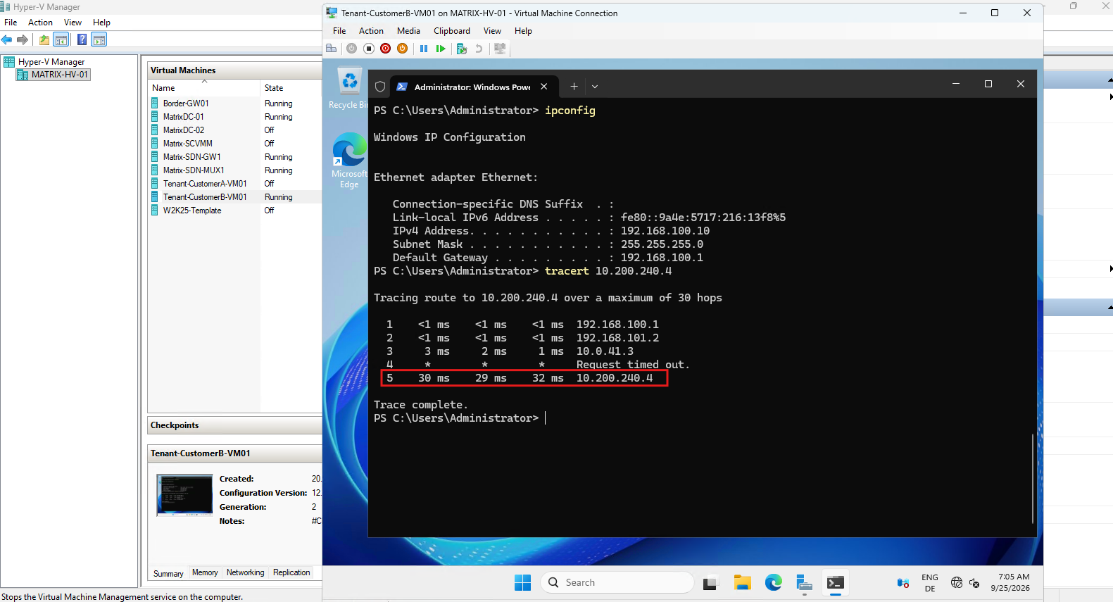
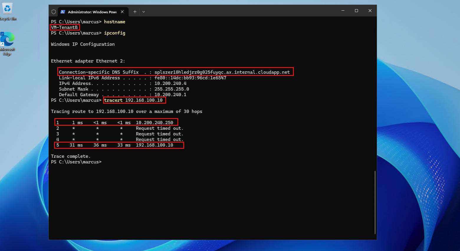
From Tenant-CustomerB-VM01 (192.168.100.10), a traceroute to Azure VM-TenantB (10.200.240.4) successfully reaches the remote VM through the Tenant-CustomerB VRF and IPsec tunnel.
The traceroute shows the equivalent forwarding path for Tenant-CustomerB: traffic first reaches the HNV default gateway (
192.168.100.1), then the Microsoft SDN Gateway (192.168.101.2), and finally the Ubuntu router (10.0.41.3) before being forwarded through the Tenant-CustomerB IPsec tunnel to Azure.The destination Azure VM (
10.200.240.4) is then reached successfully, demonstrating that both overlapping HNV tenants follow their own isolated forwarding paths.
In the opposite direction, a traceroute from Azure VM-TenantB (10.200.240.4) successfully reaches Tenant-CustomerB-VM01 (192.168.100.10), confirming that the return path through pfSense, the IPsec tunnel, and the HNV infrastructure is also working correctly.
Capturing Both IPsec Tunnel Connections
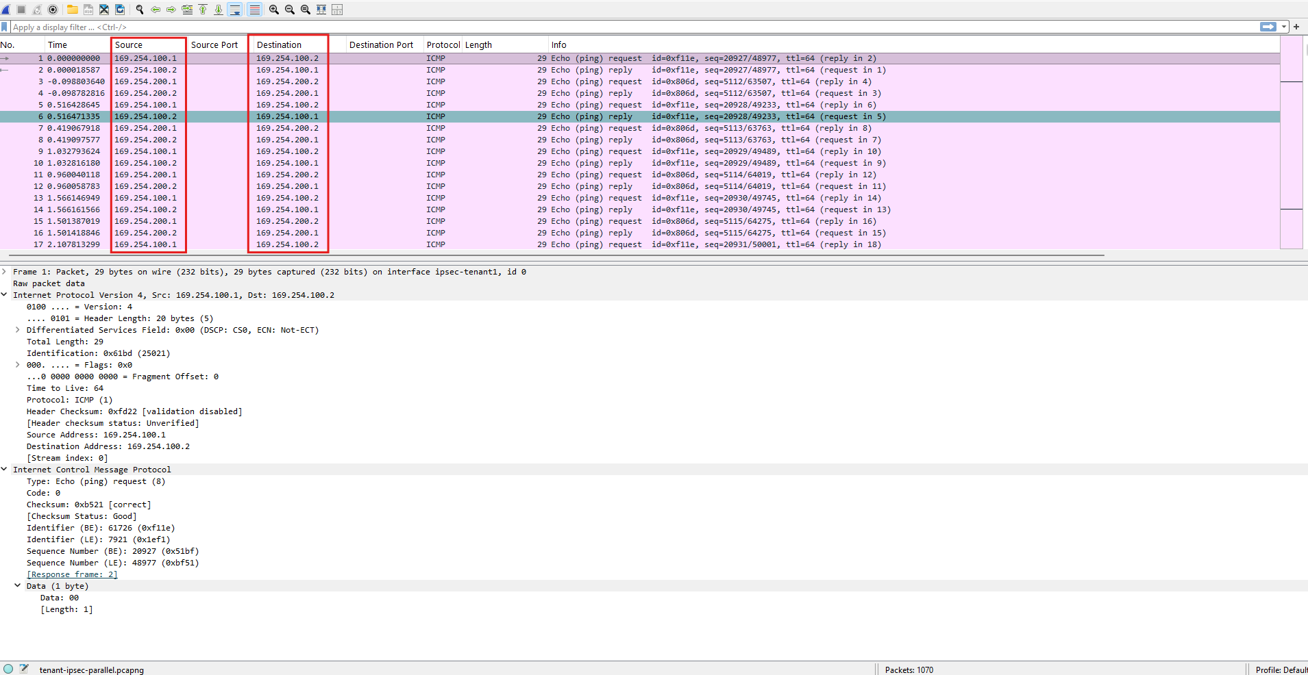
With both tenant connections operational, we can perform a final packet capture on the Ubuntu router while generating traffic between both Azure VNets and their corresponding HNV tenant networks simultaneously.
This allows us to verify that both IPsec tunnels are active at the same time and that traffic remains associated with the correct XFRM interface and VRF routing context, despite both HNV tenants using the overlapping 192.168.100.0/24 address space.
We start a capture on the Ubuntu router covering both XFRM interfaces while we generate traffic for both tenants simultaneously.
The Wireshark capture shows traffic from both IPsec connections simultaneously. The
169.254.100.0/30flow is carried throughipsec-tenant1, while the169.254.200.0/30flow is carried throughipsec-tenant2, demonstrating that both tenant VPN connections remain separated on the Ubuntu router while operating in parallel.
tshark -i ipsec-tenant1 -i ipsec-tenant2 -f "icmp" -w /tmp/tenant-ipsec-parallel.pcapng
Monitoring the IPsec Tunnel Connections
For a continuously updated overview of the strongSwan IKE and CHILD SAs, the swanctl --list-sas command can be combined with the Linux watch utility. This provides a simple console-based monitoring view showing the current tunnel state, negotiated parameters, traffic counters, and rekey information for both tenant connections.
watch -n 1 'swanctl --list-sas 2>/dev/null'
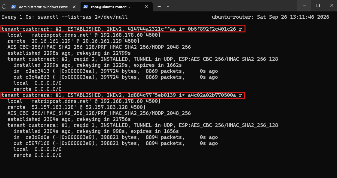
The continuously refreshed output above provides a compact overview of both tenant VPN connections.
In this example, both IKEv2 connections are ESTABLISHED, their CHILD_SAs are INSTALLED, and the increasing inbound and outbound byte and packet counters confirm that traffic is actively being processed through both IPsec tunnels.
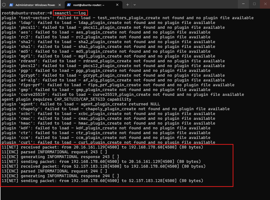
For troubleshooting tunnel establishment, rekeying, or other IKE/IPsec events, strongSwan also provides a live log stream through its VICI interface:
The
swanctl --logcommand provides a live view of strongSwan events through the VICI interface. In this example, IKEv2INFORMATIONALexchanges from both Azure pfSense peers can be observed in real time, making the command particularly useful for monitoring tunnel activity and troubleshooting tunnel establishment, rekeying, and connectivity issues.
swanctl --log
To monitor the underlying Linux kernel XFRM state and its packet/byte counters instead, the following command can be used:
watch -n 1 'ip -s xfrm state'
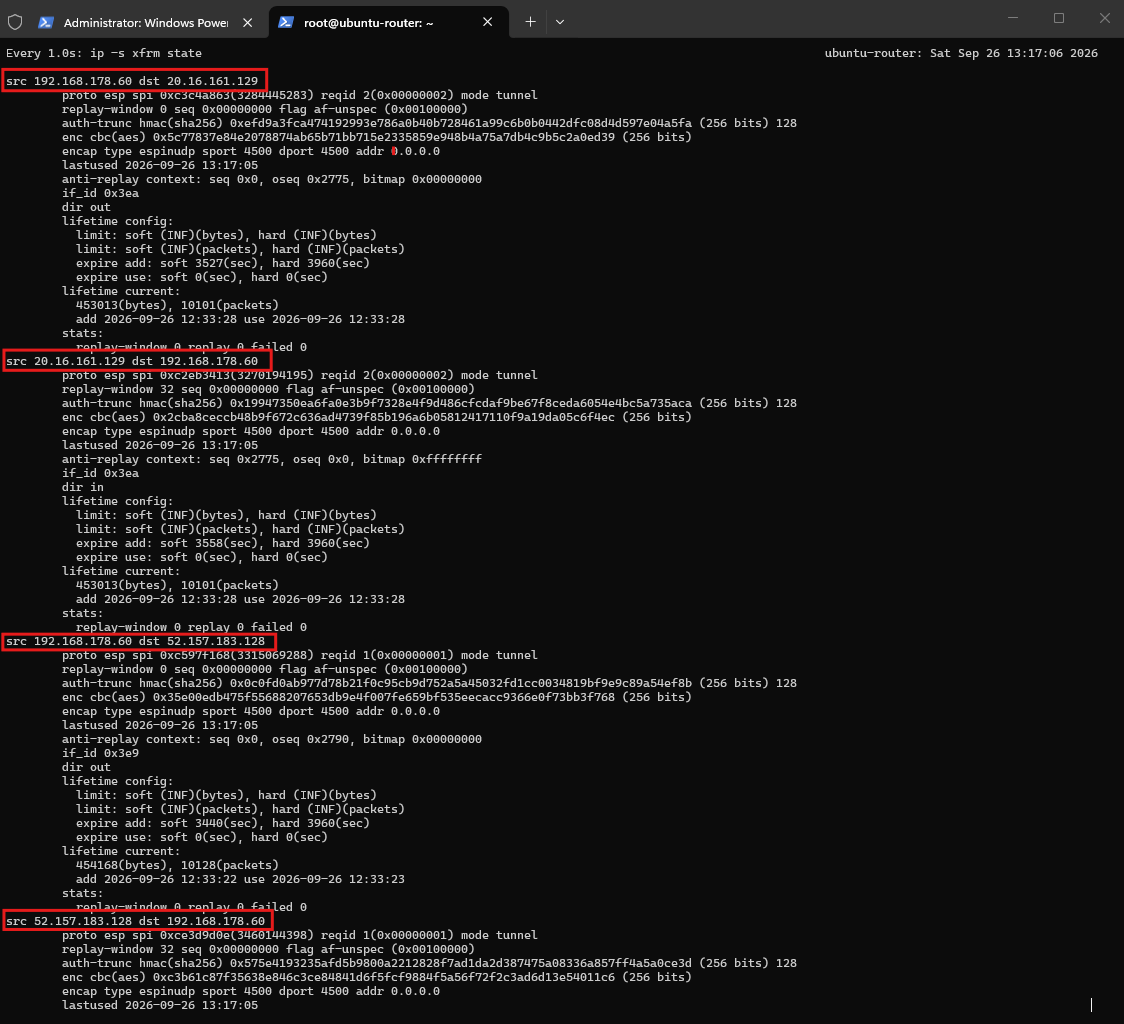
The ip -s xfrm state output above provides a lower-level view of the IPsec Security Associations installed in the Linux kernel.
Here, separate inbound and outbound XFRM states can be seen for both Azure peers, including their interface IDs (1001 and 1002), SPIs, cryptographic parameters, lifetime information, and packet and byte counters. While swanctl --list-sas shows the strongSwan/IKE perspective, this view confirms the actual IPsec state maintained by the Linux XFRM datapath.
Links
strongSwan
https://strongswan.org/XFRM Framework
https://cdn.kernel.org/doc/html/latest/networking/xfrm/index.htmlswanctl.conf
https://docs.strongswan.org/docs/latest/swanctl/swanctlConf.htmlVirtual xfrm interfaces
https://lwn.net/Articles/757391/XFRM Interfaces on Linux
https://docs.strongswan.org/docs/latest/features/routeBasedVpn.html#_xfrm_interfaces_on_linuxConfiguring IP tunnels
https://docs.redhat.com/en/documentation/red_hat_enterprise_linux/8/html/configuring_and_managing_networking/configuring-ip-tunnels_configuring-and-managing-networking