Microsoft Hyper-V Networking Best Practices – Part 4 – Managing Hyper-V with SCVMM and Comparing It with VMware vCenter
So far, we have built and managed our Hyper-V environment using Hyper-V Manager, Failover Cluster Manager, and PowerShell. While these tools provide everything required to manage individual hosts and clusters, larger environments quickly benefit from a centralized management platform.
In this fourth part, we will install and configure System Center Virtual Machine Manager (SCVMM) and add our existing Hyper-V cluster to it. We will then explore how SCVMM centralizes the management of Hyper-V hosts, clusters, virtual machines, storage, and networking, including concepts such as Logical Networks and Logical Switches.
Finally we will compare SCVMM with VMware vCenter and look at the similarities and differences between the two approaches to centralized virtualization management.
Installing System Center Virtual Machine Manager (SCVMM)
Before we can centrally manage our Hyper-V infrastructure, we first need to deploy System Center Virtual Machine Manager (SCVMM).
SCVMM acts as the central management platform for Hyper-V environments and brings hosts, clusters, virtual machines, networking, and storage together within a single management layer.
In this section, we will install the required SCVMM components and prepare the management server. Once the installation is complete, we can connect our existing two-node Hyper-V Failover Cluster and start exploring how SCVMM manages the environment compared with the individual Hyper-V and Failover Cluster management tools used so far.
When creating a new virtual machine that should be highly available from the beginning, we can create it directly from Failover Cluster Manager → Roles → Virtual Machines → New Virtual Machine.
In contrast to creating the VM first in Hyper-V Manager, the VM is automatically registered as a highly available cluster role during creation, eliminating the additional step of configuring it for high availability afterwards.
The VM files should be stored on the Cluster Shared Volume (CSV) so that they are accessible from all cluster nodes.
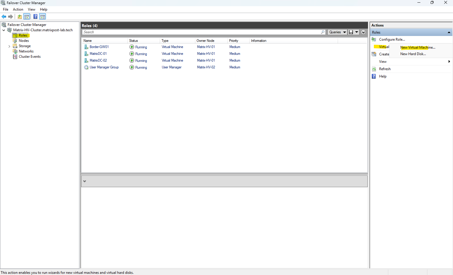
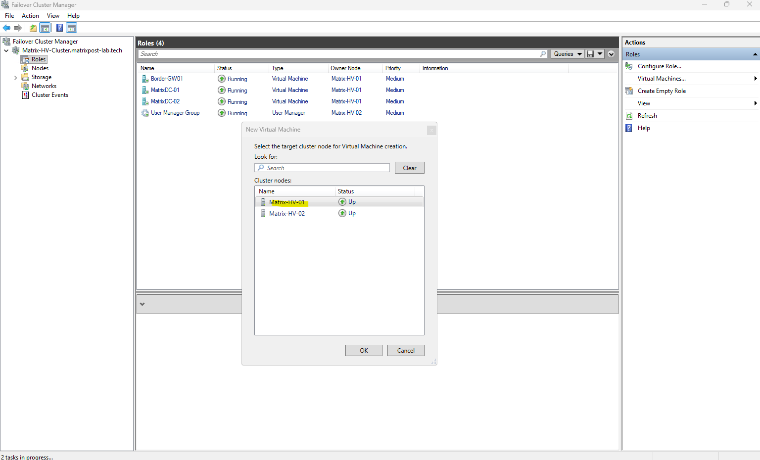
When creating a new virtual machine from Failover Cluster Manager, we first select the cluster node on which the VM should initially be created and run.
In our example, we select Matrix-HV-01. This only defines the VM’s initial owner; because the VM will be configured as a highly available cluster role, ownership can later move between the cluster nodes during Live Migration or failover.
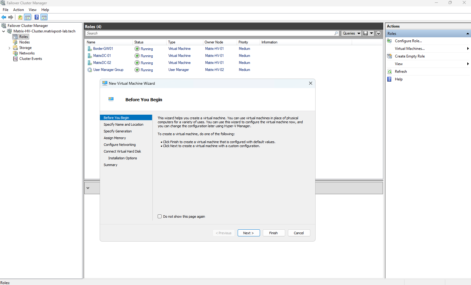
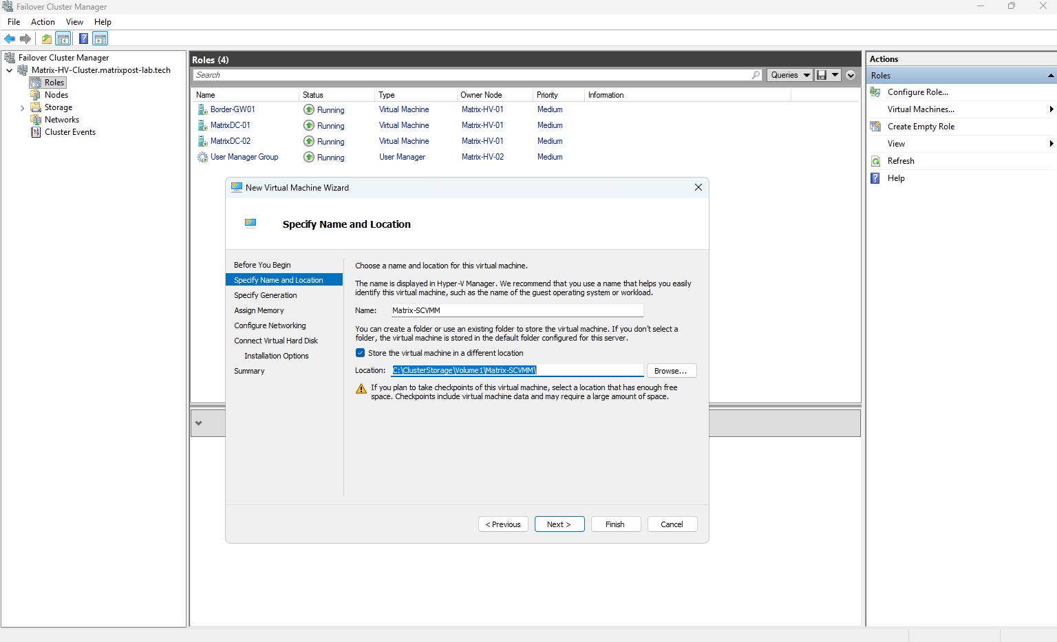
Since this virtual machine will be highly available, we store its files directly on the Cluster Shared Volume (CSV) instead of using the local default storage location of the selected Hyper-V host. Therefore, select Store the virtual machine in a different location and specify C:\ClusterStorage\Volume1\Matrix-SCVMM\.
As a best practice, create a dedicated folder for each virtual machine on the CSV. Otherwise, the VM configuration files and other associated files could end up directly in the root of
Volume1, quickly making the shared storage difficult to manage.
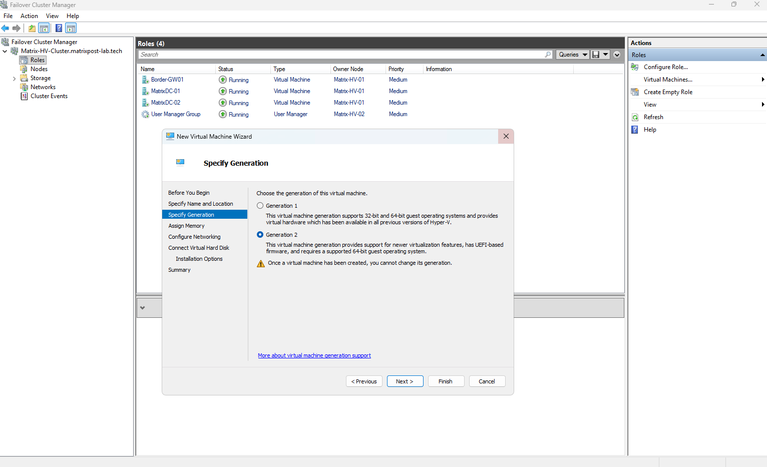
Next, select Generation 2 for the virtual machine. Generation 2 VMs use modern virtual hardware with UEFI firmware and support features such as Secure Boot, making them the preferred choice for modern Windows Server operating systems.
Keep in mind that the VM generation cannot be changed after the virtual machine has been created.
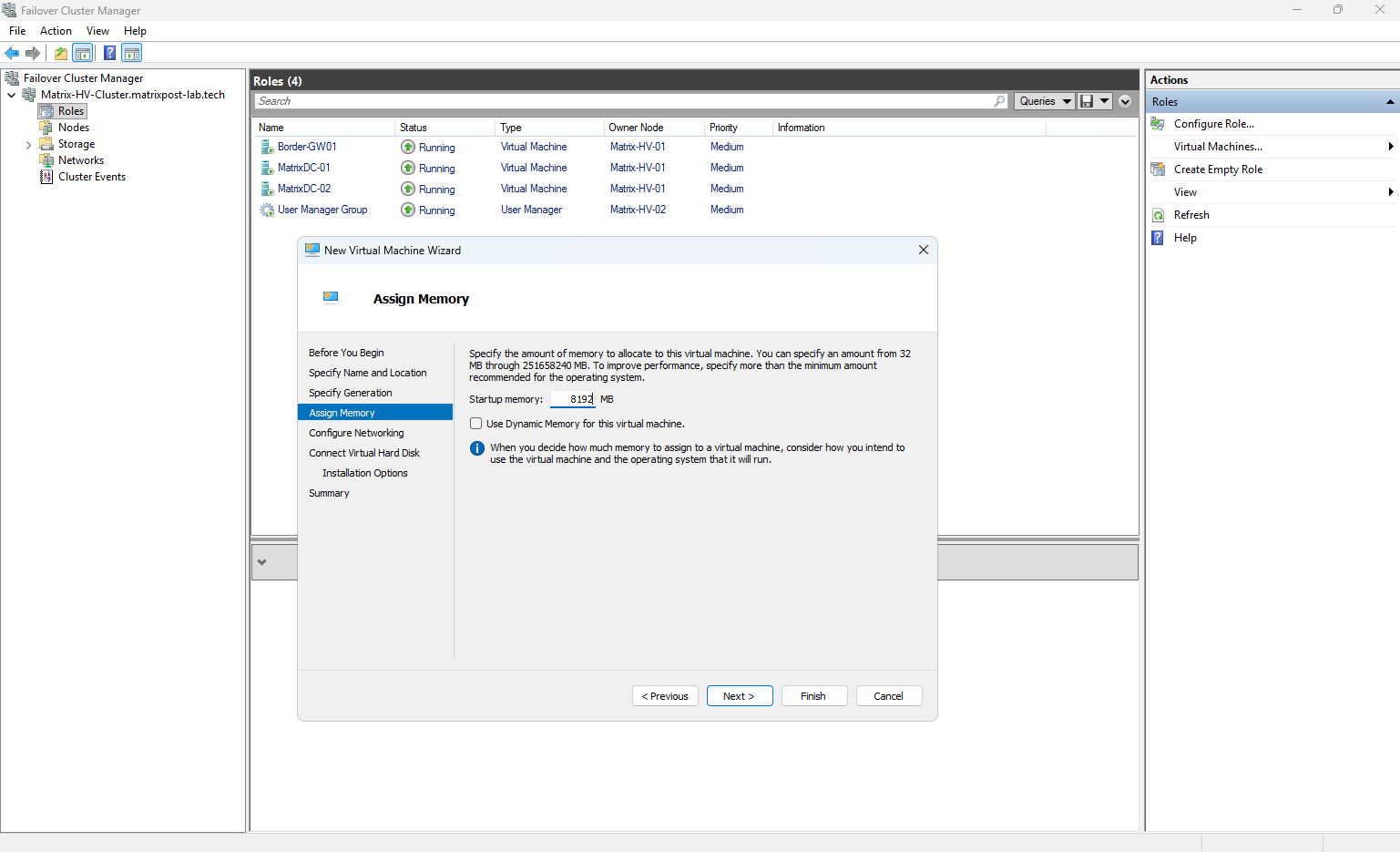
Next, assign the required memory to the virtual machine. For our Matrix-SCVMM server, we initially assign 8 GB (8192 MB) of static memory and leave Dynamic Memory disabled.
Since this is a lab environment with limited physical resources, we can adjust the memory allocation later if required.
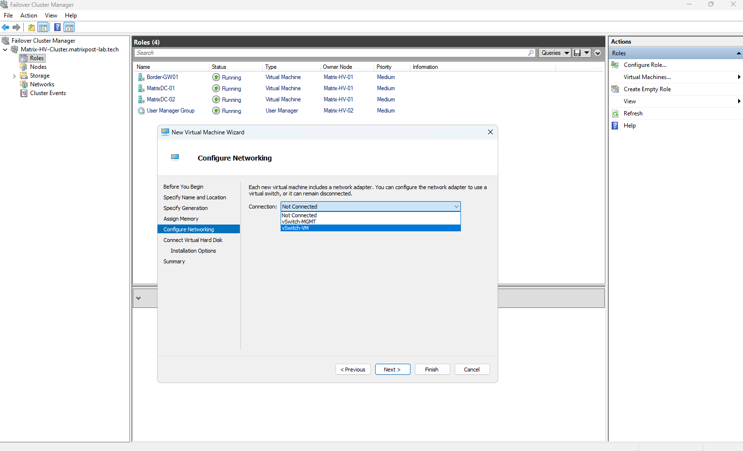
Next, connect the virtual machine to our vSwitch-VM virtual switch. This is the Switch Embedded Teaming (SET) based vSwitch we configured earlier using the two dedicated physical VM network adapters, providing network redundancy for our virtual machines.
We do not use vSwitch-MGMT, as this switch is dedicated to the Hyper-V host management network.
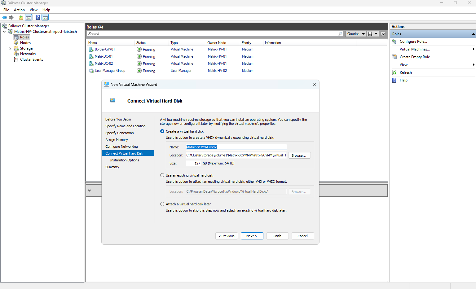
Next, create the virtual hard disk for the Matrix-SCVMM VM. We use the modern VHDX format and configure a 127 GB dynamically expanding disk, which only consumes physical storage as data is actually written to it.
Notice that Hyper-V automatically creates its standard folder structure below our previously specified
Matrix-SCVMMVM directory. Therefore, we only need to define the dedicated VM folder at the previous step; Hyper-V takes care of organizing the configuration and virtual hard disk files underneath it.
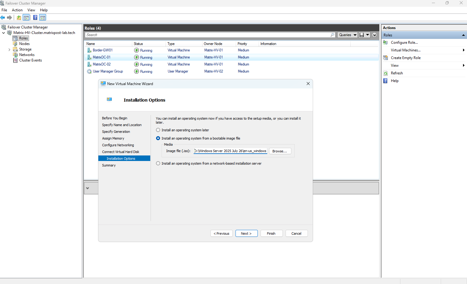
Next, select the Windows Server 2025 ISO image as the installation media.
Although the SCVMM management server will run System Center Virtual Machine Manager 2022, we are using Windows Server 2025 as the guest operating system for the management VM.
For this lab, we will use System Center Standard 2022, as this is the version currently provided through my Microsoft AI Cloud Partner Program benefits.
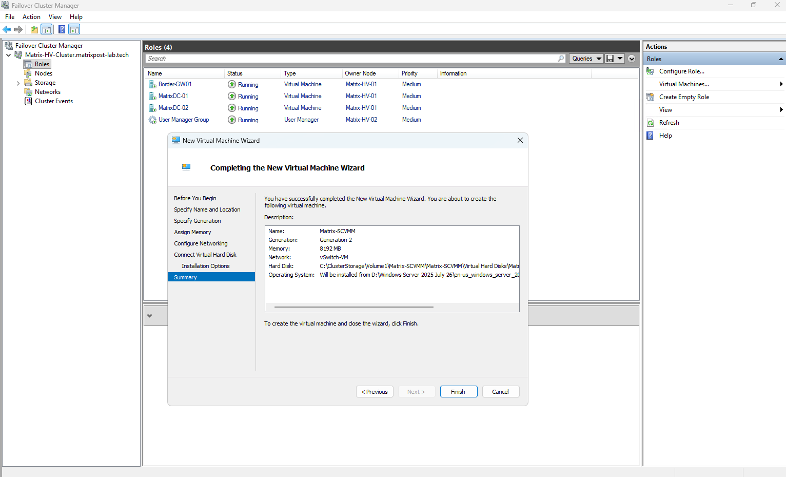
Finally, review the virtual machine configuration before clicking Finish.
Our Matrix-SCVMM VM will be created as a Generation 2 VM with 8 GB RAM, connected to the vSwitch-VM, while its configuration and virtual disk are stored on the Cluster Shared Volume (CSV).
The Windows Server 2025 ISO is already attached for the operating system installation.
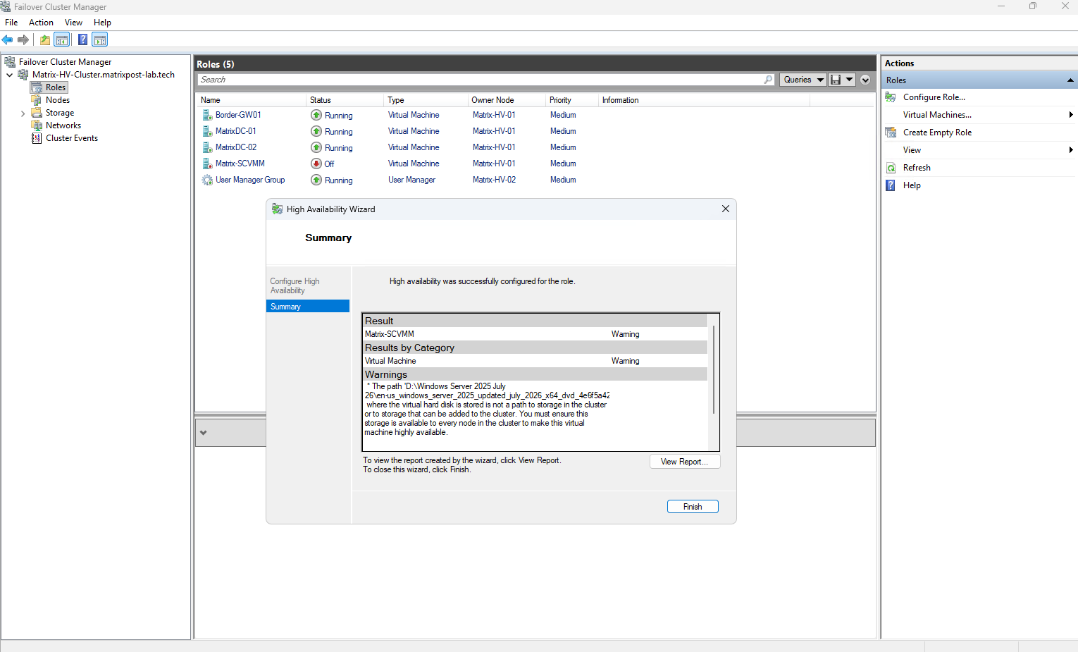
After the VM has been created, Failover Cluster Manager automatically runs the High Availability Wizard and adds the new Matrix-SCVMM VM as a clustered role.
In our case, the VM was successfully added, but the wizard reports a warning because the attached Windows Server 2025 ISO is located on the local
D:drive of Matrix-HV-01 and is therefore not accessible from the other cluster node.
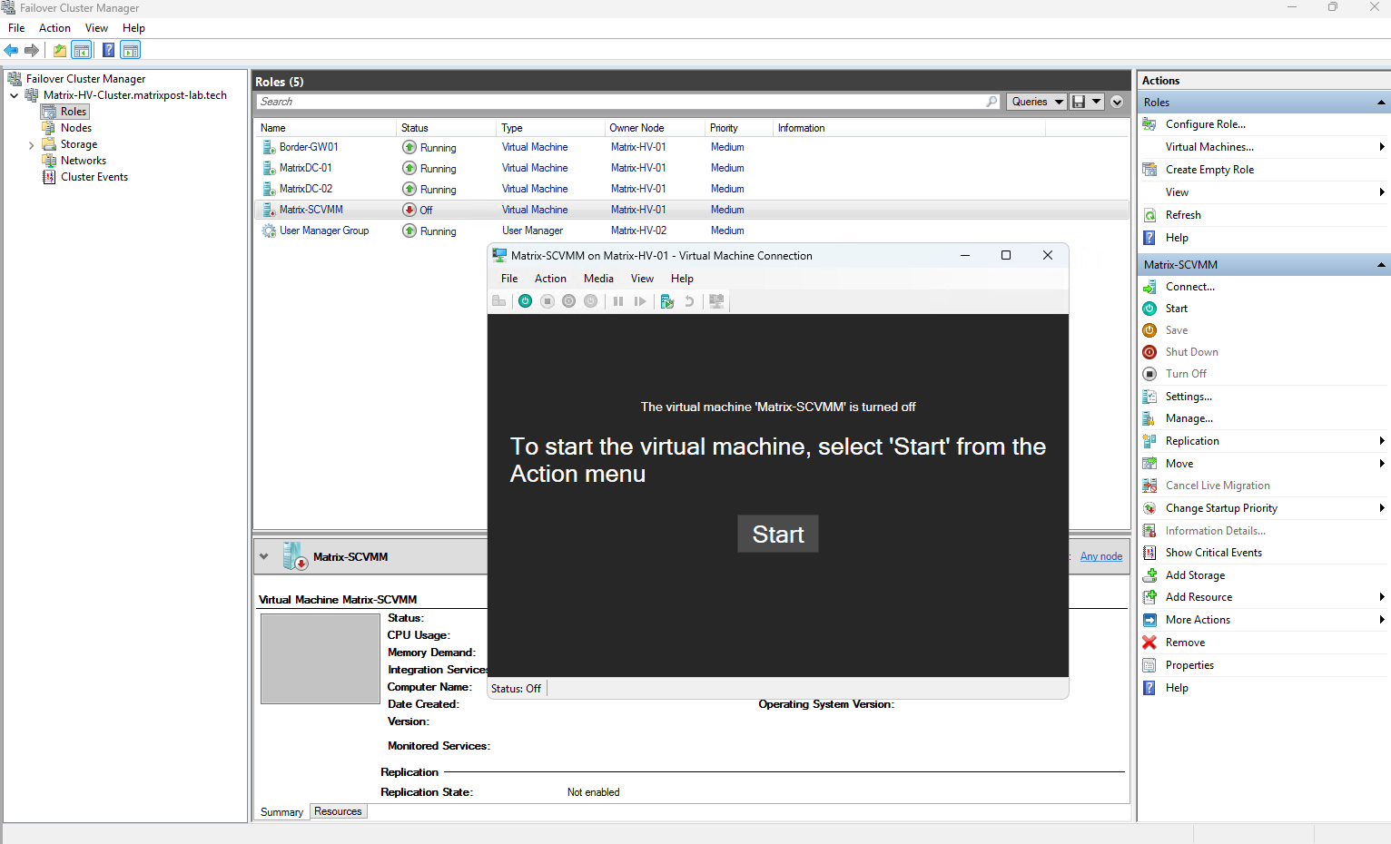
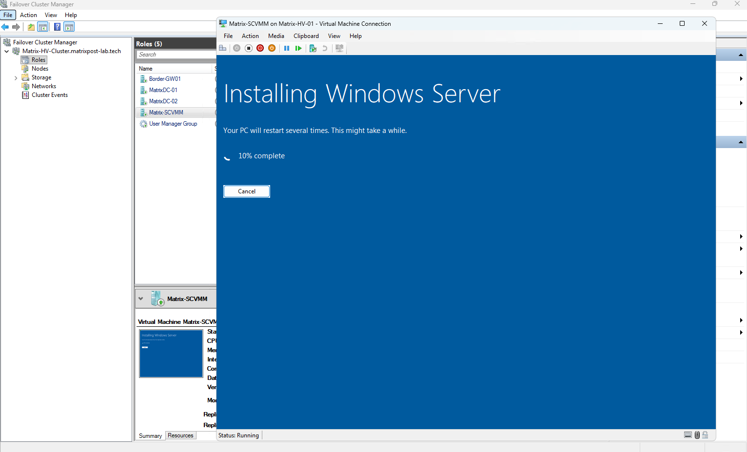
With the Matrix-SCVMM VM created and automatically registered as a highly available cluster role, we can connect to the VM directly from Failover Cluster Manager and start it to begin the Windows Server installation.
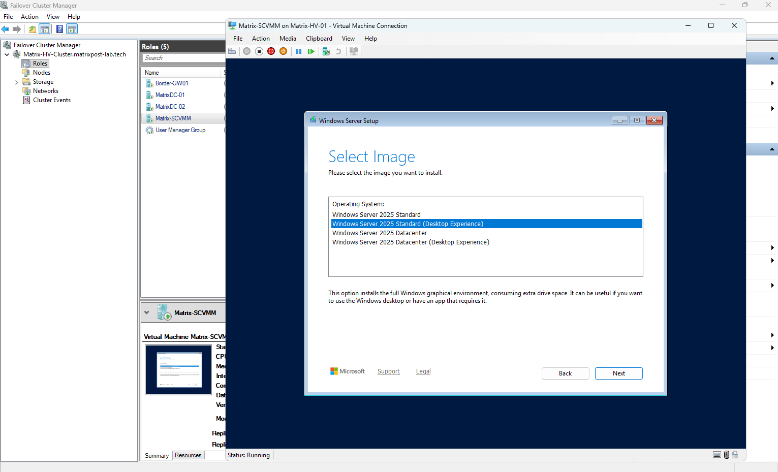
For the SCVMM management server, I am installing Windows Server 2025 Standard with Desktop Experience.
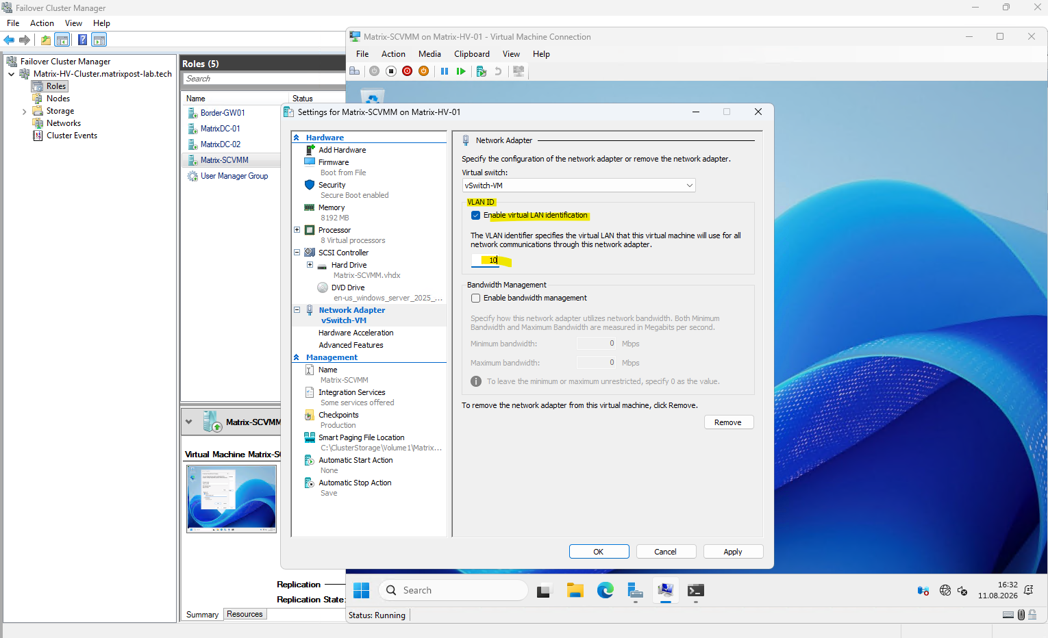
Because our VM network uses VLAN 10, we also need to configure the VLAN ID directly on the virtual network adapter of the VM.
For now, we configure the VLAN ID directly on the VM’s virtual network adapter. Later, after deploying SCVMM, we will centralize and abstract this configuration using Logical Networks and VM Networks, making VLAN management across multiple Hyper-V hosts considerably easier and more comparable to networking in VMware vSphere.
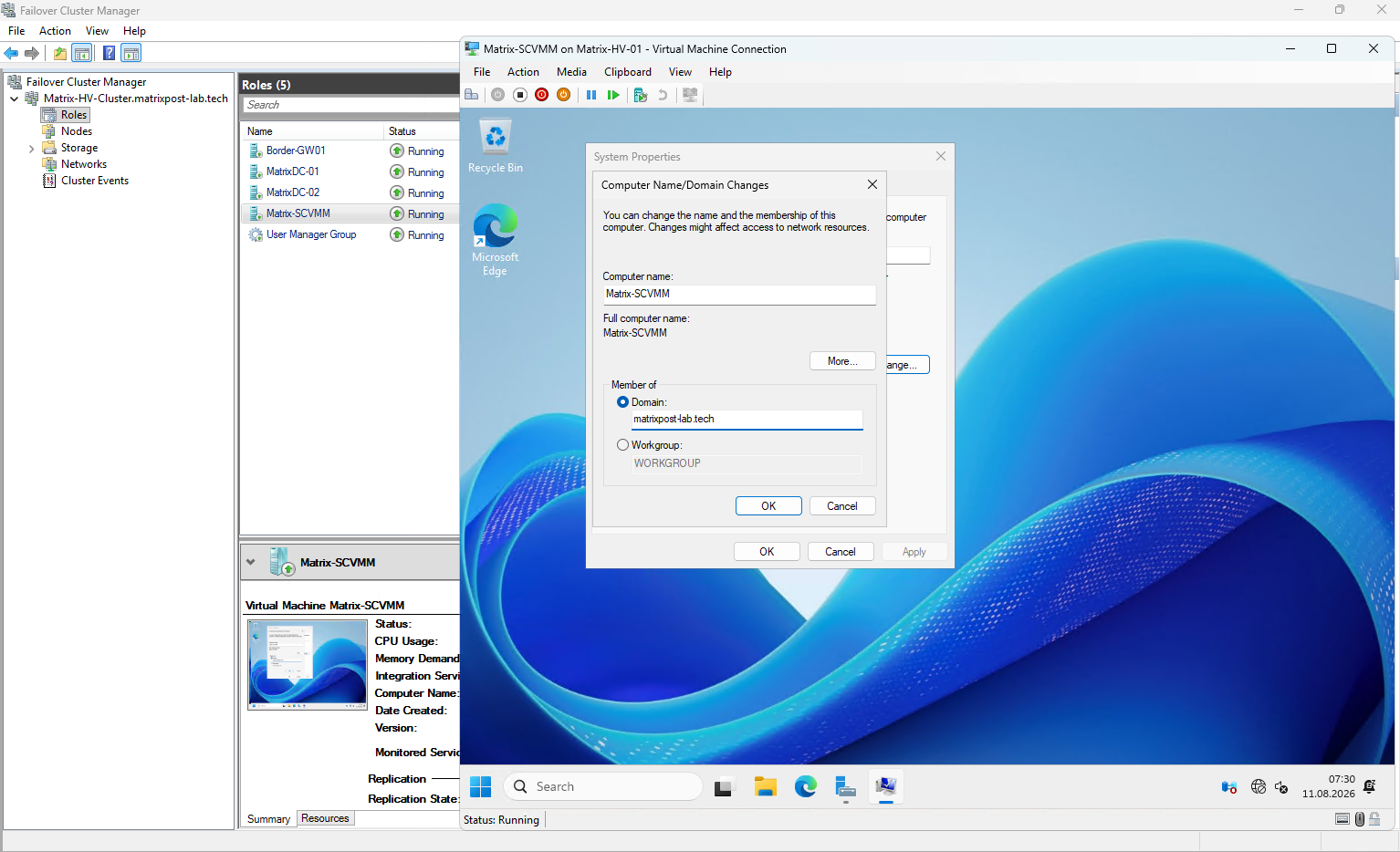
Before installing SCVMM, I will assign the server a free static IP address, configure the appropriate DNS servers, and join Matrix-SCVMM to the matrixpost-lab.tech domain.
Domain membership is required for the VMM management server and enables SCVMM to securely discover and manage our domain-joined Hyper-V hosts and cluster.
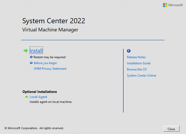
Once the installation media has been extracted and started, the System Center 2022 Virtual Machine Manager setup screen appears.
Click Install to begin installing the SCVMM management server and console.
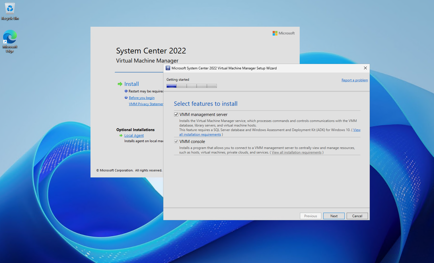
Select both the VMM management server and the VMM console. The management server provides the central SCVMM services and communicates with the managed Hyper-V hosts, while the console provides the graphical interface we will use to configure and manage the environment.
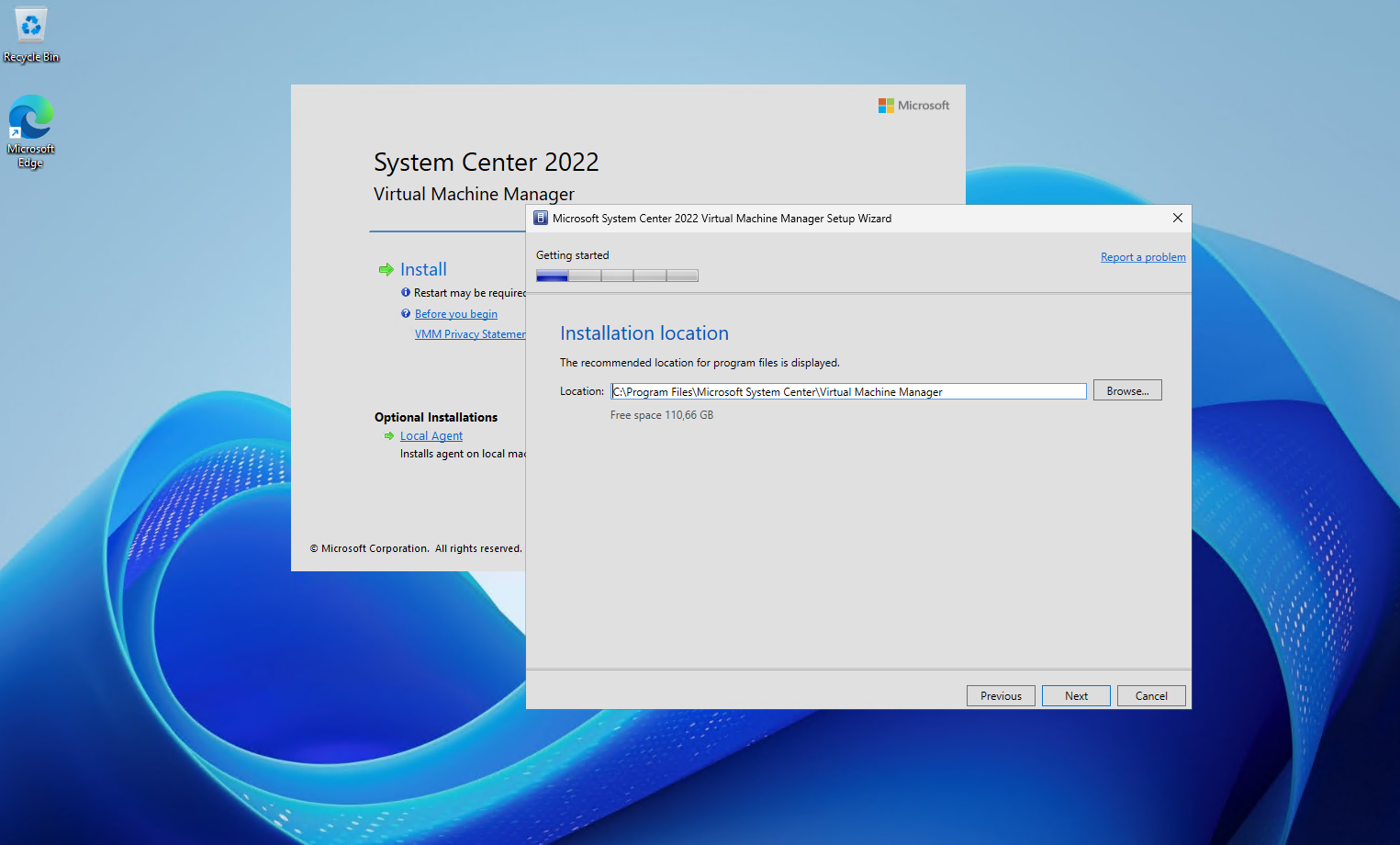
Keep the default installation location for the SCVMM program files and click Next. For our lab environment, there is no reason to change the default path.
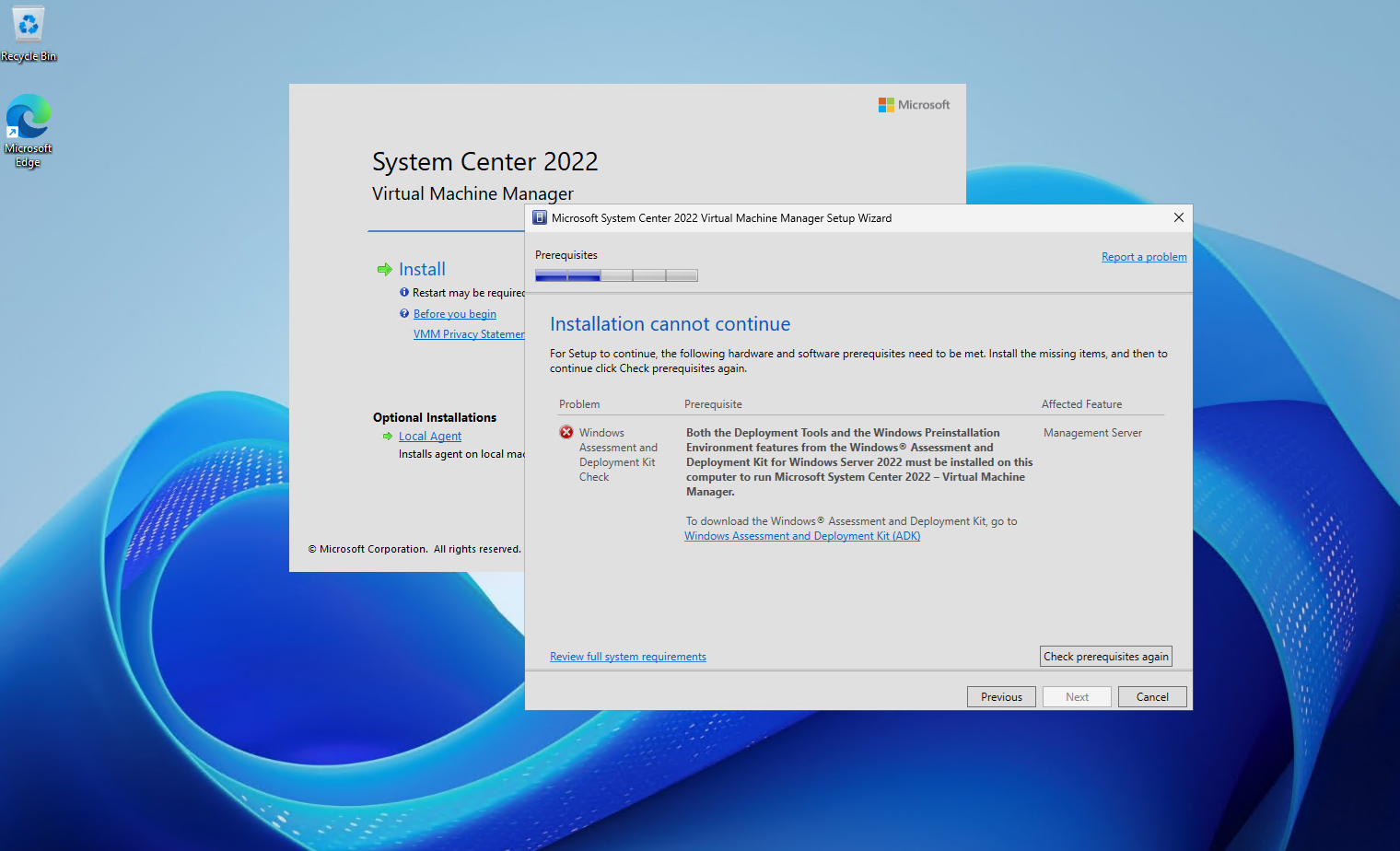
The prerequisite check detects that the required Windows Assessment and Deployment Kit (Windows ADK) components are missing. For SCVMM 2022, both the Deployment Tools and the Windows Preinstallation Environment (Windows PE) components must be installed before the setup can continue.
We therefore install the required ADK components and afterwards return to the SCVMM setup and click Check prerequisites again.
Download and start the Windows Assessment and Deployment Kit (Windows ADK) installer directly on the SCVMM server. We can keep the default installation path and continue with Next.
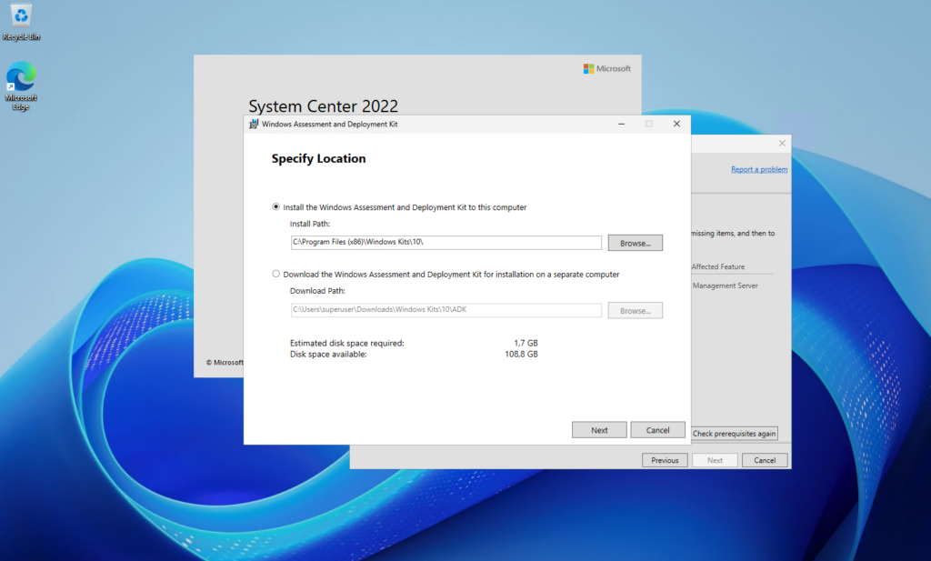
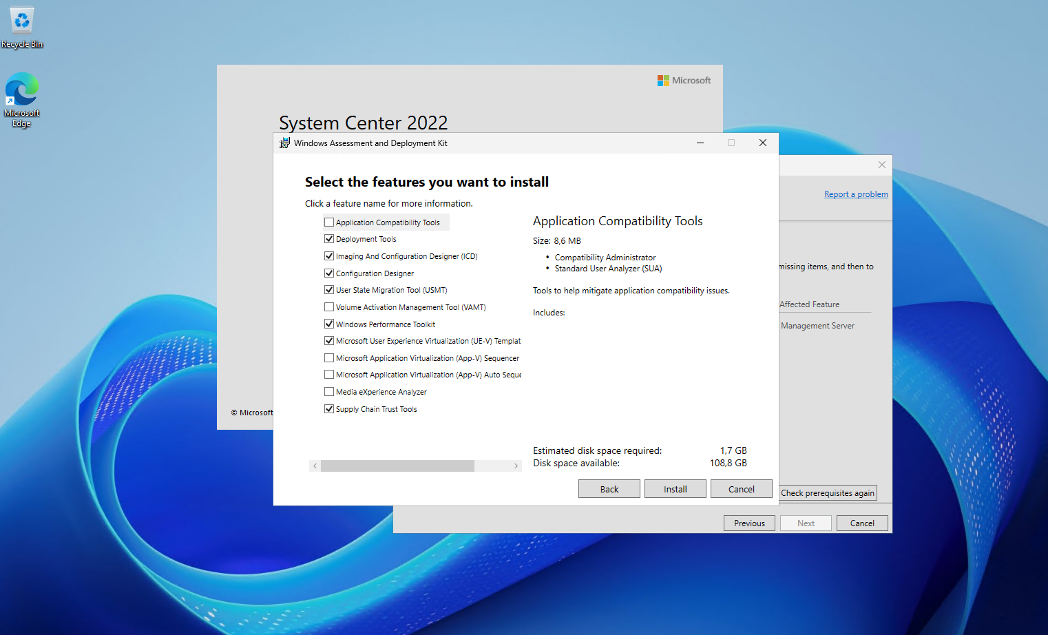
In the Windows ADK feature selection, deselect the unnecessary components and install only Deployment Tools, which is required by the SCVMM management server. Windows PE is also required, but in current ADK versions it is provided as a separate Windows PE add-on, which we will install afterwards.
Also download and install the Windows Preinstallation Environment (Windows PE) Windows PE add-on for the Windows ADK.
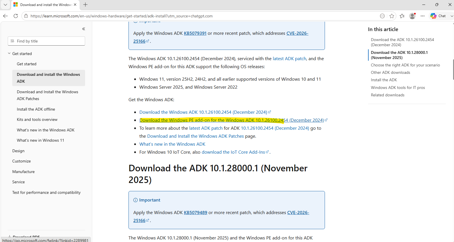
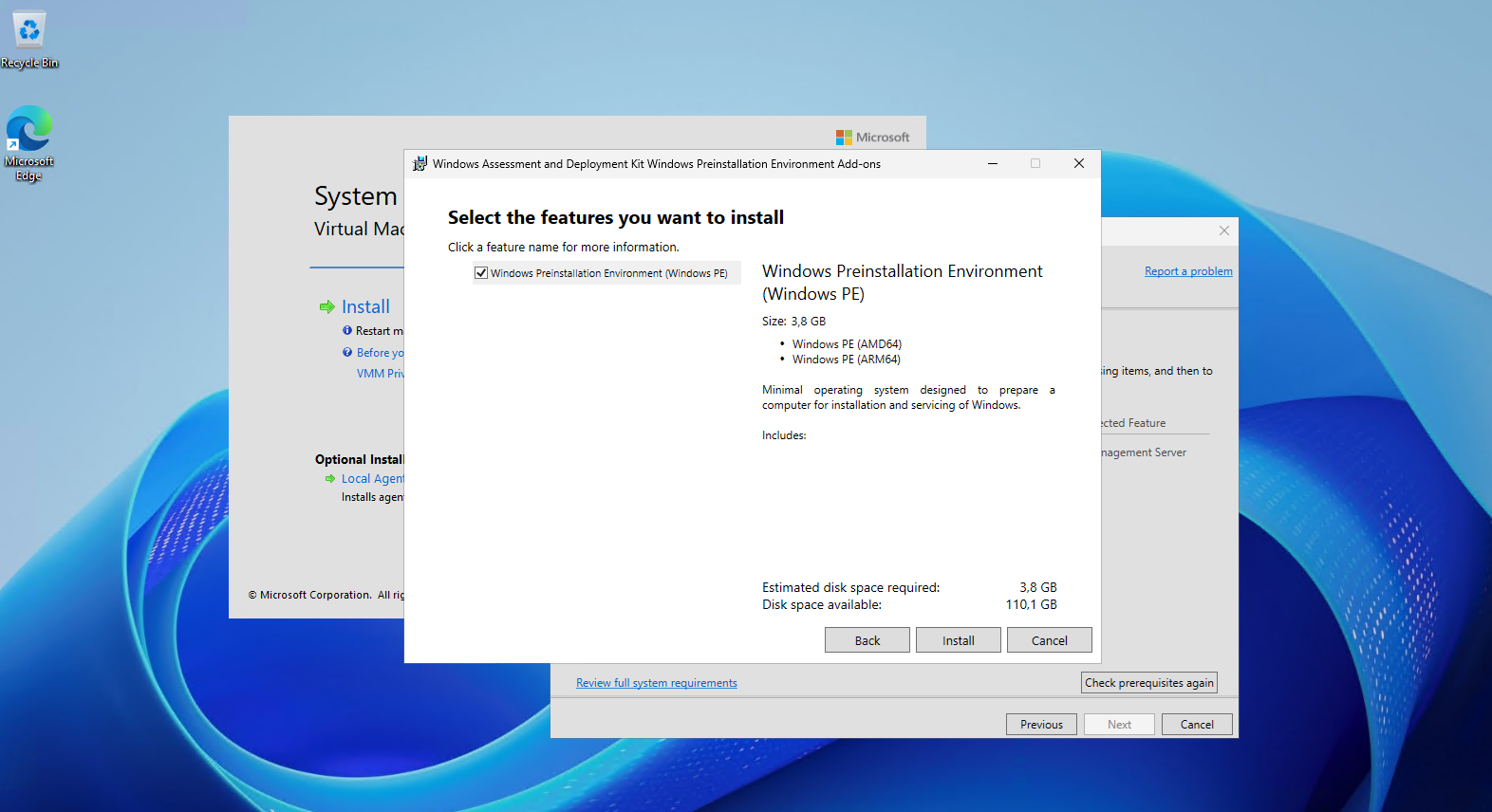
After installing the separate Windows PE add-on, the blocking prerequisite check was resolved.
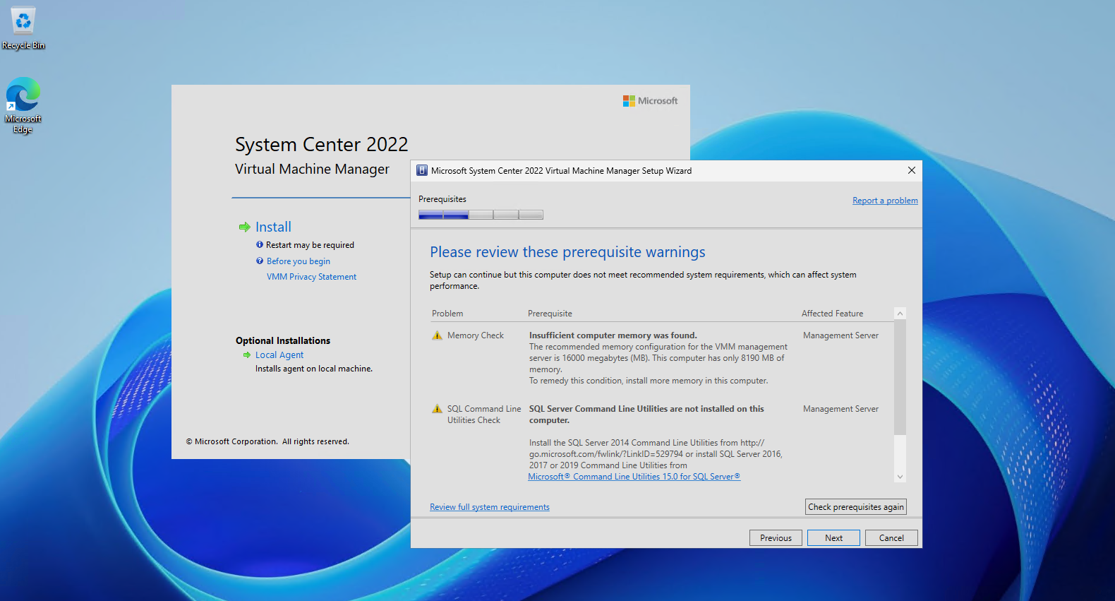
The SCVMM installer now only reports warnings about the VM having 8 GB instead of the recommended 16 GB of RAM and the missing SQL Server Command Line Utilities. For our small lab environment, we can accept these warnings and continue with the installation.
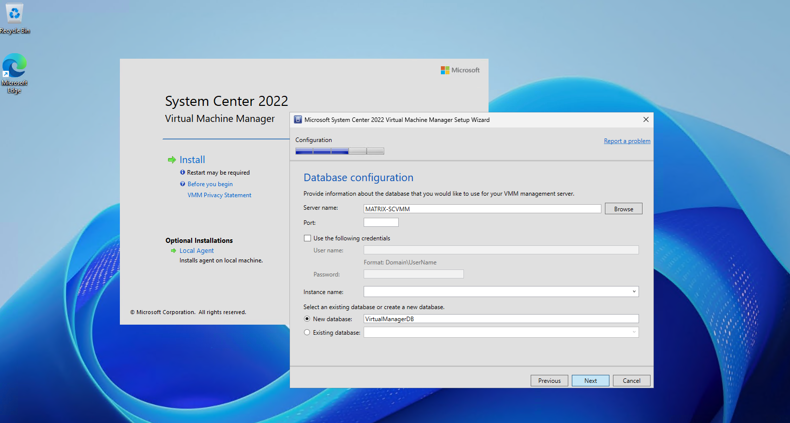
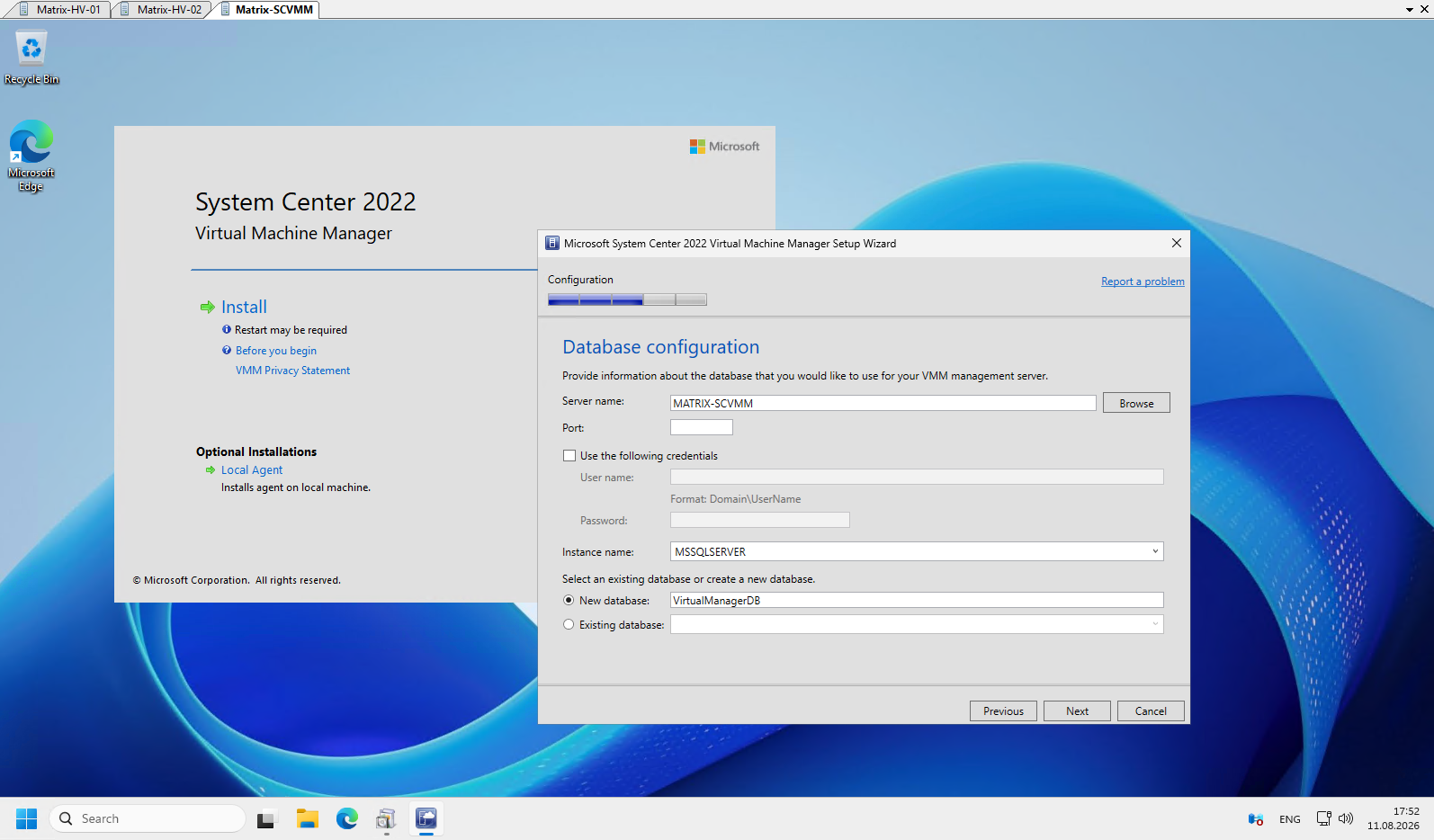
Next, we configure the SQL Server database used by SCVMM. Since SQL Server is installed locally on our MATRIX-SCVMM server, we select the local SQL Server instance and create a new database using the default name VirtualManagerDB.
Note: Before installing System Center Virtual Machine Manager (SCVMM), we first need to install a supported Microsoft SQL Server, as VMM requires a SQL database to store its configuration and management data. In our lab, we will install SQL Server locally on the
MATRIX-SCVMMserver.
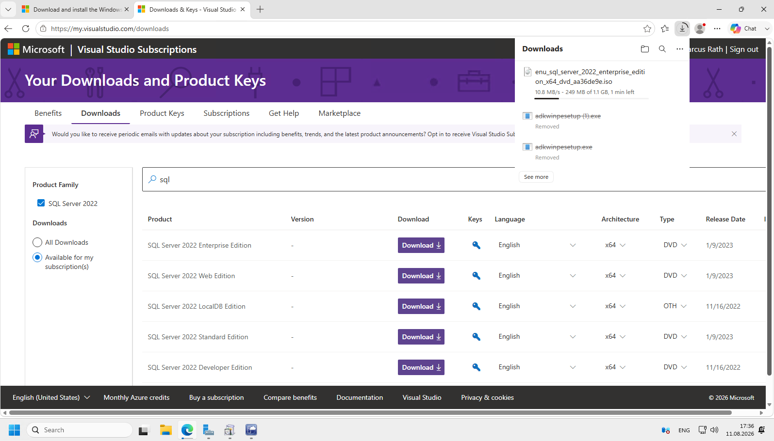
For our SCVMM 2022 lab, we will use SQL Server 2022 Standard Edition, which provides everything required for the VMM database without the additional Enterprise features. We download the x64 installation media and install SQL Server locally on our MATRIX-SCVMM server.
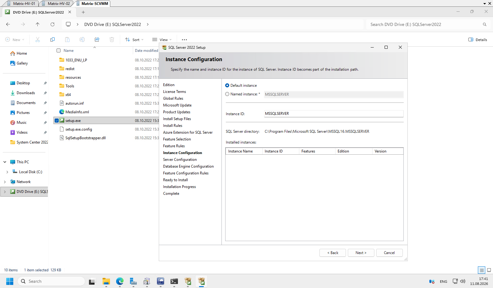
For our lab environment, we use the default SQL Server instance (MSSQLSERVER). This keeps the SCVMM database configuration simple, as no named SQL instance needs to be specified later during the VMM installation.
After installing SQL Server, the SCVMM setup now automatically detects the local MSSQLSERVER instance. We keep the default database name VirtualManagerDB and continue with the VMM installation.
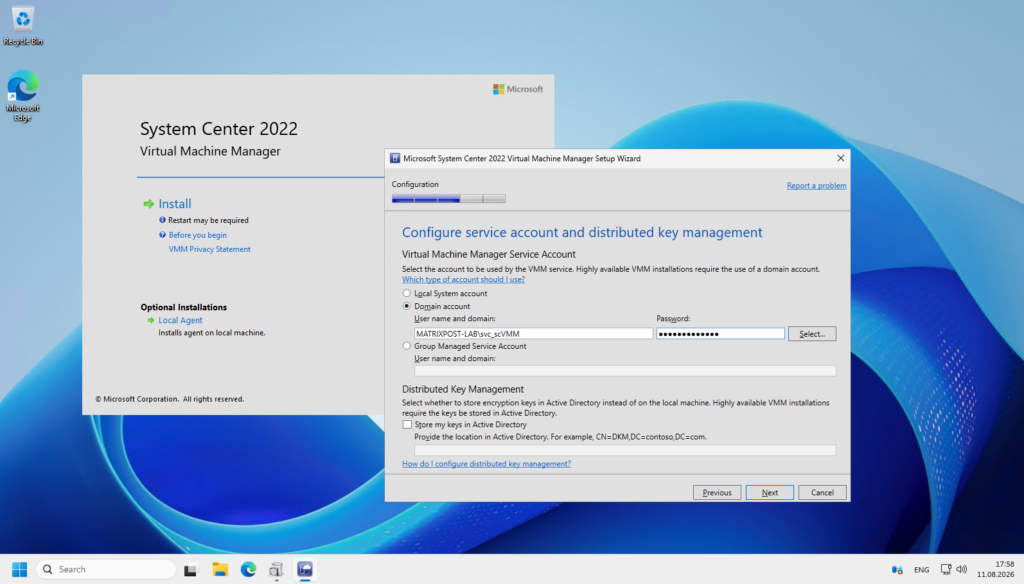
For the VMM service, we use a dedicated domain service account MATRIXPOST-LAB\svc_scVMM, which must also be added to the local Administrators group on the VMM management server.
Since our lab uses a standalone VMM management server, Distributed Key Management (DKM) is not required and the encryption keys can remain stored locally.
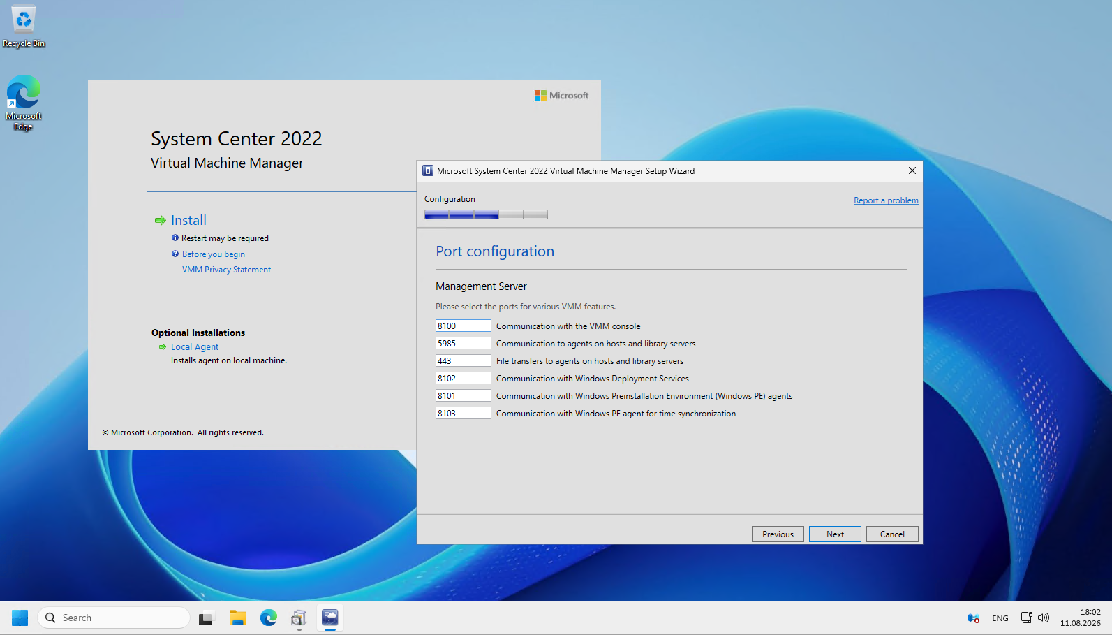
The VMM setup now displays the default communication ports used by the management server for the VMM console, Hyper-V host agents, library servers, and Windows PE components. For our lab environment, we can simply keep these default ports and continue with the installation.
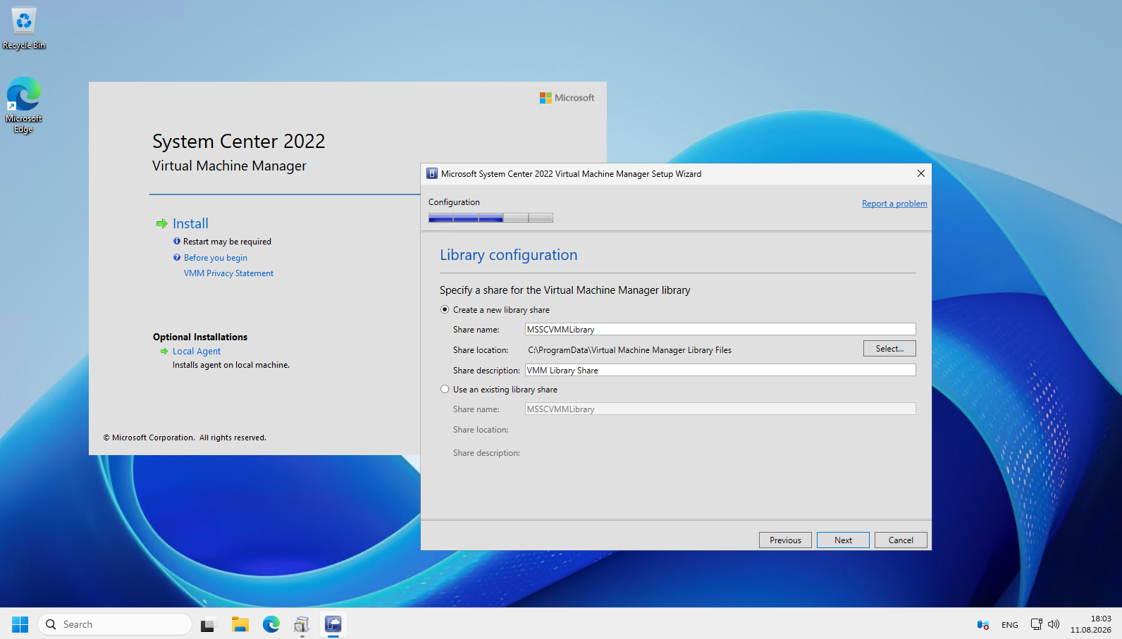
Next, VMM creates the library share, which is used to store resources such as virtual hard disks, ISO images, VM templates, and scripts for deploying and managing virtual machines. For our lab, we can keep the default MSSCVMMLibrary share and location.
Finally, review the installation summary, which shows the selected VMM components, database, service account, and configured communication ports. If everything looks correct, click Install to start the installation of the VMM management server and console.
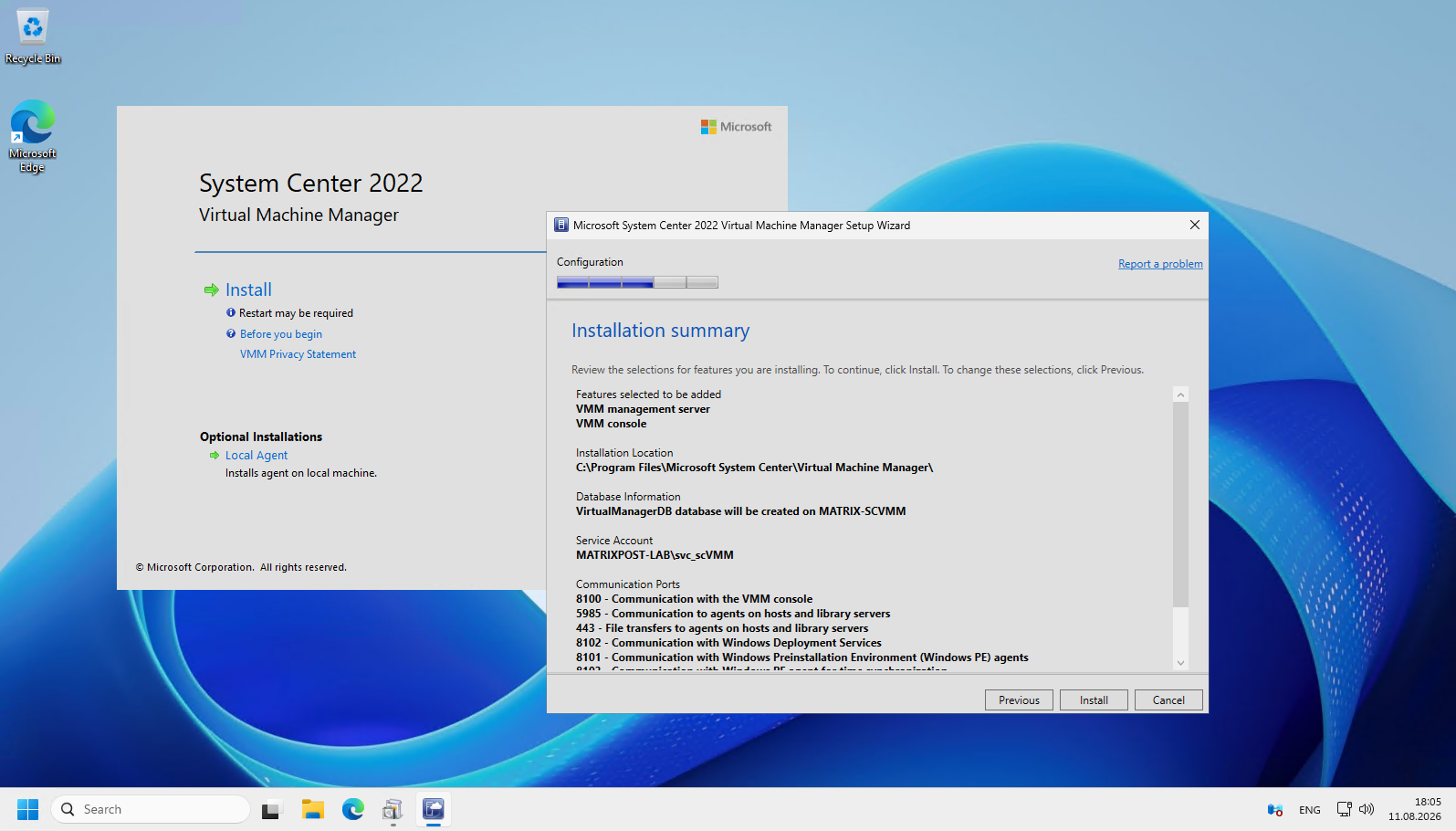
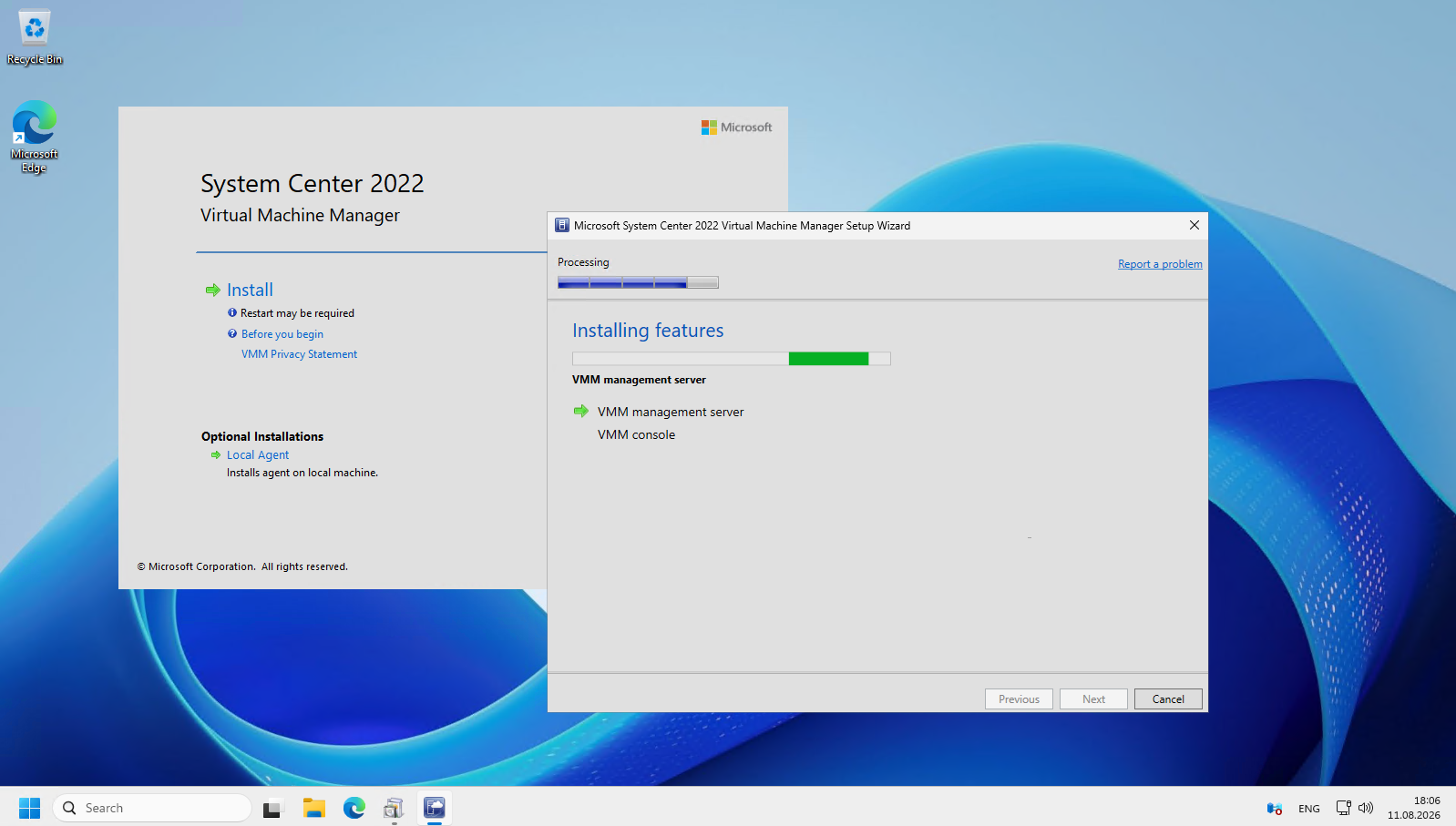
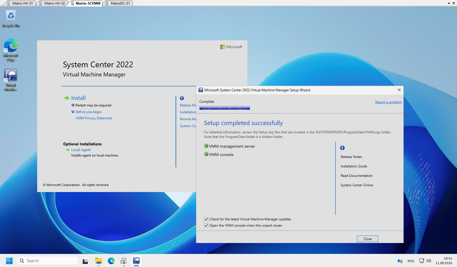
The installation now completes successfully, with both the VMM management server and VMM console installed. We can now close the setup wizard and launch the VMM console for the first time.
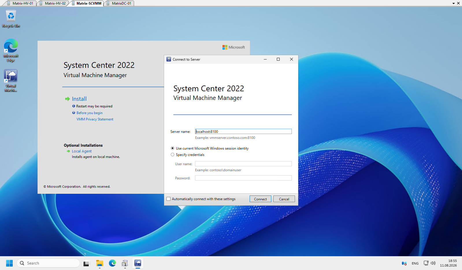
When launching the VMM console for the first time, it connects to the local VMM management server using the default port 8100.
Since the console is installed directly on our VMM server, we can keep localhost:8100 and use the current Windows session credentials.
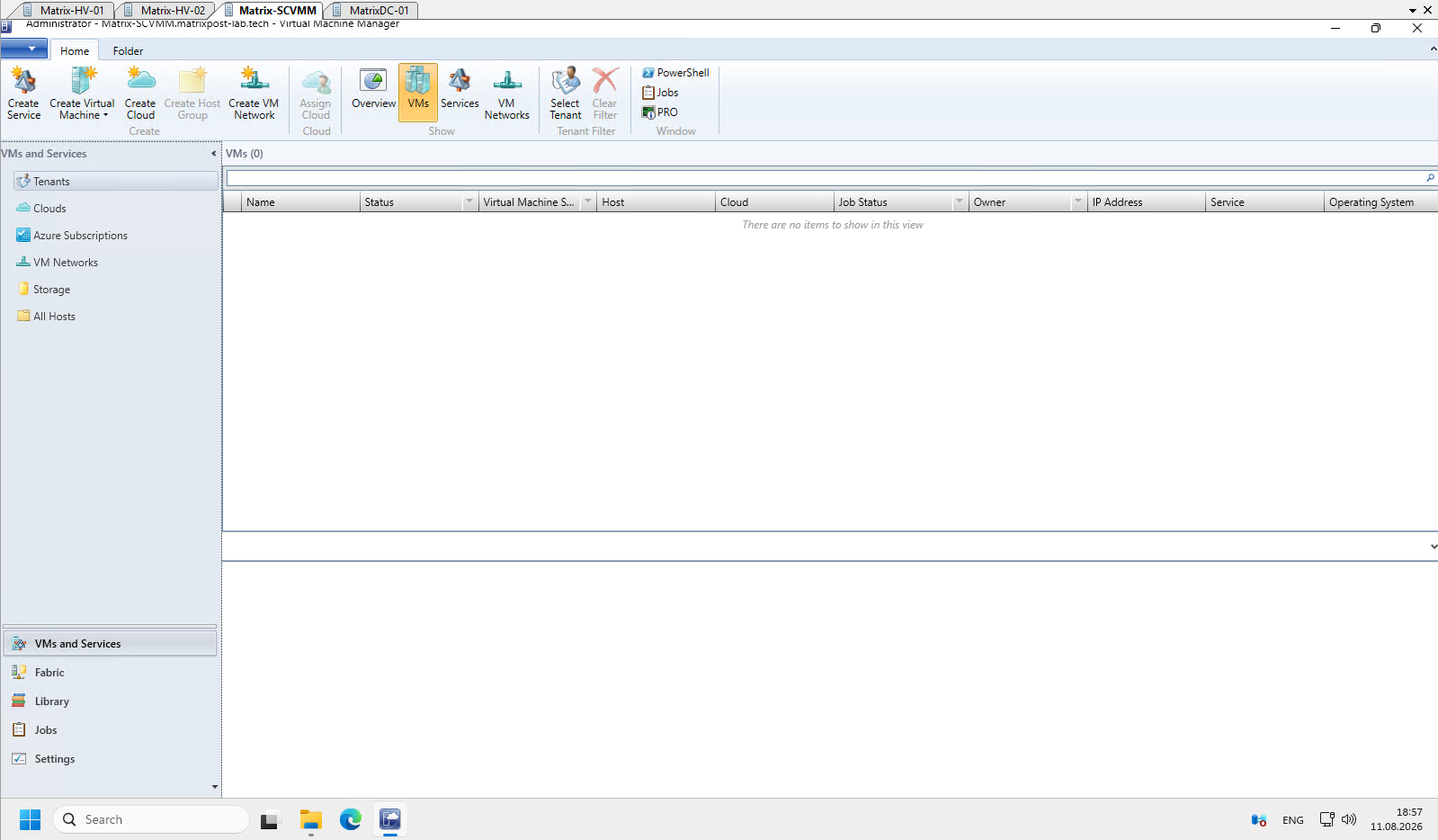
After connecting to the VMM management server, the console opens with an empty environment; next we will add our two Hyper-V hosts and the existing failover cluster to SCVMM for centralized management.
Adding the Hyper-V Failover Cluster to SCVMM
With System Center Virtual Machine Manager successfully installed, we can now start configuring our virtualization environment.
The first step is to add our existing two-node Hyper-V failover cluster to SCVMM. This allows us to centrally manage the cluster, its individual Hyper-V hosts, virtual machines, networking, and storage directly from the VMM console.
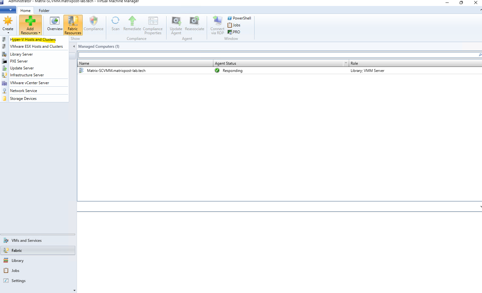
In the VMM console, switch to the Fabric workspace. From the ribbon, select Add Resources → Hyper-V Hosts and Clusters to launch the Add Resource Wizard.
The Add Resources menu also shows that SCVMM can manage VMware ESXi hosts and clusters, allowing Hyper-V and VMware virtualization resources to be managed from the same VMM environment. VMware environments are normally integrated by first adding the corresponding VMware vCenter Server to VMM.
Because our Hyper-V hosts and SCVMM server are members of the same Active Directory domain, we can use Windows domain credentials to discover and add the existing Matrix-HV-Cluster and its two nodes to VMM.
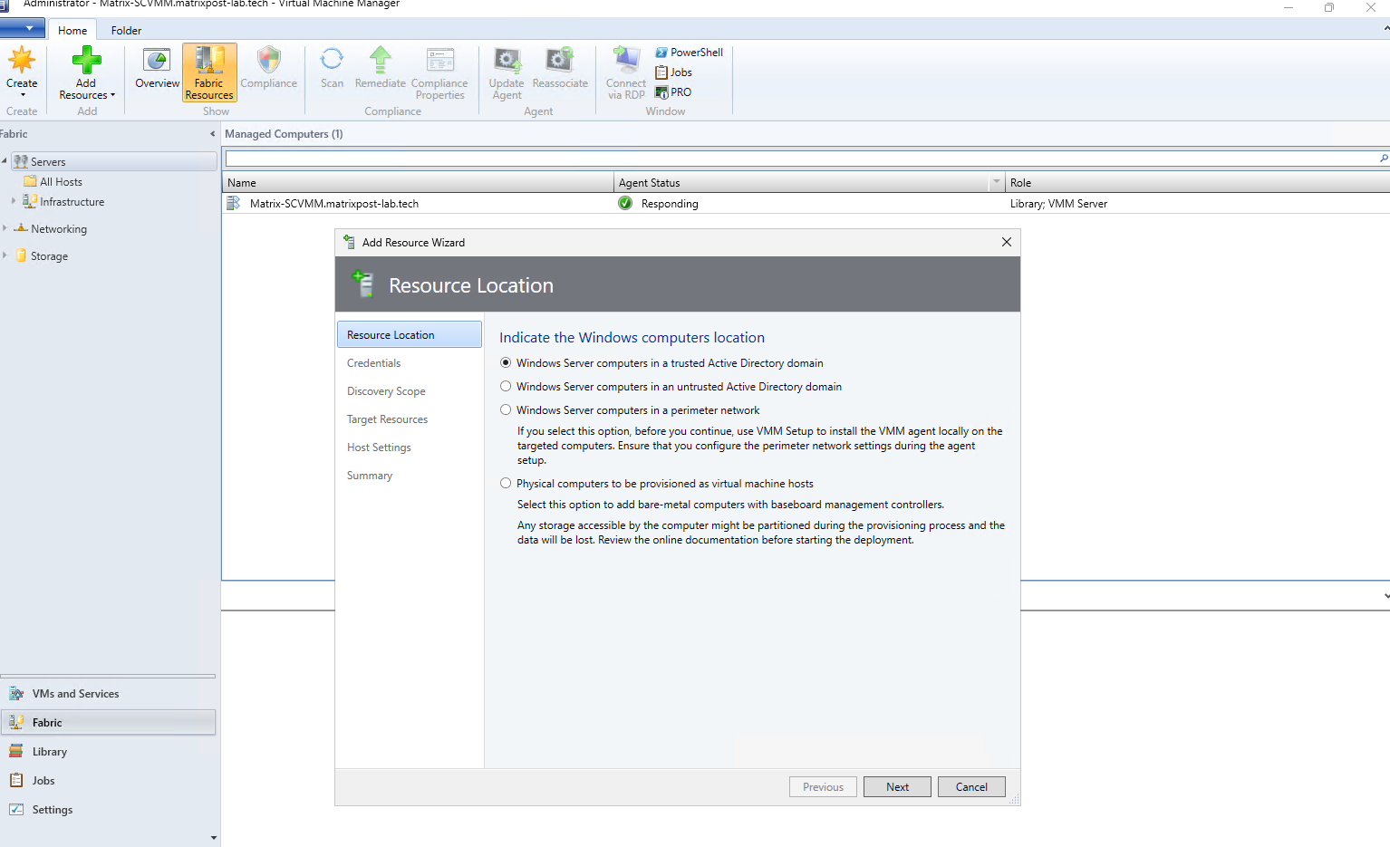
Select Windows Server computers in a trusted Active Directory domain. This allows VMM to discover and add the existing Hyper-V hosts and failover cluster using domain-based authentication.
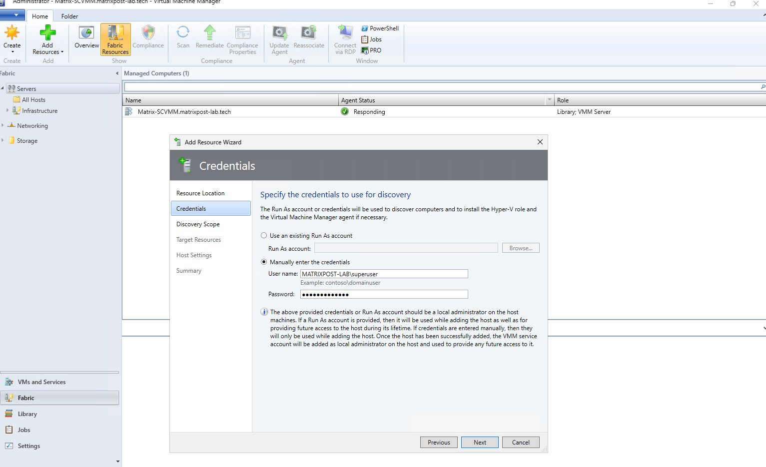
Next, specify the credentials SCVMM should use to discover and add the Hyper-V hosts. You can either select an existing Run As account or manually enter domain credentials; the account must have local administrator permissions on the Hyper-V hosts.
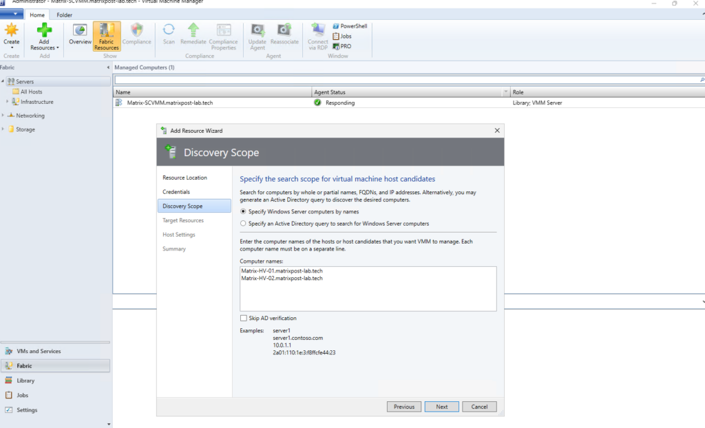
Here we specify the Hyper-V hosts that SCVMM should discover and add to its managed fabric. Since both nodes belong to our existing failover cluster, enter the FQDNs of Matrix-HV-01 and Matrix-HV-02; SCVMM will detect their cluster membership during discovery.
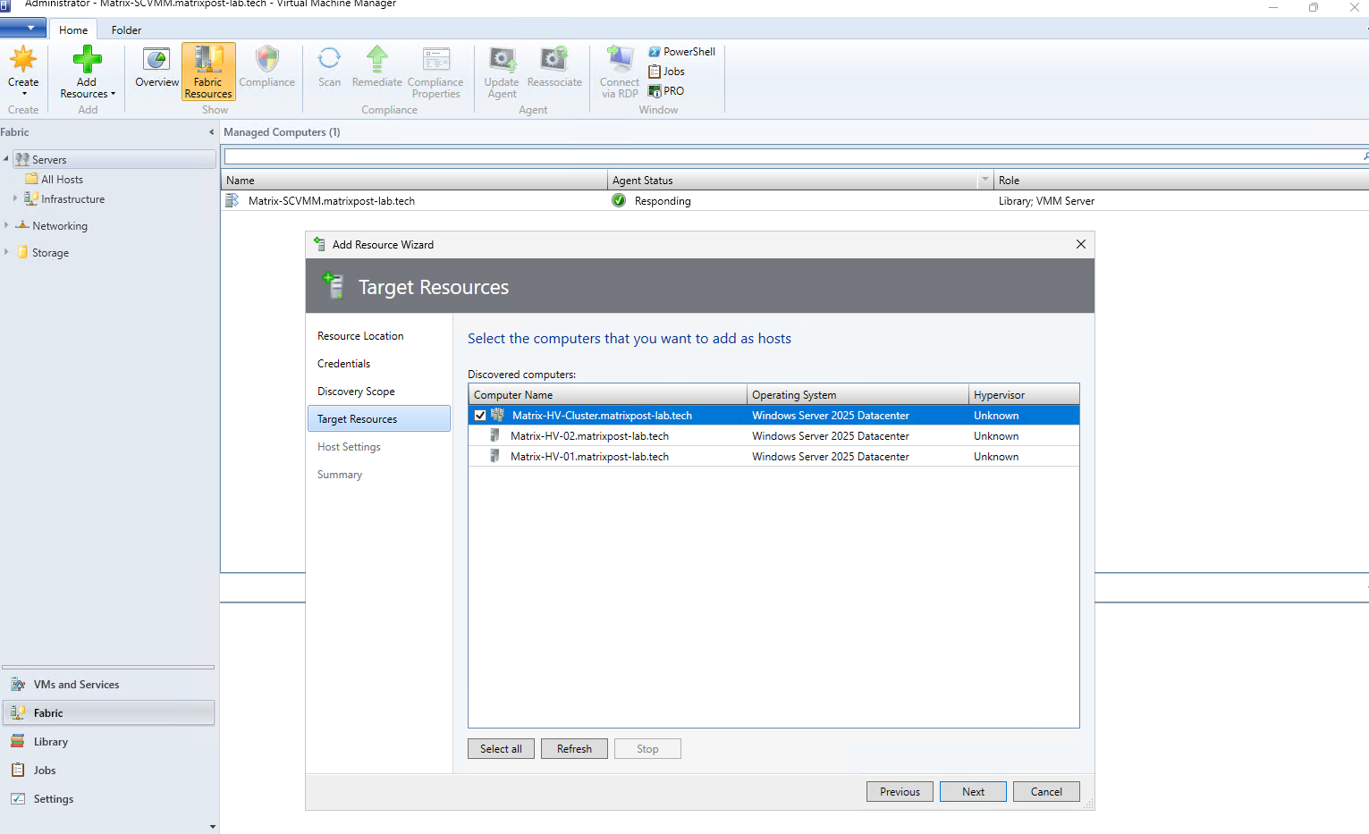
SCVMM has successfully detected that both Hyper-V hosts are members of the existing Matrix-HV-Cluster and automatically presents the cluster together with its two nodes. Select the cluster itself, which automatically includes both Hyper-V hosts, and click Next.
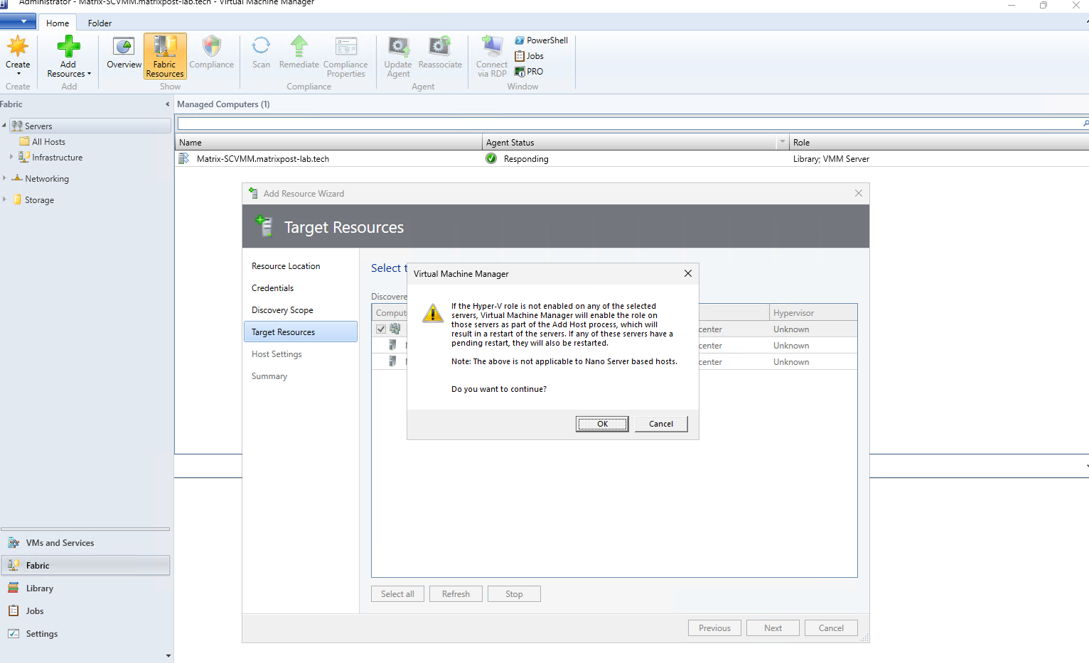
SCVMM displays a generic warning that, if the Hyper-V role is not already installed, it will automatically enable the role and restart the affected server if required. Since our two nodes are already configured as Hyper-V hosts, no role installation or restart should be necessary, so we can confirm the message with OK and continue.
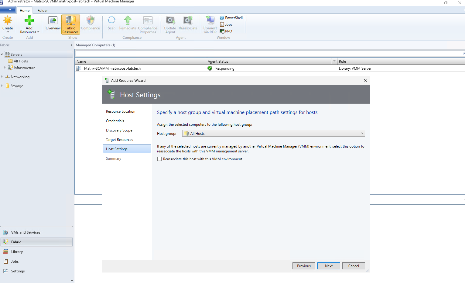
Next, assign the discovered Hyper-V cluster to an SCVMM host group. For our lab environment, we can simply keep the default All Hosts group; the Reassociate this host with this VMM environment option is only required if the hosts were previously managed by another VMM management server.
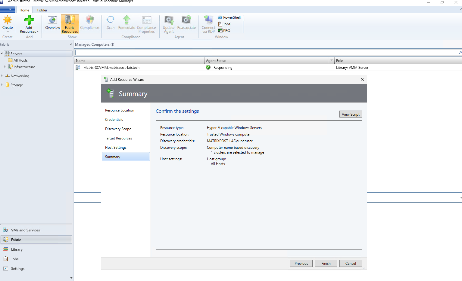
Finally, review the configuration summary before adding the cluster to SCVMM. It confirms the selected discovery credentials, computer-based discovery, the detected cluster, and its assignment to the All Hosts host group; click Finish to start the onboarding process.
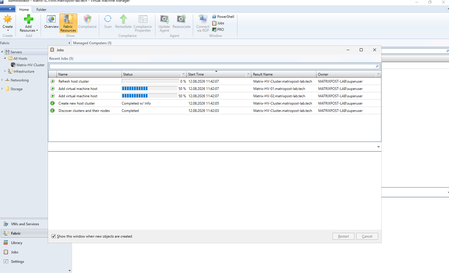
After clicking Finish, SCVMM starts a series of jobs to discover the cluster, create the corresponding host-cluster object, and add both Hyper-V nodes as managed virtualization hosts. The progress of each individual operation can be monitored directly in the Jobs window.
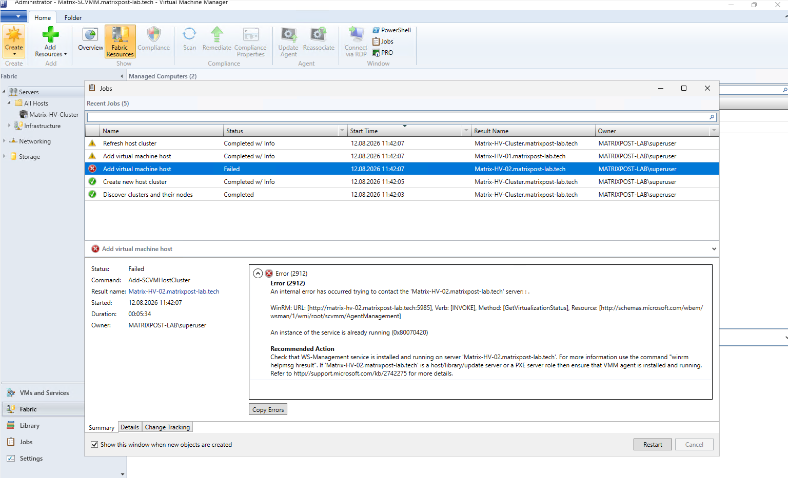
During the onboarding process, SCVMM successfully discovered the Hyper-V cluster and both nodes, but adding Matrix-HV-02 failed with Error (2912). The error indicated that SCVMM was unable to retrieve the virtualization status of the host through WinRM, while Matrix-HV-01 was added successfully.
Checking the affected host revealed that the Hyper-V Virtual Machine Management (vmms) service was stuck in the Stop Pending state. This explained why SCVMM could not communicate properly with the Hyper-V management layer and ultimately failed to add the host.
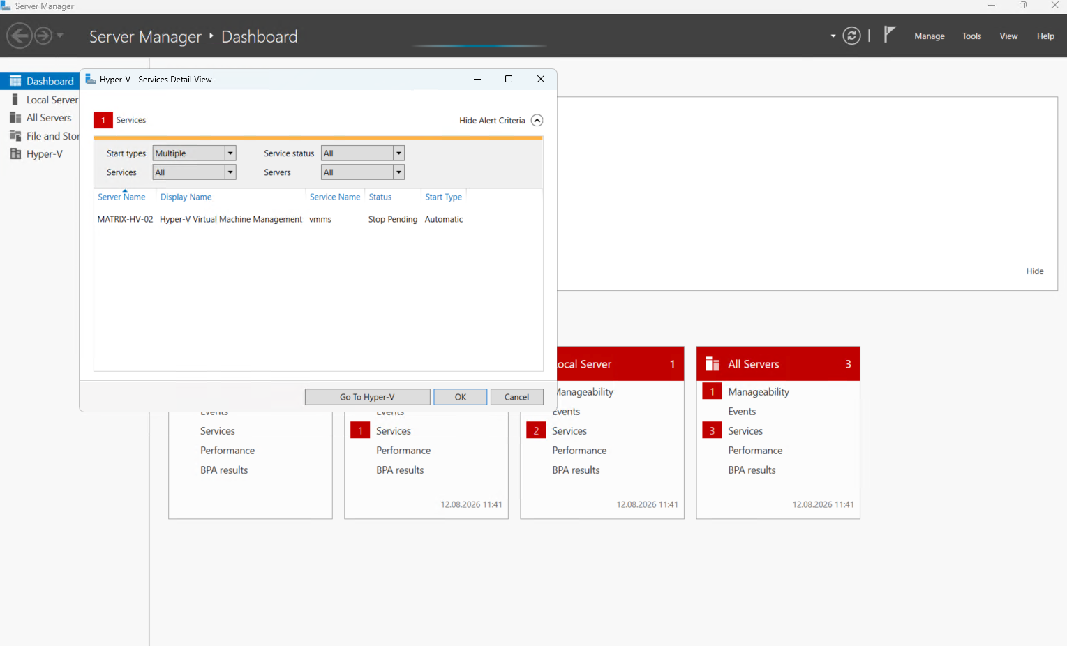
Since the VMMS service was stuck in the Stop Pending state and could not be restarted normally, we rebooted Matrix-HV-02 to bring the service back online. Afterwards, we selected the failed SCVMM job and clicked Restart to retry adding the Hyper-V host.
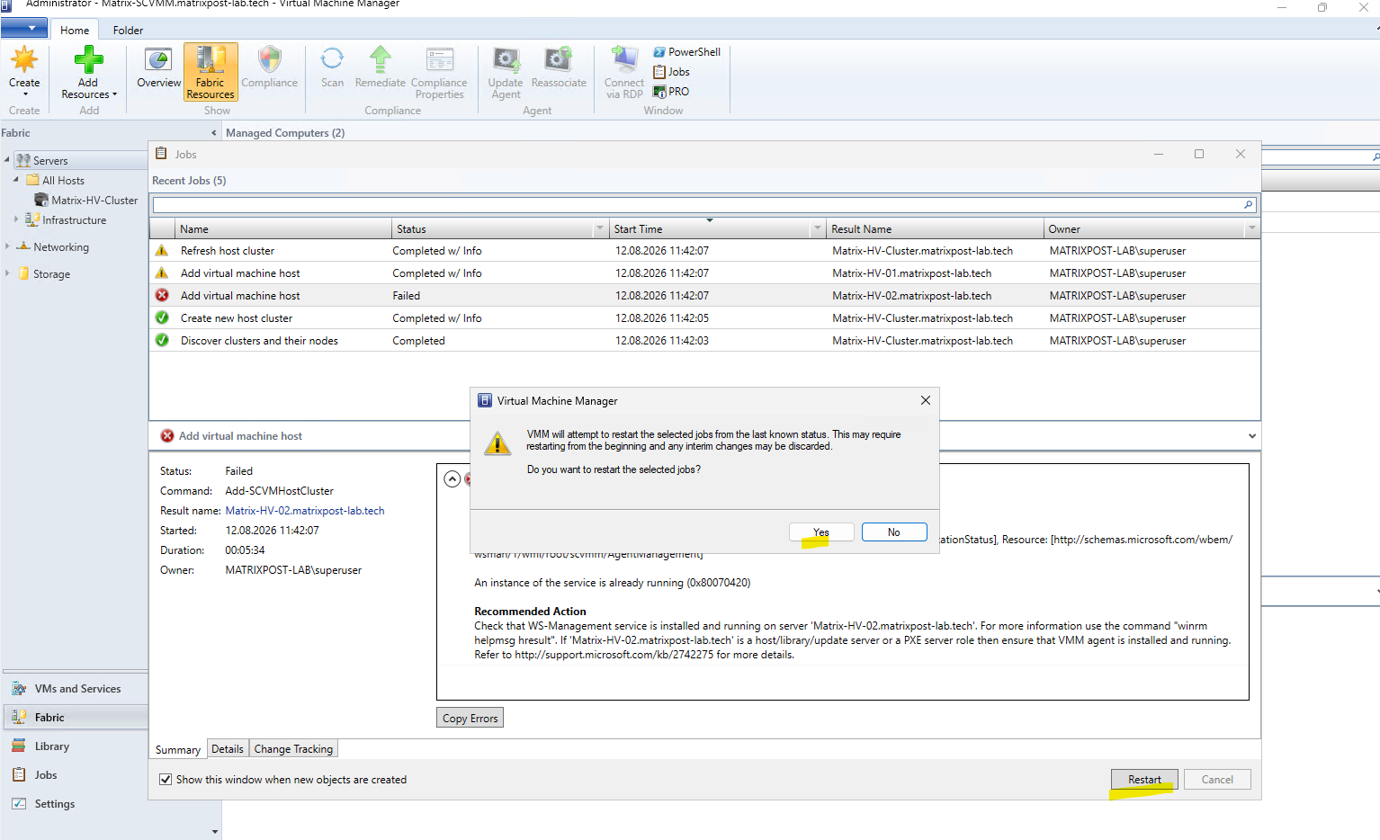
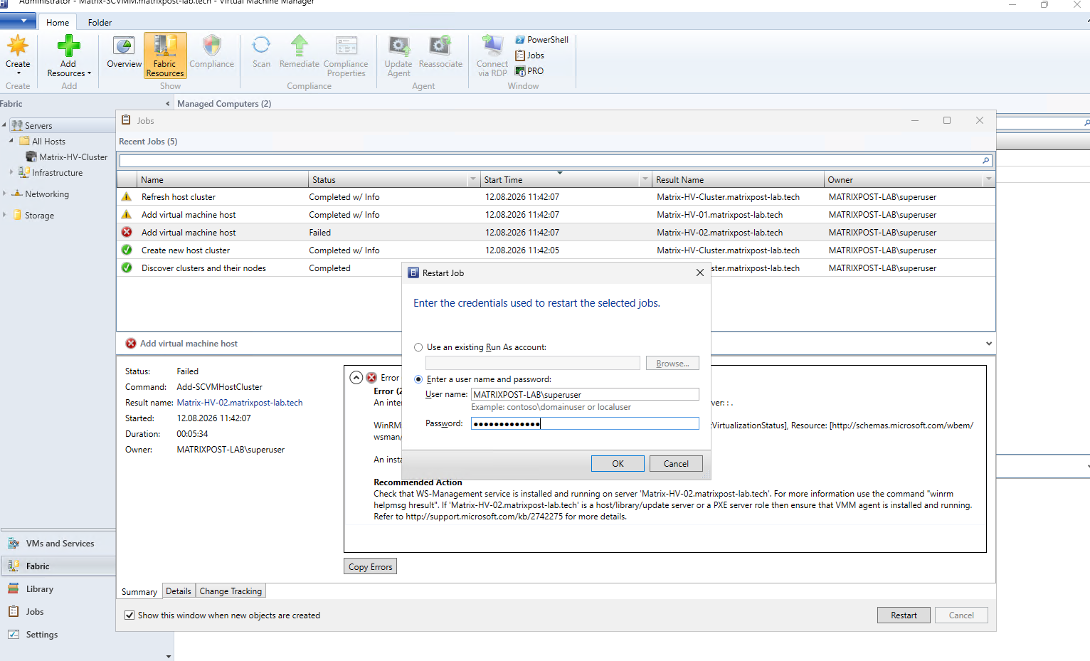
When restarting the failed job, SCVMM prompts again for credentials with sufficient administrative permissions on the Hyper-V host. We entered our domain administrator credentials and clicked OK to retry the onboarding of Matrix-HV-02.
After restarting the job, SCVMM resumed the onboarding of Matrix-HV-02 and progressed normally this time. This confirms that the previous failure was resolved after rebooting the host and restoring the VMMS service to a healthy state.
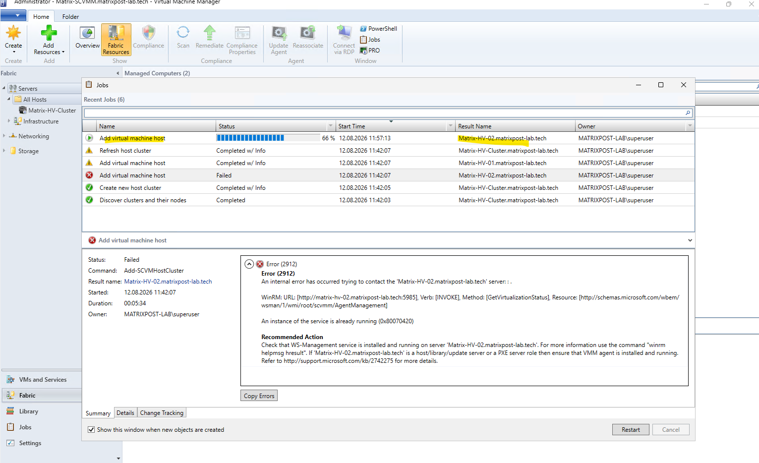
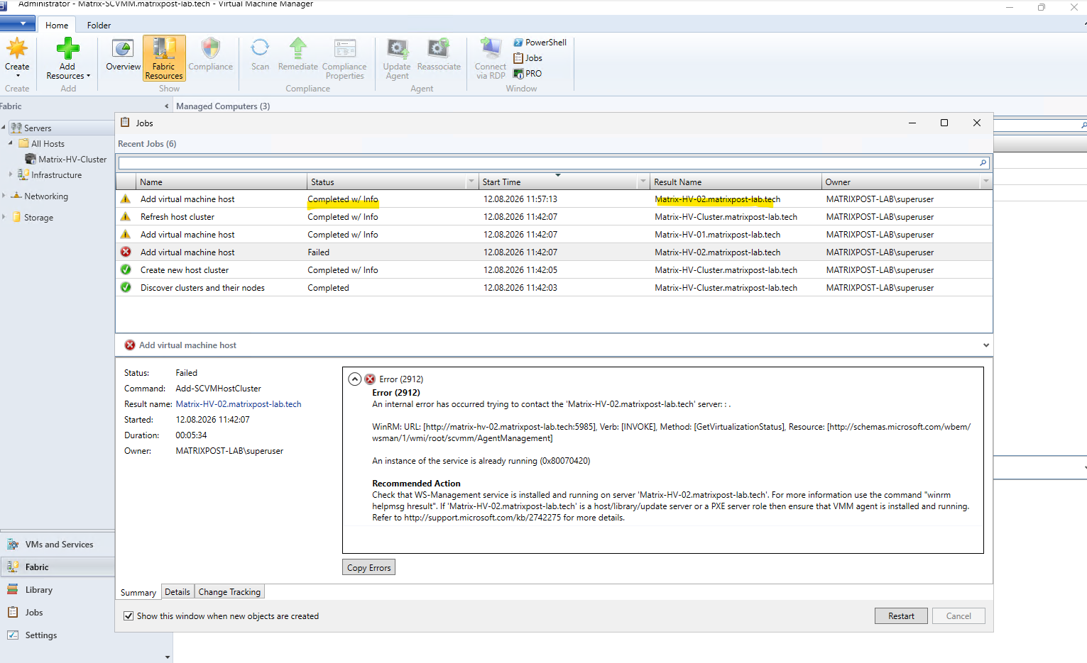
Finally, the restarted Add virtual machine host job for Matrix-HV-02 completed successfully. Both Hyper-V nodes are now managed by SCVMM, completing the onboarding of our two-node Matrix-HV-Cluster.
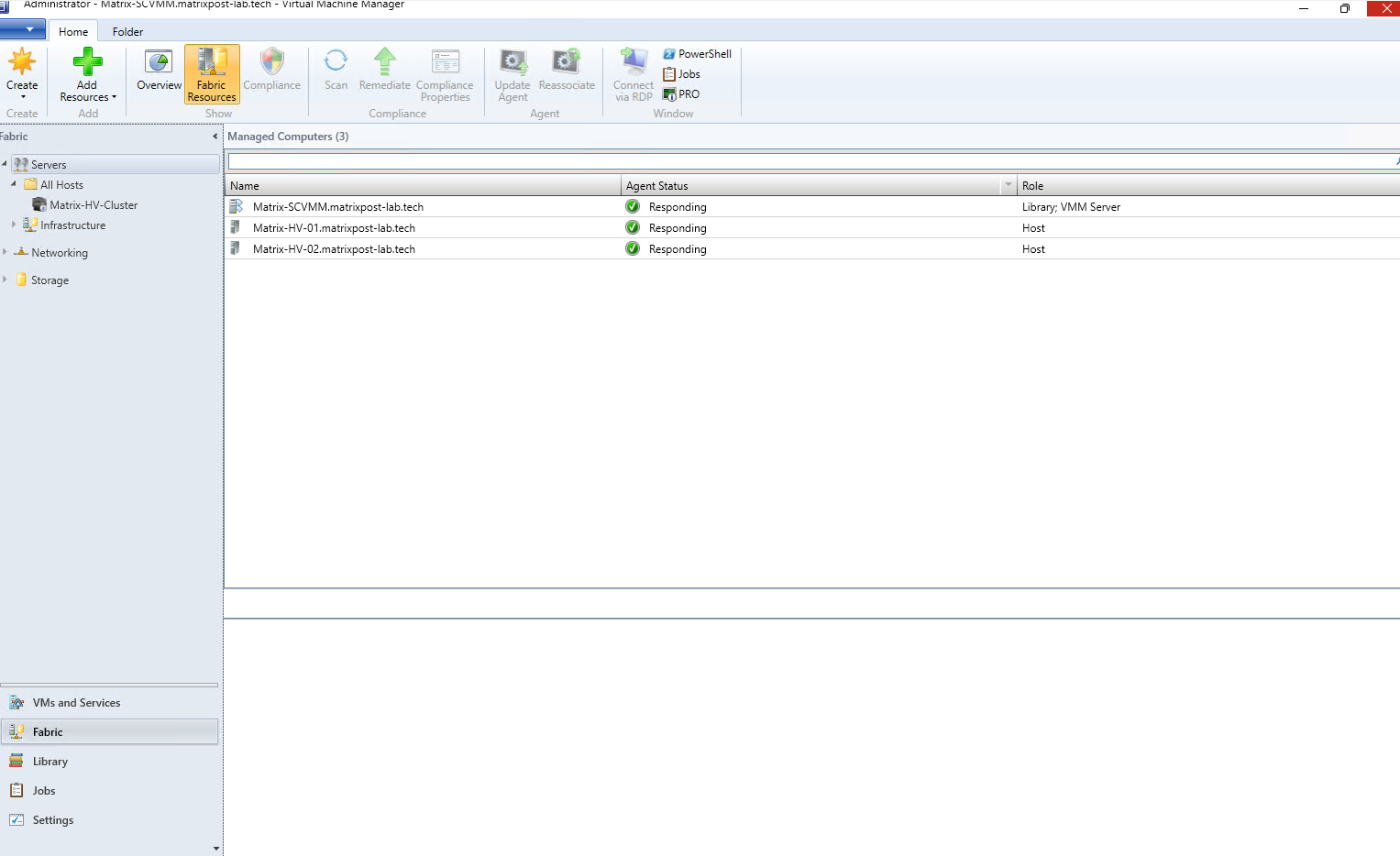
As a final verification, under Fabric → Servers → All Hosts, we can now see both Matrix-HV-01 and Matrix-HV-02 registered as Hyper-V hosts. Both nodes report an Agent Status of Responding, confirming that SCVMM can successfully communicate with and manage the complete two-node cluster.
Managing the Hyper-V Cluster and Virtual Machines in SCVMM
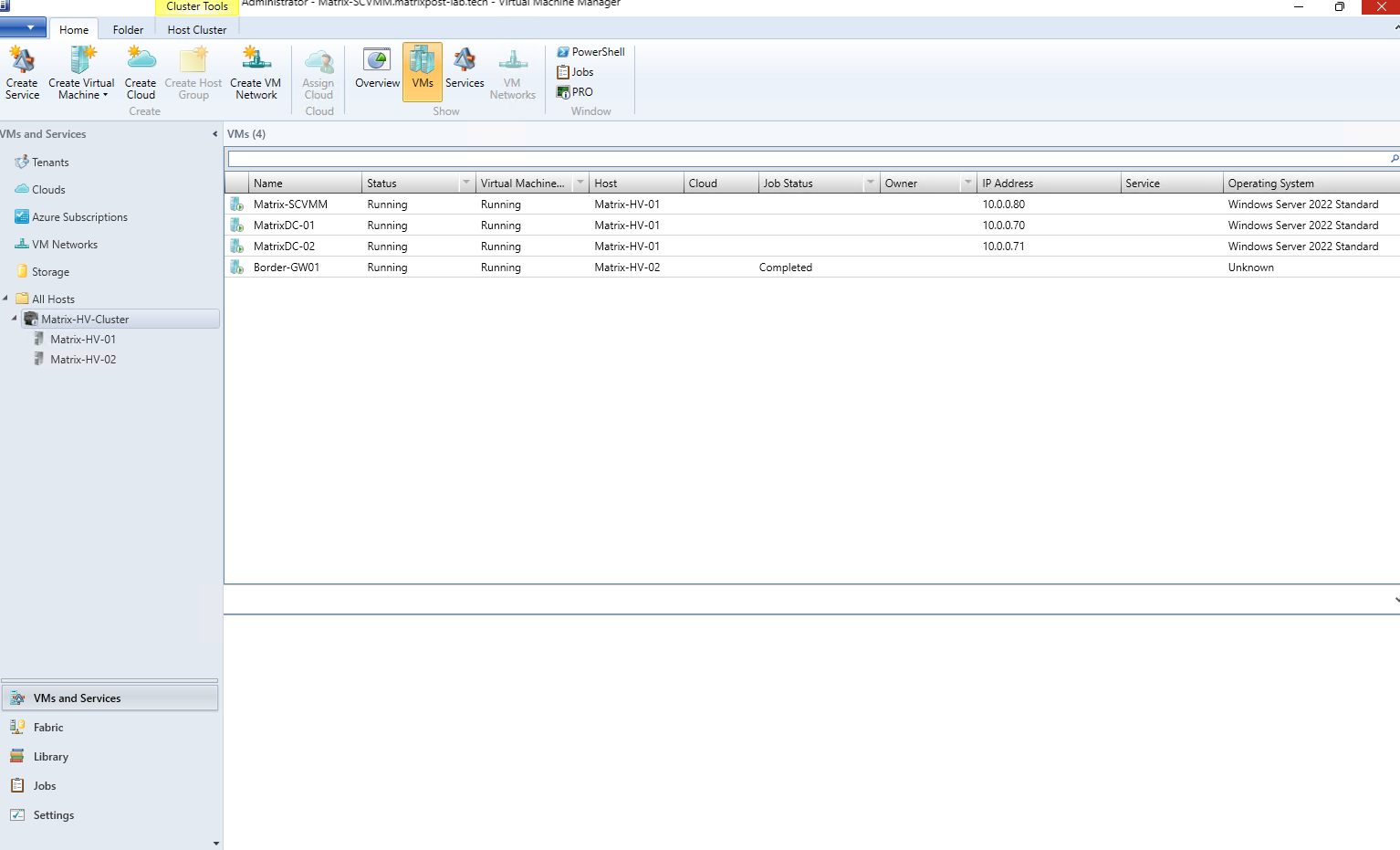
With our two-node Hyper-V failover cluster successfully added to SCVMM, we can now switch to the VMs and Services workspace and take a look at the resources discovered from the existing environment.
SCVMM automatically discovers the virtual machines already registered with the failover cluster and brings them under centralized management, allowing us to manage the VMs, their placement, availability, and lifecycle directly from the VMM console.
In our lab, all four existing virtual machines are now visible in SCVMM, distributed across Matrix-HV-01 and Matrix-HV-02. From this point on, we can centrally manage both the Hyper-V cluster and its virtual machines through SCVMM.
Configuring Hyper-V Networking in SCVMM
Now that the Hyper-V cluster and its virtual machines are managed by SCVMM, we can take a closer look at how SCVMM represents and manages the existing network configuration.
Unlike Hyper-V Manager, SCVMM introduces additional abstraction layers such as Logical Networks, Network Sites, VM Networks, and Logical Switches, allowing network configuration to be standardized across all hosts in a cluster.
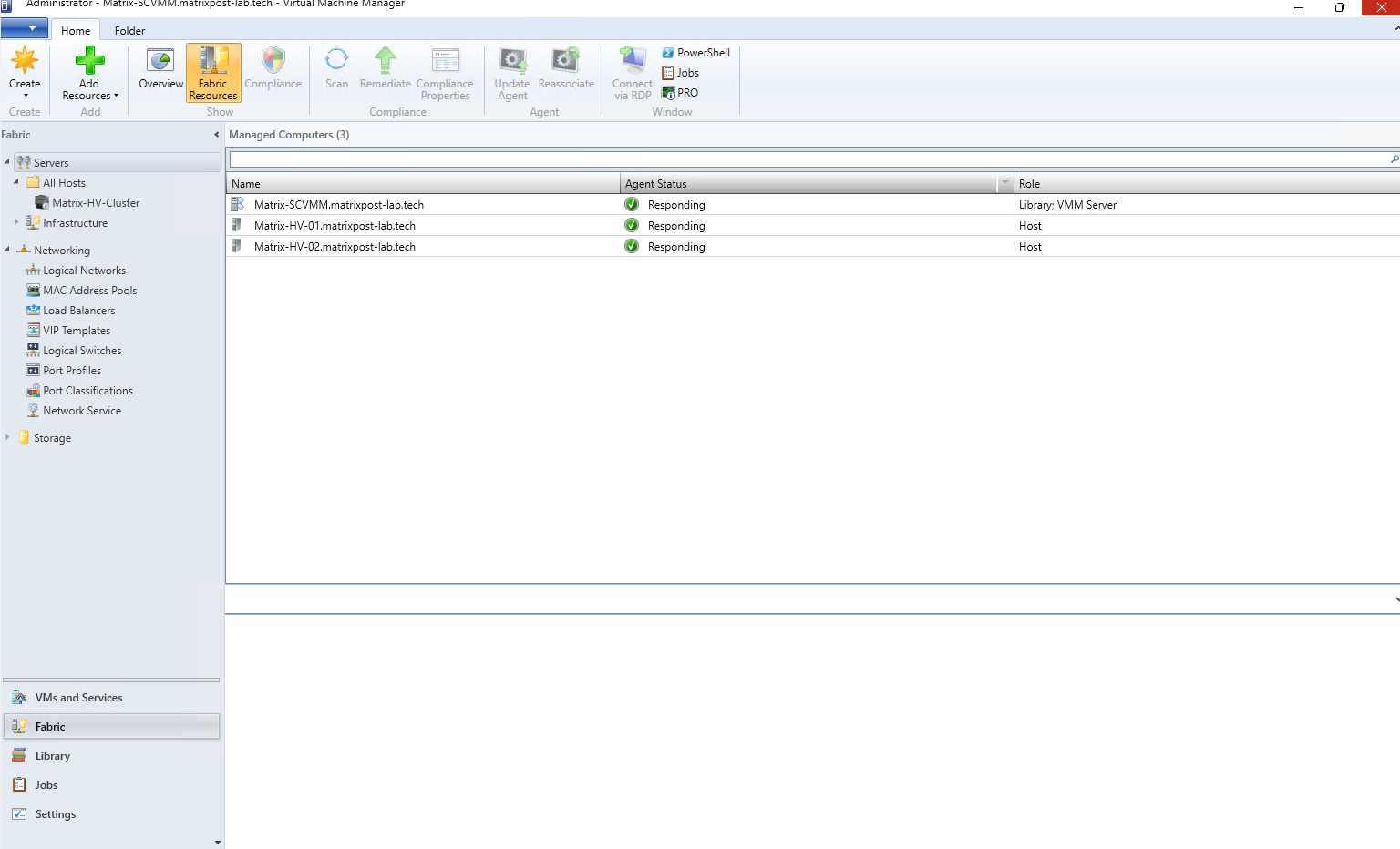
Under Fabric → Networking, SCVMM exposes the main building blocks used for centralized network management, including Logical Networks, Logical Switches, Port Profiles, and Port Classifications.
Configuring Logical Networks in System Center Virtual Machine Manager
After adding the Hyper-V cluster and its hosts to SCVMM, we can continue with the network configuration.
Navigate to Fabric → Networking → Logical Networks, where SCVMM already discovers the existing Hyper-V virtual switches (vSwitch-MGMT and vSwitch-VM) from our hosts.
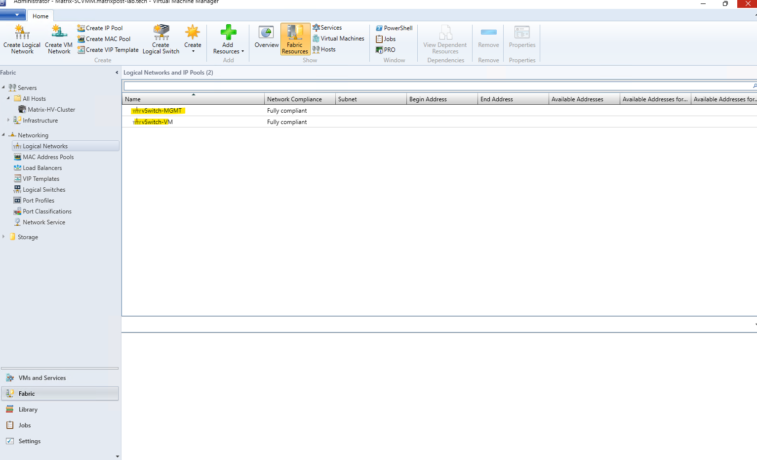
Logical Networks provide an abstraction of the physical network infrastructure and allow us to centrally define which networks, VLANs, and IP subnets are available to the managed Hyper-V hosts.
Since the Hyper-V networking was already configured before adding the cluster to SCVMM, we do not need to create another network at this point.
SCVMM has discovered the existing vSwitch-MGMT and vSwitch-VM configuration, allowing us to continue using the same physical adapters and virtual switches while managing the environment centrally through SCVMM.
Although SCVMM automatically discovers the existing Hyper-V virtual switches when the hosts are added, it does not automatically translate the complete network configuration into SCVMM network sites. As shown below, no IP subnets or VLANs are defined for the discovered logical network. These higher-level network definitions must be configured separately in SCVMM if we want to centrally model and manage the physical network topology.
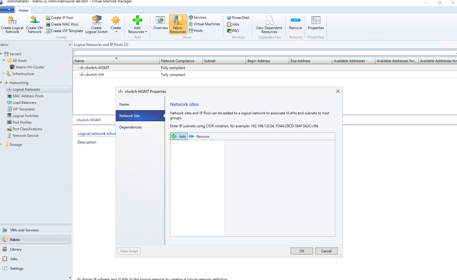
Click Add under Network Site. There we can define a site for the Hyper-V host group and associate our management/internal network with its IP subnet 10.0.0.0/24 and VLAN 10.
This doesn’t create another physical adapter or virtual switch, it simply tells SCVMM what network is actually available through the existing infrastructure.
For simplicity, although the management network uses its own dedicated
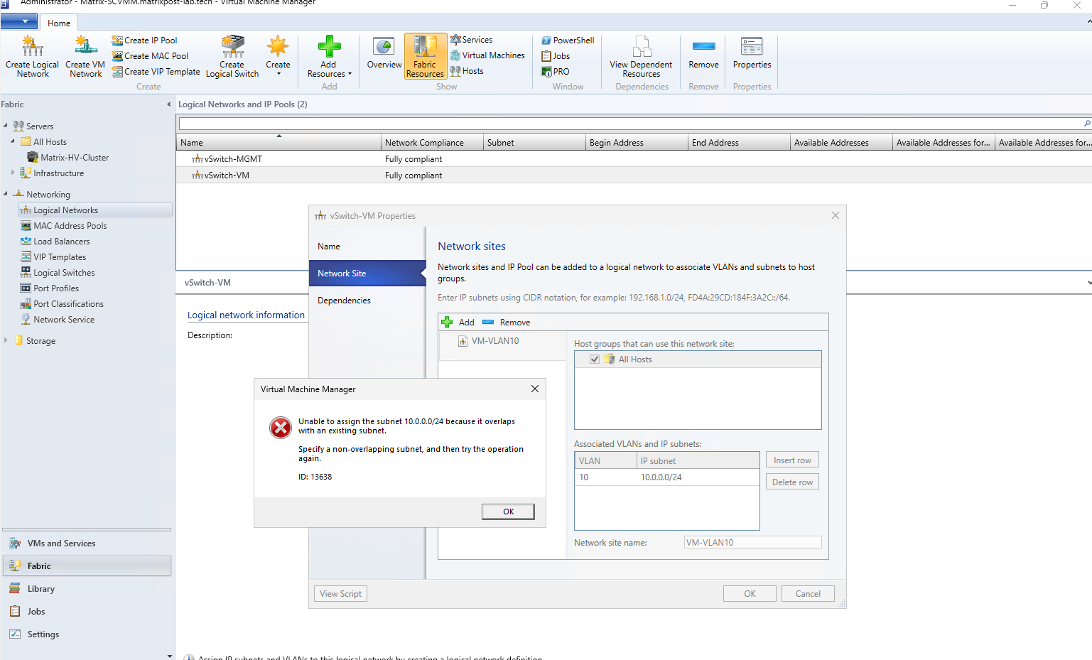
vSwitch-MGMTand dedicated physical network adapters in a SET configuration, both the management network and the internal VM network use the same10.0.0.0/24subnet and VLAN 10 in my lab.However, as we can see below, SCVMM does not support assigning the same IP subnet to two separate Logical Networks. We therefore need to separate the VM network by moving it to a different subnet and VLAN, which in turn requires either a router/firewall VM to route between the networks or inter-VLAN routing on the physical network infrastructure.
On Hyper-V itself, however, using the same subnet and VLAN across separate virtual switches and dedicated physical adapters is fully supported and works without any problems.
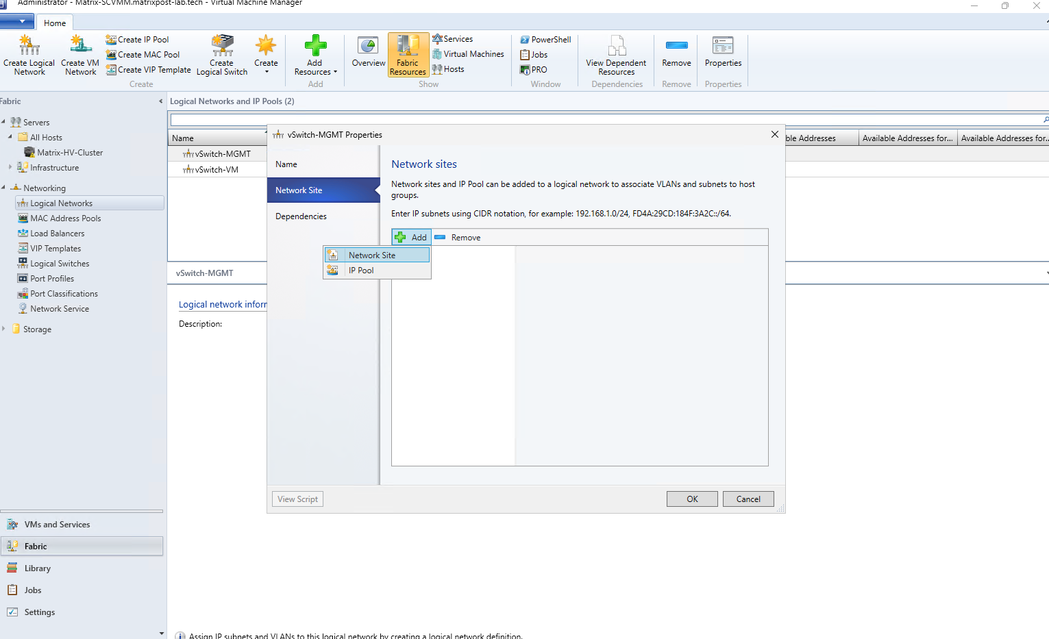
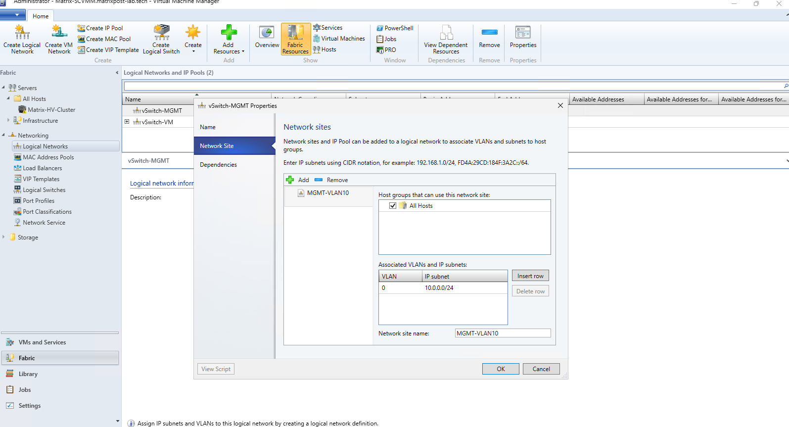
Because the physical network adapters used by vSwitch-MGMT are connected to switch access ports for VLAN 10, the Hyper-V hosts must send the management traffic untagged. Therefore, we set the VLAN assignment of the MGMT-VLAN10 network site to VLAN 0 (untagged) and for the subnet we use 10.0.0.0/24.
The Network Site tells SCVMM that this VLAN/subnet combination is physically available to the hosts belonging to the selected host group. We can keep the automatically generated site name
vSwitch-MGMT_0, or rename it to something more descriptive such asMGMT-VLAN10.
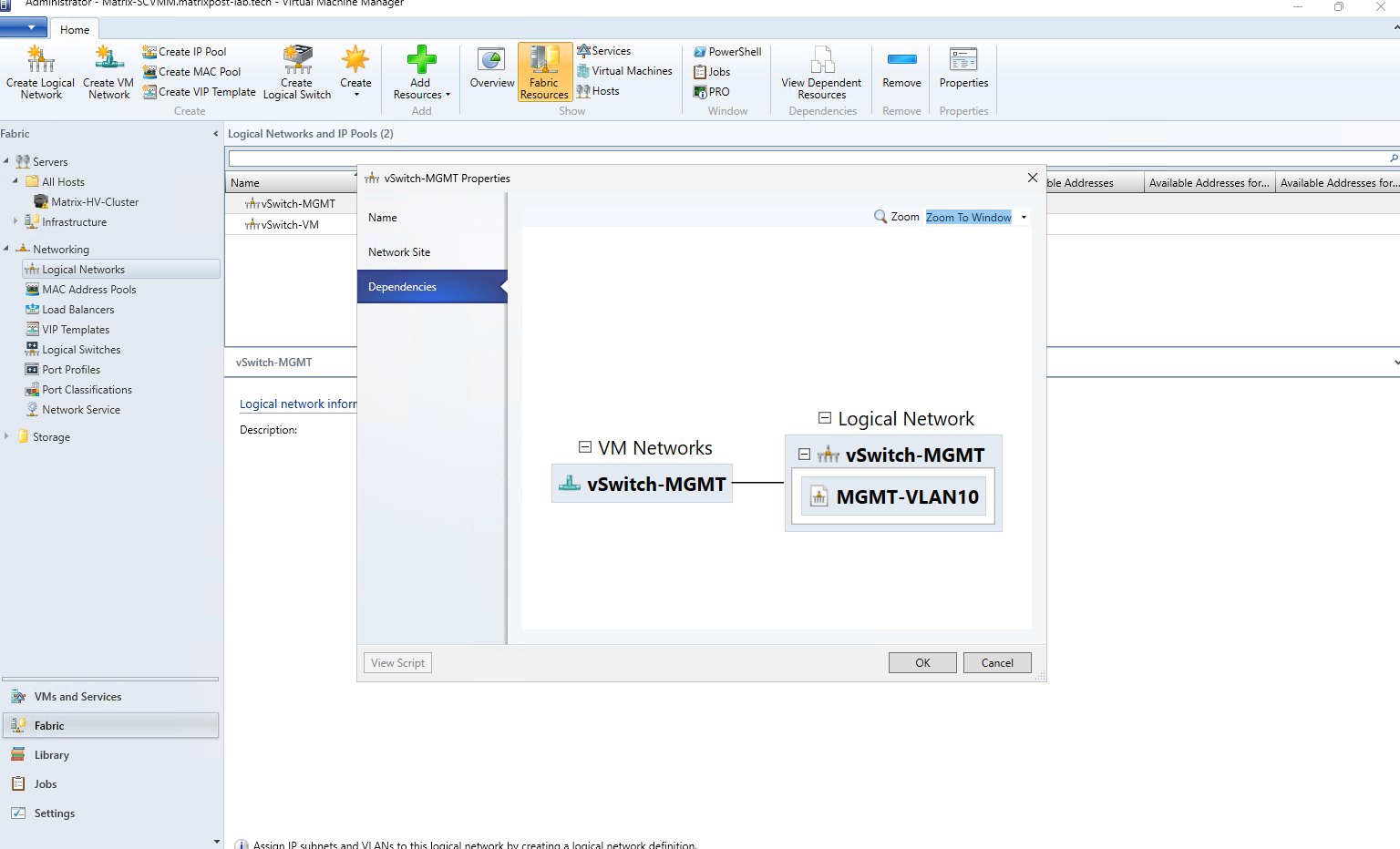
Under Dependencies, SCVMM now shows how the discovered vSwitch-MGMT VM Network is associated with the vSwitch-MGMT Logical Network, which in turn contains our MGMT-VLAN10 Network Site. This provides a useful overview of how the existing Hyper-V network is represented by SCVMM’s logical networking model.
As already mentioned I was then trying to configure the VM network in exactly the same way and was running into the error shown below.
Since SCVMM does not allow the same IP subnet to be assigned to two separate Logical Networks, we need to separate the VM network from the management network.
In my lab, I will therefore move the VM network to VLAN 20 with a separate subnet and add a router VM to provide routing between VLAN 10 and VLAN 20; VLAN 20 is already configured on the physical switches and trunk ports.
To avoid changing the existing infrastructure VMs, I will keep them on the management network and use the dedicated vSwitch-VM only for new workload VMs. These VMs will use the separate 10.0.20.0/24 subnet and VLAN 20, providing a cleaner and more production-like separation between management and workload traffic.
For the existing VMs moved to
vSwitch-MGMT, I also had to remove the VLAN 10 tag from their virtual network adapters, because the physical adapters of the management SET are connected to access ports already configured for VLAN 10. Therefore, traffic onvSwitch-MGMTmust leave Hyper-V untagged, with the physical switches assigning it to VLAN 10.
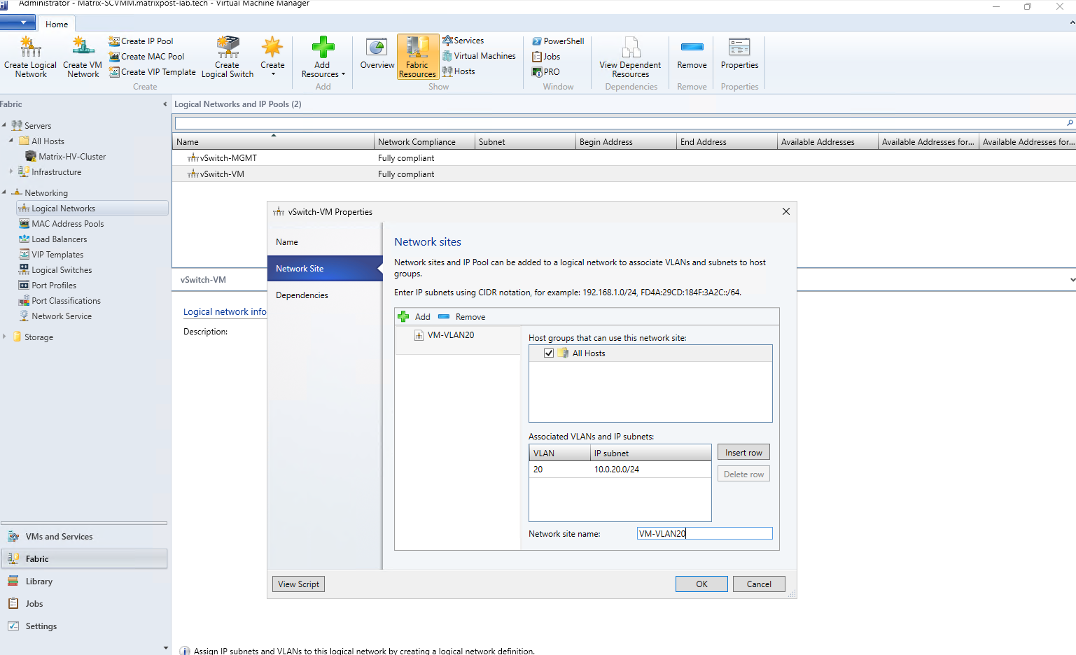
For the vSwitch-VM logical network, we now create a dedicated network site named VM-VLAN20 and associate it with VLAN 20 and the 10.0.20.0/24 subnet.
This network will be used for newly deployed workload VMs, while SCVMM can consistently map the logical network configuration to both Hyper-V cluster hosts.
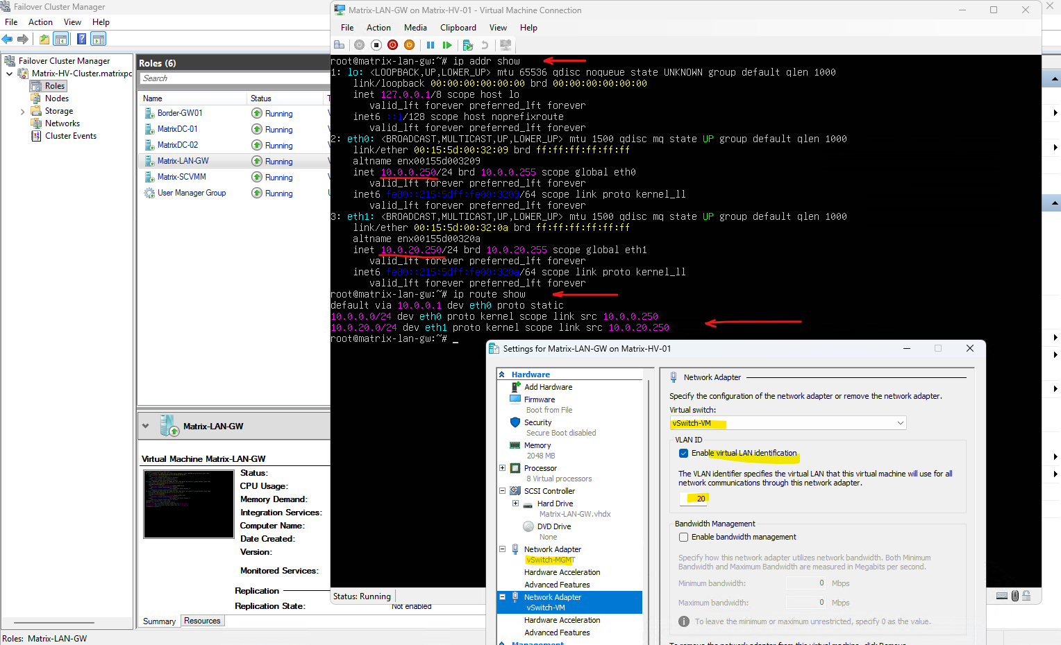
To provide routing between both networks, I deployed a small Ubuntu Server VM (
Matrix-LAN-GW) with one interface connected untagged to the10.0.0.0/24network, since the physical adapters ofvSwitch-MGMTare connected to access ports configured for VLAN 10, and a second interface connected tovSwitch-VMusing VLAN 20 (10.0.20.250/24). With IPv4 forwarding enabled, the VM routes traffic between the10.0.0.0/24and10.0.20.0/24networks.
After defining the network sites, VLANs, and IP subnets for our logical networks, we can optionally create an IP Pool in SCVMM. The IP Pool allows SCVMM to centrally manage and automatically assign IP addresses and related network settings to newly deployed virtual machines.
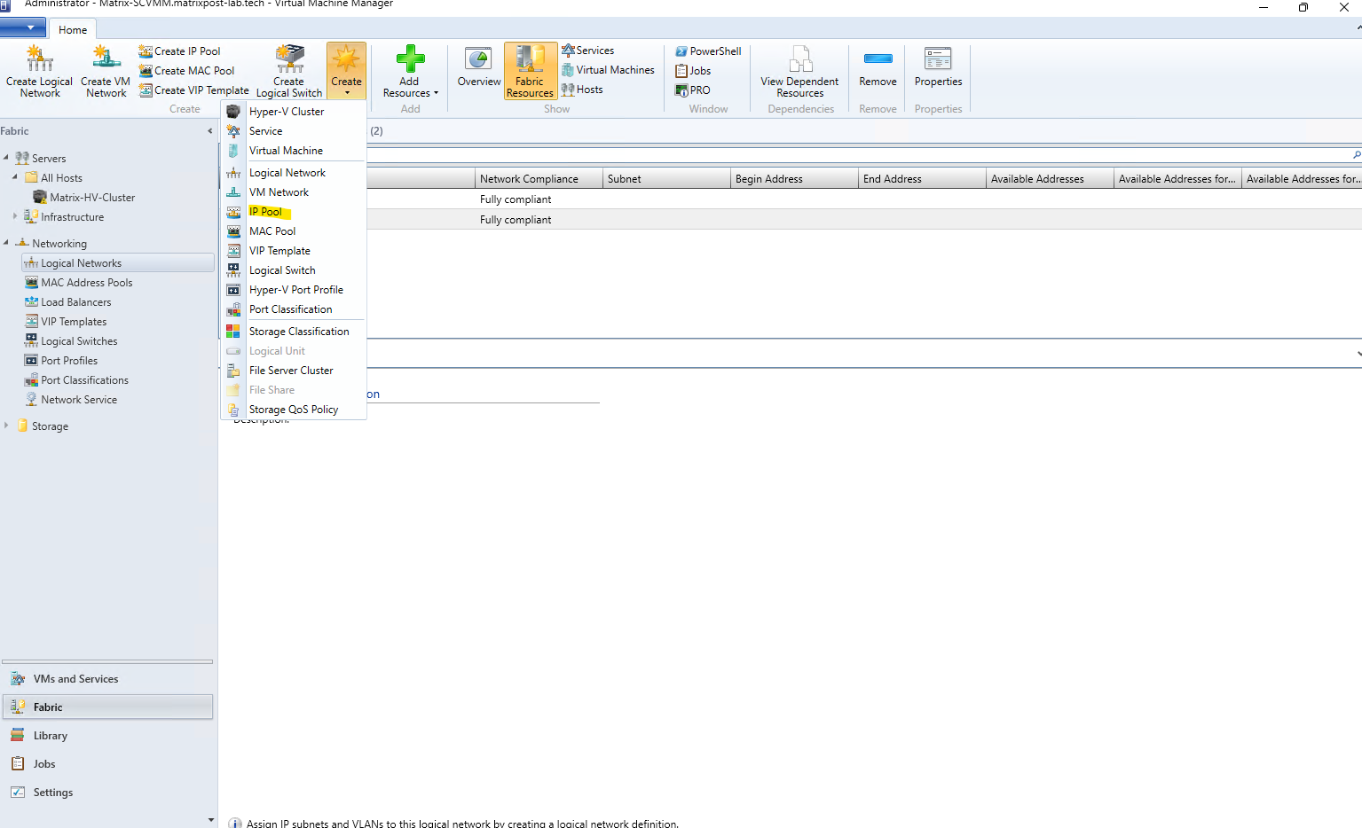
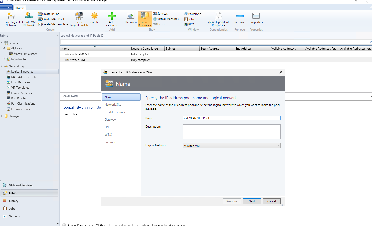
First, we provide a descriptive name for the new IP Pool and associate it with the corresponding logical network. In our case, we create VM-VLAN20-IPPool and assign it to the vSwitch-VM logical network.
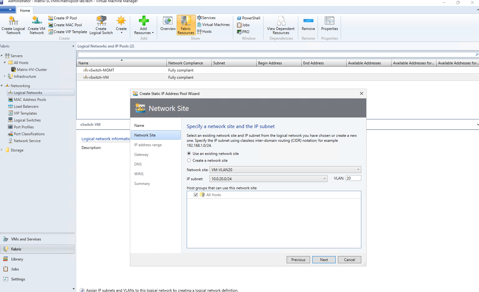
Next, we select the previously created VM-VLAN20 network site, which automatically associates the IP Pool with VLAN 20 and the 10.0.20.0/24 subnet. The network site is available to our All Hosts host group.
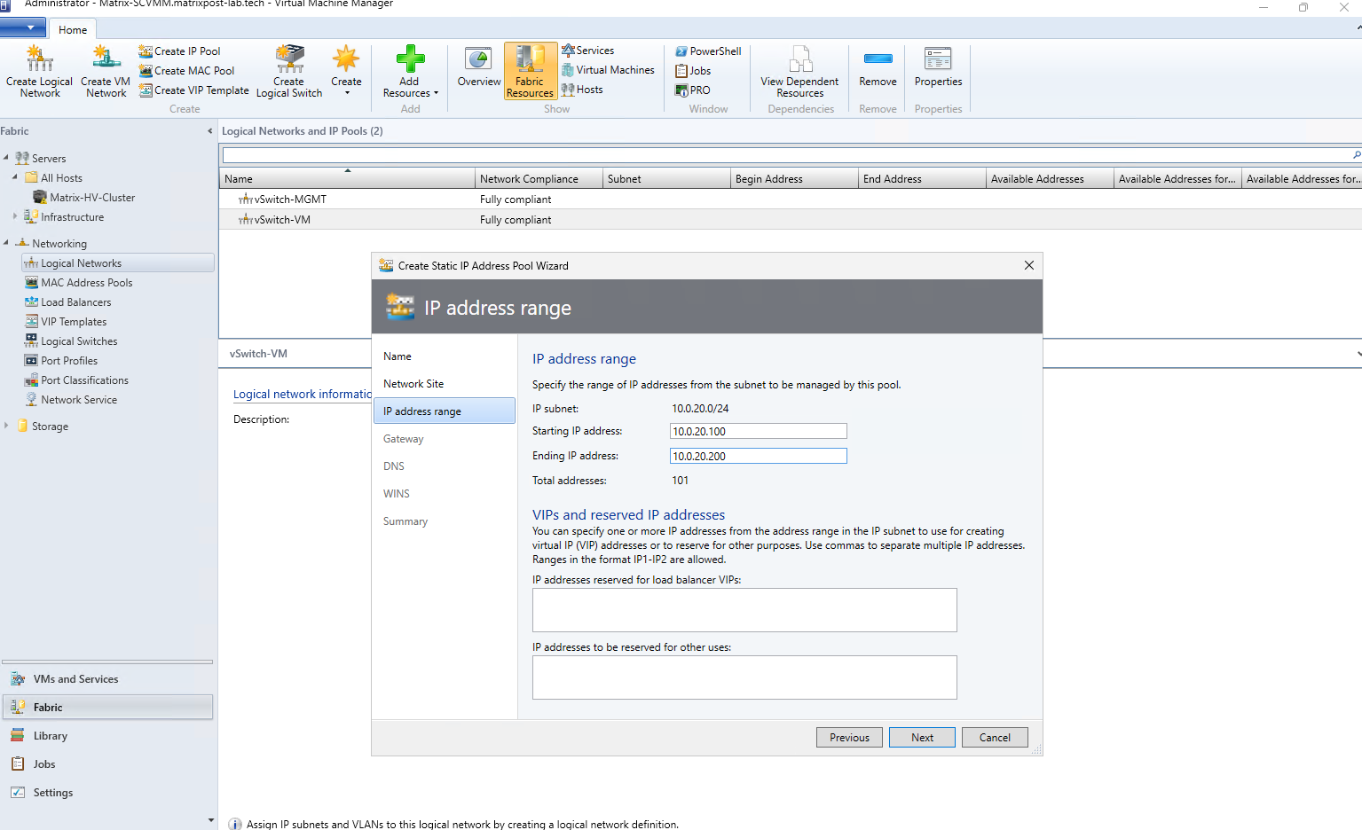
Here we define the range of IP addresses that SCVMM can automatically allocate from the 10.0.20.0/24 subnet. In our lab, we reserve 10.0.20.100 through 10.0.20.200 for SCVMM-managed VM deployments, leaving the remaining addresses available for manually assigned infrastructure systems.
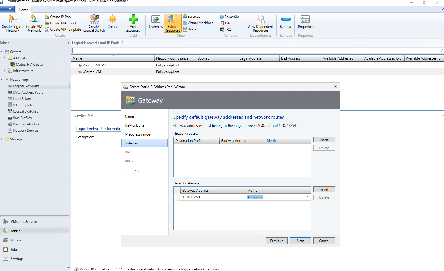
Here we specify the default gateway that SCVMM will assign to VMs using this IP Pool. In our case, this is 10.0.20.250, the Matrix-LAN-GW Ubuntu router that provides connectivity from VLAN 20 / 10.0.20.0/24 to the rest of our lab network.
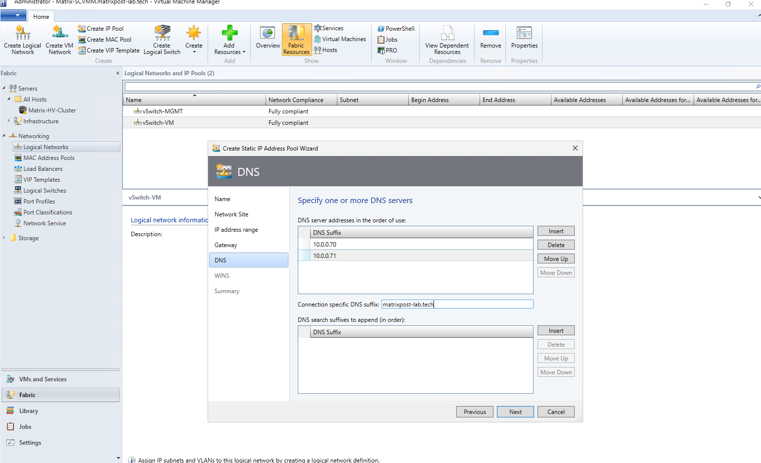
Next, we configure the DNS settings for the IP pool by specifying our two domain controllers (10.0.0.70 and 10.0.0.71) as DNS servers. We also configure matrixpost-lab.tech as the connection-specific DNS suffix for virtual machines using this network.
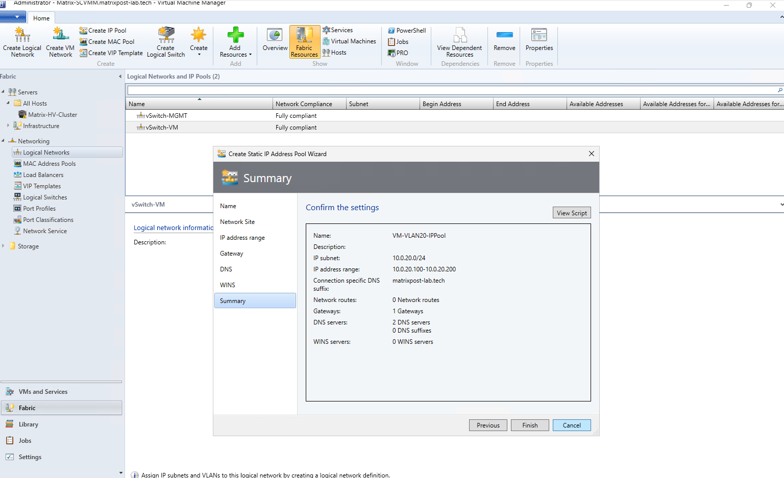
Finally, review the IP pool configuration in the Summary before completing the wizard. SCVMM will manage addresses 10.0.20.100–10.0.20.200 from the 10.0.20.0/24 subnet and apply the previously configured gateway, DNS servers, and DNS suffix.
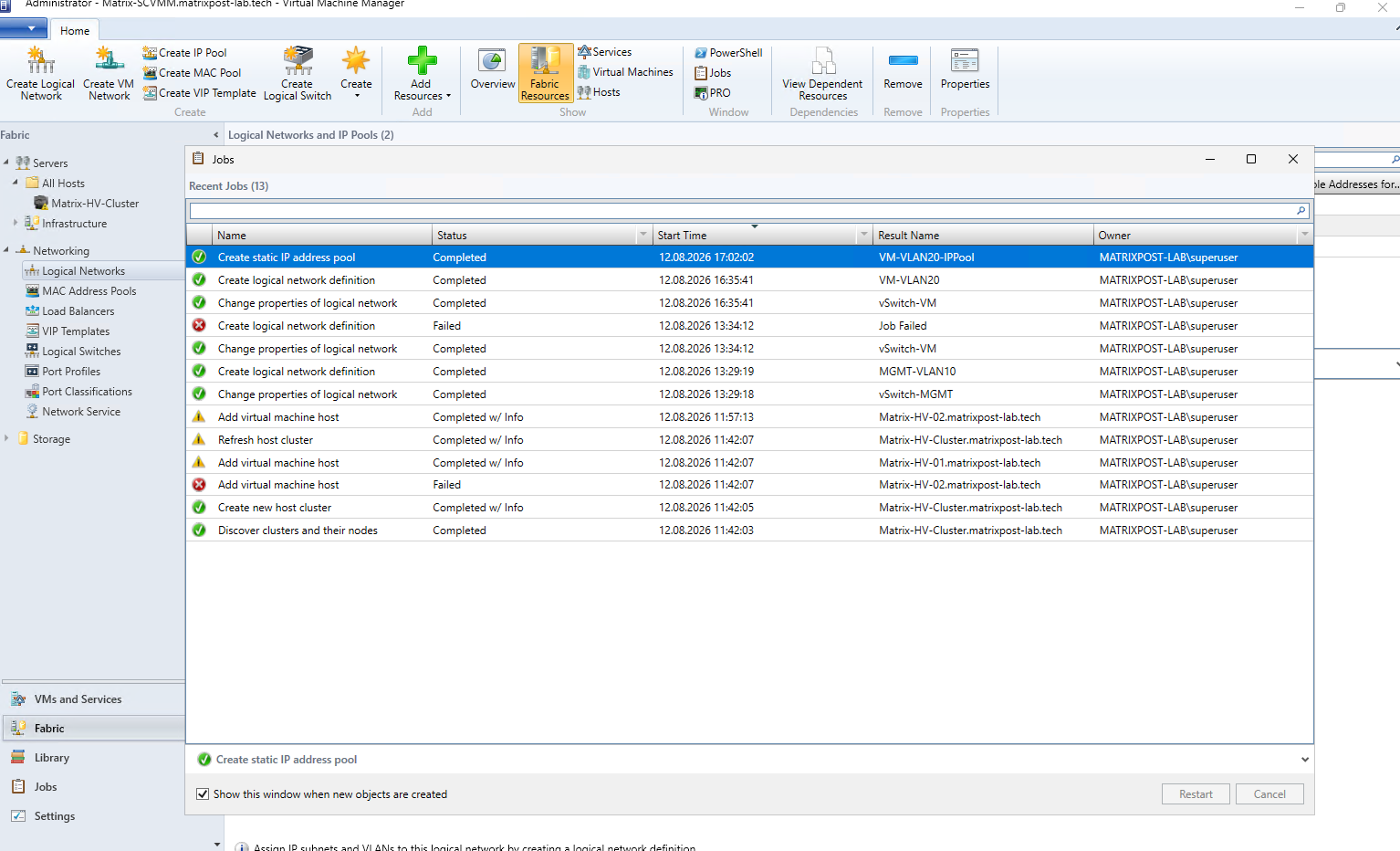
The IP pool is then created by SCVMM, and the corresponding job should complete successfully. We can verify this in the Jobs window, where the new VM-VLAN20-IPPool is shown with the status Completed.
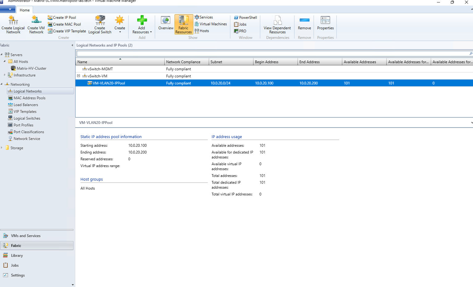
The newly created IP pool is now displayed below the vSwitch-VM logical network and shows a Fully compliant state. SCVMM can now manage and allocate the 101 configured addresses from 10.0.20.100 through 10.0.20.200 for workloads connected to this network.
One interesting difference compared to VMware vSphere is that SCVMM provides integrated IP address pools (IPAM) for centrally managing and allocating IP addresses to virtual machines.
We will cover this and the other key differences between SCVMM and vSphere in a dedicated section later in this article.
Configuring Logical Switches in System Center Virtual Machine Manager
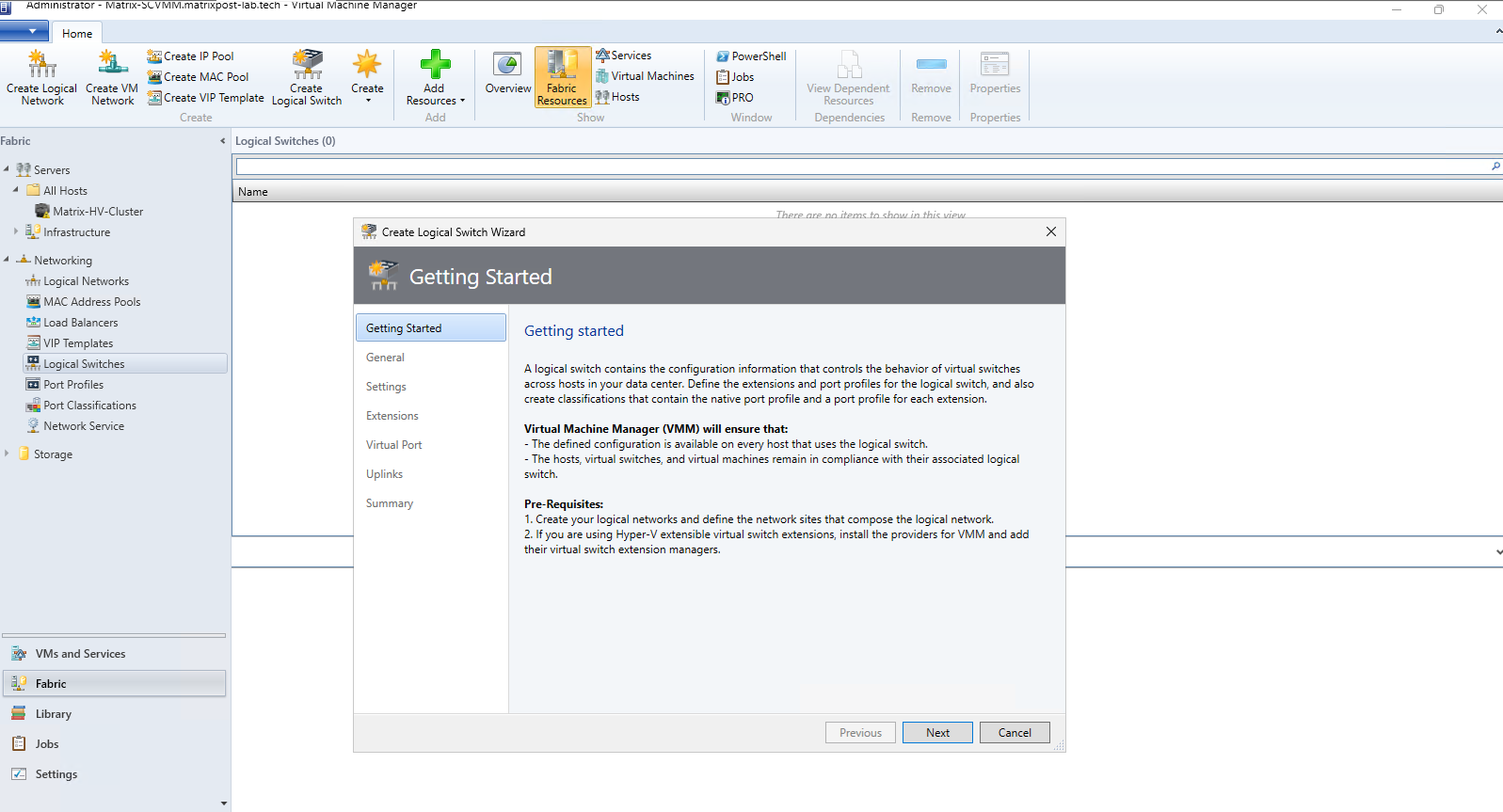
After defining the logical networks, network sites, VLANs, and IP address pools, we can move on to Logical Switches. In SCVMM, a Logical Switch provides a centralized and consistent way to define how networking should be configured across our Hyper-V hosts, including uplinks, port profiles, and network connectivity.
In SCVMM, navigate to Fabric → Networking → Logical Switches. Since no Logical Switches exist yet in our environment, we start by creating a new one that will later be associated with the physical network adapters and networking configuration of our Hyper-V hosts.
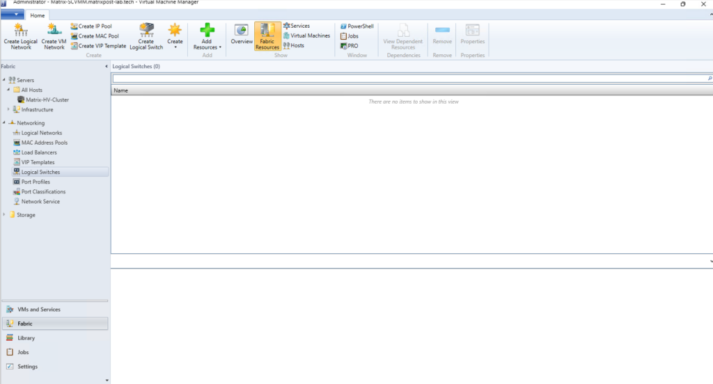
To create the Logical Switch, we can either select Create → Logical Switch or simply click Create Logical Switch directly in the ribbon bar. This opens the wizard where we can define the standardized switch configuration that will later be applied to our Hyper-V hosts.
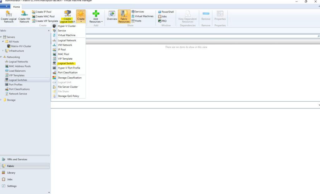
SCVMM uses this configuration to ensure that the same virtual switch settings are available and remain consistent across all Hyper-V hosts associated with the Logical Switch.
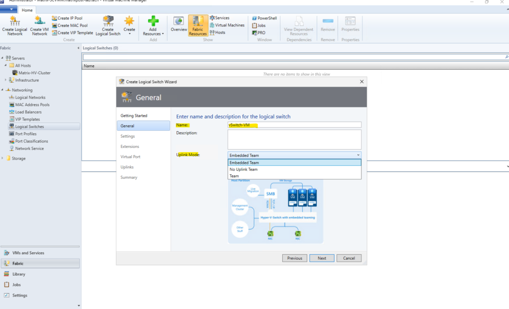
When creating the Logical Switch, make sure to use the same name as the existing virtual switch on the Hyper-V hosts. In our case, we therefore name the Logical Switch vSwitch-VM and select Embedded Team as the uplink mode to match our existing SET-based configuration.
Embedded Team – Uses Switch Embedded Teaming (SET), integrated directly into the Hyper-V Virtual Switch. This is the recommended option for Windows Server 2016 and later and is what we use here.
No Uplink Team – Uses only a single physical network adapter, providing no NIC teaming or uplink redundancy.
Team – Uses the older LBFO (Load Balancing/Failover) NIC Teaming technology. This is the legacy approach and has largely been superseded by SET for Hyper-V networking.
The minimum bandwidth mode must also match the configuration of the existing vSwitch-VM on the Hyper-V hosts. Since SCVMM detects our existing switch as using Absolute, we select Absolute here as well; otherwise, SCVMM will not allow the existing virtual switch to be converted to the Logical Switch.
We leave SR-IOV (Single Root I/O Virtualization) disabled in our configuration. SR-IOV allows supported virtual machines to access the physical network adapter more directly, bypassing parts of the Hyper-V virtual switching path to reduce latency and CPU overhead, but it requires compatible hardware and must be enabled when the Logical Switch is initially created.
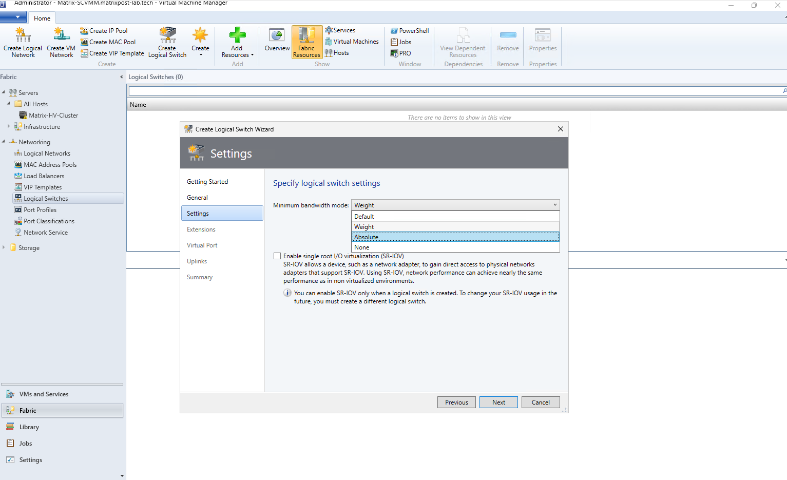
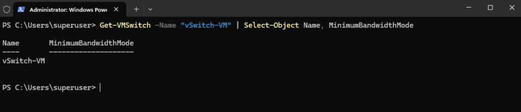
We can check the MinimumBandwidthMode reported by Hyper-V for the existing virtual switch by running the following PowerShell command:
Interestingly, MinimumBandwidthMode is empty because we did not explicitly specify
-MinimumBandwidthModewhen we originally createdvSwitch-VM. However, when SCVMM discovers the existing switch, it interprets this configuration as Absolute, so we must use Absolute for the Logical Switch as well to make both configurations compatible for conversion.
Get-VMSwitch -Name "vSwitch-VM" | Select-Object Name, MinimumBandwidthMode
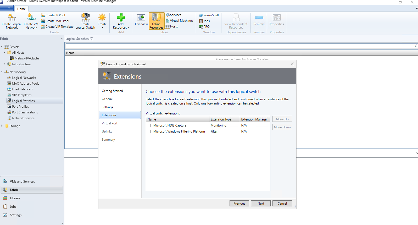
Here we can optionally enable Hyper-V Virtual Switch Extensions, which allow additional monitoring or filtering functionality to be inserted into the virtual switch data path. For our configuration, no extensions are required, so we leave both Microsoft NDIS Capture and Microsoft Windows Filtering Platform disabled and continue with the default settings.
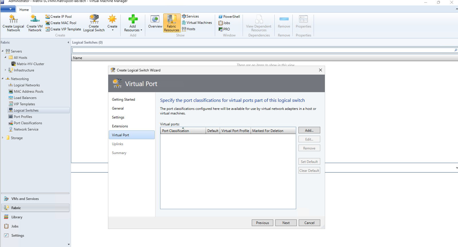
Here we can define Virtual Port Profiles and Port Classifications, which control settings such as bandwidth, security, and offload capabilities for VM network adapters. For our simple VM network, we do not need any special port configuration yet, so we can leave this section empty and continue.
Compared with VMware vSphere, SCVMM separates Port Classifications from the underlying Virtual Port Profiles that contain the actual network settings. In vSphere, comparable settings such as security, traffic shaping, and NIC teaming are generally configured directly on the Standard or Distributed Port Group.
We’ll cover this architectural difference in more detail later when comparing SCVMM and vSphere networking side by side.
This is the important Uplinks step. Here we define the uplink port profile that determines how the physical network adapters of the Hyper-V hosts connect to the Logical Switch and which logical networks are available through those uplinks.
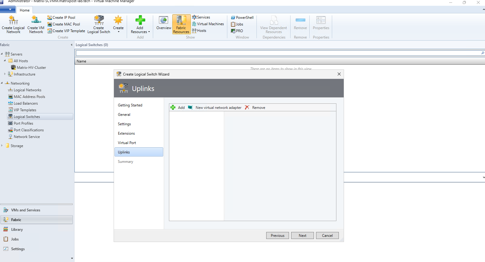
Click Add first, this is where we’ll create/configure the uplink profile for our vSwitch-VM/VLAN 20 network.
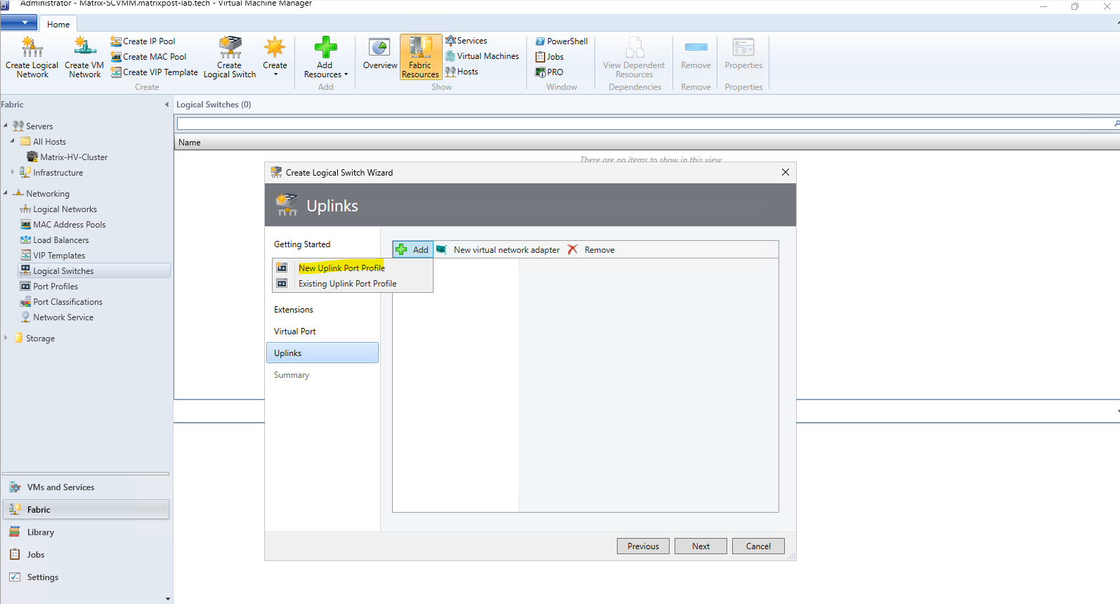
Since this is our first Logical Switch and no suitable profile exists yet, we select New Uplink Port Profile.
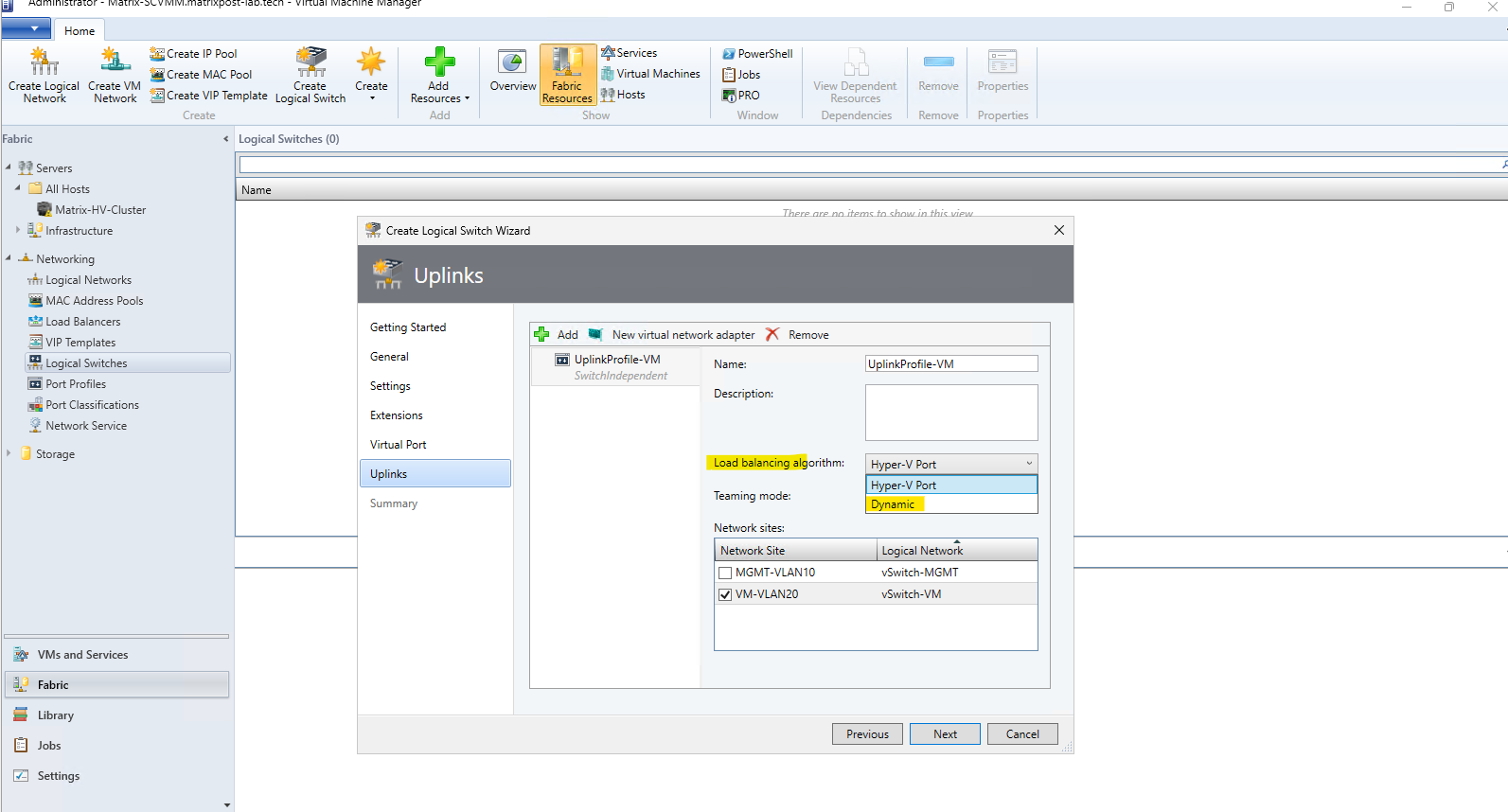
Here we configure the Uplink Port Profile used by the Logical Switch.
For our SET configuration, we keep Switch Independent teaming and select Dynamic as the load-balancing algorithm, which dynamically distributes outbound traffic across the available physical adapters and generally provides better bandwidth utilization than Hyper-V Port, where each virtual NIC is primarily mapped to a single team member. We associate the profile only with the VM-VLAN20 network site, since this Logical Switch is dedicated to the VM network.
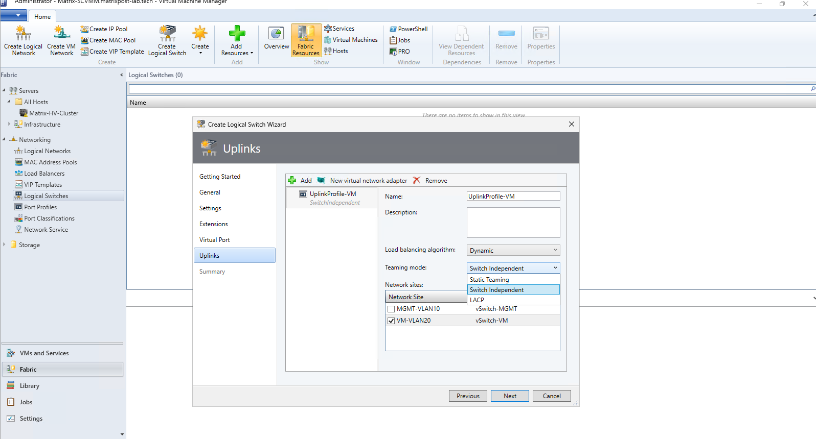
For the Teaming mode, SCVMM provides three options:
Switch Independent – The physical switches do not need to know about the team, allowing the NICs to connect to different physical switches. This is the recommended and required mode for SET and provides straightforward redundancy.
Static Teaming – The switch ports are manually configured as a static aggregation group on the physical switch. Both the host and switch must therefore be configured consistently.
LACP – Uses the Link Aggregation Control Protocol (802.1AX/802.3ad) to dynamically negotiate the aggregated links with a compatible physical switch.
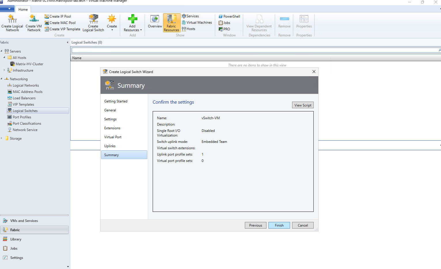
Finally, review the Logical Switch configuration on the Summary page. We can see that LogicalSwitch-VM uses Switch Embedded Teaming (SET) with one Uplink Port Profile; click Finish to create the Logical Switch in SCVMM.
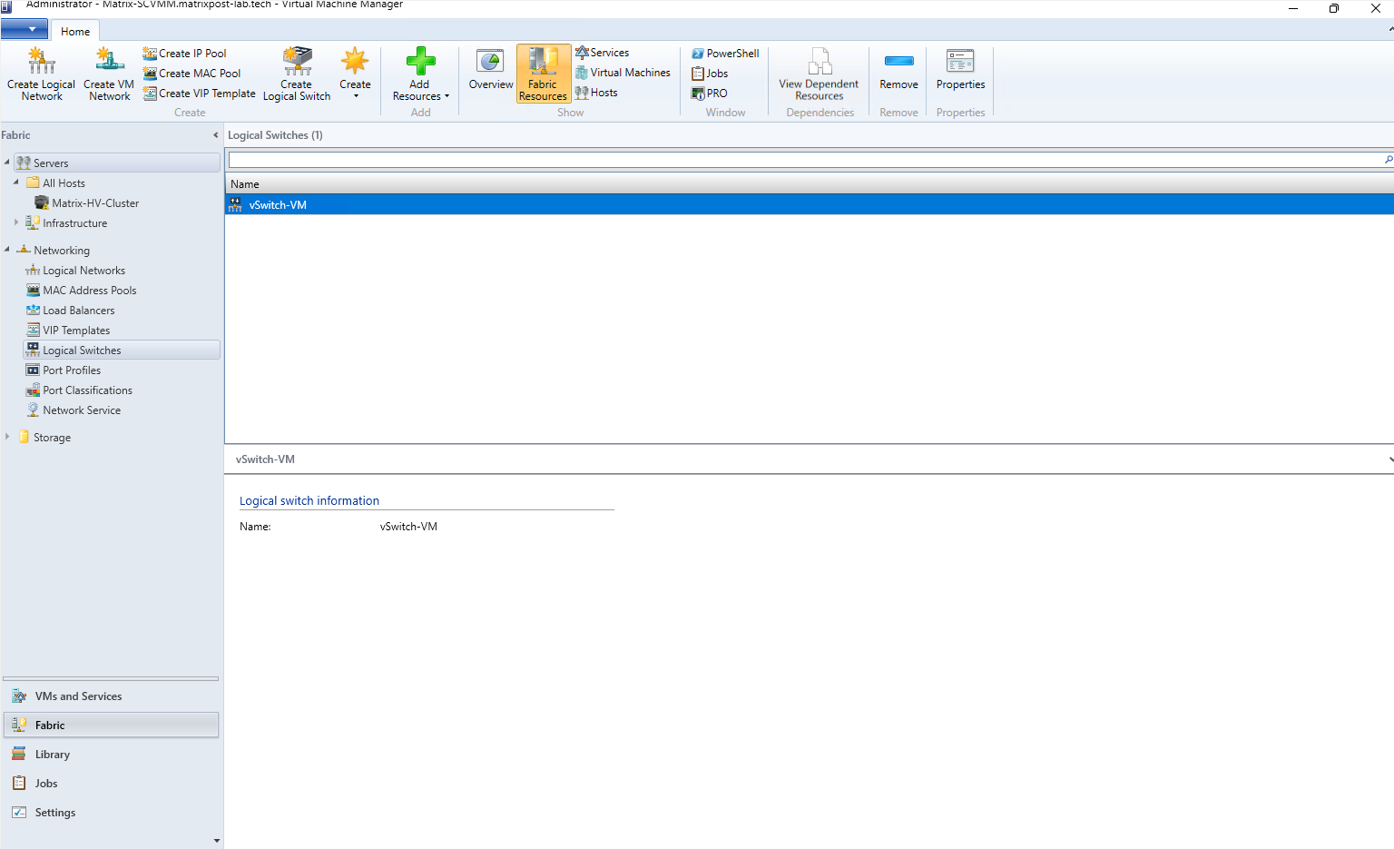
The Logical Switch vSwitch-VM is now created and centrally available in SCVMM. At this point it represents the desired network configuration; in the next step, we can apply the Logical Switch to the physical VM network adapters of our Hyper-V hosts.
Applying the Logical Switch to the Hyper-V Hosts
We have only created the Logical Switch definition in SCVMM so far; this does not modify the networking on the Hyper-V hosts yet.
Next, we assign LogicalSwitch-VM to the physical adapters used for VM traffic, allowing SCVMM to centrally deploy and manage the corresponding SET-based Hyper-V virtual switch on each host.
An SCVMM Logical Switch plays a similar role to a vSphere Distributed Switch (VDS): both provide a centrally defined networking configuration that can be applied consistently across multiple virtualization hosts.
The mapping is roughly:
| SCVMM / Hyper-V | VMware vSphere |
|---|---|
| Logical Switch | vSphere Distributed Switch (VDS) |
| Uplink Port Profile | VDS uplink / teaming policies |
| Logical Network / Network Site | Network/VLAN definition |
| Port Classification + Virtual Port Profile | Distributed Port Group + policies |
| Physical NICs assigned to Logical Switch | Physical NICs (vmnics) assigned to VDS uplinks |
| SCVMM centralized management | vCenter centralized management |
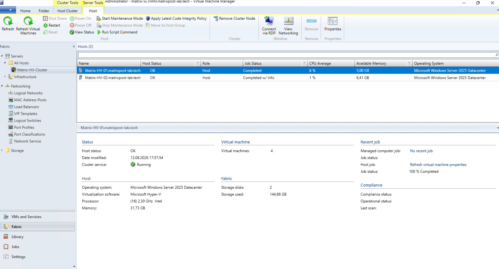
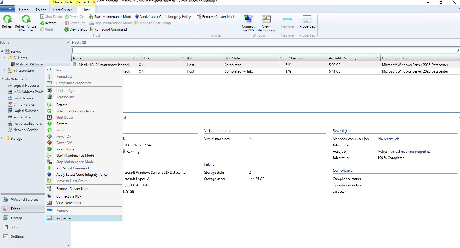
Next, go to Fabric → Servers → All Hosts → Matrix-HV-Cluster, open the Properties of the first Hyper-V host, and select Virtual Switches.
Here we can see the existing, locally configured vSwitch-VM on the Hyper-V host.
Note: As already mentioned, SCVMM recognizes our existing vSwitch-VM as using the
Absoluteminimum bandwidth mode. Since we created the Logical Switch to use the same bandwidth mode and matches the existing switch configuration, the Convert to Logical Switch option becomes available.
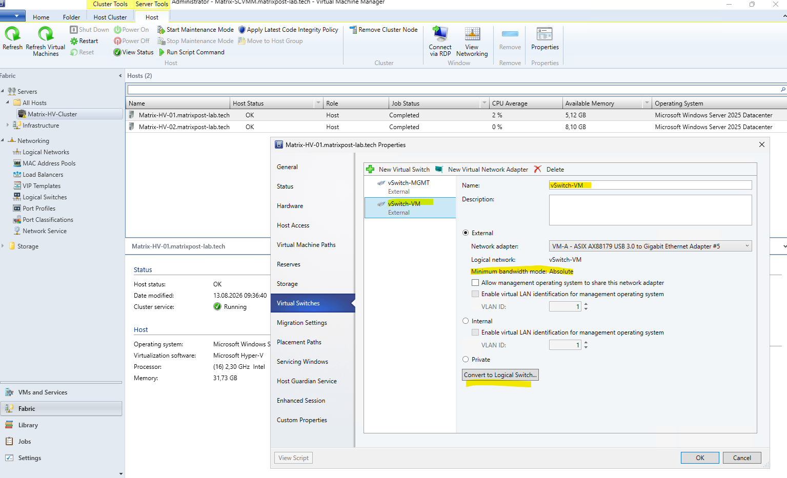
When we originally created the SET-based vSwitch-VM in Part 2 – Configuring Hyper-V Networking, SET, and Failover Clustering, we did not explicitly configure a minimum bandwidth mode. SCVMM nevertheless recognizes the existing switch as using Absolute, as we saw above. Interestingly, querying the switch directly with PowerShell returns an empty MinimumBandwidthMode property.
Get-VMSwitch -Name "vSwitch-VM" | Select-Object Name, MinimumBandwidthMode
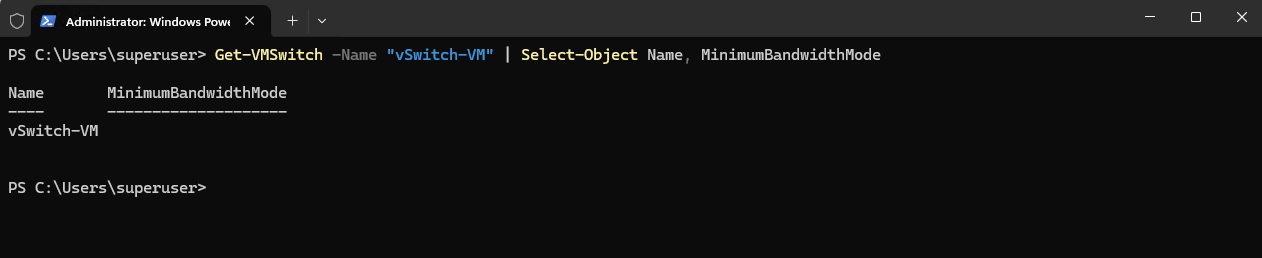
Although PowerShell does not display an explicitly configured value here, SCVMM evaluates the existing vSwitch-VM as Absolute. Therefore, the SCVMM Logical Switch must also use Absolute for the existing virtual switch to be eligible for conversion.
Next, click Convert to Logical Switch… for vSwitch-VM. This starts the conversion of the existing host-level Hyper-V virtual switch into an SCVMM-managed instance of our vSwitch-VM Logical Switch, while retaining the existing network connectivity.
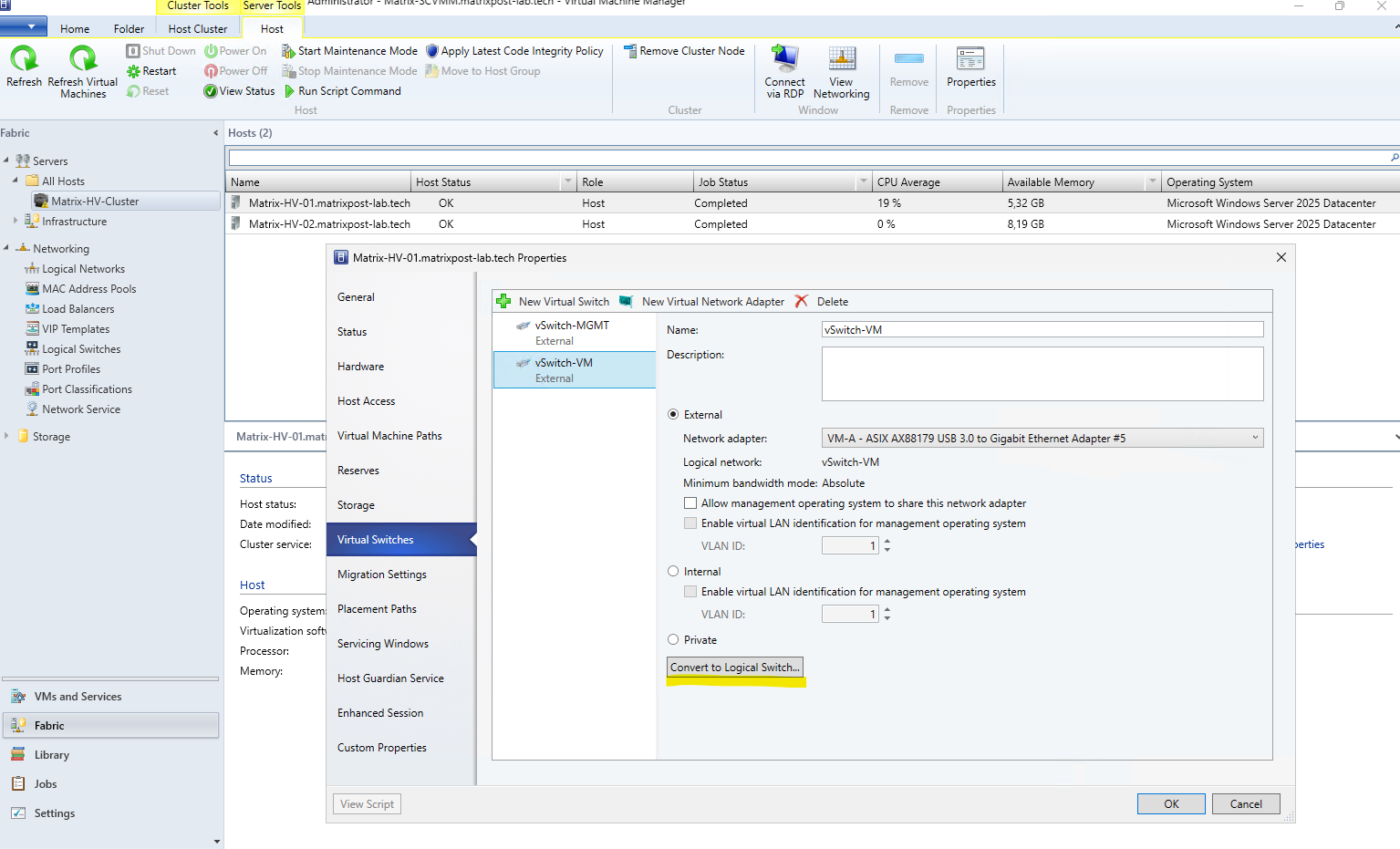
Here SCVMM automatically selects the matching vSwitch-VM Logical Switch and our UplinkProfile-VM. The wizard also confirms that the minimum bandwidth mode, teaming mode, and available network sites must match the existing standard vSwitch before conversion; click Convert to apply the centrally managed Logical Switch configuration to the host.
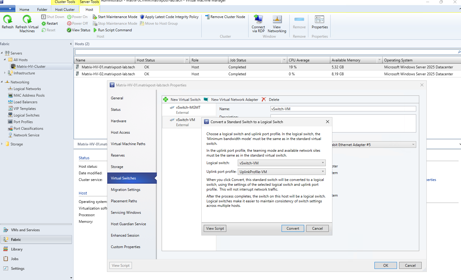
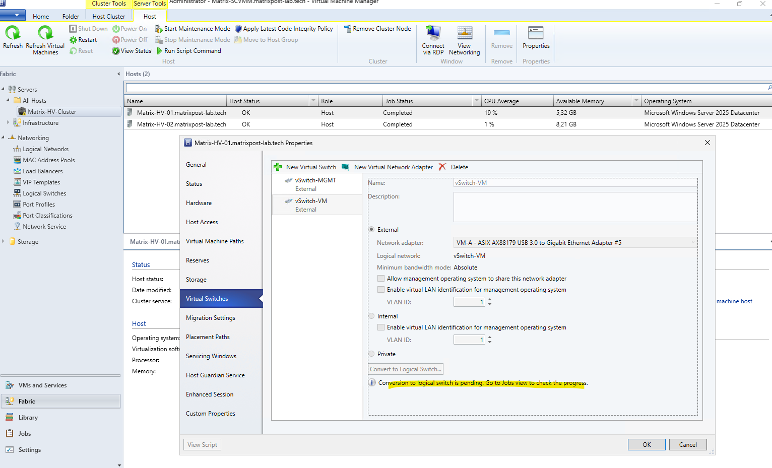
After clicking Convert, SCVMM starts the conversion as a background job. The host properties indicate that the conversion to the Logical Switch is pending; we can switch to the Jobs workspace to monitor the conversion and verify that it completes successfully.
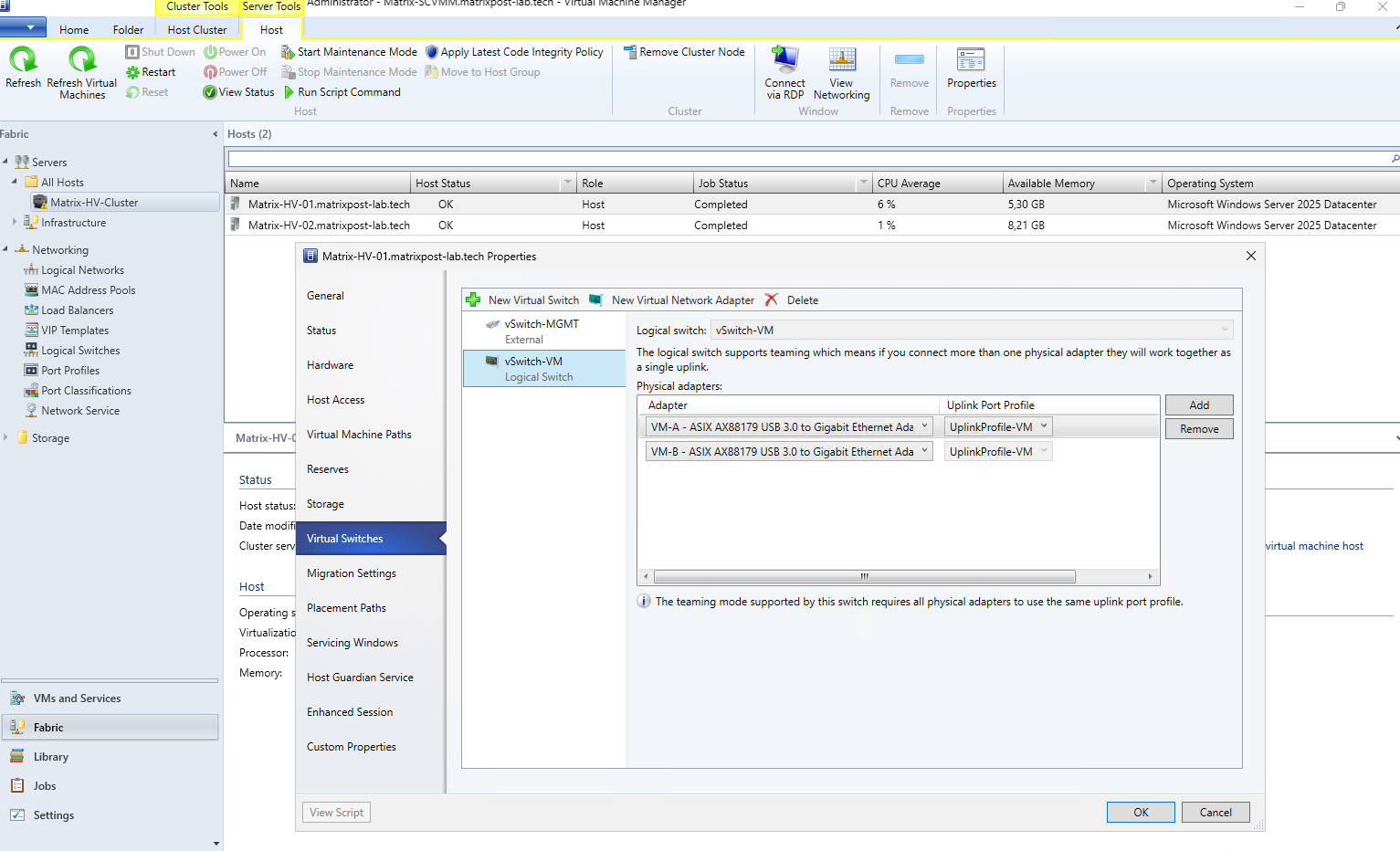
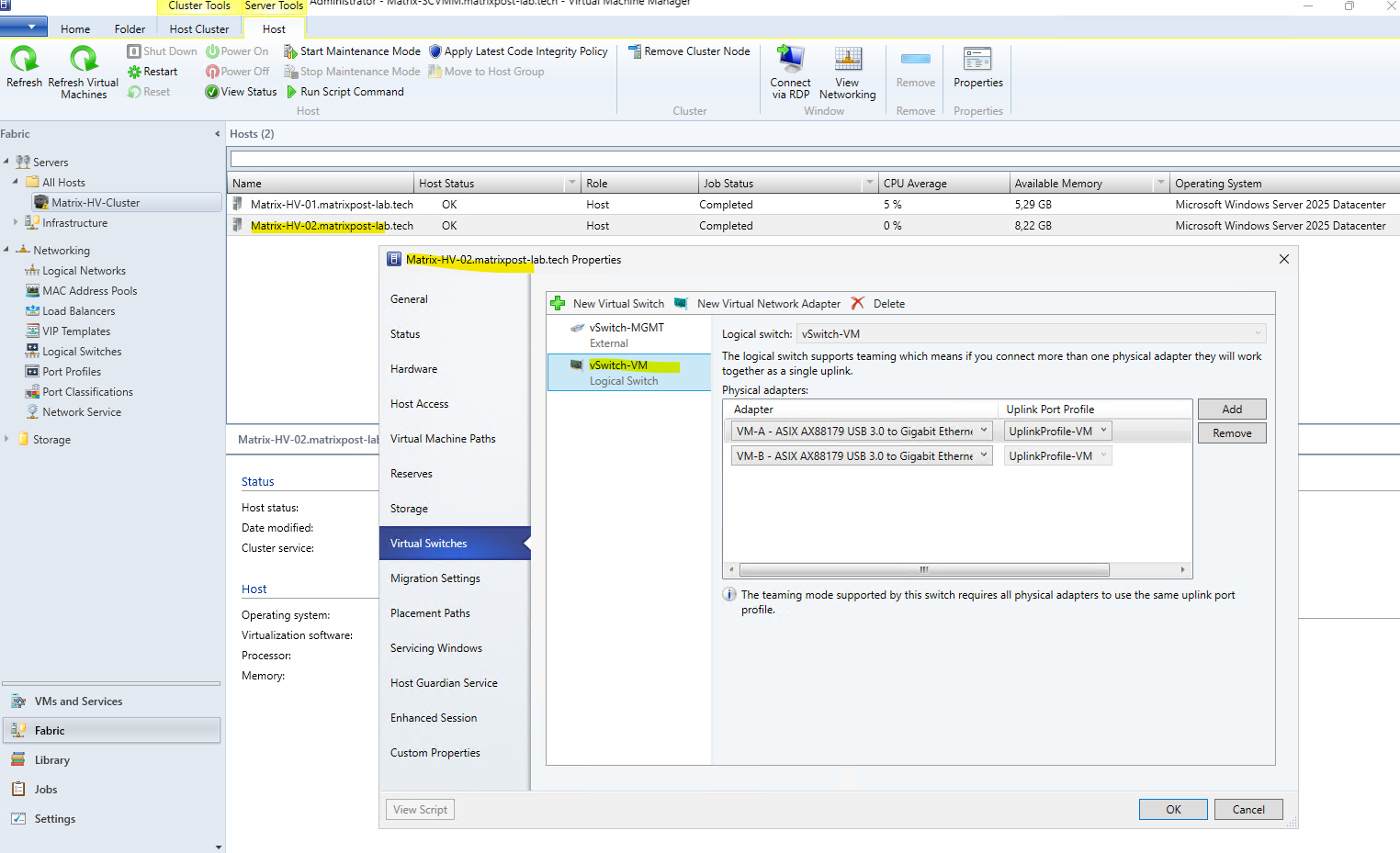
After the conversion has completed, vSwitch-VM is now shown as a Logical Switch on the Hyper-V host.
We can also see that both physical adapters
VM-AandVM-Bare assigned to the centrally defined UplinkProfile-VM, preserving our original two-adapter SET configuration under SCVMM management.
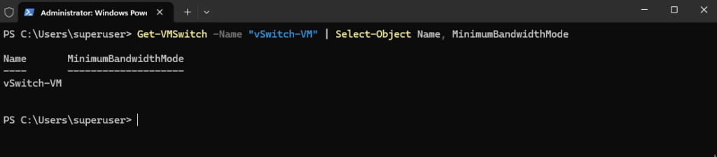
Interestingly, even after converting vSwitch-VM to an SCVMM Logical Switch, the MinimumBandwidthMode property returned by Get-VMSwitch remains empty.
SCVMM nevertheless represents the switch as using Absolute, so the value shown in SCVMM should be treated as SCVMM’s interpretation of the switch configuration rather than an explicitly reported Hyper-V PowerShell property.
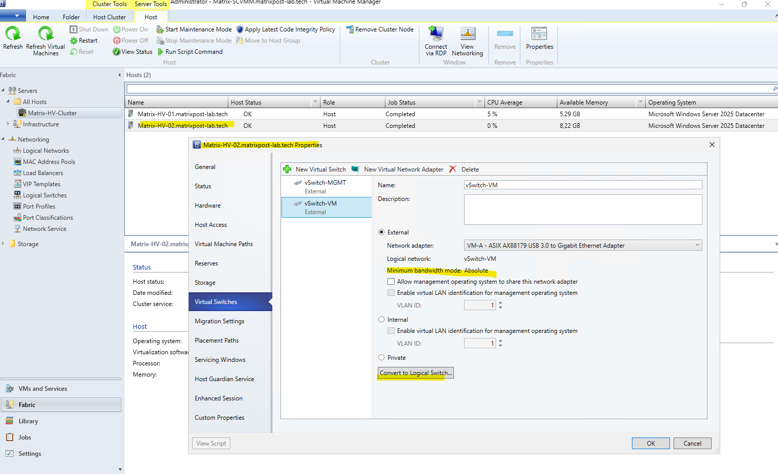
We now repeat the same conversion on the second Hyper-V host, Matrix-HV-02.
SCVMM again recognizes the existing vSwitch-VM as using Absolute, and since its configuration matches our centrally defined
vSwitch-VMLogical Switch and UplinkProfile-VM, the Convert to Logical Switch… option is available.
After repeating the conversion on the second Hyper-V host, Matrix-HV-02, both cluster nodes now use the centrally managed vSwitch-VM Logical Switch. Both physical VM network adapters (VM-A and VM-B) are attached to the same UplinkProfile-VM, providing a consistent SET-based network configuration across the Hyper-V cluster.
Verifying the Automatically Created VM Network
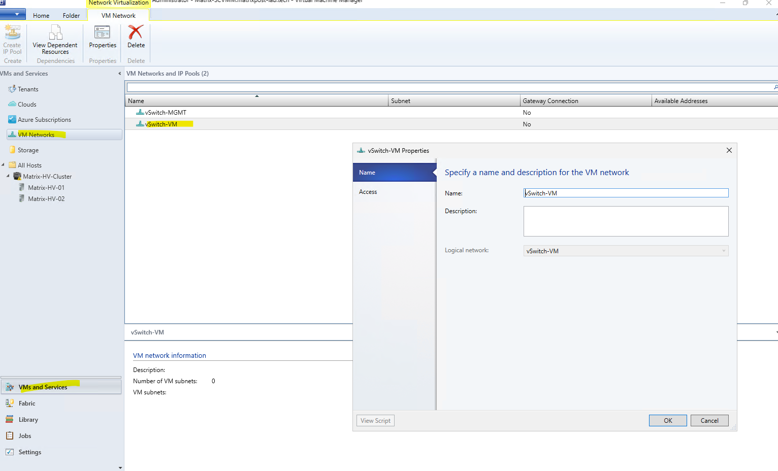
Because our vSwitch-VM Logical Network is configured as a simple connected network without Hyper-V Network Virtualization, SCVMM automatically creates a corresponding VM Network with the same name. Therefore, we do not need to create a VM Network manually.
We can verify this under VMs and Services → VM Networks. As shown below, the vSwitch-VM VM Network already exists and is associated with our vSwitch-VM Logical Network, ready to provide network connectivity to our virtual machines.
Note: From a VMware vSphere perspective, SCVMM VM Networks together with their VM Subnets correspond roughly to Distributed Port Groups on a vSphere Distributed Switch (VDS). They define the logical network connectivity that virtual machines consume on top of the centrally managed switch infrastructure.
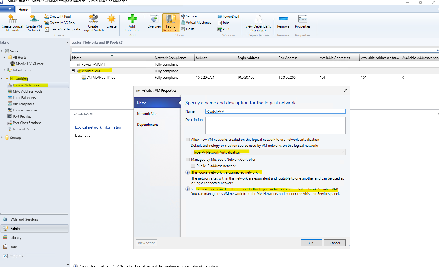
As shown here, the vSwitch-VM Logical Network is configured as a simple connected network, because Allow new VM networks created on this logical network to use network virtualization is not enabled.
Therefore, VMs connect directly to the underlying VLAN/subnet rather than using Hyper-V Network Virtualization (HNV) with isolated and potentially overlapping tenant address spaces.
For comparison, if Hyper-V Network Virtualization (HNV) were enabled, we could create multiple isolated VM Networks on top of the same underlying provider/physical network:
                  Logical / Provider Network
                         10.0.20.0/24
                               |
              Hyper-V Network Virtualization
                 /             |             \
                /              |              \
        Customer A         Customer B       Customer C
        VM Network         VM Network       VM Network
        10.0.0.0/24        10.0.0.0/24      192.168.1.0/24
             |                  |                  |
          VM-A1              VM-B1              VM-C1
        10.0.0.10          10.0.0.10          192.168.1.10
Notice the interesting part: Customer A and Customer B can both have a VM with
10.0.0.10without conflicting. HNV keeps those virtual networks isolated from each other.
For our lab, however, we do not need this additional abstraction. Our VM Networks will map directly to the VLANs and IP subnets configured on the physical network, such as VLAN 20 / 10.0.20.0/24.
The VMware counterpart to Hyper-V Network Virtualization (HNV) is VMware NSX network virtualization.
NSX similarly creates isolated logical/overlay networks on top of a shared physical network, decoupling the VM network topology and addressing from the underlying network infrastructure.
The following diagram shows the conceptual mapping between HNV and VMware NSX:
Microsoft / SCVMM                  VMware

Physical / Provider Network       Physical Underlay Network
          │                                  │
          │                                  │
         HNV                                NSX
          │                              GENEVE Overlay
          │                                  │
    ┌─────┴─────┐                      ┌─────┴─────┐
    │           │                      │           │
VM Network A  VM Network B          Segment A   Segment B
10.0.0.0/24   10.0.0.0/24          10.0.0.0/24 10.0.0.0/24
    │           │                      │           │
  Tenant A    Tenant B               Tenant A    Tenant B
Hyperscalers such as Microsoft Azure use the same fundamental concept at massive scale. Azure Virtual Networks (VNets) provide logically isolated, software-defined networks on shared physical infrastructure, allowing customers to independently define their own private address spaces and network topology without having to manage the underlying physical network.
More about here https://learn.microsoft.com/en-us/azure/azure-government/azure-secure-isolation-guidance.
Deploying a Virtual Machine Using the SCVMM Network
With the Logical Network, Network Site, IP Pool, Logical Switch, Uplink Port Profile, and VM Network now configured, we can finally use the complete SCVMM networking stack for our virtual machines.
In the following section, we will deploy a new test VM on the vSwitch-VM VM Network and verify its connectivity through VLAN 20 and the 10.0.20.0/24 subnet, including automatic IP address assignment from our SCVMM IP Pool.
Creating a VM Template for Automated Deployment
Before deploying our test VM, we first create a small VM Template in SCVMM. A VM Template is required when we want SCVMM to perform automatic static IP address assignment from a configured IP Pool during VM deployment; in addition, it provides a reusable and standardized configuration for future virtual machines connected to our vSwitch-VM VM Network.
Before we can create the SCVMM VM Template, we first need a generalized Windows Server 2025 VHDX that can be used as its base image. Therefore, we will create a temporary Windows Server 2025 VM, install and prepare the operating system, and finally generalize it using Sysprep before adding its VHDX to the SCVMM Library.
On one of the Hyper-V hosts, we create a temporary VM, e.g. W2K25-Template. Install Windows Server 2025 normally from ISO. Install Windows Updates and anything we want in the base image. We do not domain-join it.
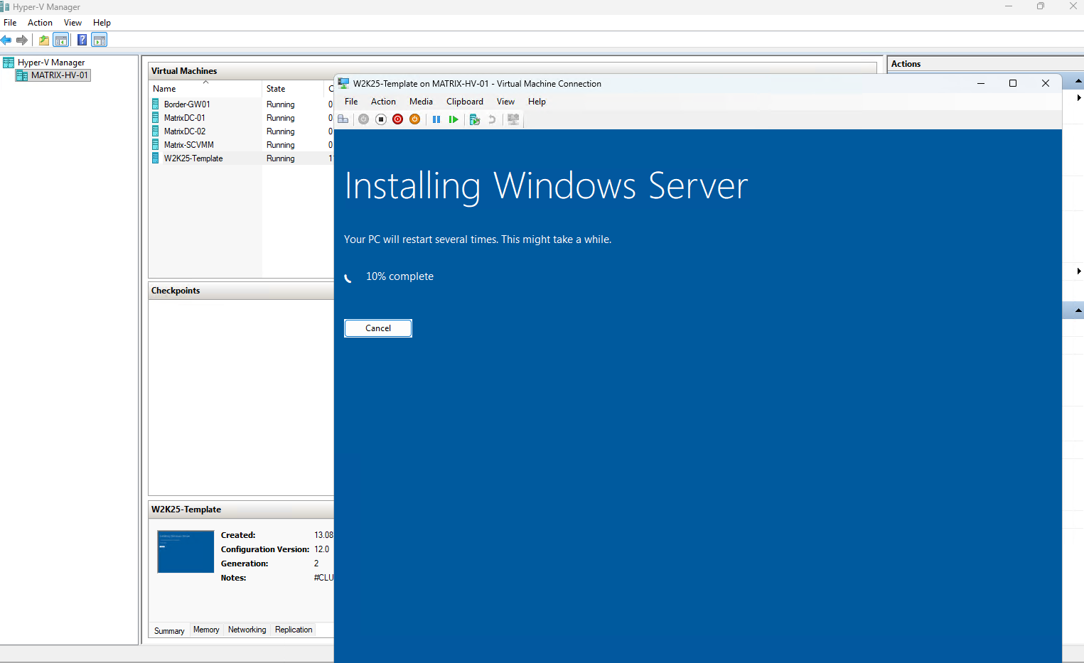
Before using the Windows Server 2025 installation as a reusable template, we need to generalize the operating system using Sysprep.
Sysprep removes machine-specific information such as the system SID and prepares Windows so that each VM deployed from the image can complete its own Out-of-Box Experience (OOBE) and receive a unique identity.
Inside the VM run:
C:\Windows\System32\Sysprep\Sysprep.exe
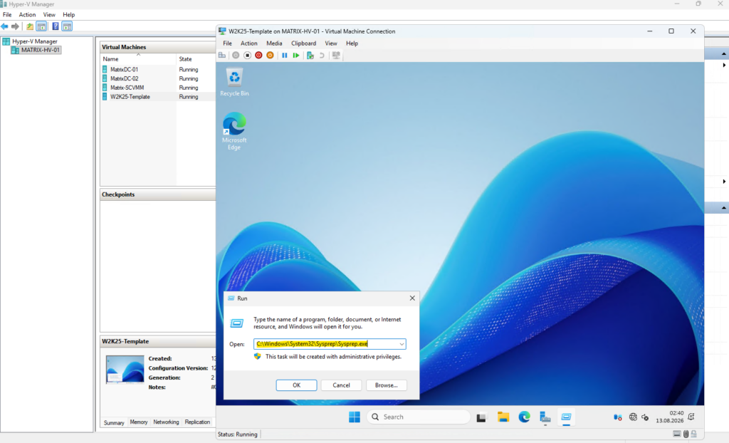
Select Enter System Out-of-Box Experience (OOBE), Generalize and Shutdown.
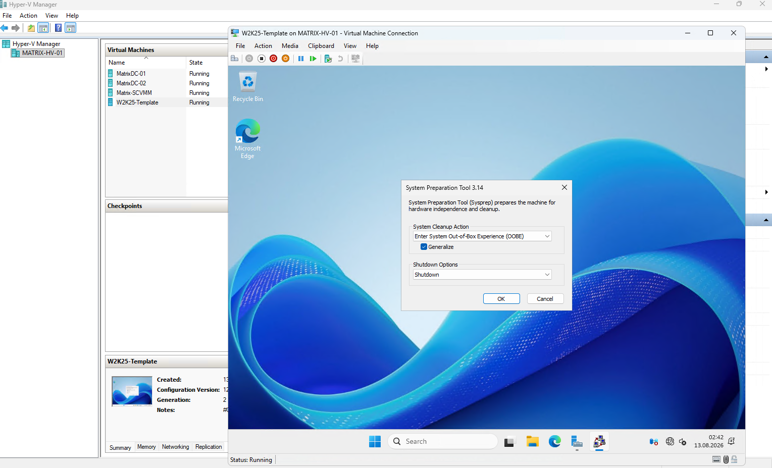
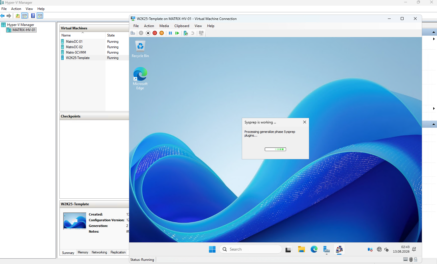
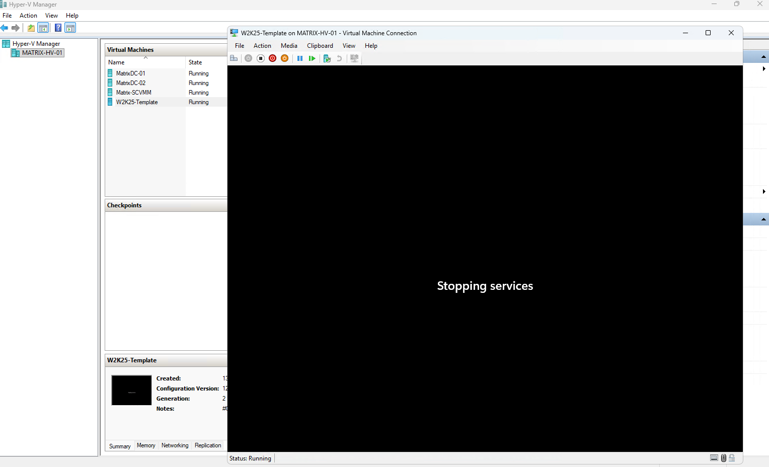
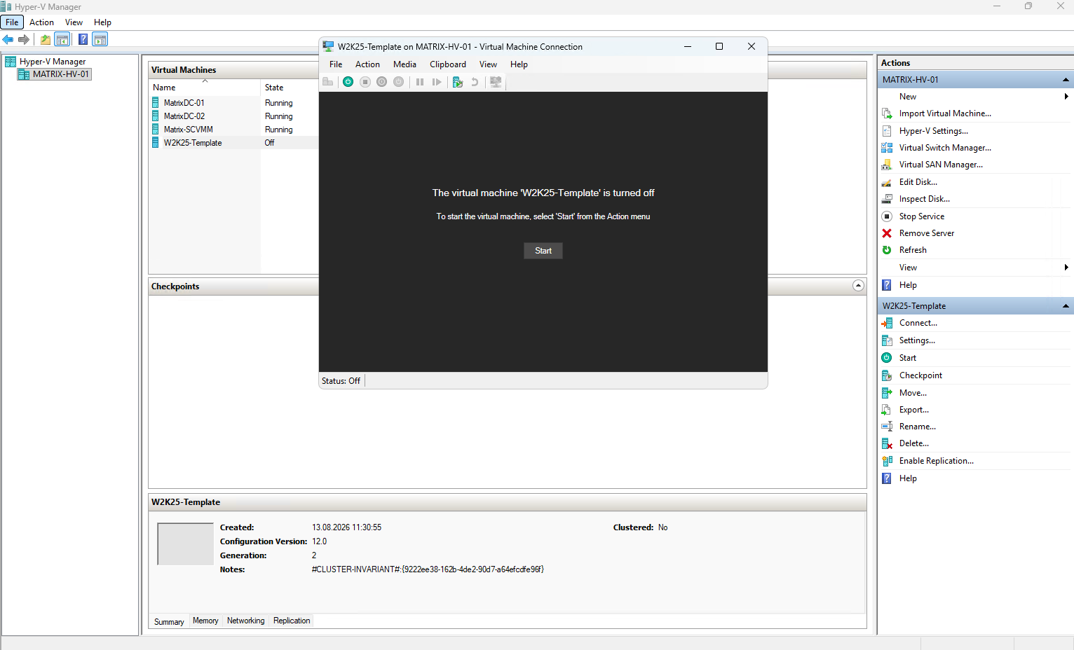
Do not boot the VM again after Sysprep
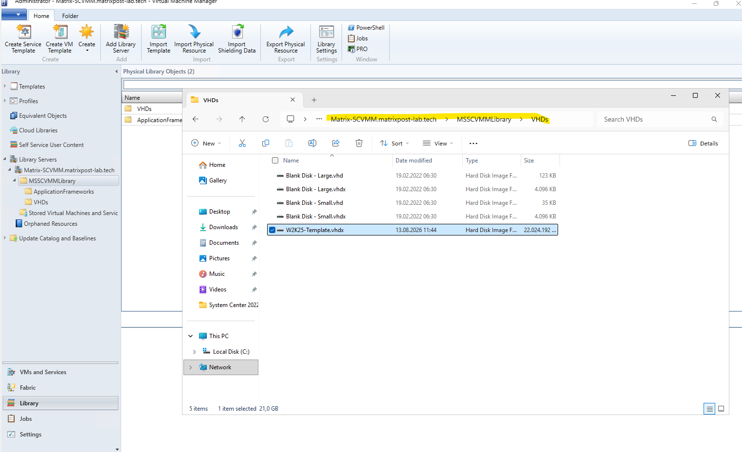
Copy its .vhdx into your existing MSSCVMMLibrary share. Microsoft says you can simply open the Library share via Library → Library Servers → right-click the share → Explore and copy the VHDX there. VMM’s library refresher will then discover it.
Source: https://learn.microsoft.com/en-us/system-center/vmm/library-files
Open the SCVMM Library share and copy the generalized W2K25-Template.vhdx into the library, for example into the existing VHDs folder. SCVMM periodically refreshes its library catalog, or we can trigger a refresh separately, after which the VHDX becomes available as a library resource.
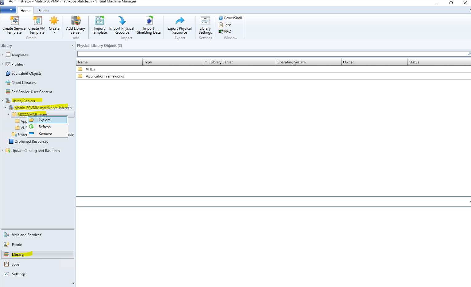
Copy the vhdx.
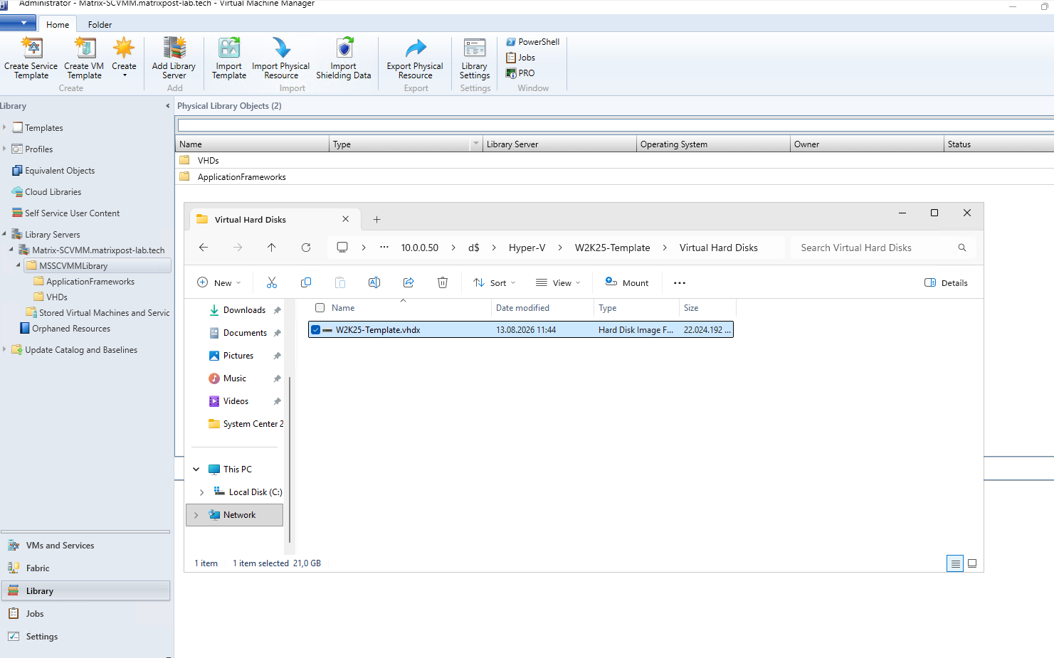
Open the SCVMM Library share and navigate to its VHDs folder. Copy our generalized W2K25-Template.vhdx into this folder so that it becomes part of the physical resources stored in the SCVMM Library.
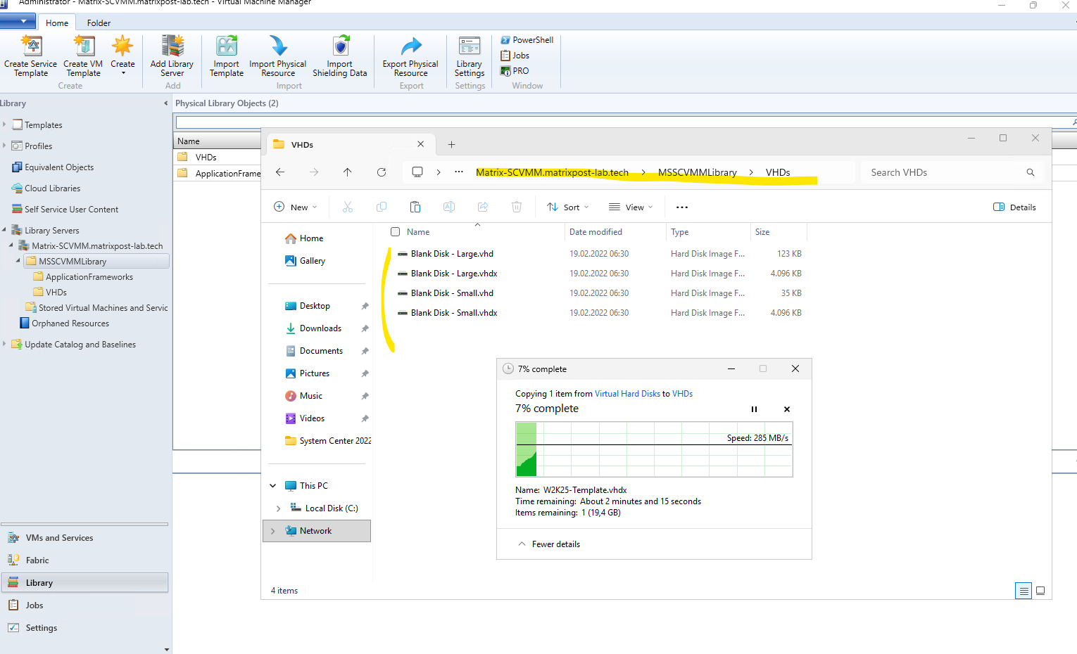
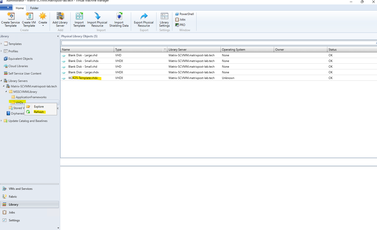
After copying the VHDX into the VHDs folder, right-click the folder in the SCVMM Library and select Refresh.
SCVMM rescans the library location and, once the refresh completes, our W2K25-Template.vhdx appears as a VHDX library resource with status OK.
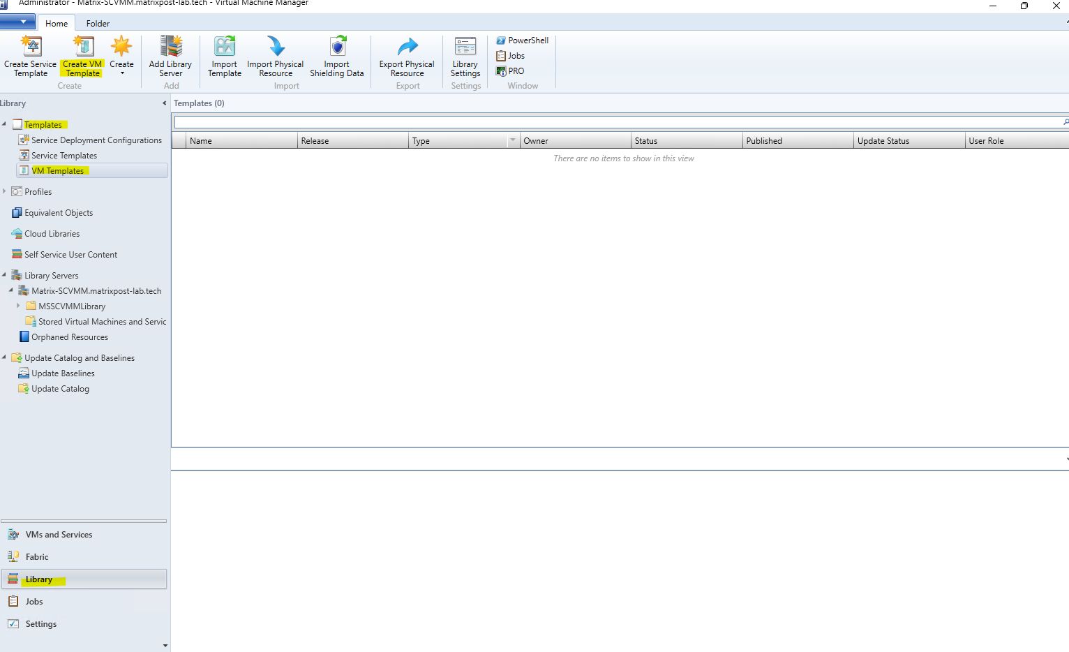
Next go to Library → Templates → VM Templates in SCVMM and select Create VM Template from the ribbon.
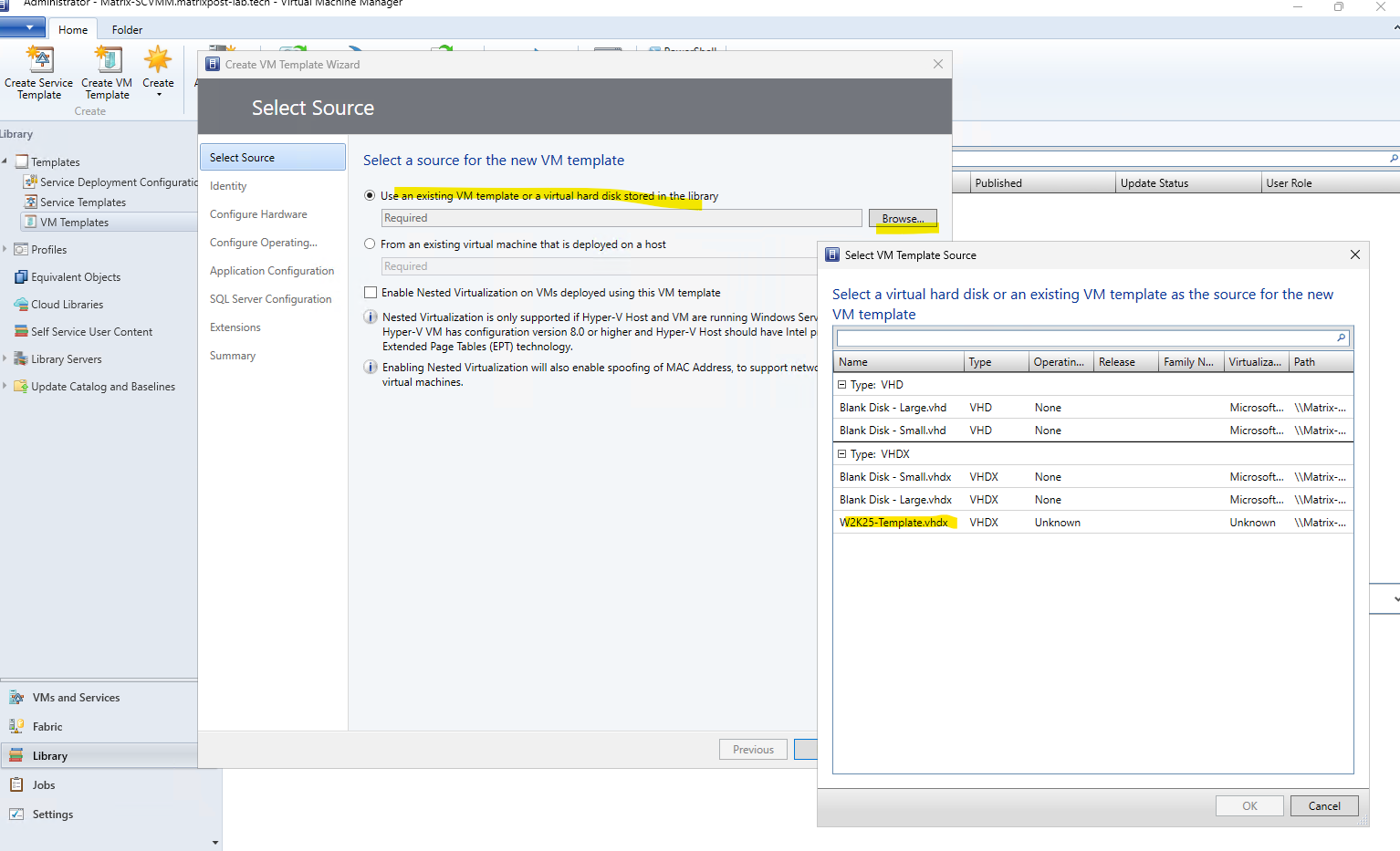
On the Select Source page, select Use an existing VM template or a virtual hard disk stored in the library, click Browse, and select our newly added W2K25-Template.vhdx.
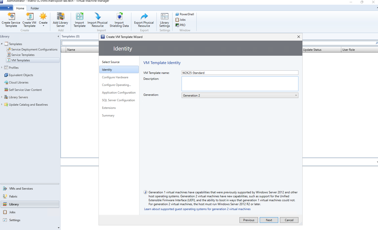
Enter a descriptive name for the new template, in our case W2K25-Standard. Since our generalized Windows Server 2025 VHDX was created from a Generation 2 VM, select Generation 2 here as well, providing modern VM capabilities such as UEFI firmware and Secure Boot.
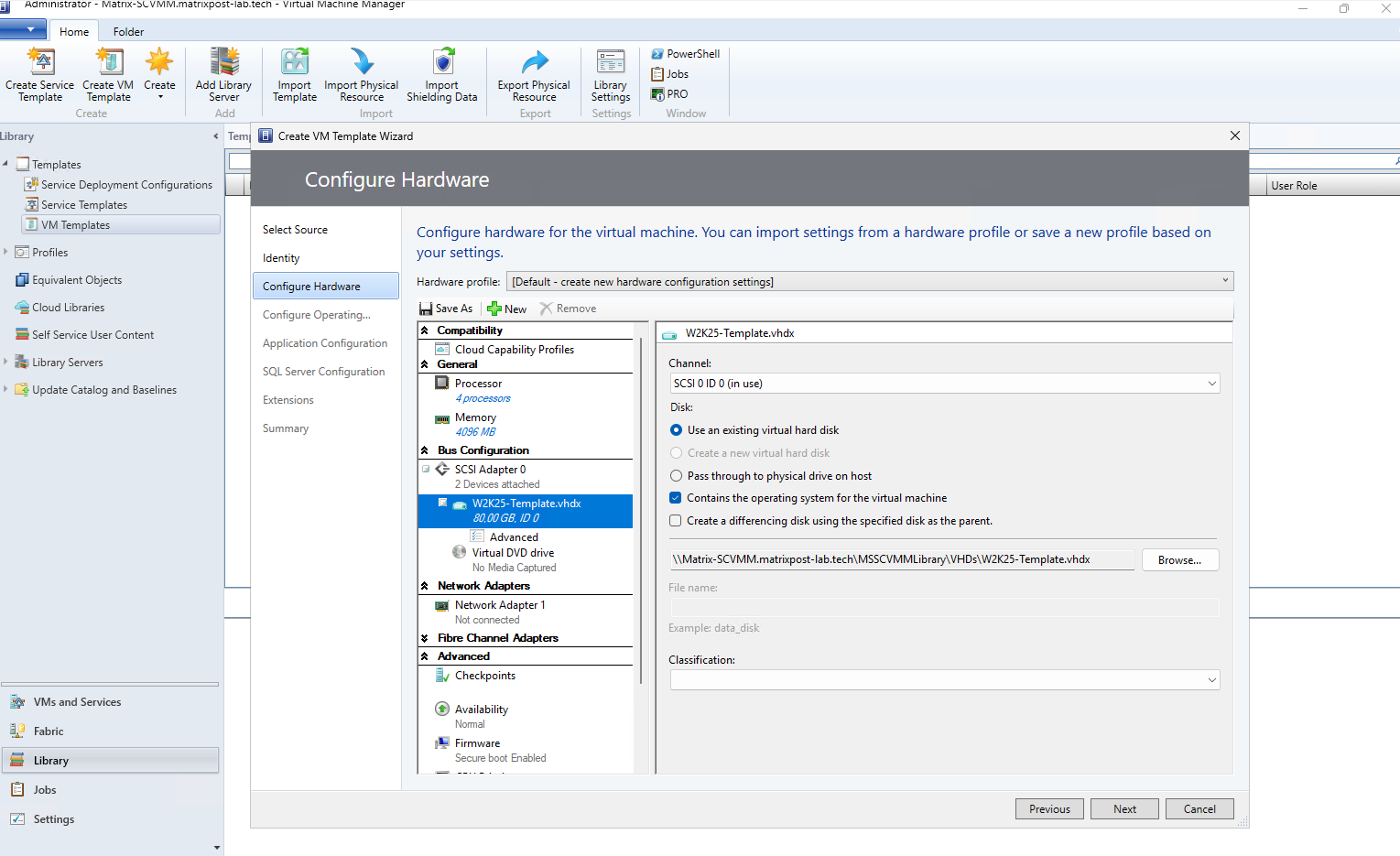
In the Configure Hardware step, we define the hardware configuration that will be used as the default for VMs deployed from this template, such as the number of virtual processors, memory, virtual disks, network adapters, and firmware settings. The imported W2K25-Template.vhdx is already attached as the operating system disk, while the remaining hardware can be adjusted according to our deployment requirements.
Since we want to keep the VM template reusable, we leave the network adapter Not connected. The appropriate SCVMM VM Network will be selected later when deploying a virtual machine from the template. Network connectivity is primarily required while preparing the source VM, for example to install Windows Updates or additional software before running Sysprep.
In vSphere, a template can simply be converted back into a virtual machine, updated or customized, shut down, and converted into a template again.
SCVMM does not provide the same direct workflow; instead, the usual approach is to deploy a VM from the template, apply the required updates or changes, run Sysprep again, and use the resulting generalized VHDX to update or recreate the VM template.
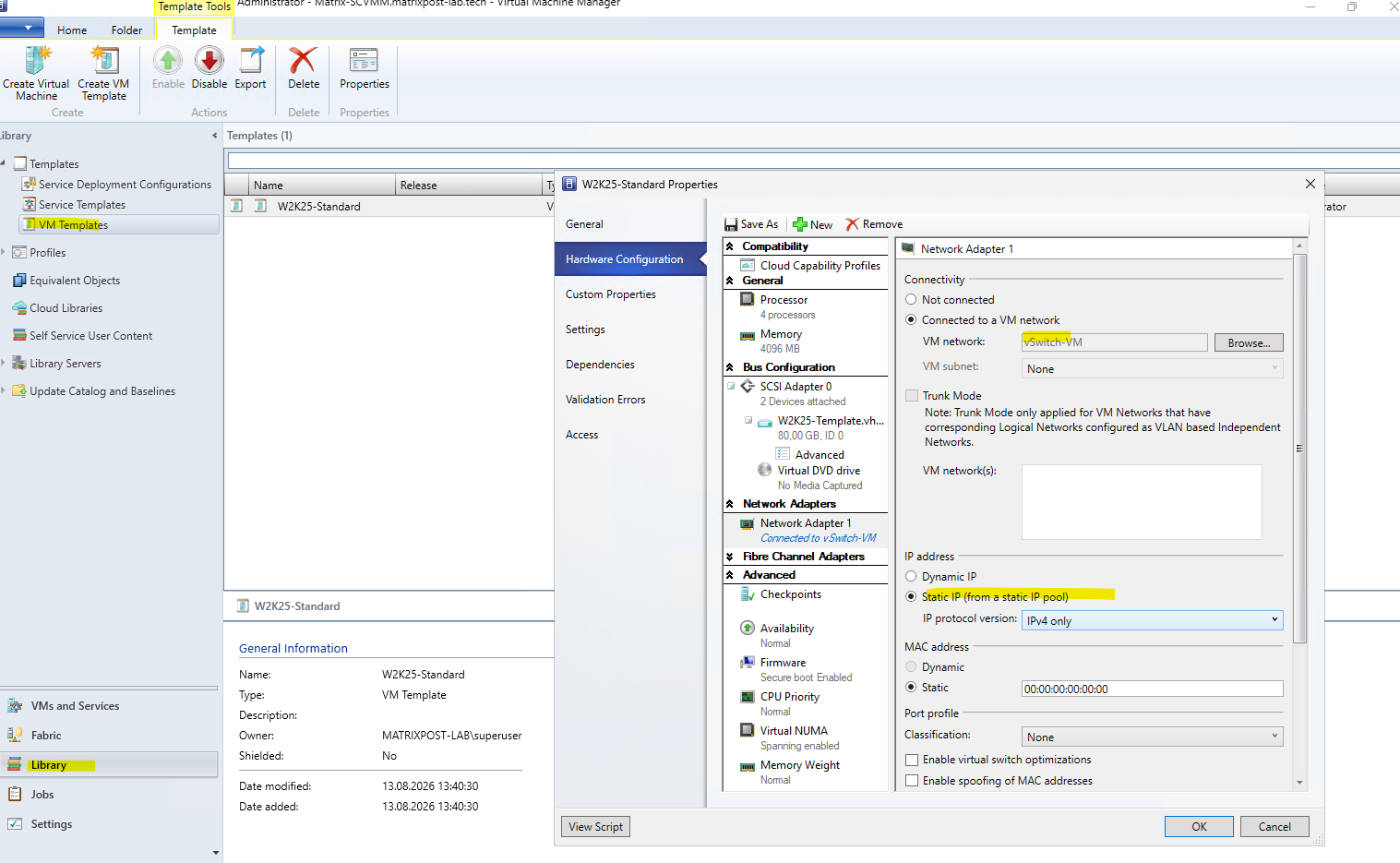
SCVMM can also automatically assign static IP addresses to virtual machines from a centrally managed Static IP Address Pool. This can be configured on the template’s virtual network adapter by selecting Static IP (from a static IP pool).
In this lab, however, we will leave the template configured for Dynamic IP and continue using traditional network configuration such as DHCP or manually assigned static IP addresses. The SCVMM IP pool functionality is shown here mainly to demonstrate the additional network automation capabilities available when deploying VMs from templates.
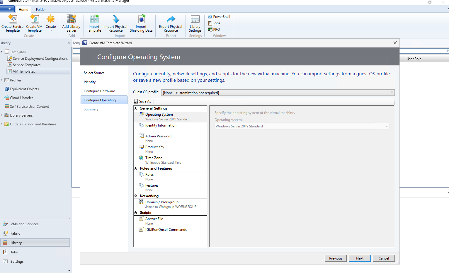
We can also switch the Guest OS profile from None – customization not required to create a new customization profile. However, Windows Server 2025 is not available as a guest operating system in SCVMM 2022, and for our current template we do not require any of these guest OS customization settings, so we simply leave the default settings unchanged and skip this step.
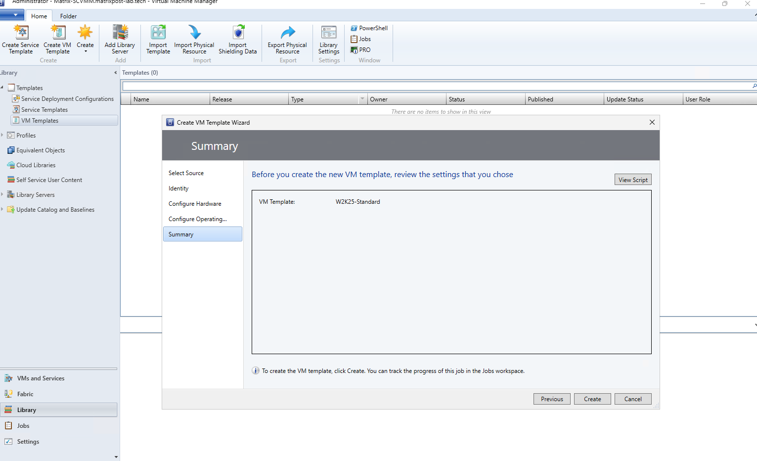
Finally, the Summary page shows the VM template that will be created with the selected configuration. Click Create to create our W2K25-Standard template; the creation process can then be monitored in the Jobs workspace.
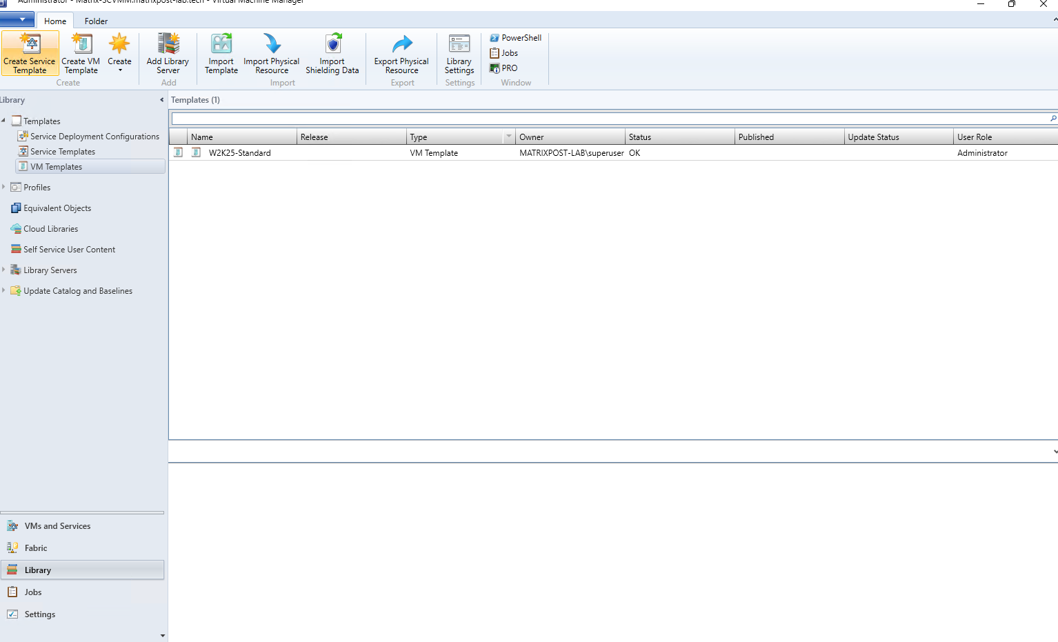
The W2K25-Standard VM template has now been successfully created and is shown in the SCVMM Library with the status OK. We can now use this template as the basis for deploying our first Windows Server 2025 virtual machine and assign the required VM Network during deployment.
Creating and Deploying a VM from the Template using the SCVMM Network
With our W2K25-Standard VM template ready, we can now deploy our first Windows Server 2025 virtual machine and connect it to the SCVMM-managed VM Network created earlier.
This also allows us to demonstrate how SCVMM combines template-based deployment with centralized network configuration and automatic static IP assignment from our IP Pool.
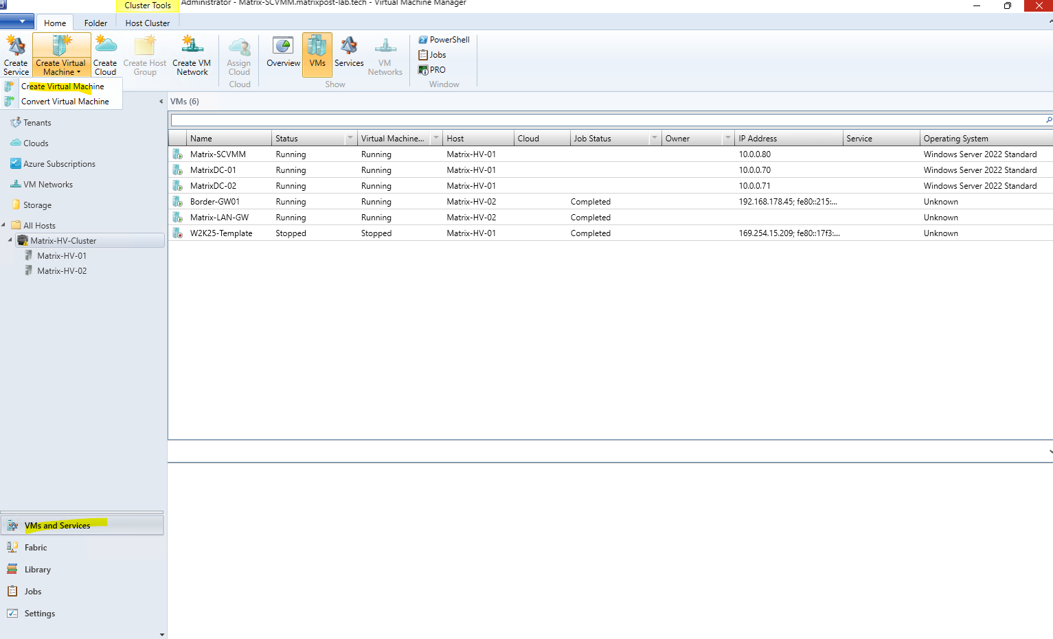
Go to VMs and Services, select the Matrix-HV-Cluster, and click Create Virtual Machine → Create Virtual Machine in the ribbon.
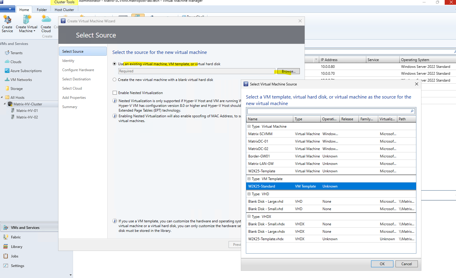
This starts the Create Virtual Machine Wizard, where we can select our previously created W2K25-Standard template and then configure the VM-specific settings, including its connection to our SCVMM-managed VM Network.
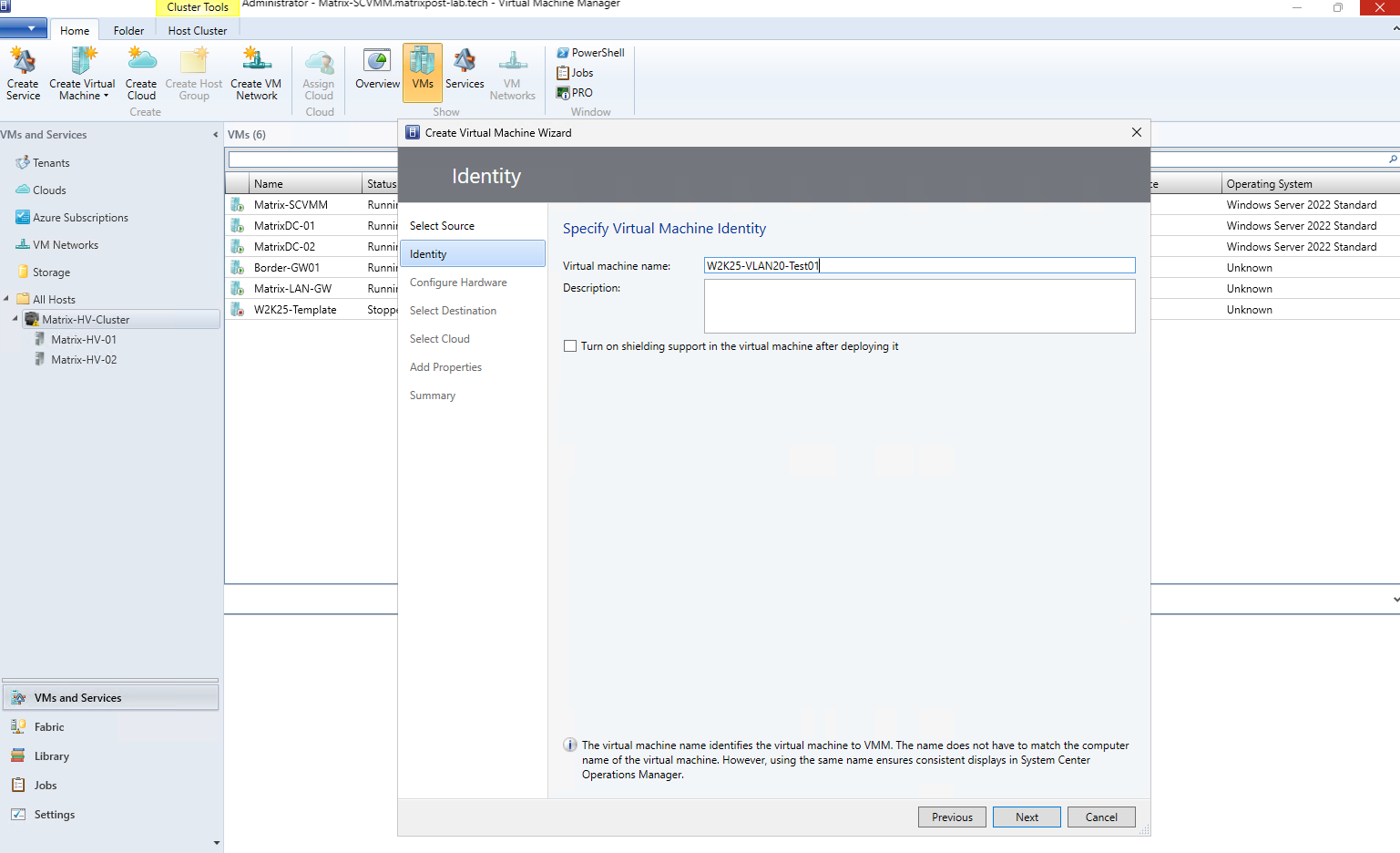
On the Identity page, enter a unique name for the new virtual machine. This is the name used by SCVMM to identify and manage the VM and does not necessarily have to match the Windows computer name configured inside the guest operating system.
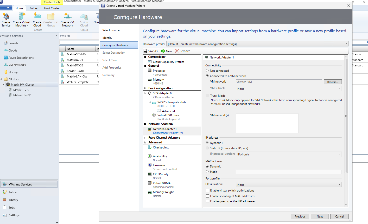
In Configure Hardware, we can review and adjust the hardware settings inherited from the VM template, such as the number of processors, memory, virtual disks, and network adapters.
Here we also connect the VM to the required VM Network, while keeping the IP configuration dynamic so that addressing can be handled by DHCP or configured manually later.
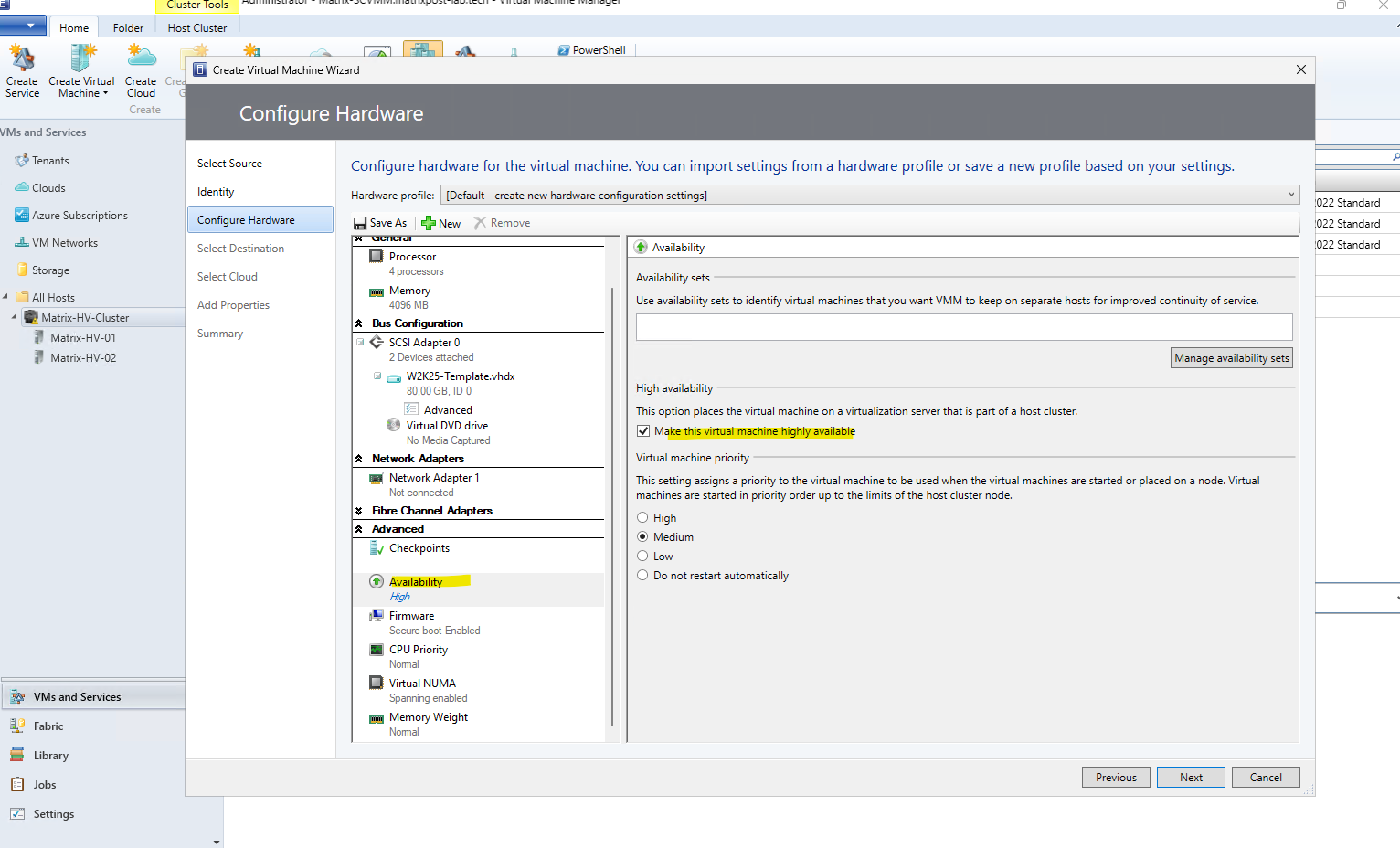
Because we want to make the new virtual machine highly available, we enable Make this virtual machine highly available under Advanced → Availability. This also allows the VM to be stored on our Cluster Shared Volume (CSV) and managed as a clustered VM.
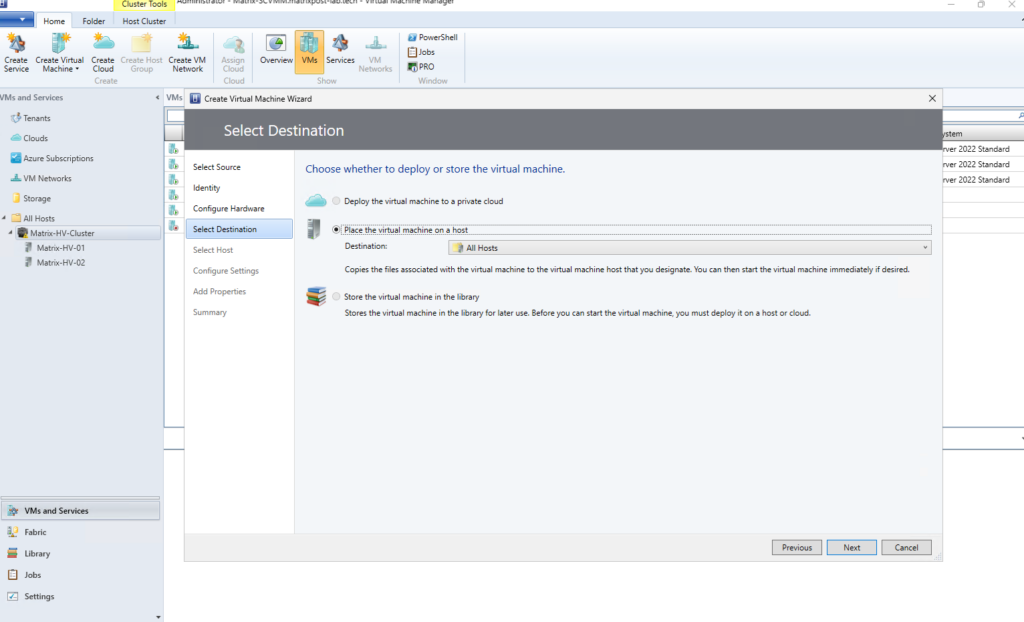
Next, under Select Destination, we choose where the new virtual machine should be deployed. In our case, we select Place the virtual machine on a host and use the All Hosts host group, allowing SCVMM to determine a suitable Hyper-V host in the next step.
SCVMM now evaluates the available Hyper-V hosts and calculates a placement rating based on the VM requirements, available resources, and configured placement settings. We can review any warnings and the rating details before selecting the preferred host for deployment.
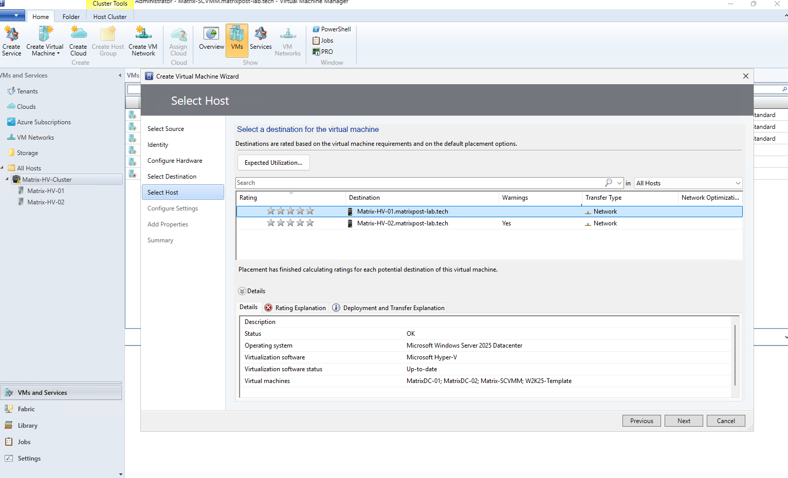
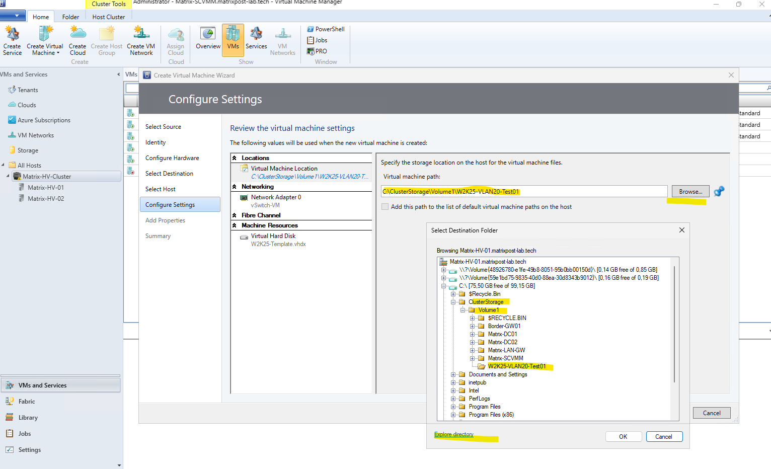
Under Configure Settings, we can review and adjust the deployment-specific configuration of the new VM. Here we select the Cluster Shared Volume (CSV) as the storage location and create/use a dedicated folder for the VM, while SCVMM also shows the network adapter and virtual disk that will be deployed.
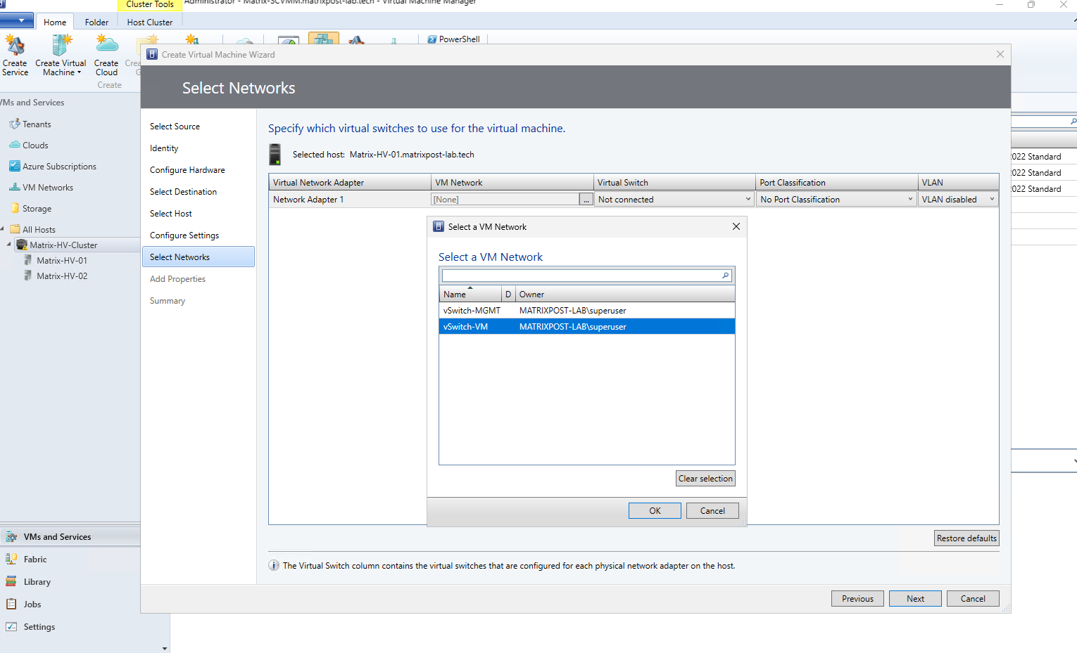
Because we enabled Make this virtual machine highly available, the wizard now includes the additional Select Networks step.
Here we can map the VM’s virtual network adapter to the appropriate SCVMM VM Network and corresponding virtual switch. In our case, we select vSwitch-VM, which is the logical VM network intended for the
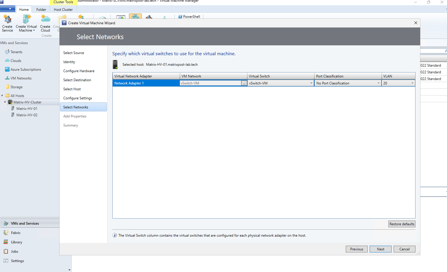
After selecting vSwitch-VM as the VM Network, SCVMM automatically resolves the corresponding vSwitch-VM virtual switch and VLAN 20 from the logical network configuration. This ensures that the VM is connected to the correct VLAN consistently across the Hyper-V cluster.
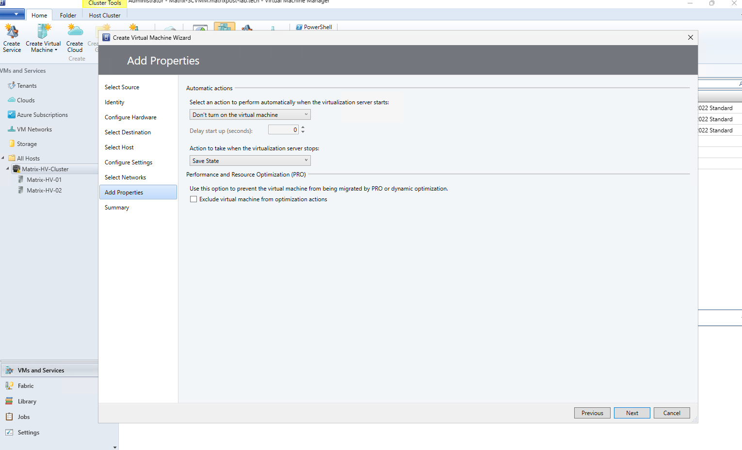
Under Add Properties, we can define the VM’s automatic start and stop behavior on the Hyper-V host. We can also exclude the VM from Performance and Resource Optimization (PRO) or Dynamic Optimization actions if required; for our deployment, we simply keep the defaults.
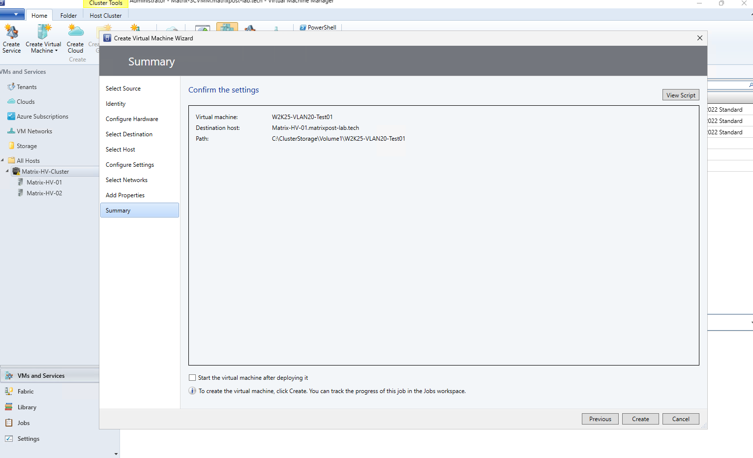
Finally, review the Summary, including the VM name, selected destination host, and CSV storage path. Optionally enable Start the virtual machine after deploying it, then click Create to begin the deployment; the progress can be monitored in the Jobs workspace.
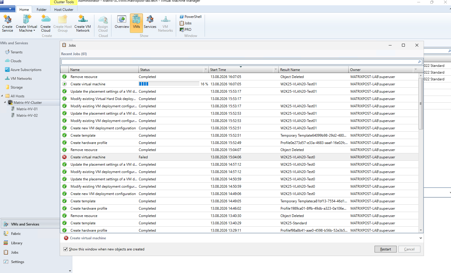
After confirming the configuration, SCVMM starts the deployment as a background job. The complete deployment process and its individual steps can be monitored in the Jobs workspace, including any warnings or errors that occur during VM creation.
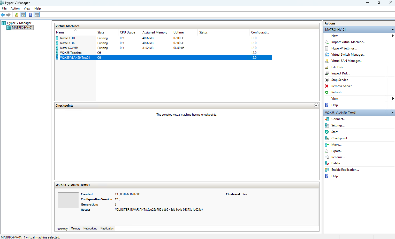
While the deployment job is still running in SCVMM, the new virtual machine is already visible in Hyper-V Manager on the selected cluster node.
We can also see that the VM is already registered as Clustered: Yes, while SCVMM continues completing the remaining deployment steps in the background.
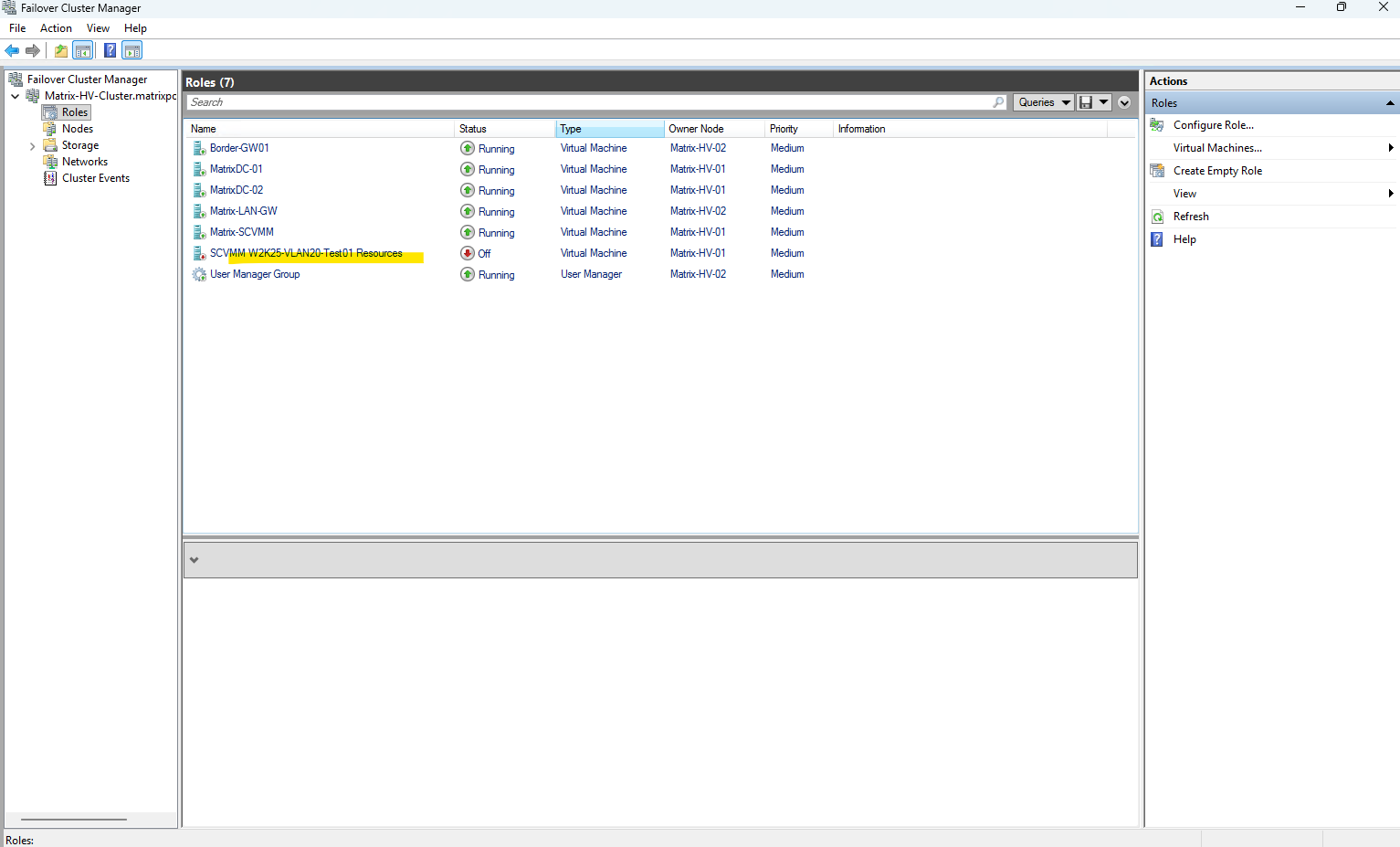
At the same time, the new virtual machine is already visible in Failover Cluster Manager under Roles.
Because we enabled Make this virtual machine highly available during deployment, SCVMM automatically registers the VM as a clustered role, allowing it to fail over between the Hyper-V cluster nodes.
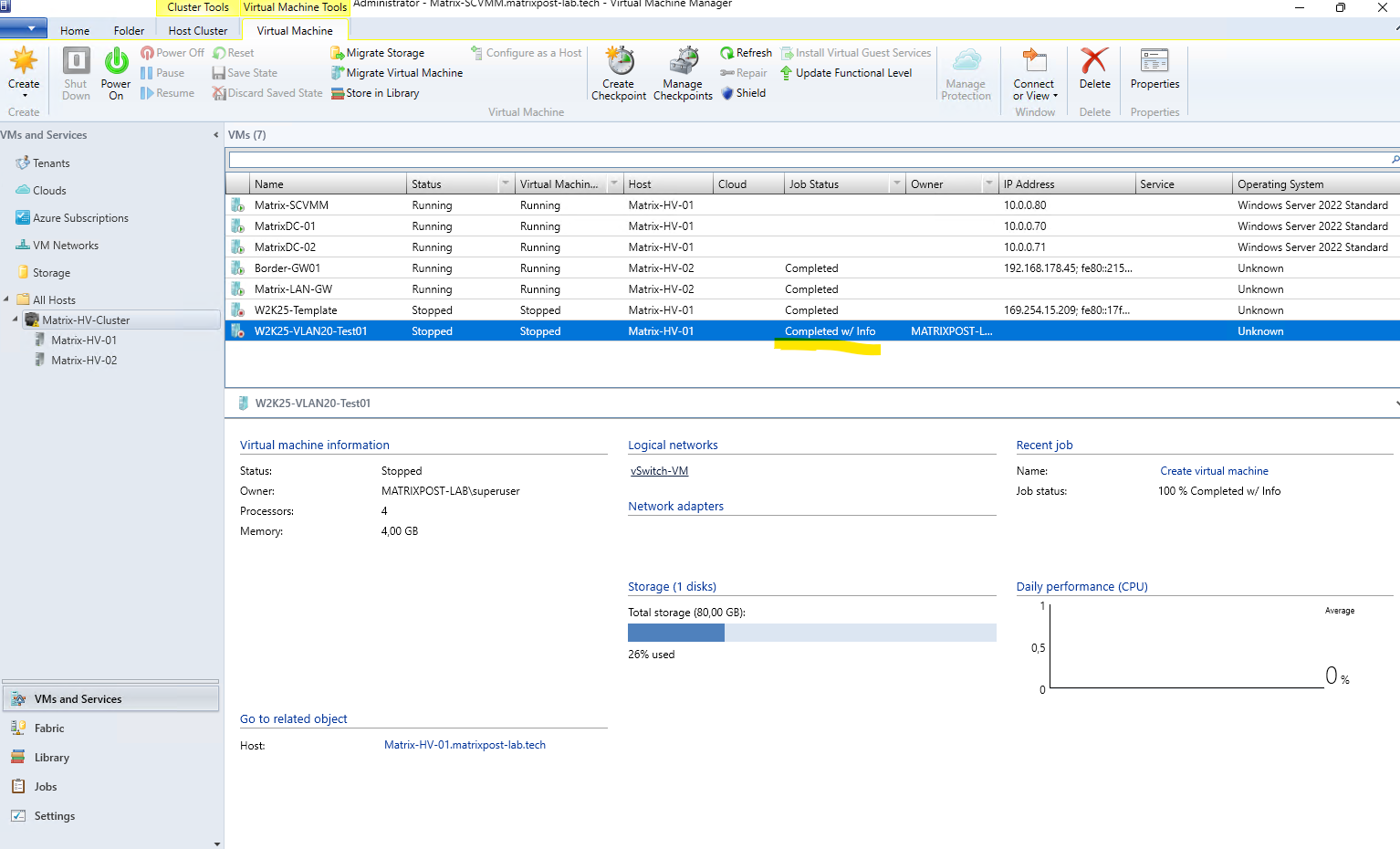
And finally the deployment has completed successfully. The new W2K25-VLAN20-Test01 VM is now listed in SCVMM with the job status Completed w/ Info and is managed as part of our Hyper-V cluster.
SCVMM vs. VMware vCenter
Finally, we will compare System Center Virtual Machine Manager (SCVMM) with VMware vCenter Server and look at the similarities and differences between the two approaches to centralized virtualization management.
Both platforms provide a central management layer for virtualization environments, but their underlying concepts and terminology differ considerably. The following comparison should help VMware administrators in particular map familiar vCenter concepts to their corresponding SCVMM and Hyper-V components.
| VMware vSphere / vCenter | Microsoft Hyper-V / SCVMM | Purpose / Notes |
|---|---|---|
| vCenter Server | SCVMM Server | Centralized management platform for virtualization hosts, clusters, VMs, networking, and storage. |
| vSphere Client | Virtual Machine Manager Console | Primary graphical administration interface. |
| ESXi Host | Hyper-V Host | Physical virtualization host running the VMs. |
| vSphere Cluster | Windows Server Failover Cluster | Groups multiple virtualization hosts to provide high availability and workload mobility. |
| vSphere HA | Failover Clustering | Automatically restarts VMs on another host following a host failure. |
| vMotion | Live Migration | Moves a running VM between hosts with little or no service interruption. |
| Storage vMotion | Storage Migration | Moves VM storage while the VM remains available. |
| DRS | Dynamic Optimization | Balances workloads across hosts based on available resources and placement requirements. |
| Storage DRS | Dynamic Optimization / Storage Optimization concepts | Storage placement and optimization exist in SCVMM, although the architecture and capabilities are not a direct equivalent of VMware Storage DRS. |
| Datastore | Storage / CSV | Storage used for VM configuration files and virtual disks. In a Failover Cluster, Cluster Shared Volumes (CSV) provide shared storage accessible by all cluster nodes. |
| VMFS Datastore | CSV with NTFS/ReFS | Cluster-accessible filesystem/storage used to hold VM files. The underlying implementations are fundamentally different. |
| VMDK | VHDX | Virtual hard disk format. |
| vSphere Distributed Switch (vDS) | SCVMM Logical Switch | Centrally defines and consistently deploys virtual networking configuration across virtualization hosts. |
| Physical NIC / vmnic | Physical Network Adapter | Physical host network interface used as an uplink. |
| Distributed Port Group | VM Network / Port Classification | Provides logical network connectivity and policies for VM network adapters. The mapping is conceptual rather than strictly 1:1. |
| VLAN-backed Port Group | Logical Network + Network Site + VM Network | SCVMM separates the physical/logical network definition, VLAN/subnet information, and VM-facing network into several objects. |
| vDS Uplink | Uplink Port Profile | Defines how physical adapters connect the host to the logical networking infrastructure. |
| NIC Teaming on vDS | SET / Logical Switch Uplink configuration | Provides multiple physical adapters for redundancy and load distribution. |
| VM Template | VM Template | Reusable definition for deploying standardized virtual machines. |
| Content Library | SCVMM Library | Central repository for templates, virtual disks, ISO images, scripts, and other deployment resources. |
| Customization Specification | Guest OS Profile / VM Template OS Configuration | Automates guest OS configuration during VM deployment. |
| Host Profile | Host Profile / Physical Computer Profile concepts | Used to standardize host deployment and configuration, although the implementations differ significantly. |
| Resource Pool | Host Group / Cloud / resource controls | SCVMM organizes and delegates infrastructure differently; there is no exact equivalent to the vSphere resource-pool hierarchy. |
| Datacenter | Host Group | Logical organization of hosts and clusters. Again, not a strict 1:1 mapping. |
| Tags / Categories | Custom Properties | Metadata that can be associated with managed objects and used for organization or automation. |
| Lifecycle Manager (vLCM) | Update Management integration | Host servicing and lifecycle management. Modern Microsoft environments increasingly rely on Windows servicing/Azure management rather than an exact SCVMM equivalent to vLCM. |
| Tasks / Events | Jobs | Tracks administrative operations and provides detailed status and error information. |
| Permissions / Roles | User Roles / Run As Accounts | Role-based access and delegated administration of the virtualization environment. |
Administrators coming from VMware vSphere will recognize many of the same fundamental concepts in Hyper-V and SCVMM, including centralized host and VM management, clusters, high availability, live migration, templates, shared storage, and centrally managed networking. The biggest difference is often not the functionality itself, but how Microsoft divides these functions between Windows Server, Failover Clustering, Hyper-V, and SCVMM.
VMware generally presents these components through a tightly integrated vSphere/vCenter architecture, whereas the Microsoft stack builds on several Windows Server technologies and adds SCVMM as the centralized management and orchestration layer. Once these relationships and the different terminology are understood, many familiar vSphere administration concepts translate quite naturally to a Hyper-V environment.
Links
Plan for Hyper-V networking in Windows Server
https://learn.microsoft.com/en-us/windows-server/virtualization/hyper-v/plan/plan-hyper-v-networking-in-windows-serverHyper-V Virtual Switch
https://learn.microsoft.com/en-us/windows-server/virtualization/hyper-v/virtual-switchNetwork recommendations for Hyper-V in a failover cluster
https://learn.microsoft.com/en-us/windows-server/virtualization/hyper-v/failover-cluster-network-recommendationsSwitch Embedded Teaming (SET)
https://learn.microsoft.com/en-us/azure/azure-local/concepts/host-network-requirements/#switch-embedded-teaming-setHyper-V virtualization in Windows Server and Windows
https://learn.microsoft.com/en-us/windows-server/virtualization/hyper-v/overviewHyper-V Architecture
https://learn.microsoft.com/en-us/windows-server/virtualization/hyper-v/architecturePlan for Hyper-V security in Windows Server
https://learn.microsoft.com/en-us/windows-server/virtualization/hyper-v/plan/plan-hyper-v-security-in-windows-serverInstall Hyper-V
https://learn.microsoft.com/en-us/windows-server/virtualization/hyper-v/get-started/install-hyper-vWhat is Nested Virtualization?
https://learn.microsoft.com/en-us/windows-server/virtualization/hyper-v/nested-virtualizationHyper-V Virtual Fibre Channel
https://learn.microsoft.com/en-us/windows-server/virtualization/hyper-v/plan/virtual-fibre-channel-for-hyper-vGuarded fabric and shielded VMs
https://learn.microsoft.com/en-us/windows-server/security/guarded-fabric-shielded-vm/guarded-fabric-and-shielded-vms-top-nodeCluster Shared Volume goes offline after a node or storage component goes offline
https://learn.microsoft.com/en-us/troubleshoot/windows-server/high-availability/csv-offline-after-component-goes-offline-during-active-ioSet-SCLogicalSwitch
https://learn.microsoft.com/en-us/powershell/module/virtualmachinemanager/set-sclogicalswitchNetwork QoS minimum bandwidth best practices for Hyper-V
https://learn.microsoft.com/en-us/windows-server/virtualization/hyper-v/network-quality-of-service-bandwidth-limitsNew-VMSwitch
https://learn.microsoft.com/en-ca/powershell/module/hyper-v/new-vmswitchSet up VM networks in the VMM fabric
https://learn.microsoft.com/en-us/system-center/vmm/network-virtualAdd file-based resources to the VMM library
https://learn.microsoft.com/en-us/system-center/vmm/library-files