Step-by-Step Guide: Setting up a route-based S2S IPSec VPN Tunnel between Azure and On-Premise by using the Juniper vSRX3 Appliance for the on-premise VPN Device
Setting up a site-to-site VPN tunnel between an on-premises Juniper vSRX firewall and Microsoft Azure can feel a bit like piecing together a puzzle, especially when dealing with dynamic DNS, NAT traversal, and vendor-specific quirks.
Whether you’re deploying for production, lab testing (as in my case), or just expanding your hybrid networking skills, this guide walks you through the full configuration using both JunOS CLI and the Web UI.
We will see step-by-step how to set up a route-based IPSec VPN, sharing all the commands and GUI settings needed to get a fully operational tunnel including working traffic between your on-prem and Azure resources.
About how to setup the Juniper vSRX3 appliance with the initial setup and network interface assignment and configuration to allow outbound internet access for internal hosts, you can also read my following post.
It also shows how to publish internal services like a web server to the Internet.
My Juniper vSRX finally sits behind my NAT router (FRITZ!Box) in this home network lab scenario and has not assigned directly a public IP. More about using therefore a NAT router (FRITZ!Box), you will find in my following post.
Our VPN Software/VPN Gateway, here Juniper vSRX, needs to support and use NAT traversal (i.e. the encapsulation of ESP in UDP packets).
Introduction
In this post, we’ll pick up where my previous post left off, where we deployed and configured the Juniper vSRX3 as a basic firewall to provide outbound internet access for internal hosts and how to publish internal services to the internet.
We’ll now extend that setup by establishing a route-based IPSec VPN tunnel between the vSRX3 and an Azure VPN Gateway, assuming the core interfaces, zones, and trust/untrust policies are already in place as shown in my previous post.
Below we will see first how to set up the tunnel in Juniper OS by using the CLI and then later also by using the Web UI.
About how to set up the tunnel in Azure step by step you can read in my following post. Here I was also configuring BGP on both sites to advertise automatically routes between both sites. In this post I will not configure BGP and therefore just configure static routes. Below you will find my next post about how to also configure BGP here.
About how to enable and configure BGP on Juniper vSRX3 as mentioned, you can read my following next post.
Set up the Tunnel by using the CLI
I have already set up the tunnel in Azure, therefore I will first need to determine the IKE an IPSec proposals in Azure to be sure to use the same on my Juniper appliance.
We will find them directly on the connection object in Azure.
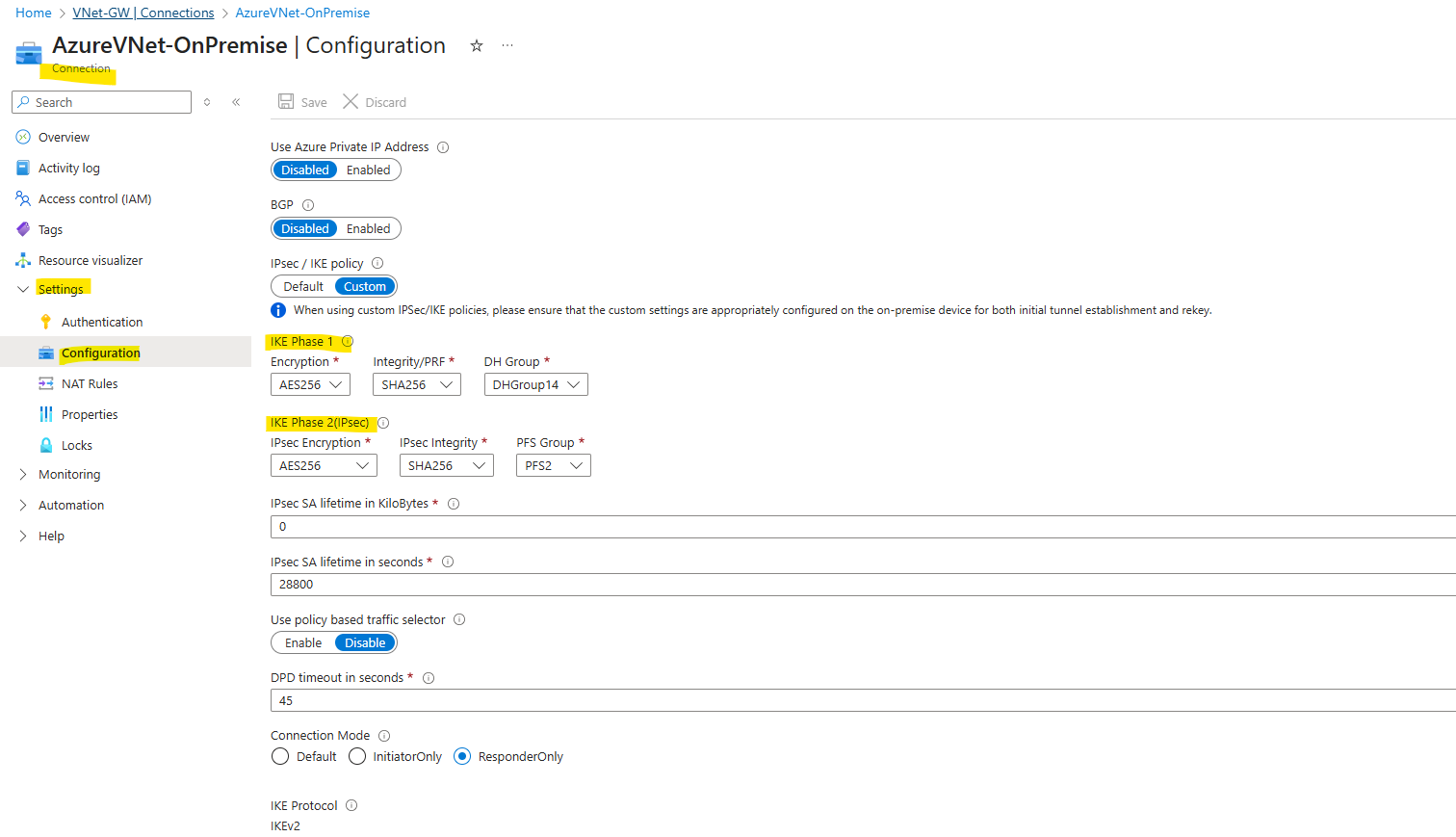
Below we will see the IKE an IPSec proposals for Juniper which finally will match with my Azure proposals.
One of the more confusing aspects when setting up a site-to-site VPN between Juniper vSRX and Azure is the difference in terminology and structure around IPsec and IKE configuration.
Both platforms use different naming conventions.
Here’s how Azure’s terminology (used in my configuration) maps to Juniper’s syntax:
IKE (Phase 1)
| Setting | Azure Name | Juniper Name (set security ike proposal) |
|---|---|---|
| Encryption | AES256 | encryption-algorithm aes-256-cbc |
| Integrity / PRF | SHA256 | authentication-algorithm sha-256 |
| DH Group | DH Group 14 (2048-bit) | dh-group group14 |
| Lifetime | 28,800 seconds (8 hours) | lifetime-seconds 28800 |
| Auth Method | Pre-shared key | authentication-method pre-shared-keys |
IPsec (Phase 2)
| Setting | Azure Name | Juniper Name (set security ipsec proposal) |
|---|---|---|
| Encryption | AES256 | encryption-algorithm aes-256-cbc |
| Integrity | SHA256 | authentication-algorithm hmac-sha-256-128 |
| PFS (optional) | PFS2 | none |
| Lifetime | 28,800 seconds | lifetime-seconds 28800 |
Now let’s set up the tunnel on Juniper.
IKE Phase 1 (IKEv2)
We can commit just at the end and don’t need to do this after each section.
set security ike proposal AZURE_IKE_PROPOSAL authentication-method pre-shared-keys
set security ike proposal AZURE_IKE_PROPOSAL dh-group group14
set security ike proposal AZURE_IKE_PROPOSAL authentication-algorithm sha-256
set security ike proposal AZURE_IKE_PROPOSAL encryption-algorithm aes-256-cbc
set security ike proposal AZURE_IKE_PROPOSAL lifetime-seconds 28800

set security ike policy AZURE_IKE_POLICY proposals AZURE_IKE_PROPOSAL
set security ike policy AZURE_IKE_POLICY reauth-frequency 0

# adjust to your pre-shared key
set security ike policy AZURE_IKE_POLICY pre-shared-key ascii-text "<your_psk>"

set security ike gateway AZURE_IKE_GATEWAY ike-policy AZURE_IKE_POLICY
set security ike gateway AZURE_IKE_GATEWAY address <Azure_Public_IP>
set security ike gateway AZURE_IKE_GATEWAY no-nat-traversal   ## Important! Azure VPN Gateway sits not behind NAT

# for the local-identiy of Juniper I will use my dynDNS FQDN which is also set on the local gateway in Azure because of my home lab scenario with no fix/static public IP
set security ike gateway AZURE_IKE_GATEWAY local-identity hostname matrixpost.ddns.net

set security ike gateway AZURE_IKE_GATEWAY remote-identity inet <Azure_Public_IP>
set security ike gateway AZURE_IKE_GATEWAY external-interface ge-0/0/1.0
set security ike gateway AZURE_IKE_GATEWAY version v2-only
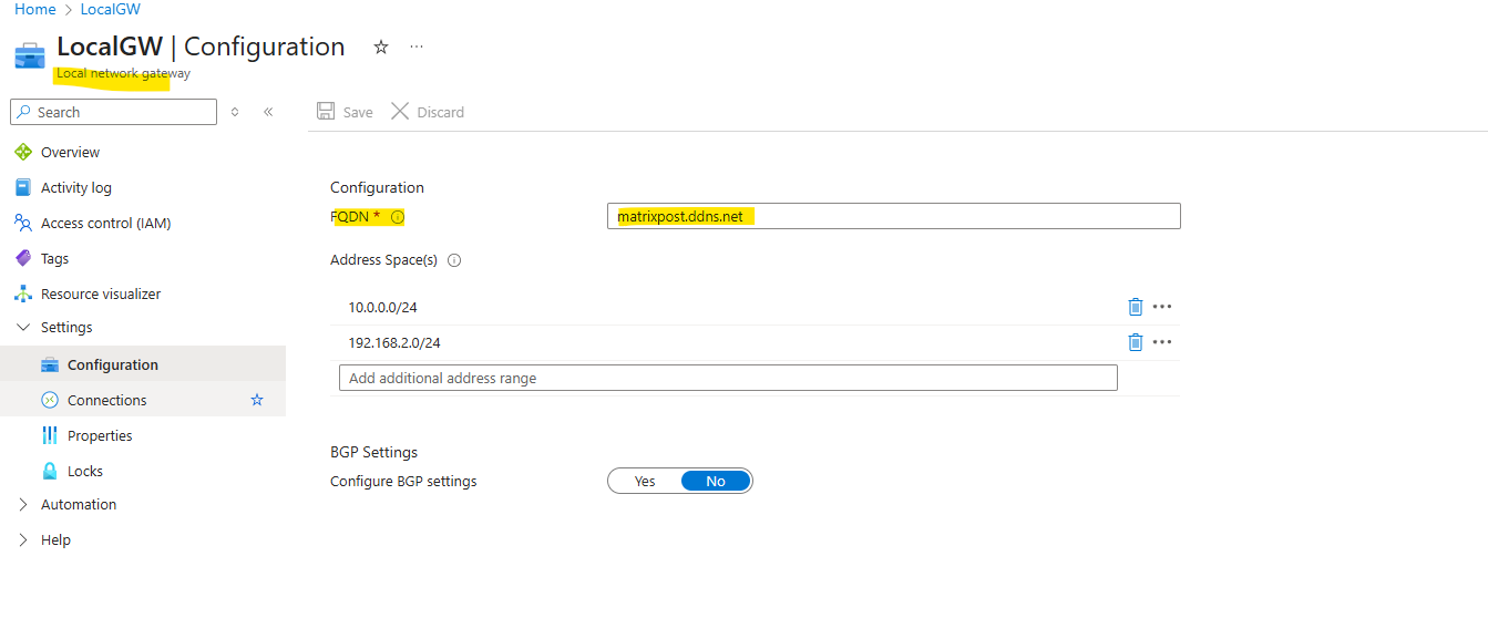
Here as mentioned in the commands above, for the local-identiy of Juniper I will use my dynDNS FQDN set below on the local gateway in Azure because of my home lab scenario with no fix/static public IP
set security ike gateway AZURE_IKE_GATEWAY local-identity hostname matrixpost.ddns.net
IPSec Phase 2
set security ipsec proposal AZURE_IPSEC_PROPOSAL protocol esp
set security ipsec proposal AZURE_IPSEC_PROPOSAL authentication-algorithm hmac-sha-256-128
set security ipsec proposal AZURE_IPSEC_PROPOSAL encryption-algorithm aes-256-cbc
set security ipsec proposal AZURE_IPSEC_PROPOSAL lifetime-seconds 28800

set security ipsec policy AZURE_IPSEC_POLICY proposals AZURE_IPSEC_PROPOSAL

set security ipsec vpn AZURE_VPN bind-interface st0.0
set security ipsec vpn AZURE_VPN ike gateway AZURE_IKE_GATEWAY
set security ipsec vpn AZURE_VPN ike ipsec-policy AZURE_IPSEC_POLICY
set security ipsec vpn AZURE_VPN establish-tunnels immediately
Tunnel Interface & Routing
The tunnel interface st0.0 we can leave unnumbered without a specific IP Address. An IP address we just need to assign when using BGP. More about the tunnel interface and assigning an IP address or not you will find in my following post.
In case we want to enable BGP between Juniper and Azure like shown in my post here, we will assign an IP address when enabling BGP.
In case of Azure, we cannot just use as usual the second BGP peer IP address from the dedicated /30 network we want to use for, as we would when using APIPA addresses therefore, the reason for is that this subnet finally is allocated by the VPN gateway subnet in Azure, therefore when we put one of those two IP addresses into the BGP peer IP address field (on-premise/Juniper BGP IP) on the local network gateway object, we would run into an address space overlap between two networks error, more in this post.
We just need to create the tunnel interface (unnumbered) and configure it as next hop for the Azure virtual network to route traffic destined to Azure through the tunnel.
# e.g. assign the second BGP peer IP address from Azure or as mentioned just leave it unnumbered
set interfaces st0 unit 0 family inet address 172.17.9.253/30

# to remove it again just run
delete interfaces st0 unit 0 family inet address 172.17.9.253/30


##### required to configure #####

# create the tunnel interface (unnumbered) if not already created numbered by running the first command above
set interfaces st0 unit 0 family inet          ## creates st0.0 (no IP)

# add a static routing for our Azure network is mandatory and needed
set routing-options static route 172.17.0.0/16 next-hop st0.0
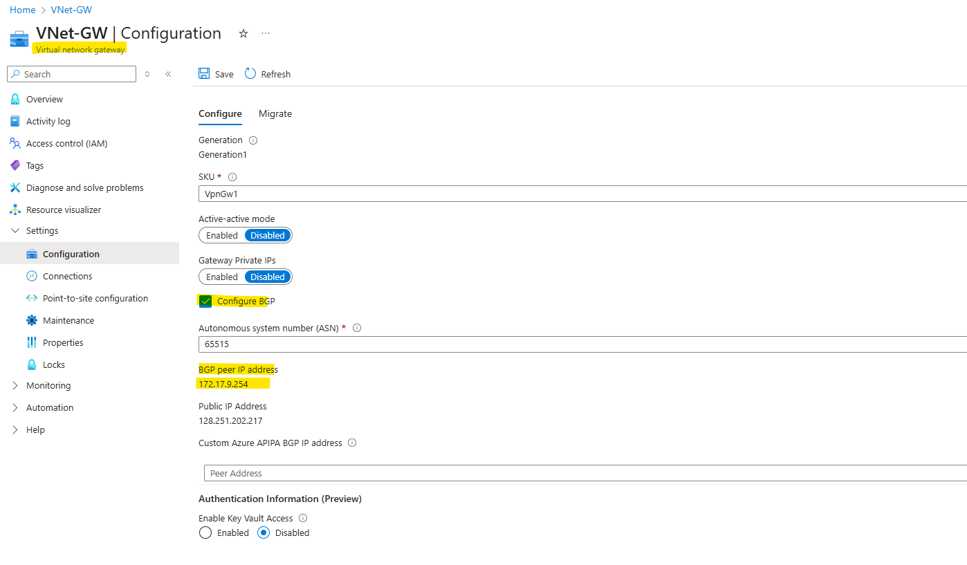
If you want to assign an IP address to the tunnel interface st0.0, you can determine which address you will have to use by checking temporarily Configure BGP as shown below.
So Azure is using in case of BGP here the IP address 172.17.9.254/30, which finally is allocated from the VPN Gateway subnet. Therefore we can use for the tunnel interface on Juniper the address 172.17.9.253/30.
But as mentioned not needed for static routing without BGP and explained here in detail.
Finally the IPSec/ESP phase 2 “forwarding engine” sees that interface is mapped to an active IPsec SA and encapsulates the packets directly into ESP for the remote peer.
Security Zones
set security zones security-zone vpn interfaces st0.0
set security zones security-zone trust interfaces ge-0/0/0.0
set security zones security-zone untrust interfaces ge-0/0/1.0
set security zones security-zone untrust screen untrust-screen
Security Policies
# Trust → VPN
set security policies from-zone trust to-zone vpn policy trust-to-azure match source-address any
set security policies from-zone trust to-zone vpn policy trust-to-azure match destination-address any
set security policies from-zone trust to-zone vpn policy trust-to-azure match application any
set security policies from-zone trust to-zone vpn policy trust-to-azure then permit

# VPN → Trust
set security policies from-zone vpn to-zone trust policy azure-to-trust match source-address any
set security policies from-zone vpn to-zone trust policy azure-to-trust match destination-address any
set security policies from-zone vpn to-zone trust policy azure-to-trust match application any
set security policies from-zone vpn to-zone trust policy azure-to-trust then permit
Logging & Debugging (optional but useful)
set system syslog file ike-log any any
set system syslog file ike-log match invalid
set security ike traceoptions file ike-debug
set security ike traceoptions file size 1m
set security ike traceoptions file files 5
set security ike traceoptions flag all
As already mentioned, finally we need to commit our new configuration.
root@junos-vsrx3# commit
Special Notes
Firewall policies are wide open between zones. You may want to restrict these for production.
Verifying VPN Tunnel Status on Juniper vSRX
Once the configuration is complete on both the Juniper and Azure sides, we can check if the tunnel is up and actively passing traffic.
Below are the key Juniper CLI commands to verify the IKE and IPsec tunnel status.
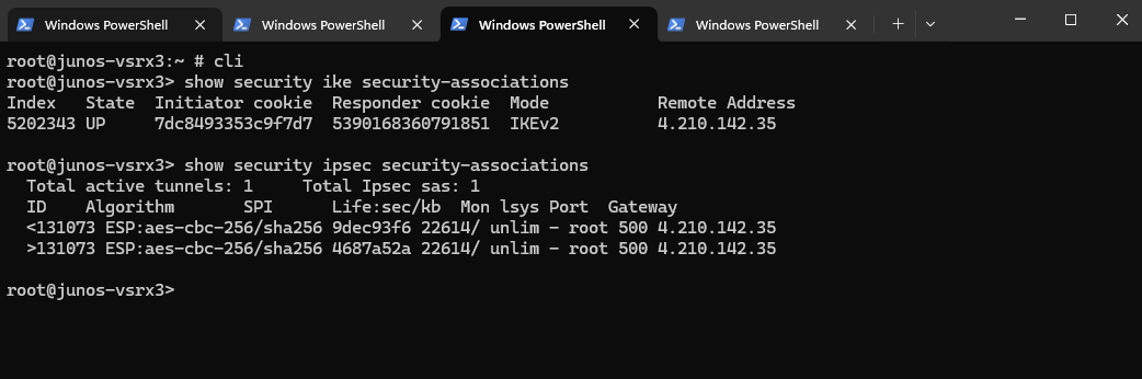
This shows if the IKEv2 negotiation has succeeded.
root@junos-vsrx3> show security ike security-associations
This confirms that the IPsec tunnel is established and ready to encrypt/decrypt traffic.
root@junos-vsrx3> show security ipsec security-associations
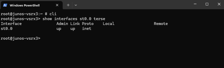
We can also verify the interface bindings and routing. Ensure the st0.0 interface (used by the VPN / aka VTI virtual tunnel interface) is up. (in case of unnumbered like here, no IP is assigned to.)
root@junos-vsrx3> show interfaces st0.0 terse
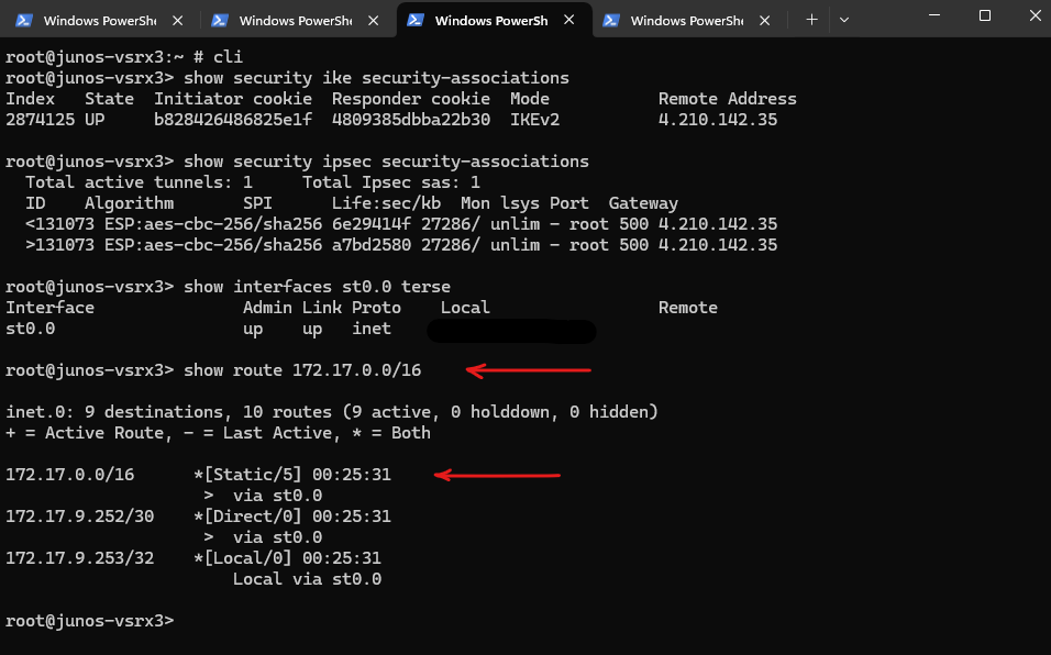
Check that the route to Azure is pointed via st0.0.
root@junos-vsrx3> show route 172.17.0.0/16
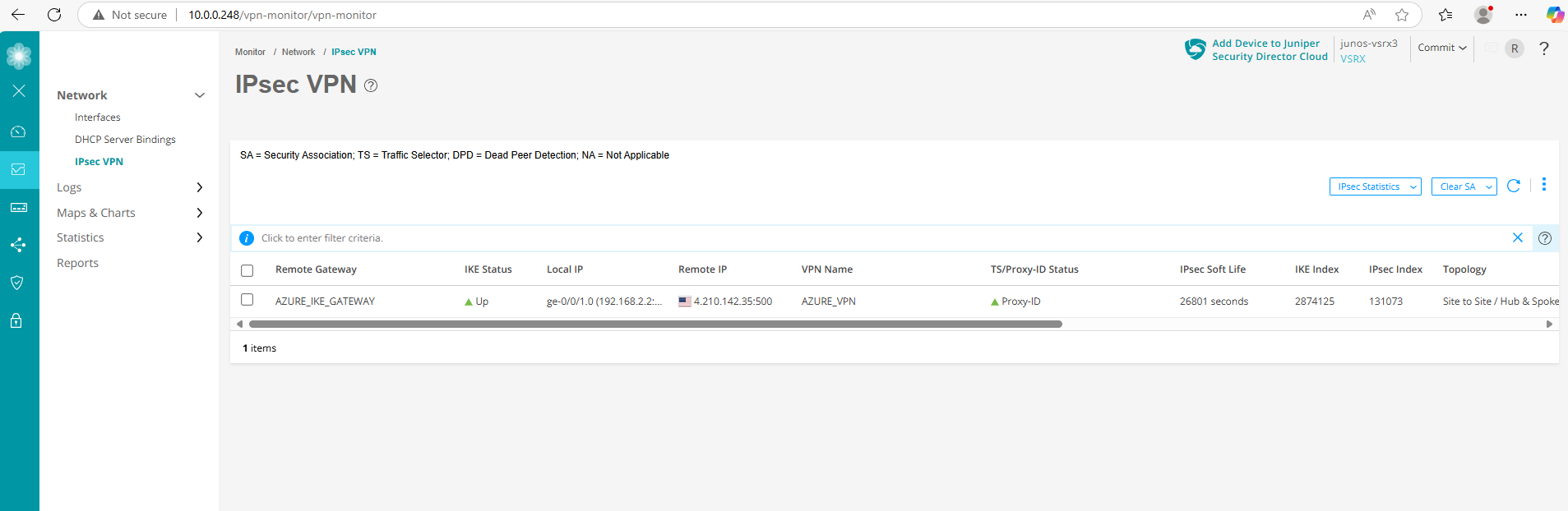
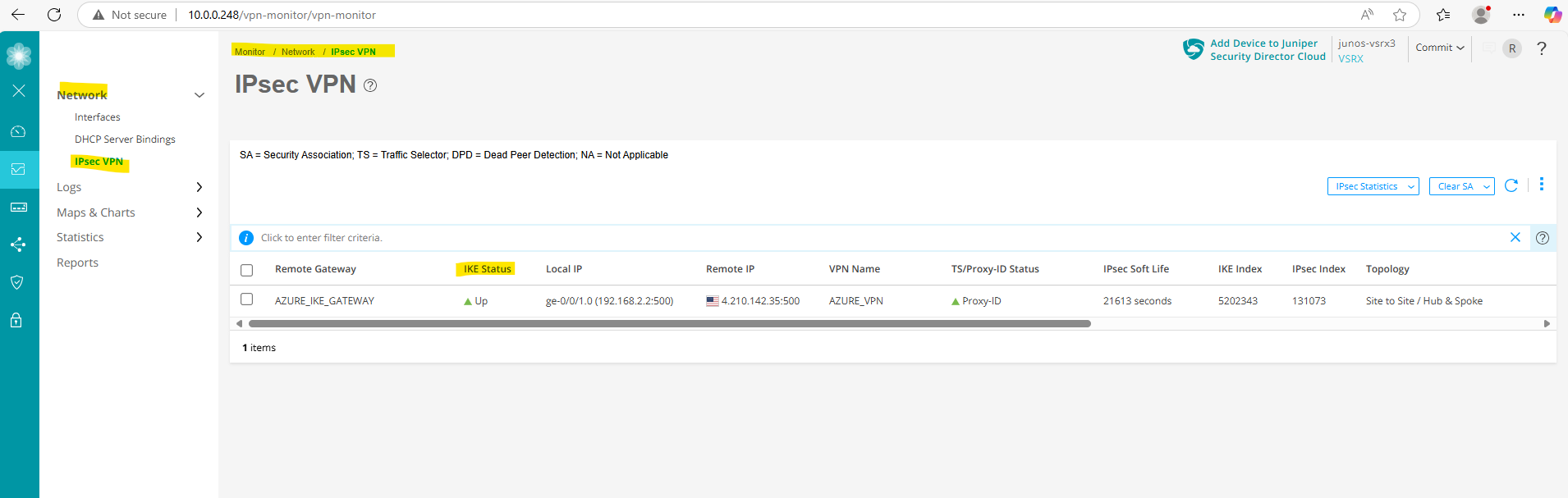
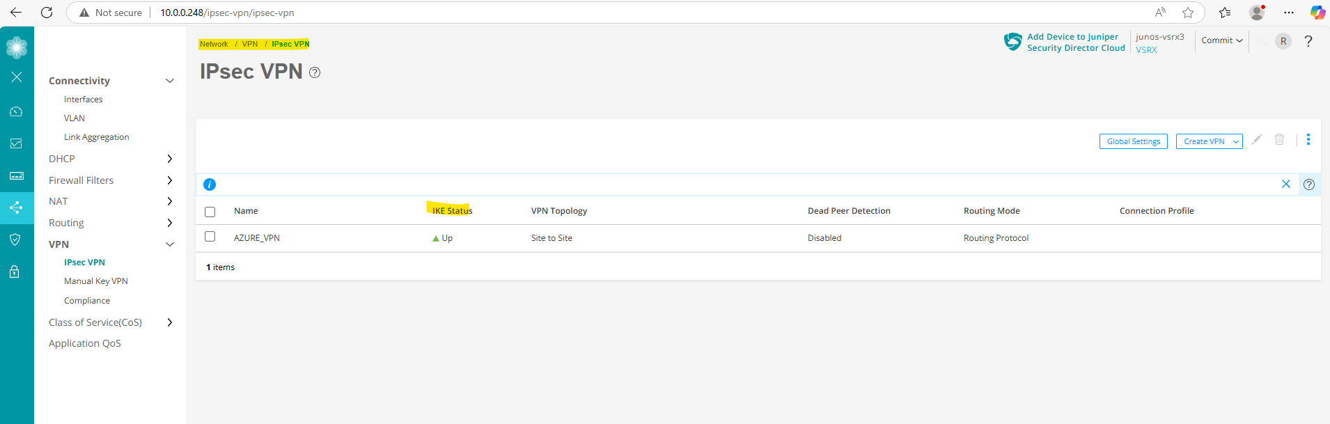
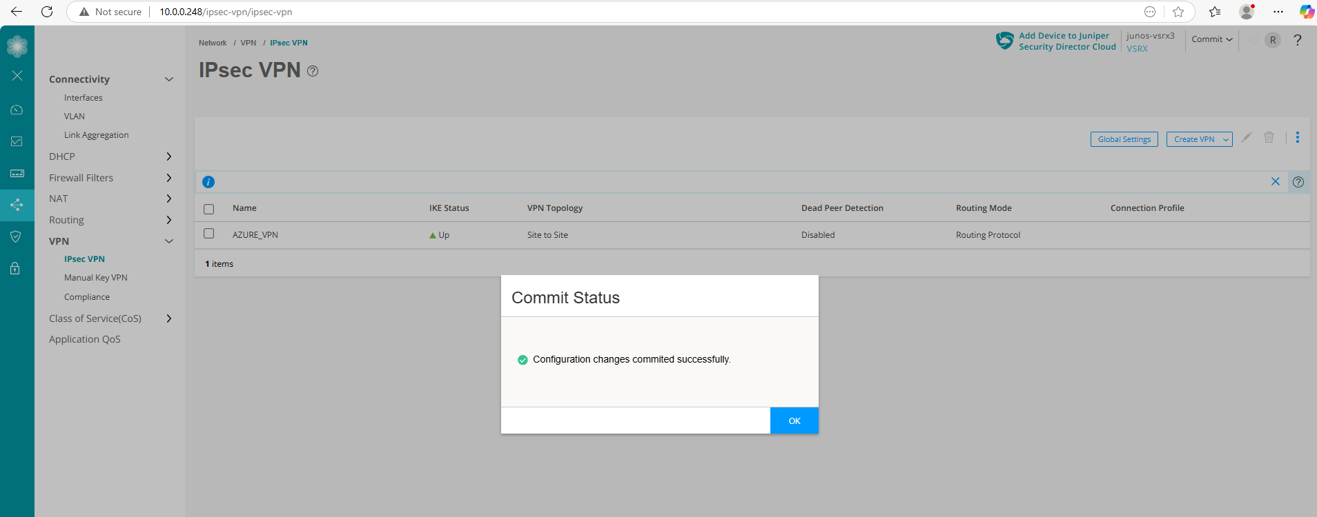
We can also check if the tunnel is up by using the Web UI under Monitor -> Network -> IPSec VPN.
Also directly on the configuration section of the tunnel under Network -> VPN -> IPSec VPN.
In Azure
Assuming you’re authenticated via the Azure CLI and have your variables defined.
PS> az login
PS> $RESOURCE_GROUP_NAME = "rsg-matrix-weu-spoke"
PS> $VPN_GATEWAY_NAME="VNet-GW"
PS> $CONNECTION_NAME = "AzureVNet-OnPremise"

az network vpn-connection show --name $CONNECTION_NAME --resource-group $RESOURCE_GROUP_NAME --output yamlc
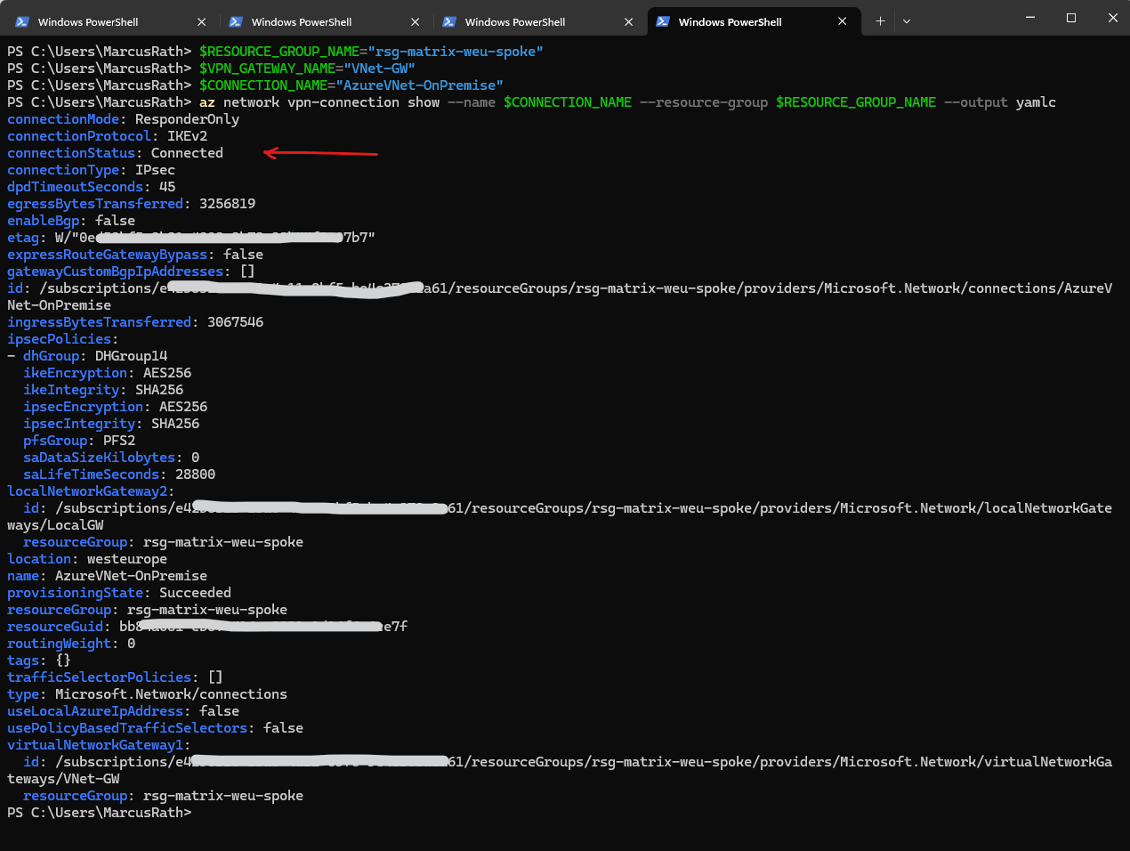
The Azure CLI supports several output formats for most commands, including az network vpn-connection show. You can specify the output format using the --output (or -o) parameter.
- json ==> Default format. Machine-readable, well-structured JSON output.
- jsonc ==> JSON with colorization (for readability in supported terminals).
- yaml ==>YAML format — more human-readable than JSON for some users.
- yamlc ==> YAML with colorization.
- table ==> ASCII table format. Very readable but not ideal for nested structures.
- tsv ==> Tab-separated values. Useful for piping or further scripting.
- none ==> No output (useful in scripts when output isn’t needed).
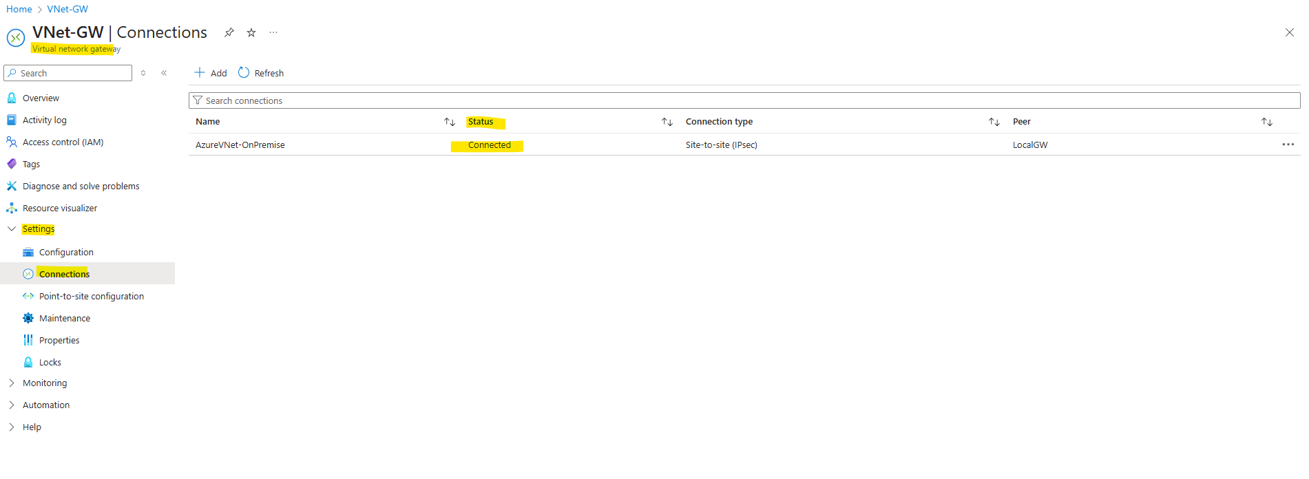
Or directly in the Azure portal either on the virtual network gateway or local gateway blade under Settings -> Connections.
Set up the Tunnel by using the Web UI
As mentioned we can set up the tunnel on Juniper also by using the Web UI like shown below.
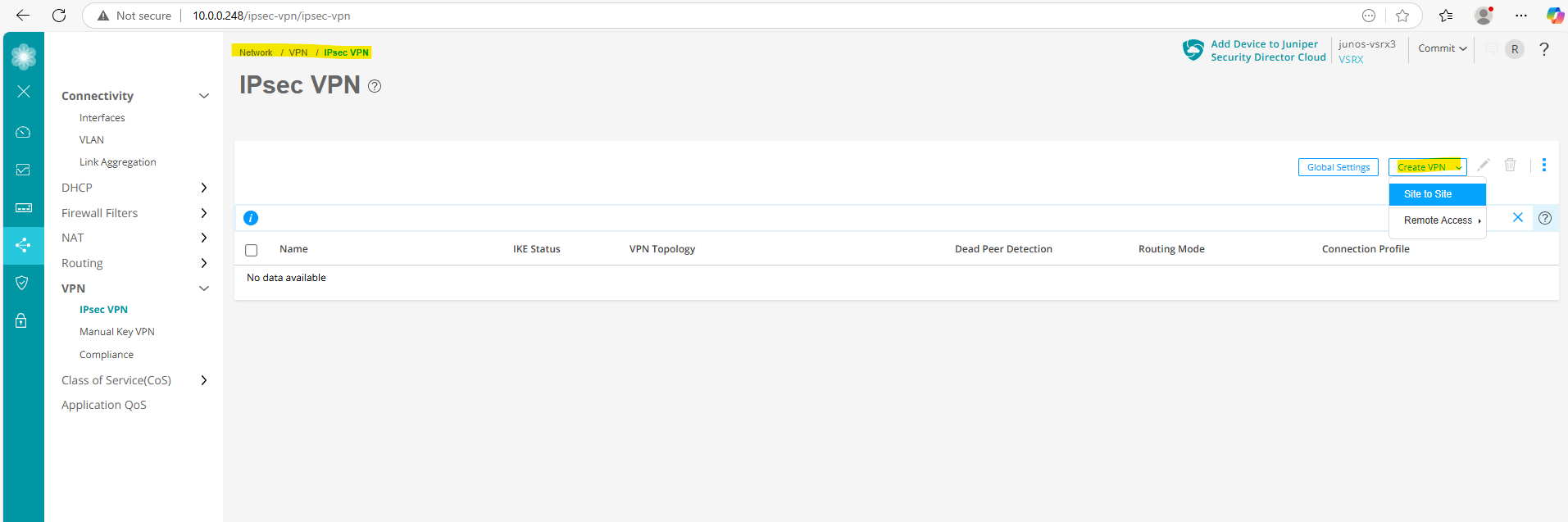
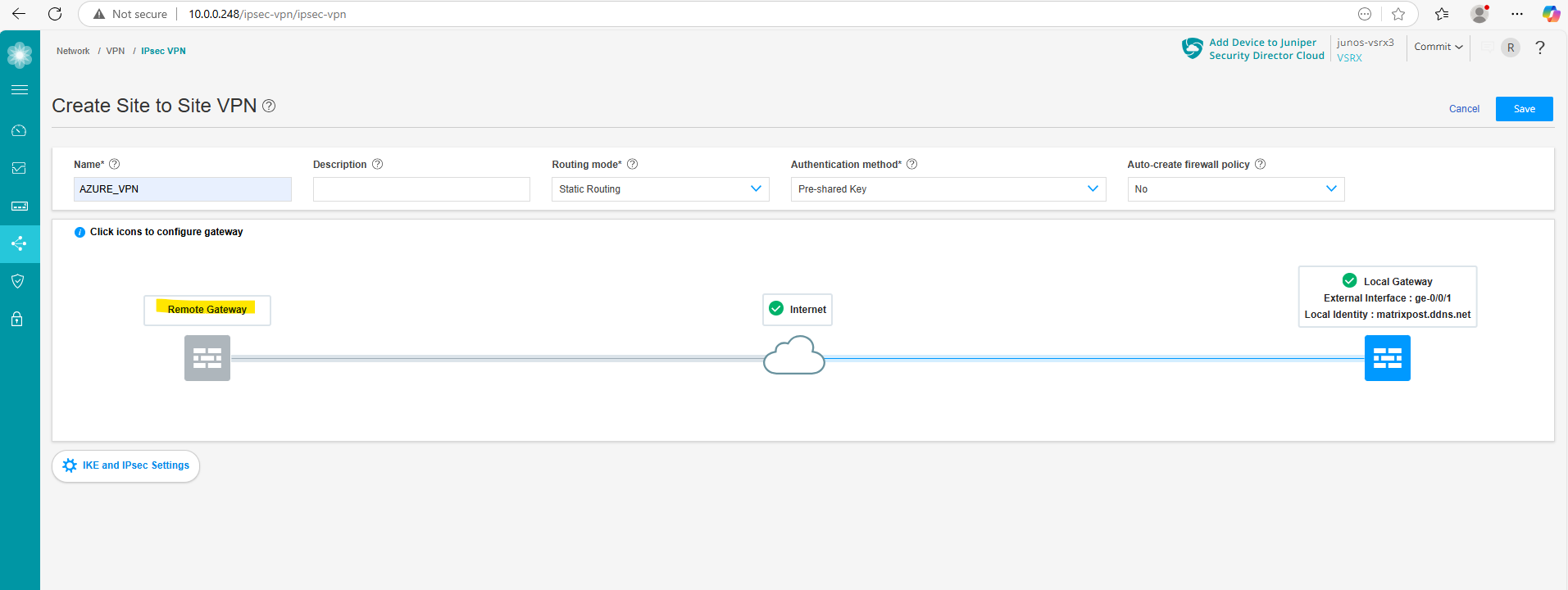
Therefore navigate to Network -> VPN -> IPsec VPN and click on Create VPN -> Site to Site like shown below.
Enter a name for the tunnel, the routing mode (Static Routing), for the authentication method we use Pre-shared Key and under Auto-create firewall policy we select No and define them later manually.
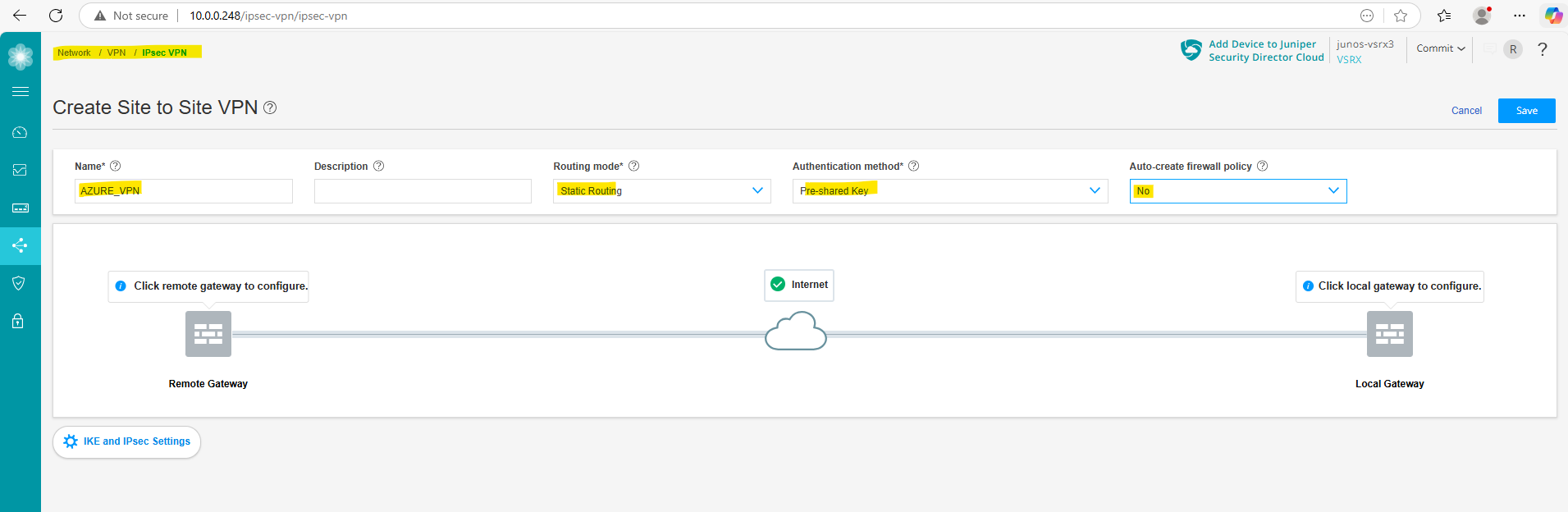
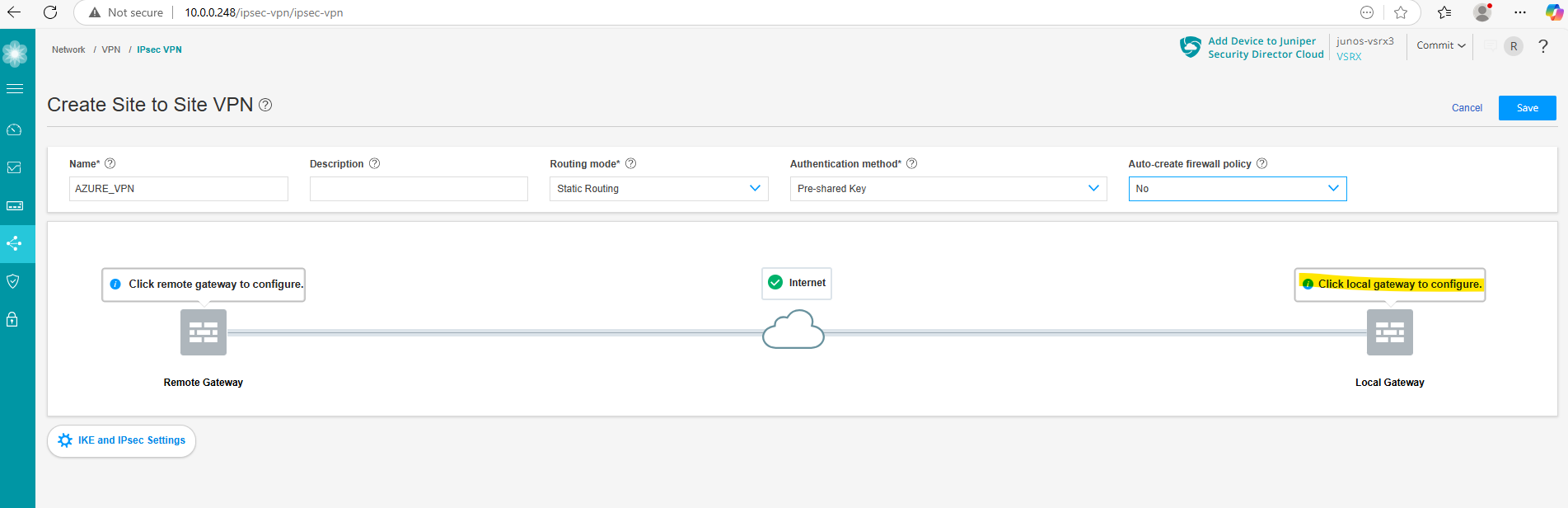
Next we configure the local gateway (Juniper) by clicking below on Click local gateway to configure.
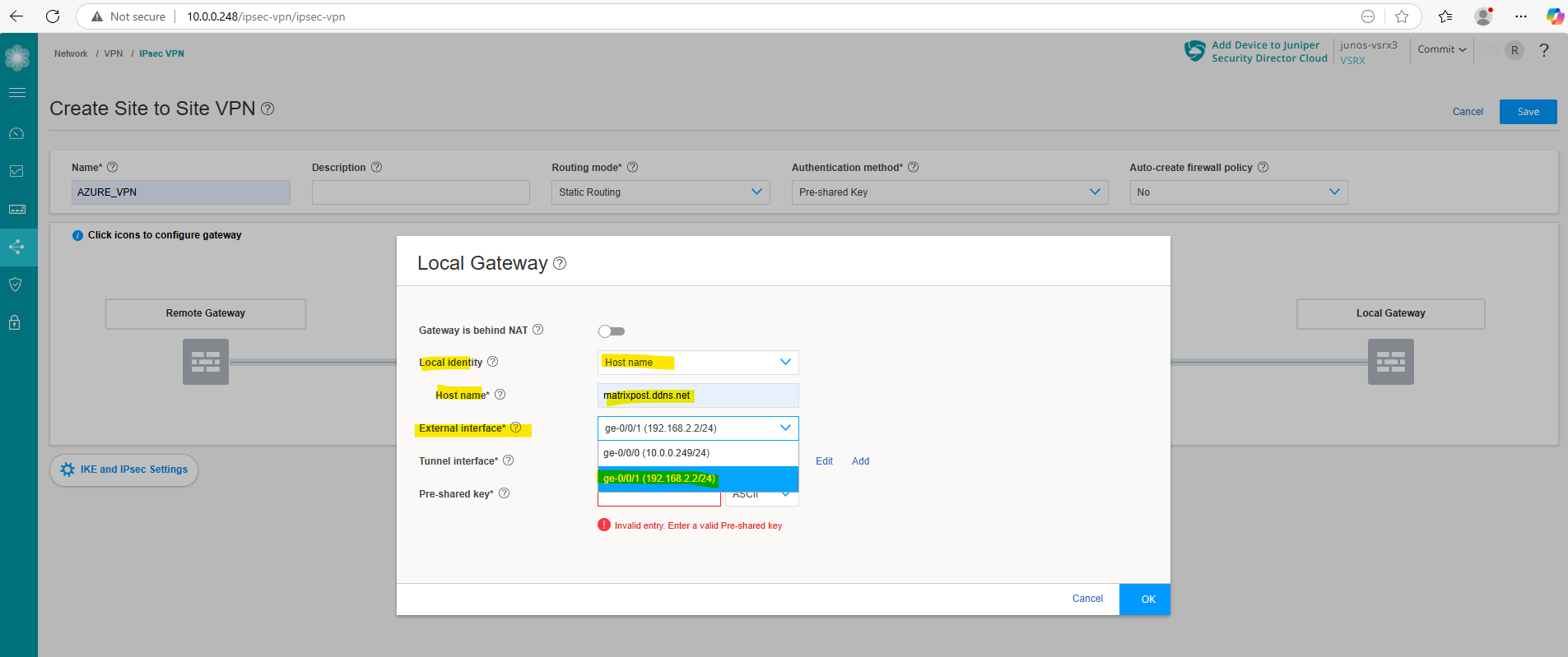
Local Gateway Object
As mentioned, click on Click local gateway to configure.
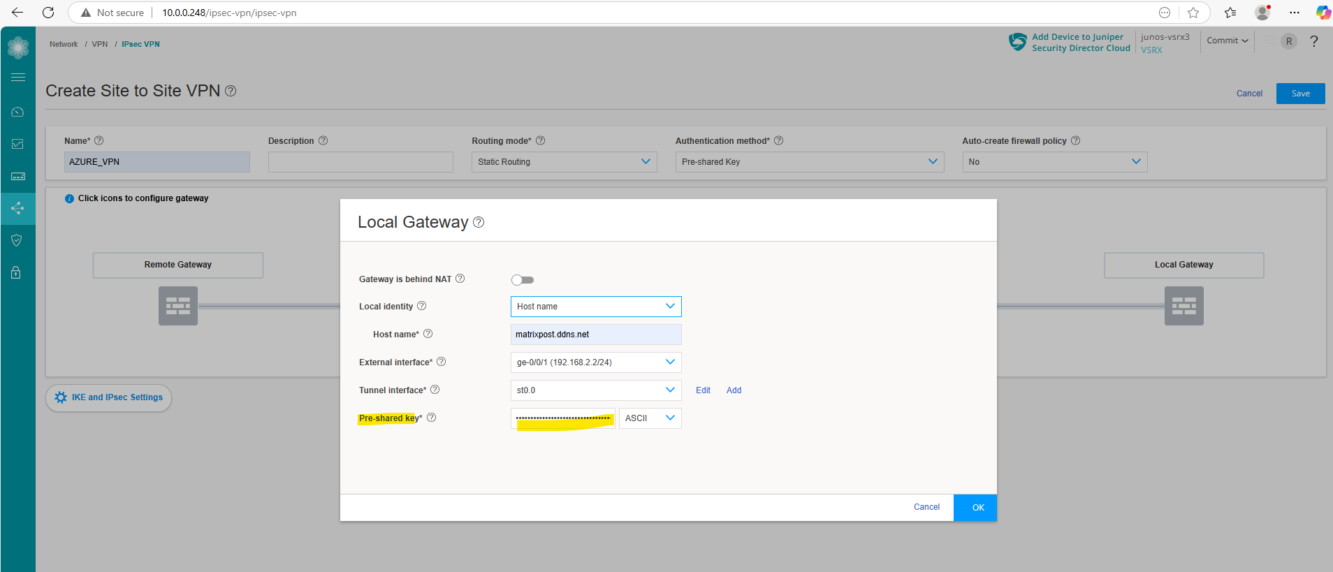
For the local identity, select Host name and enter either when using dynDNS for your public IP as in my case the FQDN or in case you will have a static public IP, just this IP.
Select the external interface and for the tunnel interface click on Add.
In my case this external interface (ge-0/0/1 192.168.2.2/24) sits behind my NAT router (FritzBox) as shown in detail regarding the architecture in my following post https://blog.matrixpost.net/azure-ipsec-vpn-tunnel-onpremise.
In my case I do not need to enable NAT-T below for the local gateway (Juniper), because Fritz!Box is already doing full NAT.
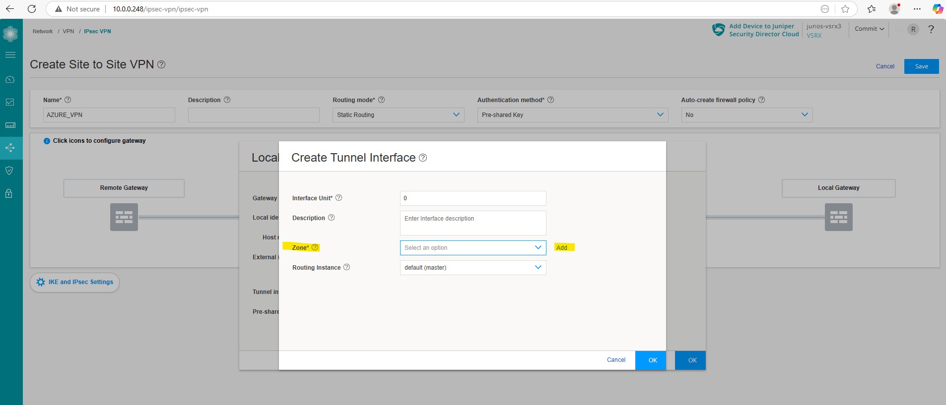
For the tunnel interface click on Add.
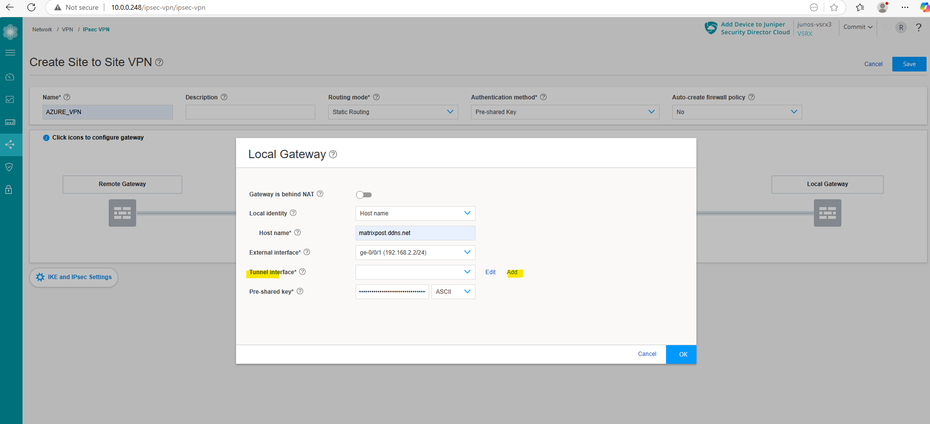
Here we need to define/create zone. We will create a new zone and name it vpn. So click on Add.
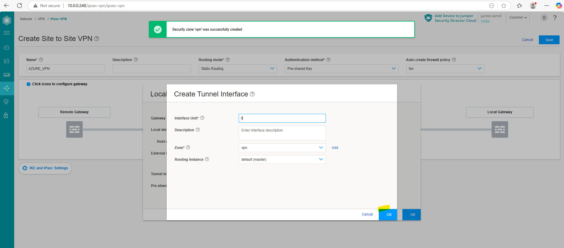
Enter a name for, I will name it vpn as mentioned and click on OK.
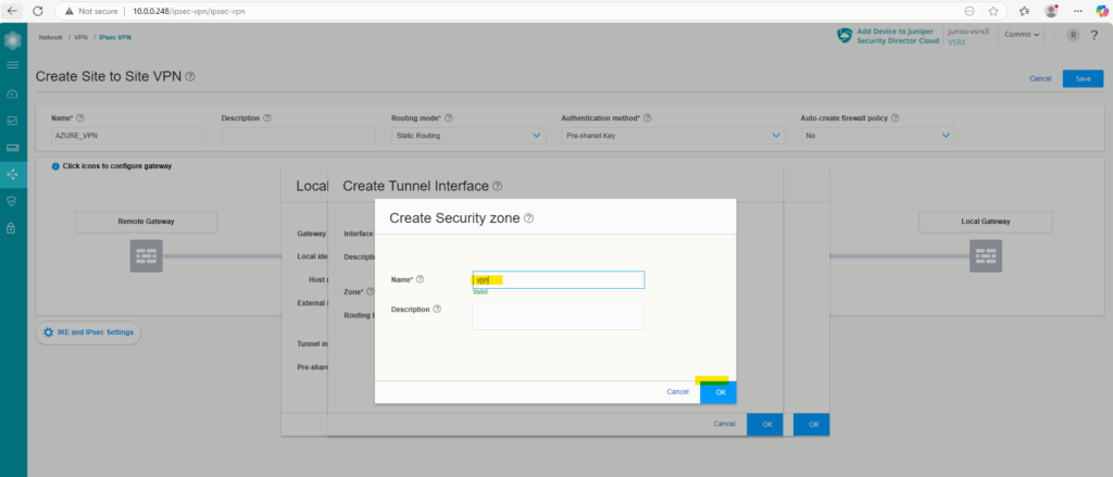
Click on OK to finally create it.
Enter the Pre-shared key for the tunnel and click on OK.
Next we will configure the remote gateway (Azure VPN Gateway).
Remote Gateway Object (Azure VPN Gatway)
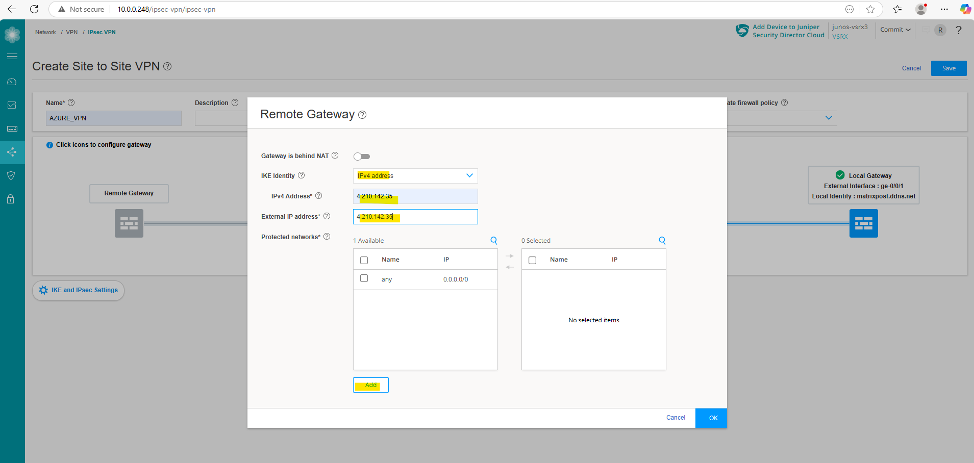
Click on Remote Gateway.
For the IKE Identity select IPv4 address, enter the public IPv4 address from your Azure gateway in both next fields with IPv4 Address and External IP address.
We also need to define and add our Azure network we want to route through the tunnel under protected networks below. Therefore click on Add.
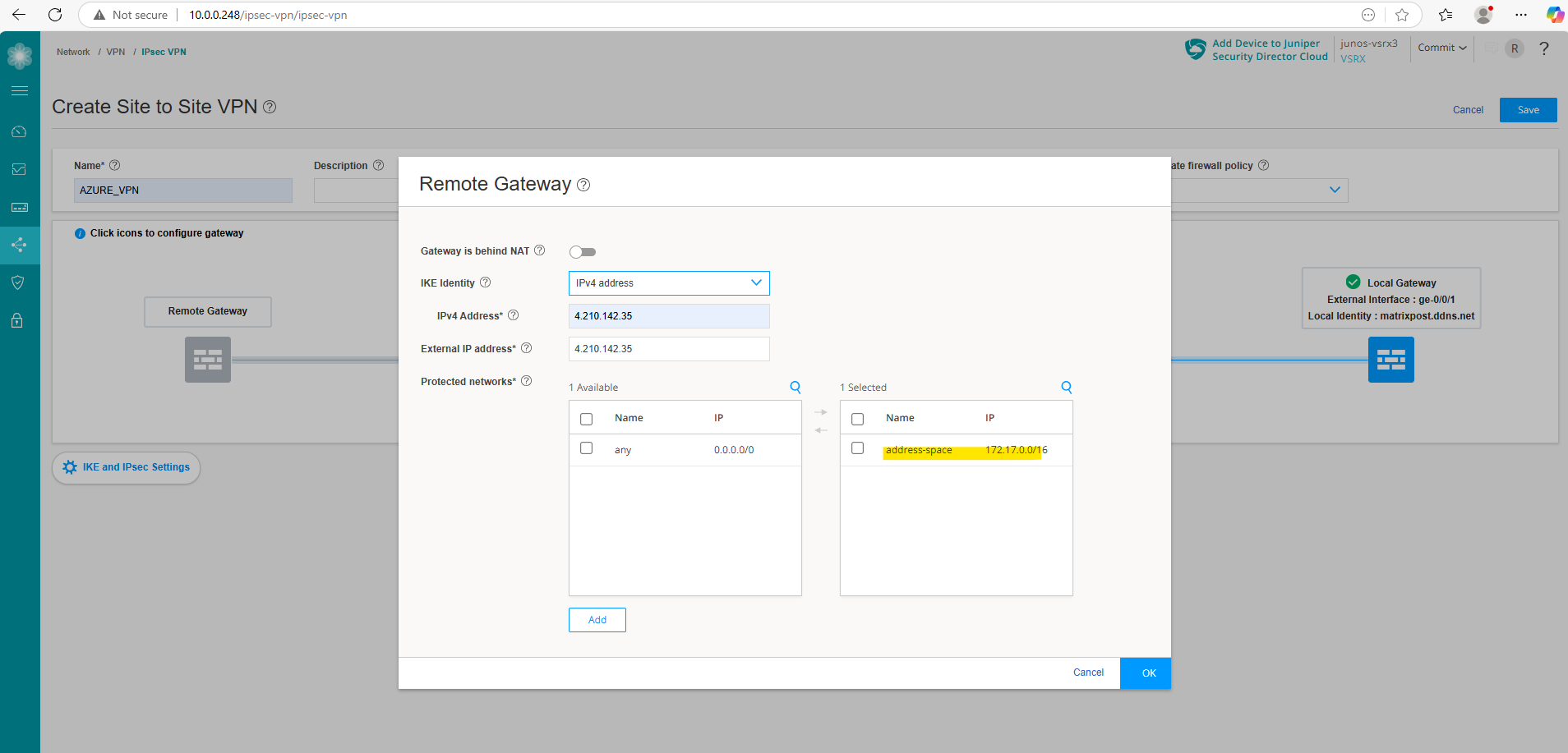
I will first add the whole address space of my virtual network in Azure.
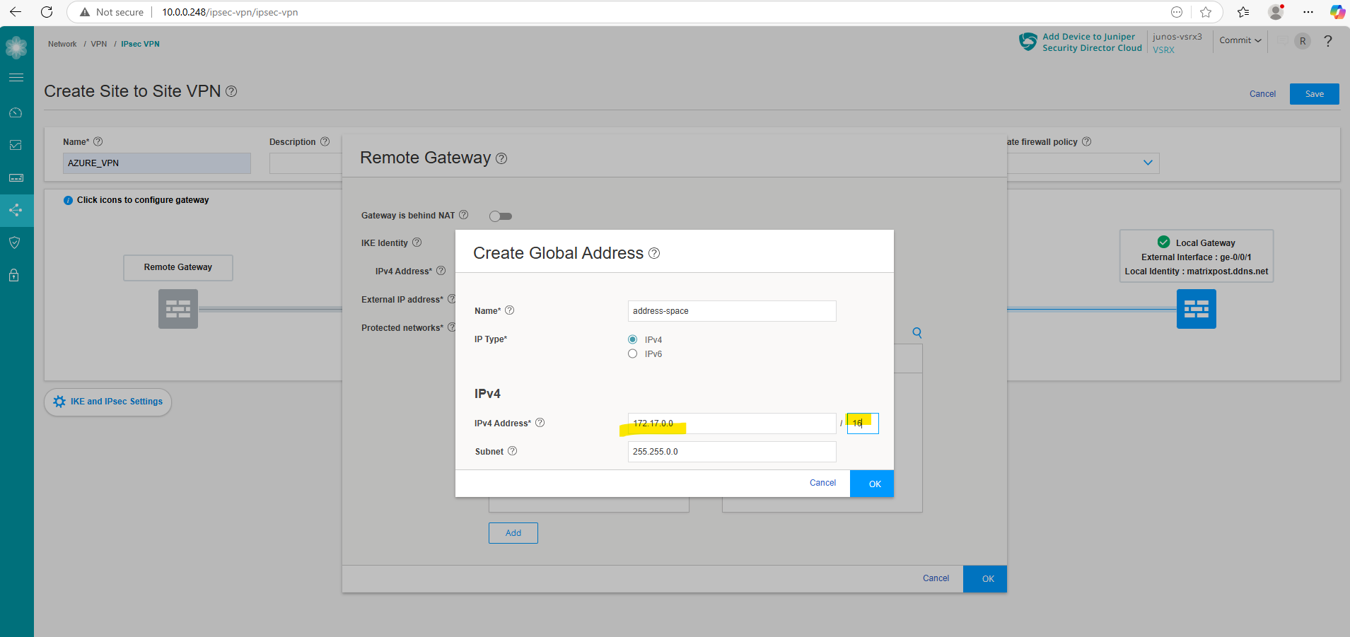
Click on OK.
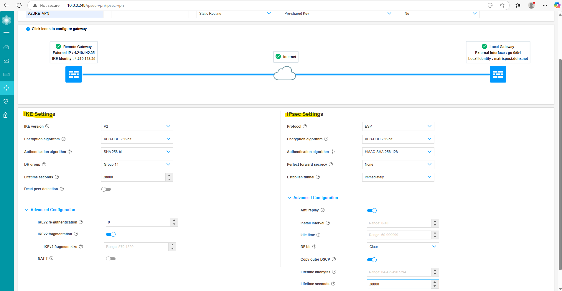
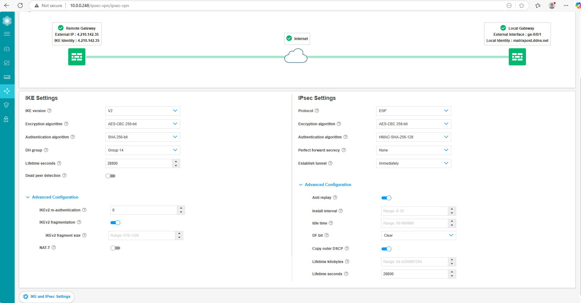
Next we need to configure the IKE and IPSec settings, so click on it below.
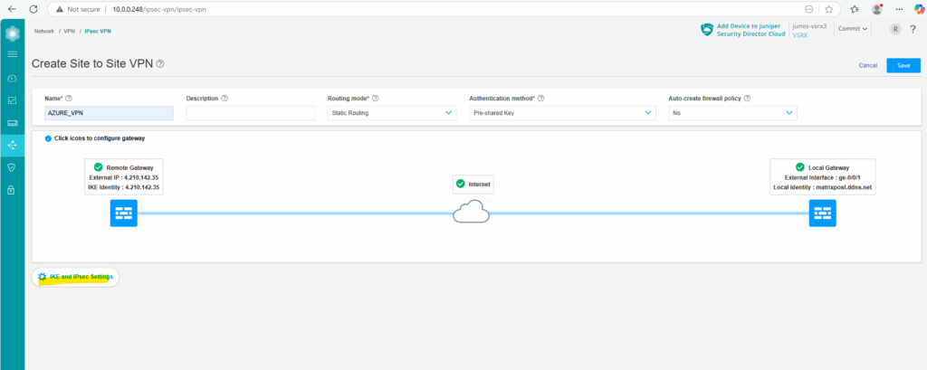
These settings finally must match with the settings in Azure.
As both platforms use different naming conventions for these settings, we need to adjust them properly. In case you are unsure about, you can use my settings here which further above is shown in the table how they match with Azure naming convention.
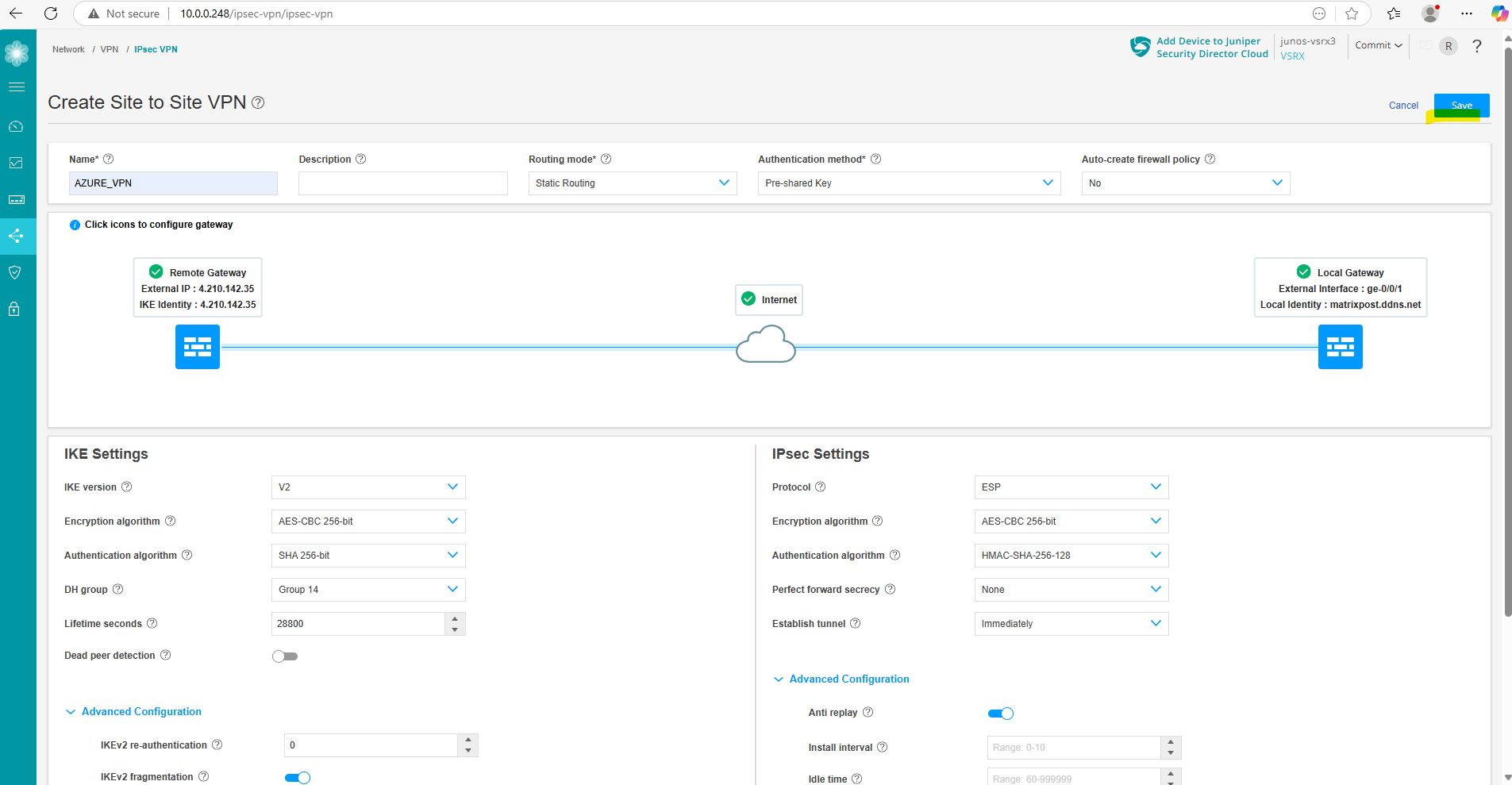
We can now save the tunnel configuration by clicking on Save on the top of the page.
And also commit the new configuration.
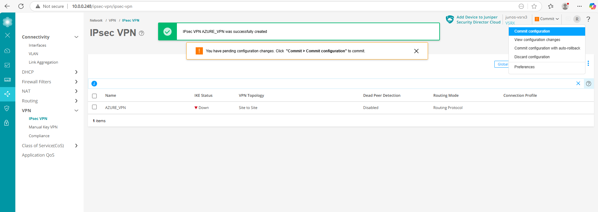
As we can see below with the green UP icon for the IKE status, our tunnel is already up.
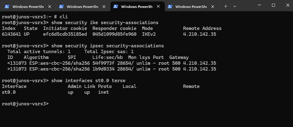
We can check this also by running the following commands in the CLI. The first will check IKE phase 1 tunnel and the second the IPSec phase 2 tunnel.
root@junos-vsrx3> show security ike security-associations
root@junos-vsrx3> show security ipsec security-associations

We can also check if the tunnel interface is up
root@junos-vsrx3> show interfaces st0.0 terse
Below we can see that our tunnel interface st0.0 is up.
Finally it looks like this.
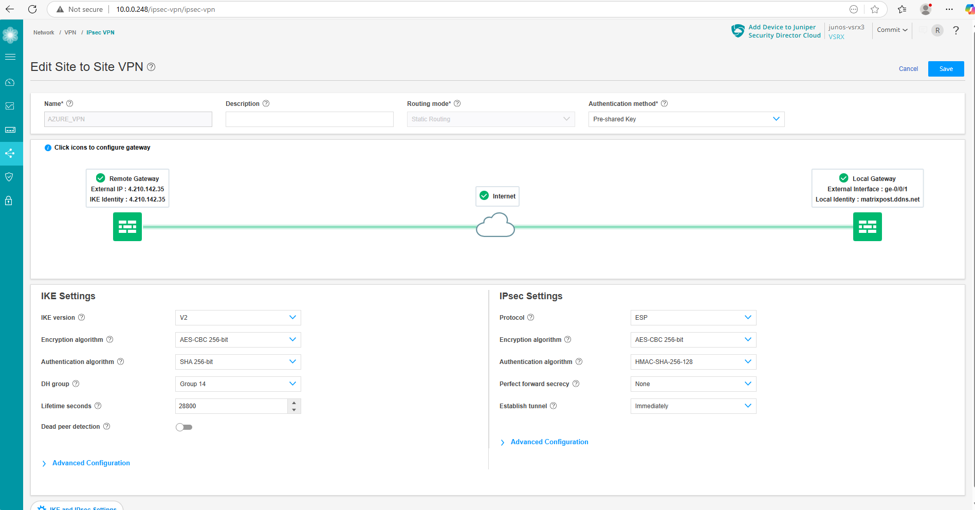
IKE and IPSec Settings section.
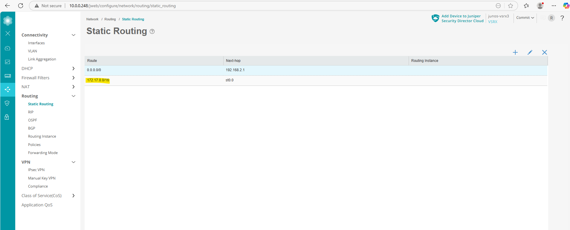
Static Routing
The static route for the Azure network is already configured and done previously further above running the following command.
# add a static routing for our Azure network is mandatory and needed
set routing-options static route 172.17.0.0/16 next-hop st0.0
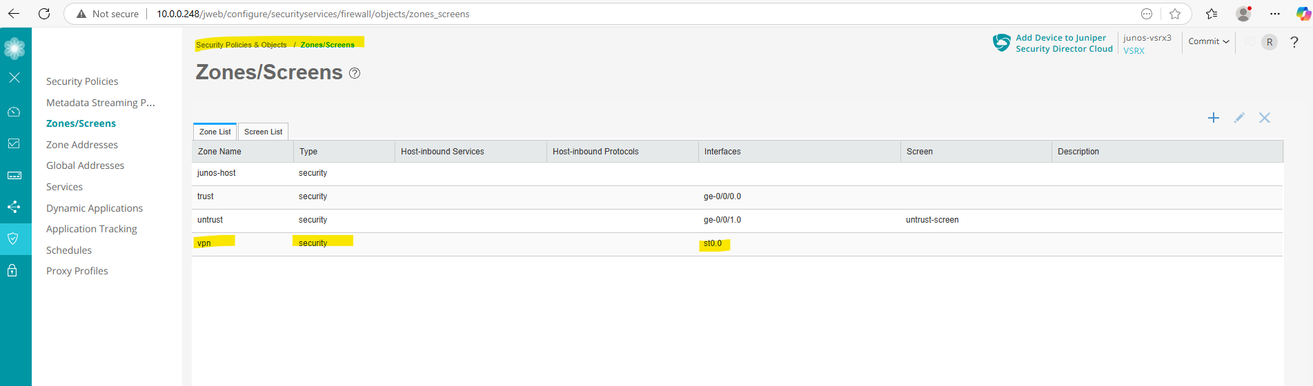
Zones (VPN)
The vpn zone we already created during the setup of the VPN tunnel further above.
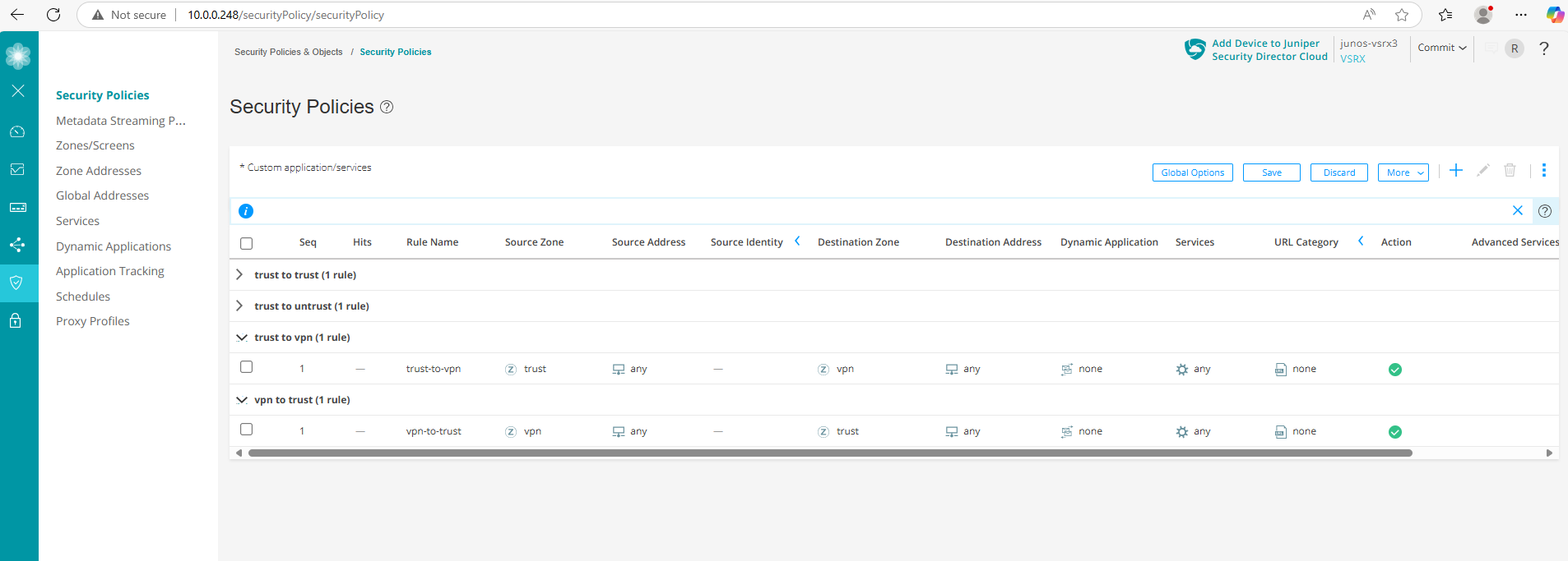
Security Policies (trust to vpn & vpn to trust)
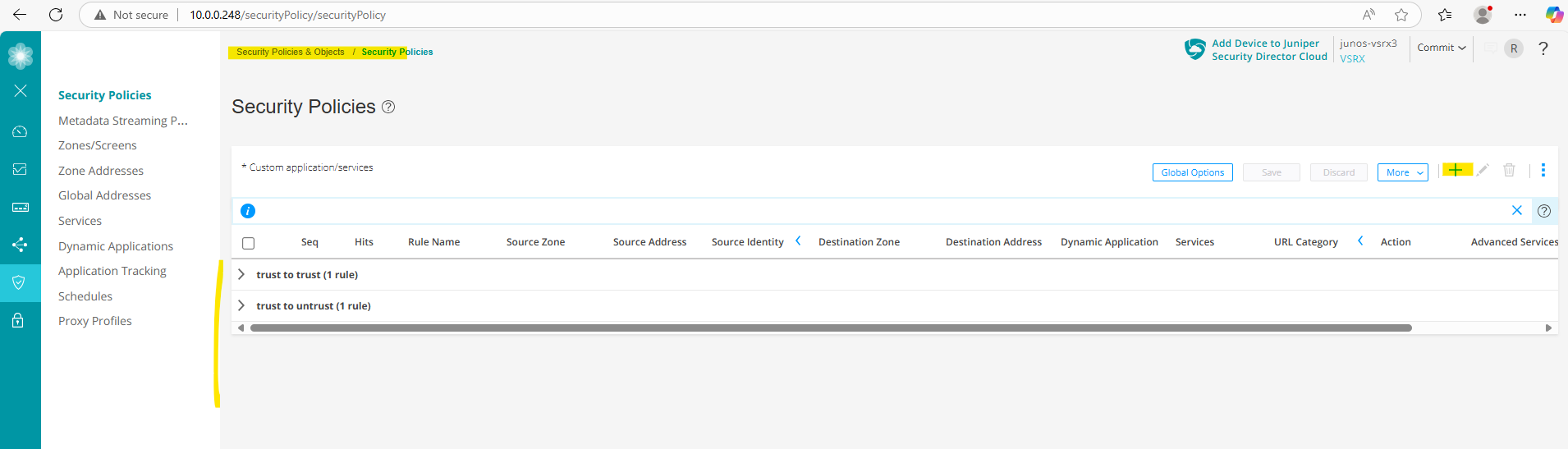
Now to finally allow traffic between on-premise and Azure, we first need to create two new security policies, one for traffic from on-premise (trust zone) to Azure (vpn zone) and one vice versa.
Under Security Policies & Objects -> Security Policies click on the plus icon to add a new one.
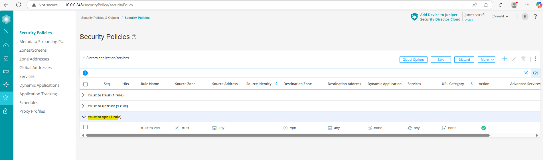
The first I will name trust-to-vpn. Here for the source we select the trust zone (our on-premise network) and for the destination zone we select our new vpn zone (Azure network). For my lab environment I will allow finally all traffic. You may want to restrict these for production.
Now we adding a further security policy and name it vpn-to-trust. Here we configure the same but vice versa to allow all traffic from Azure to on-premise.
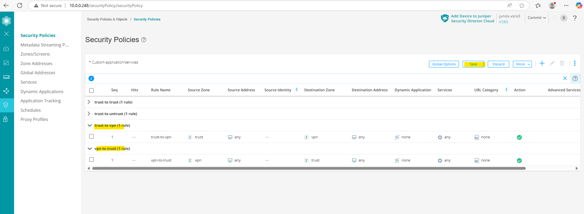
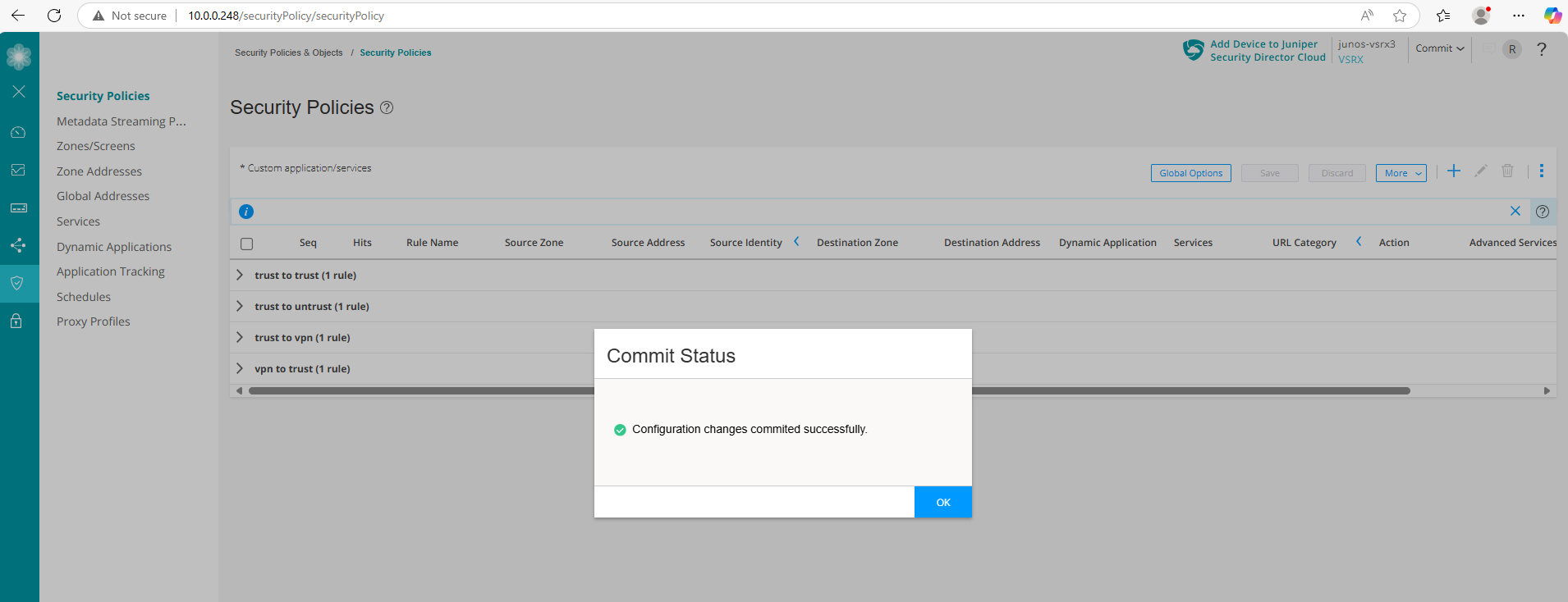
Finally save and commit the configuration.
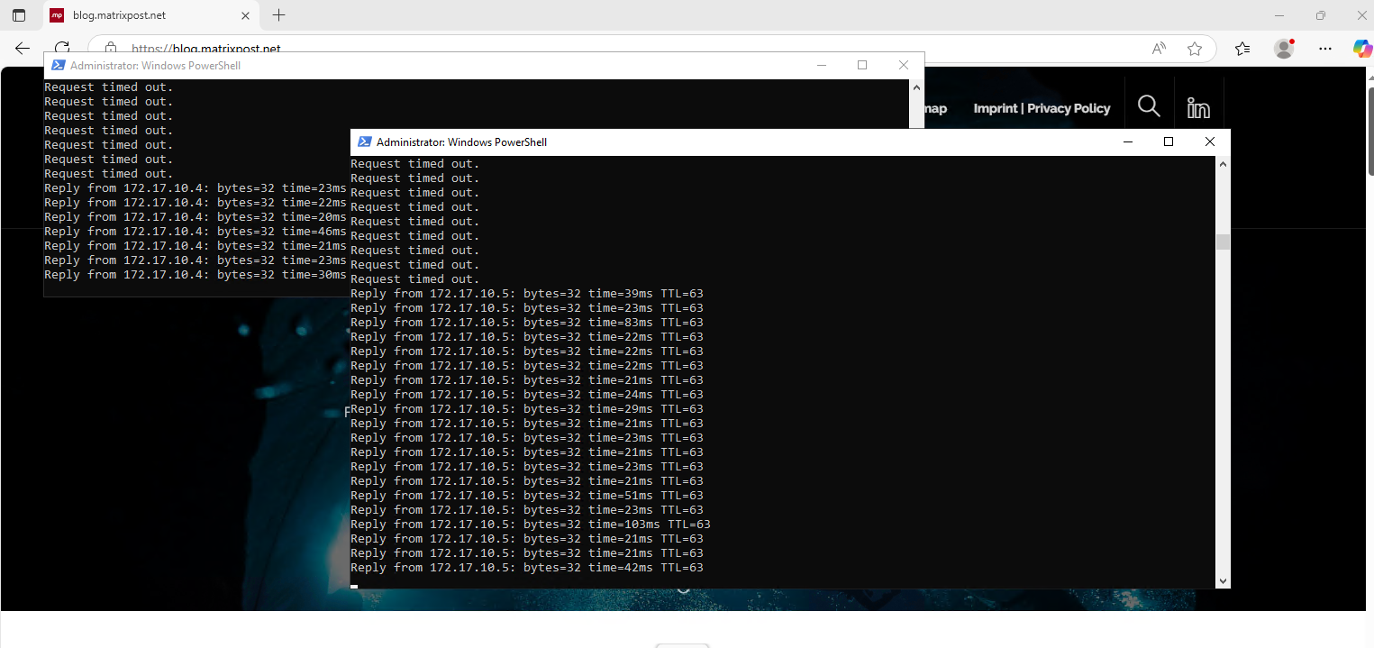
My internal hosts are immediately after committing both security policies above able to ping two running hosts in my Azure virtual network 172.17.10.0/24 as shown below.
Check if Tunnel is up
We can check if the VPN tunnel is up by running the following commands in the CLI. The first will check IKE phase 1 tunnel and the second the IPSec phase 2 tunnel.
root@junos-vsrx3> show security ike security-associations
root@junos-vsrx3> show security ipsec security-associations

We can also check if the tunnel interface is up
root@junos-vsrx3> show interfaces st0.0 terse
Below we can see that our tunnel interface st0.0 is up.
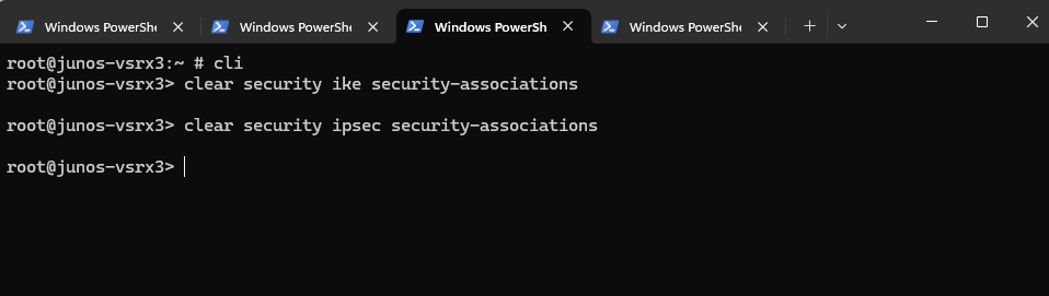
Restart the Tunnel
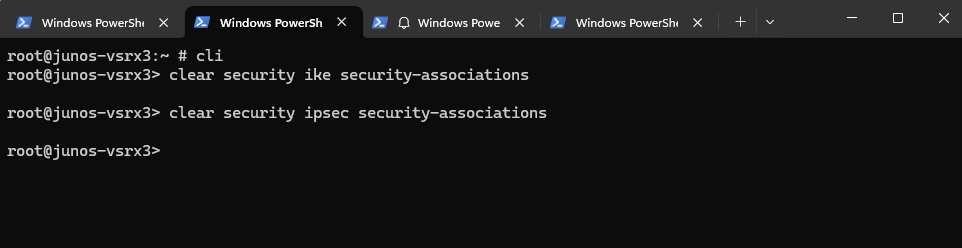
We can restart quickly the tunnel in Juniper OS by clearing the IKE phase 1 security associations and IPSec phase 2 security associations like shown below.
root@junos-vsrx3> clear security ike security-associations
root@junos-vsrx3> clear security ipsec security-associations
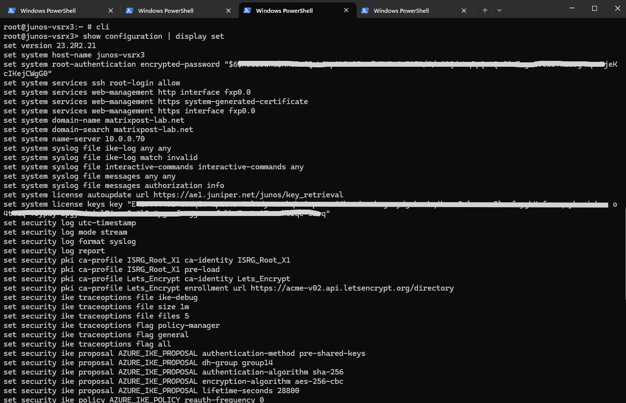
Export full Juniper vSRX3 Config (in set format)
In Juniper OS we can export/list our complete configuration by running the following command.
root@junos-vsrx3> show configuration | display set
Live Debug VPN Tunnel in Juniper
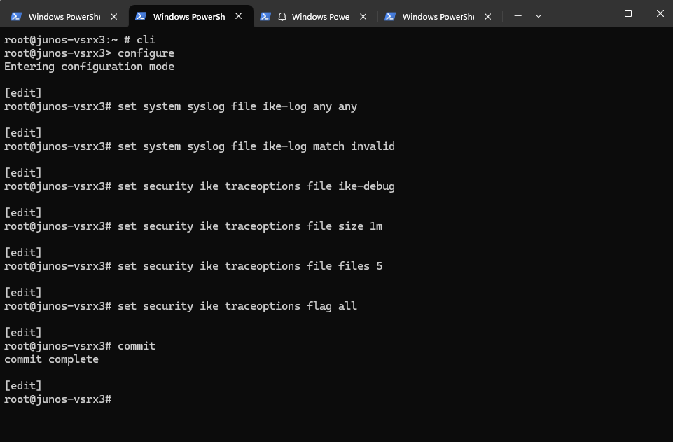
We can also debug live our VPN tunnel by using the monitor command, but first we need to enable logging and debugging if not already done by running the following commands.
set system syslog file ike-log any any
set system syslog file ike-log match invalid
set security ike traceoptions file ike-debug
set security ike traceoptions file size 1m
set security ike traceoptions file files 5
set security ike traceoptions flag all
commit
The following command starts a live debug session of the IKE negotiation process, which is crucial for troubleshooting VPN tunnel establishment issues.
root@junos-vsrx3> monitor start ike-debug
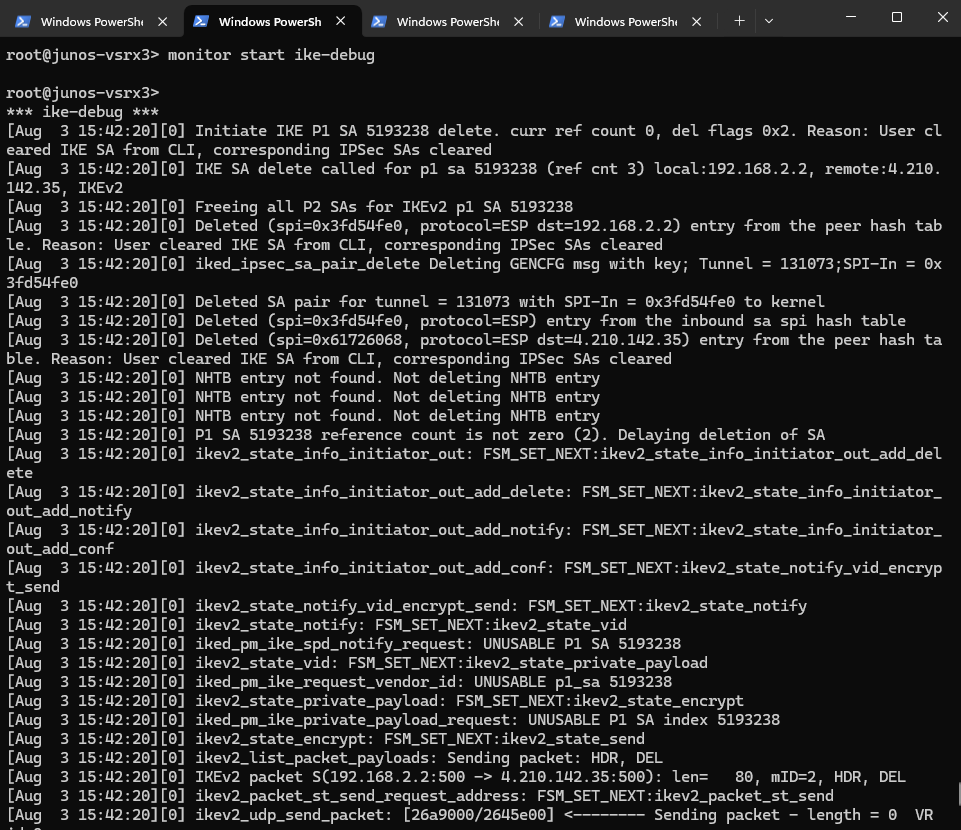
Now, while it’s running, if you want to force a reinitiation of the tunnel to see the debug output in action, restart the tunnel by executing the following commands in a second terminal window.
root@junos-vsrx3> clear security ike security-associations
root@junos-vsrx3> clear security ipsec security-associations
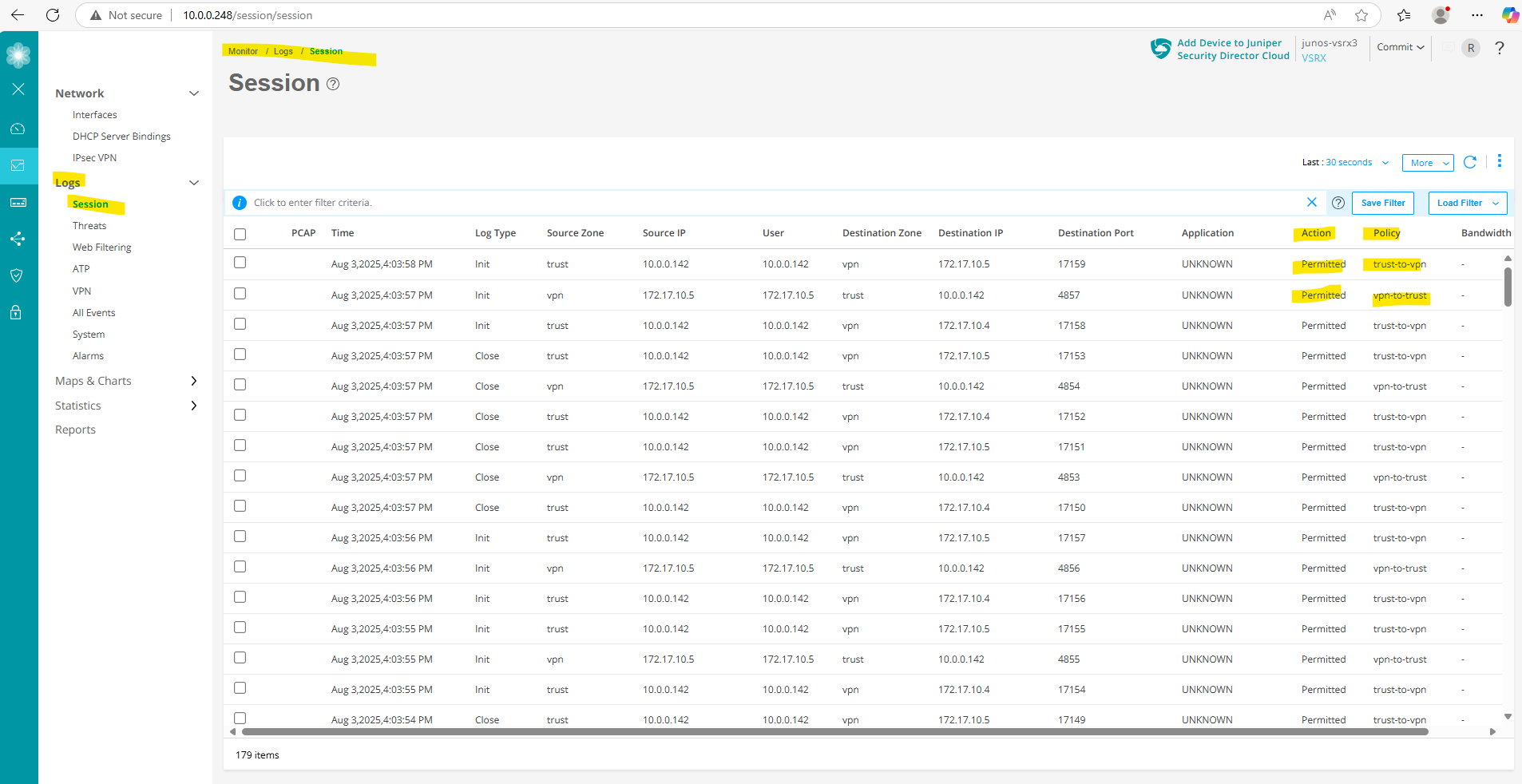
Analyze Logs by using the Web UI
When we create security policies, we can also enable logging dedicated for these rules.
We can click on the Rule Options below to enable logging for a specific security policy.
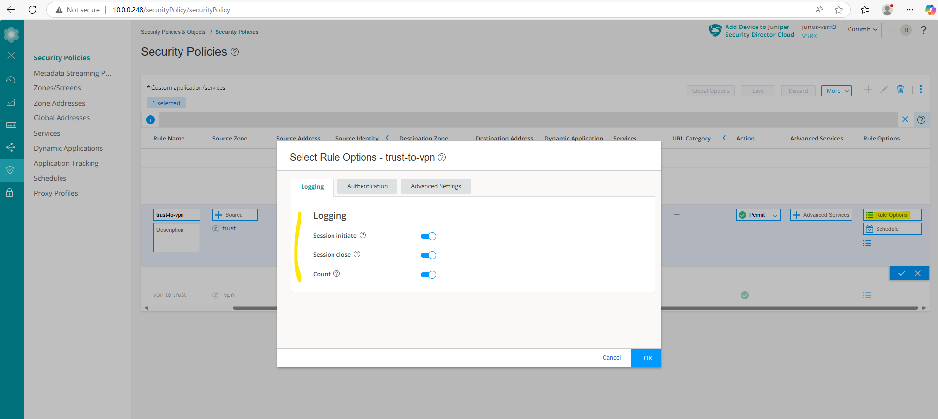
Under Monitor -> Logs -> Session we will then see any matching traffic for this rule and will see in the Action column if traffic is Permitted or not.
Links
SRX Series Firewalls
https://www.juniper.net/us/en/products/security/srx-series.htmlJuniper Licensing User Guide
https://www.juniper.net/documentation/us/en/software/license/juniper-licensing-user-guide/index.htmlvSRX Deployment Guide for VMware
https://www.juniper.net/documentation/us/en/software/vsrx/vsrx-vmware/vsrx-vmware.pdfvSRX Virtual Firewall User Guide for Private and Public Cloud Platforms
https://www.juniper.net/documentation/us/en/software/vsrx/vsrx-consolidated-user-guide/vsrx-consolidated-user-guide.pdfAdd vSRX Virtual Firewall Interfaces
https://www.juniper.net/documentation/us/en/software/vsrx/vsrx-consolidated-deployment-guide/vsrx-vmware/topics/task/security-vsrx-vmware-adding-interfaces-update.htmlUser Access and Authentication Administration Guide for Junos OS
https://www.juniper.net/documentation/us/en/software/junos/user-access/topics/topic-map/user-access-root-password.htmlJuniper vSRX Setup & Initial Configuration Guide
https://journey2theccie.wordpress.com/2021/02/04/juniper-vsrx-setup-initial-configuration-guide/Security Zones
https://www.juniper.net/documentation/us/en/software/junos/security-policies/topics/topic-map/security-zone-configuration.htmlsystem-services (Security Zones Host Inbound Traffic)
https://www.juniper.net/documentation/us/en/software/junos/cli-reference/topics/ref/statement/security-edit-system-service-zone-host-inbound-traffic.htmlExample: Configuring NAT for vSRX Virtual Firewall
https://www.juniper.net/documentation/us/en/software/vsrx/vsrx-consolidated-deployment-guide/vsrx-aws/topics/example/security-vsrx-example-aws-nat.htmlMonitor Log Messages
https://www.juniper.net/documentation/us/en/software/junos/network-mgmt/topics/topic-map/displaying-and-interpreting-system-log-message-descriptions.html