IPSec dynamic route-based S2S VPN Tunnel between two pfSense Appliances
In the last post we setup a Site-to-Site (S2S) IPSec dynamic route-based vpn tunnel between pfSense and Azure.
Today we will setup an IPSec dynamic route-based vpn tunnel between two onPremises sites with pfSense as gateway on both sites.
The Internet Key Exchange protocol (IKE, IKEv1 or IKEv2), which is used to set up a security association (SA) in the IPsec Protocol Suite, is implemented in pfSense since v. 2.2 with strongSwan (charon IKE daemon) and changed here from racoon.
- https://docs.netgate.com/pfsense/en/latest/releases/2-2-new-features-and-changes.html
- https://www.strongswan.org/
- http://www.racoon2.wide.ad.jp/w/
- https://en.wikipedia.org/wiki/StrongSwan
- https://en.wikipedia.org/wiki/Internet_Key_Exchange
- https://en.wikipedia.org/wiki/IPsec
Routed IPsec (VTI)
https://docs.netgate.com/pfsense/en/latest/vpn/ipsec/routed-vti.html
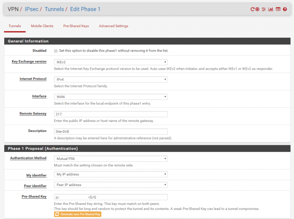
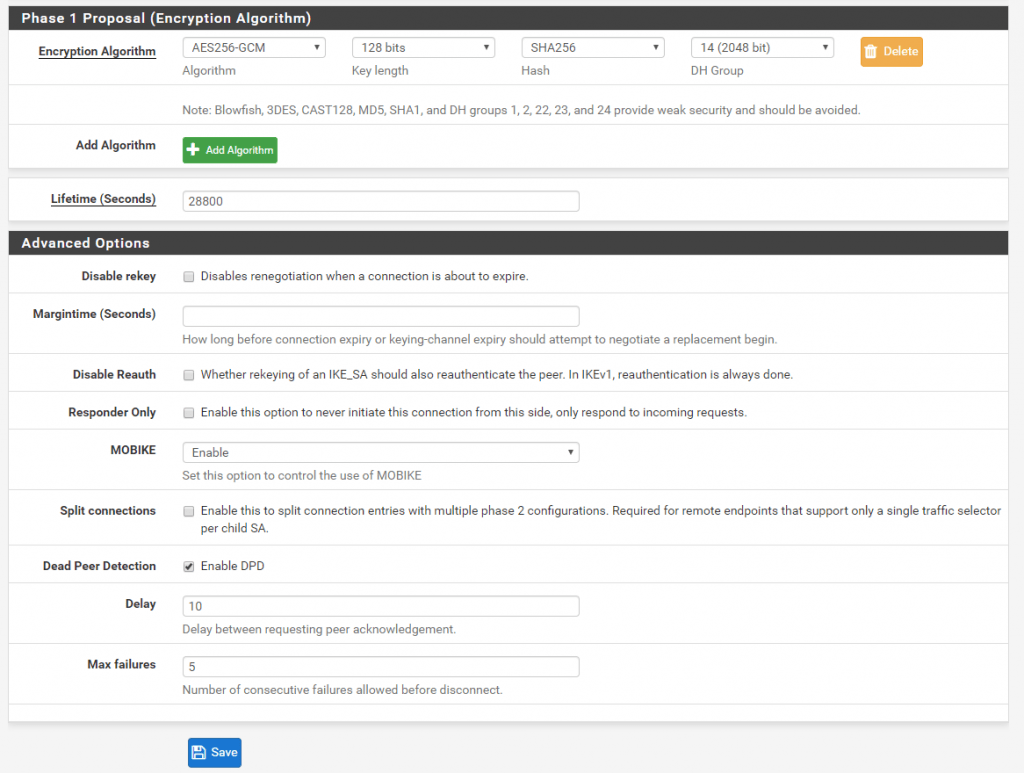
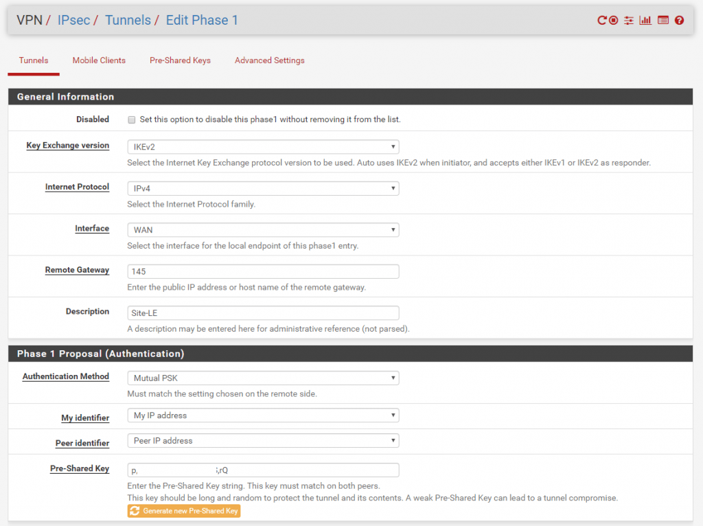
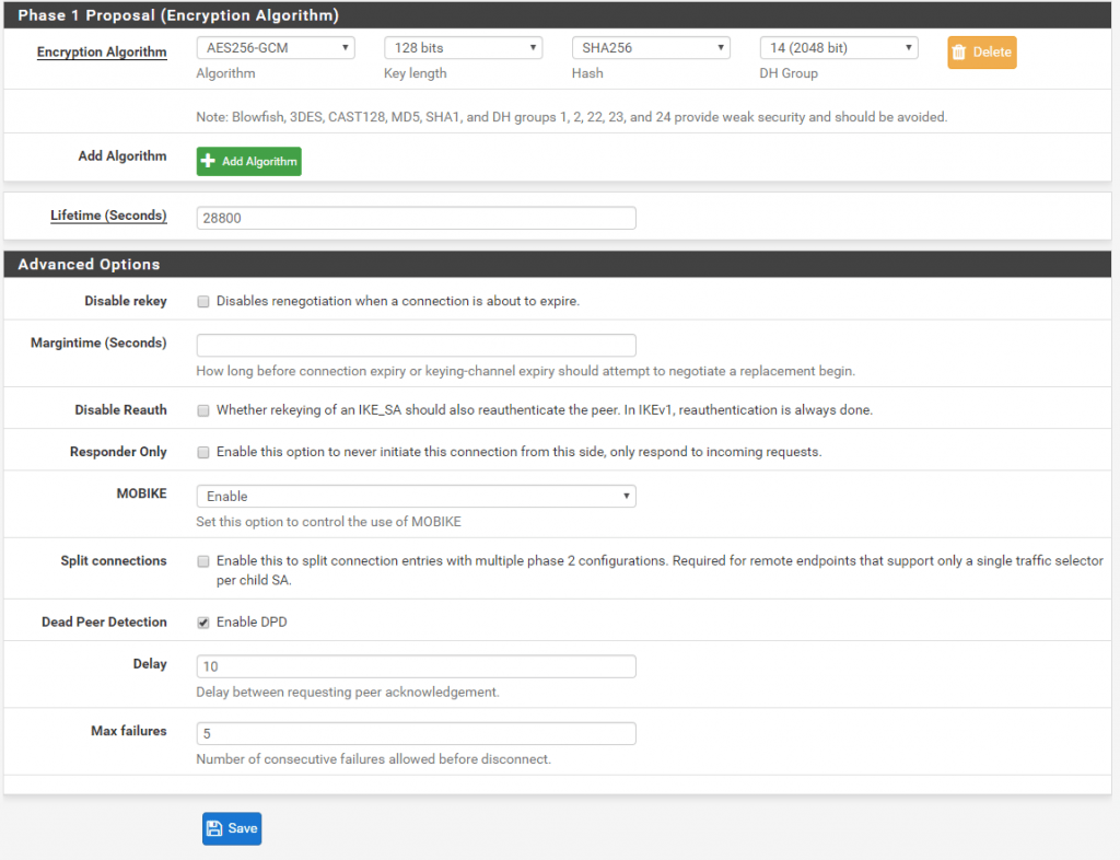
First we must configure on each site the IPSec Phase 1.
Site A
Site B
Now after we finished configure the Phase 1 on each site we add an IPSec Phase 2 on each site.
Site A
As we create a route-based S2S vpn tunnel and dynamic routing with BGP, we use for the Mode here Routed (VTI).
VTI stands for Virtual Tunnel Interface.
When you select this mode the Local Network is switched automatically to Network. In this mode we must create a transit network with a subnet mask of /30 which can contain only two IP addresses, one for each site. Through this transit network we later route our local subnets and the BGP session to advertise routes.
So the first benefit from a route-based S2S VPN over a policy-based S2S VPN, is that we do not have to create for each subnet, we want to route through the tunnel, a dedicated IPSec Phase 2 tunnel (aka Proxy IDs/Traffic Selectors), we just need to create one phase 2 tunnel (our transit network) on each site, through which all other subnets finally will be routed.
For the transit network select a /30 subnet which doesn’t conflict with your other local subnets on each site. In my case I use the 172.19.0.0/30 subnet.
Site A have the IP 172.19.0.1 and Site B have the IP 172.19.0.2 for the transit network.
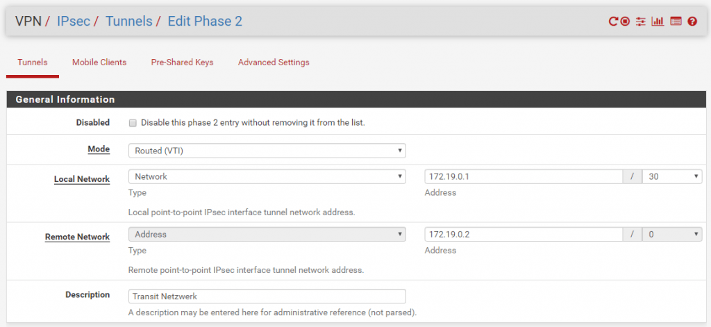
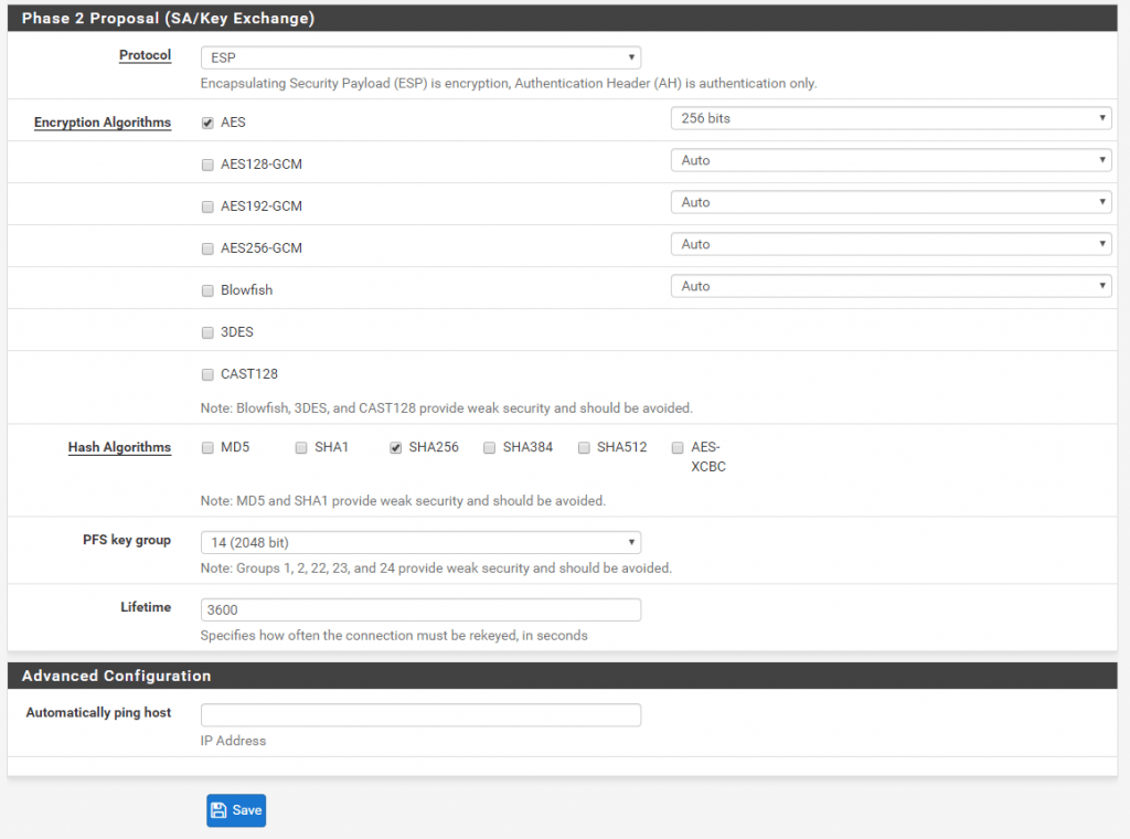
Site B
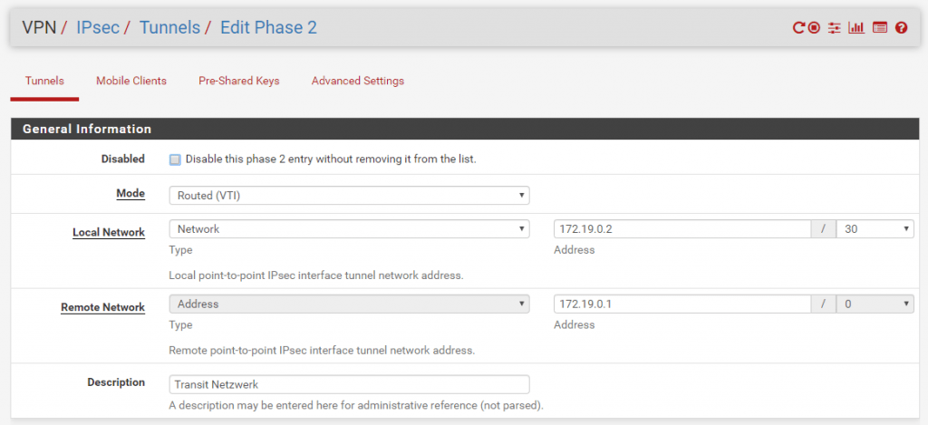
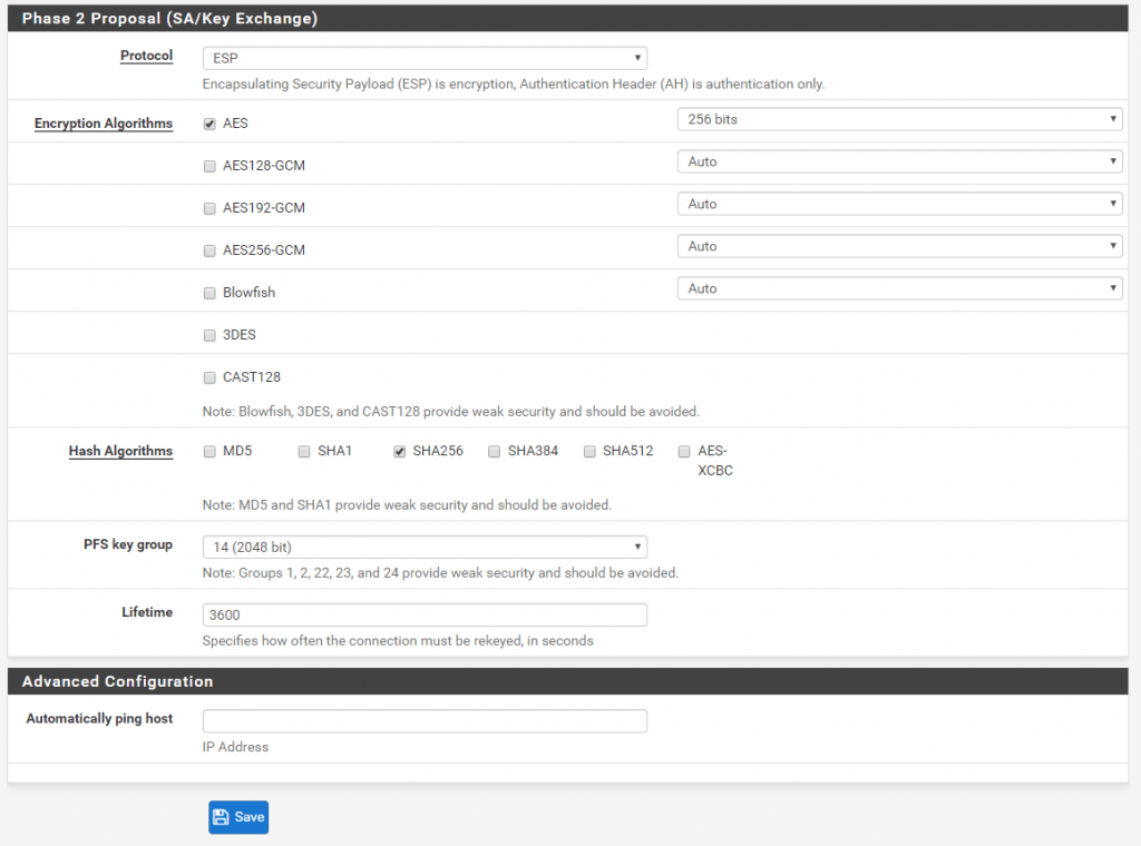
Because we set the Mode to Routed (VTI) in Phase 2 of the IPSec tunnel, pfSense created a virtual tunnel interface (VTI).
All traffic which has to be routed through the tunnel will send through this interface, finally to the peer’s VTI interface and assigned IP address (aka BGP peer IP address), both VTIs on each site will build here a virtual point-to-point link.
But first we have to assign and enable the interface on pfSense at each site!
So click on the Add button and save to assign it under Interfaces -> Assignement
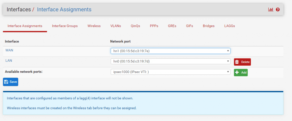
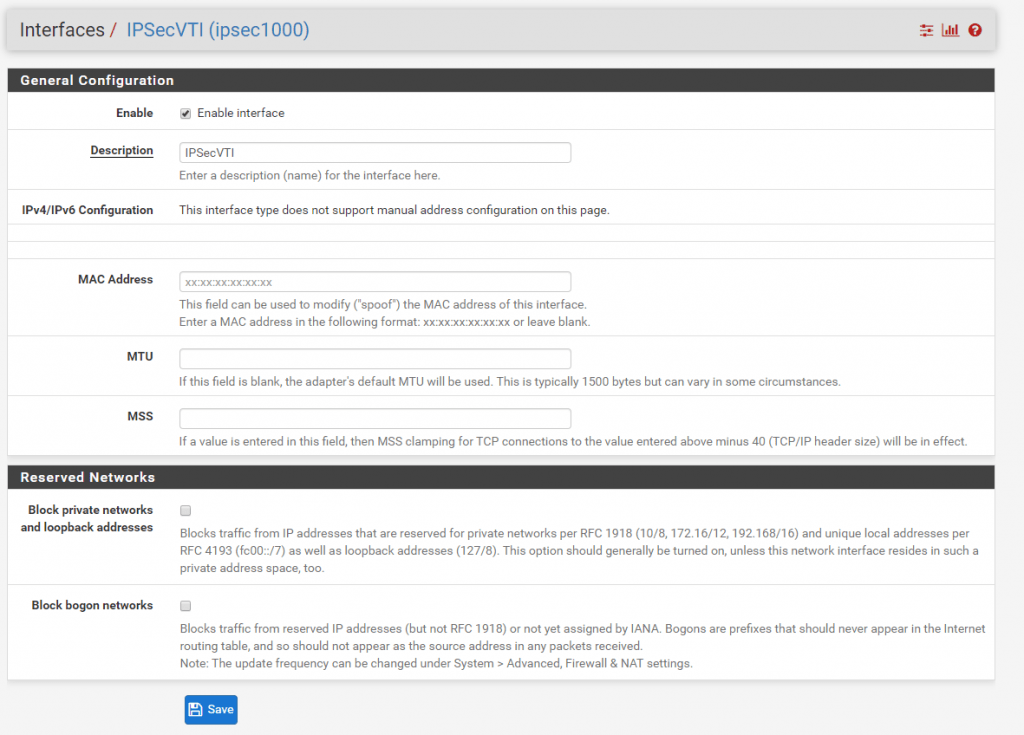
In my case I rename the default name of the interface from Opt1 to IPSecVTI for a better understanding.
And don’t forget to enable the Interface!
Further note that you cannot configure the IPv4 or IPv6 addresses. This interface automatically gets his IP from the previous configured transit network on Phase 2.
You can see the assigned IPSecVTI interface and its IP address on the dashboard of pfSense. Here from Site A.

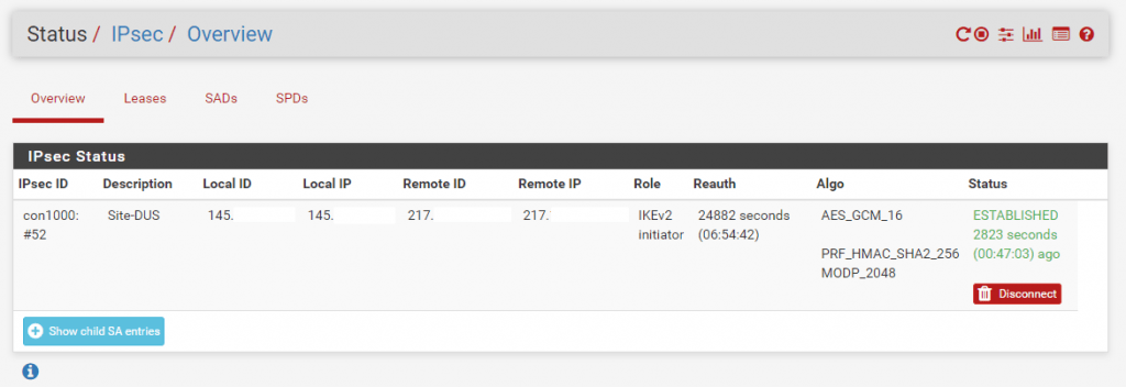
To see if the tunnel is up and running go to Status – IPSec in the menu. As you can see the connection between both peers is established.
But before traffic will be routed over the tunnel we first must configure the BGP Protocol on both sites at pfSense. At the moment both pfSense don’t know how to route traffic destined for the other site because they haven’t any routing information for the remote site.
BGP is advertising the routing informations between the connected peers. So with BGP we do not need to configure manual static routes for the remote site and peer, as they will automatically advertised from them with BGP.
OpenBGPD is since pfSense version 2.4.5 depricated and since version 2.5.0 no longer available in pfSense!
Therefore you should move to FRR. How to install and configure FRR you will find in my following post.
The BGP Protocol is implemented with the OpenBGPD daemon in pfSense. You can install this package with the Package Manger. Go to System – Package Manger and search for the OpenBGPD package and click on install.
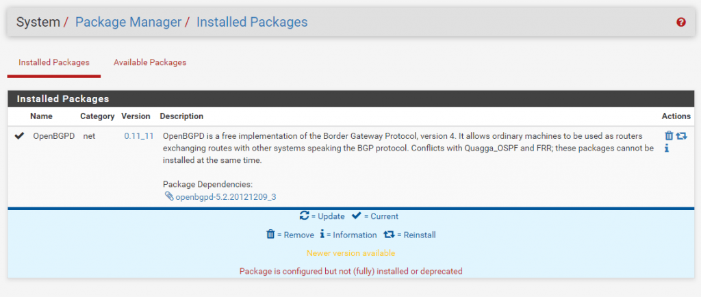
After the package is installed you will get a new entry in the Services menu with OpenBGPD.
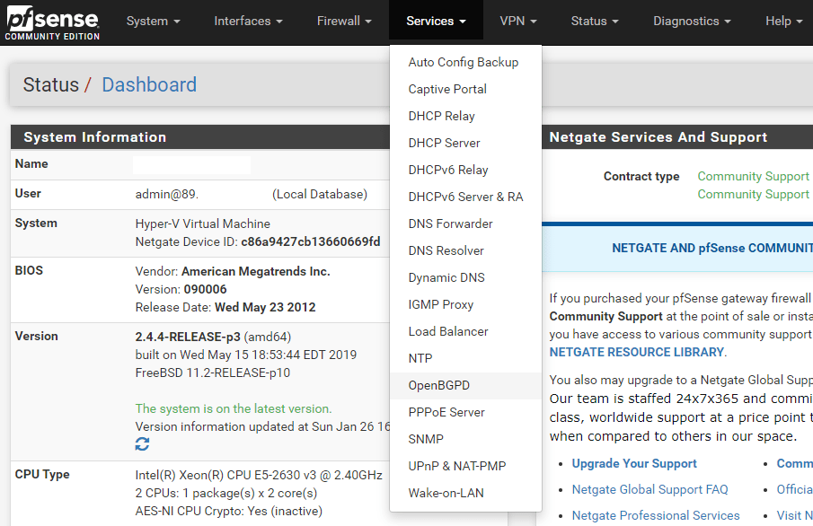
Here you must configure the BGP Protocol for each site.
Site A
First we must choose a private AS Number for each site. You will find private AS Numbers at the following link
https://en.wikipedia.org/wiki/Autonomous_system_(Internet)
(64512 – 65534 Reserved for private use RFC1930, RFC6996)
For Site A I choose 65501. As Router IP you must enter the internal IP from the LAN interface and the Listen on IP you can leave blank as it listens on all IPs in this case. At Networks you specify which local networks should announced to the remote site over the BGP Protocol. If you want to announce all local subnets from Site A to Site B then add here inet connected for the directly attached networks at pfSense and inet static for all static routes defined at pfSense and Site A in this case.
Be aware of adding the inet connected to the advertised networks, both networks from the local adapters (WAN/LAN) will be advertised as route to the other peer.
In this case, also the complete WAN Subnet in which the adapter resides, will be advertised as route to the other peer/site.
Because of this and depending on the route configuration of the remote site clients, the clients could be try to reach all public IPs from this WAN Subnet through the vpn tunnel instead the default gateway for the internet traffic, which is not desirable and successful.
In my case this doesn’t matter, as the clients use a different gateway for the internet traffic.
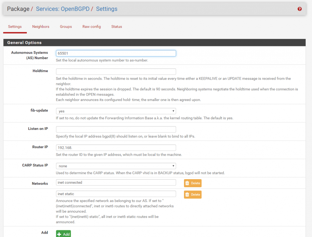
Before we configure the Neighbor we must create a Group which represents the remote site B and it’s AS Number.
For Site B I choose the AS Number 65502. The Name you can define as wanted.

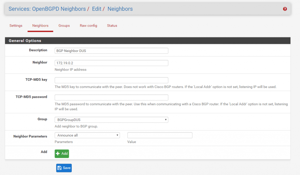
Now we can configure the BGP Neighbor which is Site B. At Neighbor put in the IP address from the transit network and Site B in my case 172.19.02. Then you must select the previous created Group in my case BGPGroupDUS.
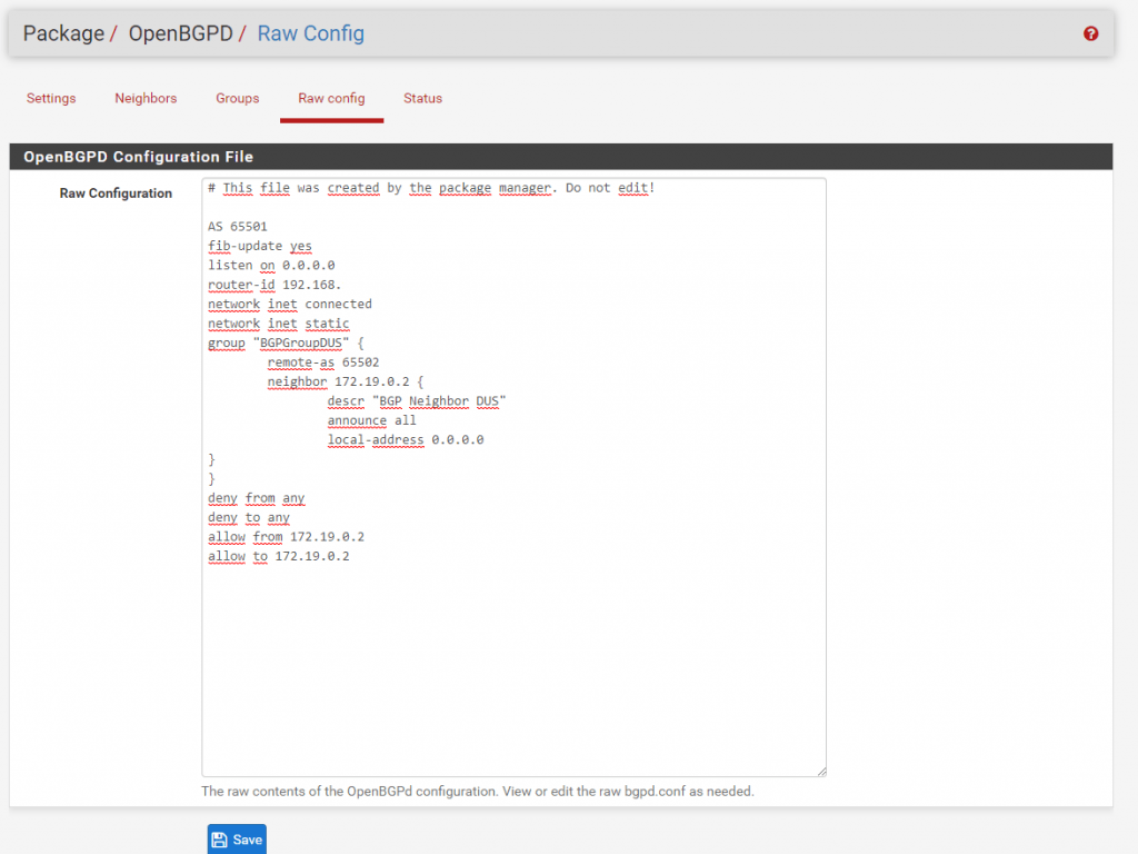
You can see the complete configuration from BGP at Raw config.
Under Status you can see if BGP works and the routes are announced correctly to the remote site. But before it can work we first have to configure the same settings adapted to Site B which are the following screenshots:
Site B
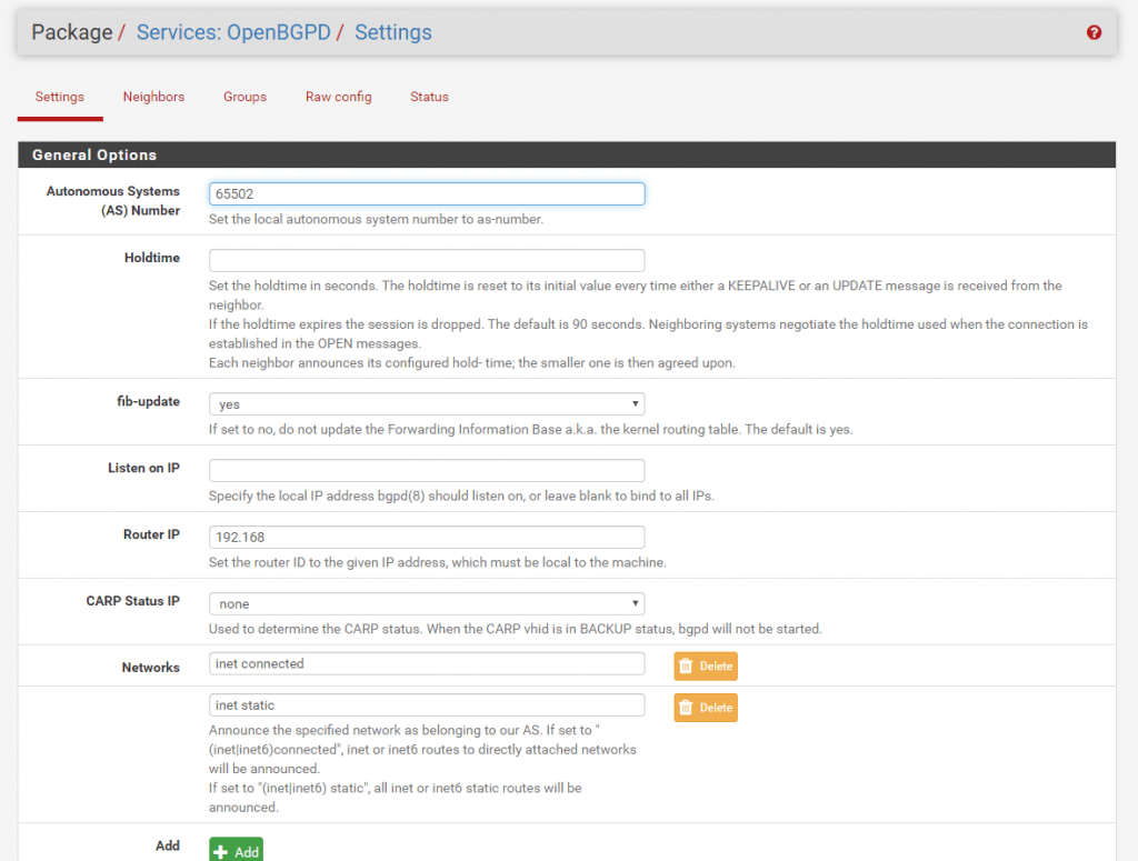
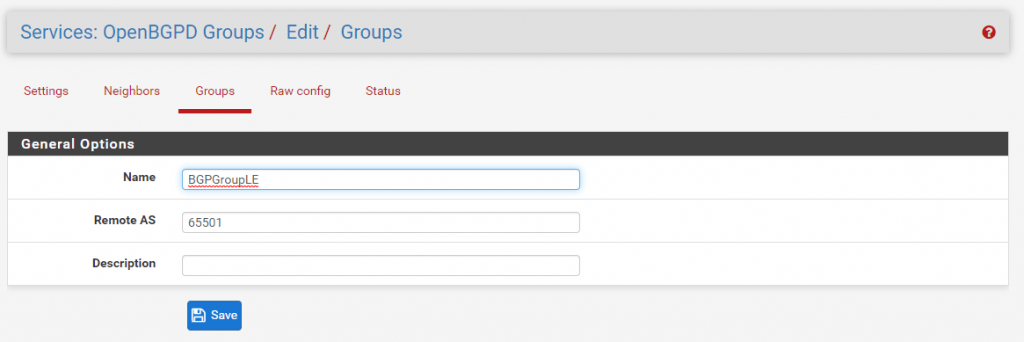
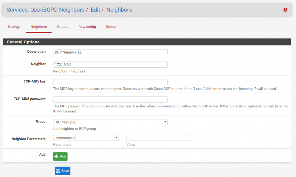
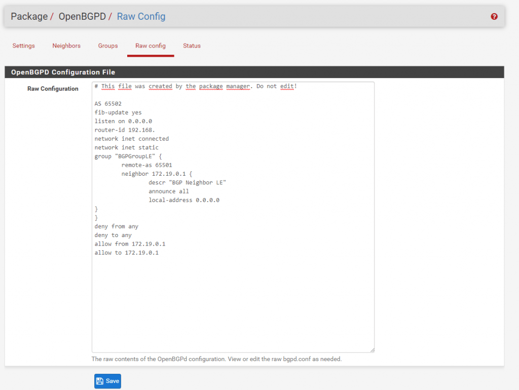
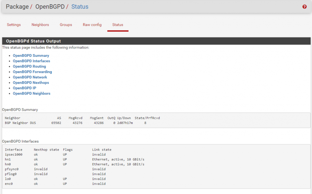
If we configured on both sites the BGP Protocol correct and it works we can see under Status the following informations.
Status from Site A:
Here you can see that BGP is connected to Site B with the AS Number 65502 and is up for two days, seven hours and seventeen minutes.
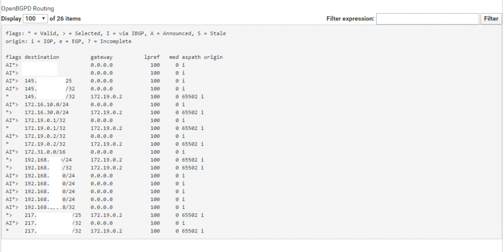
Next you can see the Routing table which contains all routes from its local configuration like direct attached networks and static routes + the routes learned from the BGP Protocol and the remote peer known as BGP Neighbor. This table may be contain more than one entry for a given destination.
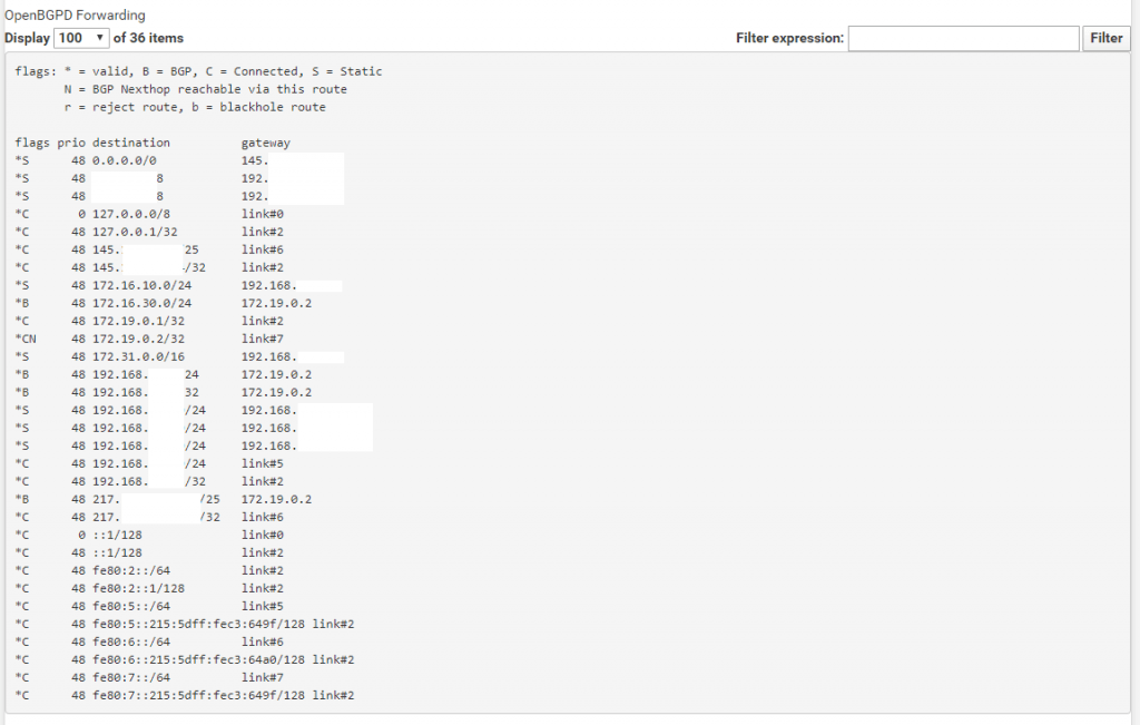
Next you see the Forwarding table which contains the best path for a certain destination based on the previous routing table.
Under https://en.wikipedia.org/wiki/Routing_table you will see the differences between a Routing Table and a Forwarding Table.
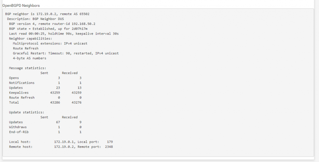
The last check if the routes announced correctly is to look at the Routes under Diagnostics – Routes.
Here you should see the local networks from the remote site and the corresponding Gateway to use.
One last thing we must configure on each site that traffic can flow from the remote site to the local site are the IPSec Firewall Rules .
This rule controls what traffic can flow from the remote site into the local network site known as ingress filtering. Traffic outbound to the remote site you can control with the LAN rules and is known as egress filtering.
https://docs.netgate.com/pfsense/en/latest/book/firewall/ingress-and-egress-filtering.html
With the following Rule you allow all incoming IPv4 traffic from the remote site to the local site. Depending on the remote site if trusted like a branch office or not you can restrict traffic and allow only the required ones.

If you wonder why we do not have to configure an allow rule on the WAN Interface for the IPSec traffic between the pfSense Appliances?
https://docs.netgate.com/pfsense/en/latest/book/ipsec/ipsec-and-firewall-rules.html
When an IPsec tunnel is configured, pfSense® automatically adds hidden firewall rules to allow UDP ports 500 and 4500, and the ESP protocol from the Remote gateway IP address destined to the Interface IP address specified in the tunnel configuration.
UDP Port 4500 is only required for NAT Traversal if the pfSense Applicance doesn’t have a public IP and is behind a NAT device.
That’s it!
Troubleshooting
Troubleshooting IPsec VPNs
Due to the finicky nature of IPsec, it isn’t unusual for trouble to arise. Thankfully there are some basic (and some not so basic) troubleshooting steps that can be employed to track down potential problems.
More you will find under https://docs.netgate.com/pfsense/en/latest/troubleshooting/ipsec.html
Duplicate IPsec SA Entries
In certain cases an IPsec tunnel may show what appear to be duplicate IKE (Phase 1) or Child (Phase 2) security association (SA) entries.
After lengthy testing and research, the main way this starts to happen is when both sides negotiate or renegotiate simultaneously. If both peers initiate, reauthenticate, or rekey Phase 1 at the same time, it can result in duplicate IKE SAs. If both peers rekey Phase 2 at the same time, it can result in duplicate child SAs.
Mitigating this problem involves ensuring that the chance of simultaneous negotiation is minimized or eliminated. The easiest way to reach that goal is to set higher Phase 1 and Phase 2 lifetimes on one peer, or at least make sure both sides are not set identically.
Source: https://docs.netgate.com/pfsense/en/latest/troubleshooting/ipsec-duplicate-sa.html
Related Posts
Latest posts
Deploying NetApp Cloud Volumes ONTAP (CVO) in Azure using NetApp Console (formerly BlueXP) – Part 4 – Antivirus VSCAN Configuration
Follow me on LinkedIn


