Set up an internal LAN and Perimeter Network with public IPv6 Addresses and pfSense
In this post we will see how to set up an internal LAN and perimeter network with public IPv6 addresses, so called IPv6 global unicast addresses. This is nearly the same as in one of my last posts about to set up your internal perimeter network with public IPv4 addresses.
But this time we also use public ip addresses (IPv6) for the internal LAN network, and here for both, servers and clients, what we normally not do with limited available public IPv4 addresses.
At the beginning one point regarding prefix vs. subnet wording in this post
IPv4 has a subnet mask (dotted quad notation) that was later replaced by CIDR masking. IPv6 doesn’t have a subnet mask but instead calls it a Prefix Length, often shortened to Prefix. Prefix length and CIDR masking work similarly; The prefix length denotes how many bits of the address define the network in which it exists.Source: https://docs.netgate.com/pfsense/en/latest/network/ipv6/subnets.html#ipv6-subnetting
So I will use prefix and subnet for one and the same!
Calculating your IPv6 prefixes
Most ISPs are very generous regarding providing large global unicast IPv6 address blocks for their business internet connections. So mostly you will get for your business connection a /48 prefix block of IPv6 addresses which is also the suggested subnet size for a network site, stingier ISPs perhaps only a /56.
In this case you can split the /48 or /56 prefix into multiple /64 prefixes, to be correct, in case of a /48 prefix you will get 65.536 /64 prefixes.
The 16 bits between a /48 and a /64 prefix are most generally being reserved for intra-site addressing (i.e., subnets within sites), and the 16 bits between a /48 and a /32 prefix are generally reserved for inter-site addressing (i.e., subnets between sites).
Source: IPv6 Address Planning by Tom Coffeen
Some ISPs and regarding the internet connection you purchased from them, will only provide you with a /64 prefix.
You can also create multiple further smaller prefixes (IPv6 subnets) from this /64 prefix, but in this case you cannot use IPv6 auto configuration for theses prefixes.
A /64 is a standard size IPv6 subnet as defined by the IETF. It is smallest subnet that can used locally if auto configuration is desired. By design the last 64 bit should identify the interface (host).
The 64-bit interface identifier is either automatically generated from the interface’s MAC address using the modified EUI-64 format, obtained from a DHCPv6 server, automatically established randomly, or assigned manually.
The first 48 bit is used as routing prefix, the following 16 bit or fewer are used as subnet id and the last 64 bit as mentioned for the interface (host).
Typically, an ISP assigns a /64 or smaller subnet to establish service on the WAN. An additional network is routed for LAN use. The size of the allocation depends upon the ISP, but it’s not uncommon to see end users receive at least a /64 and even up to a /48.
IPv6 subnetting a /64 – what will break, and how to work around it?
https://serverfault.com/questions/714890/ipv6-subnetting-a-64-what-will-break-and-how-to-work-around-it
The first thing we have to do, is to calculate our new /64 prefixes from the given /48 or /56 prefix our provider has assigned to us. In my case the ISP has assigned a /48 prefix to me.
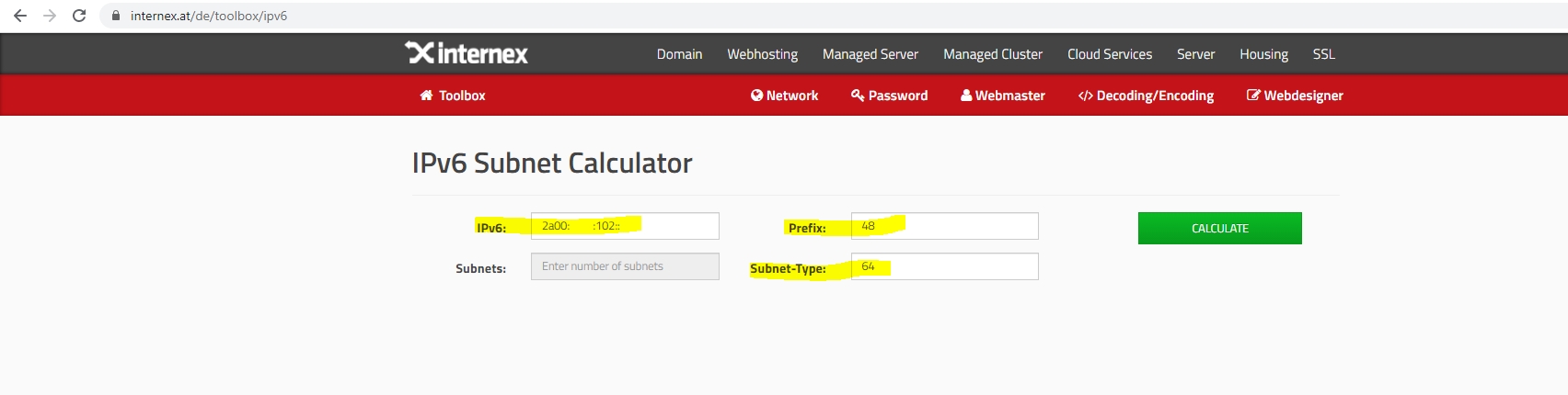
To calculate the /64 prefixes you can use an IPv6 Subnet Calculator like the following.
IPv6 Subnet Calculator
https://www.internex.at/de/toolbox/ipv6
To calculate the /64 prefixes you need to enter the IPv6 network address, the origin prefix length you get from your ISP and finally the prefix length of the new subnets you want, we want /64 prefixes.
After clicking on Calculate you will get a list of all /64 prefixes inside your origin prefix, in my case of a /48 prefix I will get 65.536 /64 prefixes (subnets).
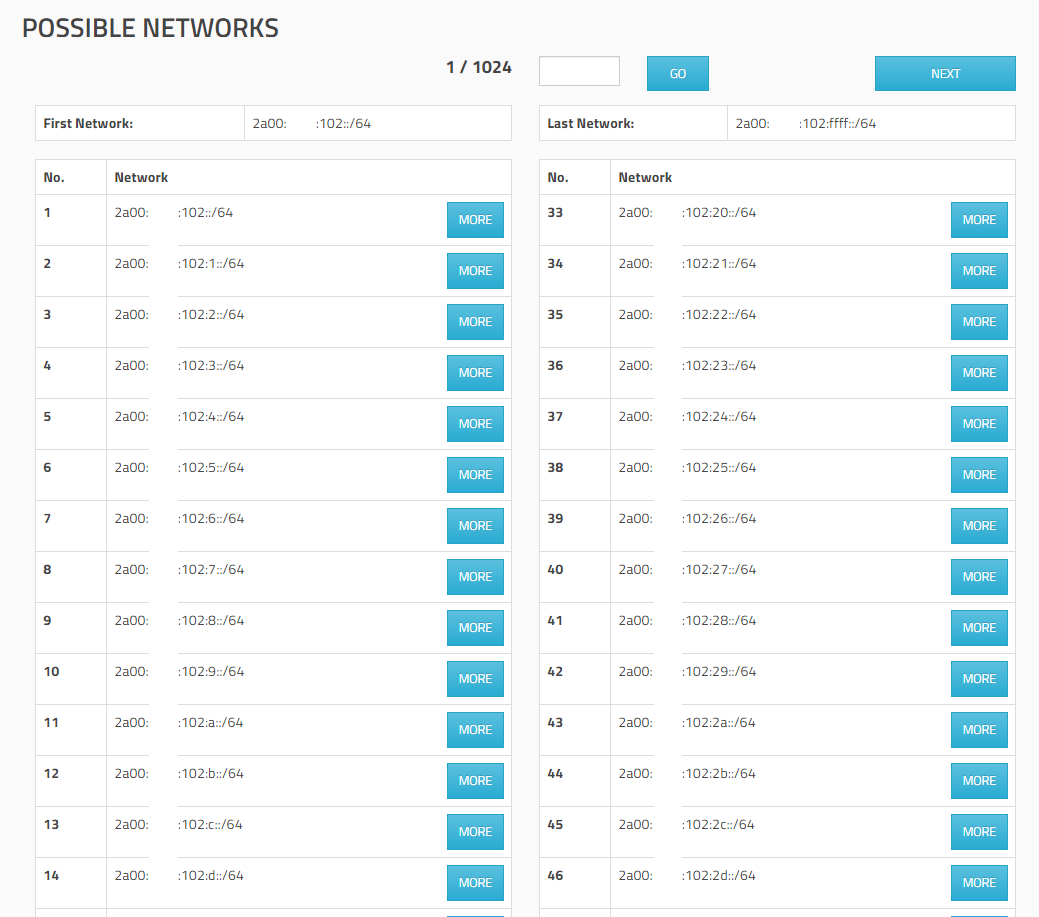
Now we have to choose one /64 prefix, which becomes our WAN prefix (subnet). This have to be the prefix in which IP range the ISP Router (PE = Provider Edge routers) have its own IP address which is our Gateway to route traffic to the WAN.
Usually this is the first /64 prefix and the first usable IP inside this prefix.
Also in my case
WAN Prefix: 2a00:????:102::/64
Gateway IP: 2a00:????:102::1
Long format
2a00:????:0102:0000:0000:0000:0000:0001
Avoid to assign the zero subnet!
As mentioned above, usually the first /64 prefix and the first usable IP inside this prefix, is used by the ISP Router as its own gateway IP to route traffic to and from your prefix.Avoiding assigning the zero subnet, is also a reason why you should prefer a different alternative and currently best practice for creating a WAN link (prefix), by using a /64 prefix from a dedicated pool of IPv6 prefixes.
The first subnet (prefix) of a group of IPv6 subnets is always enumerated with a 0. In the instance where the prefix contains consecutive zeros that allow for prefix zero compression, presentation inconsistency results.
Zero subnets can potentially confuse and cause problems for operational personnel, especially if they’re not paying close attention to the CIDR notation, since the number of characters in the prefixes for both, the main and whole /48 prefix assigned from your ISP to you and your first calculated /64 prefix from it, is the same:
2a00:????:102::/48
2a00:????:102::/64
2a00:????:102::/64 -> reserved and not assigned -> expanded for clarity, 2a00:????:102:0000::/64
2a00:????:102:1::/64 -> first prefix to assign
2a00:????:102:2::/64
2a00:????:102:3::/64
2a00:????:102:4::/64
…
2a00:????:102:ffff::/64To prevent this confusion is to avoid assigning the zero subnet!
Source: IPv6 Address Planning by Tom Coffeen
One better alternative and currently the best practice for creating the WAN link (prefix)!
Instead of using and calculating that /64 wan link (prefix) from the origin large /48 prefix, to put your front firewalls inside, which have to be connected to the same network segment (WAN prefix), as the ISP router’s gateway itself.
Ask your ISP provider to assign you a further dedicated small IPv6 prefix, like a /64 prefix or even smaller, to be the WAN link (prefix) where also the ISP Router have its gateway IP and then route the origin large /48 prefix through this dedicated /64 wan link (prefix) to use it only for your internal networks.
In this case, you can configure the routing for your /48 prefix on your own without asking the ISP to configure any static routes on the ISP router which points to your calculated /64 prefixes.Further you can avoid to assign the zero subnet as mentioned below!
/64 prefix from a dedicated pool of IPv6 prefixes
Using a /64 prefix from a dedicated pool of IPv6 prefixes is the most common scenario and currently the best practice. A separate block of IPv6 space is allocated for the WAN links to the end customer CPEs, so that when CPE connects to the network and performs router discovery, a /64 prefix is used to number both ends of the connection.
Source: https://www.ripe.net/publications/docs/ripe-690#4-1-4—64-prefix-out-of-the-ipv6-prefix-assigned-to-the-end-user
Deutsche Telekom unfortunately will in general not assign you a dedicated /64 prefix for the WAN link (prefix), they will use instead the first /64 prefix out of the /48 prefix for the WAN link (prefix). From the first /64 prefix, they will then use the first IP for the provider side and their own Provider Edge router (PE) as Gateway IP (your upstream gateway to the WAN) and the second IP for the customer side and their Customer Premises Equipment (CPE) router. Afterwards they route the whole /48 prefix to this second IP on the customer side. So you need to assign this second IP on your router by using a /64 subnet prefix length.
In this case you can also configure the whole routing for the remaining prefixes (65.536 minus 1) on your own, but avoiding zero subnet as mentioned before will fail.
This is in contrast to IPv4 also a common practice even if currently not the best practice and described in the following IETF Internet Draft (https://tools.ietf.org/html/draft-palet-v6ops-point2point-01).
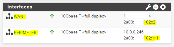
Now as we know what /64 prefix we should use for the WAN subnet, we can assign an IP address from this prefix to our pfSense Appliance and the WAN interface.
We can use every IP address in this prefix besides 2a00:????:102::1, which is assigned to the ISP Router (PE) and represents the gateway from our network to the providers network and therefore to the WAN.
What about the network address and broadcast address from that prefix? Can I also use them?
Unlike IPv4, IPv6 actually allows the use of the network address for a host interface and it has no broadcast, so all network addresses from this prefix can be used for host addressing.
Source: https://networkengineering.stackexchange.com/questions/58000/does-an-ip-address-with-host-part-zeros-represent-a-network-or-a-network-inter
In IPv6, all zeros and all ones are legal values for any field, unless specifically excluded. Specifically, prefixes may contain, or end with, zero-valued fields.
Source: https://datatracker.ietf.org/doc/html/rfc4291In IPv6 instead of having a broadcast address, the same result is achieved by sending a packet to the link-local all nodes multicast group at address ff02::1.
Despite of that fact, I would recommend not to use the all-zeros address as an host address as it can be confusing to distinguish between a prefix and an address like mentioned above also for the zero subnets and in the blog (When is an IPv6 address an address and when is it a prefix?) and Tom Coffeen’s book IPv6 Address Planning from O’Reilly Media.
There are two exceptions to being unable to use the network address for an interface, and those are /31 and /32 networks.
IPv4
An address with an all-zero host portion refers to the network itself, rather than to any particular host.
Historically, this zero host address has served as an alternative broadcast address, and devices still respond that way.
Source: a-host#:~:text=An%20address%20with%20an%20all,devices%20still%20respond%20that%20way.
“For historical reasons many OSes treat the first address as a broadcast. For example, pinging x.x.x.0 from OS X, Linux, and Solaris on my local (/24) network gets responses. Windows doesn’t let you ping the first address by default but you might be able to enable it using the SetIPUseZeroBroadcast WMI method. I wonder if you could get away with using .0 as a host address on an all-Windows network.”.
Why can a network address not be a valid host address?
https://superuser.com/questions/379451/why-can-a-network-address-not-be-a-valid-host-address
IP addresses are not permitted to have the value 0 or -1 for any of the Host-number, Network-number or Subnet-number fields (except in the special cases listed above). This implies that each of these fields will be at least two bits long.
Source: https://tools.ietf.org/html/rfc1122
Configure the Front Firewall
So I will assign the IP 2a00:????:102::2 or in long 2a00:????:0102:0000:0000:0000:0000:0002 to the WAN interface from pfSense my front firewall which is connected to the WAN subnet (network segment) where also the ISP Router (PE) is connected.
Further I need to configure the IPv6 Upstream gateway which is the ISP Router (PE) with the IP 2a00:????:102::1

I will have multiple front firewalls in this wan subnet for multiple purposes and therefore, I can assign further IPv6 addresses from this first /64 prefix to them and the WAN interfaces.
As they all will be in the same network segment (subnet / first /64 prefix, ethernet data link layer 2) with the ISP Router (PE), they can communicate with each other.
When you now assign on the internal (LAN or Perimeter) interface from pfSense, an IPv6 address from one of the other calculated /64 prefixes like No.2 with the prefix 2a00:????:102:1::/64 and the address 2a00:????:102:1::1 from this prefix, the ISP Router (PE) doesn’t know to what next hop (IP address) it should route incoming packets for this IPv6 address.
But why does the ISP Router (PE) not knows where to route the packets to the other /64 prefixes?
Therefore we should know how hosts (nodes) on a network segment at layer 2 (data link layer), Gigabit Ethernet Switch in my case, determine the destination port at the switch to which they should send traffic (frames) for another host (node) connected to this port.
In IPv6 this is nearly the same as in IPv4 with a few differences regarding the protocols they were used to determine the layer 2 MAC address of the host.
How it works in IPv4 I described in the following post as mentioned at the beginning.
To describe the process of determine the layer 2 MAC address and therefore the port from the switch, to which the ISP Router (PE) should send the packets, I will use also a figure but this time with an IPv6 configuration.

As already used in my post about IPv4, I will also send here an ICMP Echo Request (Ping command) out to google.com from our Windows 10 VM homed in the perimeter network.
Please notice, that the above configuration still works in my case for the internal perimeter network and IPv6 address for this No.2 /64 prefix. The reason is that I already asked the ISP to configure static routes to a couple of these /64 prefixes as shown above.
But this doesn’t matter, I will first show regarding the above working configuration how the routing to the other /64 prefixes, besides the first in which the front firewalls + the ISP Router are homed and connected to, works under the hood. Then secondly I will try to send a packet to a /64 prefix which is not configured as static route on the ISP Router and will fail to reach its destination.
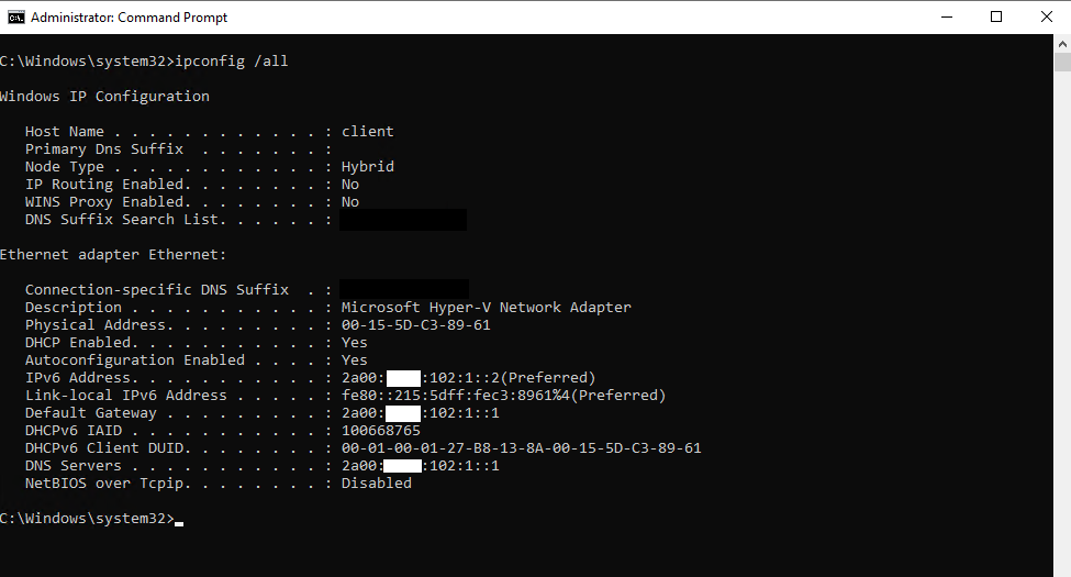
Here you can see the IP configuration from the Windows 10 VM which is homed in the perimeter network.
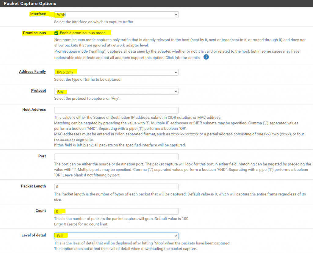
Before we fire up the PING command, we first need to start the packet capture at pfSense, to capture the traffic from the VM to the ISP Router (PE) use the following settings.
So at pfSense we go to Diagnostics – Packet Capture and start the capture with the following settings.
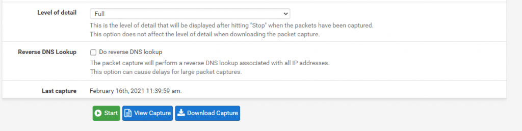
Click on Start
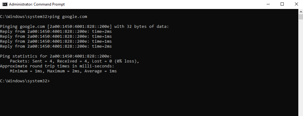
Now we can fire up the PING (ICMP Echo Request) command from our Windows 10 VM in the perimeter network.
As you can see we successfully receive ICMP Echo Reply messages back.
To check this we can now download the Capture from our test and open the cap file with WireShark.
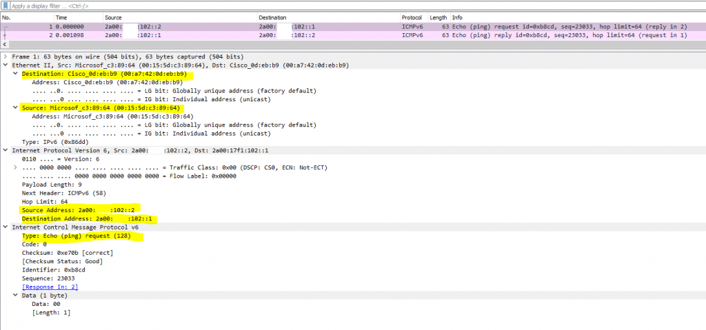
Here we can see nothing spectacular besides the outbound ICMP Echo Request messages from our Windows 10 VM, leaving the WAN interface from pfSense with the IP 2a00:????:102::2 and routed to the ISP Router (PE) which is the gateway and the IP 2a00:????:102::1. As you can see and derived from the MAC address, the ISP Router is from Cisco.
Further you will see the ICMP Echo Reply messages from google.com.
As mentioned here, I want to show you first, why the routing from and to the second /64 prefix (No.2) works as I asked already the provider to set a static route to this /64 prefix on the ISP Router (PE).
I told the provider, that they should configure a static route for the No.2 prefix 2a00:????:102:1::/64, for which the next hop (IP) from their router the IP 2a00:????:102::2 should be, the WAN interface from pfSense. This IP as already mentioned, is located in the same first /64 prefix (from the origin /48 prefix) as also the ISP Router (PE) gateway IP 2a00:????:102::1.
Note!
Best practices is to use as mentioned above a further dedicated IPv6 /64 prefix or the first /64 prefix out of the /48 prefix for the WAN link.For both methods the provider doesn’t need to set static routes for each separate calculated /64 prefix and instead will route the whole /48 prefix either on one of the dedicated /64 prefix IPs configured on your router at the WAN link or one of the IPs from the first /64 prefix out of the /48 prefix also configured on your router at the WAN link.
So when a packet for the No.2 prefix and IP address 2a00:????:102:1::2 (Windows 10 VM inside the perimeter network) hits the ISP Router (PE), in this case the ICMP echo reply packet, the ISP Router (PE) will have a static route to this prefix, where the next hop (IP) is the IP from the WAN interface from pfSense and the IP address 2a00:????:102::2.
So the first thing if not still happened, the ISP Router (PE) needs to determine the data link layer address (MAC Address) from this next hop (IP) 2a00:????:102::2.
Therefore it will first send out an Neighbor Solicitation (NS) message to the IPv6 Multicast address ff02::1:ff00:2 which pfSense is joined at startup.
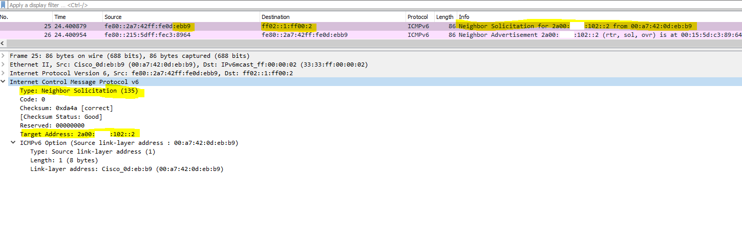
pfSense will then reply to this Neighbor Solicitation (NS) message back with an Neighbor Advertisement (NA) message, which will tell the ISP Router under what data link layer address (MAC) it is available.
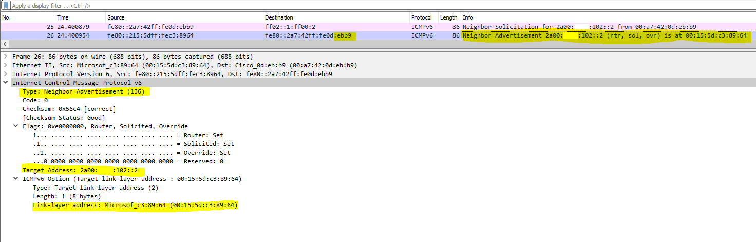
After receiving this NA message, the ISP Router can send out the packets (frames) to this MAC address and pfSense.
pfSense itself of course, is aware that this second /64 prefix is configured on the internal interface and will route the packet to the Windows 10 VM.
But what would be happened, if I didn’t asked the ISP to create a static route for this second prefix pointed to the WAN interface from pfSense?
Or for the best practices method, if the provider didn’t route the whole /48 prefix to one of the IPs from the dedicated /64 prefix configured on my WAN interface from pfSense?
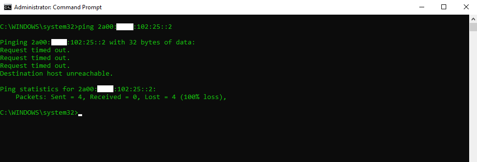
Therefore I will send an ICMP Echo request message from an computer outside over internet to the IPv6 address 2a00:????:102:25::2, which is from the No.38 /64 prefix from the list above, for this prefix doesn’t exist a static route on the ISP Router (PE).
So I didn’t receive any ICMP echo reply messages back, as the packets never hits the destination and not be passed through the ISP Router (PE) to my pfSense front firewall and finally the Windows 10 VM.
As I also captured this try to sending ICMP echo request messages to this IPv6 address and No.38 prefix, for which the ISP Router (PE) doesn’t have a static route entry, we can see what happens under the hood.
Here we can see in the figures below, that the ISP Router (PE) tries to determine the data link layer MAC address for the host with the IPv6 address 2a00:????:102:25::2 (our Windows 10 VM in the perimeter network). Therefore it sends out from his link -local address an Neighbor Solicitation (NS) message to the IPv6 multi cast address ff02::1:ff00:2.
Hosts that have assigned this IP address, should reply with an Neighbor Advertisement (NA) message like
2a00:????:102:25::2 is at 00:15:5d:c3:89:61
back to the requesting host and telling them under what MAC address (data link layer address) it is available. Finally the ISP Router should then send the packet (frame in ethernet layer 2) out to this MAC address and the switch for this network segment, our gigabit ethernet switch to which our pfSense front firewall and the ISP Router is connected, should know the exactly port under which this MAC address is connected to.
A switch builds its MAC address table by recording the MAC address of each device connected to each of its ports. The switch uses the information in the MAC address table to send frames destined for a specific device out the port, which has been assigned to that device.
Source: https://www.ciscopress.com/articles/article.asp?p=2181835&seqNum=5
IPv6 Multicast Addresses
https://www.ciscopress.com/articles/article.asp?p=2803866&seqNum=5
IPv6 uses multicast, including an all-IPv6 devices well-known multicast address and a solicited-node multicast address.
IPv6 Link Local Addresses
https://www.cisco.com/c/en/us/support/docs/ip/ip-version-6-ipv6/113328-ipv6-lla.html
A link-local address is an IPv6 unicast address that can be automatically configured on any interface using the link-local prefix FE80::/10 (1111 1110 10) and the interface identifier in the modified EUI-64 format. Link-local addresses are not necessarily bound to the MAC address (configured in a EUI-64 format). Link-local addresses can also be manually configured in the FE80::/10 format using the ipv6 address link-local command.
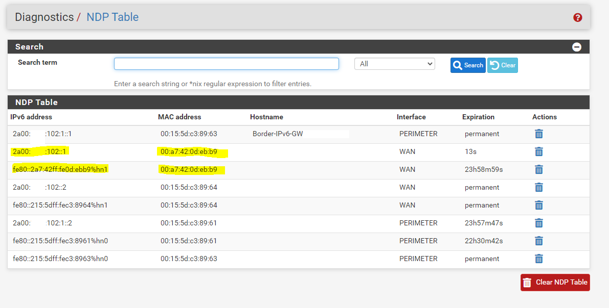
We know, that the link-local address fe80::2a7:42ff:fe0d:ebb9, which is here bound to the MAC address, belongs to the ISP Routers (PE) interface from the NDP Table in pfSense. (second figure below)
The ISP Router (PE) sending the Neighbor Solicitation (NS) message for the IP 2a00:????:102:25::2 to the IPv6 multi cast address ff02::1:ff00:2

Here we can see the MAC address from the public IP which is assigned to the ISP Router and also the local link layer address which belongs to the same MAC address.
WireShark NDP Filter
Router Advertisement
cmpv6.type == 134
Neighbor Solicitation
icmpv6.type == 135
Neighbor Advertisement
cmpv6.type == 136
# filter all of them
icmpv6.type == 134 || icmpv6.type == 135 || icmpv6.type == 136
Unfortunately, the ISP Router (PE) didn’t receive any Neighbor Advertisement (NA) messages back for the IP 2a00:????:102:25::2 and therefore didn’t know to what MAC address it should send the packets (frames).
The reason is, that systems like pfSense, routers generally and also normal hosts configured for routing, didn’t reply by design and for security reasons, to Neighbor Solicitation (NS) messages for IP addresses not assigned directly on the interface, which is connected to the network segment (our gigabit ethernet switch) to what the messages are send.
So the IP address 2a00:????:102:25::2 belongs to No.38 /64 prefix, which is assigned on the internal interface from pfSense, and therefore connected to another network segment (subnet/switch).
And that’s exactly the reason, why on the ISP Router (PE), a static route with the next hop (IP) for this prefix, have to be configured, which have to be the IP from the WAN interface of pfSense.
Or for the best practices method with a dedicated /64 prefix for the WAN link, a static route for the whole /48 prefix with the next hop (IP) from the WAN interface of pfSense, the same if using the method with the first /64 prefix out of the /48 prefix for the WAN link.
In this case, the ISP Router didn’t need to resolve the MAC address for this No.38 prefix IPv6 address, and instead, it only needs to resolve the MAC address for the next hop (IP), which is configured in the static route for this prefix, and is the WAN interface and IP from pfSense.
And because the WAN interfaces IP address is in the same prefix and network segment as the ISP Router (PE), it will reply to Neighbor Solicitation (NS) messages from the ISP Router (PE) as shown above, with the second prefix and setting the static route for it on the ISP Router (PE).
If pfSense now receives these packets, it knows that the destination is reachable through its internal interface and will forward the packets.
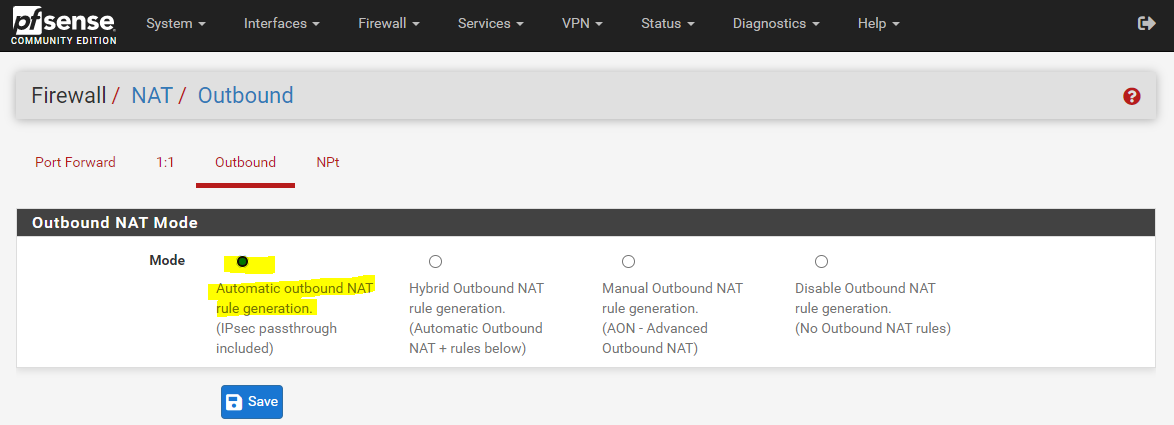
One last point regarding our pfSense front firewall and the WAN subnet. The Firewall -> NAT -> Outbound settings refers only to IPv4 and not IPv6, in IPv6 there is not NAT, only NPt which means Network Prefix Translation and works similar to 1:1 NAT but operates on IPv6 prefixes instead.
As also mentioned in the following documentation from netgate, many question the actual usefulness of NPt as with IPv6 you have enough public IPv6 addresss for your whole network and each host inside, so no workaround or additional layer like NAT for IPv4 or NPt for IPv6 is needed.
As I also configured IPv4 on the front firewall, I will enable Automatic outbound NAT for.
IPv6 Network Prefix Translation (NPt)
https://docs.netgate.com/pfsense/en/latest/nat/npt.html
So if you get an /48 prefix from your ISP, you either use the whole /48 prefix only in the WAN network segment (our gigabit switch) and here for the front firewalls and their WAN interfaces, or you calculate /64 prefixes and tellling the ISP what static routes they have to configure.
The first choice is not really useful as you waste a vast amount of public IPv6 addresses and still need private IPv6 addresses with NPt (IPv6 Network Prefix Translation) for your perimeter and lan network.
The second to create /64 prefixes and tell your ISP to configure static routes to them is one of the choices but also not the best, here regarding how much static routes and therefore how much /64 prefixes you want to use, this can be very cumbersome for your ISP and for each change you have to contact your ISP.
As mentioned at the beginning, One better way is to ask your ISP to provide you a small IPv6 prefix, like a /64 prefix or even smaller, for your WAN subnet (your front firewalls WAN interfaces and the ISP Router), and then route the origin large /48 prefix through this small /64 prefix to use it only for your internal networks.If the provider will not provide you a dedicated /64 prefix for the WAN link, then you should prefer the method to use the first /64 prefix out of the /48 prefix for the WAN link and the provider should also route the whole /48 prefix to one of the IPs from the first /64 prefix and configured on your WAN interface from the front firewall at the WAN link.
In this case you can configure the routing for the /48 prefix on your own without asking your ISP to configure static routes on the ISP router to the calculated /64 prefixes as shown further above.
Configure the Back Firewall
So far we configured the pfSense front firewall with the WAN subnet and the perimeter subnet, further we configured one Windows 10 VM which is placed inside the perimeter network.
Finally we also configure the pfSense back firewall which connects the perimeter network with the internal lan network.
Below you will see the configuration from the interfaces of the pfSense back firewall.
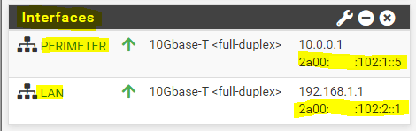
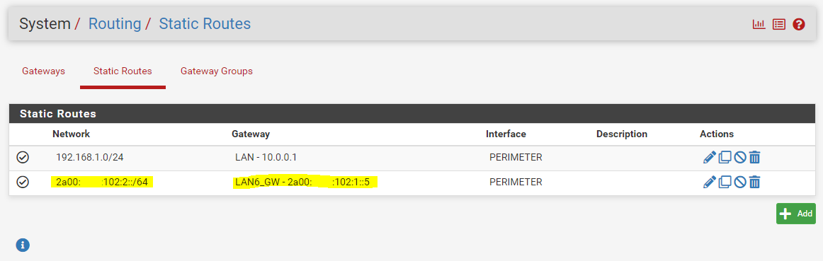
The perimeter interface will become an IPv6 address from the No.2 prefix 2a00:????:102:1::/64 and the IP 2a00:????:102:1::5.
The internal lan interface from the No.3 prefix 2a00:????:102:2::/64 and the IP 2a00:????:102:2::1.
As mentioned further above, for this No.3 prefix, I told the provider to set a static route as done also for the No.2 prefix, with the IP 2a00:????:102::2 as next hop which is the WAN interface from the pfSense front firewall.
In order that the pfSense front firewall can route packets for this prefix/subnet, I configured first a gateway on the front firewall for this No.3 prefix on the internal perimeter interface and the IP from the perimeter interface of the pfSense back firewall.
Note!
For the best practices method with the dedicated /64 prefix for the WAN link and routing the /48 prefix through it, we also need to configure that gateway but in this case for the whole /48 prefix of course.
After that I also configured a static route on the front firewall to this No.3 prefix using the above configured gateway. From now on the pfSense front firewall knows the route to this internal IPv6 lan network and will forward packets for through the pfSense back firewall.
Note!
For the best practices method with the dedicated /64 prefix for the WAN link and routing the /48 prefix through it, we also need to configure a static route but in this case for the whole /48 prefix.
Inside the internal lan network, I will place a further Windows 10 VM with the following IPv6 configuration. The VM is getting of course an IPv6 address from the No.3 prefix with 2a00:????:102:2::2.
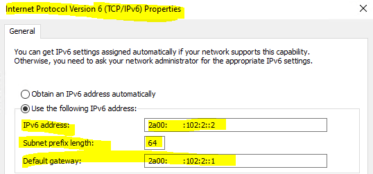
On the VM itself I have nothing to do else in order to get internet access with IPv6, therefor I have to configure a few more things on the pfSense back firewall.
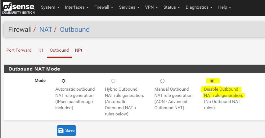
First I will disable Outbound NAT for IPv4, this has nothing to do with our IPv6 scenario but as the configuration supports dual stack with IPv4 an IPv6, I need to disable it in order IPv4 internet access will work.
The back firewall shouldn’t translate the private IPv4 addresses between the lan and perimeter network, only the front firewall should translate the internal private IPv4 addresses into the public IPv4 address from the WAN interface.
Firewall -> NAT -> Outbound
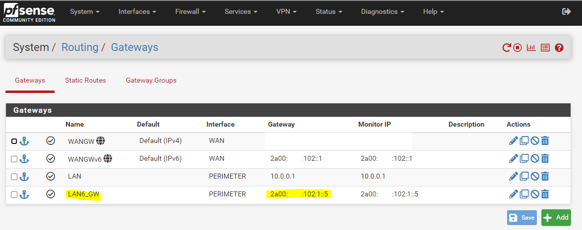
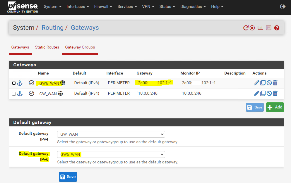
Next I have to create the default IPv6 Gateway for the back firewall. The interface must be the perimeter interface and the IP should be 2a00:????:102:1::1, which is the IP from the internal perimeter interface of the pfSense front firewall. So the back firewall will forward all packets to which it have no direct route, like packets for the WAN, directly to the front firewall and perimeter interface of it.
System -> Routing -> Gateways
The last configuration you have to adjust, are the firewall settings from the back and front firewall. By default all IPv4 and IPv6 traffic outbound is allowed by pfSense from the internal networks assigned to them .
If you want to test, if you can send a PING (ICMP Echo request) packet over the Internet to the internal lan Windows VM, you have to allow ICMP Echo request packets on the external interfaces from the front and back firewall.
Also, if you want to publish some IPv6 services from hosts in the perimeter or internal network, you have to configure only firewall rules on the external interfaces to allow traffic inbound to them.
So to publish internal IPv6 Services, you doesn’t need anymore the NAT Port Forwarding rules.
Read also my following post about numbering the WAN link.
Links
IPv6
https://docs.netgate.com/pfsense/en/latest/network/ipv6/index.html
IPv6 Subnetting
https://docs.netgate.com/pfsense/en/latest/network/ipv6/subnets.html
Analysis of the 64-bit Boundary in IPv6 Addressing
https://tools.ietf.org/html/rfc7421
Multicast address
https://en.wikipedia.org/wiki/Multicast_address
IPv6 Address Representation and Address Types
https://www.ciscopress.com/articles/article.asp?p=2803866&seqNum=5
How do you calculate the prefix, network, subnet, and host numbers?
https://networkengineering.stackexchange.com/questions/7106/how-do-you-calculate-the-prefix-network-subnet-and-host-numbers
When is an IPv6 address an address and when is it a prefix?
https://blogs.infoblox.com/ipv6-coe/when-is-an-ipv6-address-an-address-and-when-is-it-a-prefix/
IPv4 Math
https://networkengineering.stackexchange.com/questions/7106/how-do-you-calculate-the-prefix-network-subnet-and-host-numbers/53994#53994
IPv6 Network Prefix Translation (NPt)
https://docs.netgate.com/pfsense/en/latest/nat/npt.htmlIPv6 Neighbor Discovery
https://blog.apnic.net/2019/10/18/how-to-ipv6-neighbor-discovery