Set up a Perimeter Network with public IPv4 Addresses and pfSense
In this post we will see how to set up a perimeter network with public IPv4 Addresses and pfSense. The configuration and routing for the back firewall which separates the perimeter network with the internal LAN, I will not go through and is not a topic of this post.
For IPv6 you can read my following post.
First I want to mention that I will using the terms Subnet, Network, Address Pool interchangeable in this post, for the Subnet which connects the ISP network with the customer network, I will also use the term WAN link.
Generally you can use private or public IPv4 addresses for your perimeter network. When using private addresses you have to configure Network Address Translation (NAT) to translate the private addresses behind the PERIMETER interface into one of the public addresses assigned to the WAN Interface (WAN link) on pfSense.
If you want to use public IPv4 addresses for your perimeter network and don’t want or cannot deploy NAT with private IPv4 addresses, for what ever reason, some applications are also very NAT unfriendly, we will first need to divide our public IPv4 network (address block), our ISP has assigned to us into more than one subnet.
At least we need two subnets, so that we get two separate network IDs, one for the external WAN interface and subnet (WAN link) and one for the PERIMETER interface and subnet.
For this post I will use my public IPv4 213.61.93.80/29 address pool from my lab network and assigned by Colt.
Btw. if you have also only a /29 subnet from your ISP, it doesn’t really make sense to split this into two /30 subnets in order to use public IPv4 addresses (actually only one address as one of the two available is used for the internal interface on pfSense) in your perimeter network.
But for this post to show what we have to configure, the /29 subnet is good enough.
Dividing this /29 network into two /30 will give me the following subnets
Subnet ID 1: 213.61.93.80/30 with a host range 213.61.93.81 – 213.61.93.82
Subnet ID 2: 213.61.93.84/30 with a host range 213.61.93.85 – 213.61.93.86
Colt has still assigned the IP 213.61.93.81 as gateway for the origin /29 network, so I will use the first subnet id 1 for the WAN interface (WAN link) at pfSense and the subnet id 2 for the perimeter network.
For larger networks and multiple subnets you can use a subnet calculator like the following
https://www.site24x7.com/tools/ipv4-subnetcalculator.html
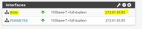
As mentioned I will use the first subnet id 1 for the WAN interface and subnet. From this subnet only one IP address 213.61.93.82 is left to use for the WAN interface. So the addresses from the subnet id 1 are as follows.
This subnet is also called WAN link.
- 213.61.93.80 Subnet Address
- 213.61.93.81 Gateway Address
- 213.61.93.82 WAN Interface pfSense
- 213.61.93.83 Broadcast Address
For the IPv4 Upstream gateway in pfSense, we have to use the 213.61.93.81 address which is configured from Colt as gateway for the whole /29 subnet on their Provider Edge Router (PE).
This Gateway IP is still in the range of the new first /30 subnet we will use for the WAN interface and WAN link.

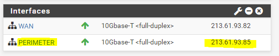
For the PERIMETER subnet I will use the second subnet id 2. From this subnet I can use two IP addresses, one for the PERIMETER interface on pfSense and one for a virtual machine in the perimeter network. So the addresses from the subnet id 2 are as follows.
- 213.61.93.84 Subnet Address
- 213.61.93.85 Perimeter Interface pfSense
- 213.61.93.86 Virtual Machine inside the Perimeter Network
- 213.61.93.87 Broadcast Address
For the internal perimeter interface we do not assign a gateway as usual, here you can assign static routes to your internal LAN.

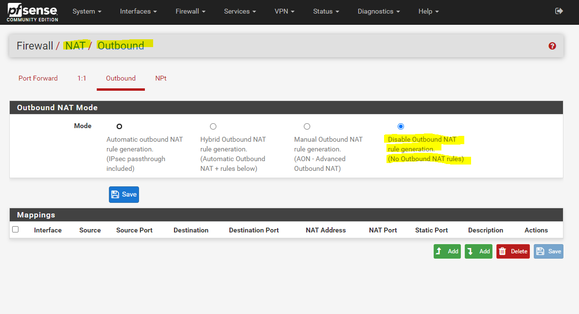
Next we should disable NAT Outbound if we want to use public IPv4 addresses inside our perimeter network. With public IPv4 addresses, we just have to route the traffic without the need to translate the addresses.
Btw. you can of course also use NAT for your public IPv4 addresses inside the perimeter network, which then will be translated into the public IPv4 addresses from the WAN interface, but this doesn’t really make sense and would waste public IPv4 addresses.
So go to Firewall – NAT – Outbound and select Disable Outbound NAT. Not to mention that we also doesn’t need Port Forwarding anymore. From now on we just route and filter the traffic from the WAN interface and subnet to the PERIMETER interface and subnet and vice versa.
Finally, that the routing from and into our perimeter network with the public IPv4 subnet will work, we need to configure the WAN link and can therefore choose between three options, the most common used and best practice is to use a further small dedicated IPv4 subnet, through which the larger IPv4 address pool (subnet) will be routed.
We will see the option with the dedicated IPv4 subnet in detail at the end of this post, as you then will better understand, why you should prefer this option.
At the moment, the ISP Router from Colt doesn’t know how to route traffic for the second subnet id 2 (213.61.93.84/30), we created from the origin /29 subnet for our perimeter network.
Actually the ISP Router doesn’t know how to route the whole /29 subnet at all. But this is no problem until it will not be divided (subnetting) into multiple smaller subnets. The reason for is, that our router (pfSense) on the WAN link, will have configured before subnetting the whole /29 subnet mask on its WAN interface (WAN link). If now the ISP Router received a packet for an IP address within this /29 subnet, it will send out an ARP request on layer 2 to the WAN link (switch), to determine the node (destination port on the switch for the packet) and its physical mac address, which have configured this IP address. If this IP address is configured on the WAN interface or as IP alias in pfSense, and this IP is in the range of the configured subnet mask from the WAN interface, pfSense will reply to this ARP request with an ARP reply message which includes its physical mac address. After that the ISP router will send the packets to this layer 2 mac address and the WAN link (switch) uses its MAC address table to determine the destination port and node this mac address is assigned to and will send the packet to it.If pfSense after subnetting have configured the correct /30 subnet mask on its WAN interface (WAN link), it will not reply to ARP request messages for IP addresses, they will not be in the range of its configured subnet mask on the WAN interface. Even if one of these IP addresses out of the range is configured on its internal perimeter interface, this is by design for security reasons.
You also cannot configure the whole /29 subnet mask on the WAN interface, in order to reply to all ARP request messages for IP addresses from the whole /29 subnet. Then you wouldn’t be able to configure the second subnet id 2 on the internal perimeter interface, in this case the IP addresses would overlap both subnets and you will get an error message like this:
IPv4 address (213.61.93.82/29) WAN interface is being used by or overlaps with: Perimeter interface (213.61.93.85/30)More about these ARP request and reply messages on the WAN link, to determine the destination to send IP packets out to the WAN link, we will see further below.
The first subnet id 1 with our WAN interface from pfSense is still in the range from the ISP gateway with the IP 213.61.93.81, despite the fact that the subnet mask has changed from 29/ into /30.
So what are the first two options, to tell the ISP Router the next hop for the second subnet id 2, which have to be the WAN interface and IP 213.61.93.82 from pfSense?
The first option not really common used in practice, is to tell your ISP to what IP (next hop) it should route the second subnet id 2. So in my case, I should tell the ISP, that he should route the subnet 213.61.93.84/30 to my WAN interface on pfSense with the IP 213.61.93.82.
To simplify this, the ISP could also route the whole /29 subnet to the WAN interface on pfSense with the IP 213.61.93.82. That makes even more sense for a large subnet, which will be divided (subnetting) into multiple smaller subnets, so the ISP only needs to configure one static route for the whole large subnet, which points to an IP from the first smaller subnet (WAN link), assigned on the customers Router (CPE) WAN interface, instead for each smaller subnets. This is also in practice not common used but much more effective then configuring multiple static routes for each smaller subnet.
More about assigning IPs to the WAN link, you will also find in my following post.
The second option is much more a workaround, in case you cannot tell your ISP to set a static route to the second perimeter subnet, or in case of a larger subnet divided into multiple smaller subnets, to set a static route for the whole large subnet.
In pfSense you can create different types of virtual IPs on the WAN interface.
Virtual IP Address Feature Comparison
https://pfsense-docs.readthedocs.io/en/latest/firewall/virtual-ip-address-feature-comparison.html
To publish more than the assigned public IPv4 on the WAN interface, you can use virtual IPs from the type IP Alias.
They will be used in a classic NAT deployment, where you use private IPv4 addresses in your perimeter or LAN network. So with the IP Aliases, you have more than one public IPv4 on the WAN interface (WAN link) assigned and can therefore publish multiple systems listening on the same public port number.
But in what we are interested, to tell the ISP Router the next hop for our perimeter subnet id 2, are virtual IPs from the type Proxy ARP.
As I only have one public IPv4 address in my perimeter network, besides the PERIMETER interface from pfSense, I just need to add my public IPv4 address 213.61.93.86, which will use the VM in the perimeter network, as Proxy ARP address.
You could also add the whole /30 subnet as Proxy ARP address, or whatever size your internal subnet is, but in my case I only have one IP address left I can use, so I will select a /32 subnet mask which stands for a host address.
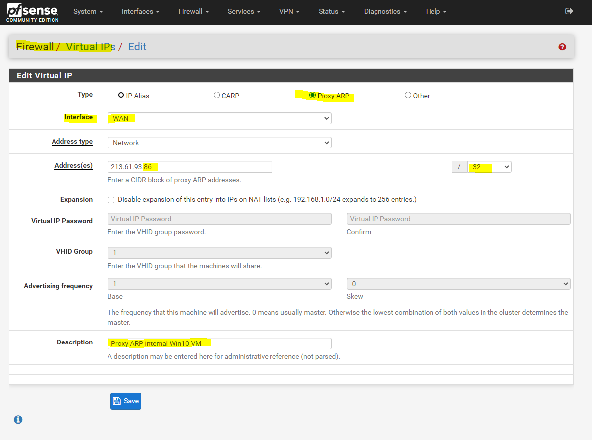
From now on pfSense also replies to ARP requests on Layer 2 from the ISP Router for IPs from the second internal subnet.
Therefore the ISP Router knows that it needs to route traffic for the internal perimeter subnet directly to the WAN interface (WAN link) and IP 213.61.93.82 from pfSense.
Therefore the routing and connection to and from the internet also works from now on.
But why does this work and what’s all behind this two methods?
Therefore we should know how hosts (nodes) on a network segment at layer 2 (data link layer), Gigabit Ethernet Switch in my case, determine the destination port at the switch to which they should send traffic for another host (node) connected to this port.
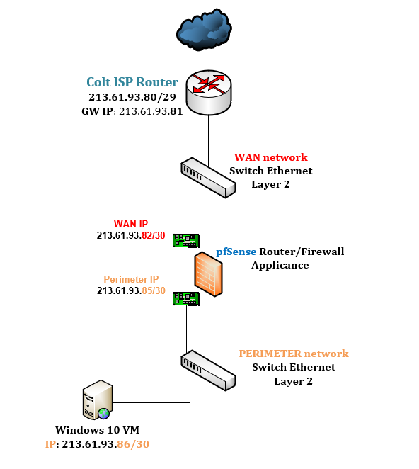
The following figure shows our configuration with the perimeter network.
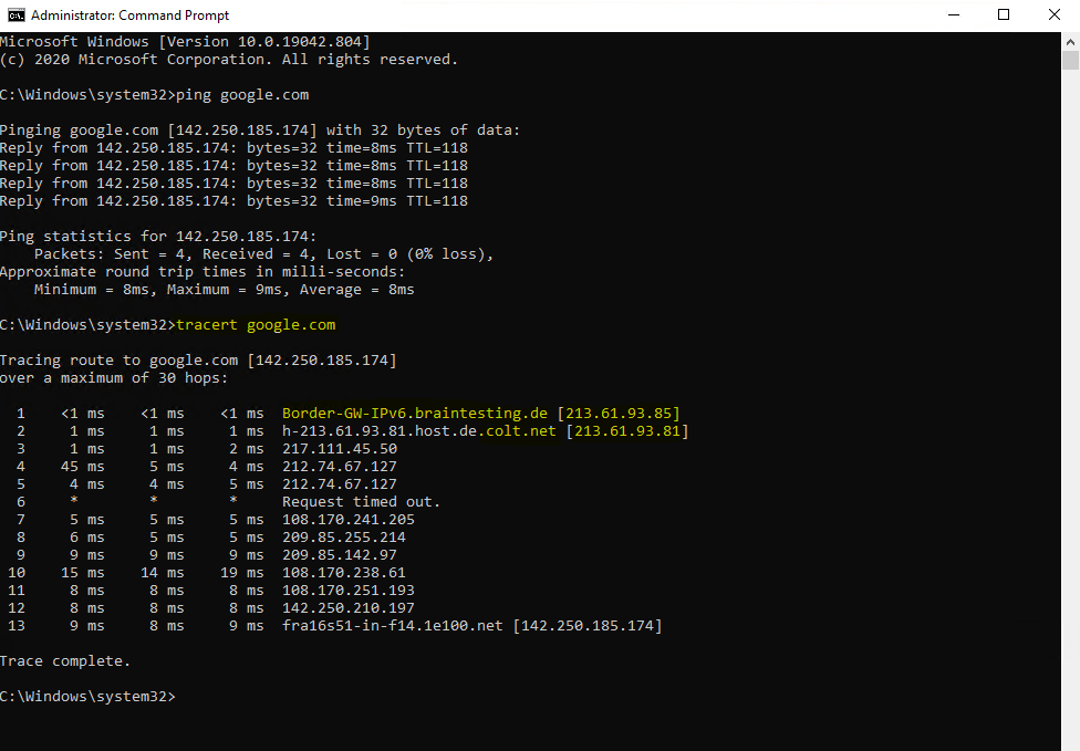
To better understand what’s happening under the hood, we sends out an ICMP Echo Request (Ping command) to google.com from our Windows 10 VM homed in the perimeter network.
First we try this without configuring one of the two options with the new route at the ISP Router from Colt for our perimeter subnet id 2 or the ARP Proxy setting. So in this case, the Colt Router doesn’t know the route to our perimeter network.
Let’s see what happens.
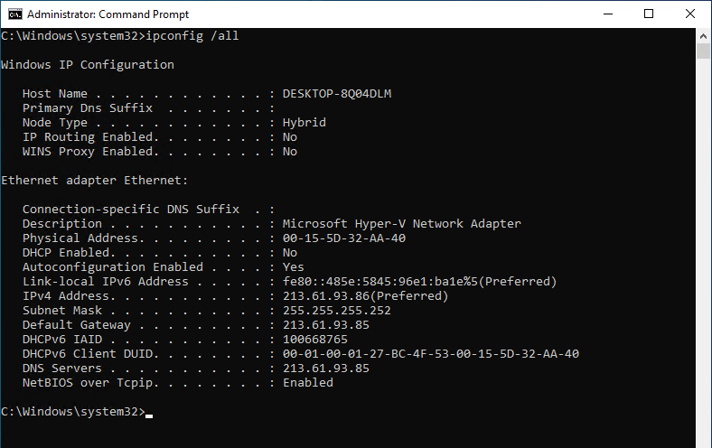
Here you can see the IP configuration from the Windows 10 VM.
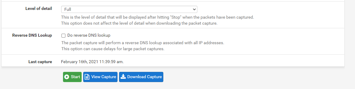
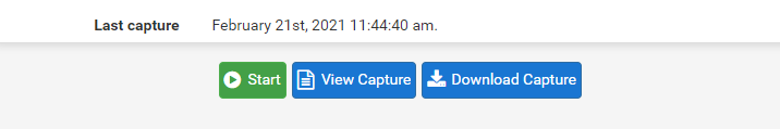
Before we fire up the PING command, we first need to start the packet capture at pfSense, to capture the traffic from the VM to the Colt ISP Router use the following settings.
So at pfSense we go to Diagnostics – Packet Capture and start the capture with the following settings.

Click on Start
Now we can fire up the PING (ICMP Echo Request) command from our Windows 10 VM in the perimeter network.
As you can see we didn’t get any ICMP Echo Reply messages back, at least pfSense resolved the FQDN google.com for us into an valid IP address.
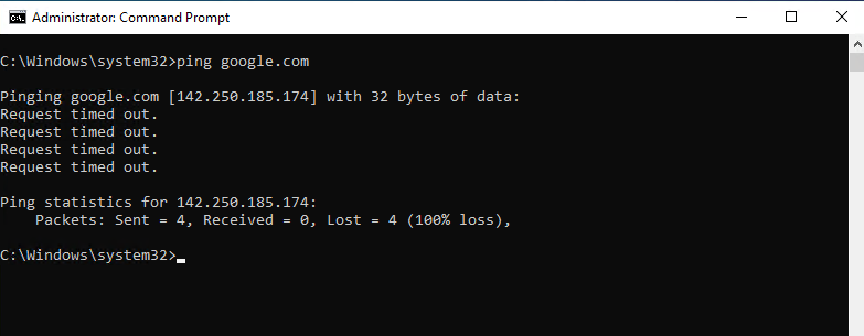
And the reason is not related to the firewall settings, outbound traffic from the perimeter network to WAN is generally allowed.
So as mentioned the reason is the missing route to the perimeter network on the ISP Colt Router.
To check this we can now download the Capture from our test and open the cap file with WireShark.
Here we can see that pfSense correctly forwards our ICMP Echo Request packets to the Colt ISP Router but doesn’t get any response back.
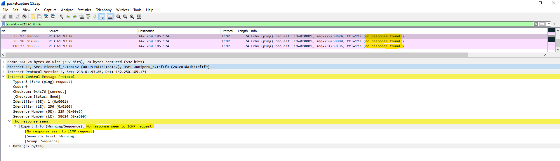
We also can see the destination JuniperN_b7:3f:f0 (28:c0:da:b7:3f:f0), pfSense forwards our ICMP Echo Request packets towards, which is our ISP Colt Router with the gateway IP 213.61.93.81.

To be sure we can check this with the ARP Table at pfSense to determine the corresponding IP address to this MAC address as follows.
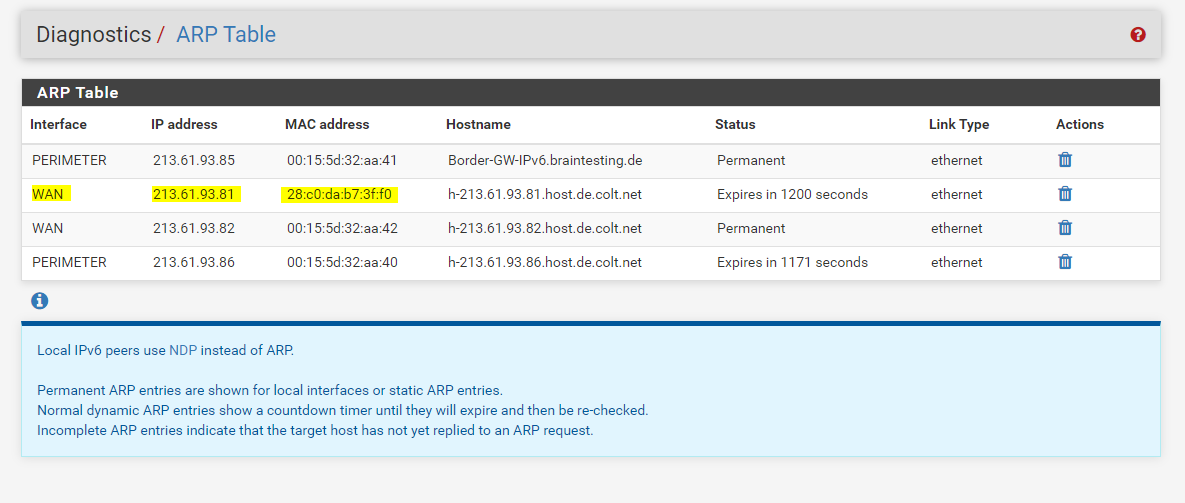
So the Colt ISP Router doesn’t send back the ICMP Echo Request packets, because he doesn’t knows the correct route and next hop for our perimeter network 213.61.93.84/30 and the source IP inside from the Windows 10 VM 213.61.93.86/30.
To show you how the Colt ISP Router with the gateway IP 213.61.93.81/29 and MAC Address 28:c0:da:b7:3f:f0 tries to determine the next hop for the perimeter network, I will have to start a second packet capture at pfSense during the Windows 10 VM is starting up.
Therefore I will first shutdown the VM and after it is turned off, I will start a second packet capture at pfSense and start the VM again.
The settings for the packet capture btw. will be exactly the same as for the first time and above.
After downloading and opening the cap file with WireShark, we can filter the traffic for ARP messages.
Here we can see two interesting ARP Broadcast messages sends out from the Colt ISP Router 213.61.93.81 for the IP addresses 213.61.93.86 (our Windows 10 VM) and 213.61.93.85 (the PERIMETER interface from pfSense)
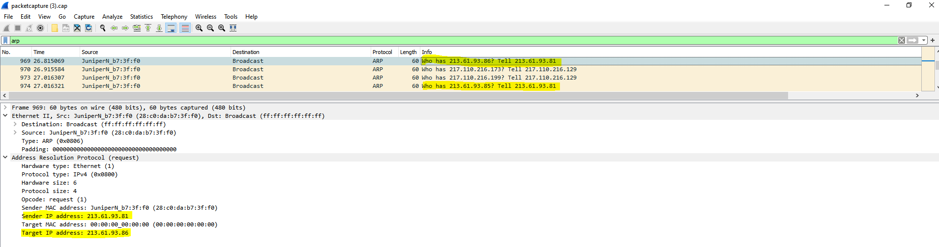
With ARP request messages, the Colt ISP Router tries to determine the MAC address for the requested IPs and therefore the final destination port in his own network segment (WAN Switch) he should submit the packets directly.
You can see that the Colt ISP Router sends the ARP request to the Broadcast address and therefore to all nodes in this network segment (WAN Switch).
Normally the node with the requested IP should send an ARP reply message back like 213.61.93.86 is at 00:15:5d:32:aa:42
As this IP is homed on the internal side and perimeter network of pfSense, pfSense wouldn’t reply by design and for security reasons to such requests for internal IPs and therefore the ISP Router doesn’t get any reply to his requests and don’t know where to route the packets back.
On the other side, if at the Colt ISP Router where configured a static route with the next hop for the perimeter network where this IP is homed, pointed to the WAN interface from pfSense, pfSense would accept the packets and route them to the perimeter network.
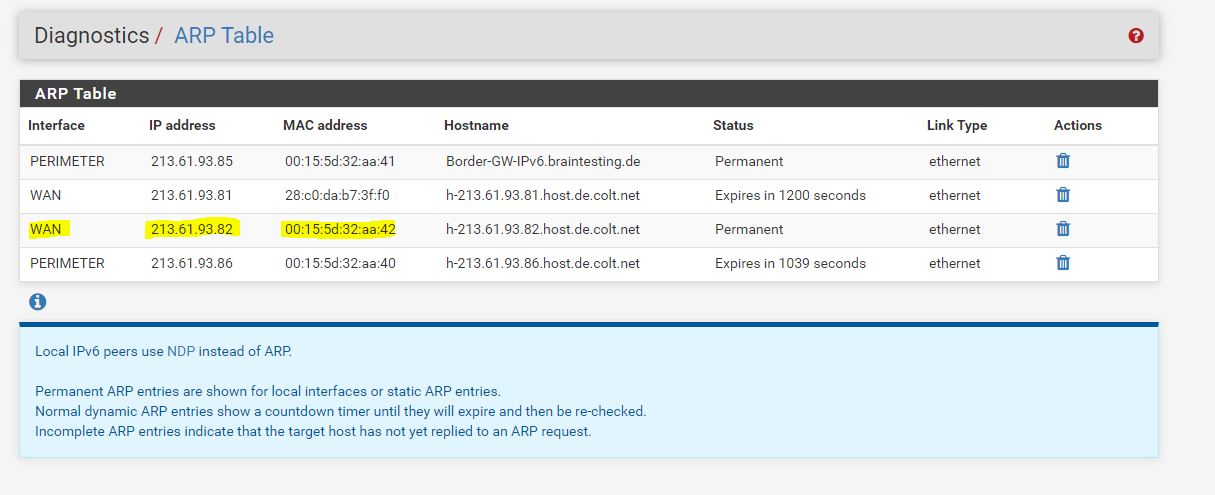
If we configured the mentioned ARP Proxy at the WAN interface, pfSense will reply to ARP Requests for this IP.
To show you how pfSense in this case would reply with ARP reply messages, we have to capture another time the packets from the WAN interface. This time we have to wait a little bit longer as for the ARP request messages. The reason for is the default arp timeout value from Juniper with 21600 seconds (6 hours) . So in this case the Colt ISP Router holds the MAC address for this IP in his cache before he sends out a further ARP request message.
Juniper NETWORKS – TechLibrary
arp timeout
https://www.juniper.net/documentation/en_US/junose15.1/topics/reference/command-summary/arp-timeout.html
Finally I captured an ARP reply message back to the Colt ISP Router from the WAN interface from pfSense as follows. As mentioned, pfSense only replies here because we added the public IPv4 address as Proxy ARP address.
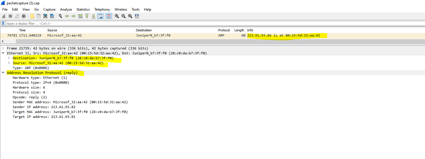
Here you can see that the MAC address in the ARP reply message belongs to the IP from the WAN interface from pfSense.
As mentioned further above about the three options regarding the routing and subnetting for your IPv4 network, the third is the most common used and also best practice in case of a large network address pool is the following:
If your ISP provides you with a large IPv4 network, like a /24 subnet or even more, the best is to ask, if you can get an additional further small dedicated IPv4 subnet, like a /30 subnet, through which your ISP routes the whole large /24 subnet.
From this /30 subnet, one IP is configured on the ISP Router as gateway, in most cases the first IP, and one IP is configured on your front firewall and its WAN interface, so both router (ISP and CPE) are connected to the WAN link with an IP from this dedicated /30 subnet.Your ISP can then set a static route for the actual whole large /24 subnet, with a next hop to the second IP from the /30 subnet, which is assigned on your front firewalls WAN interface.
On your front firewall now all packets for the whole /24 subnet will hit the WAN interface, therefore you can configure on this front firewall the whole routing and subnetting for this large address pool (subnet).
Using an additional dedicated smaller subnet, through which the actual larger IPv4 address pool (subnet) is routed, will give you the benefit, to be independent from your ISP regarding configuring the routing and subnetting for this network. You also doesn’t need to waste IPs from this pool for the WAN link itself, as with option one mentioned further above.
As already mentioned above, you can also read my following post about the options to numbering the WAN link.
Links
Virtual IP Address Feature Comparison
https://pfsense-docs.readthedocs.io/en/latest/firewall/virtual-ip-address-feature-comparison.html
Proxy ARP
https://en.wikipedia.org/wiki/Proxy_ARP
Common Address Redundancy Protocol (CARP)
https://de.wikipedia.org/wiki/Common_Address_Redundancy_Protocol
IP aliasing
https://en.wikipedia.org/wiki/IP_aliasing
IPv4 Math
https://networkengineering.stackexchange.com/questions/7106/how-do-you-calculate-the-prefix-network-subnet-and-host-numbers/53994#53994