Step-by-Step Guide: Setting up HA VPN with BGP between Google Cloud and On-Prem by using Juniper vSRX3
In this post we will see step by step how to set up HA VPN and BGP between our Google Cloud VPC and our on-premise network by using the Juniper vSRX3 Appliance as VPN device.
I wrote already a post in 2022 about how to set up this with pfSense as on-premise VPN device.
GCP Cloud VPN offers two types of Cloud VPN gateways, HA VPN and Classic VPN.
Classic VPN was in 2022 already partial deprecated and therefore I was using HA VPN.
Meanwhile as of August 1, 2025, so just a few days ago of writing this post, the creation of Classic VPN tunnels using dynamic routing (BGP) is no longer supported, regardless of the gateway the tunnel connects to. This includes connections to VPN gateway software running inside a Compute Engine virtual machine (VM) instance or connections outside of Google Cloud.
!! Note !!
Classic VPN tunnels using static routing from Classic VPN gateways to on-premises VPN gateways and from on-premises VPN gateways to Classic VPN gateways are still supported.Google recommends that you only retain Classic VPN if your on-premises VPN devices don’t support BGP, and therefore HA VPN cannot be used.
So we will also see in this post how to set up the HA VPN and BGP in GCP and connect it with our on-premise network by using here the Juniper vSRX3 Appliance as VPN device.
About how to setup the Juniper vSRX3 appliance with the initial setup and network interface assignment and configuration to allow outbound internet access for internal hosts, you can also read my following post.
It also shows how to publish internal services like a web server to the Internet.
And about how to set up step by step a Classic VPN with static routes between Google Cloud Platform (GCP) and an on-premises Juniper vSRX3 appliance you will see in my following post.
- Introduction
- IPSec route-based VPN Tunnel – How Phase 1 and Phase 2 works?
- Cloud VPN Limitations
- Select or create a Project to deploy the HA VPN Gateway
- Creating VPC Network
- Create Virtual Machine Instance
- Set up the Tunnel in GCP
- Set up the Tunnel on Juniper by using the CLI
- Enable and Configure BGP on Juniper vSRX3
- Verify BGP is working
- Links
Introduction
About general information about HA VPN in GCP, you can read my following post and will skip this here.
IPSec route-based VPN Tunnel – How Phase 1 and Phase 2 works?
IPSec Phase 1 – How it works?
First of all IPSec phase 1 works identical for route-based and policy-based VPNs.
The difference between the two models only shows up in Phase 2:
- Policy-based: Phase 2 SAs are built for specific source/destination subnets defined in the policy.
- Route-based: Phase 2 SAs are built for the “tunnel interface” (usually a /30 or /31 network), and routing (static or dynamic, e.g., BGP) decides what goes through.
The purpose for phase 1 is to build a secure control channel between the two VPN endpoints.
How:
- Peers authenticate each other (pre-shared key or certificates).
- Negotiate encryption, integrity, DH group, lifetime, etc. (IKE proposals).
- Derive shared keys.
- Establish the IKE SA (Security Association).
A single, encrypted, bidirectional “management” tunnel, used only to negotiate/manage Phase 2 SAs. No data traffic yet, only control traffic (IKE packets) flows in Phase 1.
Once Phase 1 is up, Phase 2 can start and build the ESP tunnel for actual traffic.
IPSec Phase 2 (route-based) VPN – How it works?
When we bring up Phase 1 (IKE SA), we’re not yet sending user traffic. What we have at this point is:
- A secure, authenticated channel between our Juniper and GCP VPN gateways.
- They can now negotiate Phase 2 (IPsec SAs) inside this channel without fear of eavesdropping.
At this stage, there are no tunnel interfaces yet in Junos carrying user traffic, just the IKE daemon talking to the peer.
Now phase 2 to build the “pipe” for the actual traffic (routed subnets through the tunnel).
In Phase 2, the two peers agree on:
- The IPsec protocol (ESP in your case)
- Encryption/authentication algorithms (ciphers) for data traffic
- The traffic selectors — i.e., which local & remote networks are routed
- A virtual point-to-point link between them (our /30 network/subnet)
In route-based VPNs (like vSRX and GCP HA VPN):
- You bind the IPsec SA (phase 2) to a tunnel interface (st0.0 in Junos).
- That tunnel interface behaves just like an Ethernet point-to-point link between two routers.
In phase 2 (route based) we use /30 subnets & APIPA addresses for the transit network (“pipe”) through which all configured (traffic selectors) subnets will be routed between both peers.
A /30 network gives you exactly two usable IP addresses:
- One for the local tunnel endpoint (our Juniper st0.0 address).
- One for the remote tunnel endpoint (GCP’s internal tunnel interface address).
These addresses only exist logically inside the IPsec tunnel. They aren’t visible on the Internet, they’re carried inside ESP packets that are encapsulated and encrypted.
For this /30 subnet we can choose from:
- APIPA (169.254.x.x/30) — often used to avoid conflicts with real internal networks.
- RFC1918 private addresses (10.x.x.x/30, 192.168.x.x/30, 172.16(-31).x.x/30), also fine if we make sure they don’t overlap with existing configured networks on both sides.
Once Phase 1 is up, the two peers can route any IP addressing scheme over the tunnel, because the ESP encapsulation hides it from the outside world.
The routing between both sides will work as follows:
Both sides have routing tables:
- Local LAN subnets → next hop = tunnel peer inside /30
- Remote LAN subnets → learned via static routes or BGP using that /30 link.
Any packet routed via the tunnel interface:
- Hits the st0.0 interface in Junos.
- Gets encrypted by ESP according to Phase 2 SAs.
- Is sent out via the physical WAN interface (e.g., ge-0/0/1) to the peer’s public IP.
- The peer decrypts it and forwards it into its routing table.
GCP behave like:
- GCP’s HA VPN always assigns a /30 link subnet for the tunnel.
- That /30 is used both for BGP and as the transit network for static routes, unlike Azure, which separates BGP peer IPs from the actual tunnel interface addressing.
- You’re free to use APIPA or private space for that /30, GCP prefers APIPA by default to avoid conflicts.
Phase 2 simply turns the IKE Phase 1 control channel into a routed point-to-point network between two virtual interfaces.
The addressing scheme is entirely under your control as long as both ends match, APIPA is just the safest choice to avoid overlap.
Cloud VPN Limitations
Cloud VPN does not support routing public internet traffic through on-premises like in Azure.
If you need centralized inspection in GCP, you’d typically deploy firewall/inspection appliances inside a hub VPC, not route traffic out through Cloud VPN.
Select or create a Project to deploy the HA VPN Gateway
In GCP, a Project is the main container for all your resources (VMs, networks, storage, APIs, IAM settings, billing).
In Azure, the closest equivalent is a resource group, but that’s not a perfect match because in Azure, the resource groups live inside a subscription, while in GCP a Project is the unit that’s tied directly to billing and IAM.
- GCP Project = Azure Subscription + Resource Group combined into one billing + IAM boundary
- Inside a GCP Project, you still organize resources, but the project itself is the smallest fully isolated unit, you can’t share VPC networks across projects without explicit peering, for example.
About how to create a new project you can also read my previous post.
I will create a new project in GCP for this post to create within a new VPC network and running virtual machine.
Our goal is to be able to later connect to this virtual machine through the IPSec VPN tunnel and vice versa from the GCP virtual machine to an on-premise virtual machine.
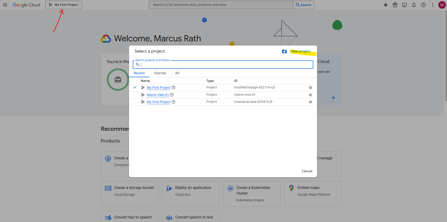
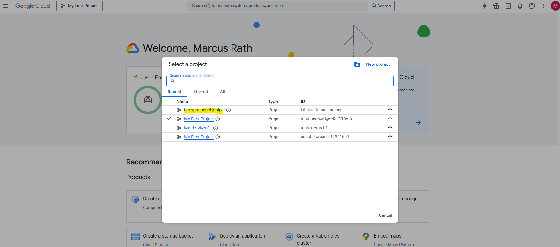
To create a new project we need to click on the top left so called Project selector and on the opened pop-up windows on New project like shown below.
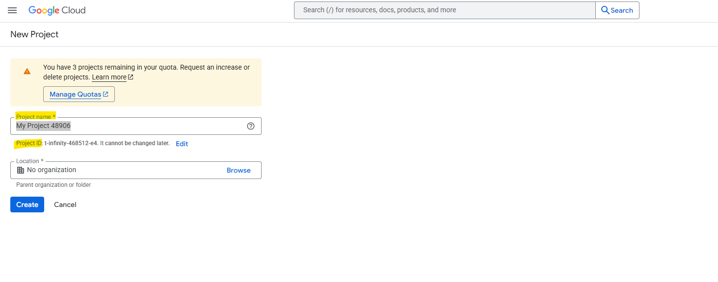
For the project name we can either leave the default suggested name or we use our own custom name.
The project name is human-readable and can be changed later, up to 30 chars. The Project ID is unique and a permanent identifier for APIs/CLI which cannot be changed once set.
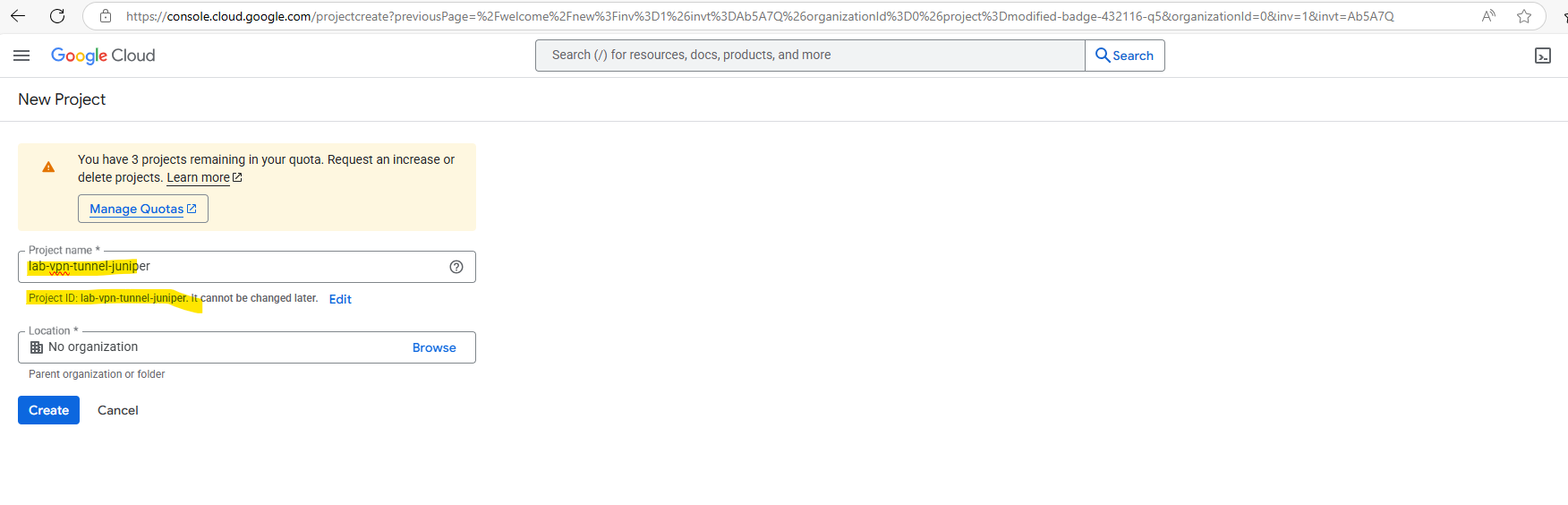
For the project name often the following format is used:
[Org/Team]-[Environment]-[Workload/Service]
For example the following names:
- it-prod-vpn-gateway
- devops-dev-k8s-cluster
- marketing-test-analytics
We can also set the Location for our new project which by default is set here to No organization.
I haven’t created an organization in my lab’s Google account and will leave the location to No organization.
GCP Organization → root node for projects, folders, IAM, and policies, linked to a company domain.
More about the Organization object in GCP, you will find in my following post.
So finally create the project, the project id will be by default the same as the name but we can change it once as mentioned.

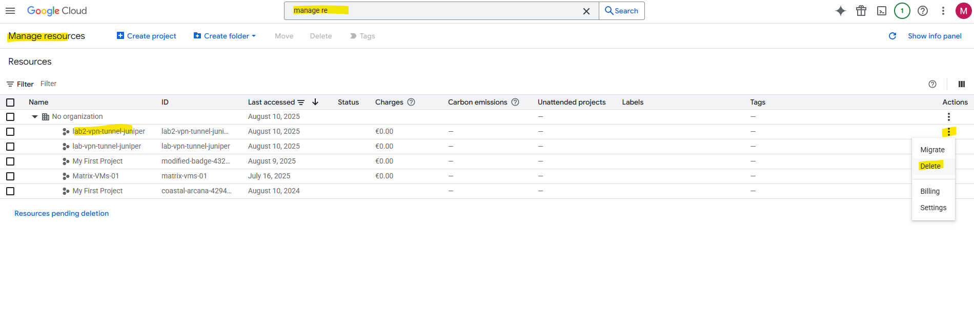
Under Manage resources we will see a list of our projects and can also delete them here.
So next we will create a new VPC network and virtual machine in this project we later connect through the VPN tunnel with our on-premise network.
In GCP, a VPC network is a global construct with regional subnets inside it.
In Azure, a VNet is regional, and cross-region networking is always a form of peering.
Creating VPC Network
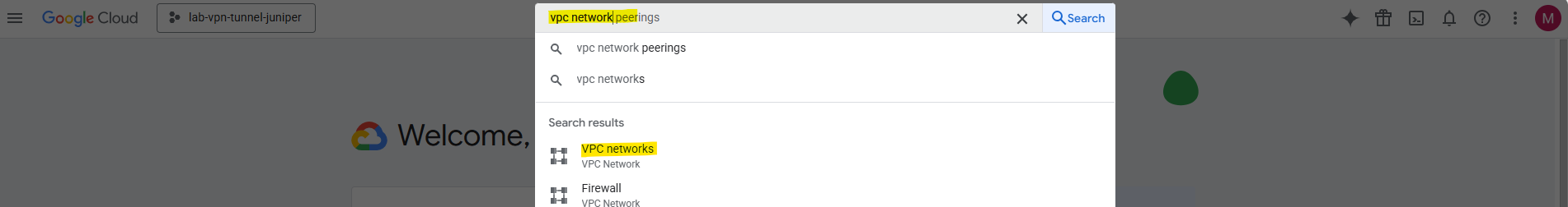
First we need to select the desired project we want to create our resources within. I will select here my previous newly created project named lab-vpn-tunnel-juniper.
Search for vpc network.
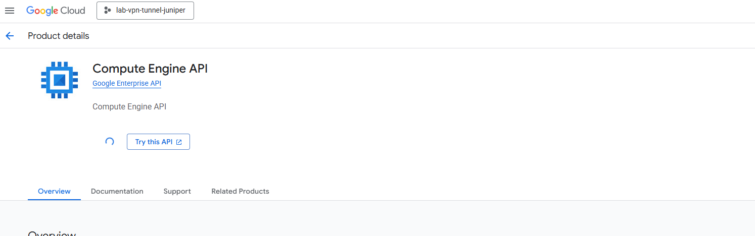
I first have to enable the Compute Engine API for this new project.
In a brand-new project, many services are disabled by default, including the Compute Engine API.
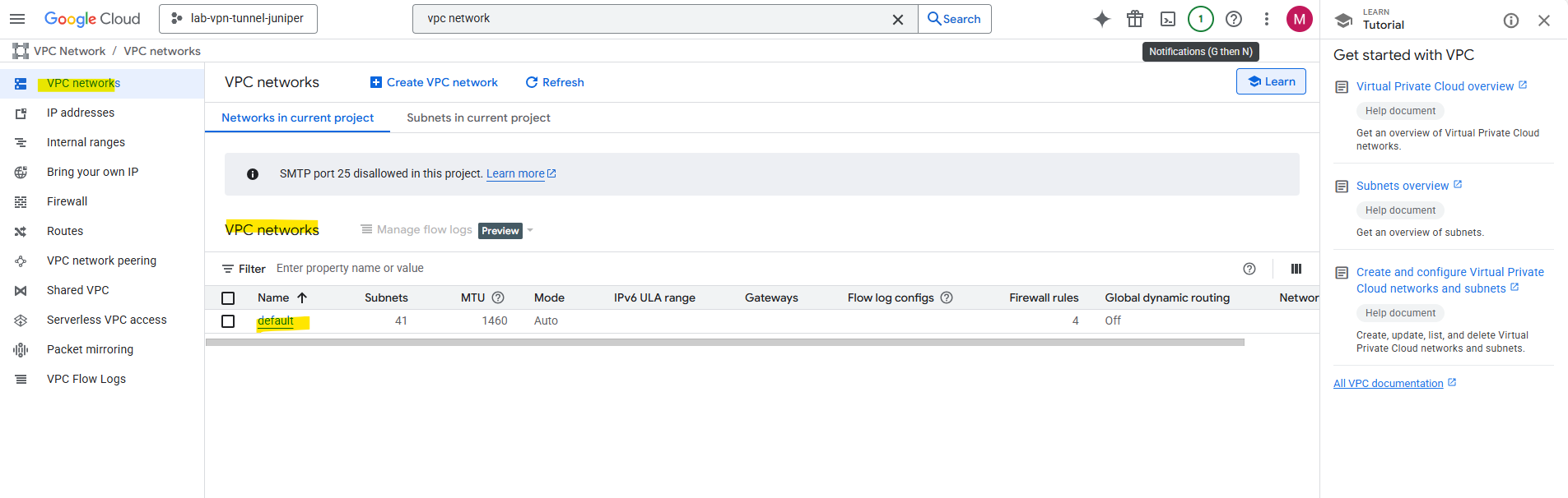
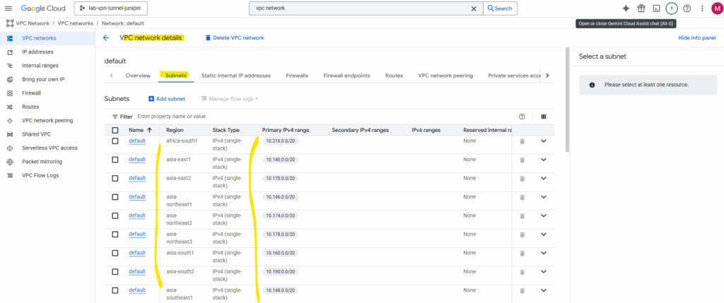
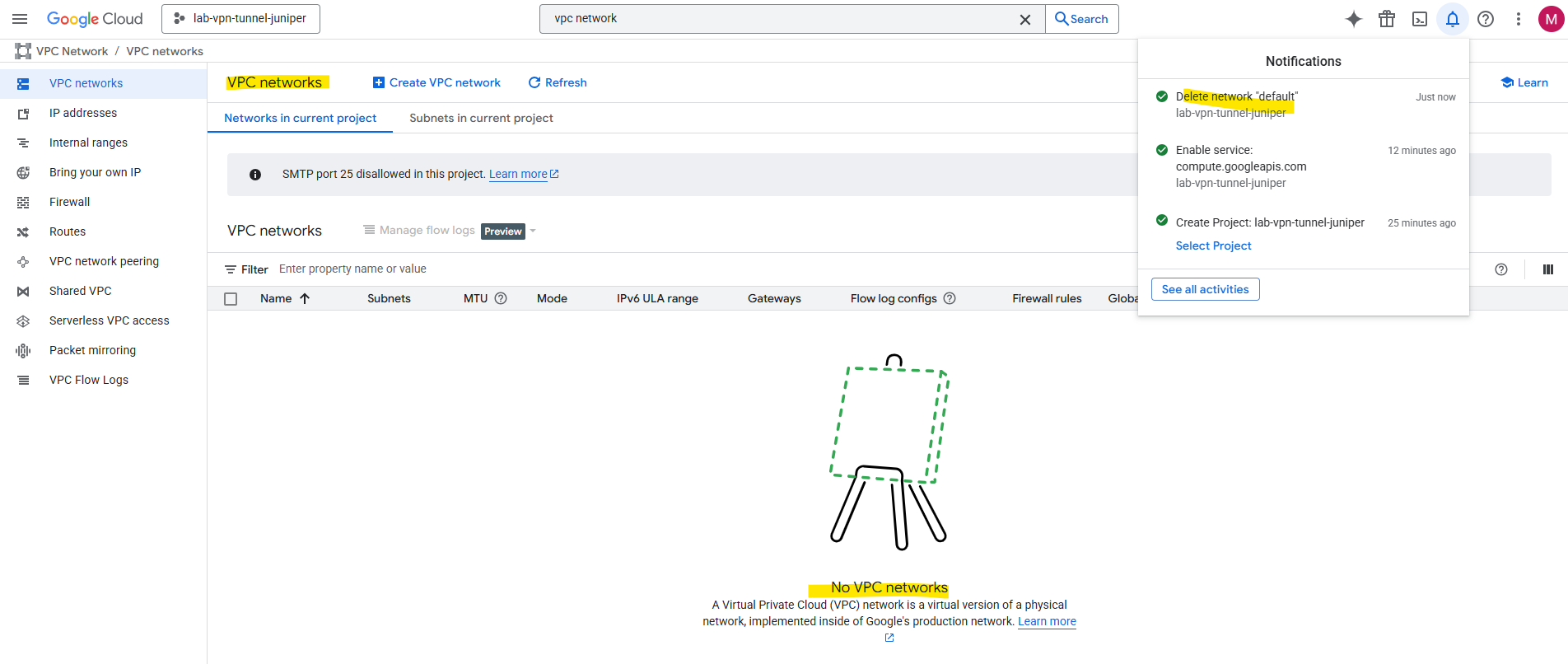
When you enable the Compute Engine API in a new project, here GCP will automatically create a default VPC network as shown below.
This default network includes again one subnet per region with default CIDRs and default firewall rules.
The default VPC is meant to be a “ready-to-use, global network” for people who are new to GCP and want to launch something without first learning networking.
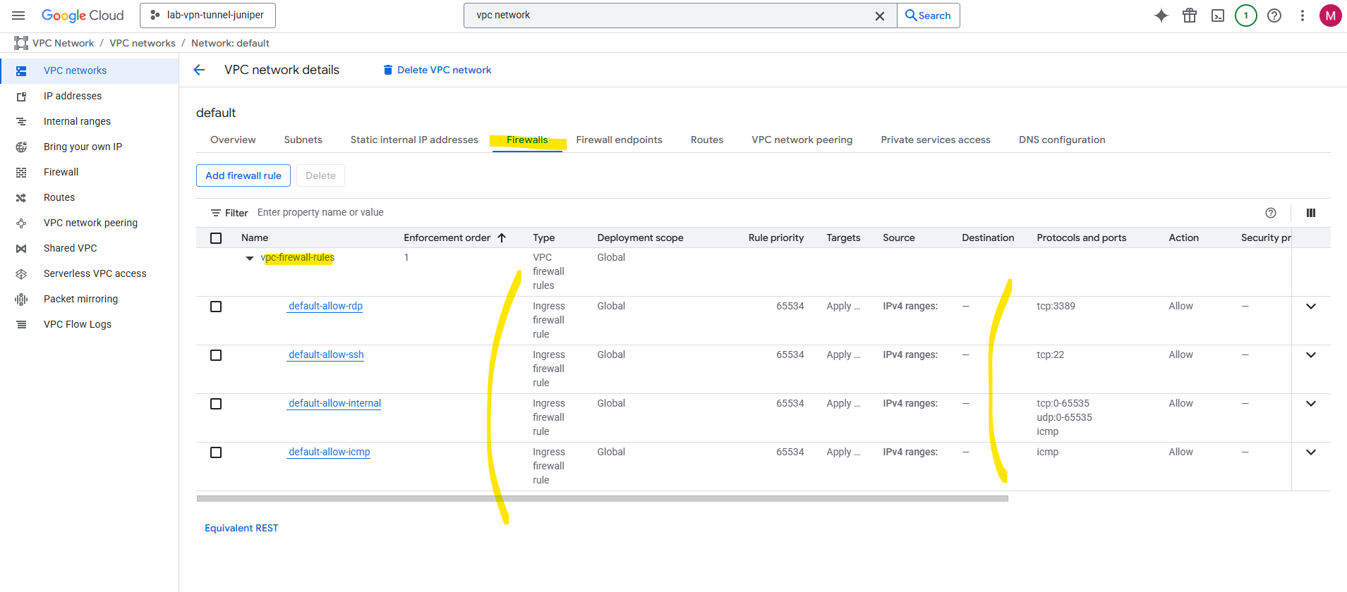
As mentioned the default VPC network will by default include one subnet per region with default CIDRs and default firewall rules.
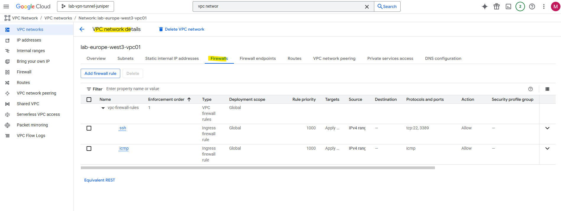
The default firewall rules.
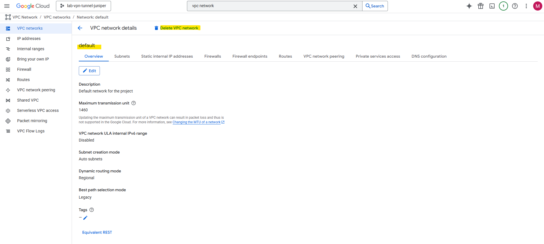
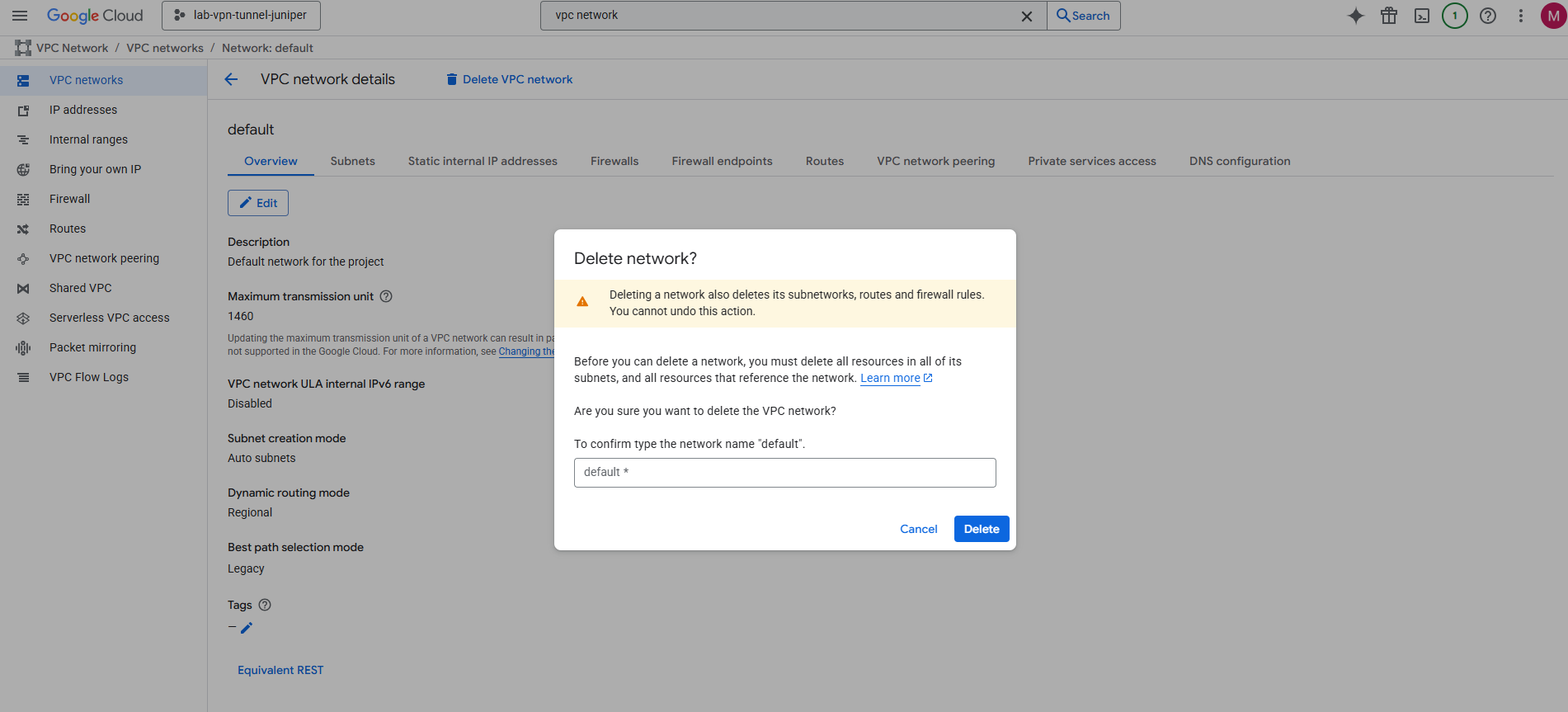
I will first delete this default VPC network. On the details page click on Delete VPC network.
Confirm the deletion.
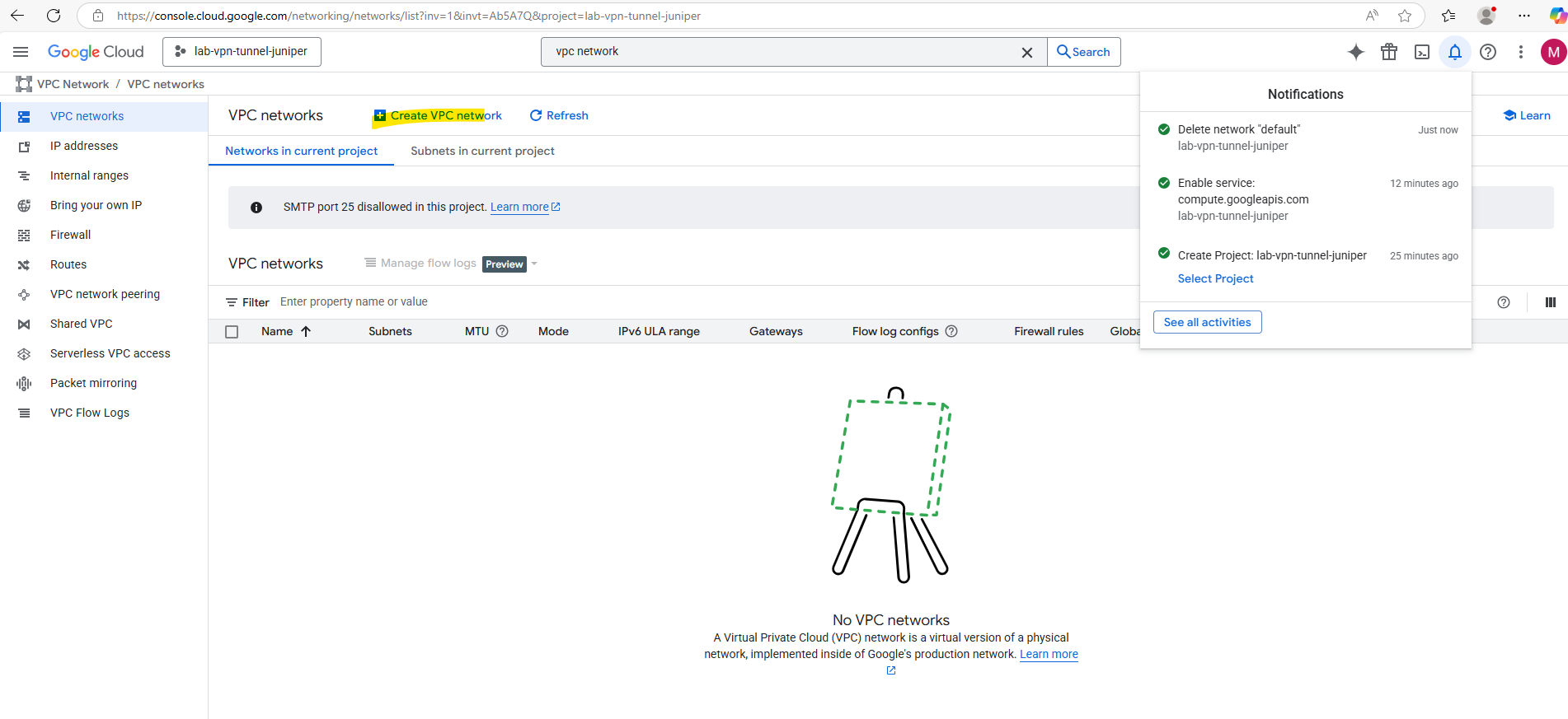
Next I will create a new VPC network we will use for the virtual machine (our workload in GCP) and VPN tunnel.
Click on Create VPN network.
Enter a name for the network and first new subnet.
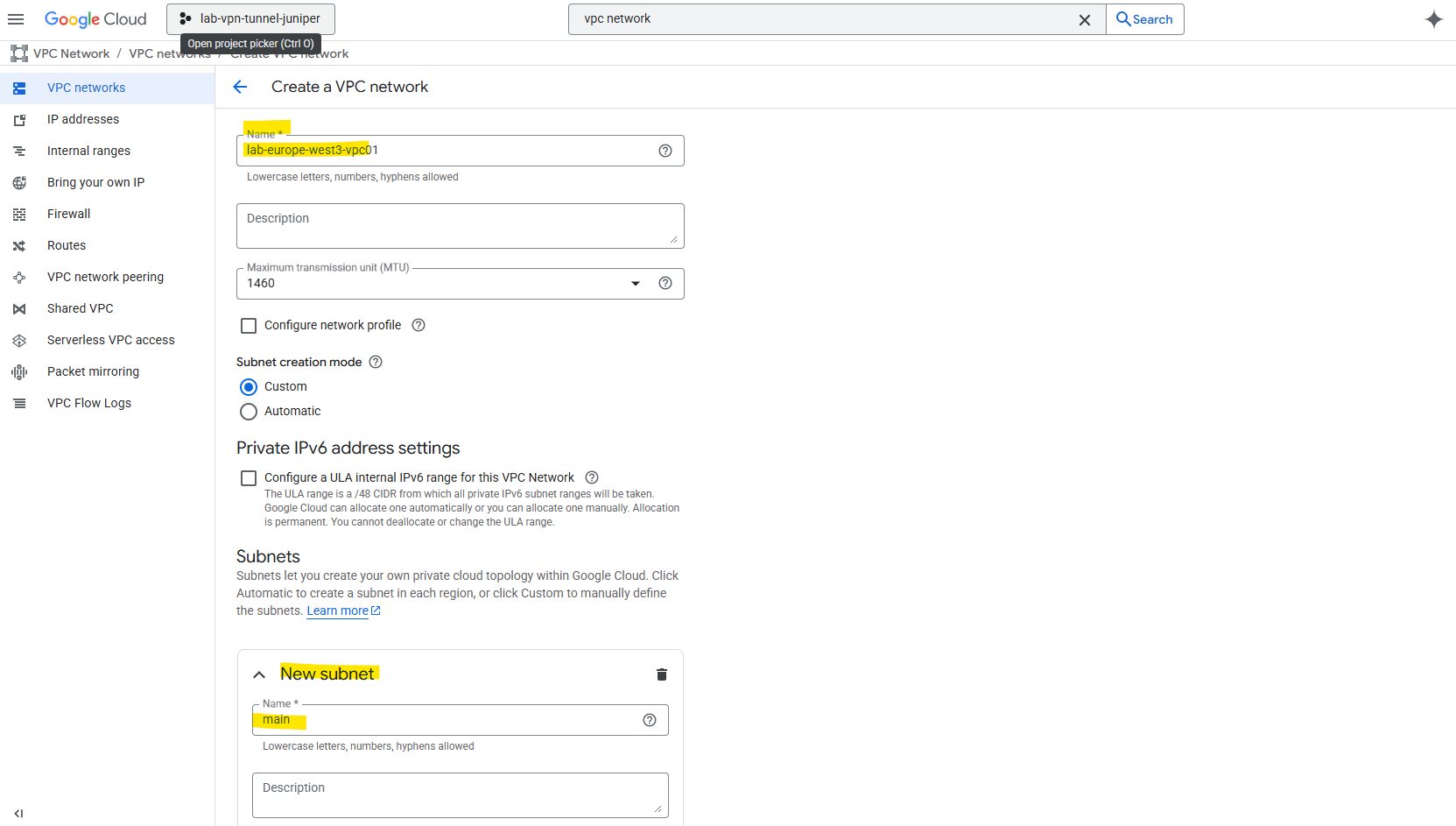
Select the desired region for the first new subnet, as mentioned, the VPC network itself has no specific region and is globally.
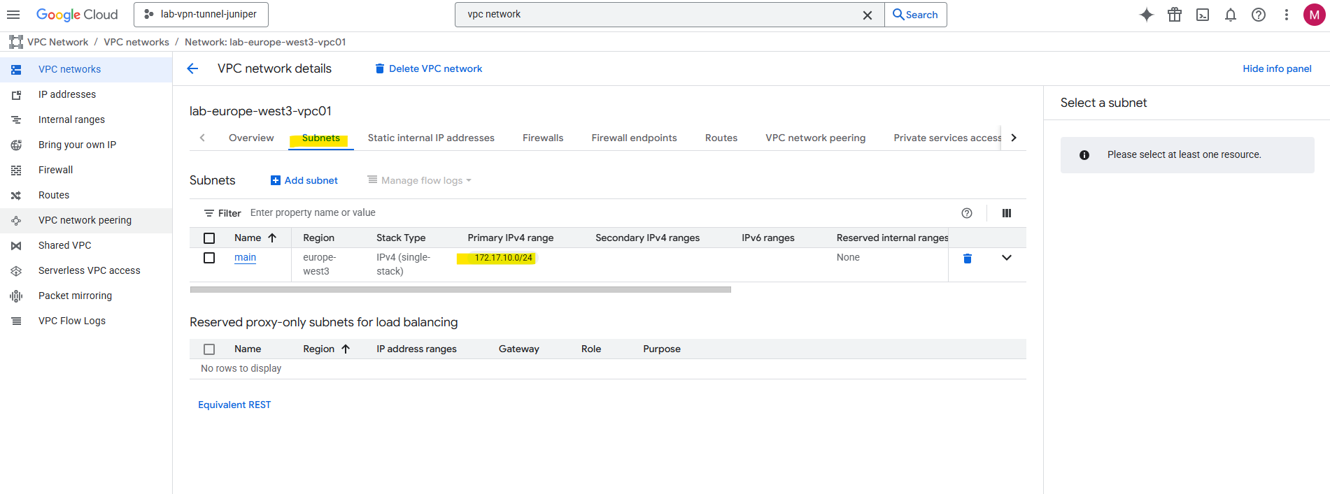
Also define and enter an IPv4 range. I will use here 172.17.10.0/24. If wanted we can also create here already further subnets or adding them later.
A VPC network itself has no CIDR, it’s just a global container for subnets, routes, and firewall rules. That’s one big conceptual shifts when coming from Azure.
Address space is defined only at the subnet level.
Subnets in the same VPC can have completely different CIDRs, as long as they don’t overlap. You can even add/remove subnets in different regions independently without touching the rest of the network.
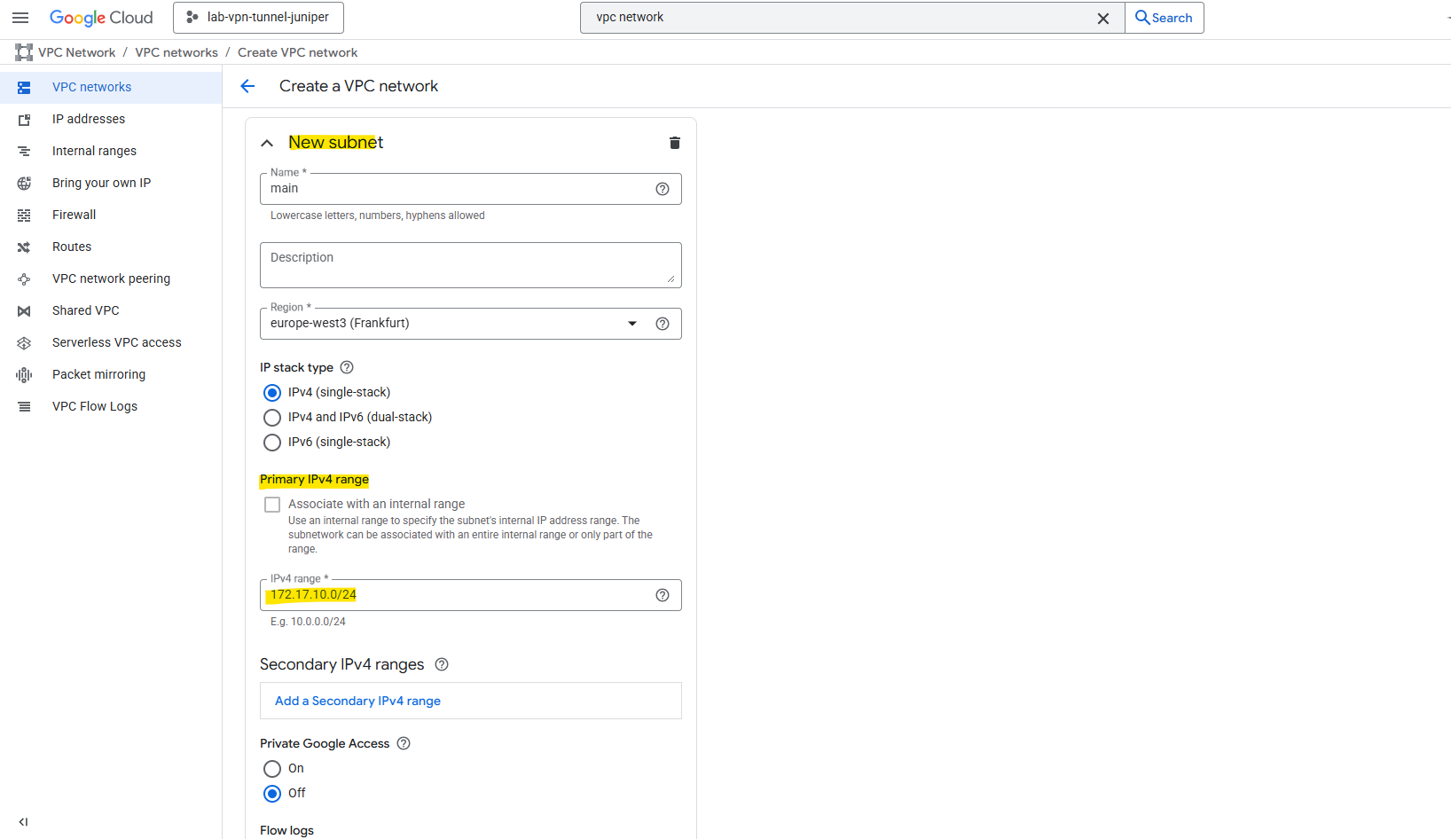
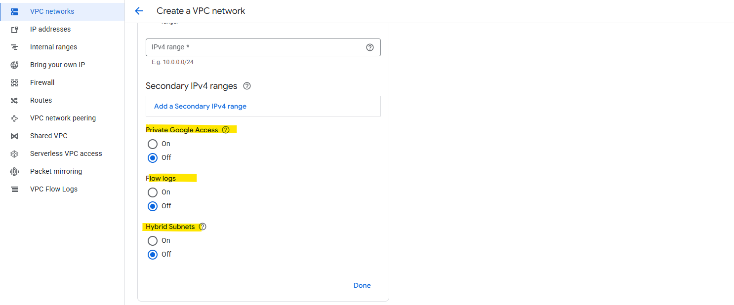
We can also set the following three options for our new subnet. I will enable here Private Google Access.
Private Google Access in GCP is a setting you can enable per subnet that allows VMs without an external IP address to reach Google APIs and services over Google’s private network instead of the public internet.
If Private Google Access = ON, that VM can still reach things like Cloud Storage (storage.googleapis.com), BigQuery, Cloud Pub/Sub, Other Google-managed APIs. The traffic stays inside Google’s internal backbone, it does not go out over the public internet.
You don’t need Cloud NAT or an internet gateway for this access.
VPC Flow Logs are like Azure’s NSG Flow Logs, they record network connection metadata for traffic going through a subnet.
About Hybrid Subnets you will find here more https://cloud.google.com/vpc/docs/hybrid-subnets.
The firewall rules I will leave so far on its default settings, we may need to add later some more rules to allow specific traffic between on-premise and GCP workloads.
We do not need to allow here traffic to establish the tunnel itself like esp, BGP TCP 179, UDP 500 or 4500.
In GCP the Cloud VPN gateway and Cloud Router sits outside our VPC network, and Google automatically allows the VPN control plane traffic (IKE, ESP, BGP) between the VPN gateway and our on-premises peer.
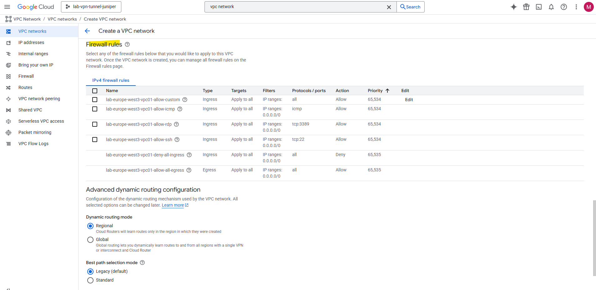
Click on Create.
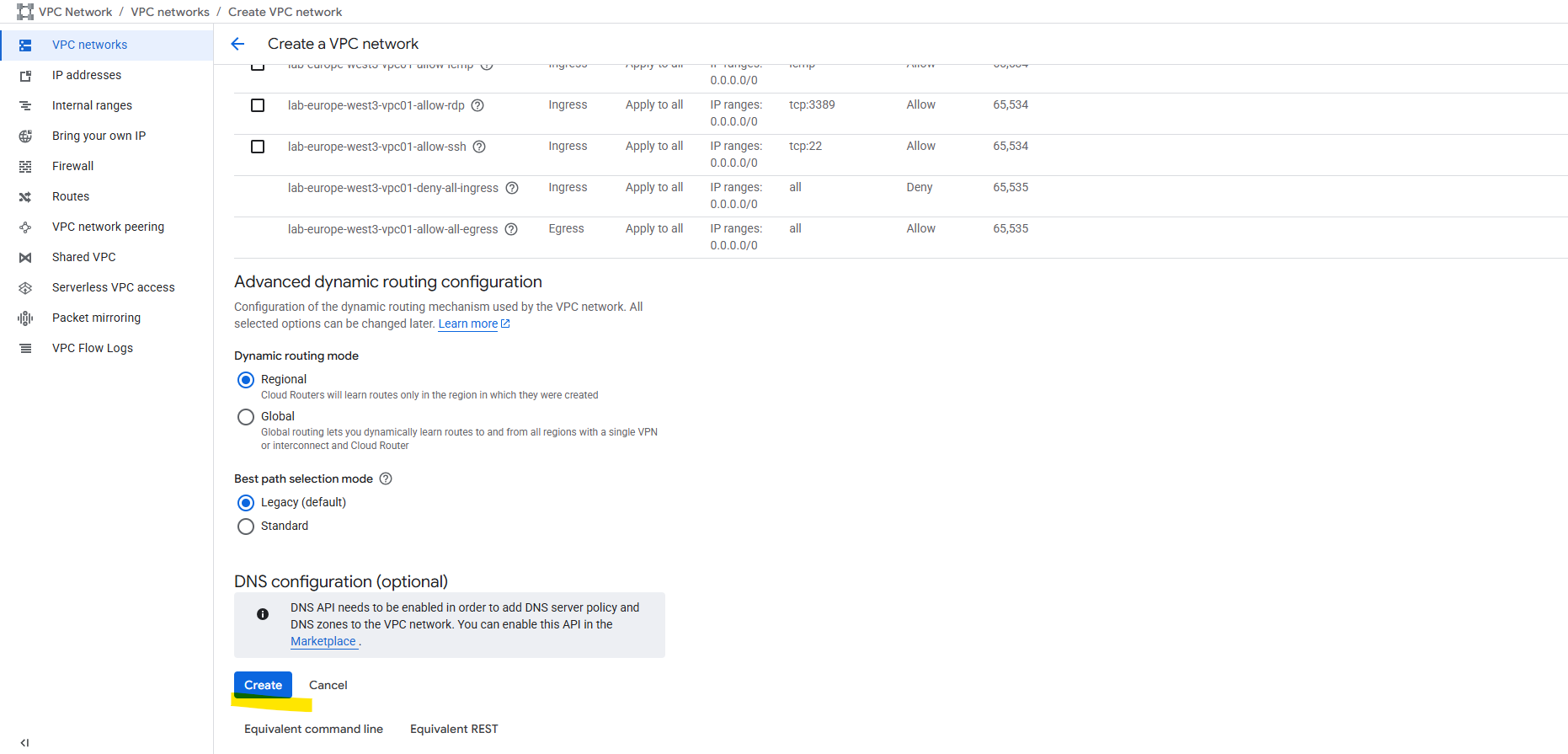
Finally our new custom VPC network and its subnet is created.
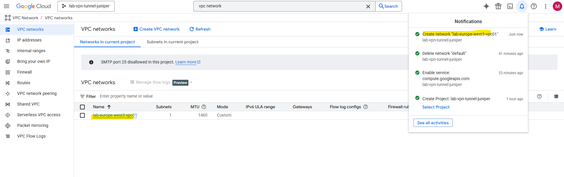
We also need to add some firewall rules to allow inbound (ingress) traffic.
Create Virtual Machine Instance
For brevity, this post skips the VM creation process. I will show this in detail in one of my next posts soon.
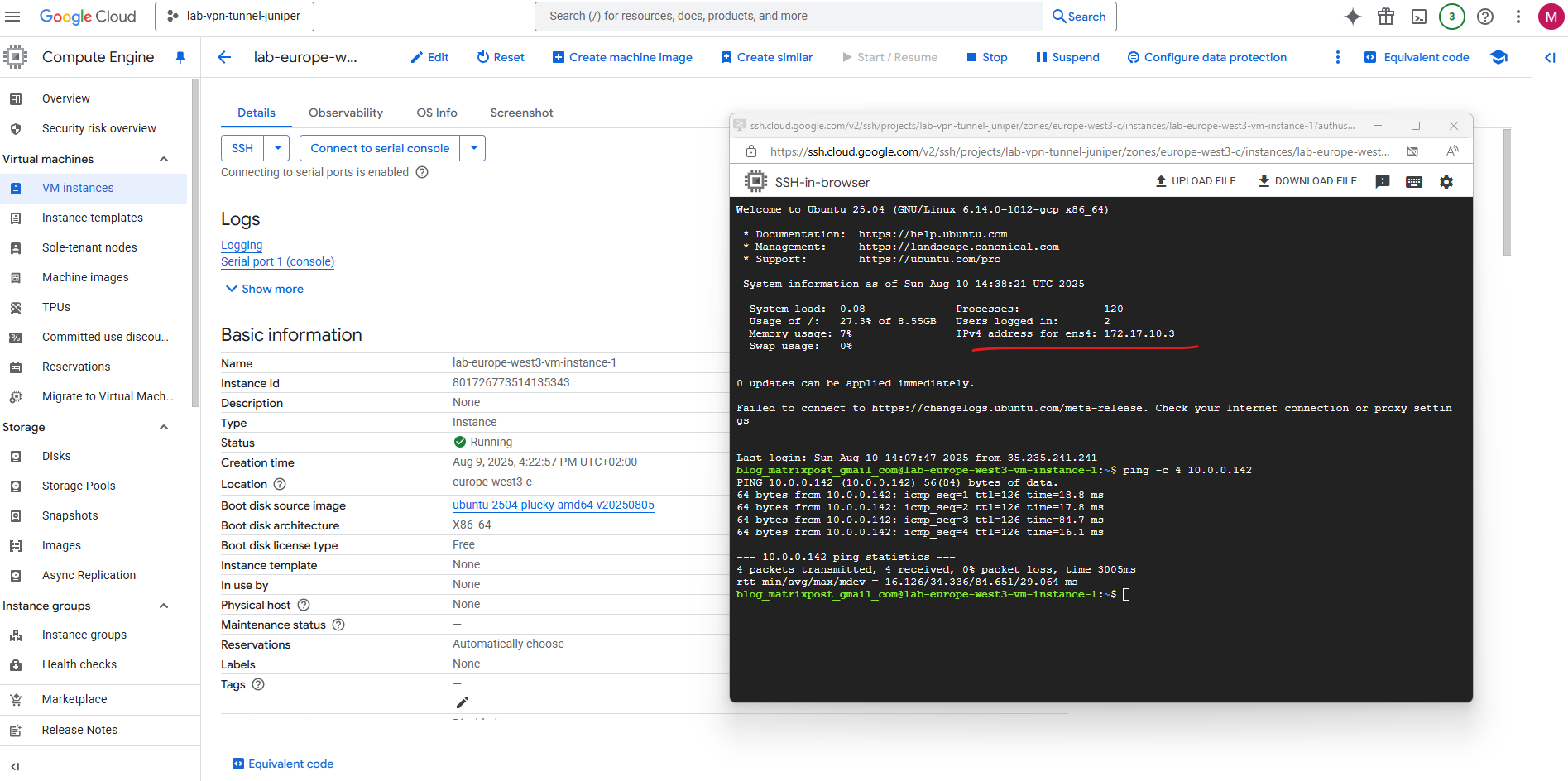
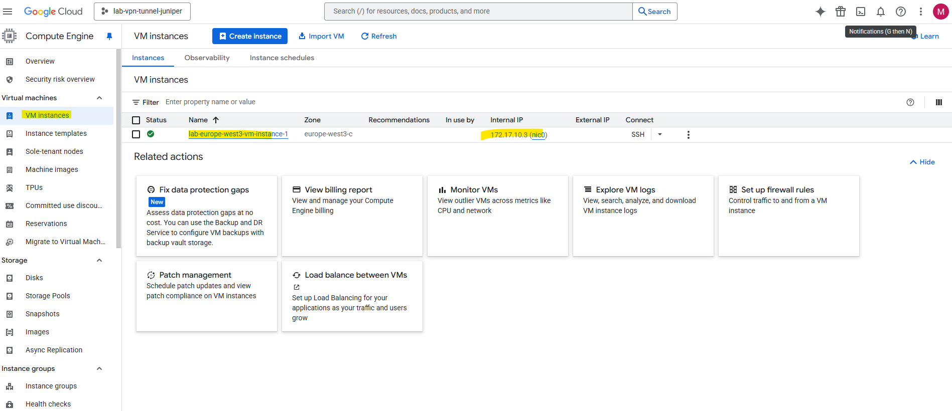
To test if traffic is routed between GCP and on-premise, I will use the following virtual machine with its automatically assigned private IP address 172.17.10.3 by the previously created VPC network and subnet.
Set up the Tunnel in GCP
To set up the VPN tunnel in GCP we first need to create a HA VPN gateway.
In GCP, the HA VPN gateway is Google Cloud’s fully managed, high-availability VPN endpoint for site-to-site IPsec connections.
Think of it as the GCP-side VPN appliance you connect your on-prem firewall/router to except it’s redundant, cloud-managed, and natively integrated into Google’s VPC networking.
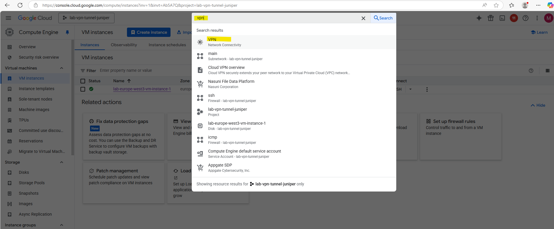
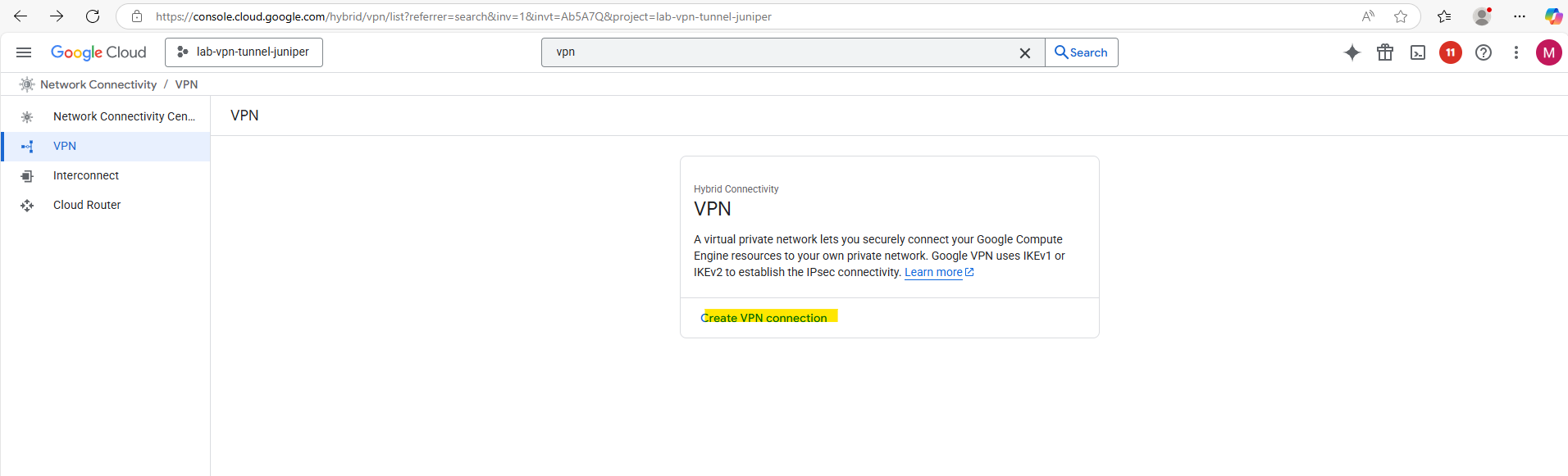
Search for vpn and select below VPN – Network Connectivity.
Click on Create VPN connection.
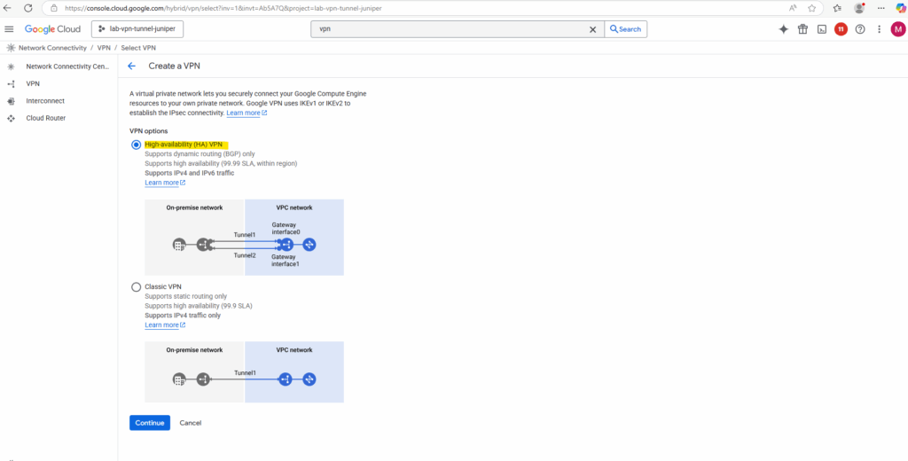
Select High-availability (HA) VPN.
If your device does not support BGP, you should use Classic VPN which still supports static routing as mentioned to the beginning.
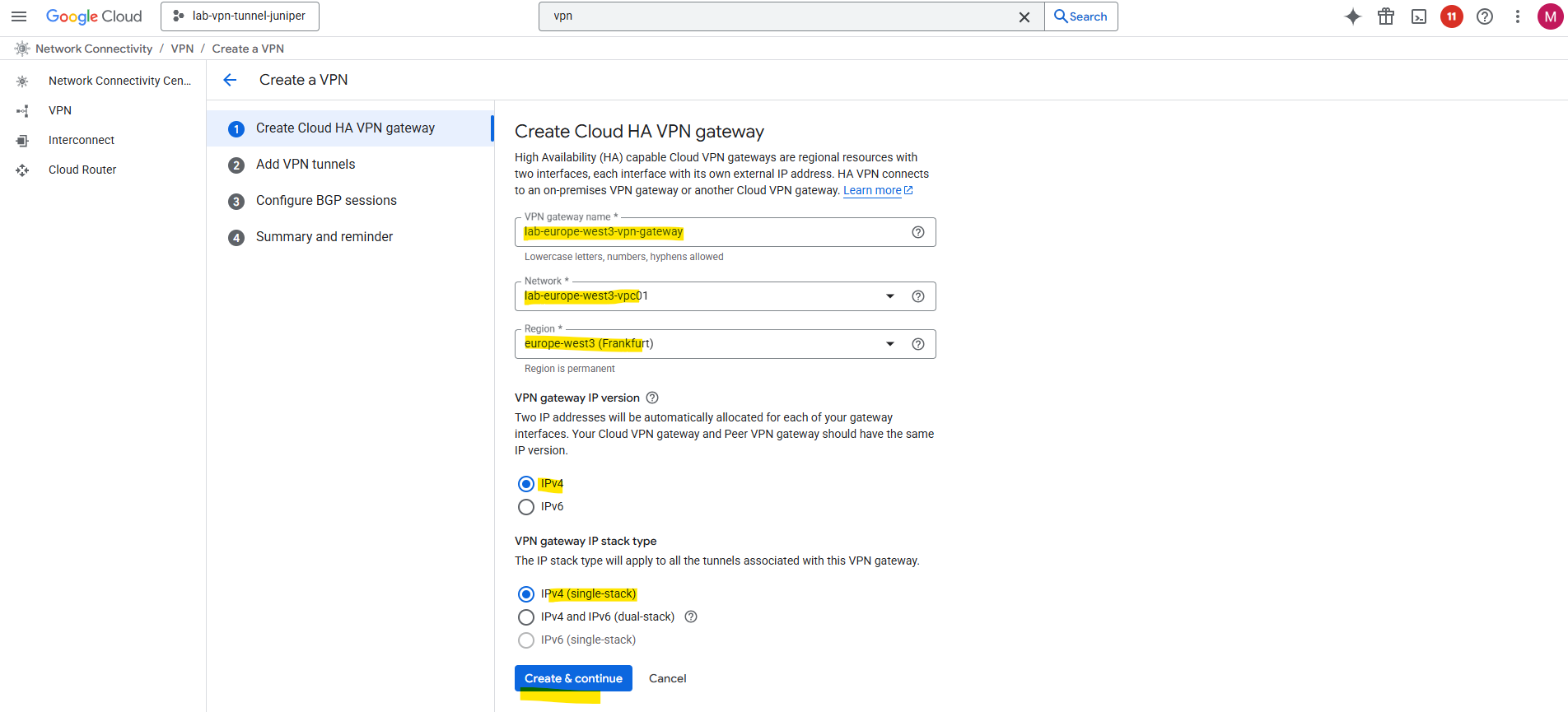
Enter a name for the VPN gateway, the VPC network in which it will be deployed and its region.
Click on Create & continue.
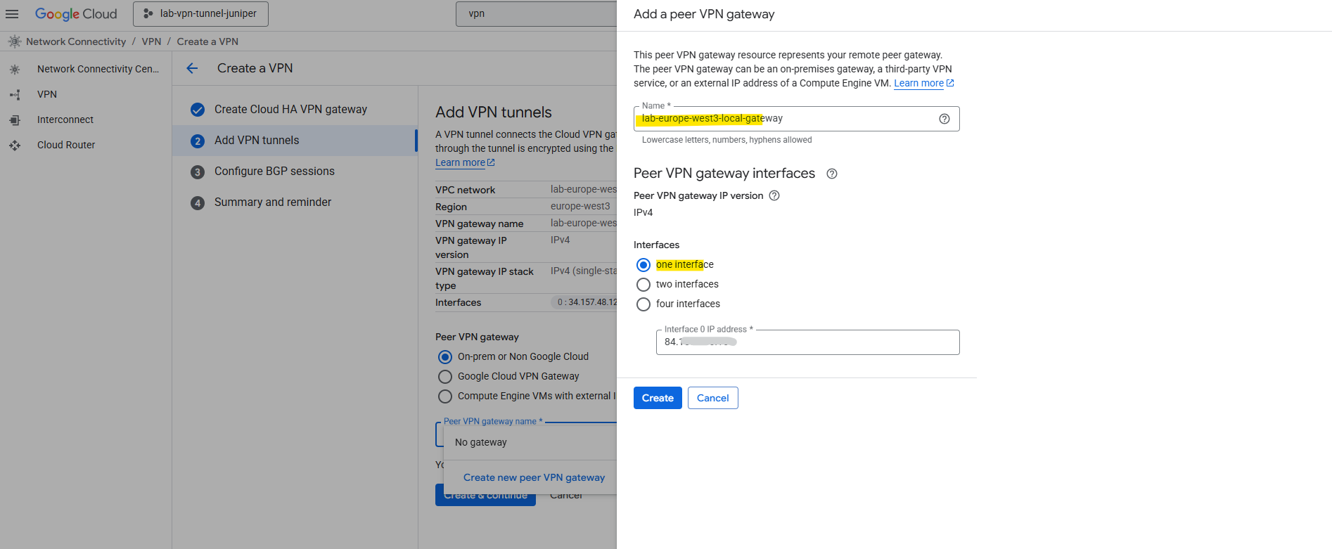
On the Add VPN tunnels tab create a new peer VPN gateway. This will represent our local on-premise gateway (VPN device), in my case here the Juniper vSRX3 appliance.
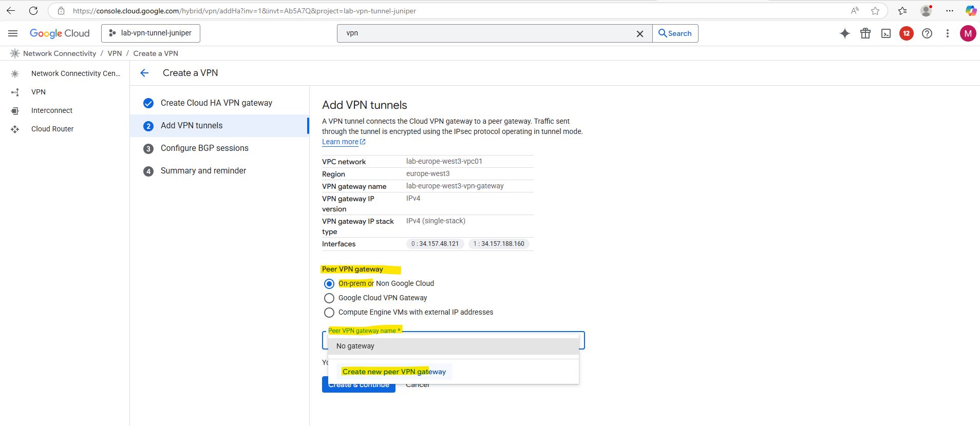
Enter the public IP address of your on-premise VPN device and click on Create. I will just have one interface here for my lab environment and therefore won’t provide high availability.
One of the annoying limitations with GCP’s HA VPN is that it won’t support here FQDNs and it is required to use the public IP address for, Azure’s VPN gateway in contrast will let you put an FQDN for the remote peer, so dynamic DNS works fine if your on-prem IP changes.
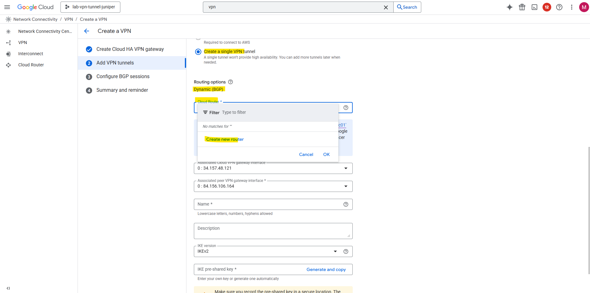
As mentioned to the beginning, HA VPN requires BGP, therefore we need to create a cloud router in GCP which finally handles BGP functionality, this is not the VPN gateway (VPN device) in GCP.
Dynamic (BGP) routing provides the easiest to configure and most resilient IPsec VPN configuration.
Because the routing must fail over automatically between tunnels and interfaces, GCP requires BGP, static routes can’t provide the same automatic failover mechanism.
If your device does not support BGP, you should use Classic VPN which still supports static routing.
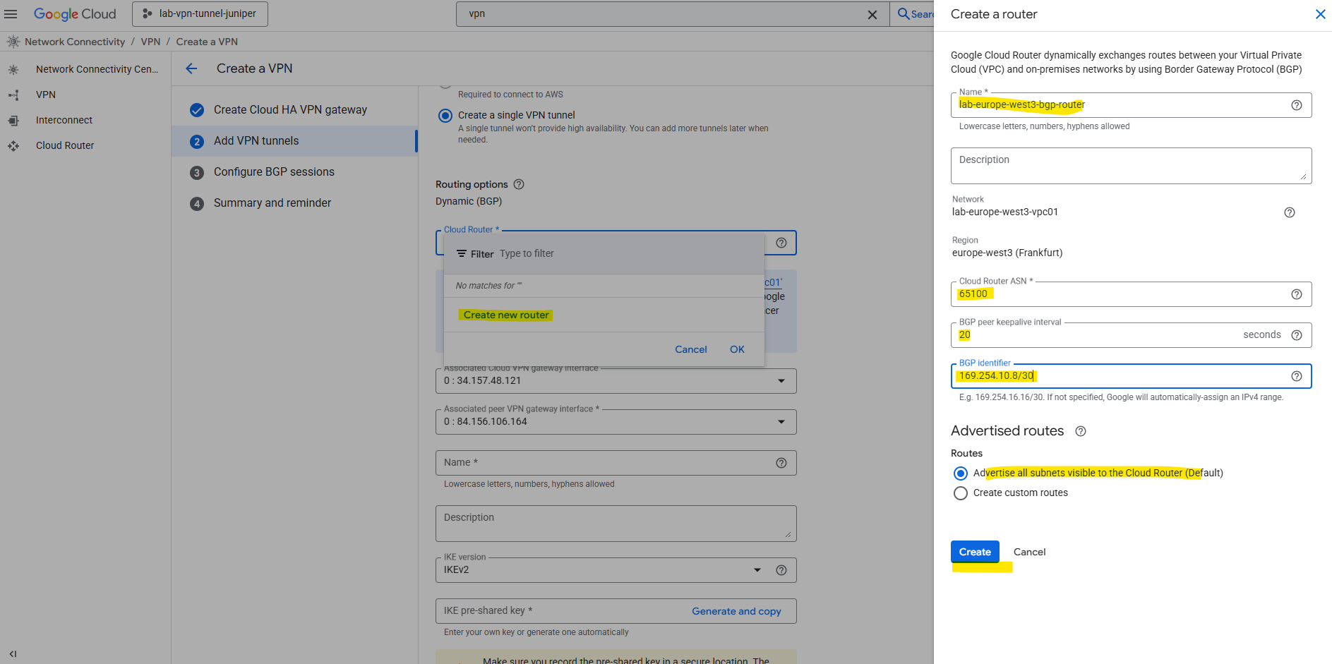
In GCP we can pick for the BGP identifier any unused IPv4 address in 169.254.0.0/16, as long as it’s at least a /30 range for the point-to-point link.
So I will use here 169.254.10.8/30 but finally we can also leave it blank and GCP will assign it automatically.
The BGP Identifier is essentially the router’s unique ID within a BGP session. It’s a 32-bit value, usually expressed as an IPv4 address, and it must be unique among all BGP speakers in the same AS. It’s used inside BGP messages for loop prevention and to distinguish peers, it’s not used for routing traffic.
So this is not the /30 subnet used for the IPSec phase 2 tunnel interfaces on both sides. They will be automatically assigned and we will see aftter creating this cloud router.
Below we can see the public IPv4 address from the Cloud VPN gateway’s interface and my on-premise Juniper (peer VPN gateway interface).
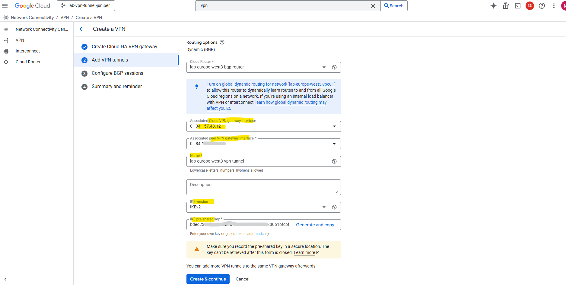
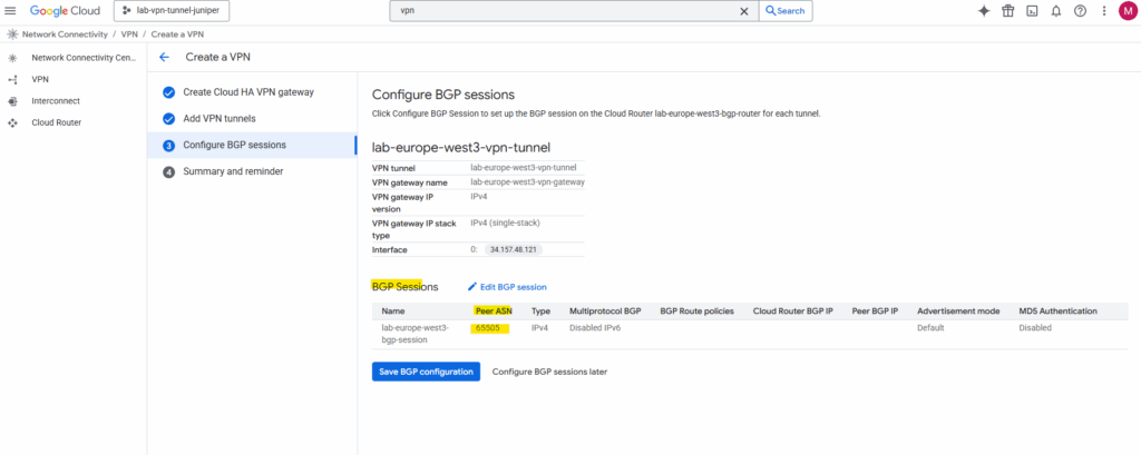
Next we need to configure BGP on the cloud router, so click on Configure BGP session for …
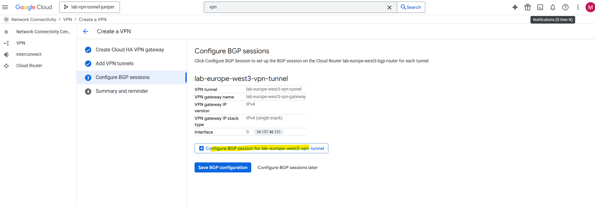
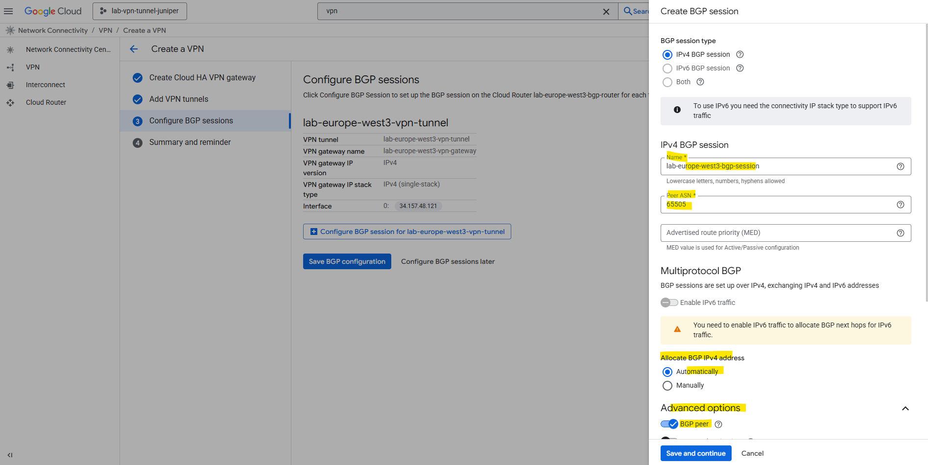
Enter a name for the BGP session, the peer ASN (our on-premise VPN device).
Under Advertised routes we can control which routes will be advertised to our on-premise peer (Juniper appliance) by checking Create custom routes. I will leave the default settings.
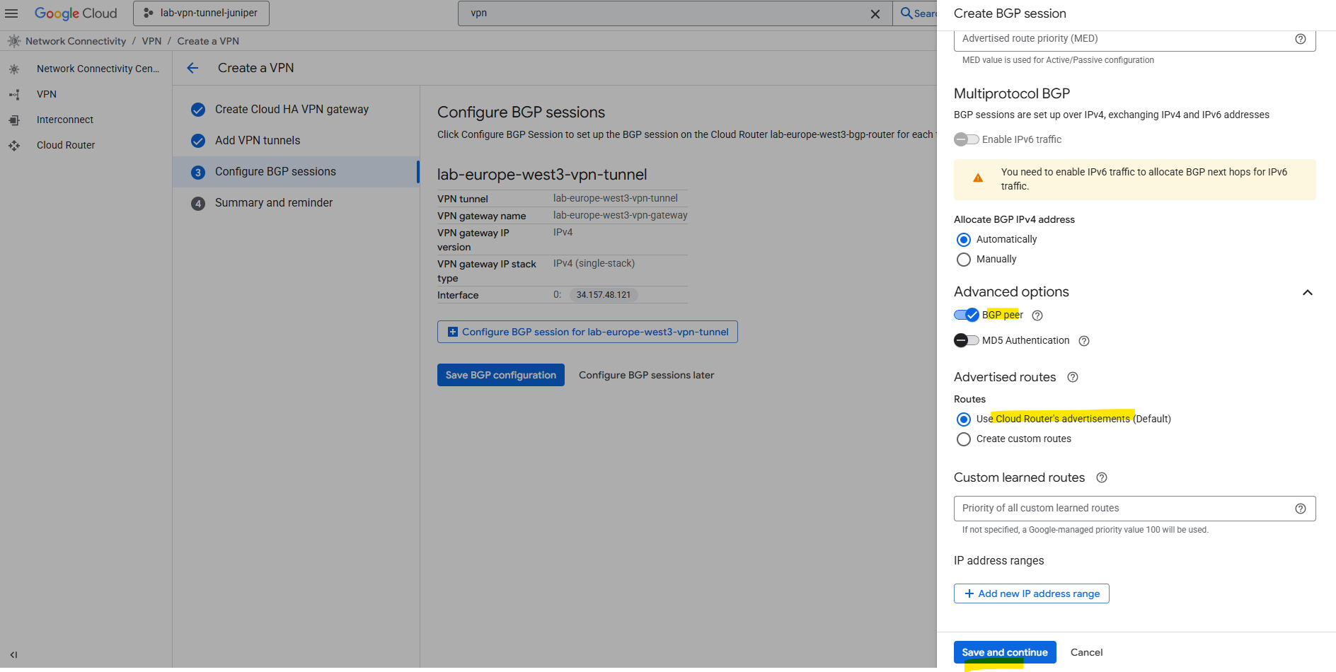
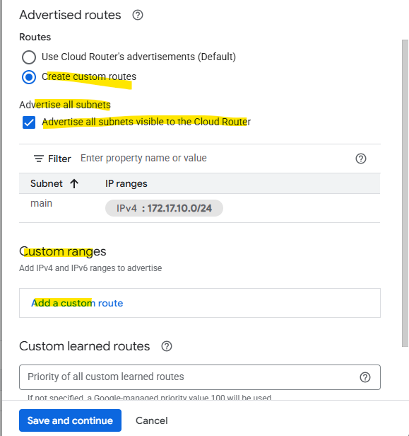
To add custom routes we need to select below “Create custom routes”.
When checking Advertise all subnets visible to the Cloud Router it means ==> The routes that are all prefixes that the Cloud Router currently knows about within its scope, which depends on its associated VPC network, its region and the routing mode (regional or global dynamic routing).
The screenshot is from a different deployment.
Which routes finally will be advertised to the BGP peer (on-prem here) we will see on the Cloud Router tab below. We can also switch the route direction to see the learned routes from our BGP peer.
The screenshot is also from a different deployment.
Finally save the BGP configuration.
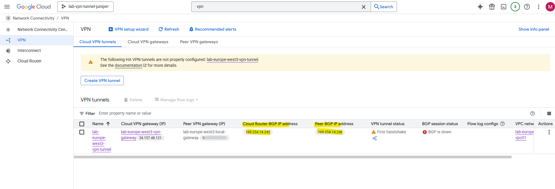
Finally click on OK, because we haven’t set up so far the on-premise VPN device, the BGP session in GCP of course is currently down.
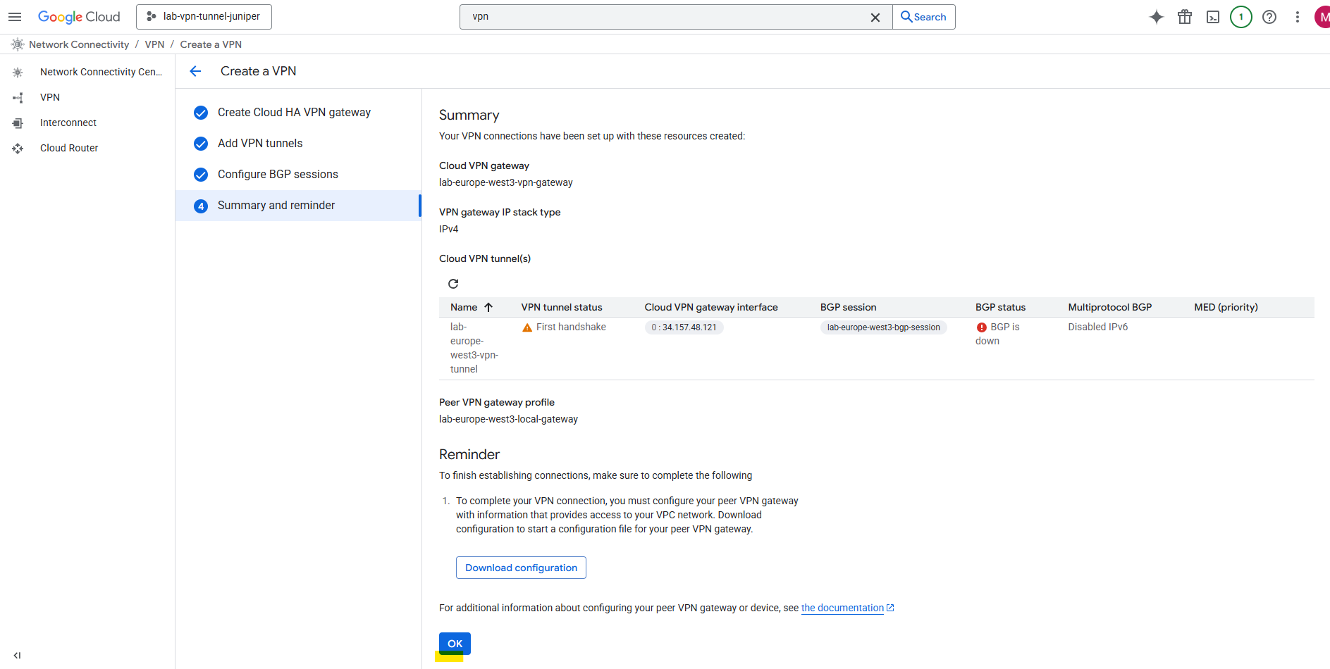
Also the tunnel itself of course currently is down until we configure our on-premise VPN device accordingly.
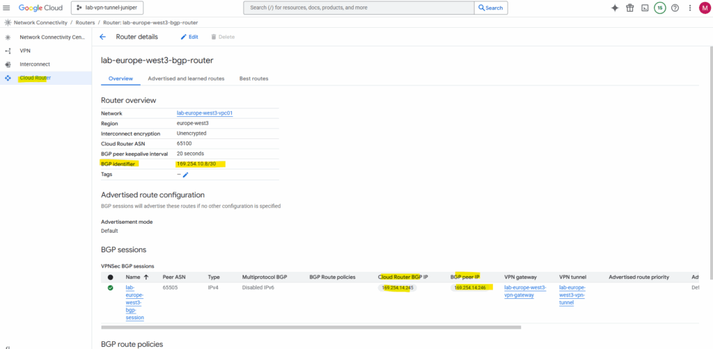
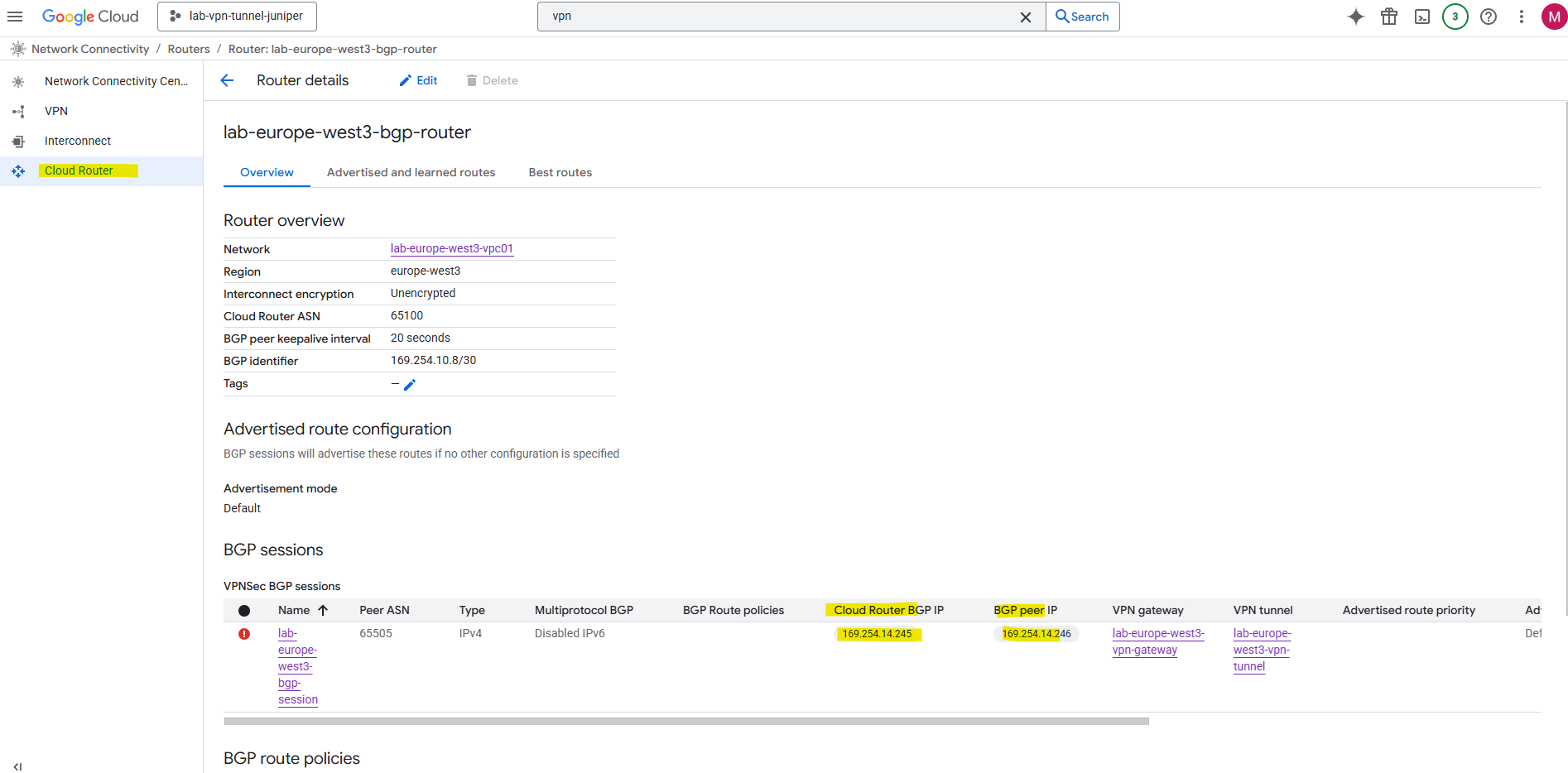
Below we will see the previously mentioned and by GCP automatially assigned IP addresses for the IPSec phase 2 tunnel interfaces in GCP and for our on-premise VPN device we later need to configure on Junipers tunnel interface.
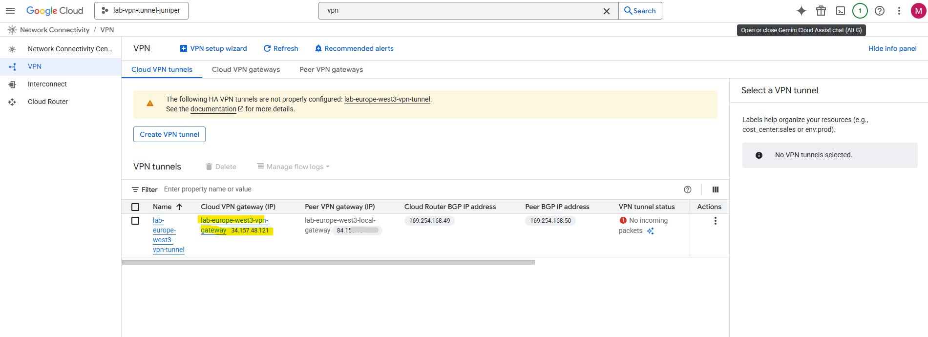
The BGP identifier we can determine directly on the cloud router and as mentioned is different from the IPsec phase 2 tunnel interfaces used for routing the subnets between both sides and also for the BGP session itself.
Set up the Tunnel on Juniper by using the CLI
First of all GCP’s HA VPN doesn’t make prompt us to pick phase 1/2 proposals, it just auto-negotiates with whatever our peer proposes, as long as they’re in Google’s supported cipher list.
You will find here all supported ciphers by GCP https://cloud.google.com/network-connectivity/docs/vpn/concepts/supported-ike-ciphers.
On the Juniper vSRX we still need to define proposals, so just pick a set that GCP definitely accepts.
I will use here the same I was already using to set up an tunnel with Azure and shown in my previous post here.
- Phase 1 IKEv2 ✔ (
aes-256-cbc,sha-256,dh-group14, lifetime 28800s) - Phase 2 IPsec ESP ✔ (
aes-256-cbc+hmac-sha-256-128, lifetime 28800s) - PFS not explicitly set the policy (fine; optional)
I will show below the set up in Juniper vSRX just by using the CLI, about how to set up a tunnel by using the Web UI, you can read my post about how to set up the tunnel with Azure shown here.
IKE Phase 1 (IKEv2)
We can commit just at the end and don’t need to do this after each section.
set security ike proposal GCP_IKE_PROPOSAL authentication-method pre-shared-keys
set security ike proposal GCP_IKE_PROPOSAL dh-group group14
set security ike proposal GCP_IKE_PROPOSAL authentication-algorithm sha-256
set security ike proposal GCP_IKE_PROPOSAL encryption-algorithm aes-256-cbc
set security ike proposal GCP_IKE_PROPOSAL lifetime-seconds 28800

set security ike policy GCP_IKE_POLICY proposals GCP_IKE_PROPOSAL
set security ike policy GCP_IKE_POLICY reauth-frequency 0

# adjust to your pre-shared key
set security ike policy GCP_IKE_POLICY pre-shared-key ascii-text "<your_psk>"

set security ike gateway GCP_IKE_GATEWAY ike-policy GCP_IKE_POLICY
set security ike gateway GCP_IKE_GATEWAY address <GCP_Public_IP>
set security ike gateway GCP_IKE_GATEWAY no-nat-traversal   ## Important! GCP VPN Gateway sits not behind NAT

# for the local-identiy of Juniper I will use my dynDNS FQDN, usually you will use here the static public IP of your on-premise VPN device
set security ike gateway GCP_IKE_GATEWAY local-identity hostname matrixpost.ddns.net

set security ike gateway GCP_IKE_GATEWAY remote-identity inet <GCP_Public_IP>

# My external external-interface ge-0/0/1.0 sits behind a NAT router which supports NAT-T, usually you would assign here your external public IP address. In my lab environment I will have a private IP address assigned for the perimeter network.
set security ike gateway GCP_IKE_GATEWAY external-interface ge-0/0/1.0

set security ike gateway GCP_IKE_GATEWAY version v2-only
IPSec Phase 2
set security ipsec proposal GCP_IPSEC_PROPOSAL protocol esp
set security ipsec proposal GCP_IPSEC_PROPOSAL authentication-algorithm hmac-sha-256-128
set security ipsec proposal GCP_IPSEC_PROPOSAL encryption-algorithm aes-256-cbc
set security ipsec proposal GCP_IPSEC_PROPOSAL lifetime-seconds 28800

set security ipsec policy GCP_IPSEC_POLICY proposals GCP_IPSEC_PROPOSAL

set security ipsec vpn GCP_VPN bind-interface st0.0
set security ipsec vpn GCP_VPN ike gateway GCP_IKE_GATEWAY
set security ipsec vpn GCP_VPN ike ipsec-policy GCP_IPSEC_POLICY
set security ipsec vpn GCP_VPN establish-tunnels immediately
Interface & Routing
# adjust the VTI (virtual tunnel interface) to your environment in GCP.
set interfaces st0 unit 0 family inet address 169.254.14.246/30

# add a static routing for your GCP network
set routing-options static route 172.17.0.0/16 next-hop st0.0
The IP address we need to use above for the IPsec phase 2 tunnel (transit network + BGP session) we will find under the Cloud VPN tunnels in GCP. As mentioned further above, they will be assigned automatically by GCP.
In Azure in contrast the BGP peer IP address for a VPN gateway is automatically assigned from the GatewaySubnet range. Despite we have the option to also assign APIPA addresses, Azure supports BGP IP in the ranges 169.254.21.* and 169.254.22.*.
Or directly on the cloud router.
Security Zones
set security zones security-zone vpn interfaces st0.0
set security zones security-zone trust interfaces ge-0/0/0.0
set security zones security-zone untrust interfaces ge-0/0/1.0
set security zones security-zone untrust screen untrust-screen
Security Policies
# Trust → VPN
set security policies from-zone trust to-zone vpn policy trust-to-azure match source-address any
set security policies from-zone trust to-zone vpn policy trust-to-azure match destination-address any
set security policies from-zone trust to-zone vpn policy trust-to-azure match application any
set security policies from-zone trust to-zone vpn policy trust-to-azure then permit

# VPN → Trust
set security policies from-zone vpn to-zone trust policy azure-to-trust match source-address any
set security policies from-zone vpn to-zone trust policy azure-to-trust match destination-address any
set security policies from-zone vpn to-zone trust policy azure-to-trust match application any
set security policies from-zone vpn to-zone trust policy azure-to-trust then permit
Logging & Debugging (optional but useful)
set system syslog file ike-log any any
set system syslog file ike-log match invalid
set security ike traceoptions file ike-debug
set security ike traceoptions file size 1m
set security ike traceoptions file files 5
set security ike traceoptions flag all
As already mentioned, finally we need to commit our new configuration.
root@junos-vsrx3# commit
Special Notes
Firewall policies are wide open between zones. You may want to restrict these for production.
Enable and Configure BGP on Juniper vSRX3
Set BGP group and peer
The GCP ASN we will find under VPN Network Connectivity -> Cloud Router. Here we can see that the GCP ASN is 65100.
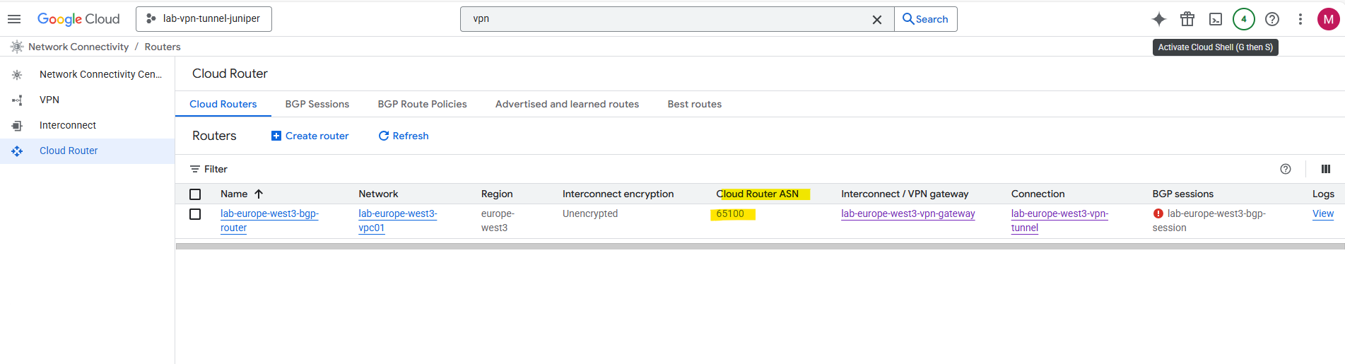
We set this ASN previously when creating the Google Cloud Router.
set protocols bgp group GCP type external
set protocols bgp group GCP peer-as 65100                     # GCP ASN
set protocols bgp group GCP neighbor 169.254.14.245              # GCP BGP peer IP
Define your local ASN
set routing-options autonomous-system 65505 # Your ASN
Enable BGP on st0.0 tunnel interface
set protocols bgp group GCP local-address 169.254.14.246 # Juniper st0.0 IP second IP we added
Create a Export Policy
The export policy in Juniper BGP configuration defines which routes your device advertises to its BGP peers, in this case, Azure.
term 1 from protocol [ static direct ] ==> Matches routes learned via static or direct means. These are your local networks/subnets (e.g., LANs, loopbacks, default routes, etc.)
term 1 then accept ==> Advertises all matched routes (static and direct) to Azure
term 2 then reject ==> A fallback: reject any other routes that don’t match the above (like dynamic/BGP-learned routes from other neighbors)
set policy-options policy-statement EXPORT-TO-GCP term 1 from protocol [ static direct ]
set policy-options policy-statement EXPORT-TO-GCP term 1 then accept
set policy-options policy-statement EXPORT-TO-GCP term 2 then reject

# Apply the policy to the BGP Group
set protocols bgp group GCP export EXPORT-TO-GCP
And finally commit the configuration.
commit
We do not need an import policy on Juniper to accept GCP’s advertised routes, by default JunOS accepts all BGP routes unless you configure an explicit import policy to filter them.
When you might need an import policy, filter or restrict prefixes received from GCP (e.g., only accept 172.17.0.0/16 and reject others)
set policy-options policy-statement IMPORT-FROM-GCP term 1 from route-filter 172.17.0.0/16 exact
set policy-options policy-statement IMPORT-FROM-GCP term 1 then accept
set policy-options policy-statement IMPORT-FROM-GCP term 2 then reject
set protocols bgp group GCP import IMPORT-FROM-GCP
Verify BGP is working
We can use the Google Cloud Console and here under Cloud VPN tunnels to check the state of the BGP session or the Google Cloud SDK (gcloud).
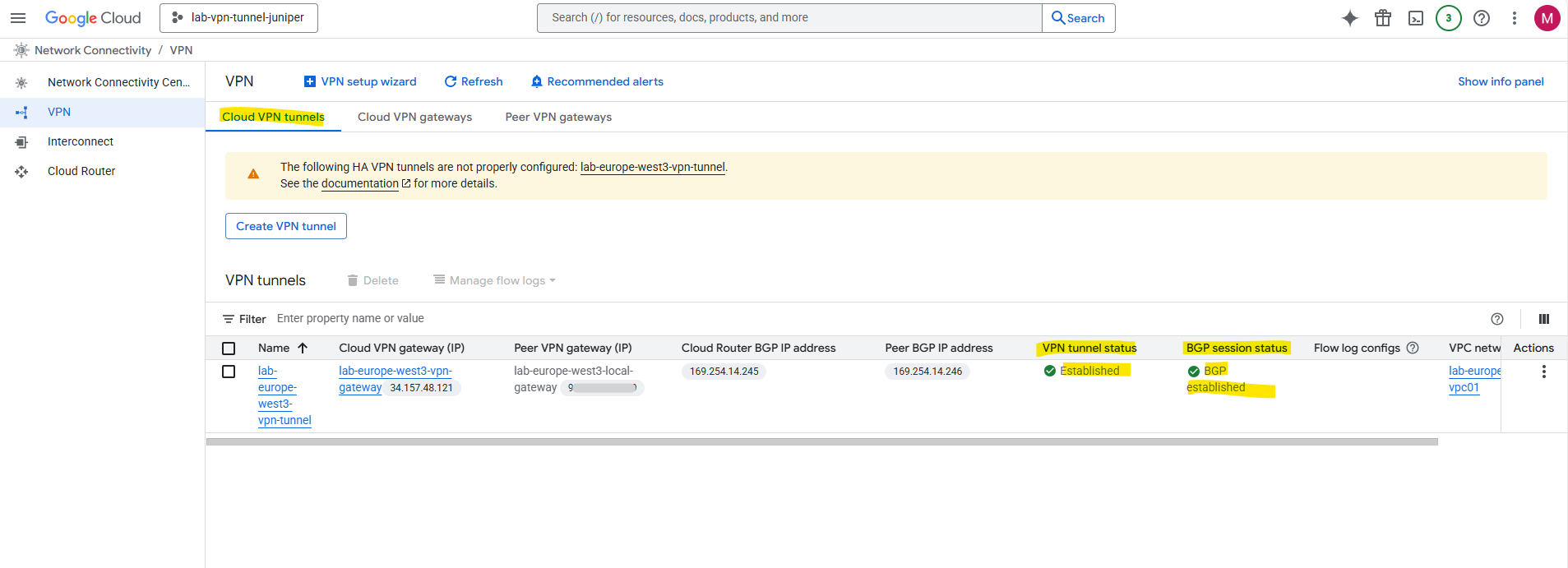
By using Google Cloud SDK (gcloud).
$ gcloud compute vpn-tunnels list

gcloud compute routers get-status <ROUTER_NAME> \
    --region=<REGION> \
    --project=<PROJECT_ID> \
    --format="value(result.bgpPeerStatus.state)"


$ gcloud compute routers get-status lab-europe-west3-bgp-router --region=europe-west3 --project=lab-vpn-tunnel-juniper --format="value(result.bgpPeerStatus.state)"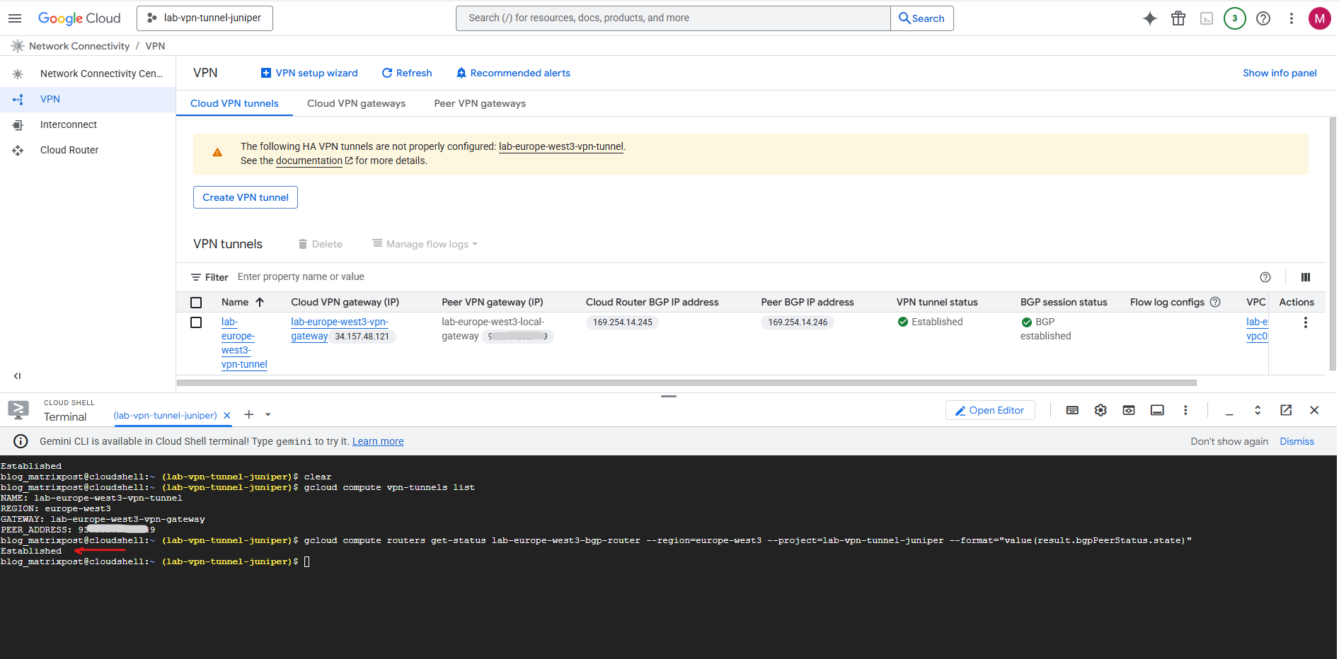
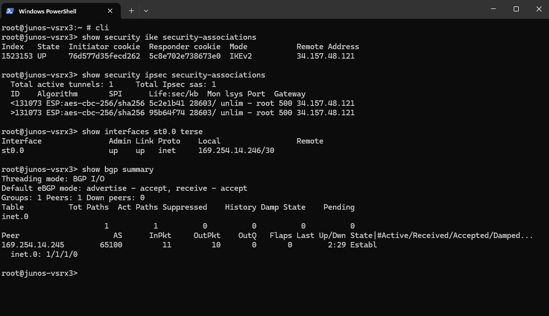
Checking the BGP state on Juniper.
root@junos-vsrx3:~ # cli
root@junos-vsrx3> show security ike security-associations
root@junos-vsrx3> show security ipsec security-associations
root@junos-vsrx3> show interfaces st0.0 terse
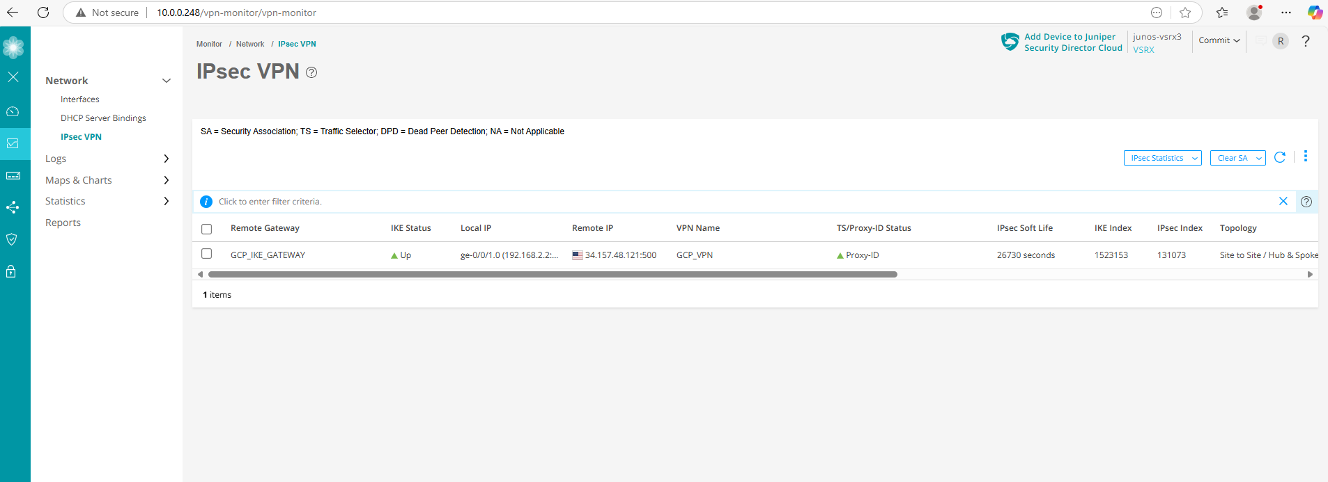
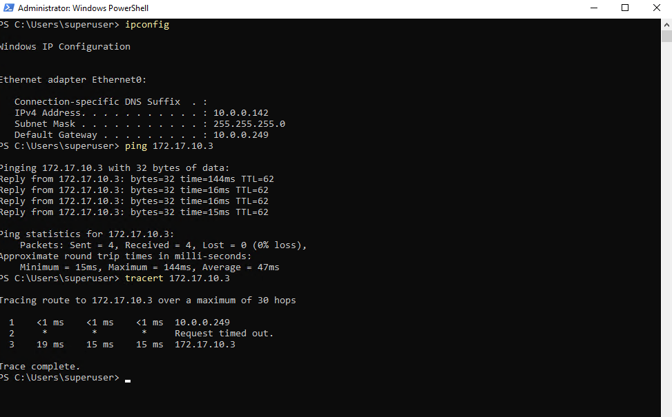
I will also check if I can connect to my GCP virtual machine‘s private IP address 172.17.10.3 from my on-premise lab environment.
Looks good.
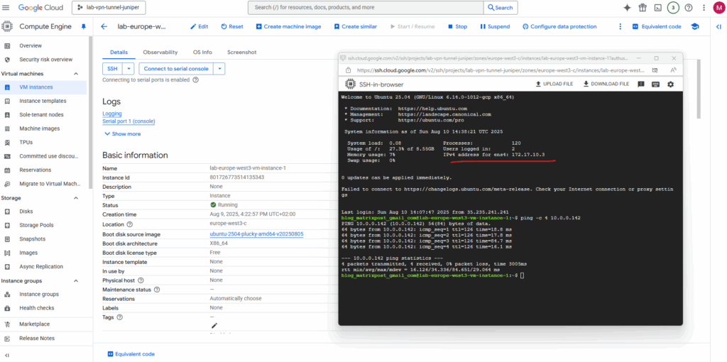
Also traffic initiated from GCP to my on-premise lab network works.
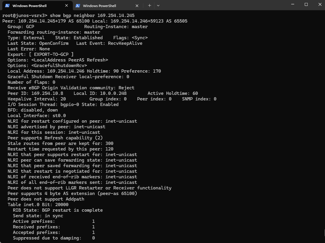
show bgp neighbor
This command displays detailed information about a BGP neighbor in Junos OS.
show bgp neighbor 169.254.14.245
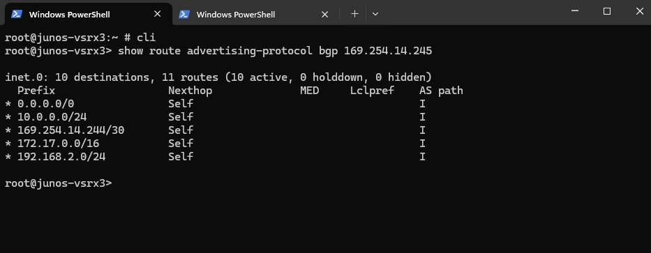
Show advertised Routes by Juniper to Azure
This command shows the routes that your Juniper device is advertising to the BGP peer at IP 169.254.14.245 (here the GCP Cloud Router).
show route advertising-protocol bgp 169.254.14.245
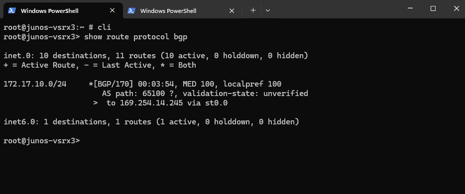
Show advertised Routes by GCP
This command displays all routes learned via BGP on your Juniper vSRX, meaning these are routes received from BGP peers (here from GCP).
show route protocol bgp
Show advertised Routes by Juniper using the Google Cloud Console
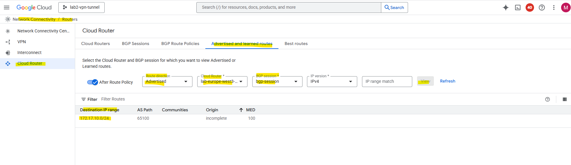
In the Google Cloud Console under Network Connectivity -> Cloud Routers -> Advertised and learned routes we can see the learned routes from on-premise and advertised by our Juniper vSRX appliance to GCP.
For the route direction select Learned.
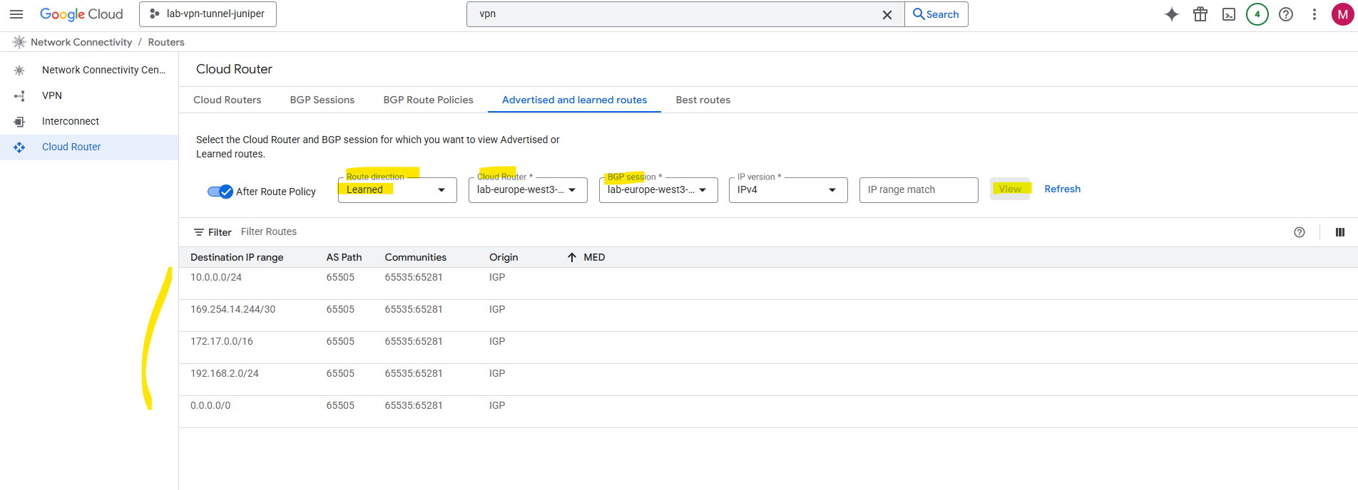
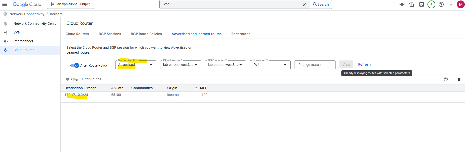
Here we can also select Advertised for the route direction to see which routes GCP will advertise to on-premise.
We can also use the gcloud to see the learned routes from on-premise by running the following command.
$ gcloud compute routers get-status ROUTER_NAME \
    --region=REGION \
    --format="yaml(result.bestRoutesForRouter)"

$ gcloud compute routers get-status lab-europe-west3-bgp-router --region=europe-west3 --format="yaml(result.bestRoutesForRouter)"
Links
Classic VPN dynamic routing deprecation
https://cloud.google.com/network-connectivity/docs/vpn/deprecations/classic-vpn-deprecation?utm_source=chatgpt.comAbout Hybrid Subnets
https://cloud.google.com/vpc/docs/hybrid-subnetsSupported IKE ciphers
https://cloud.google.com/network-connectivity/docs/vpn/concepts/supported-ike-ciphersSRX Series Firewalls
https://www.juniper.net/us/en/products/security/srx-series.htmlJuniper Licensing User Guide
https://www.juniper.net/documentation/us/en/software/license/juniper-licensing-user-guide/index.htmlvSRX Deployment Guide for VMware
https://www.juniper.net/documentation/us/en/software/vsrx/vsrx-vmware/vsrx-vmware.pdfvSRX Virtual Firewall User Guide for Private and Public Cloud Platforms
https://www.juniper.net/documentation/us/en/software/vsrx/vsrx-consolidated-user-guide/vsrx-consolidated-user-guide.pdfAdd vSRX Virtual Firewall Interfaces
https://www.juniper.net/documentation/us/en/software/vsrx/vsrx-consolidated-deployment-guide/vsrx-vmware/topics/task/security-vsrx-vmware-adding-interfaces-update.htmlUser Access and Authentication Administration Guide for Junos OS
https://www.juniper.net/documentation/us/en/software/junos/user-access/topics/topic-map/user-access-root-password.htmlJuniper vSRX Setup & Initial Configuration Guide
https://journey2theccie.wordpress.com/2021/02/04/juniper-vsrx-setup-initial-configuration-guide/Security Zones
https://www.juniper.net/documentation/us/en/software/junos/security-policies/topics/topic-map/security-zone-configuration.htmlsystem-services (Security Zones Host Inbound Traffic)
https://www.juniper.net/documentation/us/en/software/junos/cli-reference/topics/ref/statement/security-edit-system-service-zone-host-inbound-traffic.htmlExample: Configuring NAT for vSRX Virtual Firewall
https://www.juniper.net/documentation/us/en/software/vsrx/vsrx-consolidated-deployment-guide/vsrx-aws/topics/example/security-vsrx-example-aws-nat.htmlMonitor Log Messages
https://www.juniper.net/documentation/us/en/software/junos/network-mgmt/topics/topic-map/displaying-and-interpreting-system-log-message-descriptions.html