Microsoft Hyper-V Networking Best Practices – Part 3 – Configuring iSCSI Storage, Cluster Shared Volumes, and Live Migration
In Part 2, we configured the Hyper-V networking using Switch Embedded Teaming (SET) and created our two-node Failover Cluster.
In this part, we will extend the cluster with shared iSCSI storage, configure a Cluster Shared Volume (CSV), migrate our existing virtual machines to shared storage, make them highly available clustered VMs, and test Live Migration and automatic failover.
In Part 4, we will deploy and explore System Center Virtual Machine Manager (SCVMM) for centralized management of our Hyper-V environment and compare its architecture, features, and management experience with VMware vCenter.
Besides using traditional shared storage such as iSCSI, Microsoft Hyper-V clusters can also use Storage Spaces Direct (S2D) to aggregate locally attached disks across the cluster nodes into highly available shared storage. For a detailed walkthrough of this approach, see my following post.
- Prepare the Shared iSCSI Storage on Synology
- Connect the Hyper-V Hosts to the iSCSI Target
- Configure Shared Storage and Cluster Shared Volumes (CSV)
- Configure the Cluster Disk as a Cluster Shared Volume (CSV)
- Migrating Existing Hyper-V Virtual Machines to Highly Available Clustered VMs
- Testing Automatic Failover of a Highly Available Virtual Machine
- Links
Prepare the Shared iSCSI Storage on Synology
Before connecting our Hyper-V hosts to shared storage, we first need to prepare an iSCSI LUN on the Synology NAS.
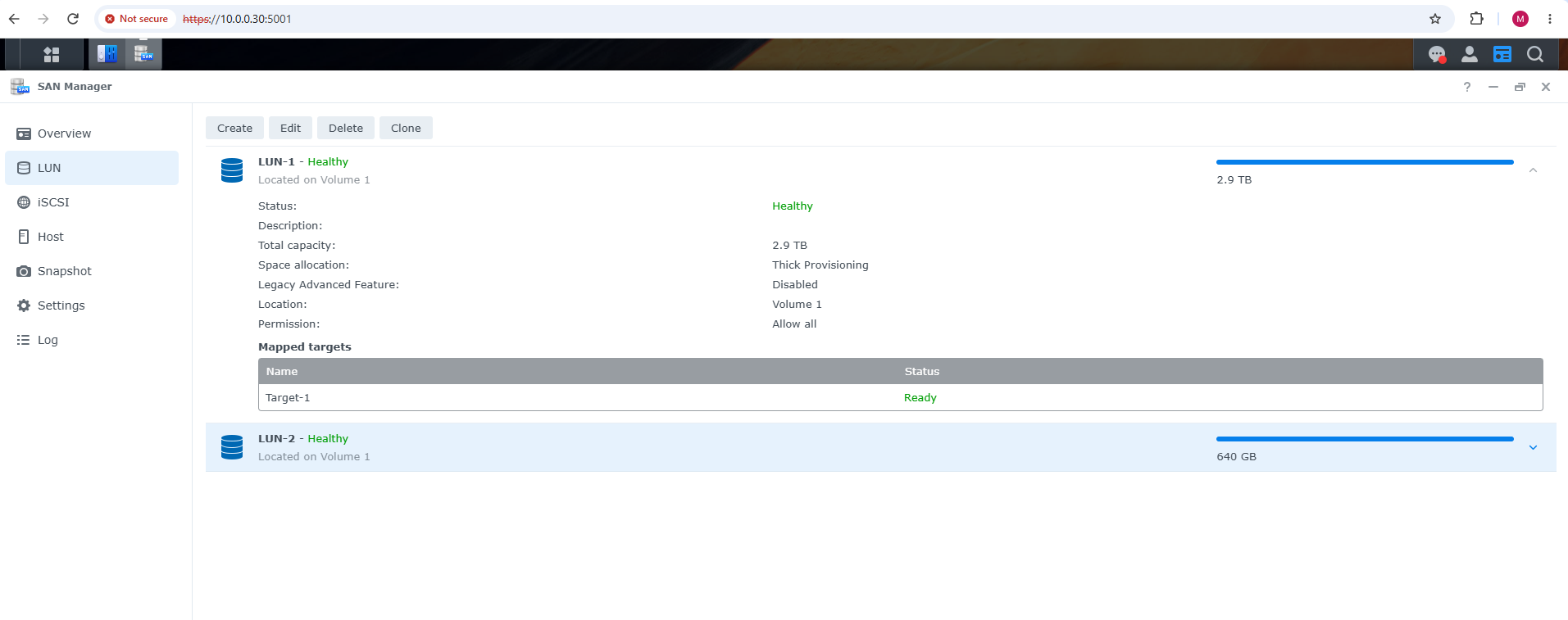
On my Synology DS124, most of the available storage is already used by my VMware vSphere lab, but I could allocate the remaining 640 GB as a dedicated LUN for our Hyper-V Failover Cluster.
As shown below, the new LUN-2 is healthy and provides 640 GB of capacity.
In the next step, we will create/configure the corresponding iSCSI target and make the LUN accessible to both Hyper-V cluster.
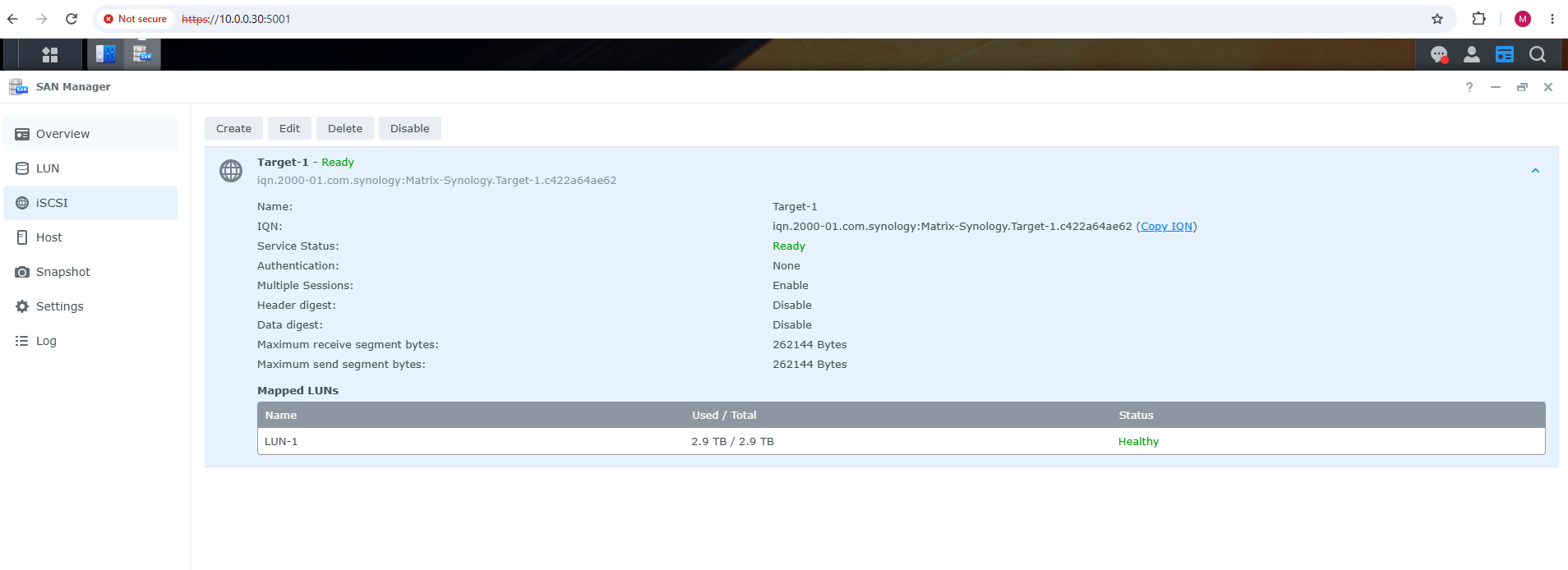
Here we can see the existing iSCSI target Target-1, which is currently mapped only to the 2.9 TB LUN-1 used by the vSphere environment.
For our Hyper-V cluster, we will therefore create a separate iSCSI target and map the newly created 640 GB LUN-2 to it, keeping both lab environments cleanly separated.
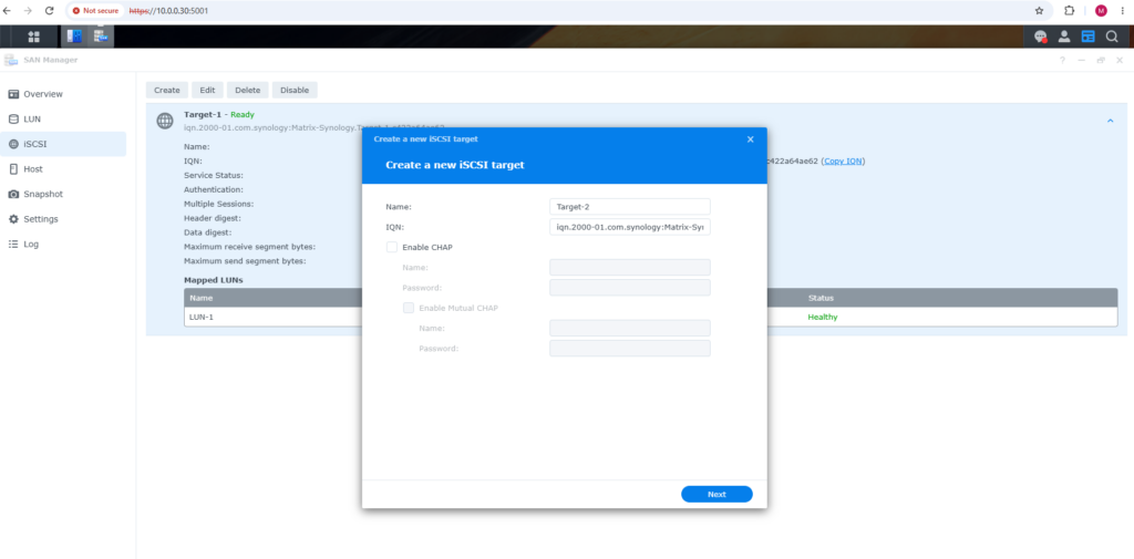
For the Hyper-V cluster, we create a dedicated iSCSI target (Target-2), which also gets its own unique IQN (iSCSI Qualified Name) used to identify the target.
For this lab, we leave CHAP authentication disabled; in production environments, CHAP can be enabled to authenticate iSCSI initiators connecting to the target.
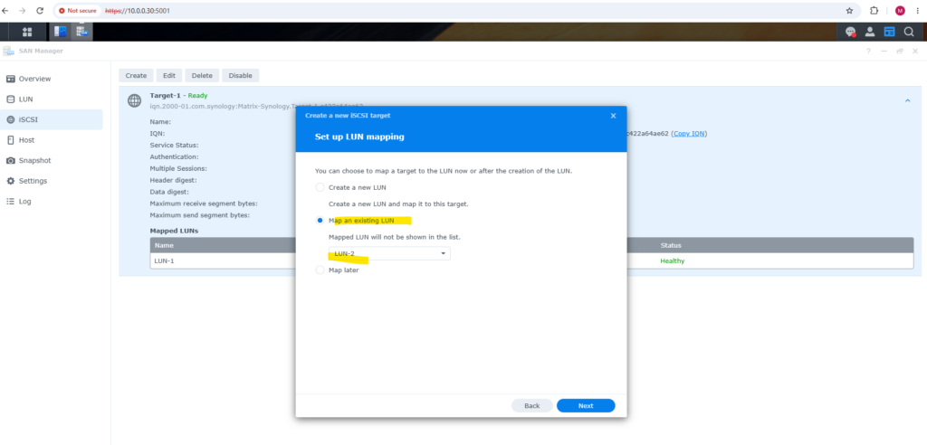
Next, we map the existing 640 GB LUN-2 to our newly created Hyper-V iSCSI target. This ensures that only the LUN dedicated to the Hyper-V lab is presented through this target, while the existing 2.9 TB LUN-1 remains associated with the separate vSphere target.
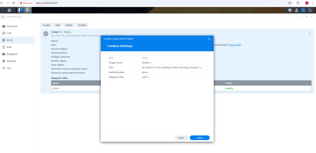
Finally, we review the configuration before creating the target. The summary confirms that Target-2 has its own IQN, uses no CHAP authentication, and is mapped exclusively to LUN-2; clicking Done completes the iSCSI target configuration.
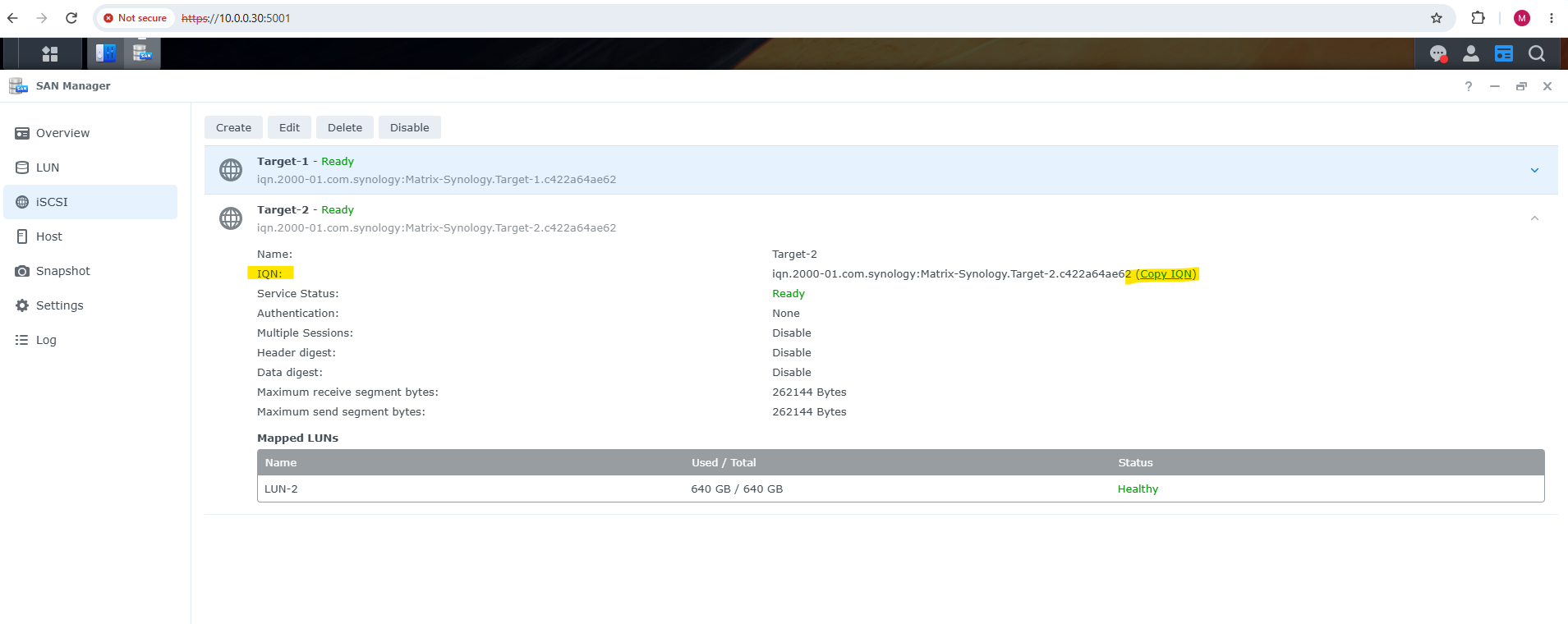
The newly created Target-2 is now shown as Ready and the dedicated 640 GB LUN-2 is successfully mapped to it. We can also copy the target’s IQN, which uniquely identifies this iSCSI target and can be used when configuring access from our Hyper-V hosts.
Connect the Hyper-V Hosts to the iSCSI Target
With the Synology iSCSI target and LUN prepared, we can now connect our Hyper-V cluster nodes to the shared storage.
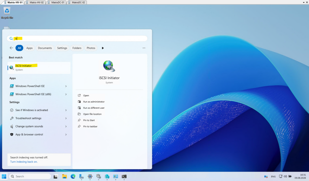
On Matrix-HV-01, open the built-in iSCSI Initiator from the Windows Start menu; we will configure the Synology NAS as the target portal and establish the iSCSI connection.
The same configuration will subsequently be performed on
Matrix-HV-02, because both cluster nodes must have access to the same shared LUN.
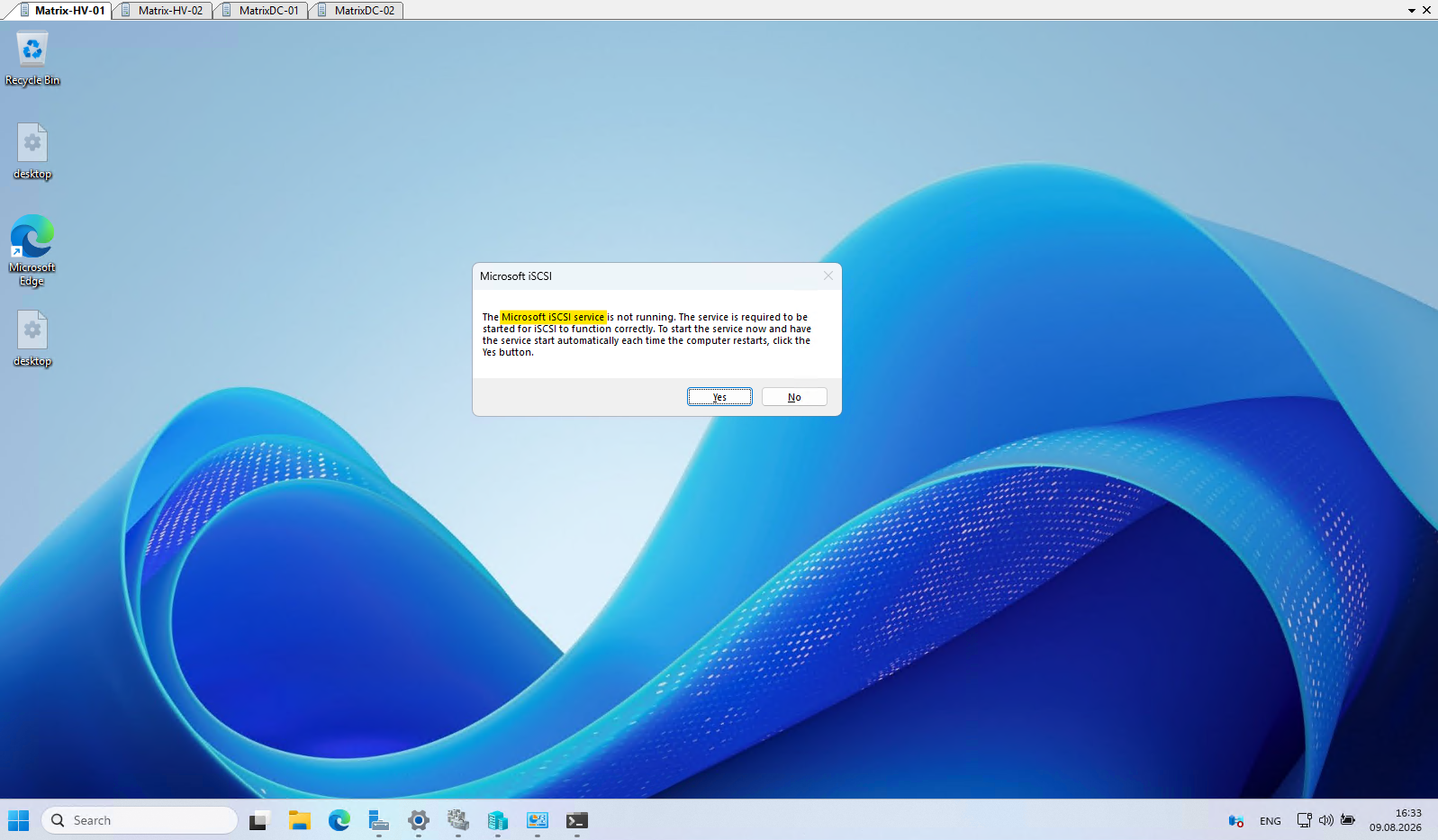
When opening the iSCSI Initiator for the first time, Windows may report that the Microsoft iSCSI service is not running.
Click Yes to start the service and configure it to start automatically, ensuring that the iSCSI connections can also be restored automatically after the Hyper-V host is rebooted.
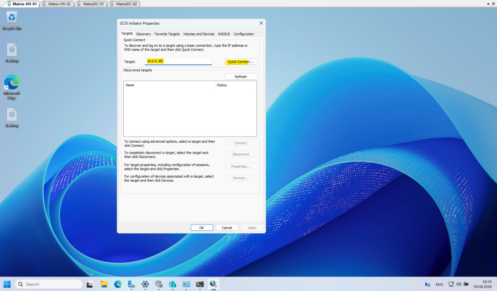
Now we enter the IP address of the Synology NAS (10.0.0.30) in the Target field and click Quick Connect.
The iSCSI Initiator uses this address as the target portal to discover the iSCSI targets published by the Synology, from which we can then connect to our dedicated
Target-2.
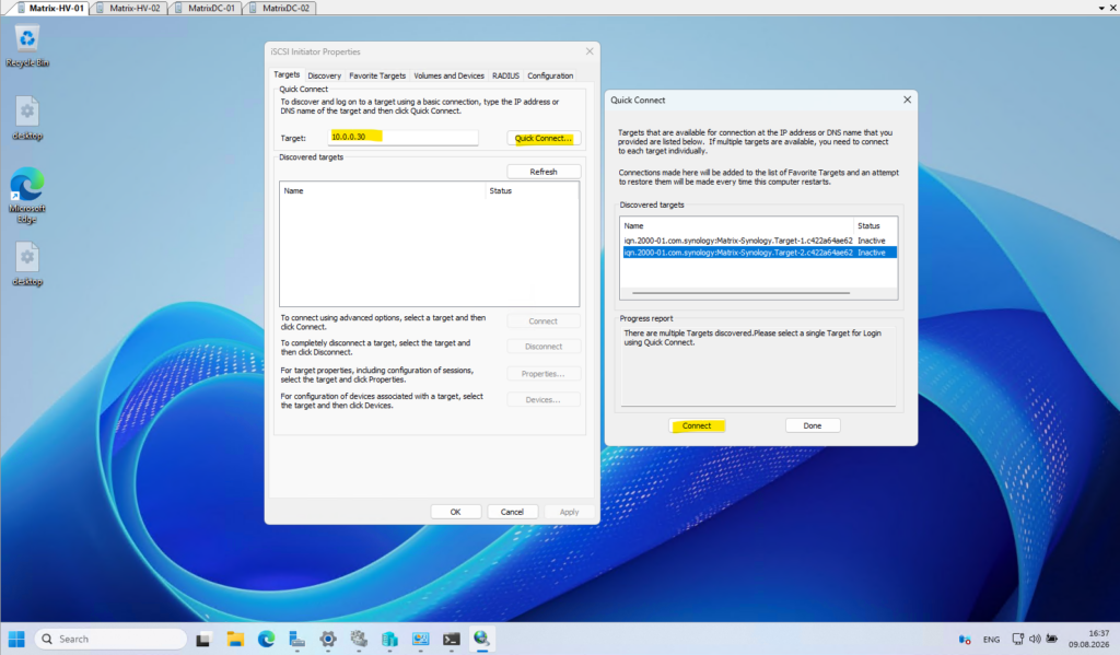
Select the Target-2 IQN from the discovered targets and click Connect.
Windows will establish an iSCSI session to this specific target and automatically add the connection to the Favorite Targets, allowing it to be restored after a reboot.
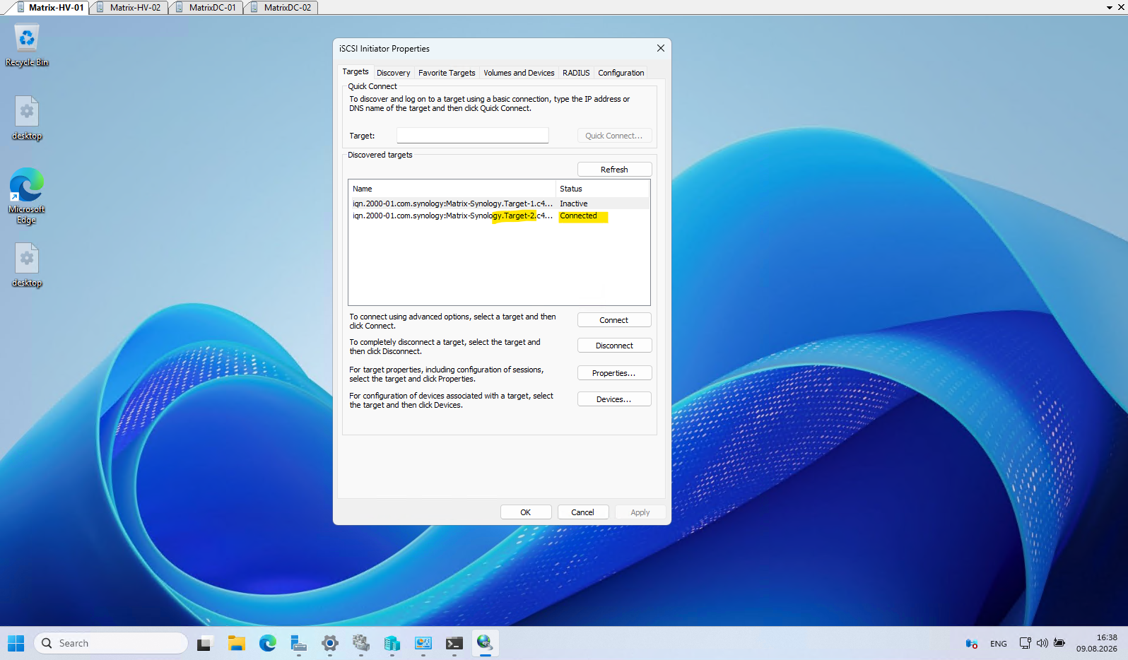
The connection to
Target-2is now established successfully and its status changes to Connected, while the existingTarget-1remains Inactive. This confirms that the Hyper-V host is connected only to the dedicated iSCSI target and therefore only to the 640 GB LUN-2 mapped to it.
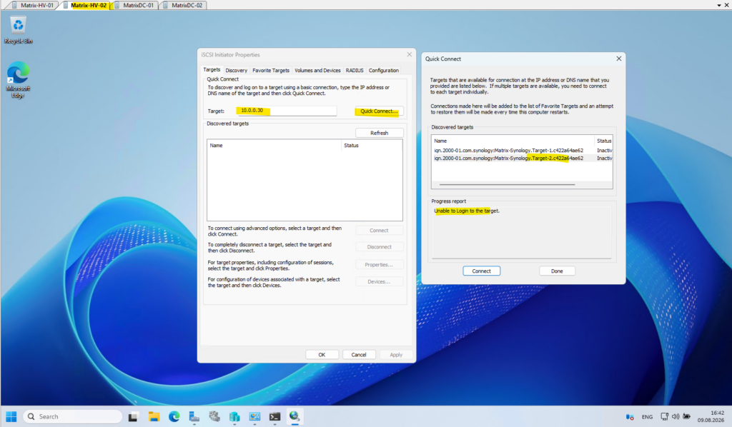
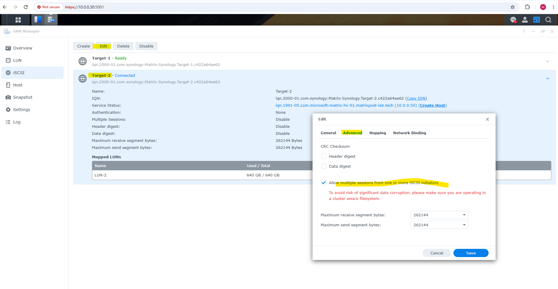
Because the iSCSI LUN will be used as shared storage by both Hyper-V cluster nodes, the Synology iSCSI target must allow multiple sessions.
Otherwise, after the first Hyper-V host connects successfully, additional cluster nodes like my
Matrix-HV-02below fail with “Unable to Login to the target.”
On the Synology we can edit the iSCSI target under Advanced and enable Allow multiple sessions from one or more iSCSI initiators.
Synology explicitly warns that shared access requires a cluster-aware filesystem, which is exactly what we will provide by adding the disk to the Windows Failover Cluster and configuring it as a Cluster Shared Volume (CSV).
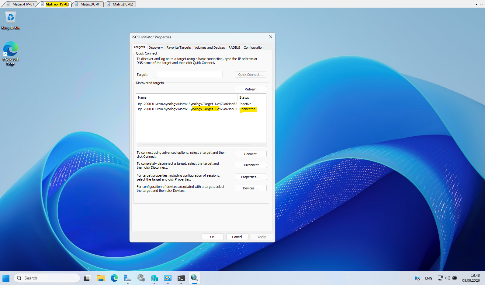
After enabling multiple sessions, the connection from the second Hyper-V host succeeds as well as shown below.
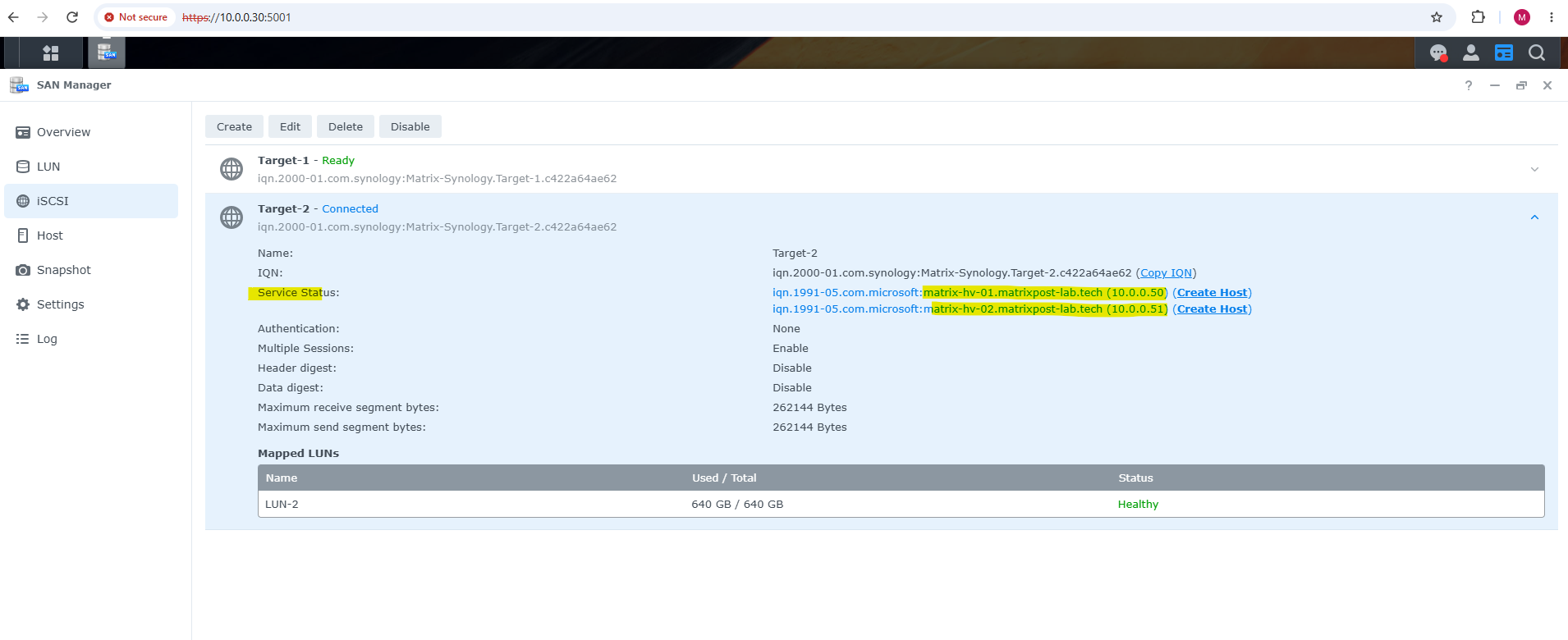
The Synology SAN Manager now shows two active iSCSI initiators,
Matrix-HV-01(10.0.0.50) andMatrix-HV-02(10.0.0.51), both connected toTarget-2and therefore able to access the same 640 GB LUN-2.
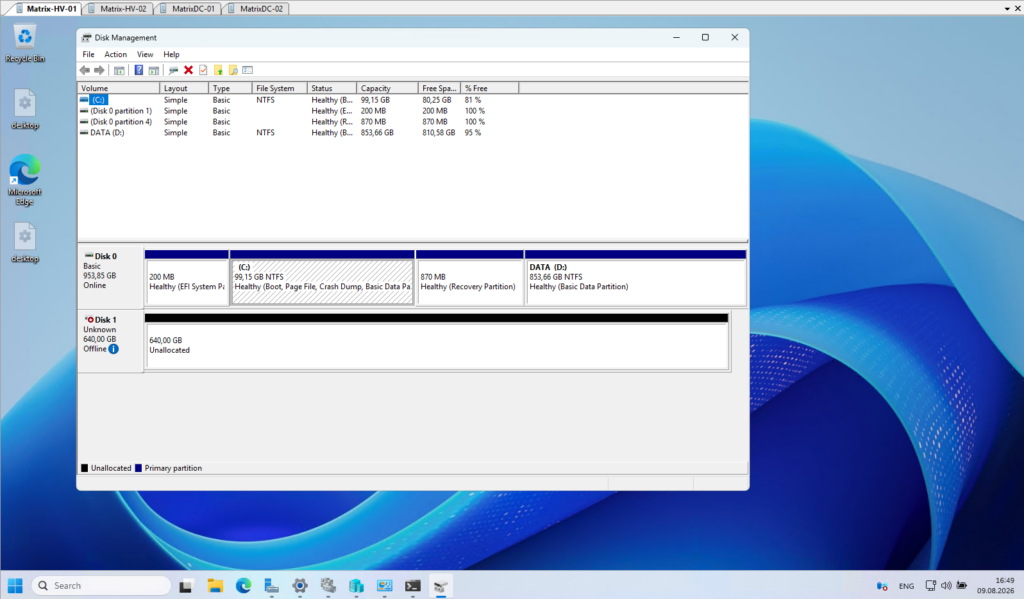
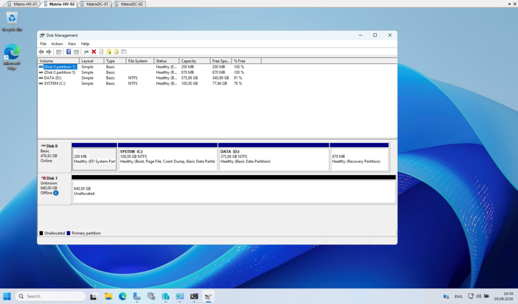
After connecting both Hyper-V hosts to the iSCSI target, the 640 GB LUN becomes visible as Disk 1 in Disk Management on both cluster nodes.
At this point, the disk is still Unknown, Offline, and Unallocated, confirming that both hosts can see the same shared block storage.
Configure Shared Storage and Cluster Shared Volumes (CSV)
With the iSCSI target connected to both Hyper-V cluster nodes, the shared 640 GB LUN is now visible to both hosts.
Next, we will add this disk to the Failover Cluster, prepare it for clustered use, and finally configure it as a Cluster Shared Volume (CSV) so that both Hyper-V nodes can simultaneously access the storage used for our highly available virtual machines.
Add the Shared Disk to the Failover Cluster
Now that the shared iSCSI LUN is visible on both Hyper-V hosts, we can hand control of the disk over to Failover Clustering.
Open Failover Cluster Manager and navigate to:
Storage → Disks → Add Disk
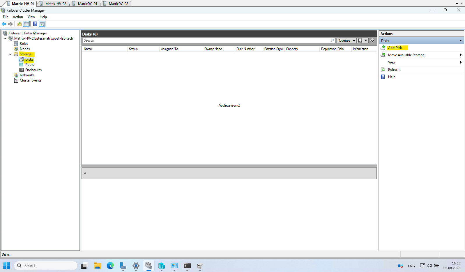
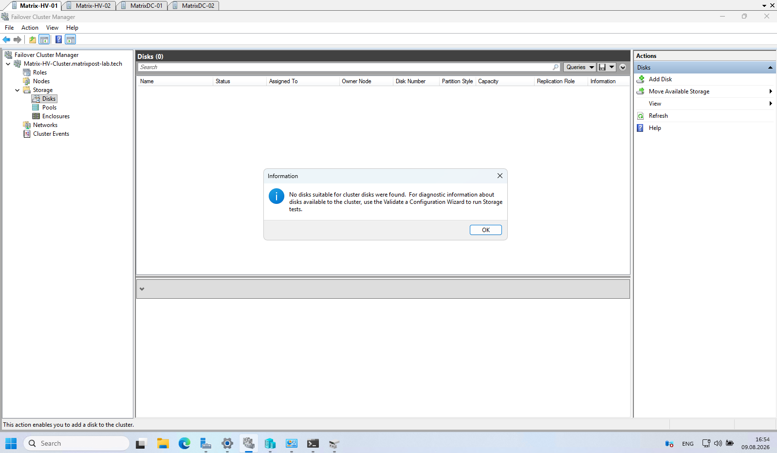
The wizard should automatically detect the 640 GB iSCSI LUN as storage that is available to be added to the cluster. Select the disk and click OK.
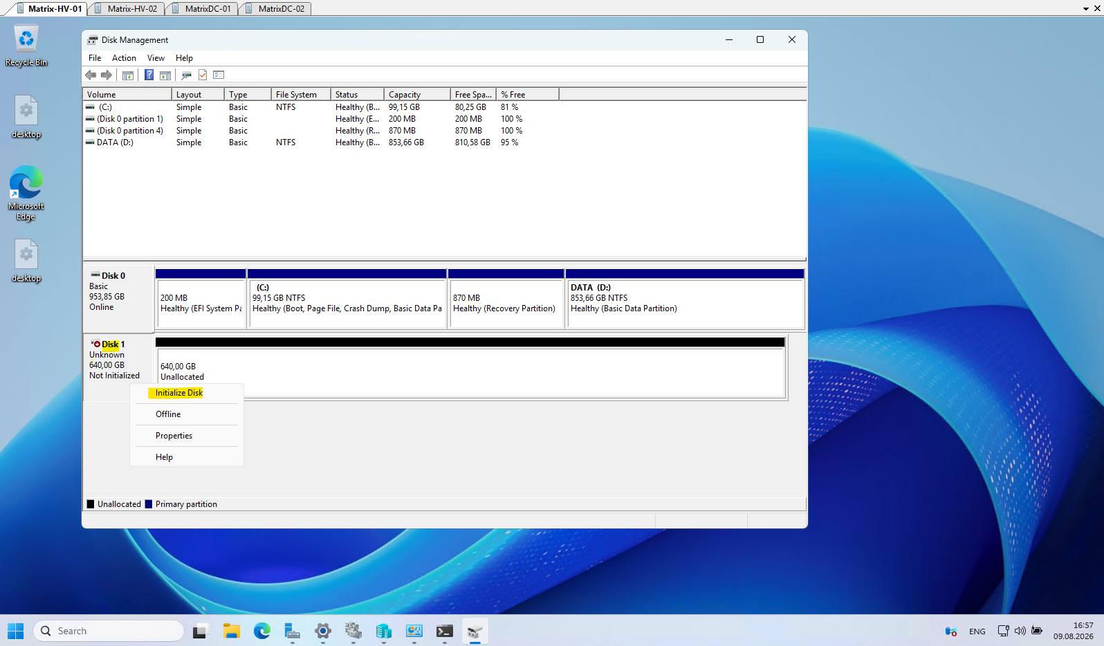
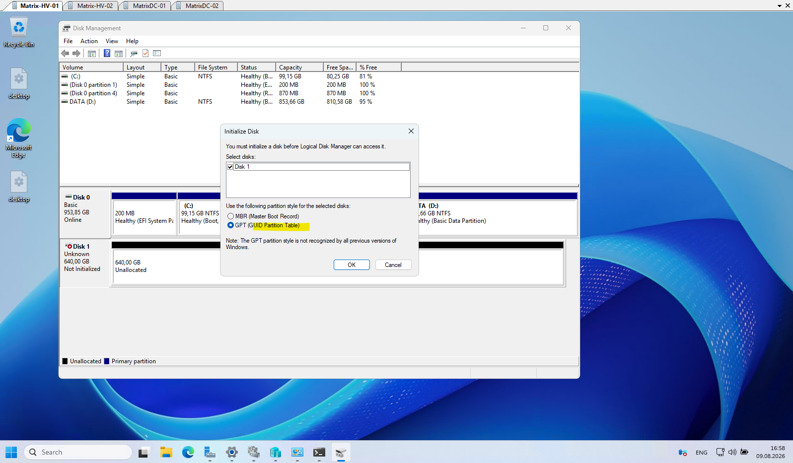
The disk must first be initialized before it can be used by the failover cluster.
On one cluster node, bring the newly presented iSCSI disk Online in Disk Management. The disk is currently shown as Unknown, Offline, and Unallocated and must first be initialized before it can be used by the failover cluster.
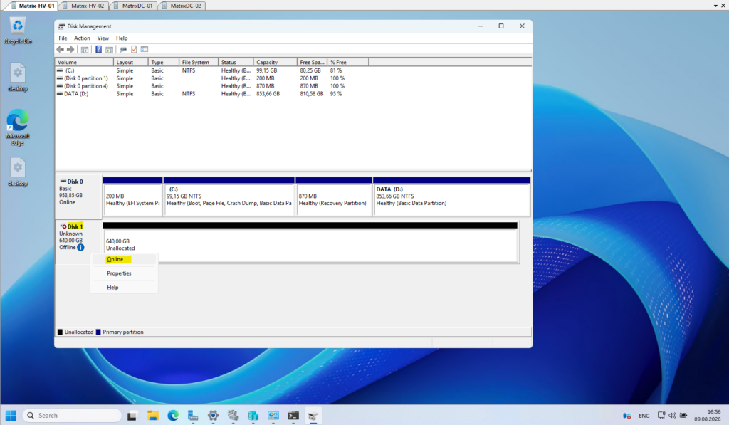
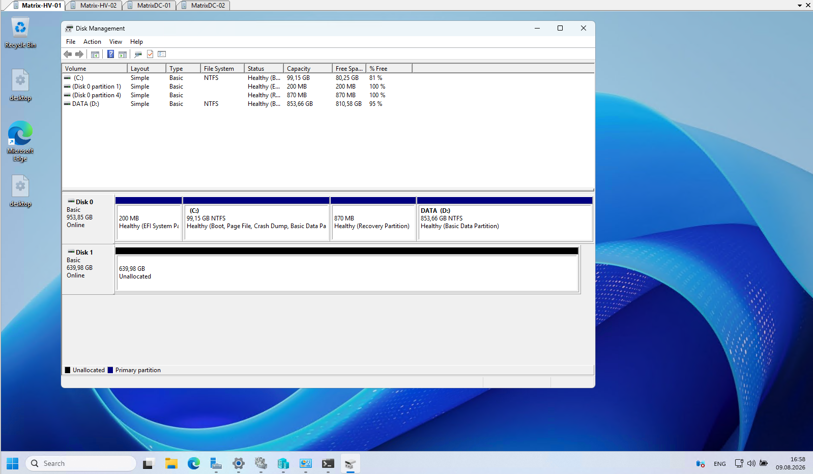
After bringing the disk online, it is now detected as a Basic 640 GB disk and remains completely unallocated.
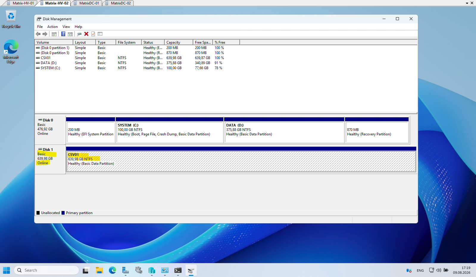
Before adding the disk to the Failover Cluster, we also need to create and format the volume on the current owner node, the node where the disk is shown without the red down-arrow icon in Disk Management, without assigning a drive letter.
The disk is now fully prepared and can be added back to the cluster and subsequently converted into a Cluster Shared Volume (CSV).
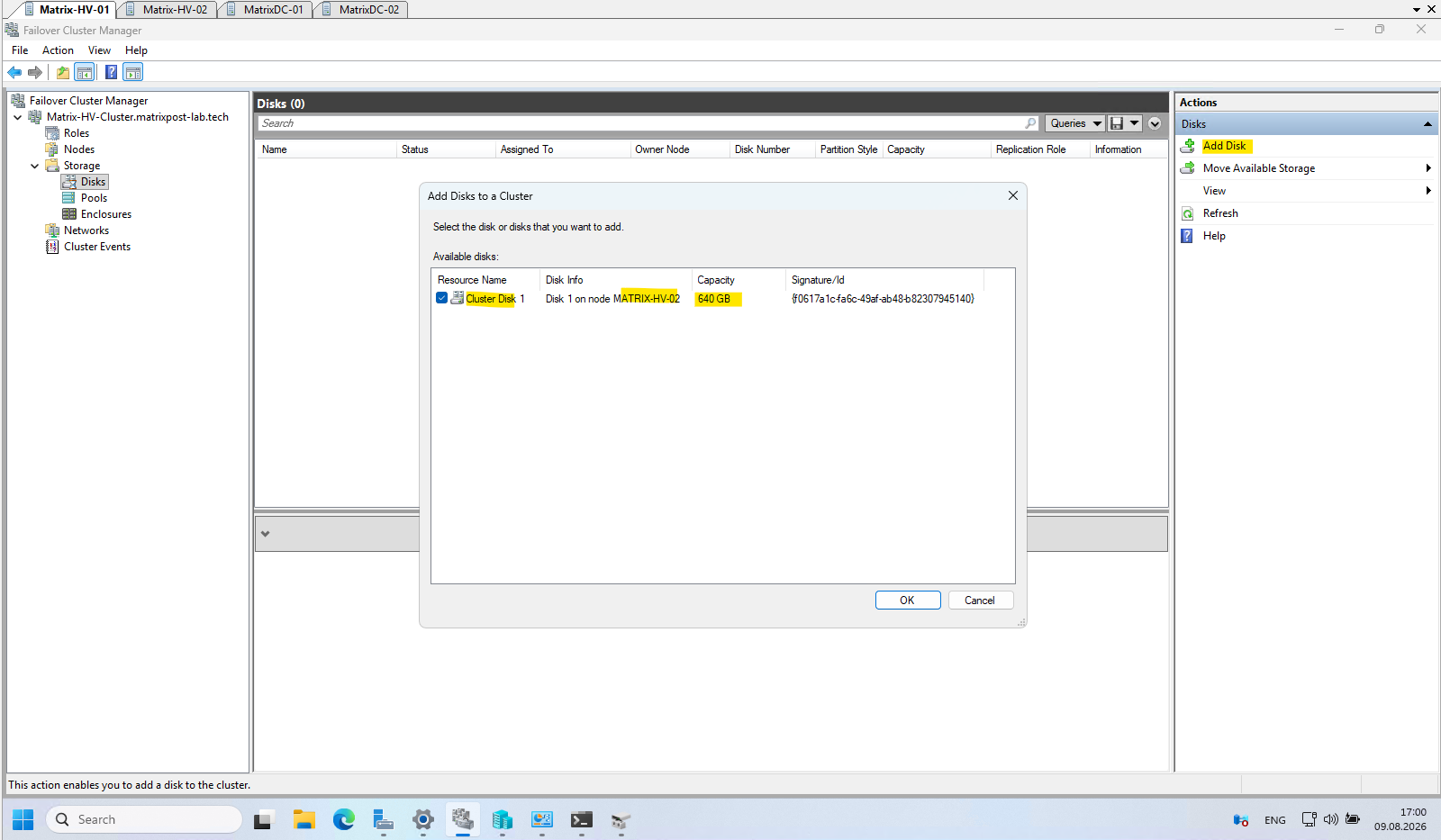
Return to Failover Cluster Manager → Storage → Disks → Add Disk.
A small but interesting detail is that the wizard identifies the available LUN as “Disk 1 on node MATRIX-HV-02”, even though Failover Cluster Manager is currently opened on MATRIX-HV-01.
This indicates that MATRIX-HV-02 is currently reporting the disk as eligible; once added as a clustered disk, ownership is controlled by the failover cluster and can move between the nodes.
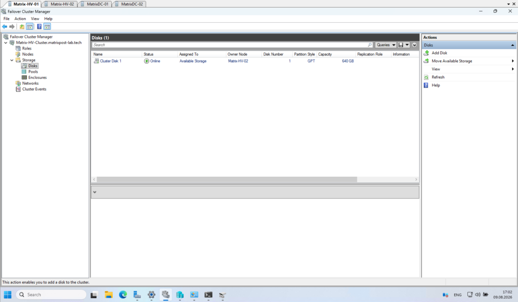
Once added, the disk becomes a cluster-managed resource, meaning its ownership and online/offline state are coordinated by the Failover Cluster rather than independently by each Hyper-V host.
After adding the disk, Cluster Disk 1 is shown as Online and assigned to Available Storage. We can also see that MATRIX-HV-02 is currently the Owner Node, confirming that this node presently controls the clustered disk resource; ownership can later be moved automatically or manually to the other cluster node.
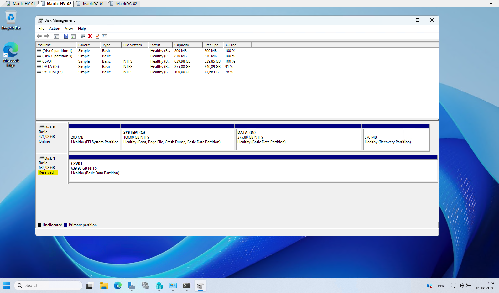
After adding the disk to the failover cluster, Disk Management shows the shared LUN as Reserved on both cluster nodes.
The disk is now controlled by the Windows Failover Cluster, with MATRIX-HV-02 currently acting as the Owner Node, as shown previously in Failover Cluster Manager.
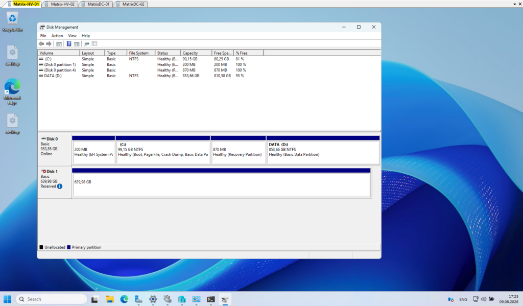
On MATRIX-HV-01, the disk additionally shows a red down-arrow, indicating that it is not locally online on this node, while MATRIX-HV-02 is currently the Owner Node controlling the clustered disk resource.
Configure the Cluster Disk as a Cluster Shared Volume (CSV)
Now that the shared iSCSI disk has been successfully added to the failover cluster, the next step is to convert it into a Cluster Shared Volume (CSV).
A CSV allows both Hyper-V nodes to access the same volume simultaneously through a common namespace, which is required for storing highly available virtual machines and enabling seamless Live Migration between the nodes.
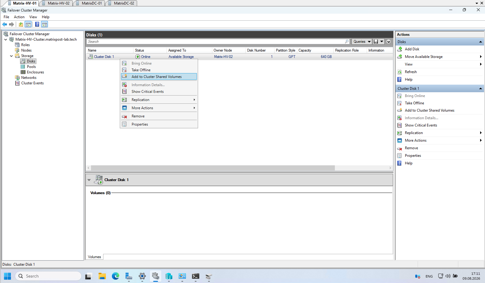
In Failover Cluster Manager, navigate to Storage → Disks, right-click Cluster Disk 1, and select Add to Cluster Shared Volumes. Windows will configure the disk as a CSV and make it available to the cluster through the common C:\ClusterStorage namespace.
The volume CSV01 is now mounted automatically as C:\ClusterStorage\Volume1 and is available as shared storage to all nodes in the cluster.
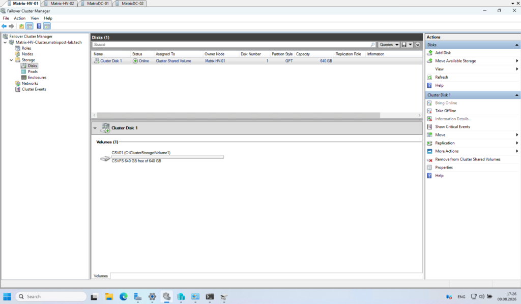
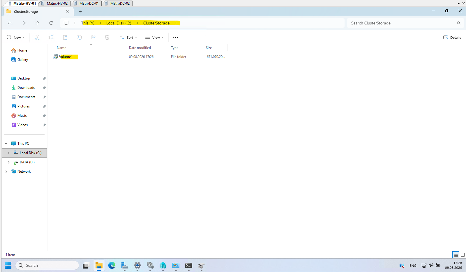
Once added as a Cluster Shared Volume (CSV), Windows automatically creates the
C:\ClusterStoragedirectory and mounts the shared volume below it, in our case asC:\ClusterStorage\Volume1.The same CSV path is available on all nodes of the Failover Cluster, allowing clustered Hyper-V workloads to access the shared storage regardless of which node currently owns or runs the VM.
Migrating Existing Hyper-V Virtual Machines to Highly Available Clustered VMs
Existing standalone Hyper-V virtual machines are not automatically protected by the Failover Cluster simply because their hosts are cluster members. To make them highly available, we first need to move their complete VM storage from the local Hyper-V host to the Cluster Shared Volume (CSV) and then add the virtual machines as clustered roles in Failover Cluster Manager.
Once both steps are completed, the VMs are managed by the Failover Cluster and can be moved between cluster nodes or automatically restarted on another available node if their current host fails.
Moving Existing Virtual Machines to the Cluster Shared Volume (CSV)
Now that our Cluster Shared Volume (CSV) is available to both Hyper-V nodes, we can migrate our existing standalone virtual machines to the shared storage and make them highly available clustered VMs.
This allows the Failover Cluster to start or move the virtual machines between both Hyper-V nodes and, most importantly, restart them on the remaining node if one Hyper-V host fails.
Using Hyper-V Manager, move the VM configuration files, checkpoints, Smart Paging files and virtual hard disks from the local host storage to our CSV, for example:C:\ClusterStorage\Volume1\<VM-Name>
In Hyper-V Manager, right-click the VM and select Move.
The virtual machine does not need to be powered off for this operation. Hyper-V supports Storage Live Migration, allowing the VM’s storage to be moved to the Cluster Shared Volume (CSV) while the virtual machine remains online.
Nevertheless, for this lab I powered off the virtual machines before moving their storage.
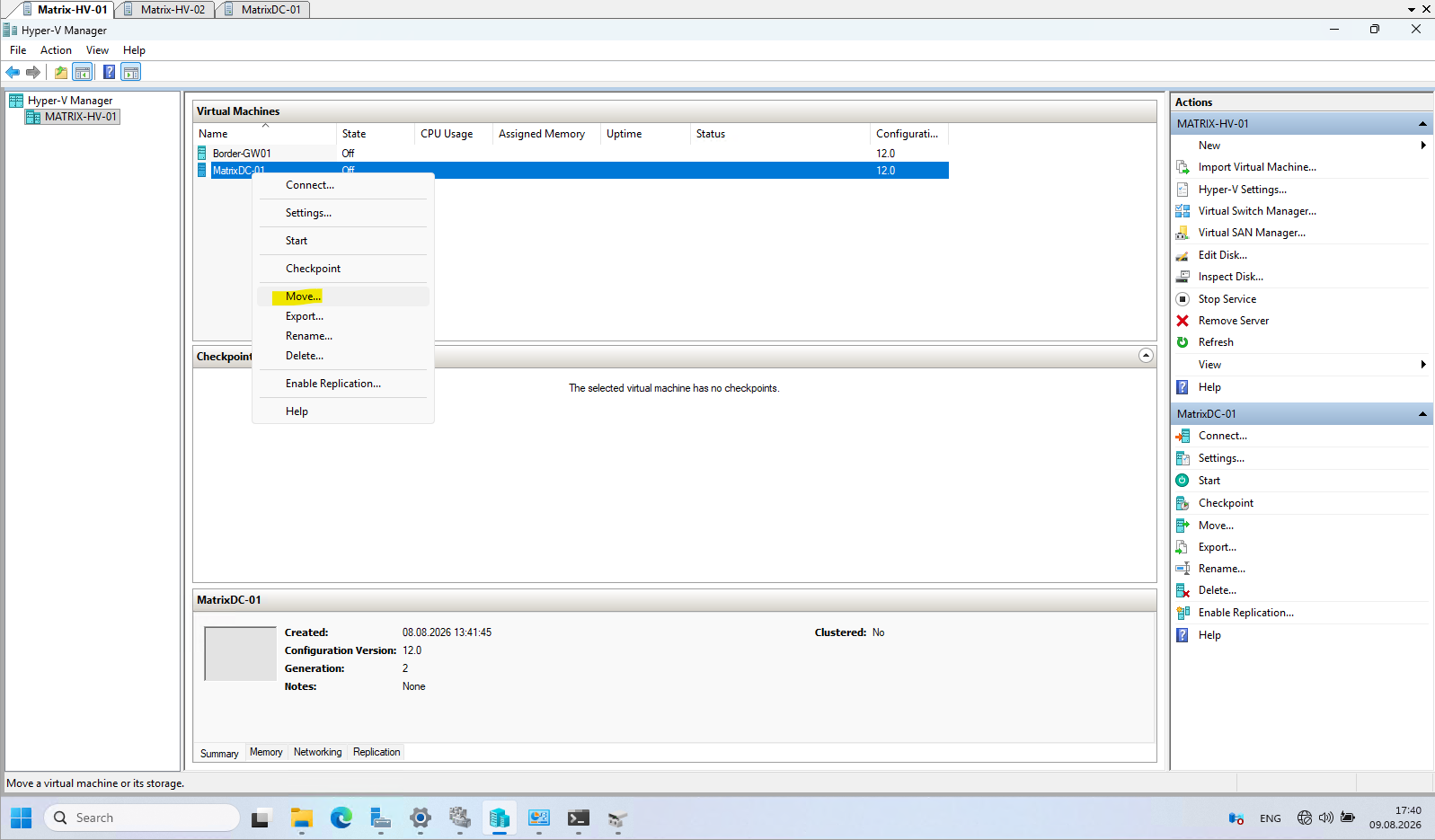
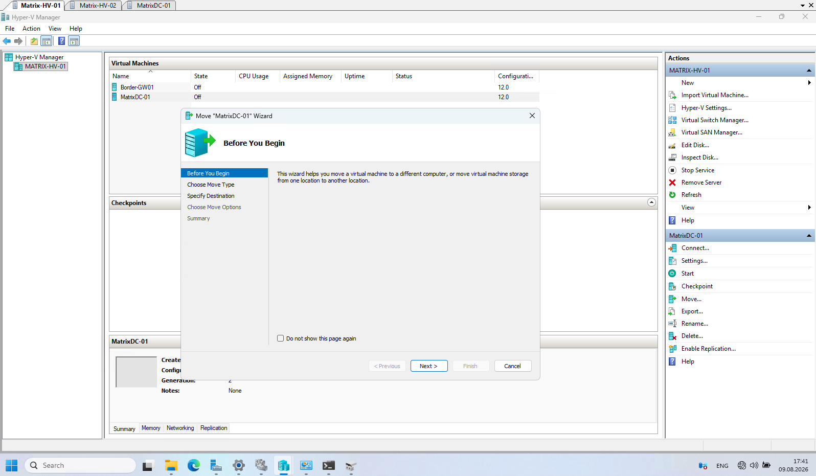
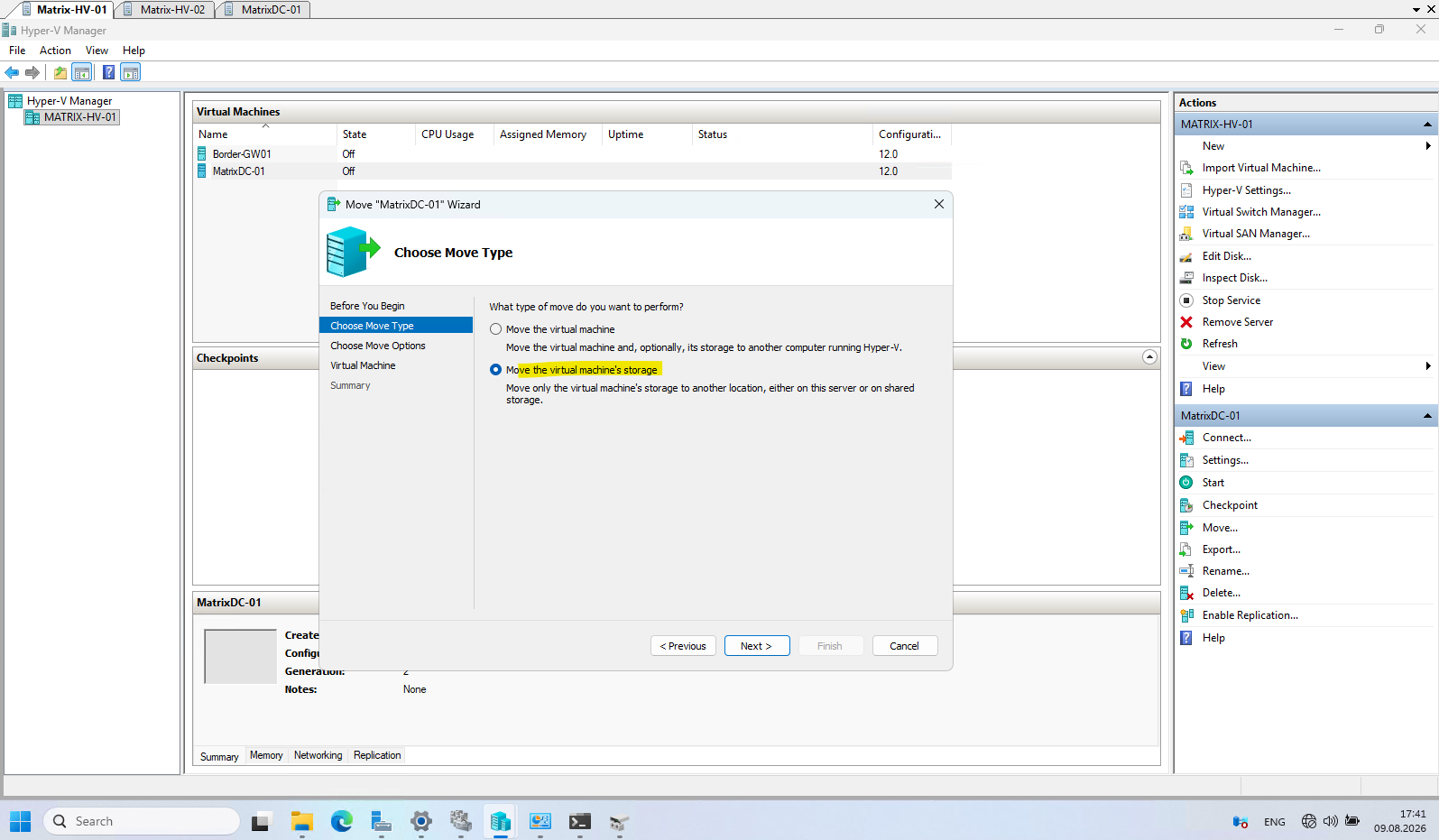
Since we only need to relocate the VM files from the local Hyper-V storage to our newly created CSV, select Move the virtual machine’s storage and click Next.
Here select Move all of the virtual machine’s data to a single location. This ensures that the VM configuration, virtual hard disks, checkpoints, and other associated files are moved together to the Cluster Shared Volume (CSV) rather than leaving parts of the VM on the host’s local storage.
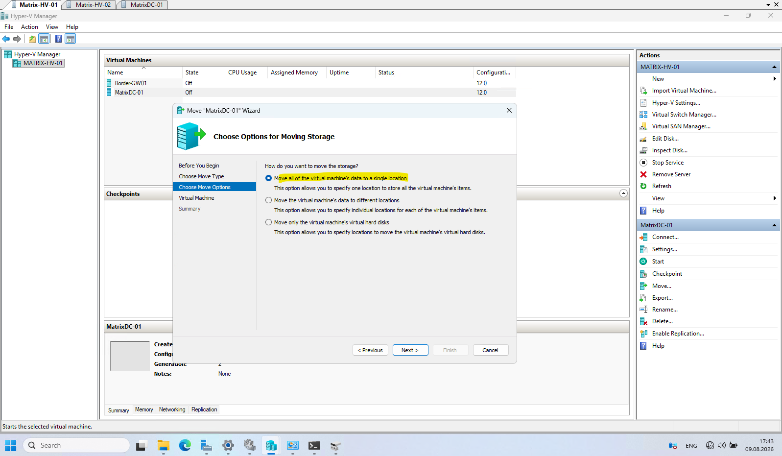
Select Move all of the virtual machine’s data to a single location to move the complete VM to the CSV.
Before proceeding, create a dedicated folder for each VM on the CSV (for example,
C:\ClusterStorage\Volume1\MatrixDC-01); otherwise, the VM files would be stored directly in the root of the CSV.
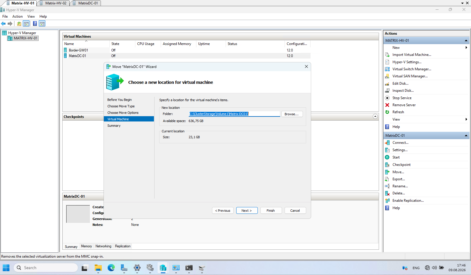
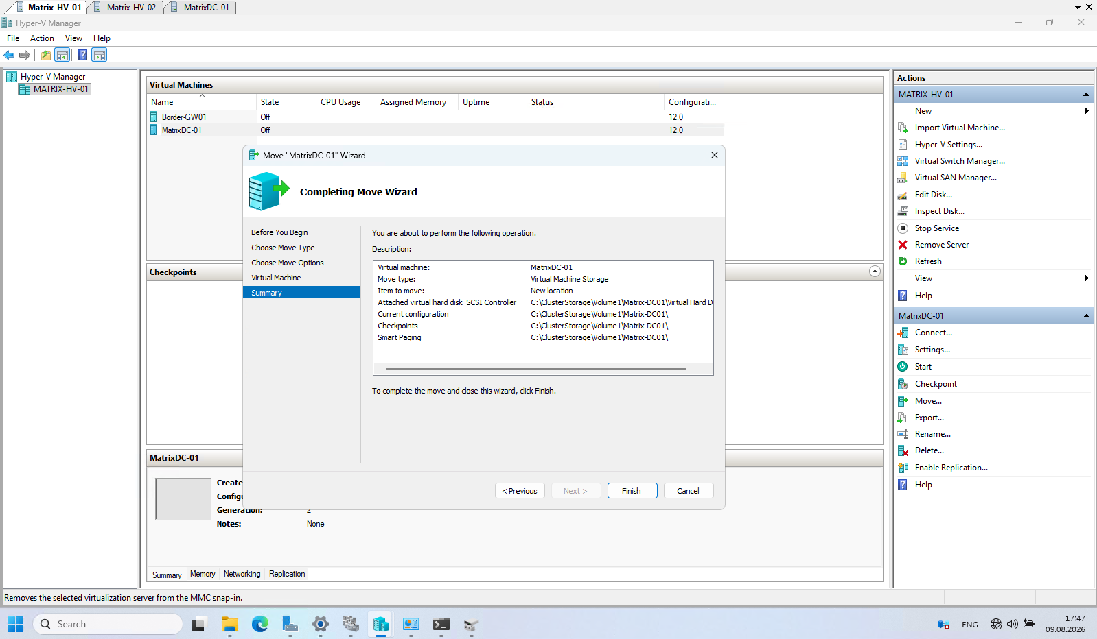
The summary confirms that all VM components will be moved to the dedicated folder C:\ClusterStorage\Volume1\Matrix-DC01\, including the virtual hard disks, configuration files, checkpoints, and Smart Paging files.
Click Finish to start the storage migration to the CSV.
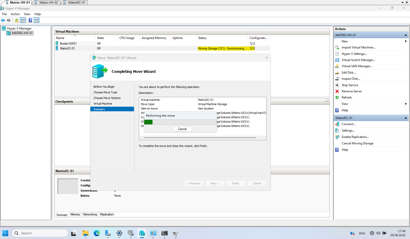
After clicking Finish, Hyper-V starts moving the VM storage to the CSV. The migration progress can be monitored directly in Hyper-V Manager.
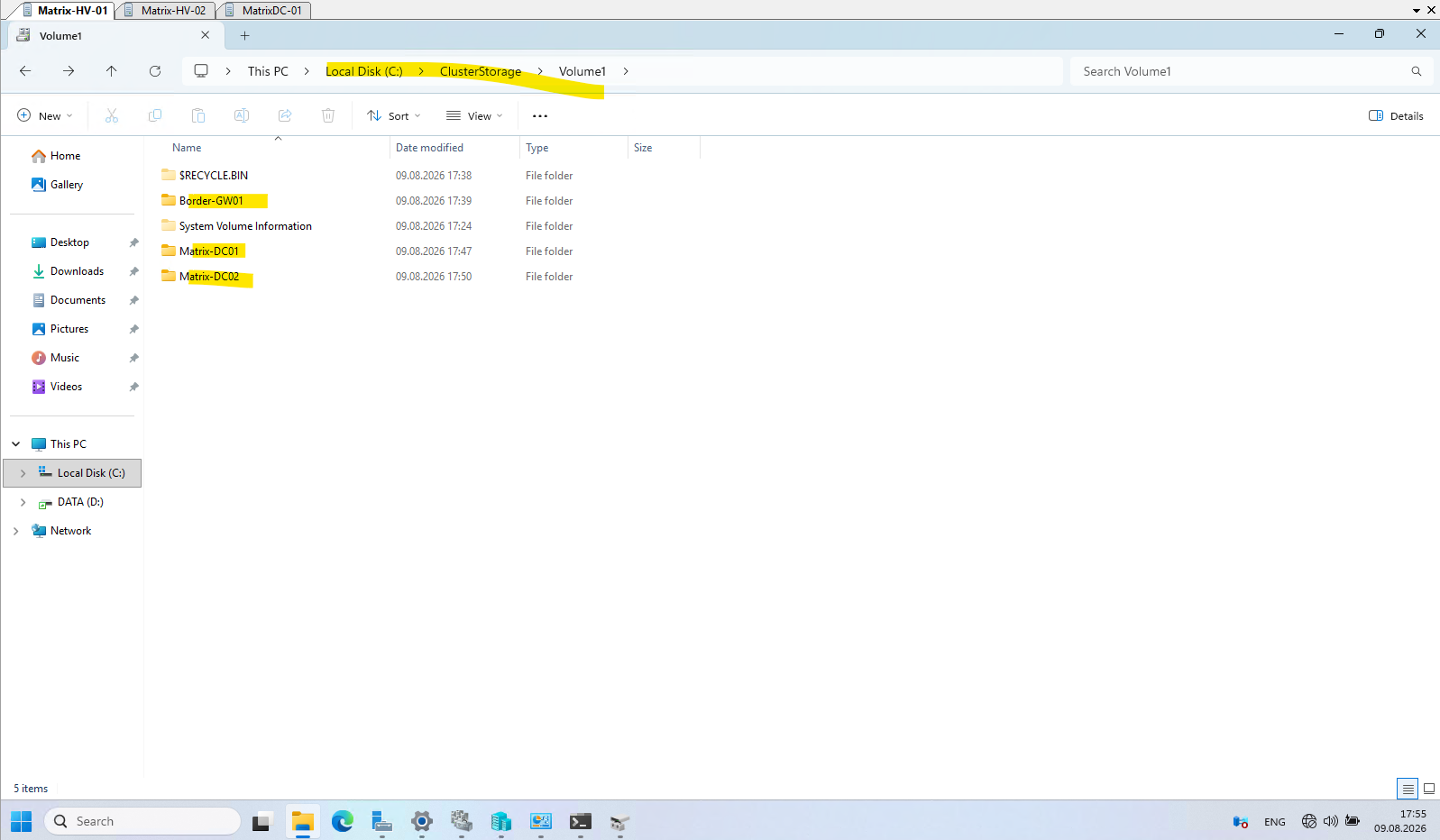
After moving all three virtual machines, we can verify that each VM now has its own dedicated folder on the Cluster Shared Volume under C:\ClusterStorage\Volume1.
The VM files are therefore no longer stored on the individual Hyper-V hosts and are accessible to both cluster nodes, which is a prerequisite for making the VMs highly available.
Configuring the Virtual Machines as Highly Available Cluster Roles
Now that the virtual machine files have been moved to the Cluster Shared Volume (CSV), we can add the VMs to the Failover Cluster and configure them for high availability.
This registers each VM as a clustered role, allowing Failover Clustering to manage its ownership, move it between the Hyper-V nodes, and automatically restart it on another available node if the current owner node fails.
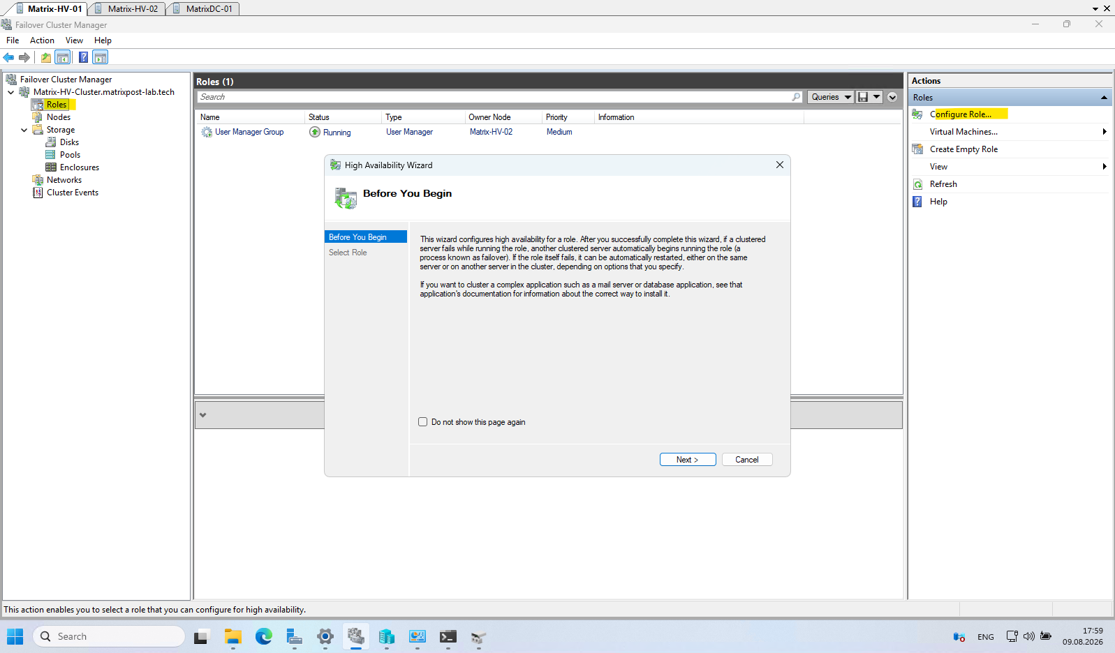
In Failover Cluster Manager, navigate to Roles and click Configure Role in the Actions pane.
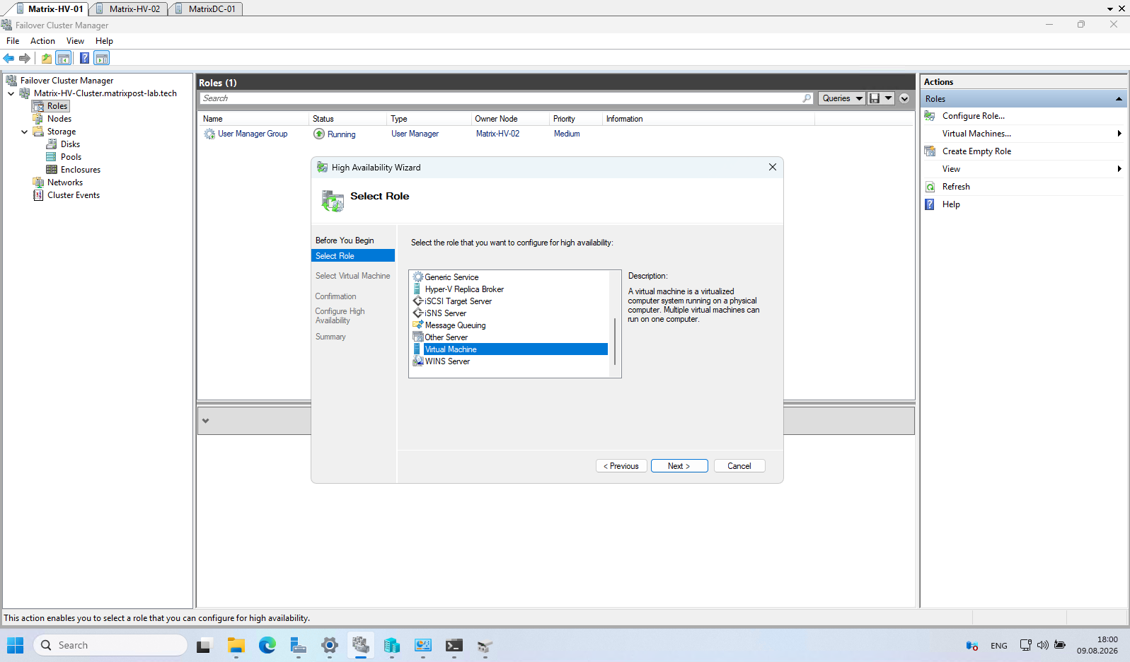
This launches the High Availability Wizard, which we will use to register our existing Hyper-V virtual machines as highly available clustered roles.
In the Select Role step of the High Availability Wizard, select Virtual Machine as the role to configure for high availability.
Click Next to discover the existing Hyper-V VMs on the cluster nodes that can be added as clustered roles.
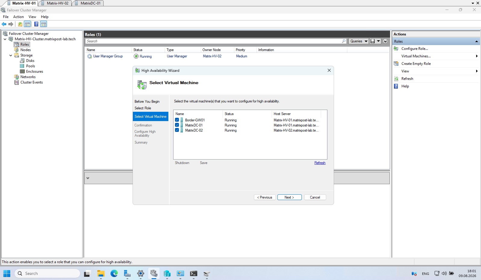
The wizard now lists all existing Hyper-V virtual machines that are eligible to be configured for high availability, including the Host Server on which each VM is currently running.
Select our three VMs Border-GW01, MatrixDC-01, and MatrixDC-02, and click Next.
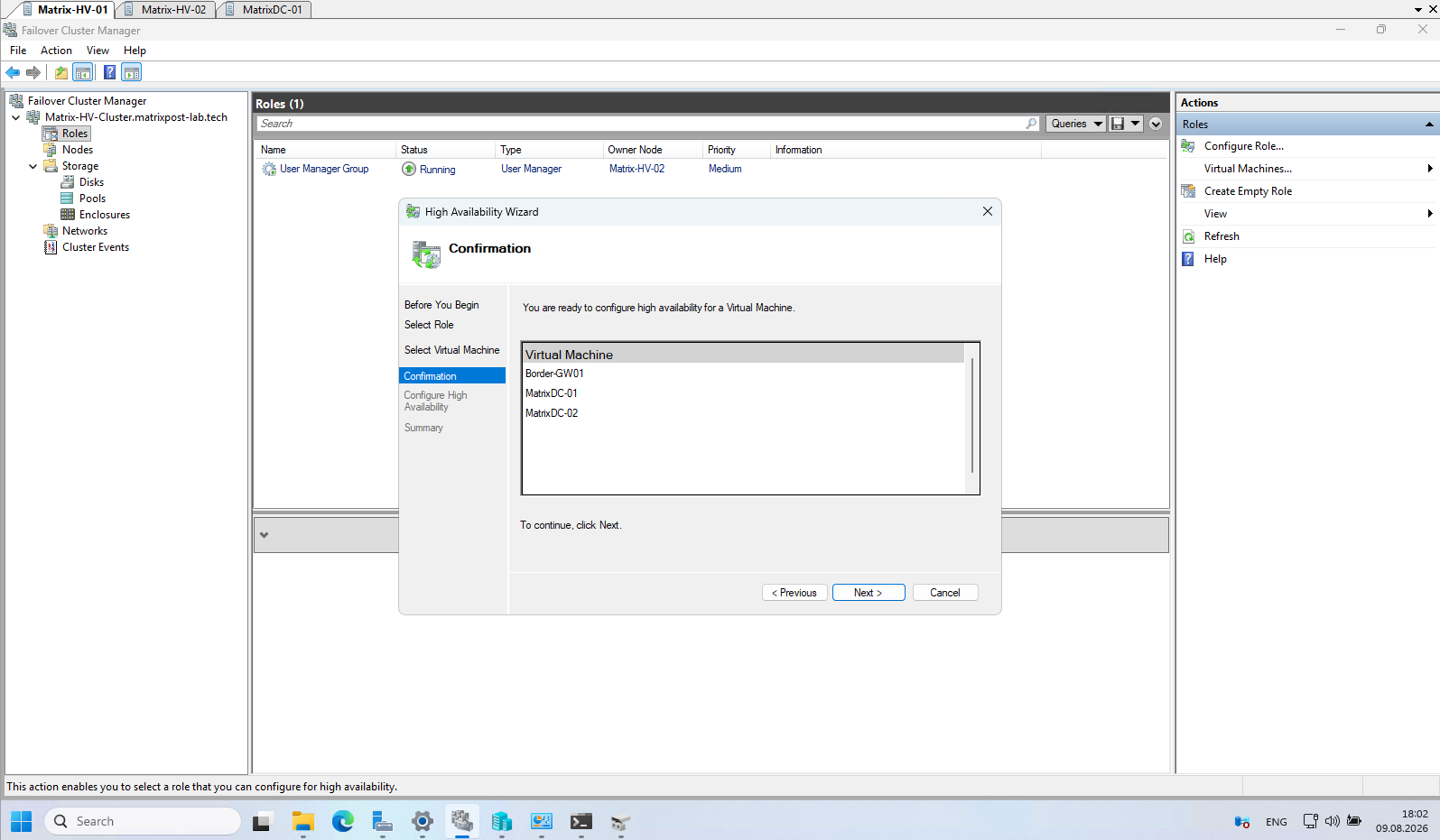
After confirming the selection, the High Availability Wizard starts configuring the selected virtual machines as clustered roles.
During this process, Failover Clustering verifies the required dependencies and registers each VM with the cluster, making it manageable through Failover Cluster Manager and eligible for automatic failover between the Hyper-V nodes.
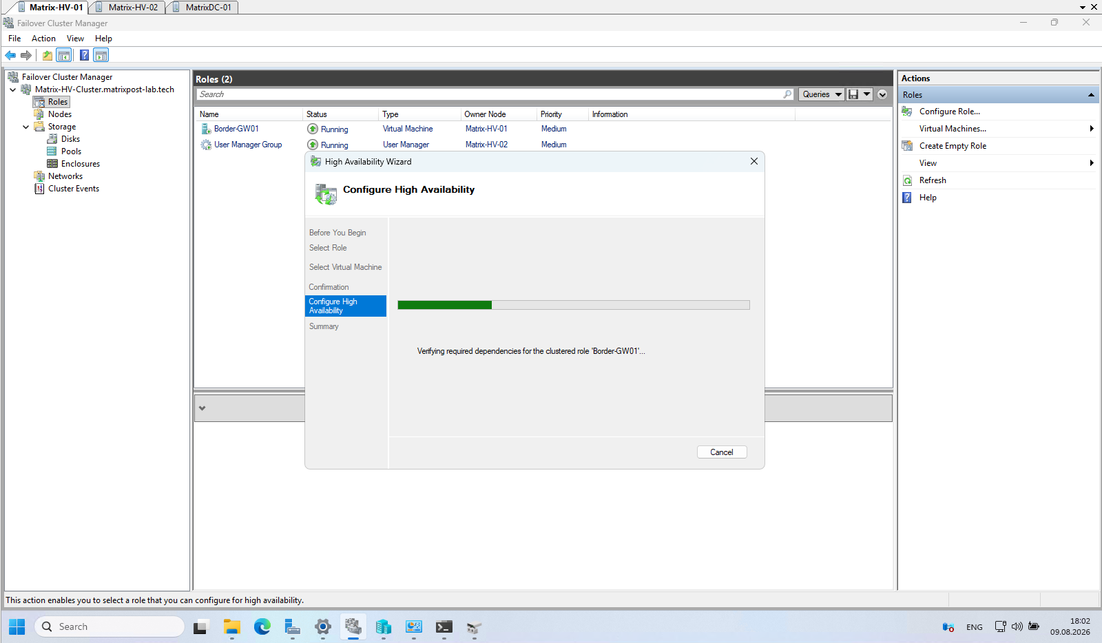
The Summary page confirms that high availability was successfully configured for all three virtual machines. Border-GW01, MatrixDC-01, and MatrixDC-02 are now registered as clustered virtual machine roles and appear under Roles in Failover Cluster Manager, where the cluster can monitor and automatically fail them over to another available Hyper-V node if required.
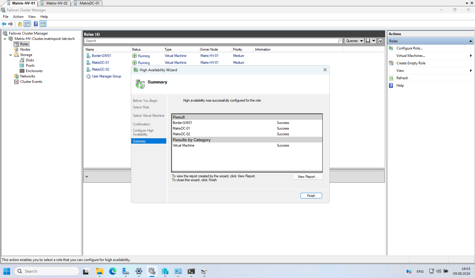
Besides our three highly available virtual machines, Failover Cluster Manager also displays the automatically created User Manager Group. This is an internal cluster system role and is not related to our virtual machines, so no configuration is required.
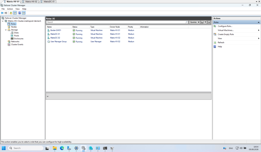
Testing Automatic Failover of a Highly Available Virtual Machine
Now that our virtual machines are stored on the Cluster Shared Volume (CSV) and configured as highly available cluster roles, we can finally test whether failover works as expected.
For this test, we will deliberately reboot one of our Hyper-V cluster nodes while it is hosting running virtual machines. The Failover Cluster should detect that the node becomes unavailable and automatically restart the affected virtual machines on the remaining node, demonstrating that the workloads are protected against a complete host failure.
This also gives us a good opportunity to observe the VM role status, ownership changes, and recovery process directly in Failover Cluster Manager.
For our failover test, I am connected via RDP to MatrixDC-01, which is currently running on Matrix-HV-01.
While keeping the RDP session open, we will reboot Matrix-HV-01 and observe whether the session is interrupted and how quickly MatrixDC-01 is automatically restarted on Matrix-HV-02 by the Failover Cluster.
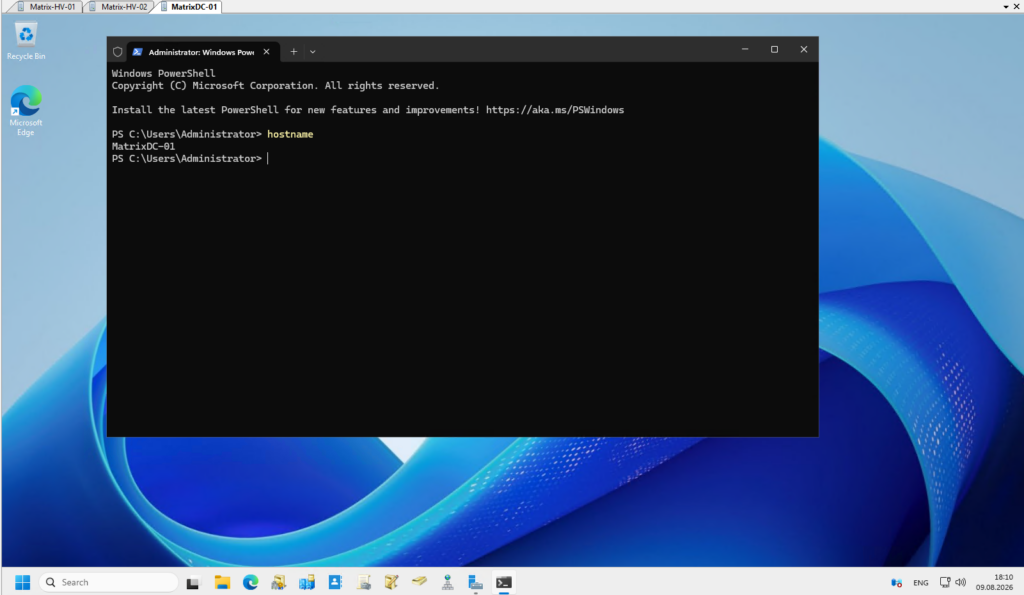
The screenshot shows the starting point of our failover test. Matrix-HV-01 currently hosts the running MatrixDC-01 and Border-GW01 virtual machines. While maintaining the active RDP session to MatrixDC-01, we now restart Matrix-HV-01 to simulate the loss of the Hyper-V host and observe how the Failover Cluster reacts.
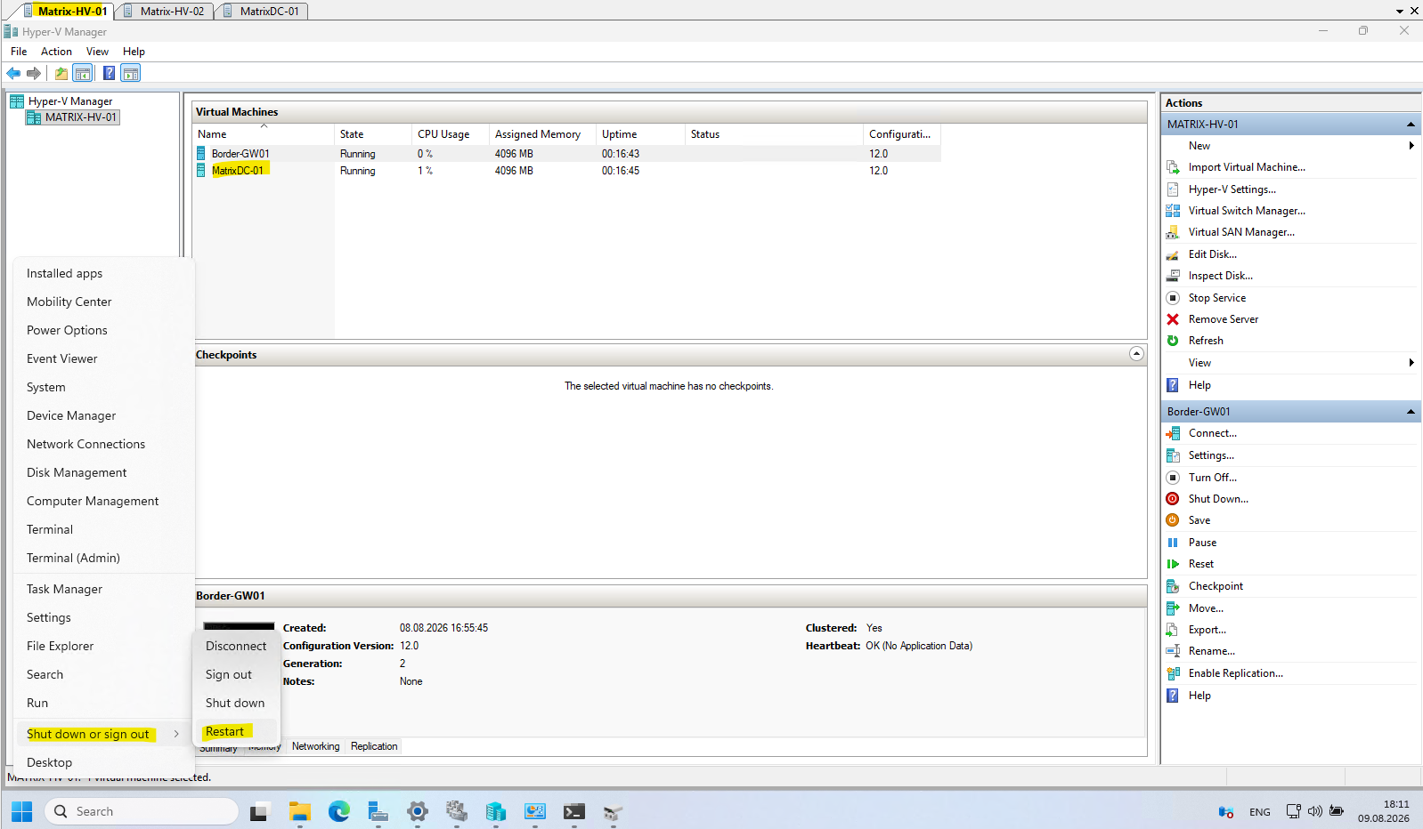
Because we initiated a normal restart of Matrix-HV-01, the Failover Cluster treats the shutdown as planned and automatically live migrates its highly available virtual machines to the remaining cluster node before the host is rebooted. In our case, MatrixDC-01 is already being live migrated to Matrix-HV-02, while Border-GW01 is waiting in the migration queue.
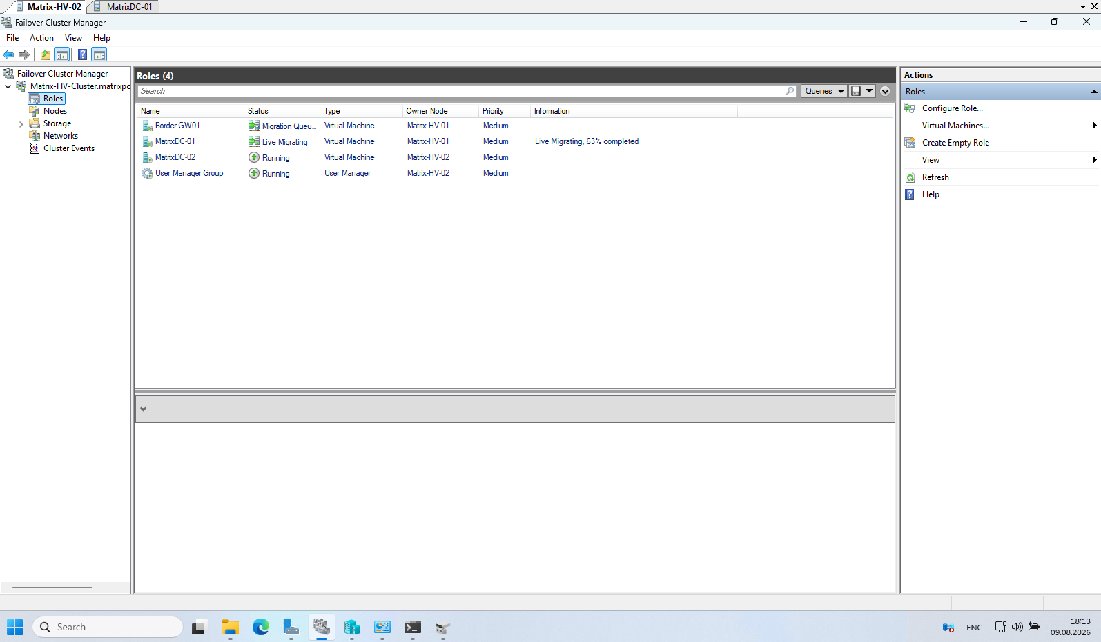
The live migration of MatrixDC-01 completed successfully and the existing RDP session remained connected throughout the migration, demonstrating that planned maintenance of a Hyper-V cluster node can be performed without interrupting the workload.
Border-GW01, our pfSense virtual machine, however, failed to migrate and requires some additional troubleshooting.
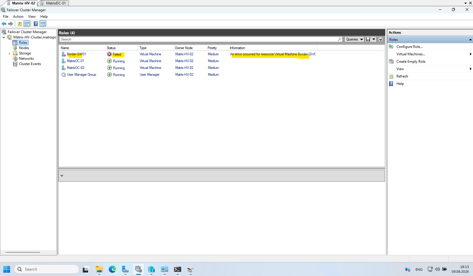
Border-GW01 actually made it to Matrix-HV-02, but it is now in the Saved state. So the cluster successfully transferred ownership to Node 2, but it could not bring the pfSense VM back into the Running state.
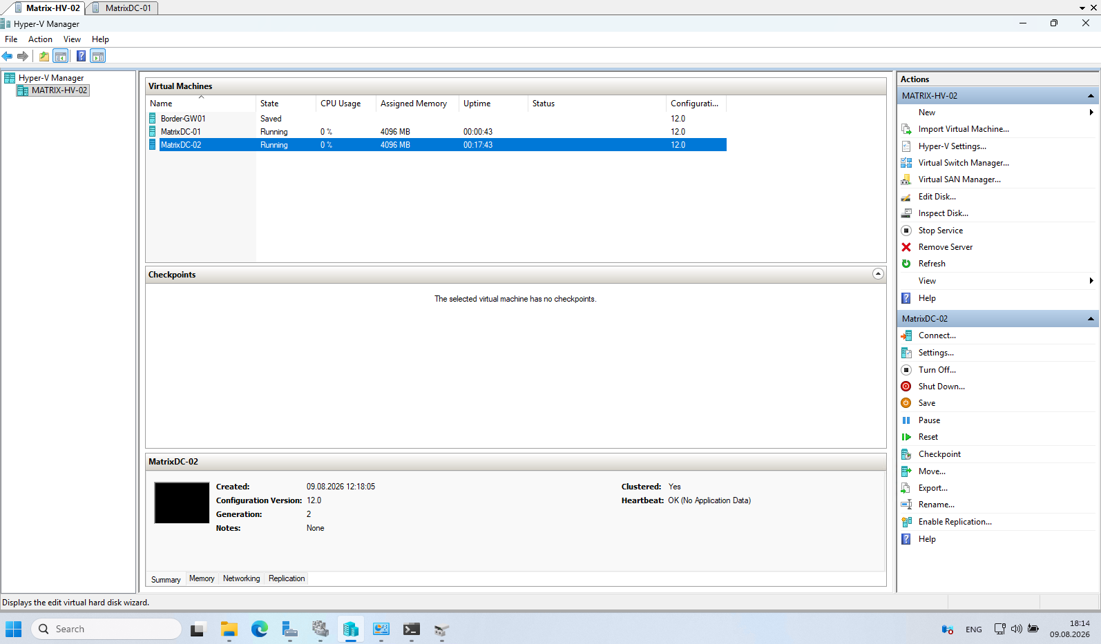
If a VM migration or failover does not complete successfully, we can investigate the issue directly in Failover Cluster Manager → Cluster Events shown below.
The cluster event logs provide detailed information about failed migrations, resource failures, and the underlying error codes.
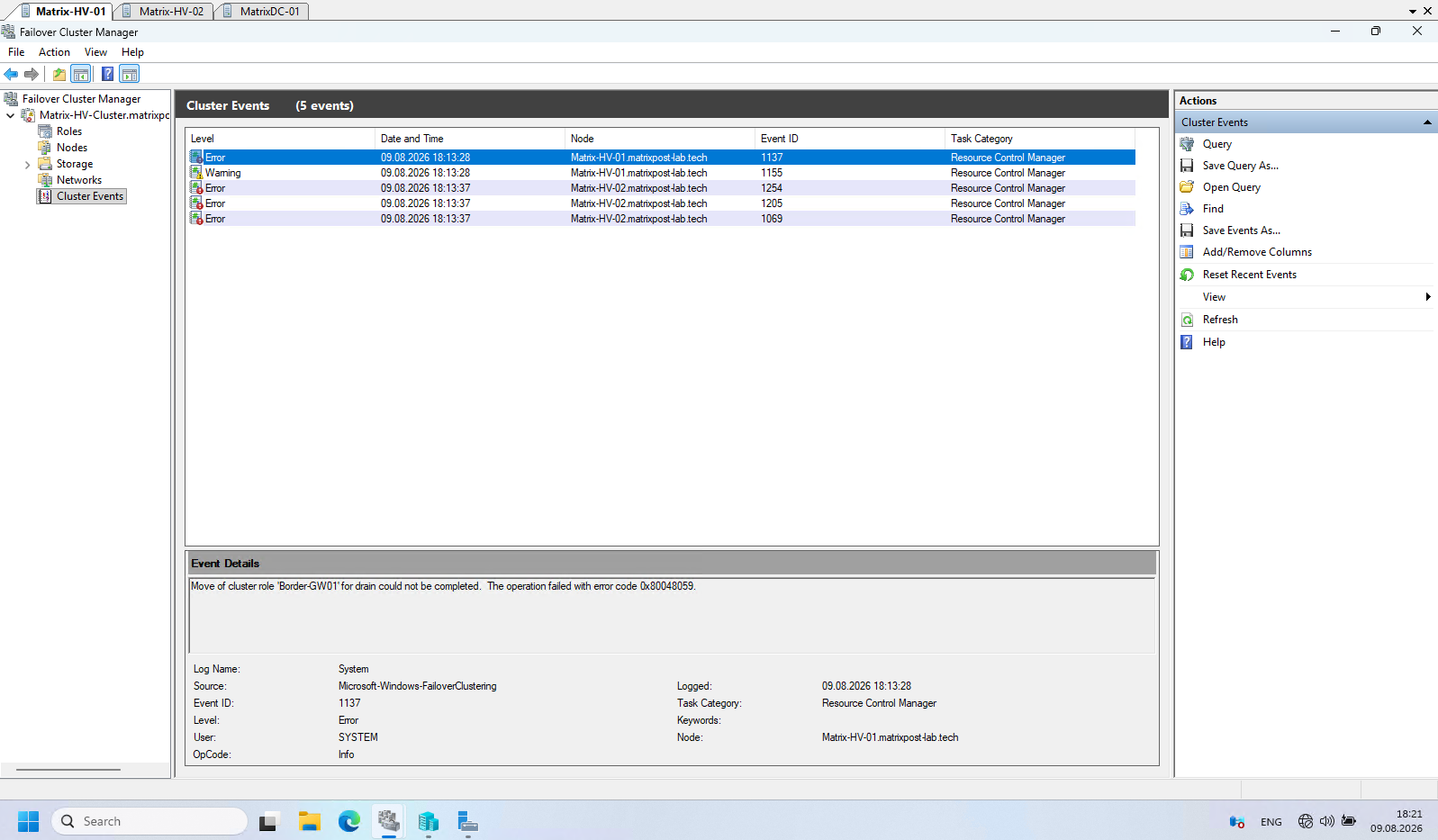
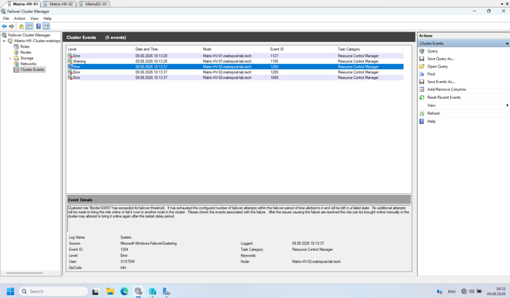
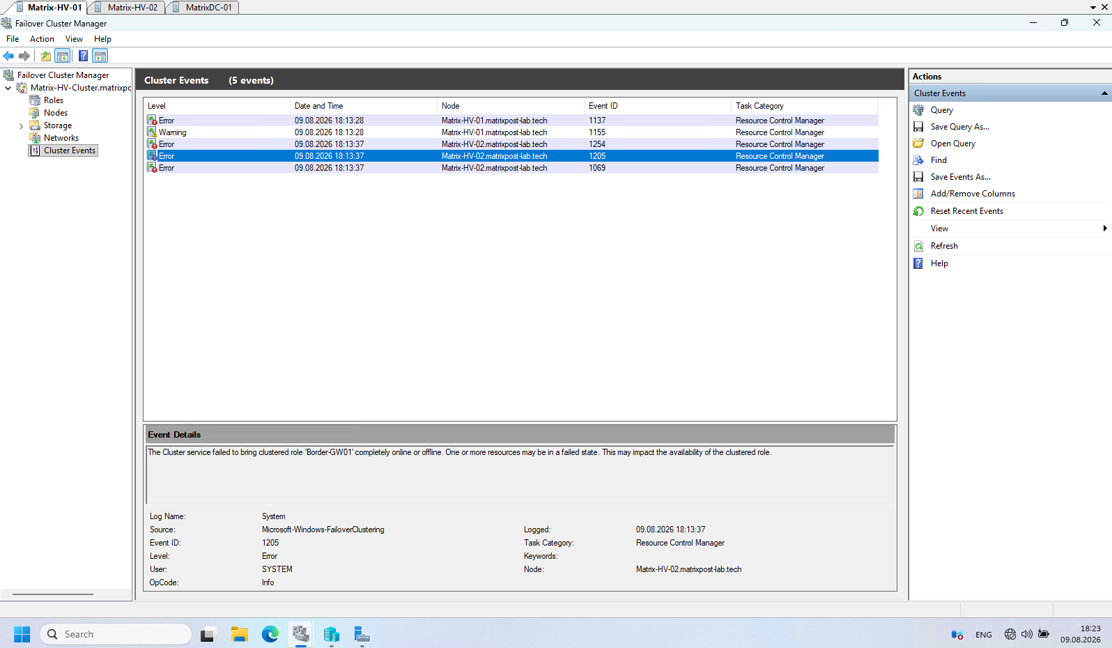
Cluster resource ‘Virtual Machine Border-GW01’ … failed. The error code was ‘0xe’ (‘Not enough memory resources are available to complete this operation.’).
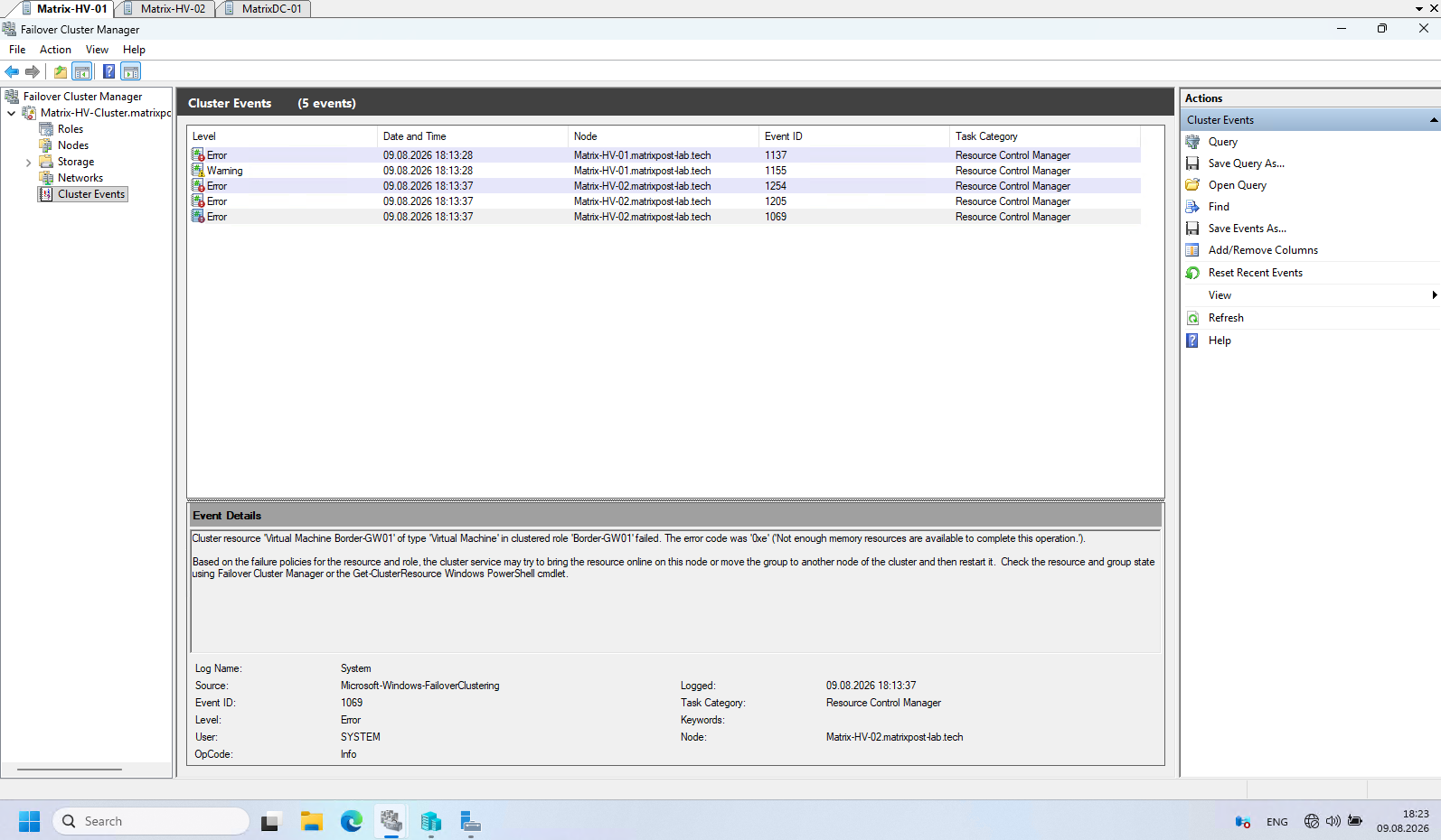
The Border-GW01 (pfSense) VM failed to come online on the remaining cluster node Matrix-HV-02.
Checking the Cluster Events revealed Event ID 1069 with error 0xE – “Not enough memory resources are available to complete this operation.”
Therefore, the failover itself worked as expected, but the target host did not have sufficient memory available to start the pfSense VM.
In my lab, this is simply a resource limitation of the physical Hyper-V hosts. Matrix-HV-01 has 32 GB of RAM, while Matrix-HV-02 has only 16 GB.
In fact, even the Dell XPS notebooks used for my vSphere lab have more memory than these Hyper-V nodes. Therefore, after moving the other workloads to Matrix-HV-02, there was not enough memory available to also start the Border-GW01 (pfSense) VM.
In Part 4, we will deploy and explore System Center Virtual Machine Manager (SCVMM) for centralized management of our Hyper-V environment and compare its architecture, features, and management experience with VMware vCenter.
We will also compare SCVMM with VMware vCenter, looking at how both platforms approach centralized virtualization and cluster management.
Links
Plan for Hyper-V networking in Windows Server
https://learn.microsoft.com/en-us/windows-server/virtualization/hyper-v/plan/plan-hyper-v-networking-in-windows-serverHyper-V Virtual Switch
https://learn.microsoft.com/en-us/windows-server/virtualization/hyper-v/virtual-switchNetwork recommendations for Hyper-V in a failover cluster
https://learn.microsoft.com/en-us/windows-server/virtualization/hyper-v/failover-cluster-network-recommendationsSwitch Embedded Teaming (SET)
https://learn.microsoft.com/en-us/azure/azure-local/concepts/host-network-requirements/#switch-embedded-teaming-setHyper-V virtualization in Windows Server and Windows
https://learn.microsoft.com/en-us/windows-server/virtualization/hyper-v/overviewHyper-V Architecture
https://learn.microsoft.com/en-us/windows-server/virtualization/hyper-v/architecturePlan for Hyper-V security in Windows Server
https://learn.microsoft.com/en-us/windows-server/virtualization/hyper-v/plan/plan-hyper-v-security-in-windows-serverInstall Hyper-V
https://learn.microsoft.com/en-us/windows-server/virtualization/hyper-v/get-started/install-hyper-vWhat is Nested Virtualization?
https://learn.microsoft.com/en-us/windows-server/virtualization/hyper-v/nested-virtualizationHyper-V Virtual Fibre Channel
https://learn.microsoft.com/en-us/windows-server/virtualization/hyper-v/plan/virtual-fibre-channel-for-hyper-vGuarded fabric and shielded VMs
https://learn.microsoft.com/en-us/windows-server/security/guarded-fabric-shielded-vm/guarded-fabric-and-shielded-vms-top-node