Microsoft Hyper-V Networking Best Practices – Part 2 – Configuring Hyper-V Networking, SET, and Failover Clustering
In Part 1 of this series, we installed the Hyper-V role and prepared the lab environment by deploying a domain controller and a pfSense firewall appliance.
In this second part, we will configure the final Hyper-V networking according to Microsoft best practices, including Switch Embedded Teaming (SET), redundant management and VM networks, and finally create our two-node Hyper-V Failover Cluster.
In Part 3, we will extend the cluster with shared iSCSI storage, configure a Cluster Shared Volume (CSV), migrate our existing virtual machines to shared storage, make them highly available clustered VMs, and test Live Migration and automatic failover.
In Part 4, we will deploy and explore System Center Virtual Machine Manager (SCVMM) for centralized management of our Hyper-V environment and compare its architecture, features, and management experience with VMware vCenter.
Configure the Network Adapters
For a highly available Hyper-V host, the physical network connections should be distributed across redundant physical switches to avoid a single point of failure. In this design, two physical network adapters are dedicated to host management, while another two adapters are dedicated to virtual machine traffic and will later form the Switch Embedded Team (SET).
MGMT-A and MGMT-B provide redundant connectivity for the Hyper-V management operating system and are connected to different physical switches.
VM-A and VM-B are also connected to different switches and will be combined into a Switch Embedded Team (SET), providing redundant and load-balanced uplink connectivity for the Hyper-V virtual switch.
            ToR-A                 ToR-B
              |                     |
         MGMT-A                 MGMT-B
              \                 /
               \               /
                  Matrix-HV-01

         VM-A                  VM-B
              \               /
               \             /
Before configuring the final Hyper-V networking, it is useful to document the current physical adapter mapping and their intended roles.
The following table shows the network adapters on Matrix-HV-01, their physical switch configuration, current usage, and their final purpose in the Hyper-V network design.
| Current adapter | Physical switch configuration | Current purpose | Final purpose |
|---|---|---|---|
Ethernet 2 | Access VLAN 10 | Management 10.0.0.50 | MGMT-A |
Ethernet 7 | Access VLAN 10 | — | MGMT-B |
Ethernet 6 | Trunk VLAN 10/20/100 | vSwitch-temp-vms | VM-A |
Ethernet 8 | Trunk VLAN 10/20/100 | — | VM-B |
First I will rename the adapter:
Rename-NetAdapter -Name "Ethernet 2" -NewName "MGMT-A"
Rename-NetAdapter -Name "Ethernet 7" -NewName "MGMT-B"
Rename-NetAdapter -Name "Ethernet 6" -NewName "VM-A"
Rename-NetAdapter -Name "Ethernet 8" -NewName "VM-B"
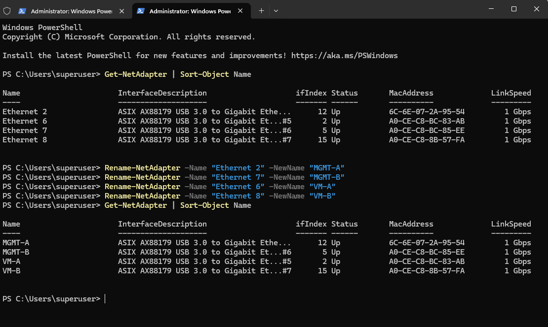
Because MGMT-A and MGMT-B are connected to access ports in VLAN 10, there is no need for VLAN tagging on the Hyper-V host itself. The physical switches handle that.
             VLAN 10                     VLAN 10
              Access                      Access
                |                           |
             MGMT-A                      MGMT-B
                |                           |
          10.0.0.50                     unused
Creating the SET Virtual Switch for Management Traffic
For the final configuration, we use a management SET:
             ToR-A                       ToR-B
              |                           |
        Access VLAN 10              Access VLAN 10
              |                           |
           MGMT-A                       MGMT-B
               \                         /
                \                       /
                  vSwitch-MGMT
                       |
                 vEthernet (MGMT)
                       |
                  10.0.0.50
Because both physical switch ports are access VLAN 10, we don’t need to configure VLAN 10 on the Hyper-V management vNIC either. Everything remains untagged from the host’s perspective.
When creating the management SET (Switch Embedded Teaming), the physical adapters MGMT-A and MGMT-B become uplinks of the Hyper-V virtual switch. The host’s management IP configuration is therefore moved from the physical adapter to the newly created Hyper-V management vNIC.
Create:
New-VMSwitch `
    -Name "vSwitch-MGMT" `
    -NetAdapterName "MGMT-A","MGMT-B" `
    -EnableEmbeddedTeaming $true `
    -AllowManagementOS $true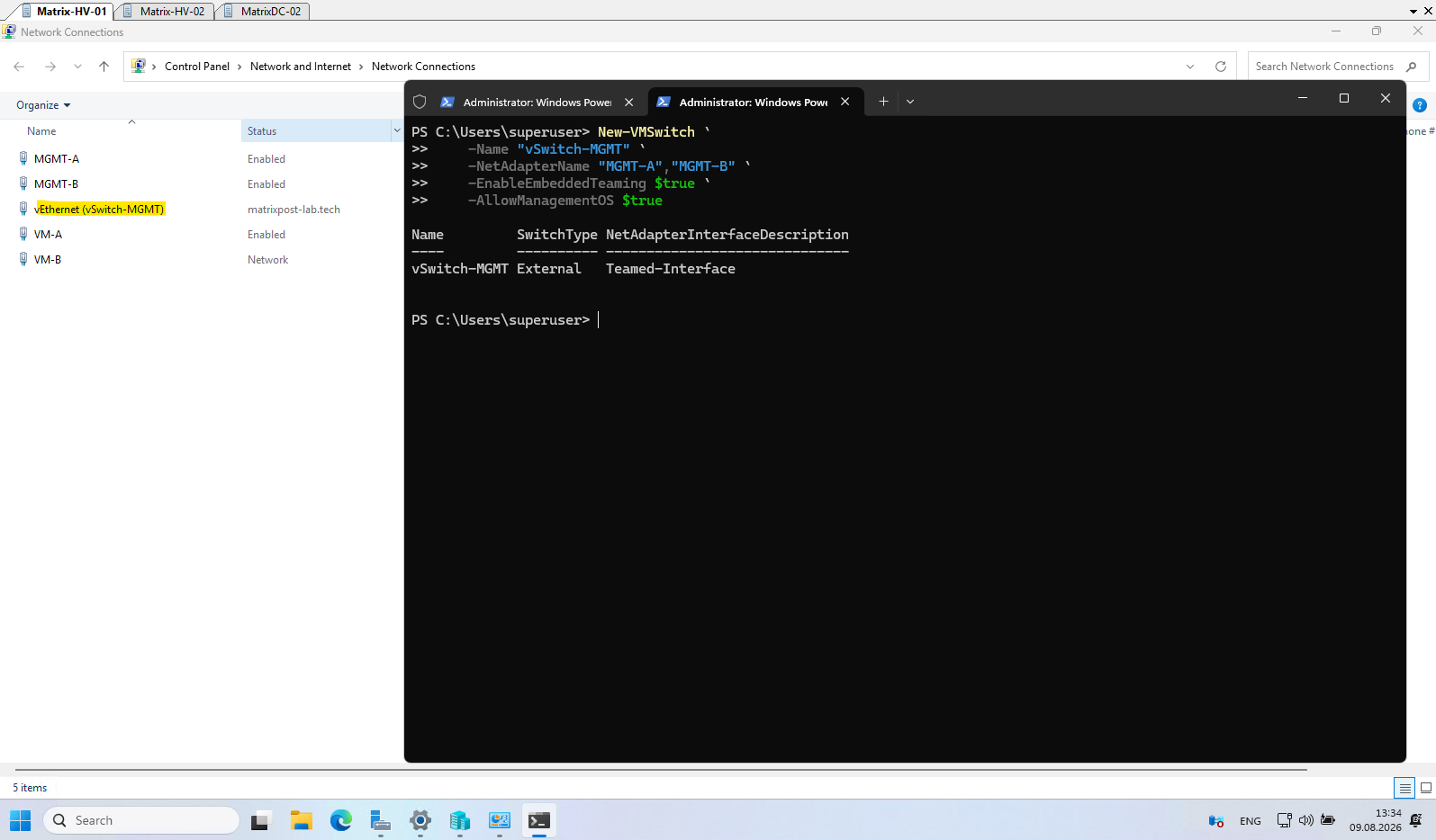
After creating vSwitch-MGMT, Hyper-V automatically created the management operating system vNIC vEthernet (vSwitch-MGMT) and transferred the existing management network configuration to it.
The host therefore keeps its original management address 10.0.0.50, default gateway 10.0.0.1, and DNS servers 10.0.0.70/10.0.0.71, while MGMT-A and MGMT-B now act only as physical uplinks for the SET switch.
Get-NetAdapter
Get-NetIPConfiguration
Get-VMNetworkAdapter -ManagementOS
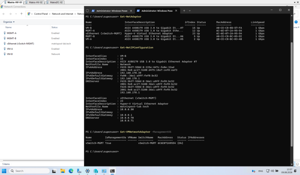
When Hyper-V creates the external switch, it creates a virtual NIC for the management OS. Because MGMT-A previously carried the host’s IP configuration, Windows migrates that TCP/IP configuration from the physical adapter to the newly created management vNIC.
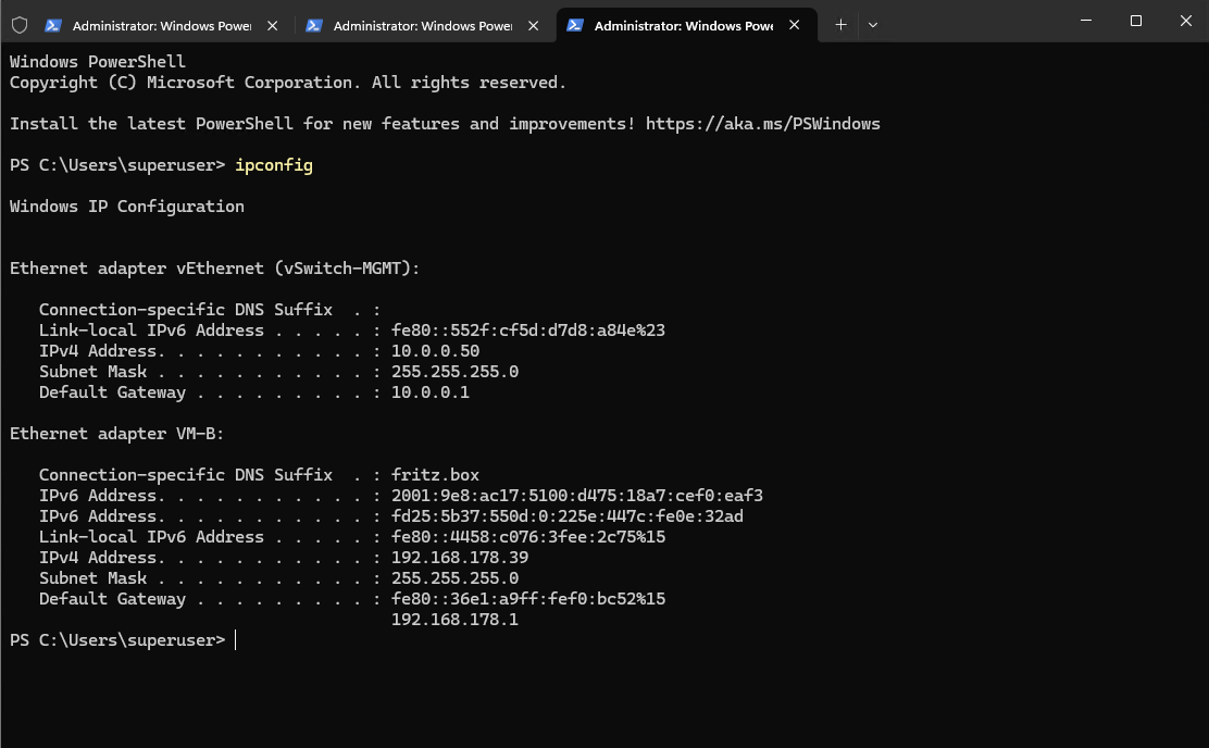
We can verify the result with ipconfig. As shown below, the host’s management IP configuration is now assigned to the vEthernet (vSwitch-MGMT) adapter created by Hyper-V.
By specifying
-EnableEmbeddedTeaming $true, the two physical management adapters are combined directly within the Hyper-V virtual switch using Switch Embedded Teaming (SET).With
-AllowManagementOS $true, Hyper-V additionally creates a management OS vNIC and automatically transfers the existing host IP configuration from the physical management adapter to this virtual adapter.
PS> ipconfig
Creating the SET Virtual Switch for VM Traffic
The physical adapters VM-A and VM-B are connected to trunk ports on separate physical switches and will now be combined into a second Switch Embedded Team (SET). This SET is dedicated exclusively to virtual machine traffic and carries the required VLANs across both redundant physical uplinks.
Before changing the configuration, we can verify the current VM network connections and VLAN assignments:
Get-VMNetworkAdapter -VMName *
Get-VMNetworkAdapterVlan -VMName *
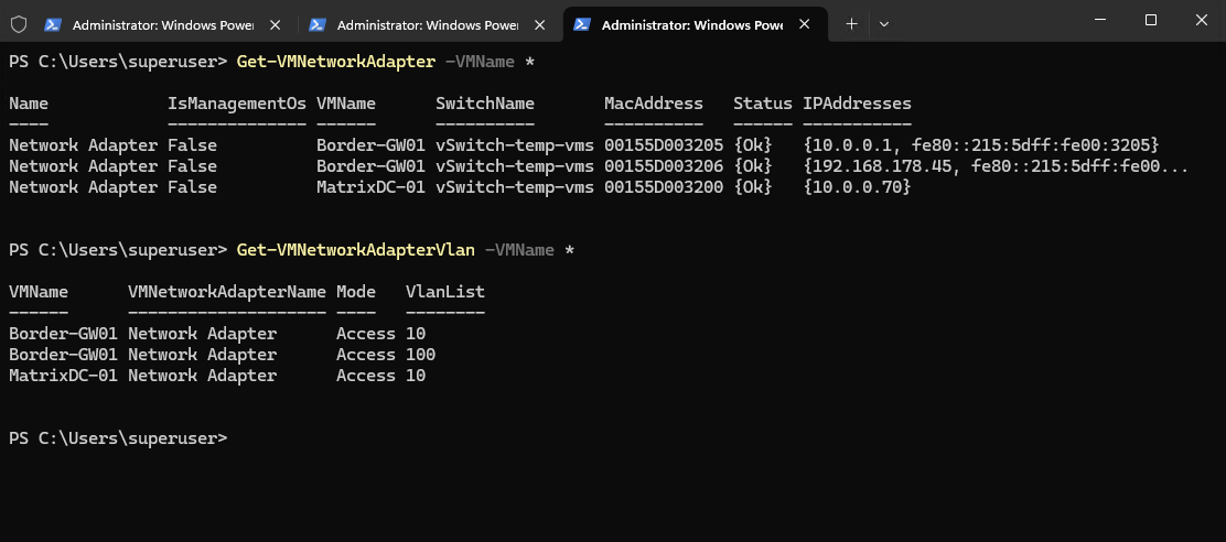
In our lab, the current VLAN configuration is:
Border-GW01    Network Adapter    Access    10
Border-GW01    Network Adapter    Access    100
MatrixDC-01    Network Adapter    Access    10
This is important because the same VLAN assignments need to be restored after replacing the temporary virtual switch.
Because vSwitch-temp-vms is currently used by both the domain controller and pfSense appliance, shut them down before removing the temporary switch:
Stop-VM -Name "Border-GW01","MatrixDC-01"
VM-A is currently used as the physical uplink of vSwitch-temp-vms. Therefore, the temporary switch must first be removed to release the adapter:
Remove-VMSwitch -Name "vSwitch-temp-vms"
Verify that both physical adapters are available:
Get-NetAdapter -Name "VM-A","VM-B"
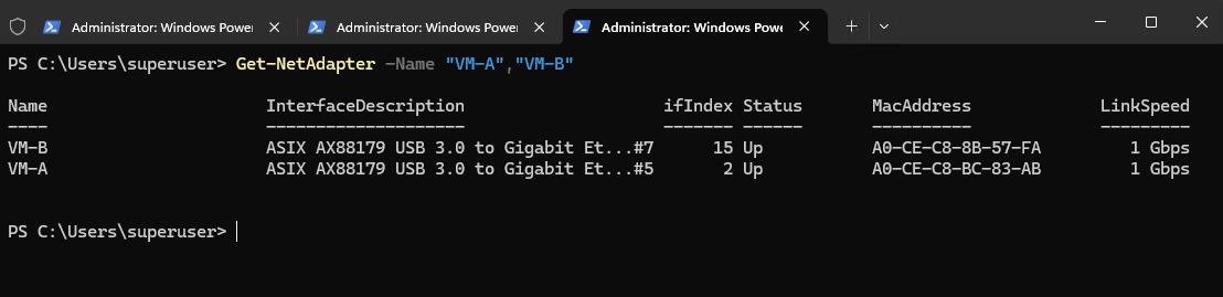
Now combine VM-A and VM-B into the final SET-based Hyper-V virtual switch:
New-VMSwitch `
    -Name "vSwitch-VM" `
    -NetAdapterName "VM-A","VM-B" `
    -EnableEmbeddedTeaming $true `
    -AllowManagementOS $false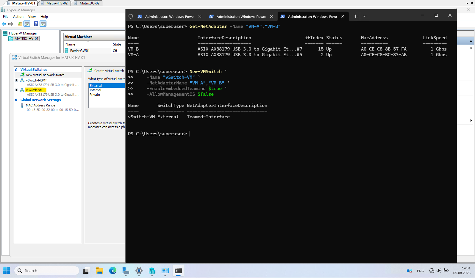
Both physical adapters are connected to 802.1Q trunk ports on separate physical switches, providing redundant physical connectivity while carrying the VLANs required by the virtual machines.
Unlike vSwitch-MGMT, the new vSwitch-VM is dedicated exclusively to virtual machine traffic. Therefore, -AllowManagementOS $false is specified and Hyper-V does not create a management OS vNIC on this switch.
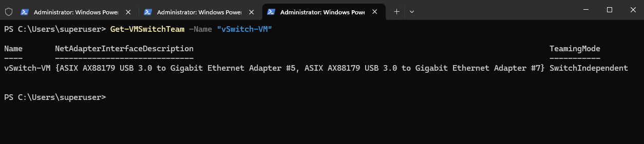
Verify that VM-A and VM-B are members of the new SET (Switch Embedded Team):
As shown below, both physical adapters VM-A and VM-B are members of
vSwitch-VM, and the team operates in SwitchIndependent mode.Unlike traditional NIC Teaming (LBFO), a Switch Embedded Teaming (SET) configuration does not appear as a separate NIC team in the Windows GUI. To verify which physical network adapters are currently members of the SET-enabled Hyper-V virtual switch, we can use the
Get-VMSwitchTeamPowerShell cmdlet. In our case, the output confirms that both VM-A and VM-B are members ofvSwitch-VM.System Center Virtual Machine Manager (SCVMM) provides a much more comprehensive graphical and centralized networking management layer using concepts such as Logical Switches, Logical Networks, Uplink Port Profiles, and VM Networks. We will explore this in more detail in Part 4 of this series.
SwitchIndependent means the physical switches do not need to be aware of or participate in the teaming configuration. Each uplink can therefore be connected to a different physical switch, which provides switch-level redundancy and is ideally suited for our two-ToR design.
Get-VMSwitchTeam -Name "vSwitch-VM"
Also verify both Hyper-V switches:
Get-VMSwitch
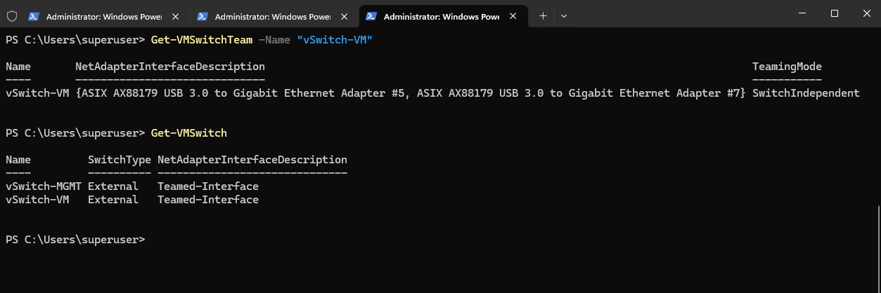
At this point we should have:
vSwitch-MGMT
    |
    +-- MGMT-A
    +-- MGMT-B
    |
    +-- Management OS vNIC
        10.0.0.50

vSwitch-VM
    |
    +-- VM-A
    +-- VM-B
    |
    +-- VM traffic
        VLAN 10 / VLAN 20 / VLAN 100
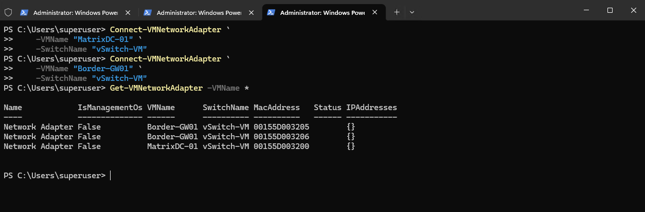
Removing vSwitch-temp-vms does not remove the virtual network adapters from the VMs. Connect them to the new vSwitch-VM:
Connect-VMNetworkAdapter `
    -VMName "MatrixDC-01" `
    -SwitchName "vSwitch-VM"
For pfSense, both virtual adapters need to use the new switch:
Connect-VMNetworkAdapter `
    -VMName "Border-GW01" `
    -SwitchName "vSwitch-VM"
Verify:
Get-VMNetworkAdapter -VMName *
Next we also need to restore the VLAN assignments.
For the domain controller:
Set-VMNetworkAdapterVlan `
    -VMName "MatrixDC-01" `
    -Access `
    -VlanId 10
For pfSense, we have two identically named virtual adapters, so use their MAC addresses to distinguish LAN from WAN.
From my current configuration:
00155D003205 = pfSense LAN = VLAN 10
00155D003206 = pfSense WAN = VLAN 100
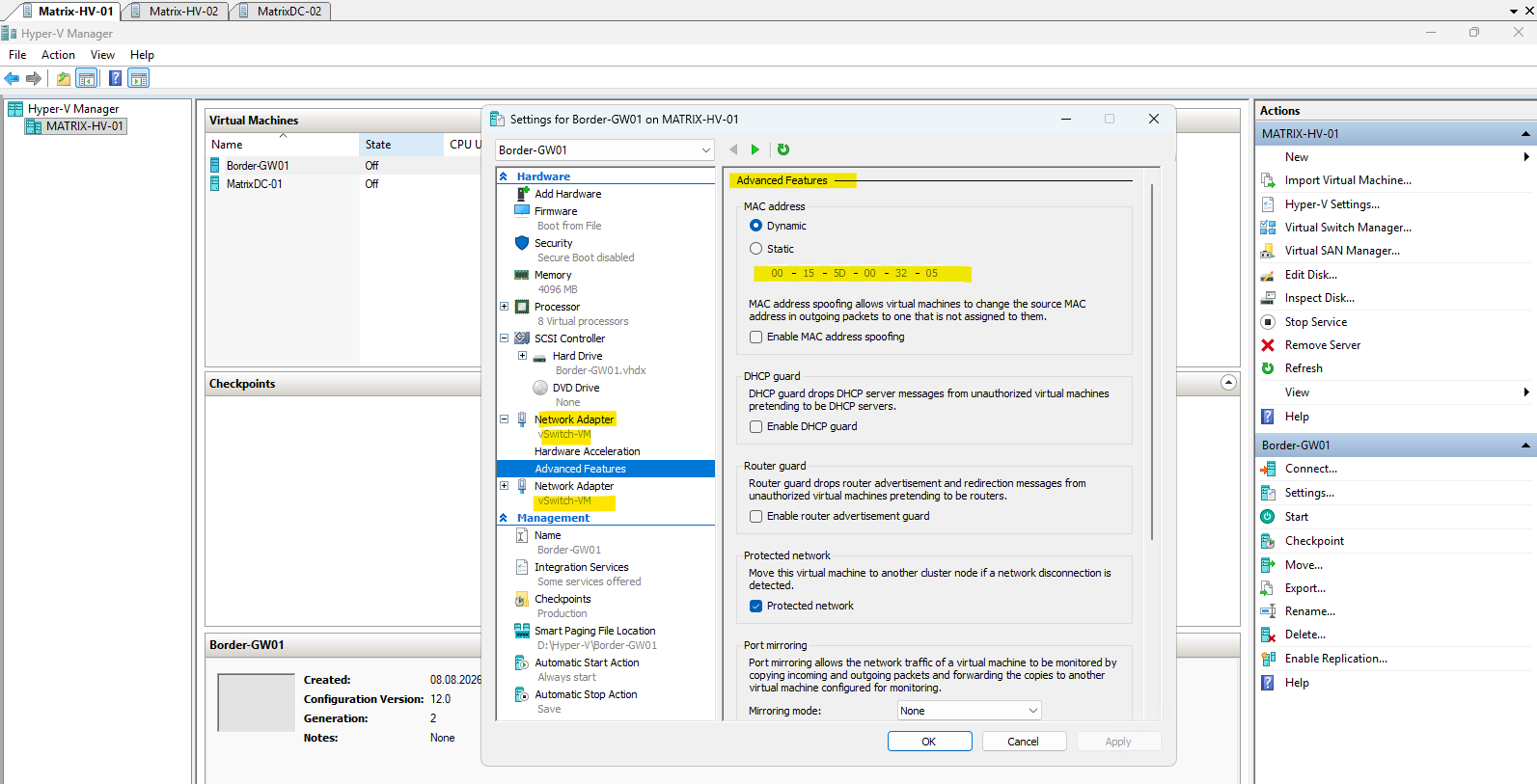
Configure them accordingly:
Get-VMNetworkAdapter -VMName "Border-GW01" |
    Where-Object MacAddress -eq "00155D003205" |
    Set-VMNetworkAdapterVlan -Access -VlanId 10

Get-VMNetworkAdapter -VMName "Border-GW01" |
    Where-Object MacAddress -eq "00155D003206" |
    Set-VMNetworkAdapterVlan -Access -VlanId 100
Verify the result:
Get-VMNetworkAdapterVlan -VMName *

Finally we can start the virtual machines again.
Start-VM -Name "Border-GW01","MatrixDC-01"
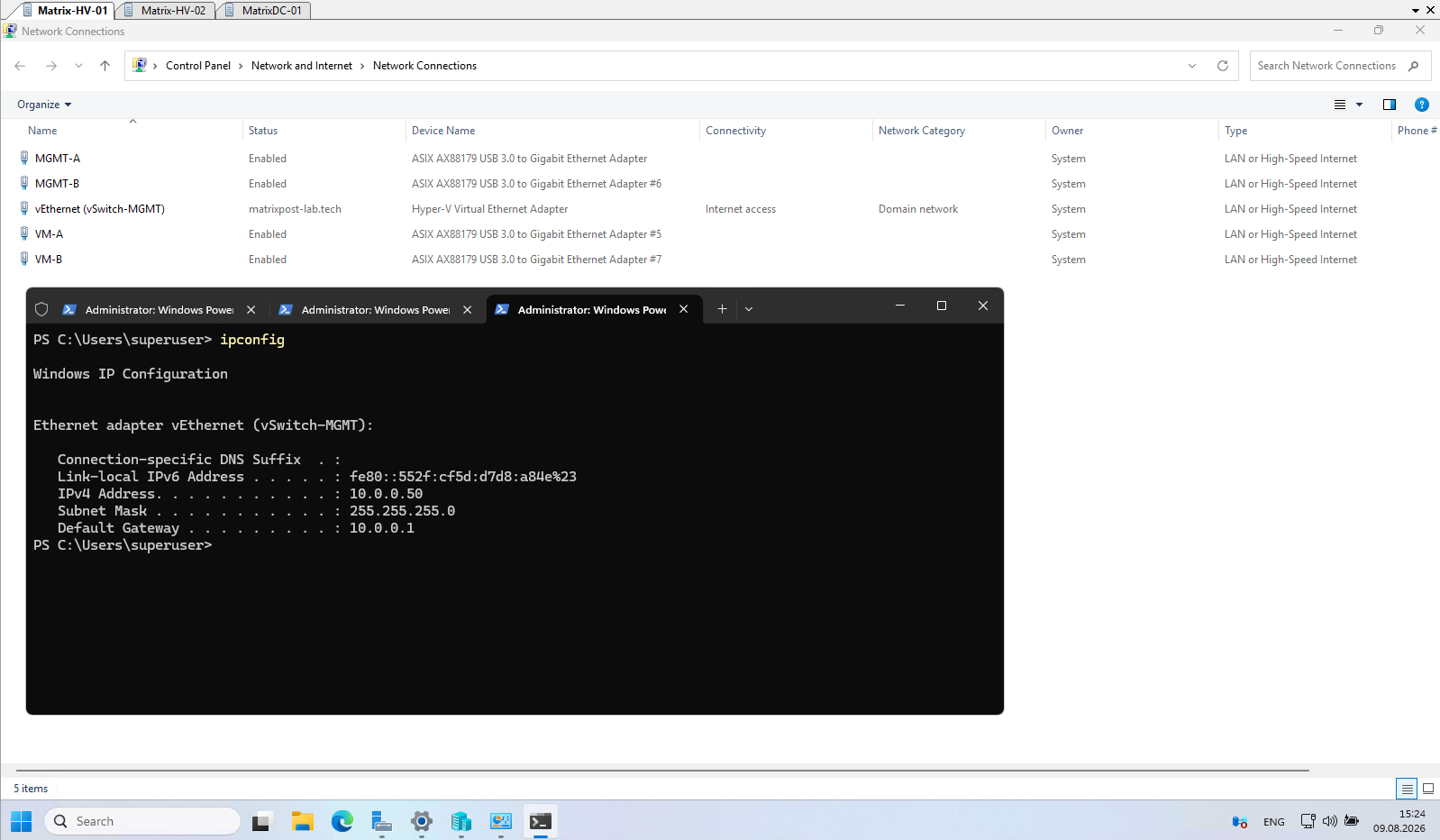
As shown below, physical NICs that are associated with a Hyper-V virtual switch no longer appear in ipconfig, because their host-side IP configuration is removed and Hyper-V takes ownership of the adapters.
The
vEthernet (vSwitch-MGMT)adapter appears because we created the management switch with-AllowManagementOS $true, which creates a management OS vNIC and places the host IP configuration on this virtual adapter;vSwitch-VM, created with-AllowManagementOS $false, therefore has no corresponding host vNIC inipconfig.
The same networking configuration is now applied to the second Hyper-V host, Matrix-HV-02, including the management and VM traffic SET (Switch Embedded Teams) switches.
Once both hosts are configured identically, we can proceed with the next step and install Failover Clustering on both Hyper-V hosts.
Install Failover Clustering
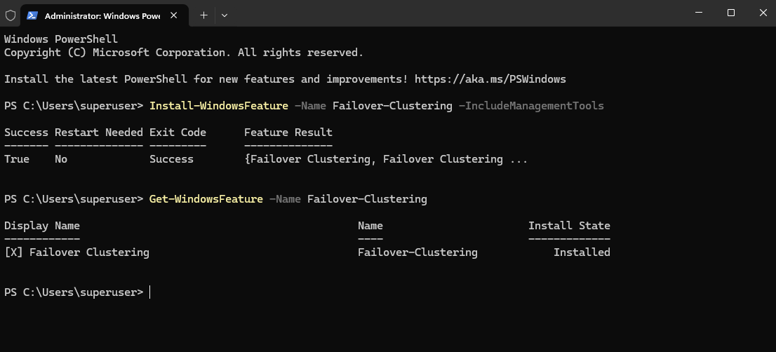
With the network configuration completed on both Hyper-V hosts, we can now install the Failover Clustering feature. This provides the Windows clustering functionality required to combine Matrix-HV-01 and Matrix-HV-02 into a highly available Hyper-V cluster.
For a more detailed walkthrough of creating and configuring a Hyper-V Failover Cluster, you can also read my following post.
The feature must be installed on both Hyper-V hosts. We can install it using Server Manager → Add Roles and Features → Features → Failover Clustering, including the required management tools.
Alternatively, and much quicker for both servers, use PowerShell:
Install-WindowsFeature -Name Failover-Clustering -IncludeManagementTools
After installation, verify that the feature is installed:
Get-WindowsFeature -Name Failover-Clustering
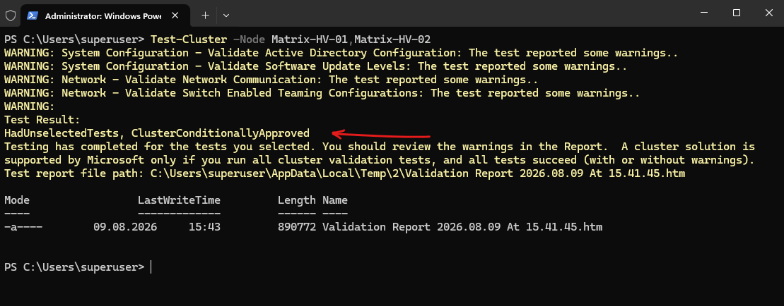
Before actually creating the cluster, Microsoft strongly recommends running the cluster validation tests. These tests verify whether the servers, networking, system configuration, and available storage are suitable for Failover Clustering.
In this example, the configuration is conditionally approved, but several warnings are reported for Active Directory, software update levels, network communication, and the SET configuration, which we will review before proceeding.
Test-Cluster -Node Matrix-HV-01,Matrix-HV-02
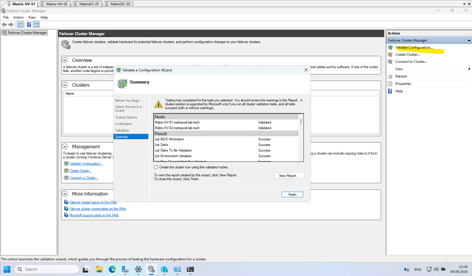
Alternatively, the cluster configuration can also be validated graphically using Failover Cluster Manager → Validate Configuration, which launches the Validate a Configuration Wizard as shown below. The complete GUI-based validation and cluster creation process is also covered in my dedicated Hyper-V Failover Cluster post.
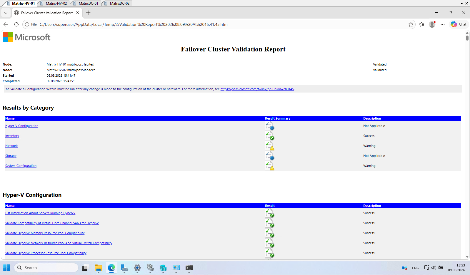
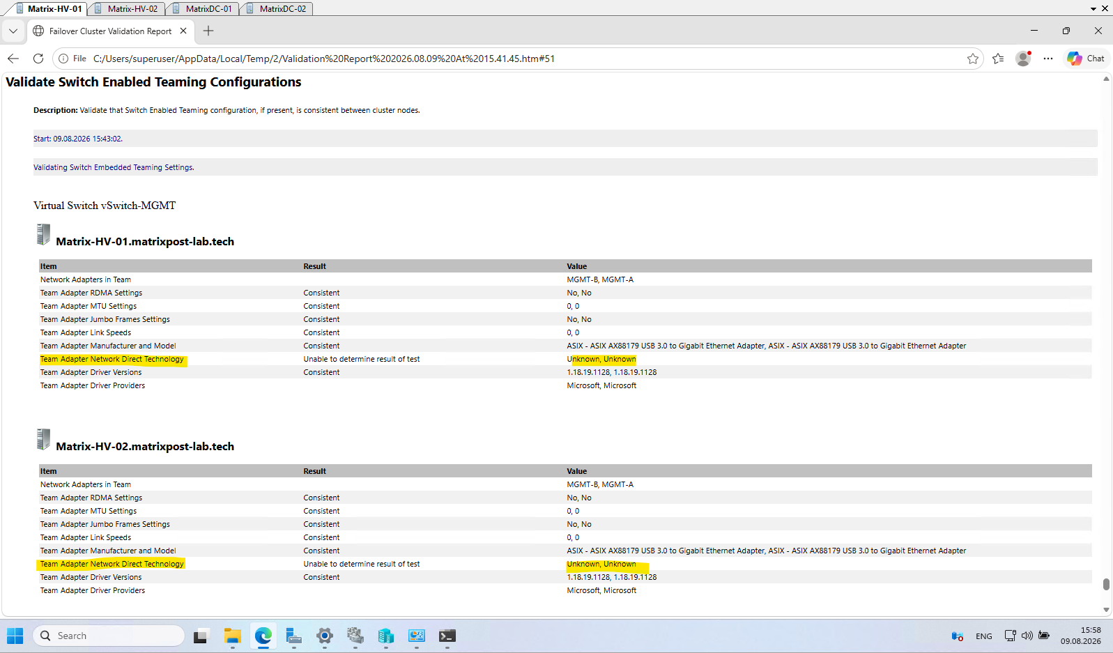
We can inspect the generated HTML validation report for detailed results of each individual cluster test. In our case, the overall configuration is conditionally approved, with the Hyper-V compatibility tests succeeding while a few warnings remain for Active Directory, software update levels, network communication, and the SET configuration.
The warning related to Switch Embedded Teaming (SET) is caused by the validation test being unable to determine the Network Direct/RDMA technology of the teamed adapters.
This is expected in our lab because the ASIX AX88179 USB network adapters do not provide RDMA capabilities and does not indicate a problem with the SET configuration itself.
Network Direct is Microsoft’s implementation of RDMA (Remote Direct Memory Access), which allows data to be transferred directly between the memory of servers with minimal CPU involvement and very low latency. It is primarily used with high-performance server NICs for workloads such as SMB Direct, Storage Spaces Direct (S2D), and cluster storage traffic.
Create the Hyper-V Failover Cluster
After reviewing the validation report and confirming that the remaining warnings are expected or acceptable for our lab environment, we can proceed with creating the Failover Cluster using our two Hyper-V hosts, Matrix-HV-01 and Matrix-HV-02.
The cluster receives its own cluster name and IP address, which are used as the administrative access point for managing the cluster independently of the individual Hyper-V hosts.
Create the cluster from either Hyper-V host:
We use
-NoStoragebecause we don’t want the wizard to automatically add any discovered storage at this point. We can configure the cluster storage deliberately afterward.
New-Cluster `
    -Name "Matrix-HV-Cluster" `
    -Node "Matrix-HV-01","Matrix-HV-02" `
    -StaticAddress 10.0.0.55 `
    -NoStorage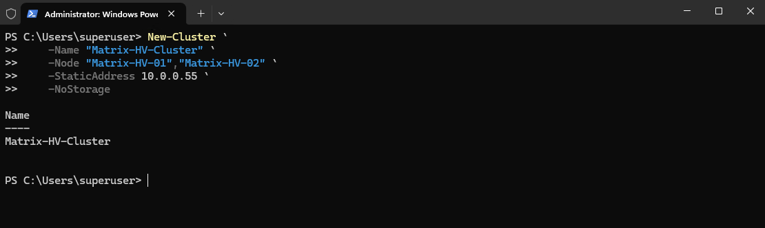
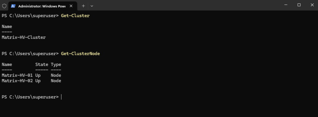
Once creation has completed, verify the new cluster:
Get-Cluster
Get-ClusterNode
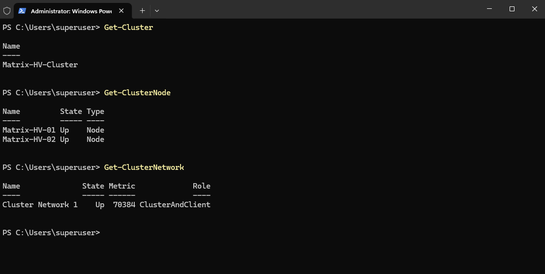
Get-ClusterNetworkshows that the detected cluster network is Up and configured with the ClusterAndClient role, meaning it can be used for both inter-node cluster communication and client connectivity.
After creating the cluster, we can open Failover Cluster Manager and verify that Matrix-HV-Cluster is online and both Hyper-V hosts have been added as cluster nodes. The cluster core resources are also online, confirming that the basic Failover Cluster has been created successfully.
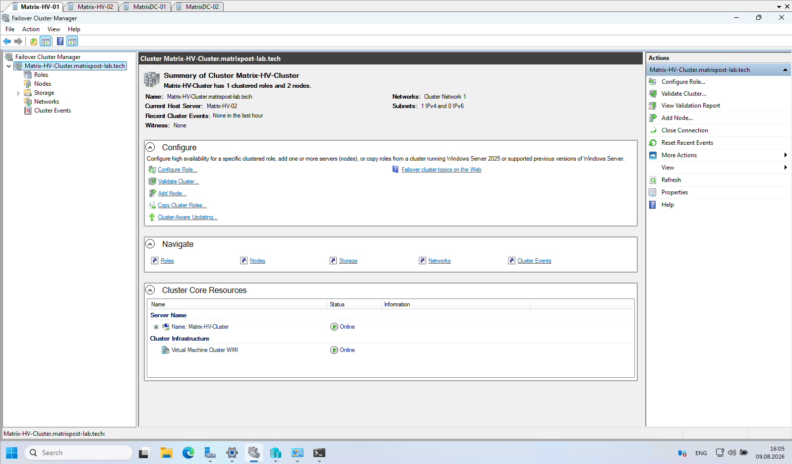
At this point, our two Hyper-V hosts are domain joined and configured with redundant Switch Embedded Teaming (SET) virtual switches for both management and VM traffic.
After validating the configuration, we installed Failover Clustering and created the two-node Matrix-HV-Cluster, providing the foundation for highly available Hyper-V workloads.
In Part 3, we will extend our Hyper-V cluster with shared iSCSI storage, configure a Cluster Shared Volume (CSV), and prepare the environment for Live Migration and highly available virtual machines.
This will complete the transition from our basic two-node cluster to a fully functional highly available Hyper-V environment.
Links
Plan for Hyper-V networking in Windows Server
https://learn.microsoft.com/en-us/windows-server/virtualization/hyper-v/plan/plan-hyper-v-networking-in-windows-serverHyper-V Virtual Switch
https://learn.microsoft.com/en-us/windows-server/virtualization/hyper-v/virtual-switchNetwork recommendations for Hyper-V in a failover cluster
https://learn.microsoft.com/en-us/windows-server/virtualization/hyper-v/failover-cluster-network-recommendationsSwitch Embedded Teaming (SET)
https://learn.microsoft.com/en-us/azure/azure-local/concepts/host-network-requirements/#switch-embedded-teaming-setHyper-V virtualization in Windows Server and Windows
https://learn.microsoft.com/en-us/windows-server/virtualization/hyper-v/overviewHyper-V Architecture
https://learn.microsoft.com/en-us/windows-server/virtualization/hyper-v/architecturePlan for Hyper-V security in Windows Server
https://learn.microsoft.com/en-us/windows-server/virtualization/hyper-v/plan/plan-hyper-v-security-in-windows-serverInstall Hyper-V
https://learn.microsoft.com/en-us/windows-server/virtualization/hyper-v/get-started/install-hyper-vWhat is Nested Virtualization?
https://learn.microsoft.com/en-us/windows-server/virtualization/hyper-v/nested-virtualizationHyper-V Virtual Fibre Channel
https://learn.microsoft.com/en-us/windows-server/virtualization/hyper-v/plan/virtual-fibre-channel-for-hyper-vGuarded fabric and shielded VMs
https://learn.microsoft.com/en-us/windows-server/security/guarded-fabric-shielded-vm/guarded-fabric-and-shielded-vms-top-node