Deploying and Operating Azure Kubernetes Service (AKS) – A Practical Guide – Part 4 – Working with Pods, Deployments, and Services
After deploying and configuring our AKS cluster in the previous parts, we now start working with actual workloads.
In this section, we will deploy our first application, manage it using deployments, and expose it externally using Kubernetes services.
The
kubectl runcommand creates a single, temporary pod that is typically used for testing or troubleshooting and is not managed by Kubernetes beyond its initial creation.In contrast, a Deployment using the command
kubectl create deploymentdefines a desired state for an application and ensures that the specified number of pods is always running, automatically recreating them if they fail.
With the AKS cluster successfully deployed and integrated into our custom network, we can now move on to deploying and managing our first containerized workloads.
In Part 5 coming soon, we will take application exposure to the next level by introducing Ingress, enabling HTTP-based routing, TLS termination, and a centralized entry point for our services.
While a Service of type LoadBalancer exposes a single application on Layer 4 using a dedicated IP address, Ingress operates on Layer 7 and allows multiple services to be exposed through a single entry point, enabling HTTP-based routing and centralized TLS termination.
Stopping an AKS Cluster to Reduce Costs
In lab or development environments, it is often not necessary to run an AKS cluster continuously. To reduce costs, the cluster can be temporarily stopped when not in use.
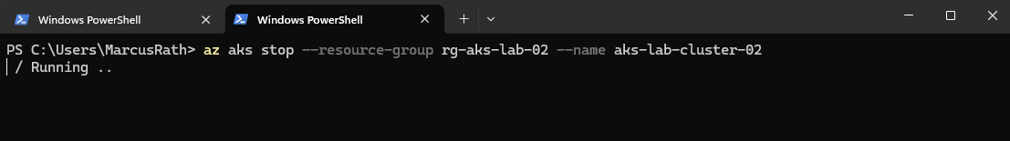
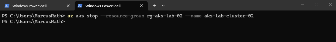
To reduce costs, an AKS cluster can be stopped using az aks stop, which deallocates the worker nodes while preserving the cluster configuration. The cluster can later be started again using az aks start.
PS> az aks stop --resource-group rg-aks-lab-02 --name aks-lab-cluster-02
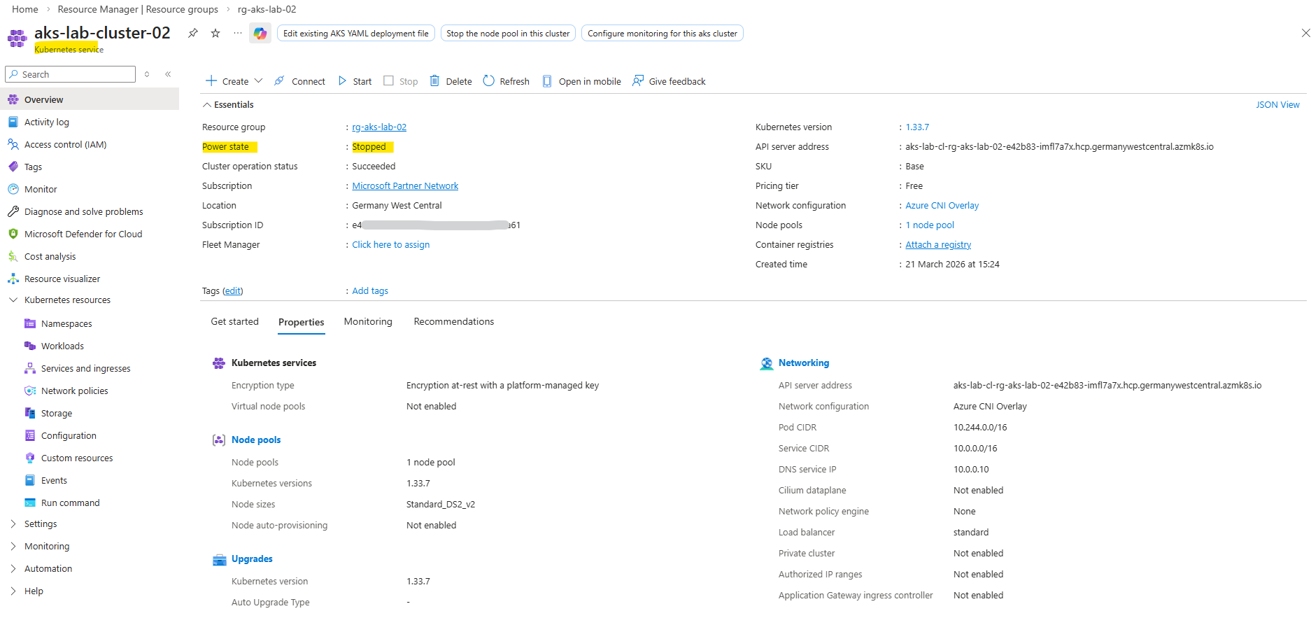
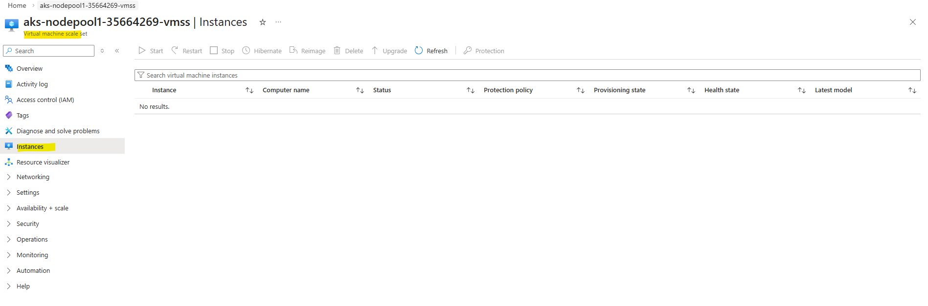
When stopping an AKS cluster, the worker nodes are not merely powered off but fully deallocated, resulting in zero instances in the underlying Virtual Machine Scale Set as shown below. When the cluster is started again, the nodes are recreated dynamically.
This provides a simple way to pause lab environments without deleting and redeploying the cluster.
To start again we can run.
PS> az aks start --resource-group rg-aks-lab-02 --name aks-lab-cluster-02
Cleaning Up the Initial AKS Deployment (from Part 3)
Before continuing with the deployment using a custom virtual network, we first remove the previously created AKS cluster that was deployed with the default AKS-managed networking.
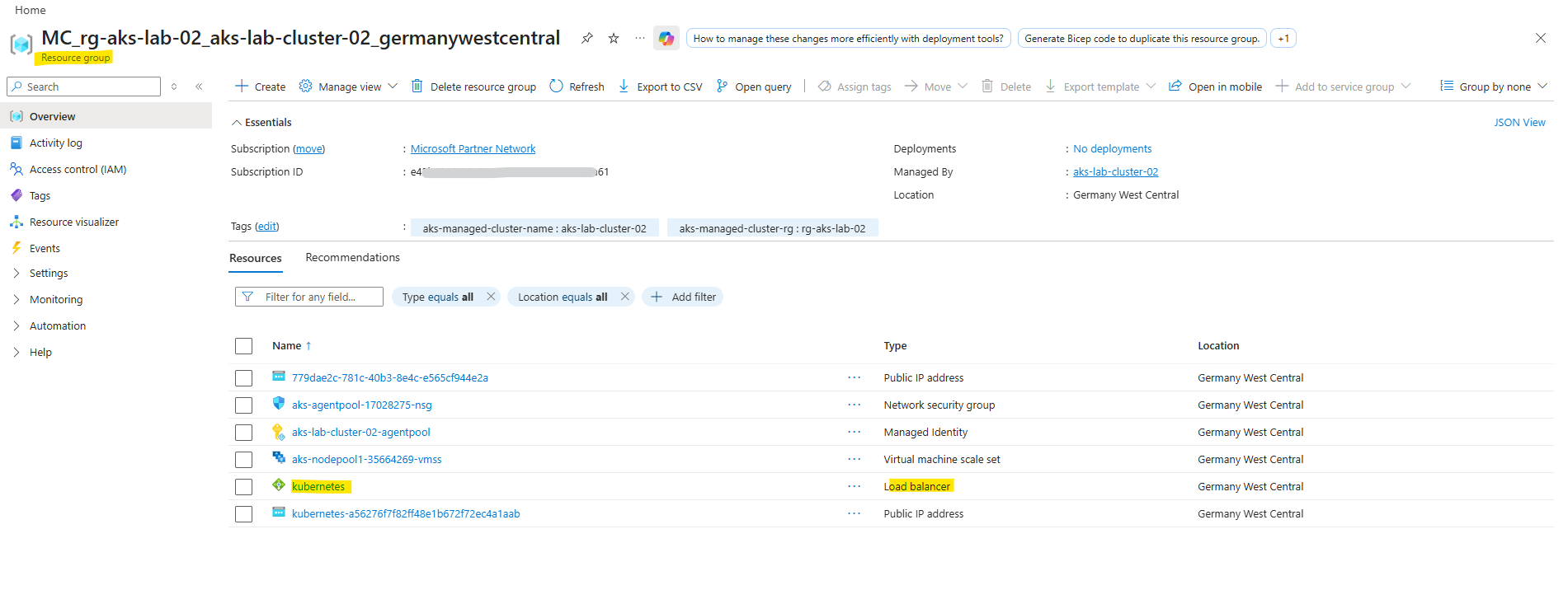
Deleting the AKS cluster automatically removes all associated resources, including the node resource group (MC_*), virtual machine scale sets, networking components, and the automatically created virtual network.
Resources in the MC_ resource group should not be deleted manually, as they are managed by AKS. Always delete the AKS cluster itself to ensure a clean and consistent removal of all related components.
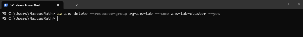
PS> az aks delete --resource-group rg-aks-lab --name aks-lab-cluster --yes
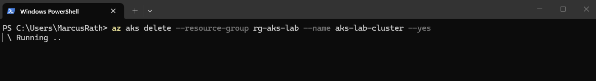
The removing may take several minutes to complete.
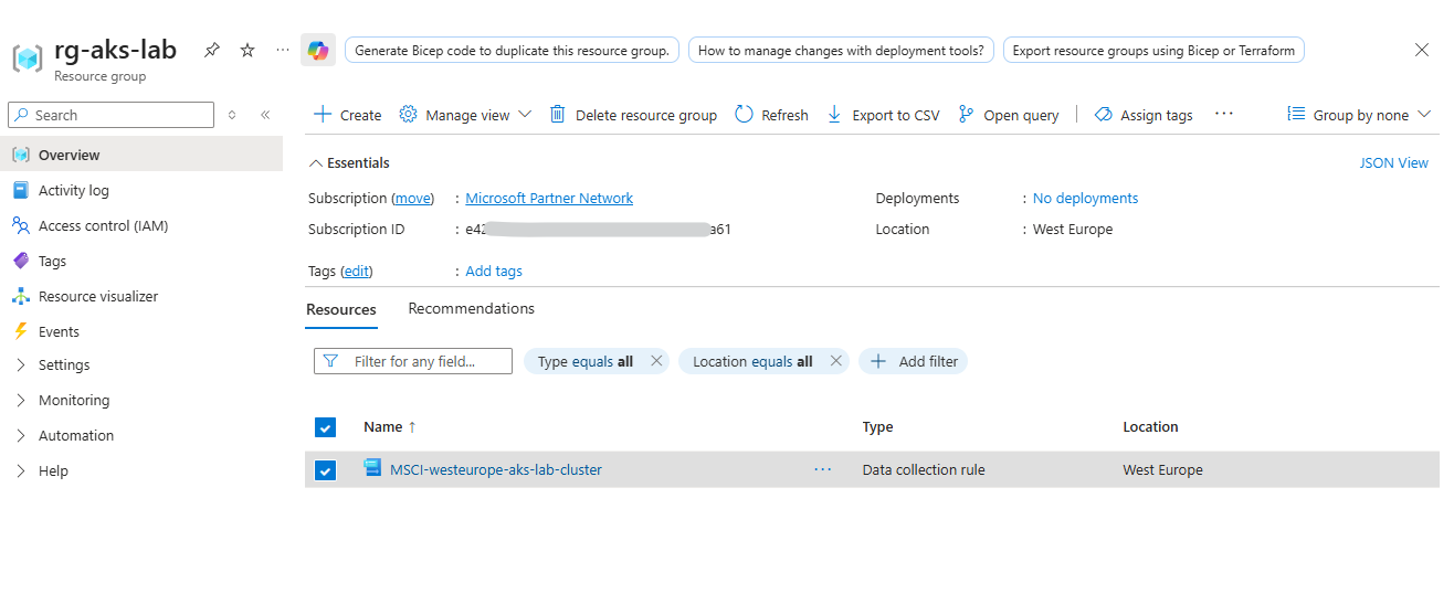
When enabling monitoring, additional Azure Monitor resources such as Data Collection Rules not always removed automatically and may need to be cleaned up manually if no longer required.
The Data Collection Rule was created automatically when enabling monitoring using the
az aks create--enable-addons monitoringcommand, which activates Azure Monitor for the AKS cluster.
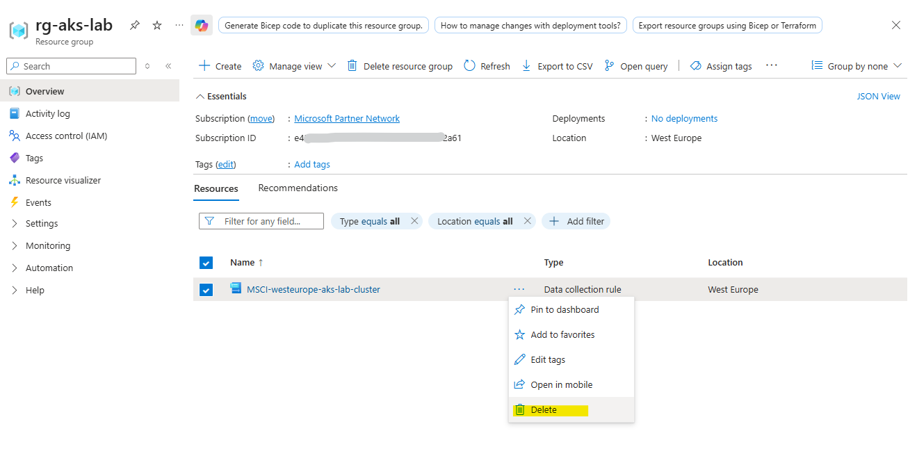
We can delete by using the Azure Portal or the CLI.
PS> az monitor data-collection rule delete --name MSCI-westeurope-aks-lab-cluster --resource-group <resource-group>
Accessing AKS Worker Nodes via Site-to-Site VPN (pfSense Hub)
In AKS, direct access to worker nodes is typically not required for day-to-day operations, as workloads are managed through the Kubernetes API. However, in certain scenarios, such as advanced troubleshooting or network diagnostics, access to the underlying nodes can be useful.
In this setup, the AKS worker nodes are deployed with private IP addresses inside the custom VNet and are not directly accessible from the internet. Instead of using a jump host, access is provided through a site-to-site IPsec VPN established between the hub VNet (pfSense) and the on-premises vSphere network.
This allows direct and secure connectivity from the on-prem environment to the AKS worker nodes over private IP addresses, reflecting a typical hybrid network design used in enterprise environments.
About building a Site-to-Site VPN between Azure and On-Prem by using pfSense on both Sites, you can read my following post. This approach is ideal for labs and cost-conscious setups, since you won’t pay for an always-on Azure VPN tunnel when testing or experimenting.
Or by using the classic Azure VPN Gateway you can read my following post.
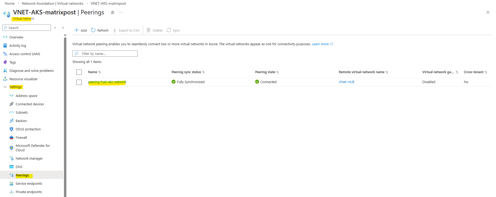
I also have peered my new AKS virtual network with my Hub virtual network to route traffic from Azure to my on-prem network and vice versa by using the established IPSec VPN Tunnel in my Hub virtual network.
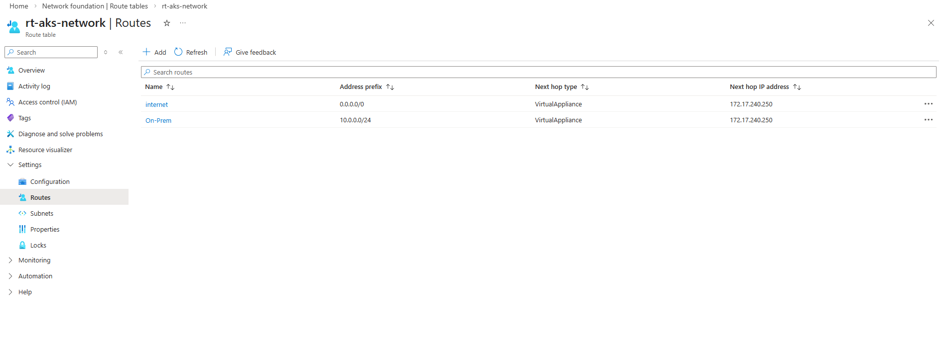
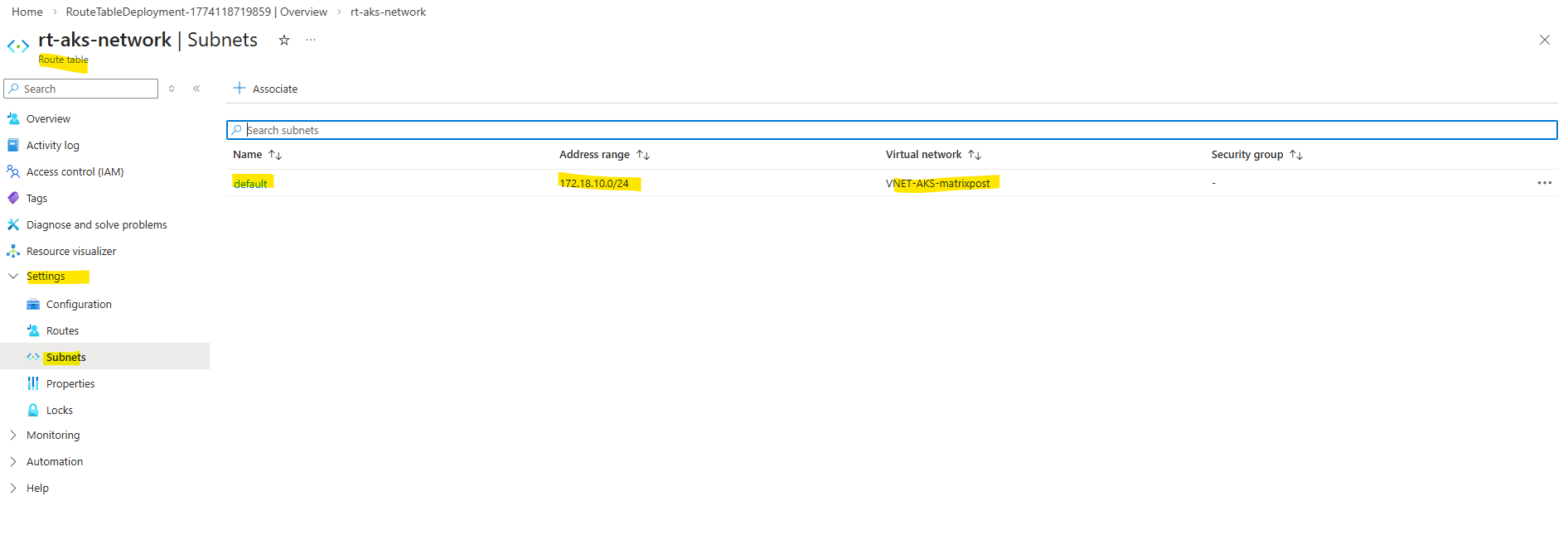
I also created a route table for this new AKS virtual network and subnet to route traffic destined to on-premise through the pfSense appliance running in the Hub network.
The az aks get-credentials command is used to retrieve Kubernetes API access and configure the local kubeconfig file. It is not related to SSH access to the worker nodes, which is configured separately using SSH keys during cluster creation shown in Part 3 running the command below with the flag --generate-ssh-keys.
PS>  az aks create --resource-group rg-aks-lab-02 --name aks-lab-cluster-02 --location germanywestcentral --node-count 2 --network-plugin azure --network-plugin-mode overlay --vnet-subnet-id $AKS_SUBNET_ID --pod-cidr 10.244.0.0/16 --service-cidr 10.245.0.0/16 --dns-service-ip 10.245.0.10 --enable-addons monitoring --generate-ssh-keys

# define node size
# --node-vm-size Standard_DS2_v2

# define AKS tiere
# --tier standard
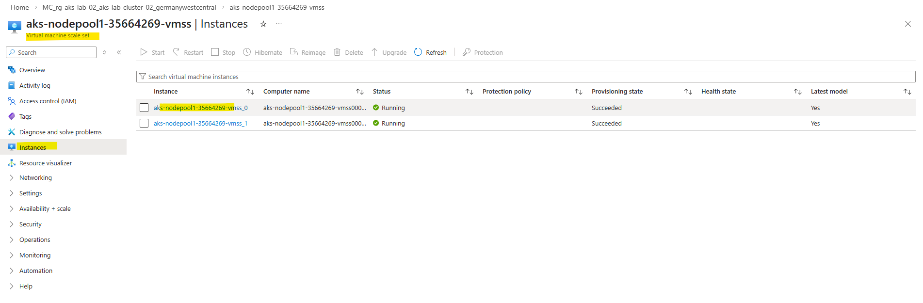
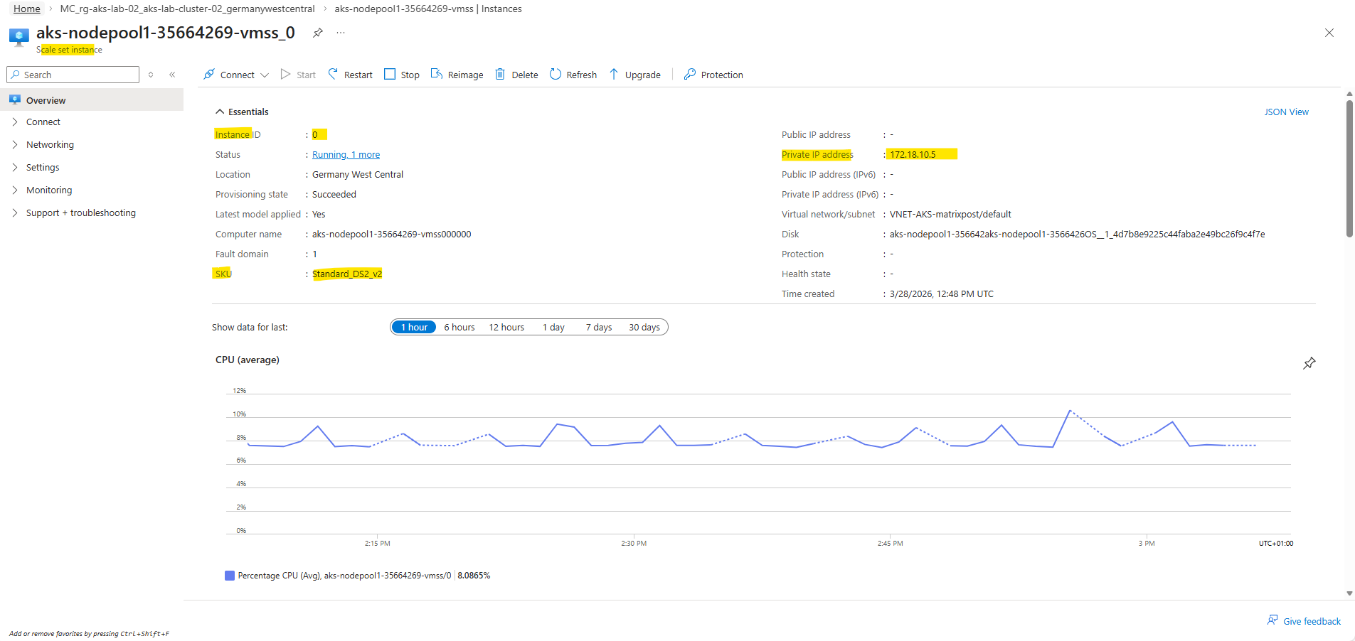
To identify the private IP address of a worker node, navigate to the Azure Virtual Machine Scale Set (VMSS) of the AKS cluster and select one of the instances. The displayed private IP address (in this case from the 172.18.10.0/24 subnet) is reachable in my case from the on-premises network via the site-to-site VPN tunnel.
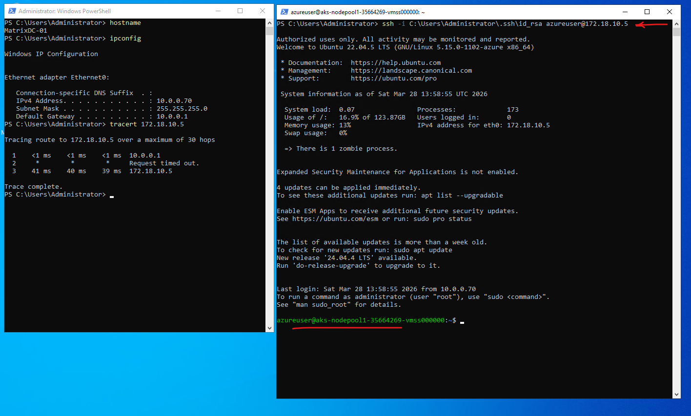
By using the SSH private key generated during cluster creation as mentioned, we can connect directly to the worker node with using the command below. This establishes a secure, key-based connection to the node’s operating system without requiring password authentication.
When using
--generate-ssh-keys, Azure CLI creates the SSH key pair in the default user profile directory, typically under~/.ssh(on Windows:C:\Users\<username>\.ssh). The private key (e.g.,id_rsa) remains on the client, while the corresponding public key is injected into the AKS worker nodes during deployment.
PS> ssh -i C:\Users\Administrator\.ssh\id_rsa azureuser@172.18.10.5
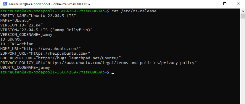
By default, AKS worker nodes are deployed using Ubuntu LTS images. However, alternative operating systems such as Azure Linux (CBL-Mariner) or Windows can also be selected depending on workload requirements.
$cat /etc/os-release
Testing Pod Connectivity with On-Premise Network
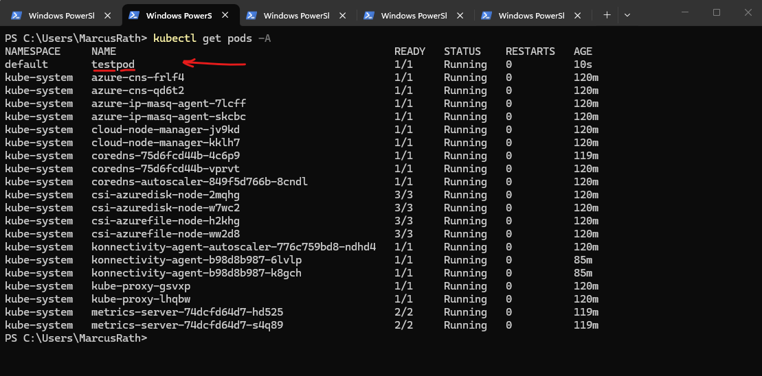
Instead of relying only on Azure-level tools, I use a temporary test pod (BusyBox) to verify connectivity from within the cluster. This allows testing real network paths, such as reaching an on-premises system (10.0.0.70), from the perspective of a running workload.
First we need to retrieve the credentials for our AKS cluster as shown in Part 3.
The BusyBox image is a lightweight container that includes a minimal set of common Linux utilities, making it ideal for quick troubleshooting and testing tasks within a Kubernetes cluster.
# Once the cluster is deployed, we retrieve the credentials to interact with it:
PS> az aks get-credentials --resource-group rg-aks-lab-02 --name aks-lab-cluster-02

PS> kubectl run testpod --image=busybox -it --rm -- sh
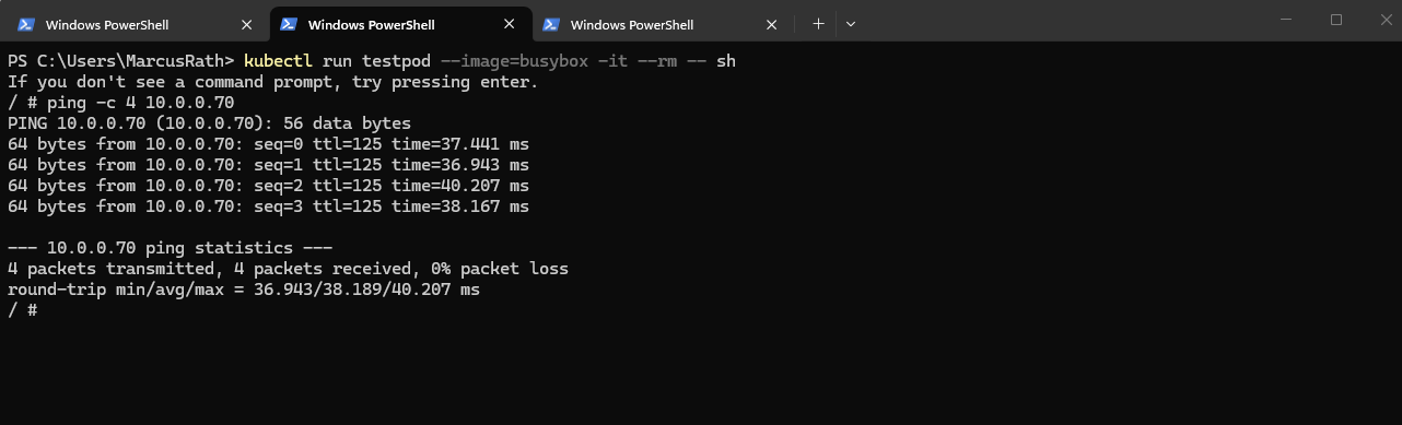
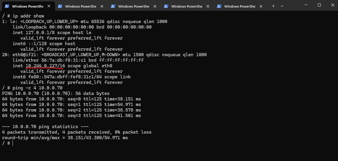
With Azure CNI Overlay, pod-initiated connectivity to my on-prem network should work without advertising the pod CIDR to on-prem, because traffic leaving the cluster is SNATed to the node’s primary IP. Microsoft explicitly states that communication to endpoints outside the cluster, including on-premises networks and peered VNets, uses the nnode IP through NAT, translating the pod’s overlay IP to the VM’s primary IP.
Source: https://learn.microsoft.com/en-us/azure/aks/concepts-network-azure-cni-overlay
/ # ip addr show
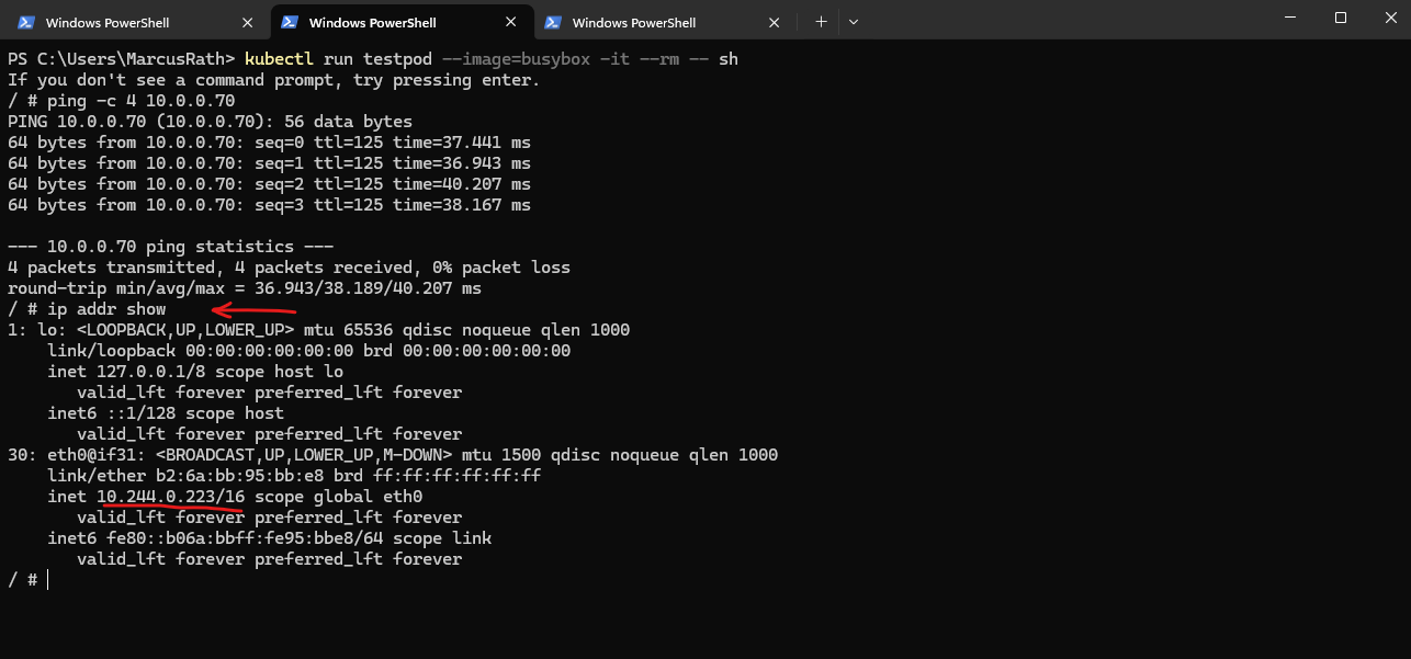
So in my case, the pod IP 10.244.0.223 does not need to be known on-prem. The packet should leave the pod, hit the node, get translated to the node IP 172.18.10.5, and then follow my subnet UDR toward pfSense and the site-to-site VPN.
My traceroute already supports that path, because the first hop is the node 172.18.10.5, which is exactly what we would expect with overlay networking
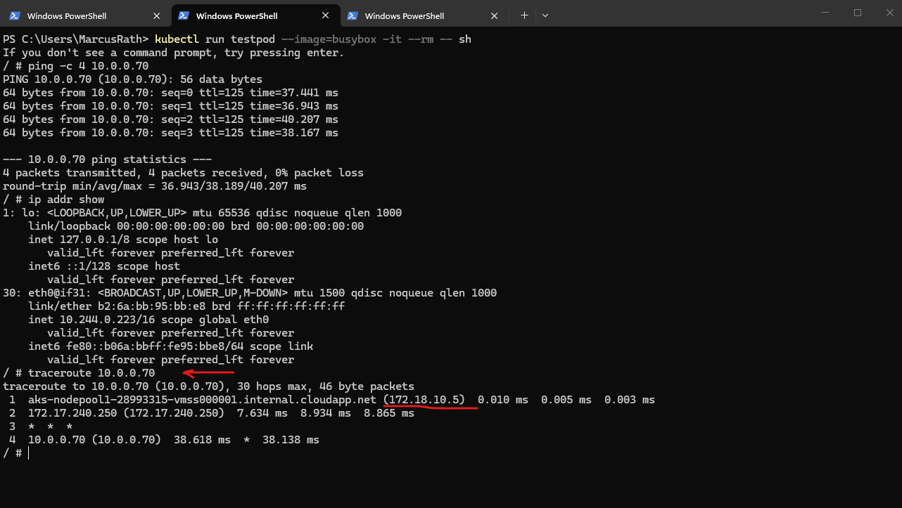
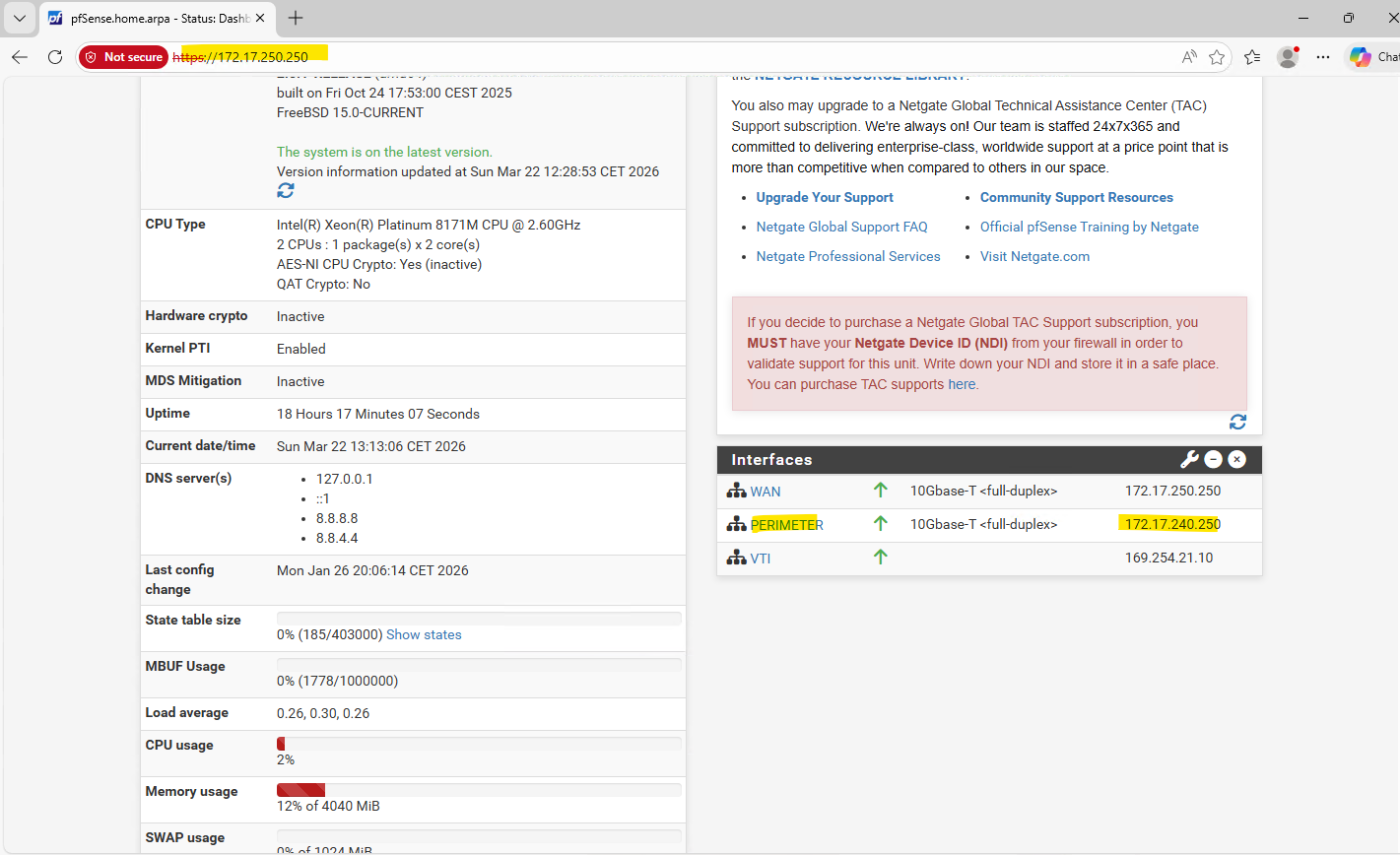
The pfSense appliance running in my Hub virtual network in Azure will use for the internal perimeter network the IP address 172.17.240.250.
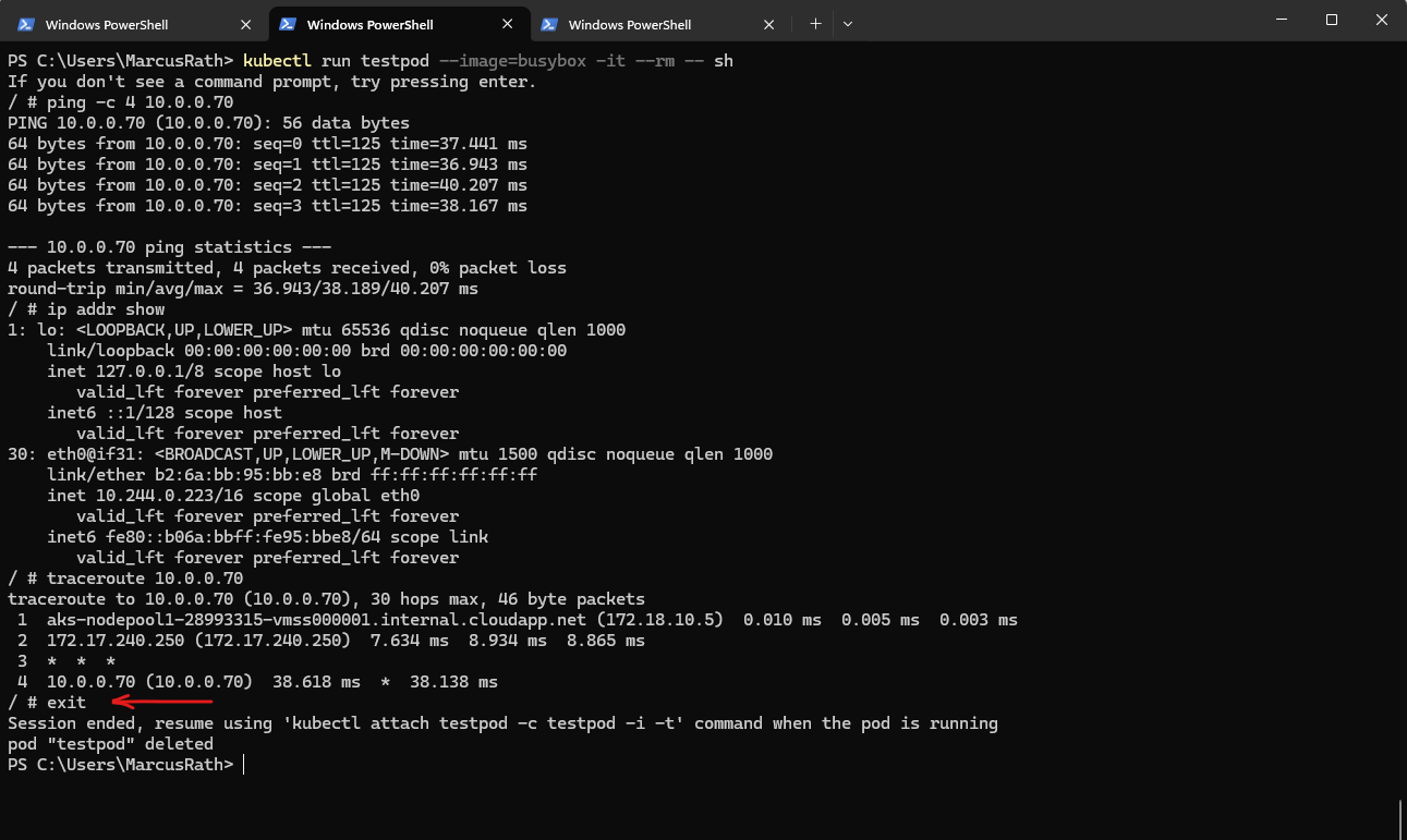
The
--rmflag when running the pod above ensures that the temporary test pod is automatically deleted once the session is closed, keeping the cluster clean.
/ # exit
To verify running workloads, the kubectl get pods -A command can be used to list all pods across all namespaces.
PS> kubectl get pods -A
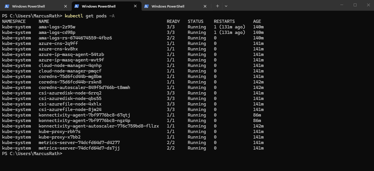
Before exiting the pod, we can verify its presence by listing all running pods, as shown below.
PS> kubectl get pods -A
While connectivity from the pod to the on-premises network works, the reverse direction is not possible because pods in the Azure CNI overlay network use an internal, non-routable CIDR. Outbound traffic is SNATed to the node IP, but inbound traffic from on-premises cannot be routed directly to pod IP addresses.
The IP address of the test pod has changed because the pod was recreated. In Kubernetes, pod IP addresses are dynamically assigned and are not persistent, so a new pod instance always receives a new IP.
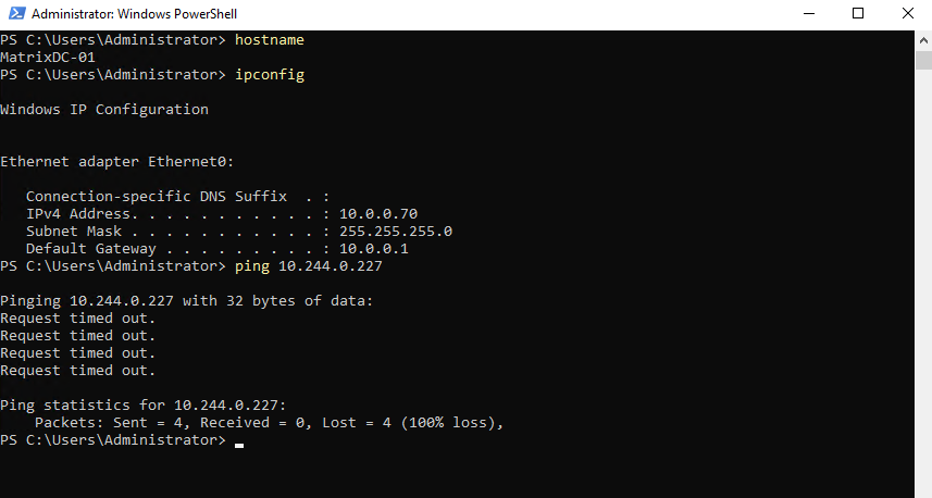
As mentioned from the pod to the on-premises network works because SNAT is used.
Deploying Our First Application
To get started, we deploy a simple application using a Kubernetes deployment, which ensures that our application runs reliably and can be scaled easily.
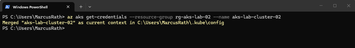
Before deploying our first application, we need to connect to the AKS cluster by retrieving its credentials and configuring the local kubeconfig context.
This command updates the local kubeconfig file and sets the current context, allowing
kubectlto interact with the specified AKS cluster.The
az aks get-credentialscommand configures access to the Kubernetes API using the current Azure login context. This is independent of the SSH keys generated during cluster deployment, which are only used for accessing the underlying virtual machines (worker nodes).
PS> az aks get-credentials --resource-group rg-aks-lab-02 --name aks-lab-cluster-02
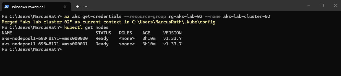
To verify the connection, we can list the cluster nodes:
PS> kubectl get nodes
Even when using --generate-ssh-keys, Azure does not necessarily create a new SSH key pair for every AKS deployment. The parameter ensures SSH key material is available for the node VMs if needed, but it is independent of Kubernetes API access and may reuse existing keys.
After setting up the AKS cluster and verifying connectivity, the next step is to deploy our first containerized application.
For this first containerized application we will use a simple NGINX deployment to demonstrate how workloads are created, managed, and exposed in Kubernetes.
Therefore run:
PS> kubectl create deployment nginx --image=nginx
PS> kubectl get deployments
PS> kubectl get pods -o wide
The output confirms that the NGINX deployment was created successfully and that the pod is already running on one of the AKS worker nodes. With
kubectl get pods -o wide, we can also see the assigned pod IP address and the hosting node, as well as the previously created BusyBox test pod, which was used to validate connectivity with the on-premises network.

First, we connected to the AKS cluster context and then created a simple deployment based on the NGINX container image.
Kubernetes here automatically schedules the pod on one of the worker nodes and ensures that the desired state is maintained.
To make the NGINX application accessible, it must be exposed through a Kubernetes Service, as pod IP addresses are neither stable nor directly reachable from outside the cluster.
A Service provides a consistent endpoint and ensures that incoming traffic is correctly routed to the underlying pods.
Exposing the Application Externally with a Service (Public IP Access)
After successfully deploying the NGINX application, it is not yet accessible from outside the cluster, as pods use ephemeral and non-routable IP addresses.
To make the application reachable, we need to expose it using a Kubernetes Service, which provides a stable endpoint and handles the routing of incoming traffic to the underlying pods.
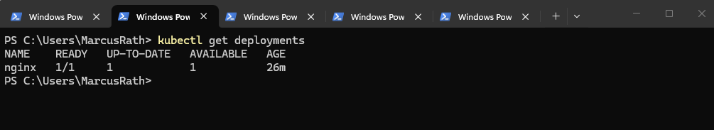
Before exposing the application, we can first list the existing deployments to verify the correct name:
This command shows all deployments in the current namespace, allowing us to confirm that the NGINX deployment named
nginxexists and can be referenced when creating the Service.
PS> kubectl get deployments

# we created the NGINX application using: kubectl create deployment nginx --image=nginx
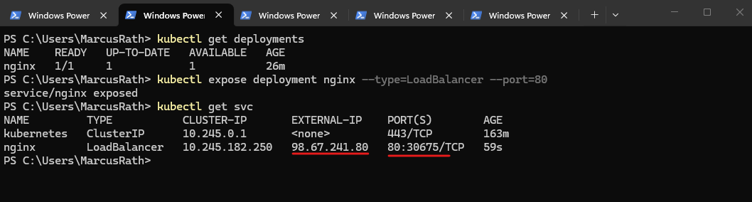
The command below creates a Kubernetes Service that configures the already existing Azure Load Balancer to expose the NGINX Deployment through a public IP address. Incoming traffic on port 80 is forwarded to the cluster nodes and then distributed internally across the available pods.
AKS reuses the managed Azure Load Balancer created during cluster deployment and dynamically adds frontend configurations and rules for each exposed service.
PS> kubectl expose deployment nginx --type=LoadBalancer --port=80

To verify that the Service was created successfully, run:
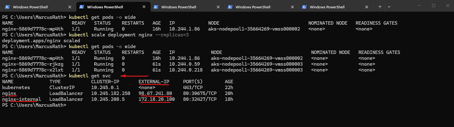
After exposing the deployment, Kubernetes automatically creates a Service of type
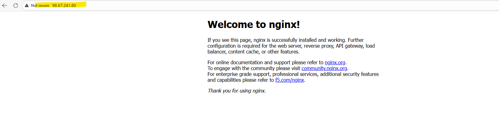
LoadBalancerand assigns both a cluster-internal IP address and an external IP. In this case, the NGINX application is now reachable via the external IP address98.67.241.80on port 80.
PS> kubectl get svc
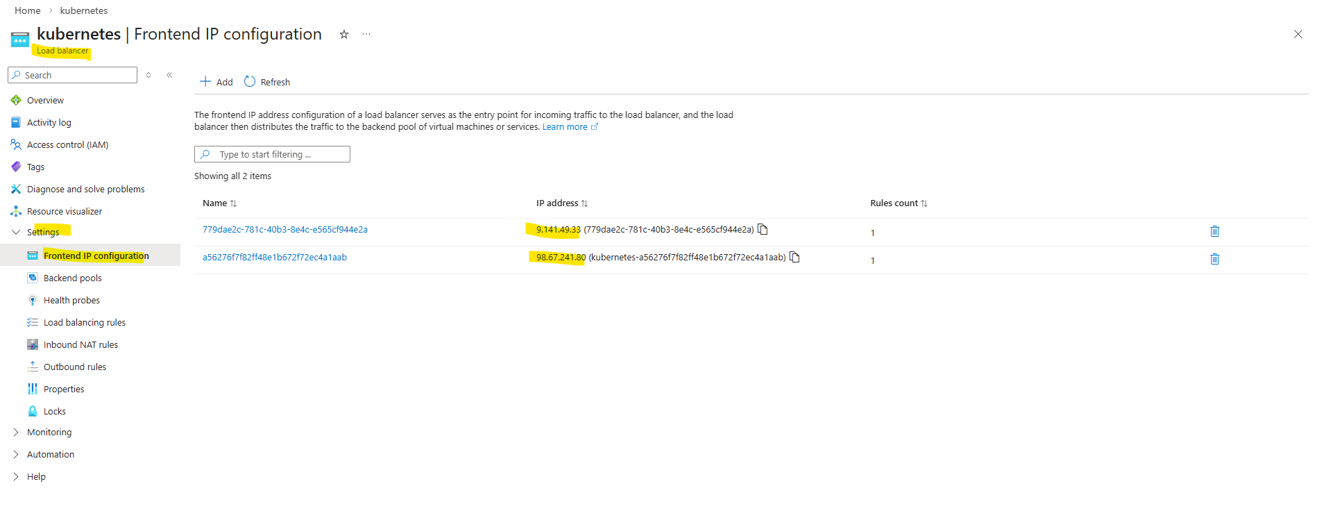
The type of an Azure Load Balancer (public or internal) is determined by its frontend IP configuration. Public frontends use a public IP address, while internal frontends use a private IP address from a virtual network subnet. A single Load Balancer can have both types of frontends configured simultaneously.
We can now verify the deployment by opening a web browser and navigating to the assigned external IP address. The default NGINX welcome page should be displayed, confirming that the application is successfully exposed and reachable as shown below.
In AKS, the managed Azure Load Balancer can have multiple frontend IP configurations serving different purposes. One public IP is typically used for inbound traffic to Kubernetes Services (via load balancing rules), while another public IP is used for outbound connectivity (via outbound rules), enabling the cluster nodes and pods to access the internet.
While it is technically possible to use a single public IP address for both inbound and outbound traffic, AKS separates these functions to avoid SNAT port exhaustion and to improve scalability and reliability. By using a dedicated outbound IP for source NAT, the platform ensures stable inbound connectivity for services while allowing outbound traffic to scale independently.
As mentioned the managed Azure Load Balancer is created during cluster deployment.
Exposing the Application Internally with a Service (Private IP Access)
In addition to exposing applications to the internet, it is often required to make services accessible only within a private network, such as a connected on-premises environment. In this section, we will expose the NGINX application using an internal LoadBalancer, allowing access through a private IP address from the AKS virtual network, which can be reached securely over my site-to-site VPN.
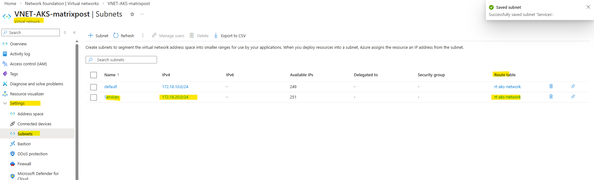
To expose the application internally using a private IP address, I will first create an additional subnet in the AKS virtual network with the address space 172.18.20.0/24. This dedicated subnet will be used to host the frontend IP configuration of the internal Azure Load Balancer.
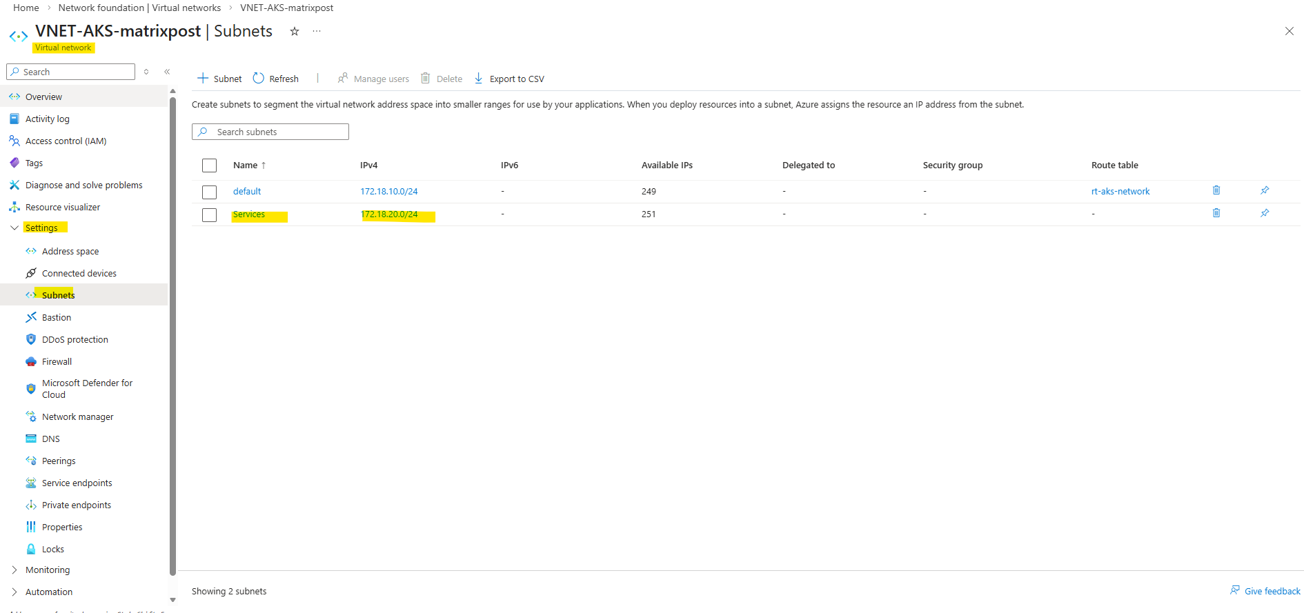
Also associate the route table containing the on-prem network route with the newly created service subnet to ensure seamless connectivity between the AKS services and the on-prem environment.
To provision an internal LoadBalancer, we define a new Kubernetes Service using a YAML manifest with the required Azure-specific annotations. This configuration is then applied to the cluster, which triggers AKS to create an internal Azure Load Balancer with a private IP address in the specified subnet.
This tells AKS to create an internal load balancer, place its frontend into the subnet named Services, and assign the private IP 172.18.20.10.
Every
type=LoadBalancerService
→ creates/uses an Azure Load Balancer
apiVersion: v1
kind: Service
metadata:
name: nginx-internal
annotations:
service.beta.kubernetes.io/azure-load-balancer-internal: "true"
service.beta.kubernetes.io/azure-load-balancer-internal-subnet: "Services"
service.beta.kubernetes.io/azure-load-balancer-ipv4: "172.18.20.100"
spec:
type: LoadBalancer
selector:
app: nginx
ports:
- port: 80
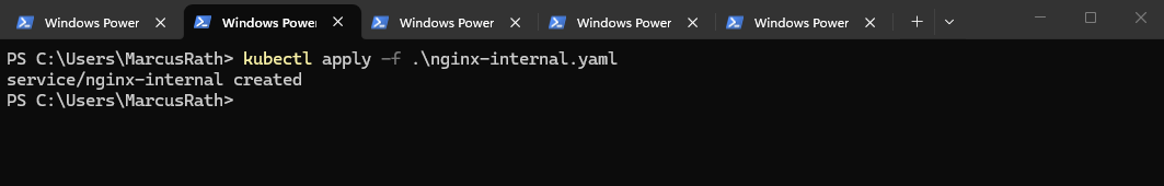
targetPort: 80Save it as nginx-internal.yaml, then run:
PS> kubectl apply -f .\nginx-internal.yaml
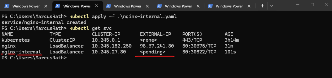
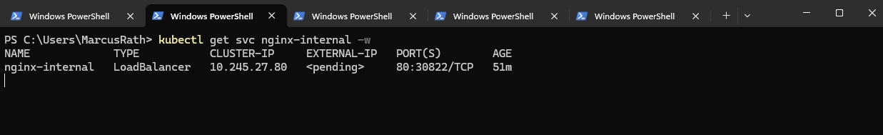
Verify the newly created Service.
<pending>means AKS hasn’t finished provisioning the Azure internal load balancer frontend yet. For an internalLoadBalancerservice on a different subnet, the two most common causes are: the subnet name/IP annotation is wrong, or the AKS cluster identity lacks permission to use that subnet. AKS supports placing the internal LB on a different subnet in the same VNet, but the cluster identity needs access there.
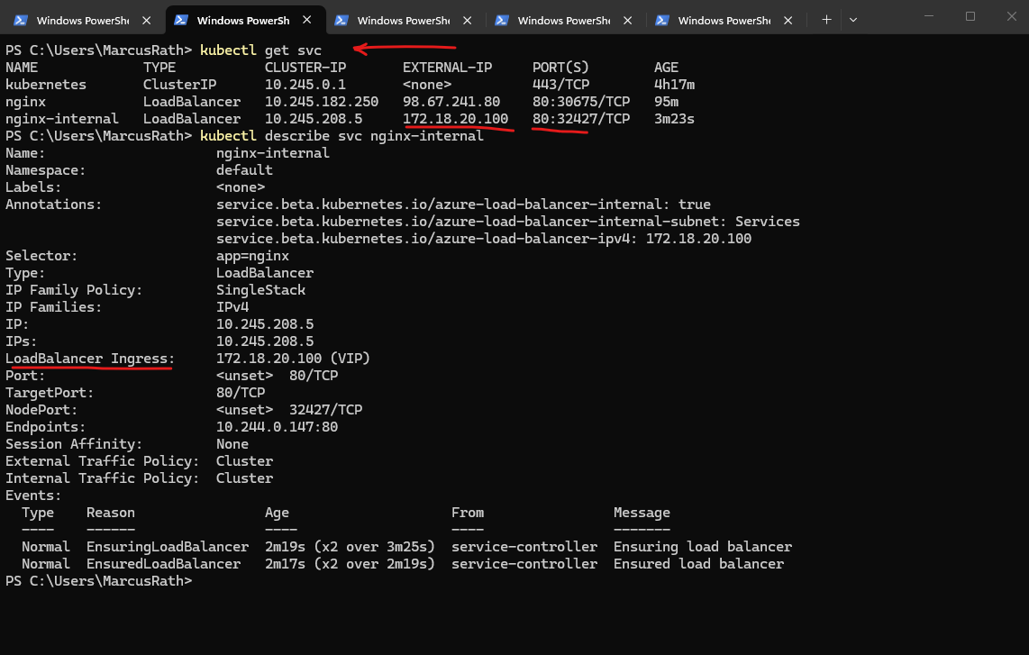
PS> kubectl get svc
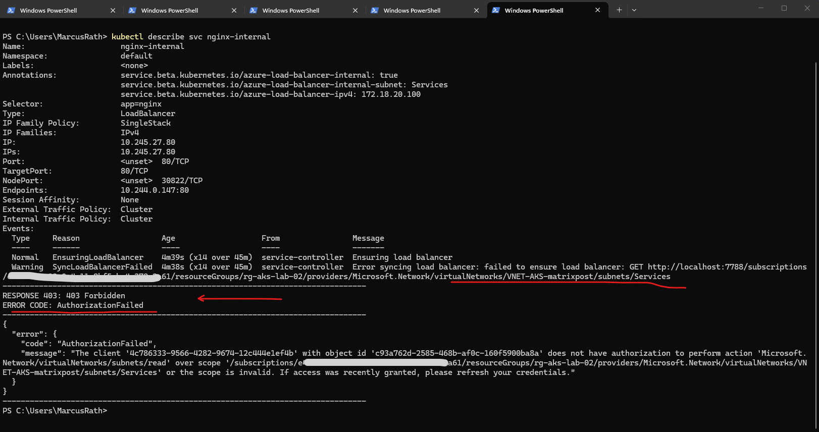
To troubleshoot the deployment and verify whether the service was created successfully, we can use the command below. This provides detailed information about the service, including events and error messages if the provisioning of the internal load balancer fails.
In my case the AKS cluster identity does not have permission to read the Services subnet, so AKS cannot place the internal load balancer frontend there. For an internal LB on a different existing subnet, AKS needs permission to manage network resources, and specifically Read access to that subnet.
PS> kubectl describe svc nginx-internal
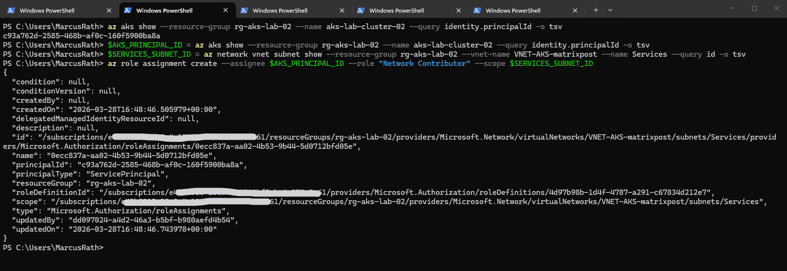
First, get the AKS cluster identity principal ID. Then assign at least Network Contributor on the new subnet. Subnet scope is the cleanest:
PS> az aks show --resource-group rg-aks-lab-02 --name aks-lab-cluster-02 --query identity.principalId -o tsv
PS> $AKS_PRINCIPAL_ID = az aks show --resource-group rg-aks-lab-02 --name aks-lab-cluster-02 --query identity.principalId -o tsv
PS> $SERVICES_SUBNET_ID = az network vnet subnet show --resource-group rg-aks-lab-02 --vnet-name VNET-AKS-matrixpost --name Services --query id -o tsv
PS> az role assignment create --assignee $AKS_PRINCIPAL_ID --role "Network Contributor" --scope $SERVICES_SUBNET_ID
After that, wait a minute or two for RBAC propagation, then either recreate the service or just let it reconcile and watch it:
PS> kubectl get svc nginx-internal -w
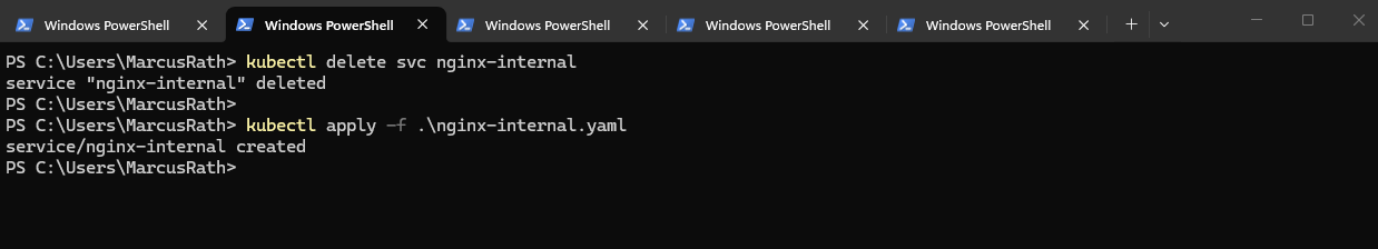
If it stays stuck, delete and recreate it:
PS> kubectl delete svc nginx-internal
PS> kubectl apply -f .\nginx-internal.yaml
Unfortunately still in pending state. Checking again:
PS> kubectl describe svc nginx-internal
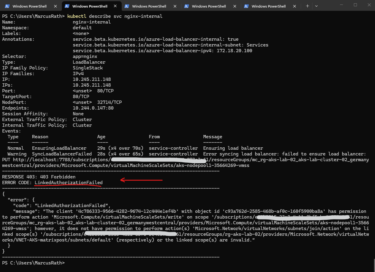
After granting access to the Services subnet, AKS still required subnet join permissions on the default node subnet. Once the AKS managed identity had the necessary rights on both subnets, the internal load balancer could be provisioned successfully.
The AKS identity needs permissions on both:
VNET-AKS-matrixpost/subnets/ServicesVNET-AKS-matrixpost/subnets/default
PS> $AKS_PRINCIPAL_ID = az aks show --resource-group rg-aks-lab-02 --name aks-lab-cluster-02 --query identity.principalId -o tsv
PS> $DEFAULT_SUBNET_ID = az network vnet subnet show --resource-group rg-aks-lab-02 --vnet-name VNET-AKS-matrixpost --name default --query id -o tsv
PS> $SERVICES_SUBNET_ID = az network vnet subnet show --resource-group rg-aks-lab-02 --vnet-name VNET-AKS-matrixpost --name Services --query id -o tsv

PS> az role assignment create --assignee $AKS_PRINCIPAL_ID --role "Network Contributor" --scope $DEFAULT_SUBNET_ID
PS> az role assignment create --assignee $AKS_PRINCIPAL_ID --role "Network Contributor" --scope $SERVICES_SUBNET_ID
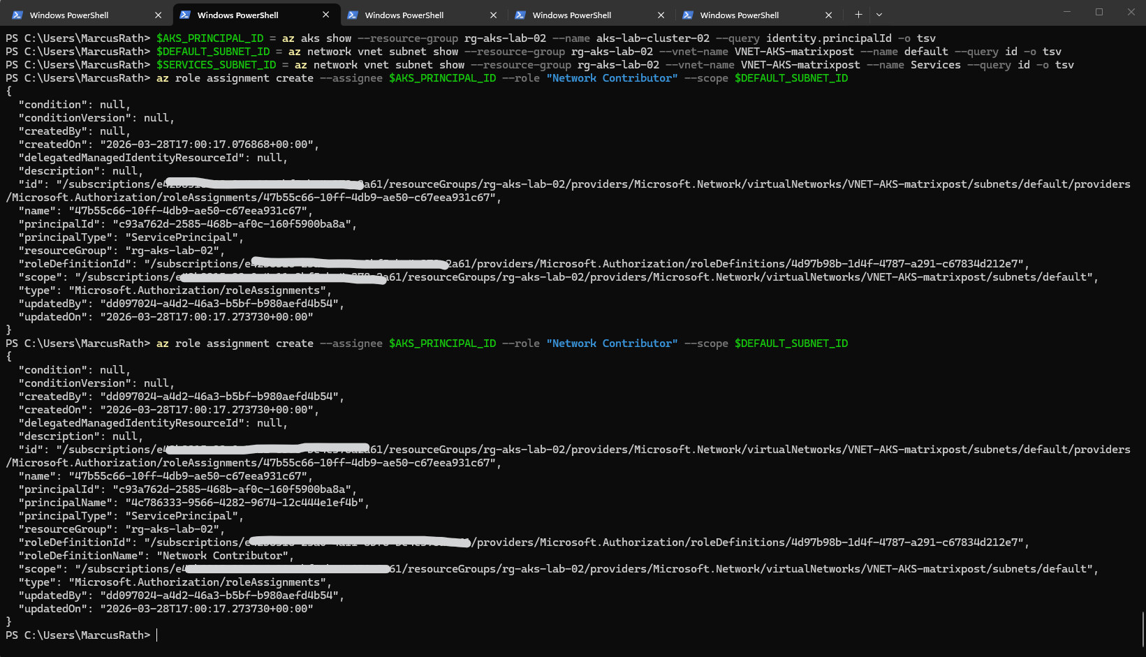
After granting the required permissions to the AKS managed identity, the internal load balancer was provisioned successfully and assigned the private IP 172.18.20.100 from the dedicated Services subnet. This allows the NGINX application to be accessed privately from connected networks without exposing it publicly.
After assigning the required permissions to the AKS managed identity, I deleted the previously created Service and recreated it to trigger a fresh provisioning of the internal load balancer. This ensured that the updated permissions were properly applied during deployment.
PS> kubectl delete svc nginx-internal
PS> kubectl apply -f .\nginx-internal.yaml


PS> kubectl get svc
PS> kubectl describe svc nginx-internal
The application is now reachable from the on-premises network by browsing to http://172.18.20.100, confirming that the internal load balancer is correctly integrated with the site-to-site VPN.
This demonstrates that services exposed via a private IP in the AKS VNet can be accessed seamlessly from connected networks.
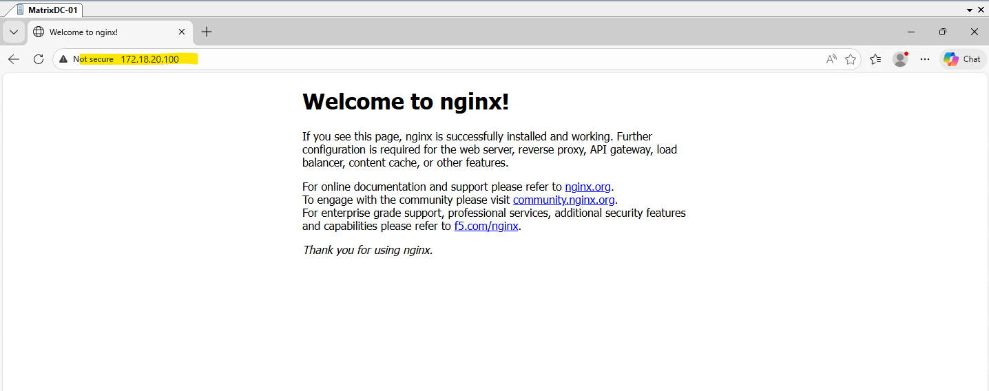
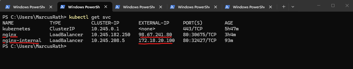
From this point on, the NGINX application can be accessed through both the internal private IP (172.18.20.100) and the external public IP (98.67.241.80).
This allows flexible access depending on the use case, either privately over the VPN or publicly over the internet. Such a setup is common in hybrid environments where the same application needs to be available for both internal and external consumers.
Understanding Deployments, ReplicaSets, and Pods – How Kubernetes Ensures Application Availability
In this section, we take a step back to understand how Kubernetes actually keeps our applications running reliably. While working with Pods, Deployments, and Services, it is important to understand how these components interact behind the scenes.
A Pod is the smallest deployable unit in Kubernetes and represents a running instance of a container. However, Pods are ephemeral by design, if a Pod crashes or is deleted, it is not automatically recreated unless it is managed by a higher-level object.
This is where Deployments come into play. A Deployment defines the desired state of an application, such as the container image to use and the number of replicas that should be running. Kubernetes continuously ensures that this desired state is maintained.
Behind every Deployment, Kubernetes automatically creates and manages a ReplicaSet. The ReplicaSet is responsible for ensuring that the defined number of Pod replicas is always running. If a Pod fails, the ReplicaSet immediately creates a new one to replace it.
When scaling a Deployment, for example by increasing the number of replicas, the ReplicaSet ensures that additional Pods are created. These Pods are identical in terms of configuration but operate independently from each other.
It is important to note that Kubernetes provides replication, not synchronization. Each Pod runs its own instance of the application, and there is no automatic sharing of state or data between them. This design enables high availability and horizontal scalability but requires additional mechanisms for stateful workloads, such as shared storage or application-level clustering.
To distribute traffic across multiple Pods, Kubernetes uses a Service. The Service acts as a stable endpoint and load balances incoming requests across all available Pods, ensuring that the application remains accessible even if individual Pods fail.
In summary, Deployments define what should run, ReplicaSets ensure how many instances are running, and Pods represent where the application actually runs. Together, these components form the foundation for running scalable and resilient applications in Kubernetes.
Scaling a Deployment – From One to Multiple Pods
By default, a Deployment creates a single Pod. This can be verified by listing the currently running Pods:
ps> kubectl get pods -o wide
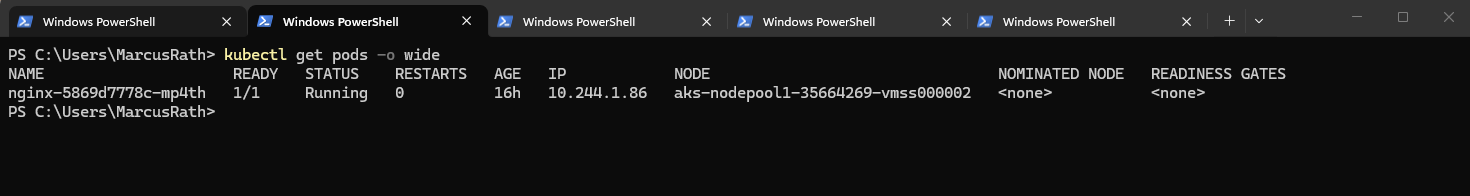
As shown above, only one Pod is running for the NGINX Deployment.
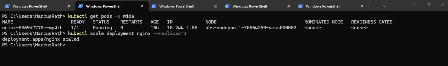
To scale the Deployment and run multiple instances of the application, we can increase the number of replicas:
PS> kubectl scale deployment nginx --replicas=3
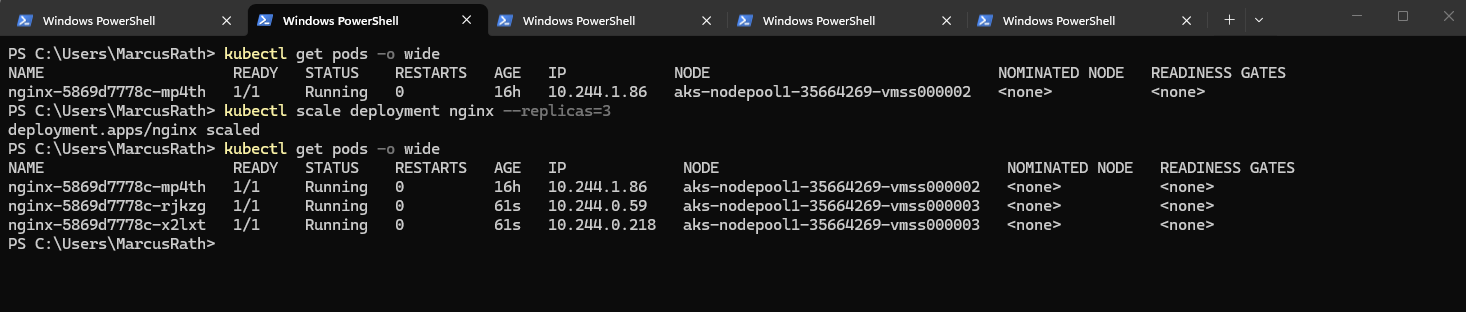
After a few seconds, Kubernetes creates additional Pods:
Instead of scaling a Deployment after creation, you can define the desired number of replicas directly when creating it.
By specifying the number of replicas during creation, Kubernetes immediately deploys multiple identical Pods and ensures that this desired state is maintained from the very beginning.
PS> kubectl create deployment nginx --image=nginx --replicas=3
After scaling the Deployment, both the external and internal LoadBalancer Services we created and shown below automatically distribute incoming traffic across all available pods. The Azure Load Balancer forwards traffic to the cluster nodes, while Kubernetes internally balances the requests across the pods using the Service abstraction.
Scaling a Deployment allows you to run multiple identical instances of an application. Kubernetes automatically creates and maintains the desired number of Pods, enabling high availability and load distribution.
In Part 5 coming soon, we will take application exposure to the next level by introducing Ingress, enabling HTTP-based routing, TLS termination, and a centralized entry point for our services.
Links
Baseline architecture for an Azure Kubernetes Service (AKS) cluster
https://learn.microsoft.com/en-us/azure/architecture/reference-architectures/containers/aks/baseline-aksOverview of Azure CNI Overlay networking in Azure Kubernetes Service (AKS)
https://learn.microsoft.com/en-us/azure/aks/concepts-network-azure-cni-overlay