Deploying NetApp Cloud Volumes ONTAP (CVO) in Azure using NetApp Console (formerly BlueXP) – Part 3 – Configuring Data Services
In this part of the series, we move on to configuring the actual data services on the Cloud Volumes ONTAP system. By default, Cloud Volumes ONTAP deploys a preconfigured data SVM that serves as the foundation for CIFS, NFS, and other data protocols.
This includes creating Storage Virtual Machines (SVMs), provisioning volumes, and enabling access via NFS and CIFS/SMB.
In addition, this part also covers how the Azure networking side fits into the picture, including VNet peering with an existing hub network (which is connected to my on-prem lab), as well as the Internal Load Balancer (ILB) setup.
Since the NetApp Console (BlueXP) does not automatically configure Azure networking for newly created LIFs (Logical Interface), we’ll also look at what needs to be done manually.
For each newly created LIF (Logical Interface), this includes adding the required frontend IP configuration, health probe, and load-balancing rule in Azure.
By the end of this part, the system will be fully prepared to serve storage to workloads in Azure or on-prem when connected through VPN like shown in this part.
In Part 4 of the series, we shift the focus to security and take a closer look at how antivirus protection is implemented in Cloud Volumes ONTAP using ONTAP VSCAN.
In Part 5 we will configure snapshot and backup policies, validate protection workflows, and perform real restore operations to ensure data can be recovered quickly and reliably.
In Part 6 we walk through the process of performing a Non-Disruptive Upgrade (NDU) of a NetApp Cloud Volumes ONTAP (CVO) HA pair in Microsoft Azure.
In Part 7 we dive into NetApp AutoSupport, the critical telemetry system that acts as the heartbeat of our CVO instance.
In Part 8 we focus on Disaster Recovery and explore how to protect Cloud Volumes ONTAP in Azure against outages and unexpected failures.
- First Steps after Deploying Cloud Volumes ONTAP
- Verify System Status and Health
- Understanding the Aggregate Layout
- Create a Storage Virtual Machine (SVM)
- Create a Volume
- ONTAP Volume Management: Automating Growth and Shrinkage (Autosize)
- Snapshot Reserve: How Much Space Do Snapshots Really Need?
- Publishing CIFS/SMB shares
- Configure NFS Export on ONTAP
- Creating Qtrees
- VNet Peering and Site-to-Site VPN Connectivity to the On-Prem Network
- Behind the Scenes of ONTAP HA: How SVMs and LIFs Survive a Node Failure
- Troubleshooting
- Links
First Steps after Deploying Cloud Volumes ONTAP
Once the Cloud Volumes ONTAP HA system is successfully deployed, the environment is technically ready but does not yet provide any usable storage.
Before workloads can access the system, several foundational configuration steps need to be completed.
These steps focus on preparing the storage layer, network access, and data services such as NFS or SMB.
Verify System Status and Health
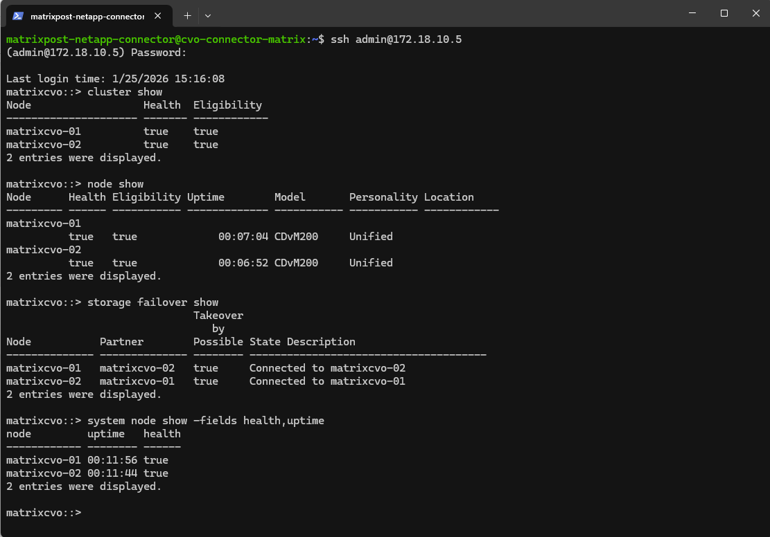
After the Cloud Volumes ONTAP system has started, the first step is to verify that the cluster is healthy and fully operational.
This can be done from the ONTAP CLI, the NetApp Console or directly in ONTAP System Manager, where both nodes should report a healthy state and the HA relationship should be active.
It’s important to ensure that no warnings are present and that all cluster services are running before proceeding with volume creation or data services configuration.
matrixcvo::> cluster show
matrixcvo::> node show
matrixcvo::> storage failover show
matrixcvo::> system node show -fields health,uptime
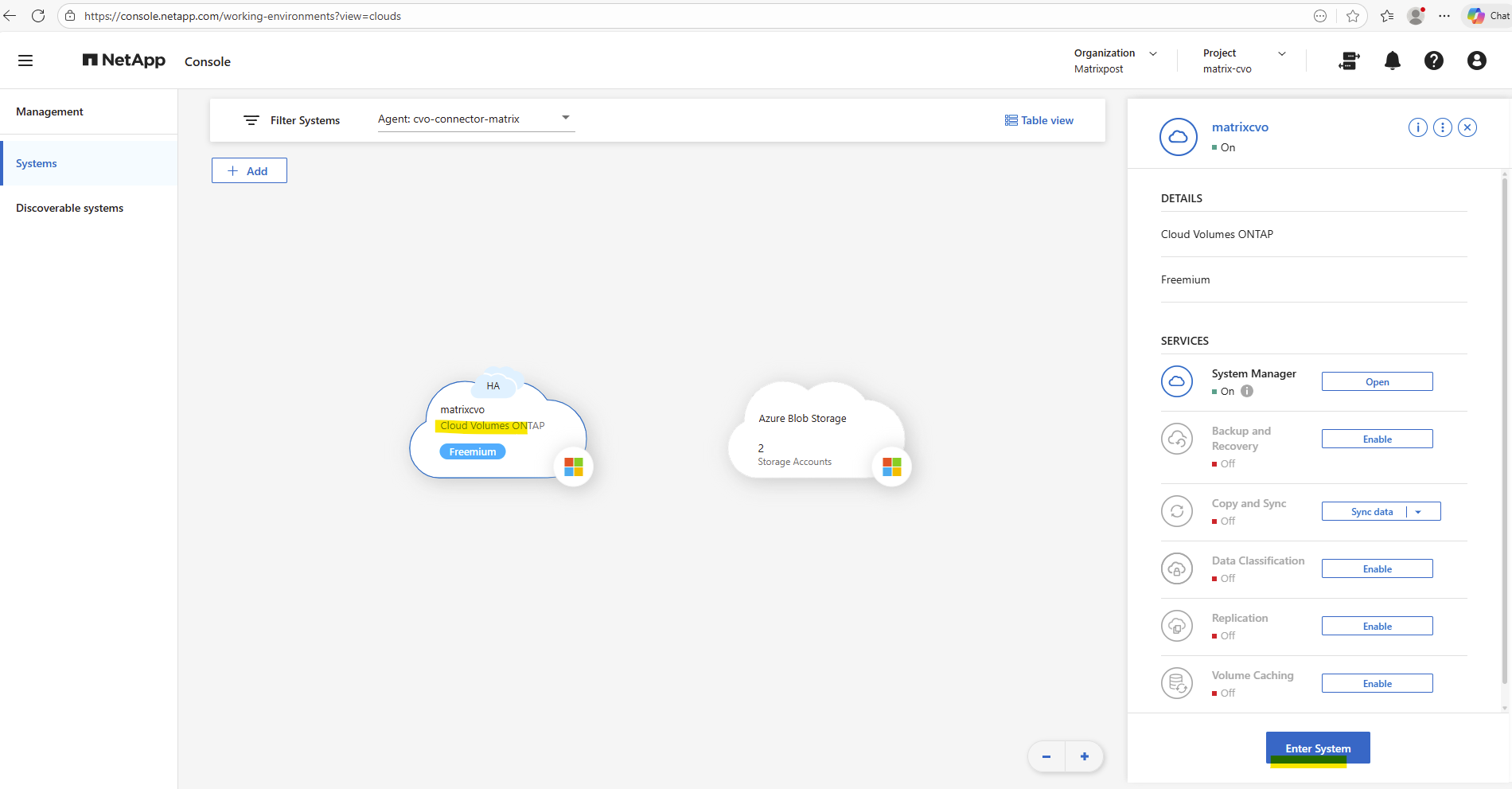
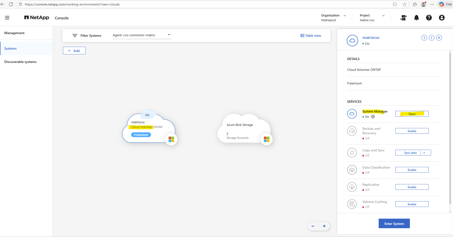
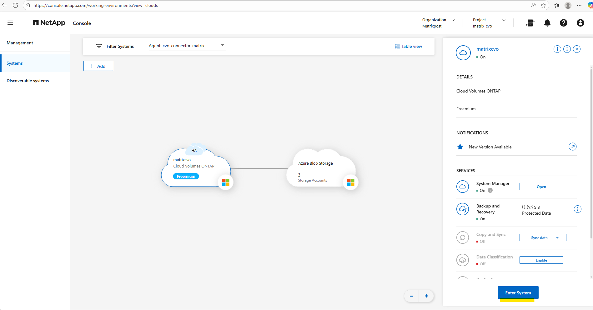
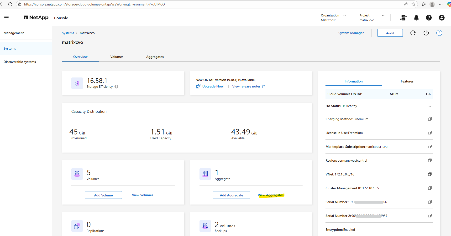
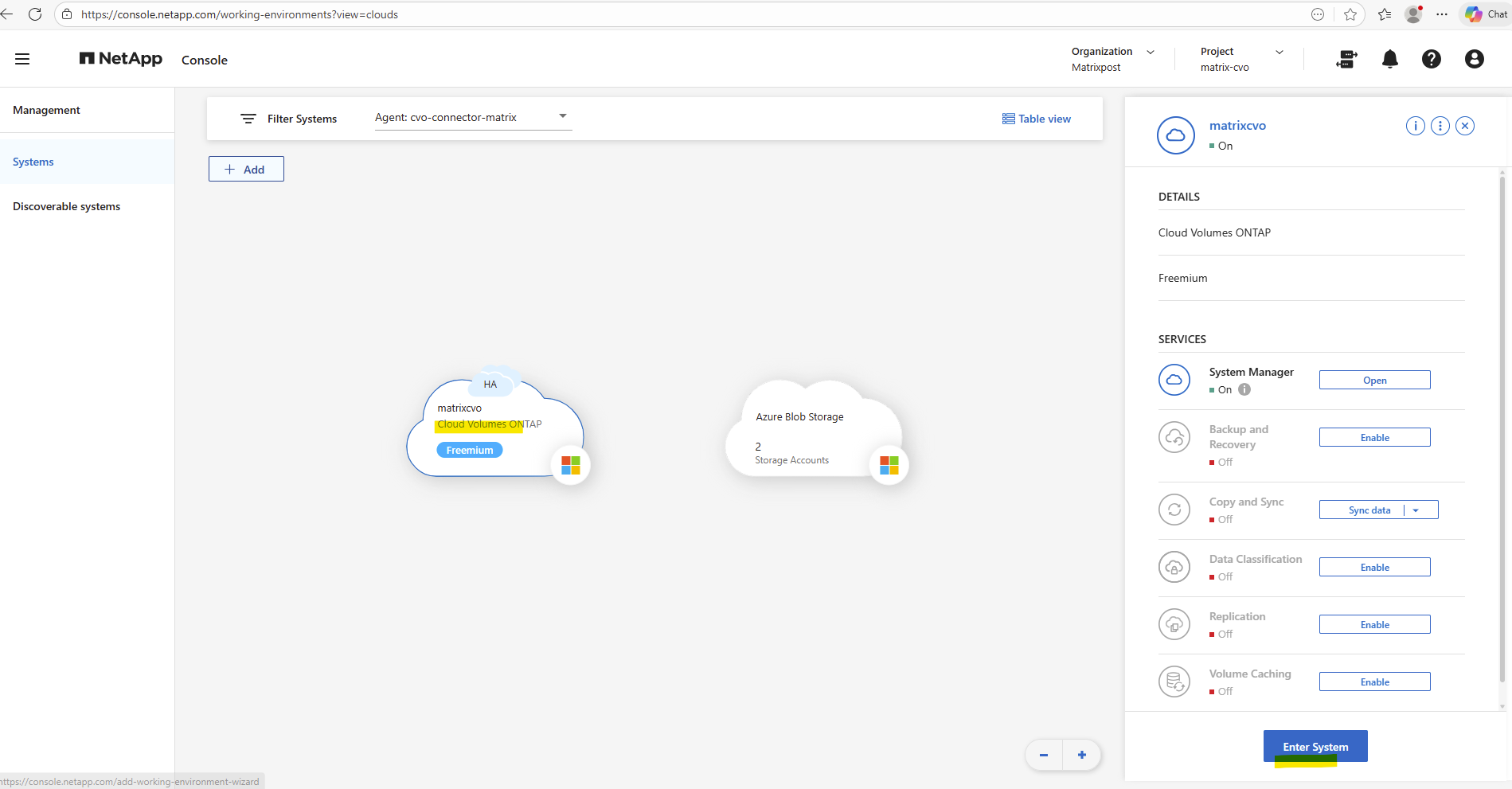
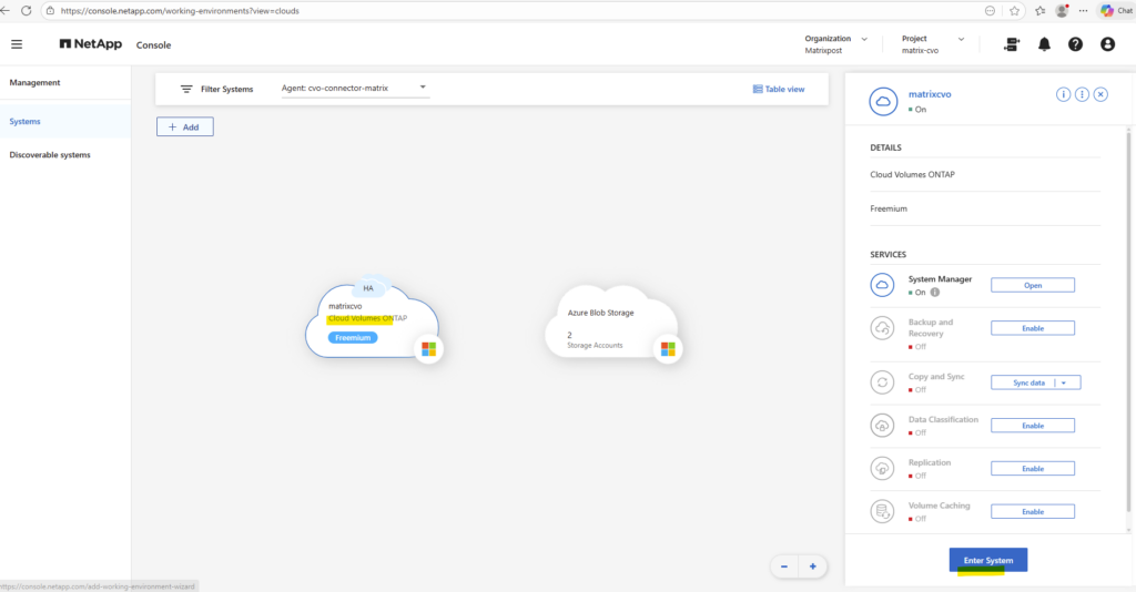
By using the NetApp console we can navigate to Management -> Systems, select the highlighted Cloud Volume ONTAP system and click on Enter System as shown below.
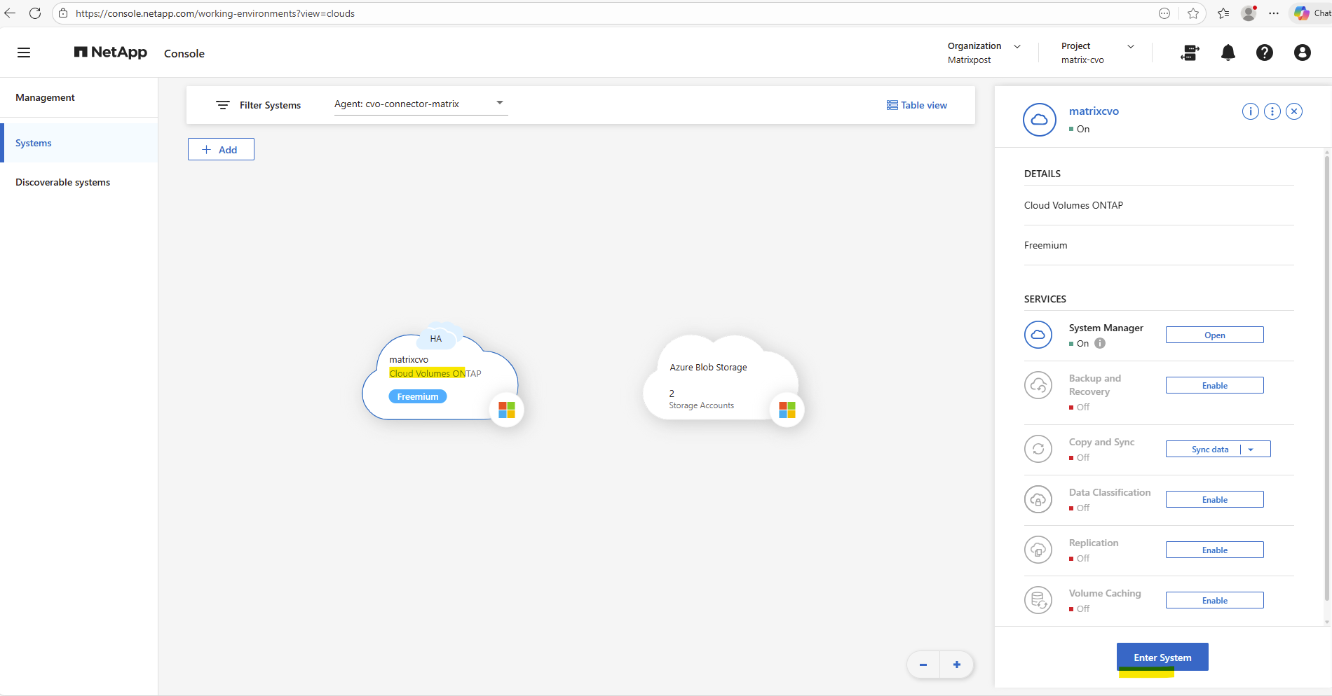
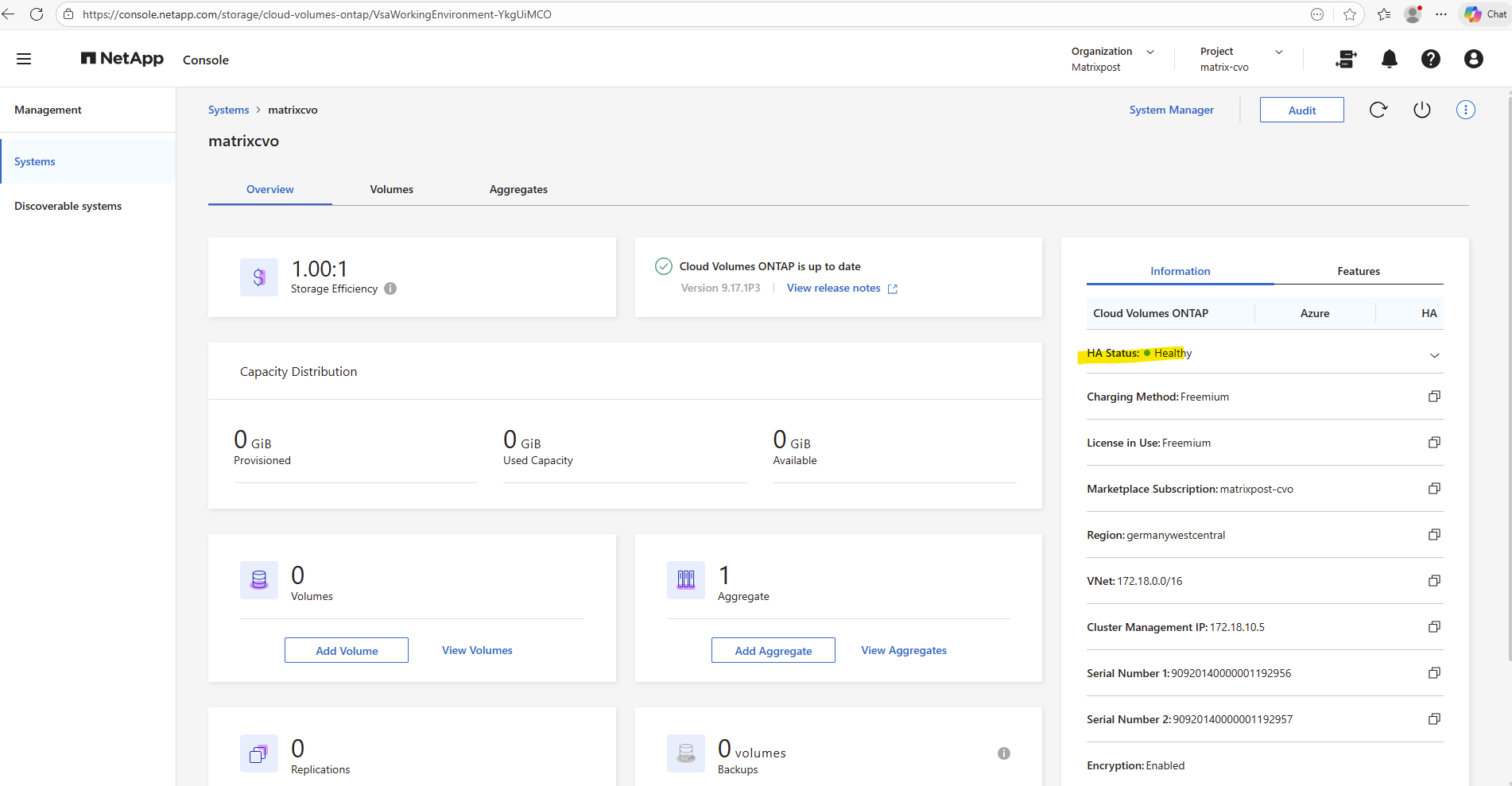
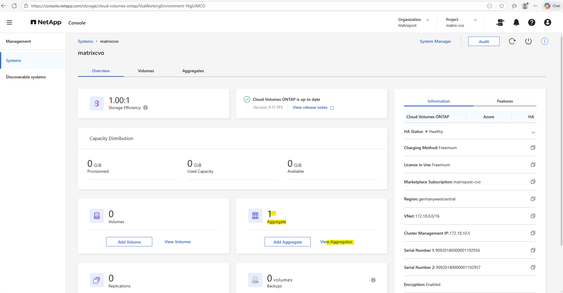
Within the Information tab we will see the HA status health as shown below.
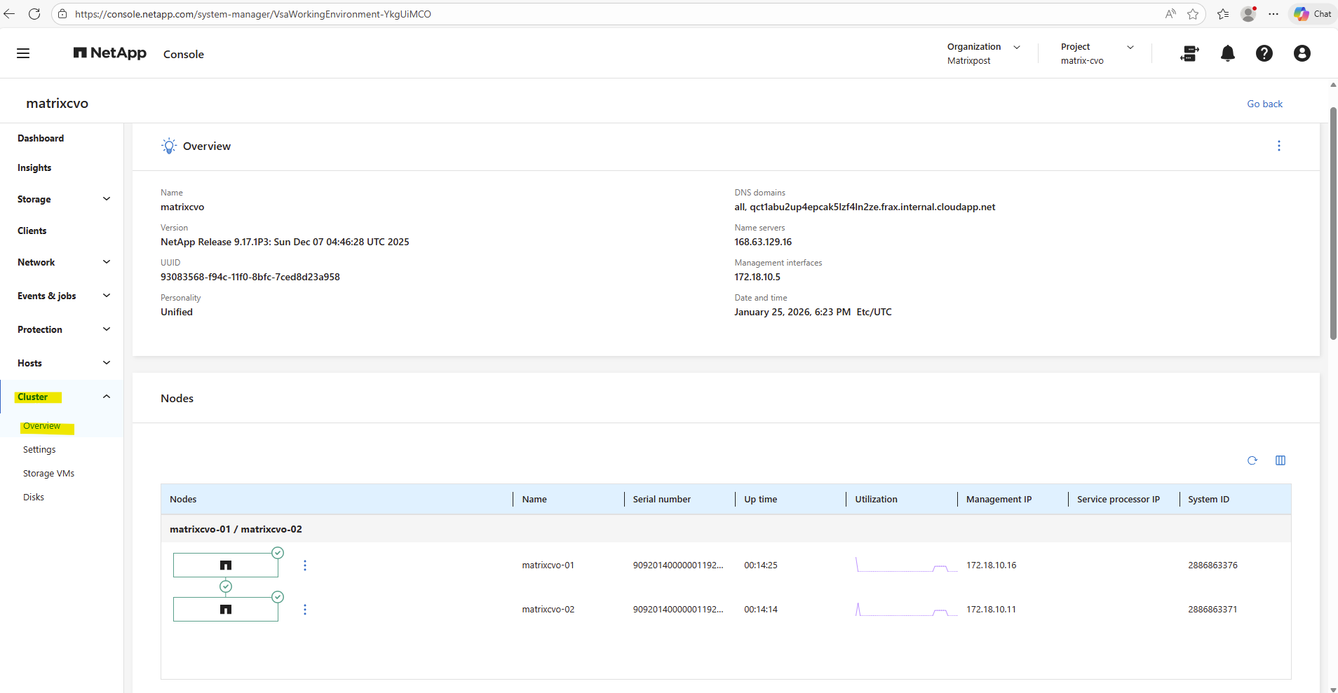
Or finally by using the ONTAP System Manager within Cluster -> Overview as shown below.
Understanding the Aggregate Layout
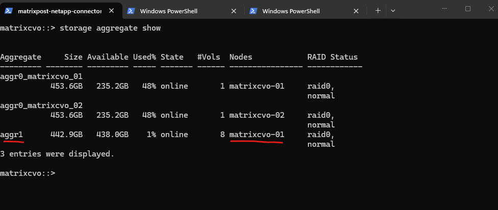
After deployment, the Cloud Volumes ONTAP system creates several aggregates automatically. As shown in the output below, each node has its own root aggregate (aggr0), which contains the ONTAP system volume and is used exclusively for internal operations.
These aggregates are not intended for user data.
In addition, a data aggregate (aggr1) is created, which is used for hosting user volumes. This aggregate is where NFS or SMB volumes will later be provisioned and is the primary storage pool for workloads
matrixcvo::> storage aggregate show
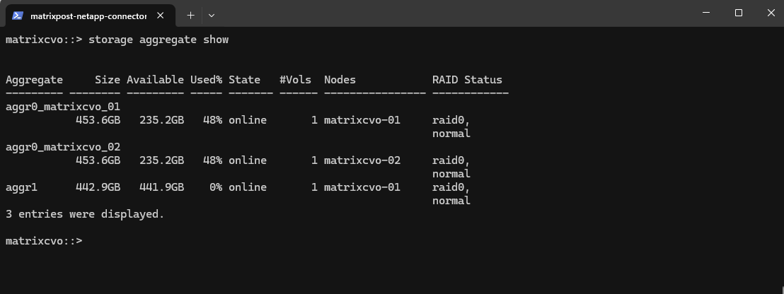
After the deployment, it’s a good idea to verify the available storage aggregates to ensure the system is ready for volume creation.
Aggregates can also be reviewed in the NetApp Console and in ONTAP System Manager, where they are displayed as Local Tiers.
This provides a quick overview of available capacity, ownership, and overall health before proceeding with further configuration.
By using the NetApp console we need to navigate to Storage -> Management -> Systems, here select our system and click on the right bar on Enter System.
By using the ONTAP System Manager we also need to navigate within the NetApp Console to Storage -> Management -> Systems, here select our system and click on the right bar for the System Manager on Open.
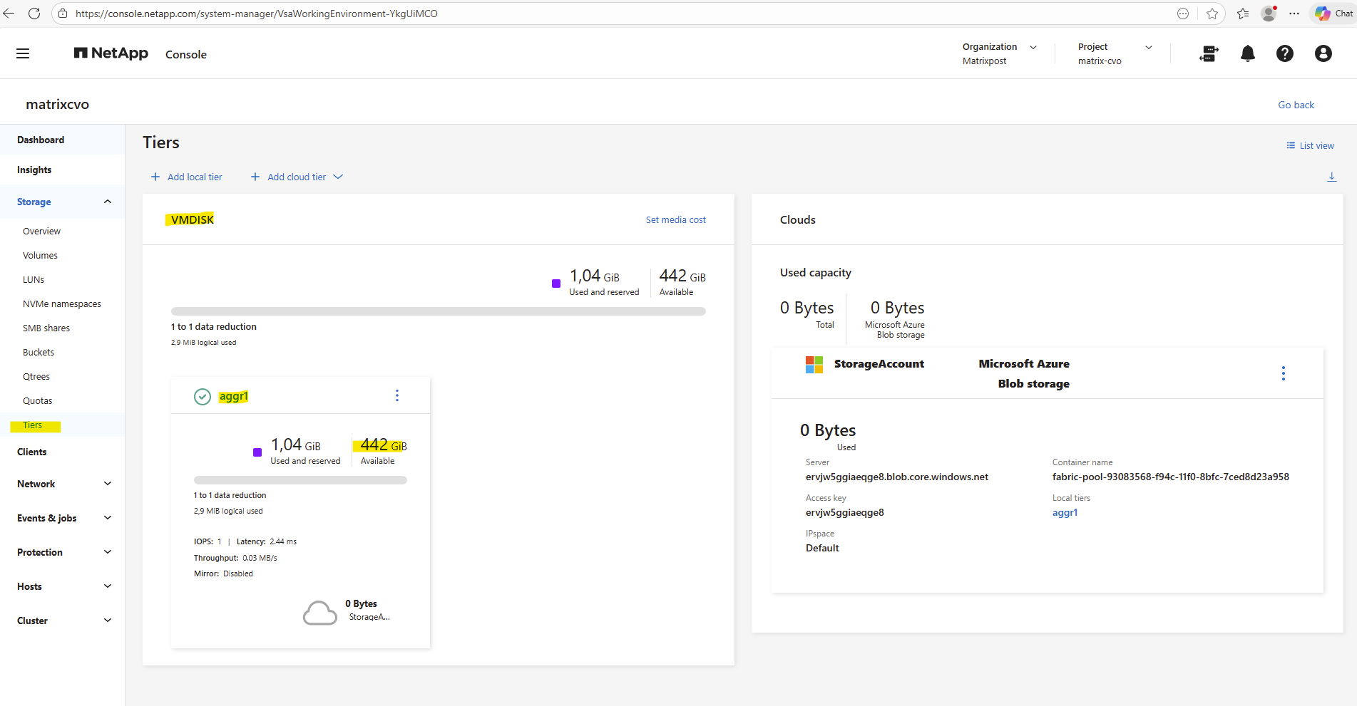
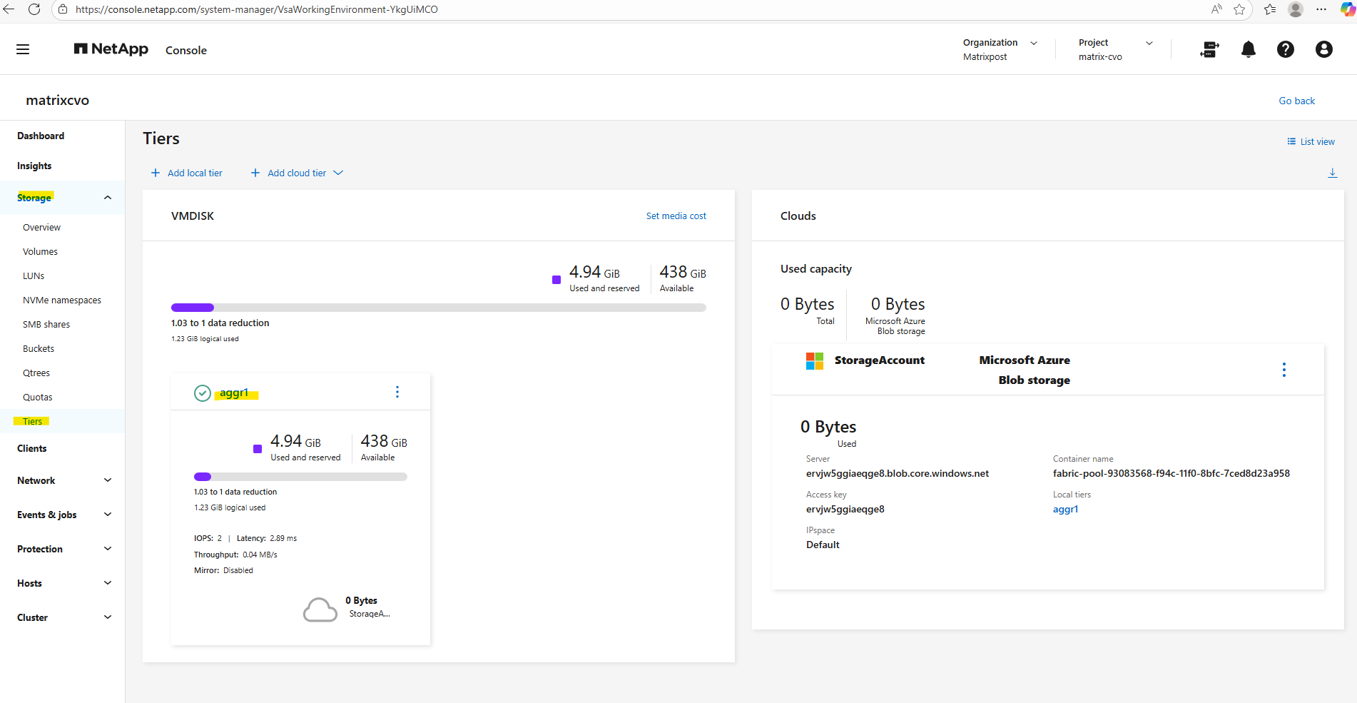
In the ONTAP System Manager the aggregates can be found under Storage → Tiers like shown below.
How Shared Disks Provide Continuous Storage Access Across Nodes
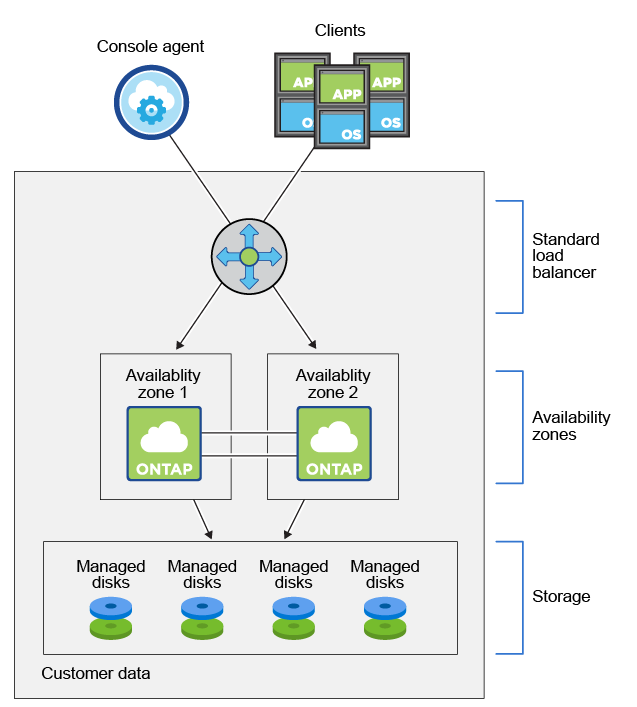
Unlike traditional single-node storage designs, Cloud Volumes ONTAP in Azure relies on shared managed disks that are simultaneously accessible by both HA nodes.
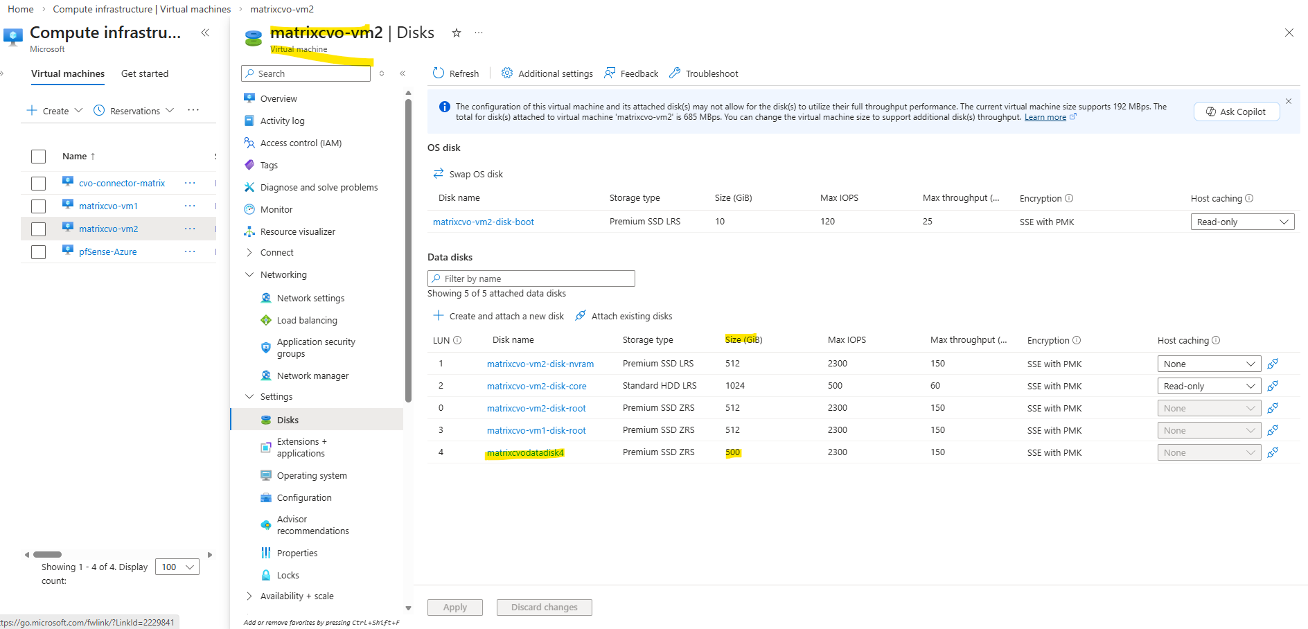
In Cloud Volumes ONTAP (CVO) running in Azure, the disks that form an aggregate are directly attached as shared Azure Managed Disks to the VM that represents the ONTAP node.
Customer data resides on Premium Storage page blobs. Each node has access to the other node’s storage. Additional storage is also required for boot, root, and core data
Boot data resides on a disk attached to the instance or virtual machine. This disk, which contains the boot image, is not available to Cloud Volumes ONTAP.
Root data, which contains the system configuration and logs, resides in
aggr0. The storage virtual machine (SVM) root volume resides inaggr1.Data volumes also reside in
aggr1.Source: https://docs.netapp.com/us-en/storage-management-cloud-volumes-ontap/concept-ha-azure.html
Share an Azure managed disk across VMs
https://learn.microsoft.com/en-us/azure/virtual-machines/disks-shared
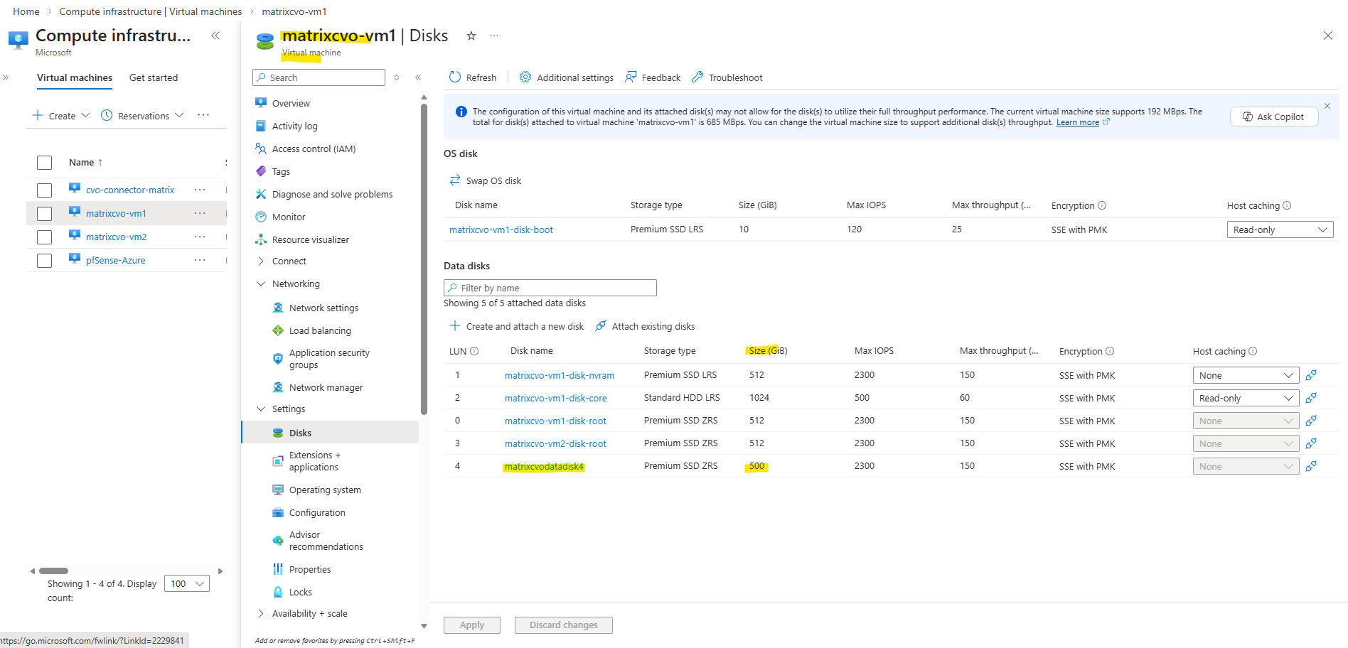
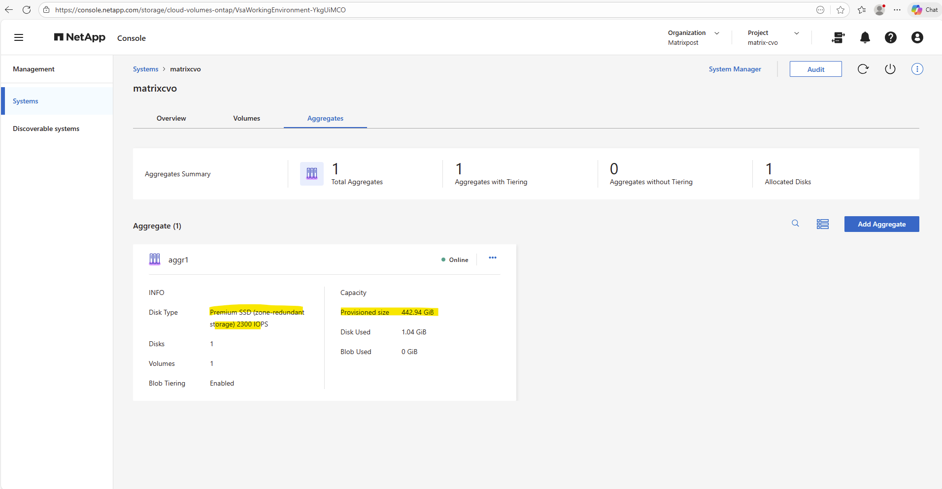
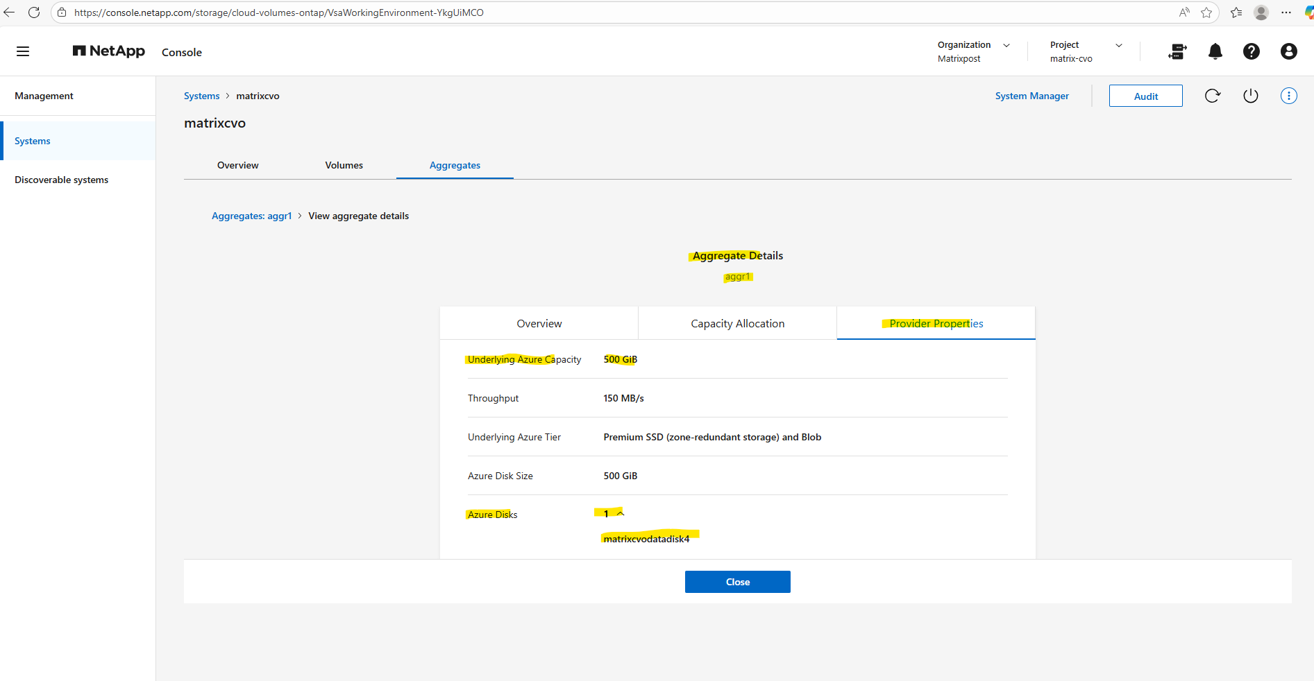
In my lab environment the
matrixcvodatadisk4with 500 GB is currently the only data aggregate disk and where provisioned during initial deployment.
Source: https://docs.netapp.com/us-en/storage-management-cloud-volumes-ontap/concept-ha-azure.html
More about Shared Azure managed disks across VMs you will find here https://learn.microsoft.com/en-us/azure/virtual-machines/disks-shared
Adding a Second Data Aggregate
To increase storage capacity or separate workloads, you can quickly add another data aggregate using the NetApp Console.
This approach allows you to expand your Cloud Volumes ONTAP system without disrupting existing volumes while maintaining the same management workflow used during the initial deployment.
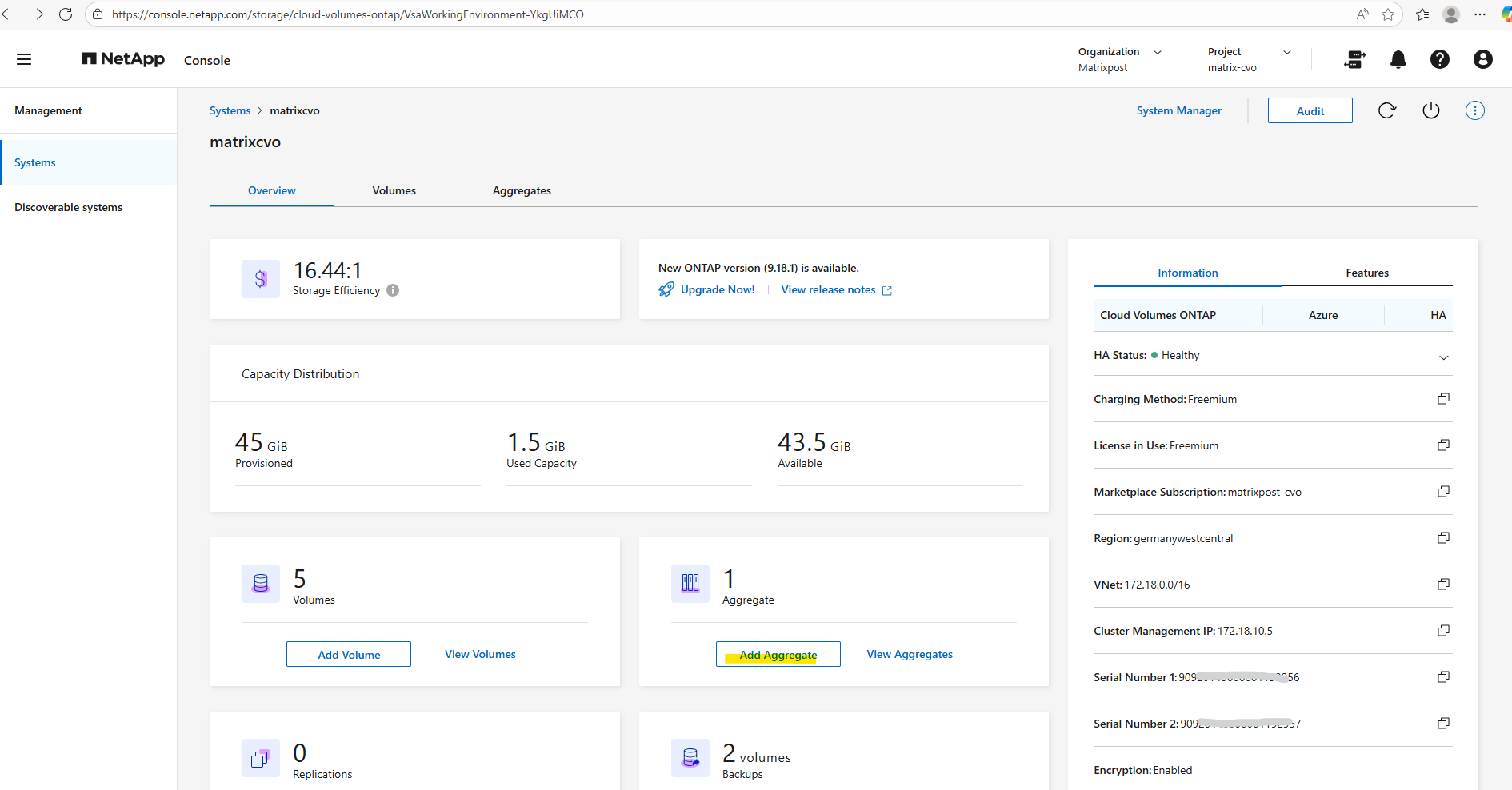
In the NetApp Console under Storage -> Management, select your CVO system and click on Enter System as shown below.
In the Systems section in the Overview tab click on Add Aggregate.
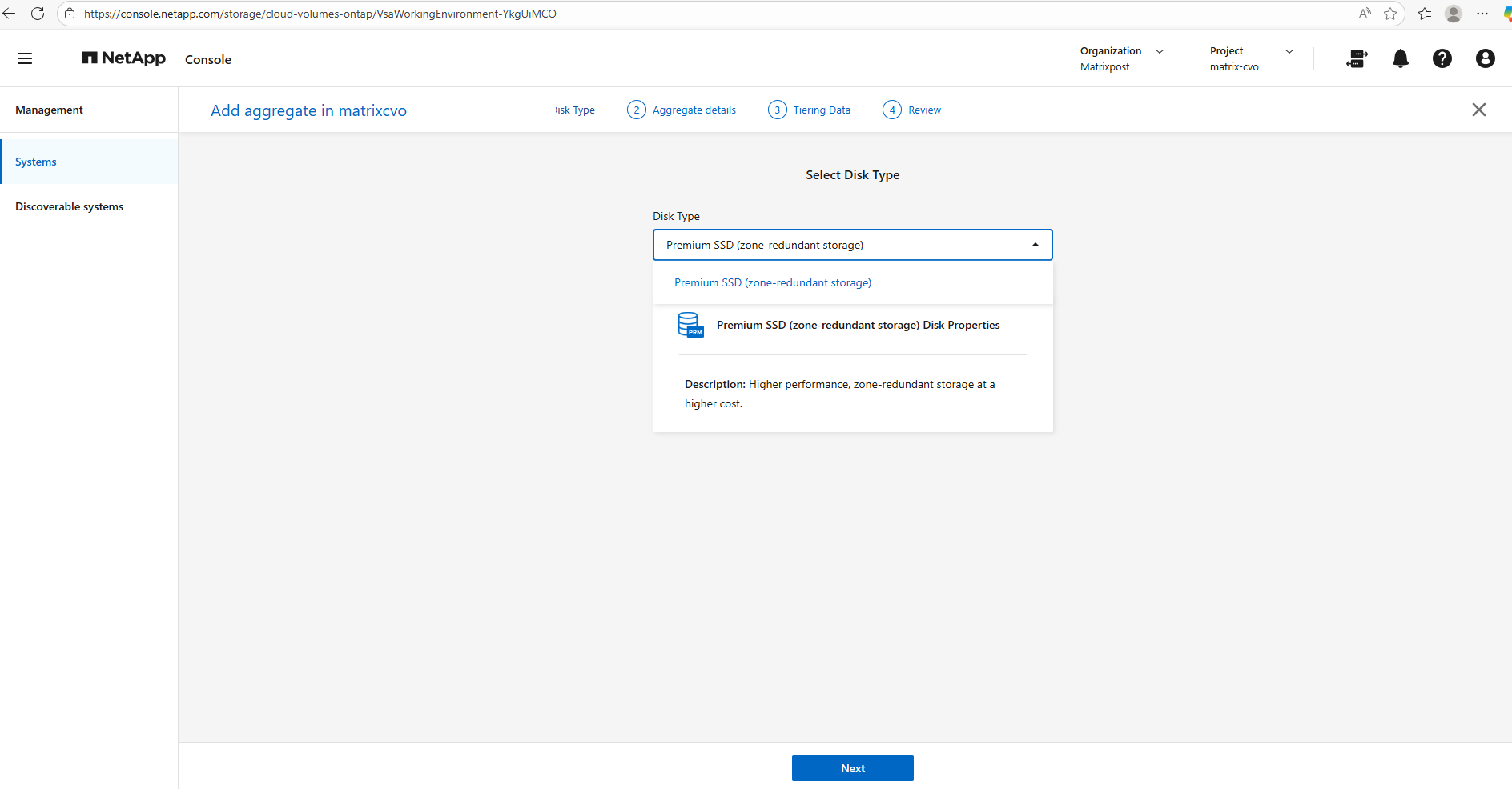
Select the disk type our new aggregate will use.
In Microsoft Azure the disk types you see when adding an aggregate in NetApp Cloud Volumes ONTAP via NetApp console are constrained by region, availability zones, and the HA deployment model.
For an Azure CVO HA pair deployed across zones, Premium SSD ZRS is often the only supported and therefore selectable option because it provides synchronous zone-level resiliency that matches the HA design.
In Part 2 I was showing how to deploy the Azure CVO HA pair and the steps where we select the region, availability zones, and the HA deployment model.
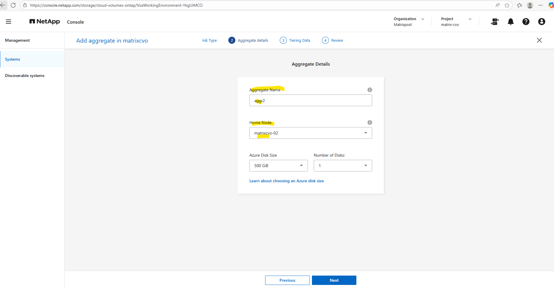
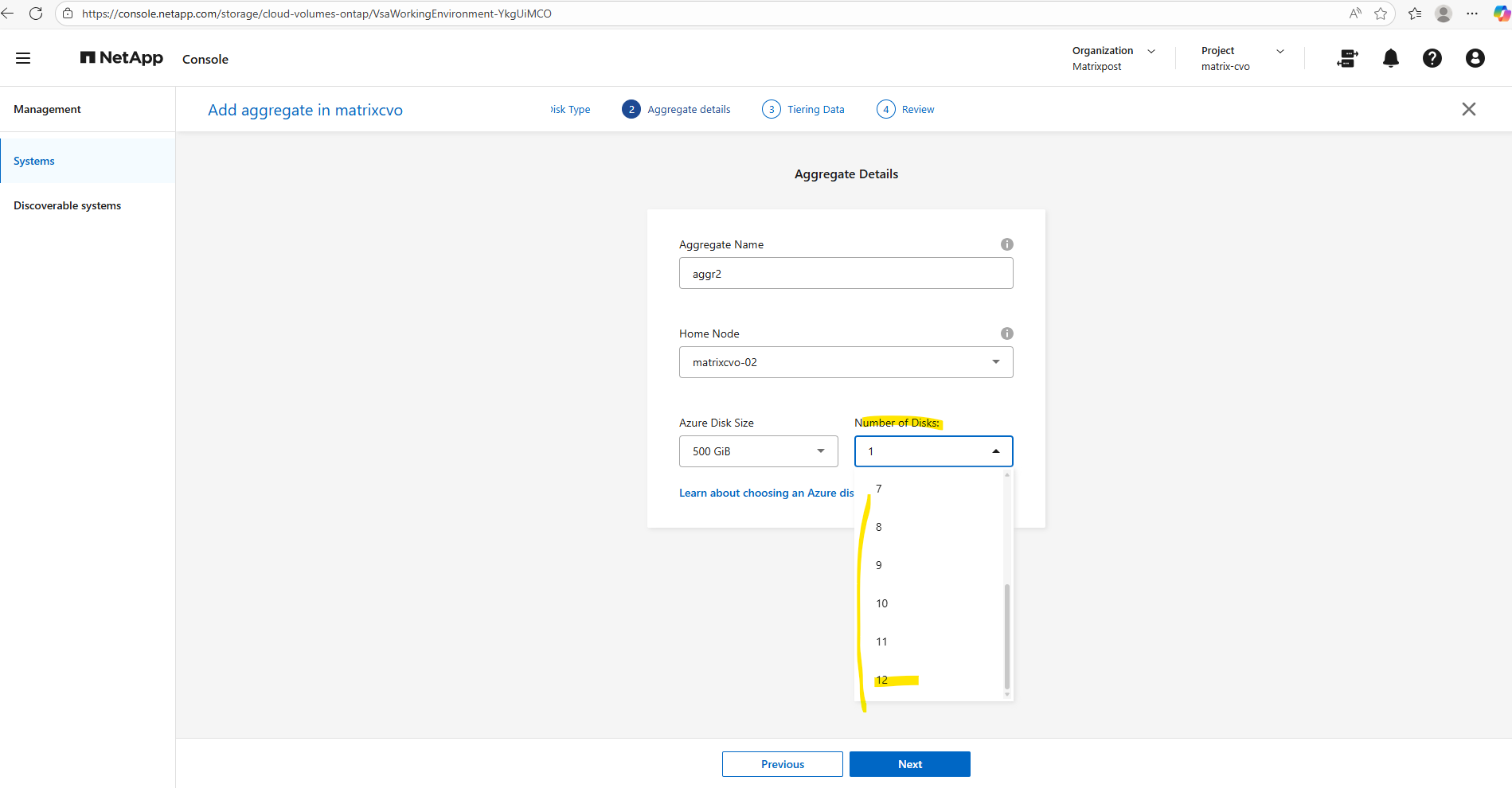
Give the new aggregate a meaningful name, since the default aggregate is aggr1, we’ll call the new one aggr2.
Next, choose the home node: because aggr1 already belongs to node 1, we deliberately place aggr2 on node 2 to balance ownership across the HA pair.
In a NetApp Cloud Volumes ONTAP HA setup, the recommended practice is to distribute aggregates evenly across both nodes.
Each node should own at least one aggregate so that normal operation already leverages both nodes, avoids asymmetric performance, and keeps takeover/giveback behavior predictable. Volumes can live on any aggregate regardless of node, but aggregate ownership determines where the I/O is serviced in steady state, so spreading aggregates across nodes is the clean, support-friendly design.
We can always verify aggregate ownership directly on the CLI with:
matrixcvo::> storage aggregate show
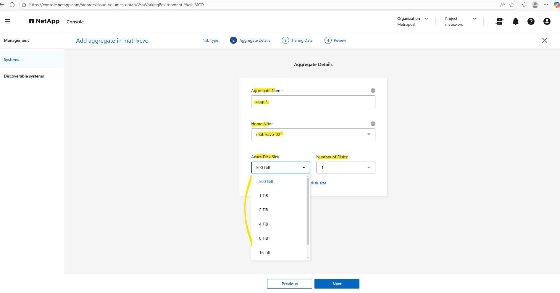
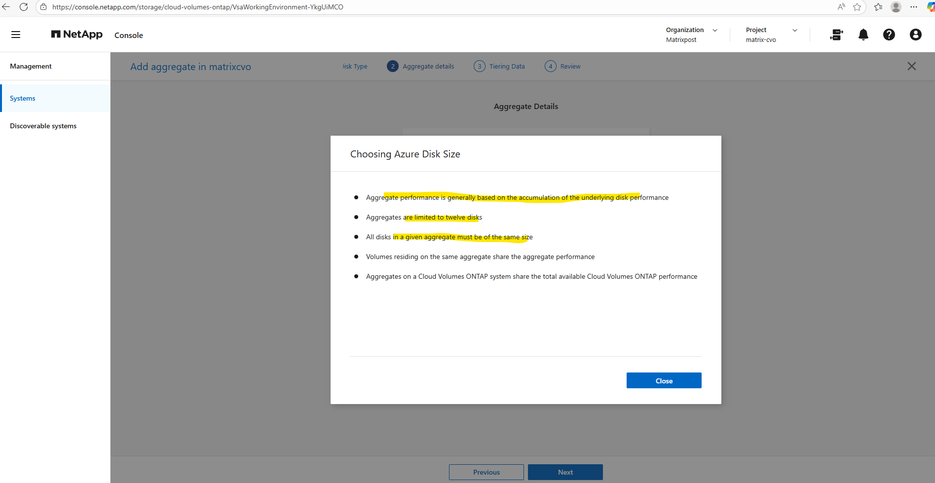
When you create a new aggregate in NetApp Cloud Volumes ONTAP, the disk size is fixed at creation time and cannot be changed later. You can grow the aggregate by adding more disks of the same size, but you can’t resize existing disks or mix different disk sizes within the same aggregate. If you need a different disk size, the supported approach is to create a new aggregate with the desired size and move volumes there.
Disk size and disk count together define both the capacity and performance of an aggregate.
Single node and HA systems which use managed disks have a maximum of 32 TiB per disk. The number of supported disks varies by VM size.
Larger disks provide more usable space, while a higher number of disks increases throughput and IOPS by allowing ONTAP to stripe data across more underlying storage.
As a best practice, avoid the minimum disk configuration and aim for similarly sized aggregates across both nodes to maintain balanced performance in the HA pair.
To see which VM size supports max data disks per node you can read the following article https://docs.netapp.com/us-en/cloud-volumes-ontap-relnotes/reference-limits-azure.html#disk-and-tiering-limits-by-vm-size.
In my case I will use for my lab environment the smallest size with E8ds_v4 in multiple availability zones with shared managed disks, so I can adding max 12 data disks.
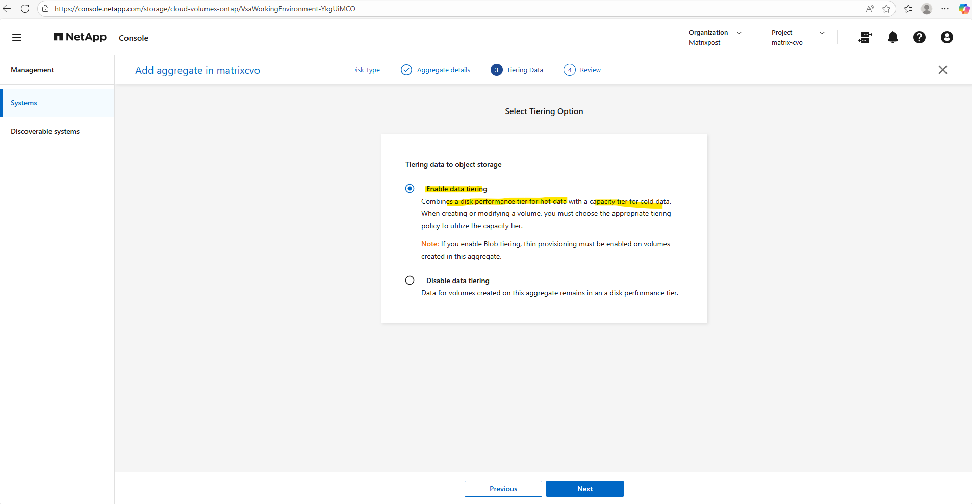
Tiering data to object storage allows Cloud Volumes ONTAP to automatically move cold data blocks from the performance tier to low-cost object storage, reducing overall storage costs while keeping hot data on fast disks.
With Enable data tiering, inactive data is transparently offloaded based on the configured tiering policy, whereas Disable data tiering keeps all data permanently on the performance tier, which can be useful for latency-sensitive or consistently active workloads.
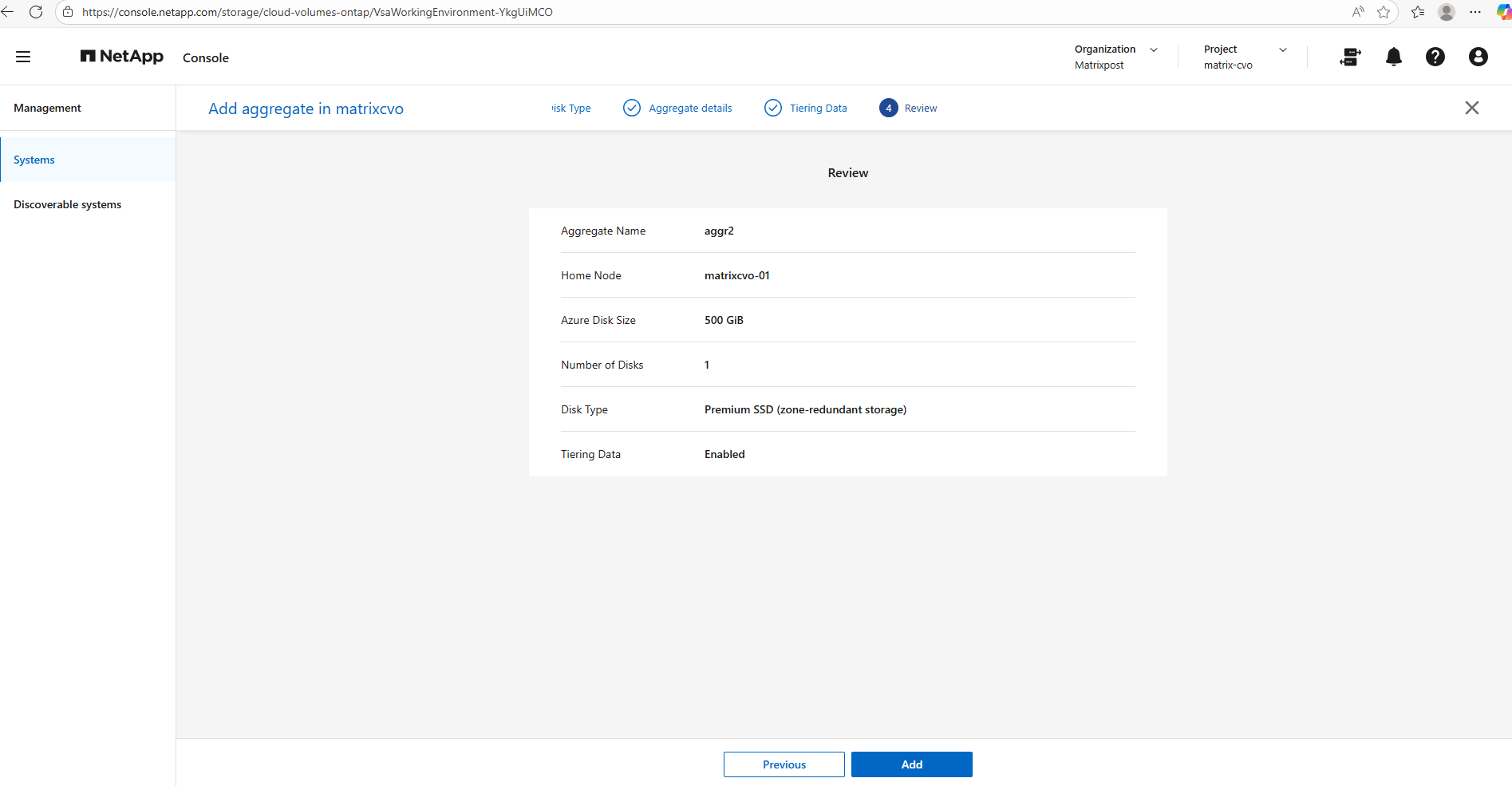
The final summary page provides a consolidated view of your configuration before provisioning the aggregate,once you click Add, the deployment starts immediately.
Since adding another aggregate would exceed the limits of the FREEMIUM license and automatically convert the system to a paid tier, I will stop here and not proceed with the creation. This is a good checkpoint to review licensing implications before committing changes that could trigger additional costs.
Expanding an Aggregate by Adding Disks
As storage demands grow, you don’t always need to create a new aggregate, you can seamlessly scale an existing one by adding more disks.
This approach increases both available capacity and potential performance without changing the overall layout of your storage design.
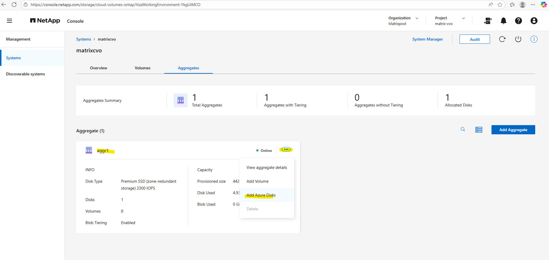
In the Systems section on the Overview tab, similar to when adding a new aggregate, click View aggregate to open the aggregate details.
Locate the aggregate you want to expand, click the three-dot menu, and select Add Azure disks from the context menu, as shown below.
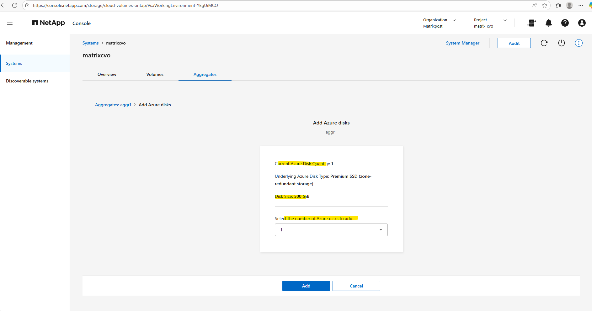
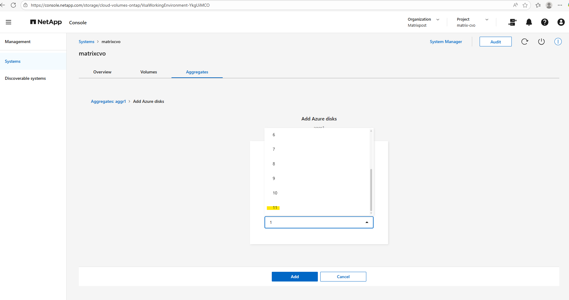
Since my lab environment uses the default FREEMIUM configuration with one 500-GB disk, I can add up to 11 additional disks, the maximum number of disks per aggregate is 12.
I won’t click Add here, because just like when creating an additional aggregate, this would exceed the FREEMIUM license and automatically switch the system to a paid tier.
From an operational perspective, adding disks to an existing aggregate is a non-disruptive operation: ONTAP expands the aggregate online while volumes remain accessible. It’s a safe, in-place scaling method that doesn’t require downtime or client-side changes.
Data Tiering (Blob Tiering)
Data tiering, often referred to as blob tiering in Azure, is a core capability of FabricPool that automatically moves cold data from high-performance disks to cost-efficient object storage.
By keeping frequently accessed data on the performance tier while transparently offloading inactive blocks to Azure Blob, organizations can significantly optimize storage costs without sacrificing workload performance.
Understanding how tiering works is essential for designing a storage architecture that scales efficiently while maintaining predictable latency for active data.
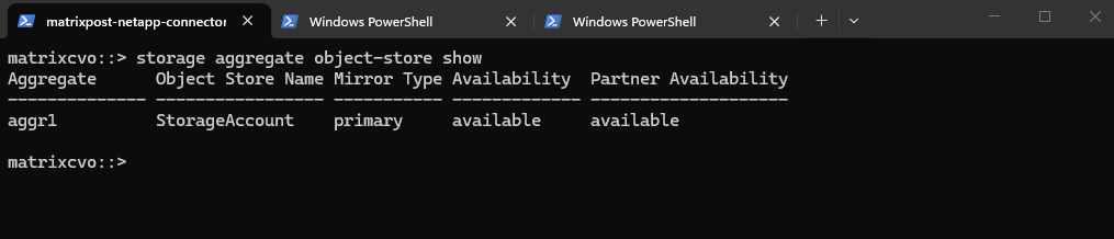
The storage aggregate object-store show command verifies that an aggregate is successfully attached to an object store, confirming that FabricPool tiering is available and operational for volumes hosted on that aggregate.
The aggregate is attached to Azure Blob (object store) and is reachable.
matrixcvo::> storage aggregate object-store show
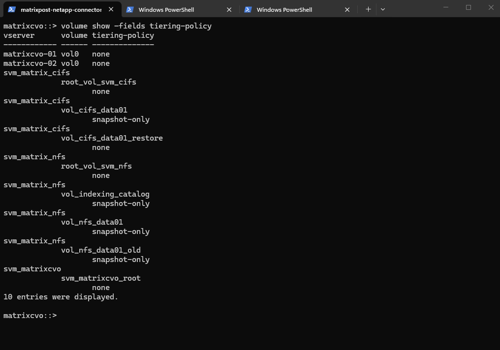
The volume show -fields tiering-policy command provides a quick overview of the tiering configuration for all volumes, allowing you to immediately identify which volumes can offload cold data to object storage and which remain fully on the performance tier.
The
snapshot-onlytiering policy allows ONTAP to move only cold Snapshot blocks to the capacity tier (e.g., Azure Blob in CVO), while all active filesystem data remains on the performance tier.
matrixcvo::> volume show -fields tiering-policy
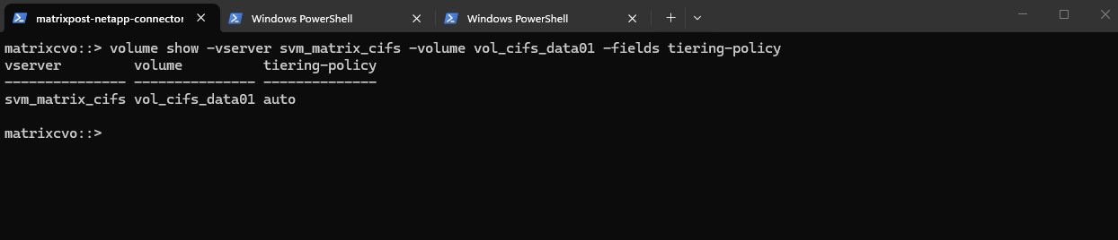
Or verify the tiering poliy for a specific volume.
The
autotiering policy allows ONTAP to automatically manage data placement by moving cold user data blocks and snapshots from expensive Azure SSDs to low-cost Azure Blob storage based on access patterns.
matrixcvo::> volume show -vserver svm_matrix_cifs -volume vol_cifs_data01 -fields tiering-policy
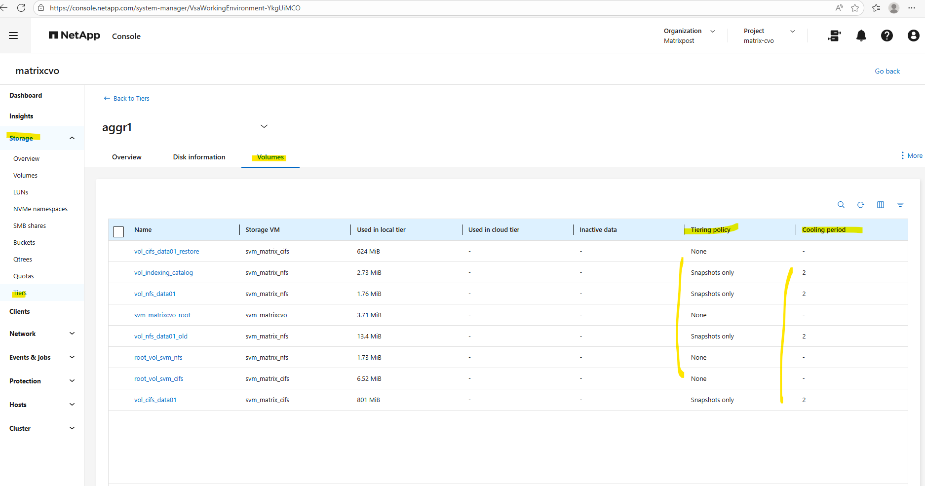
We can also use the ONTAP System Manager to verify data tiering and modifying tiering policies.
Within Storage -> Tiers -> Click on the aggregate.
Select the Volumes tab.
The cooling period defines the number of days a data block must remain inactive (aka cooled) before the
autotiering policy marks it as cold and moves it to Azure Blob storage.By setting this to a value like 2 days, you ensure that only truly stagnant data is offloaded, preventing “thrashing” where blocks are prematurely moved to the capacity tier only to be immediately pulled back when a user accesses them again.
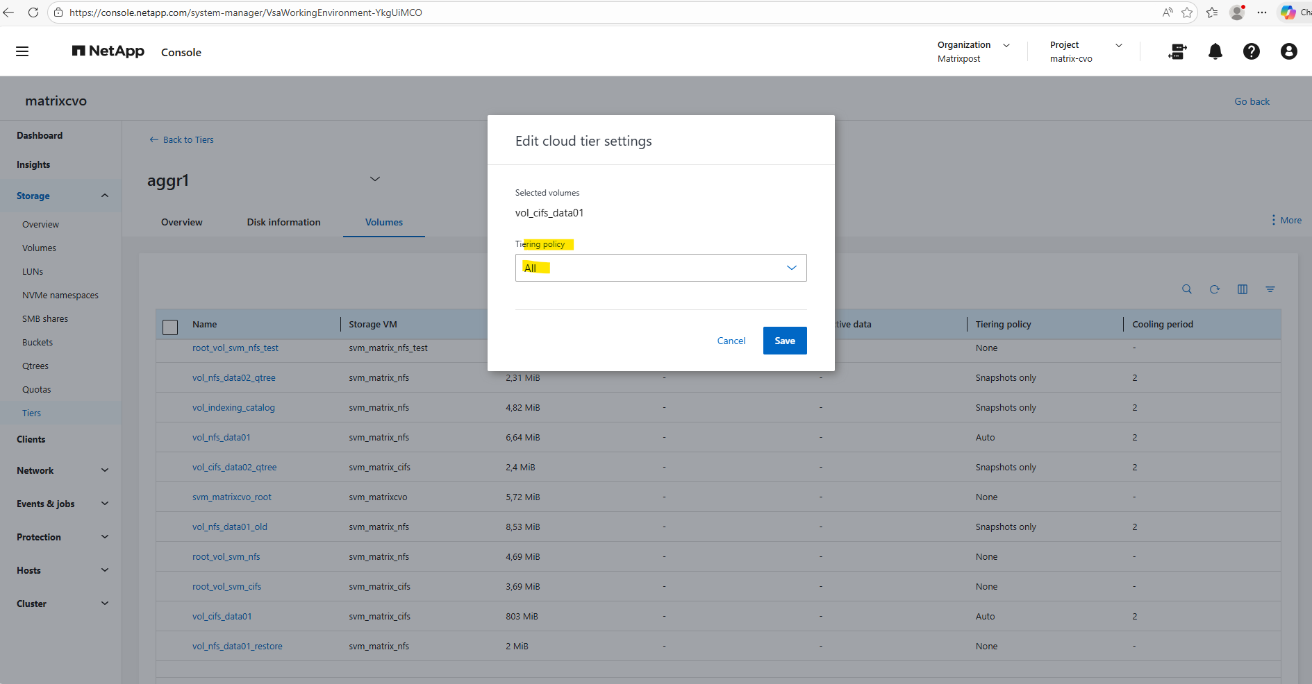
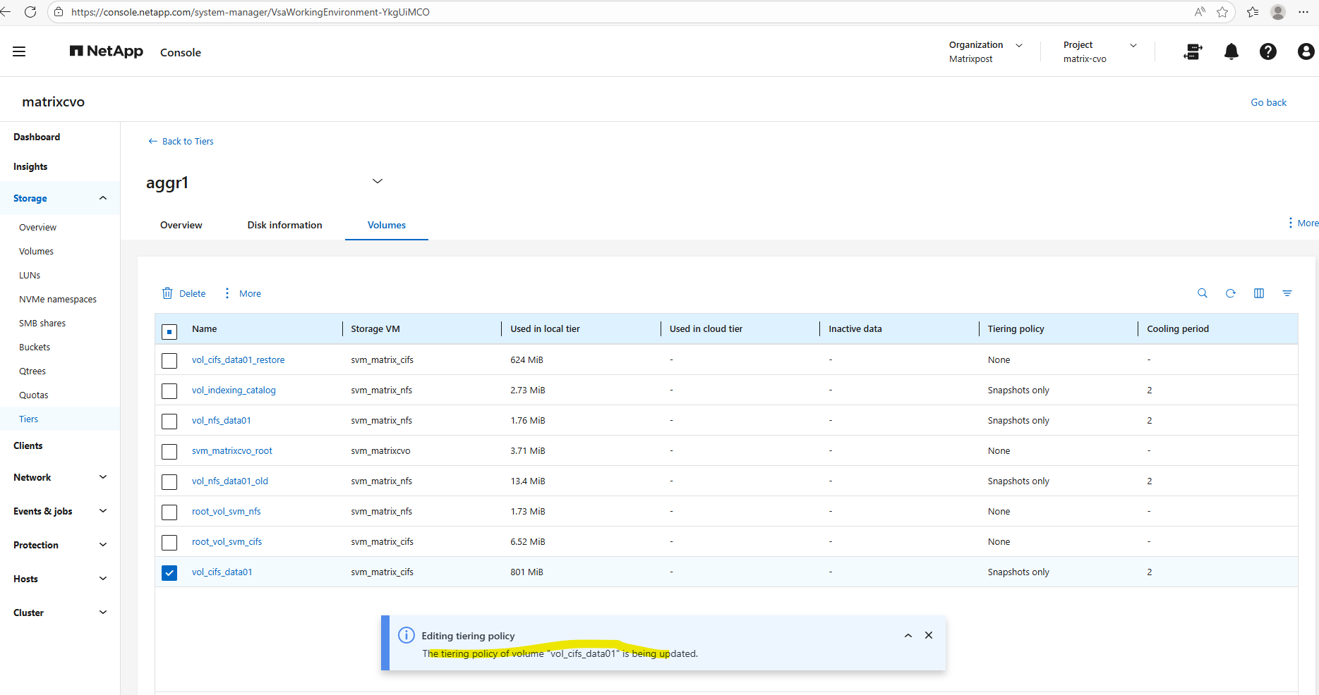
To edit the tiering policy below, check the desired volume, click on the three dots and select Edit cloud tier settings in the context menu.
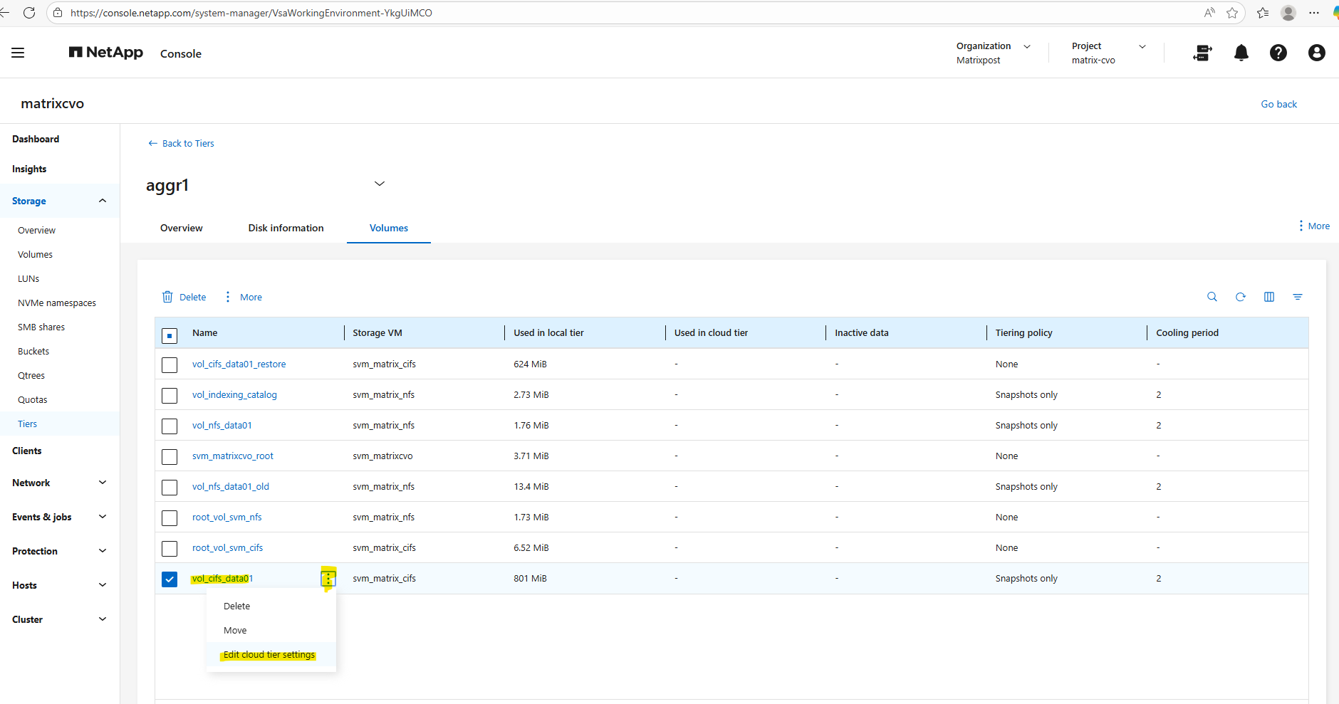
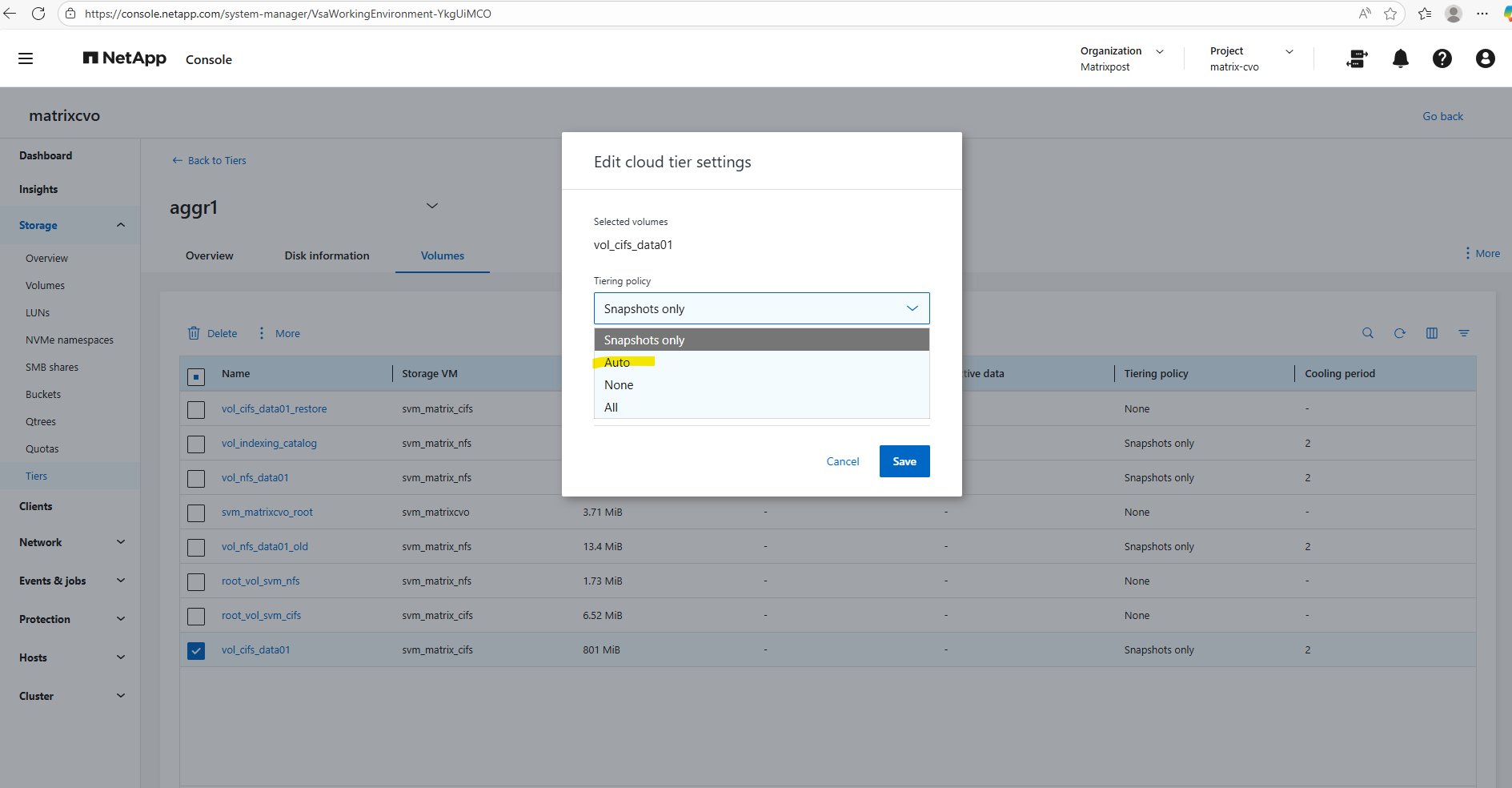
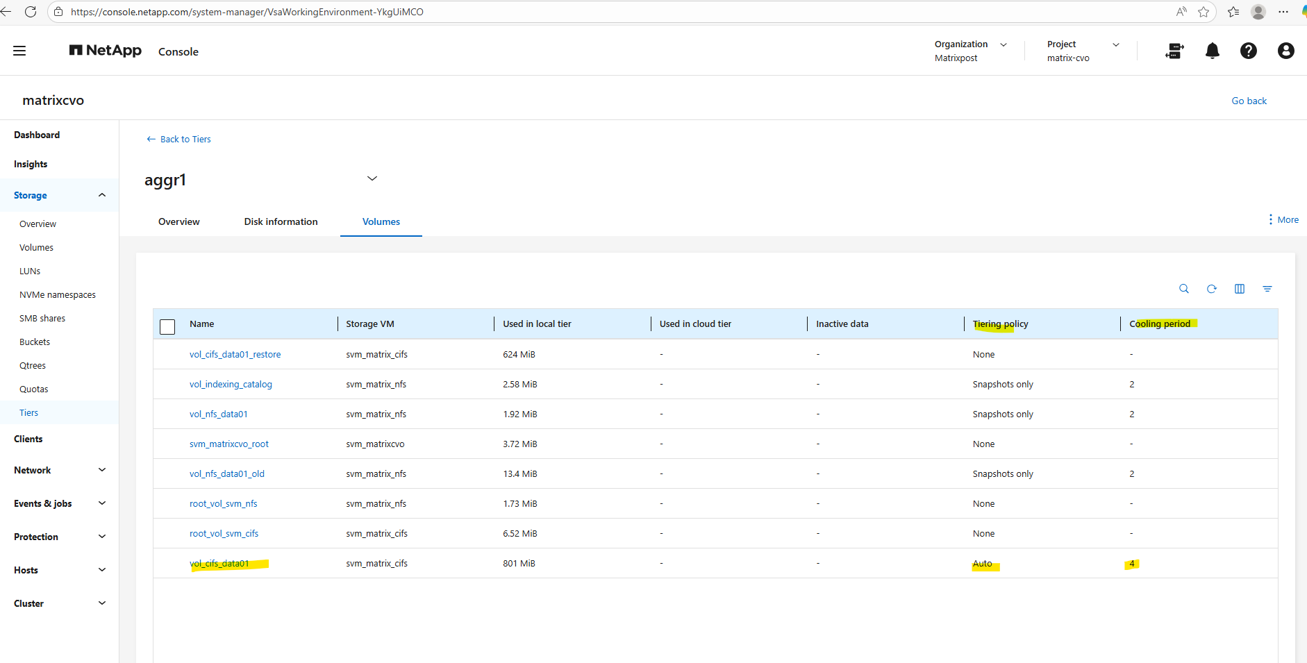
Below I will set the tiering policy for the cifs volume to Auto.
Using the
autotiering policy allows ONTAP to move both cold Snapshot data and cold user data from the performance tier to the capacity tier (Azure Blob inCVO).Only blocks that have not been accessed for the defined cooling period are tiered, while active data remains on the performance disks, ensuring no impact to hot workloads.
This policy provides the best balance between performance and cost efficiency and is typically the recommended choice for large file shares and general-purpose data volumes in Cloud Volumes ONTAP.
all(The Maximum Saver): This policy marks all data blocks in the volume as “cold” immediately, regardless of when they were last accessed. It bypasses the cooling period and attempts to move everything to the capacity tier as soon as possible, which is ideal for archives or backup targets where you don’t expect any regular read activity.
The minimum number of days that the user data blocks of the volume should be cooled before they can be considered cold and tiered to the cloud tier.
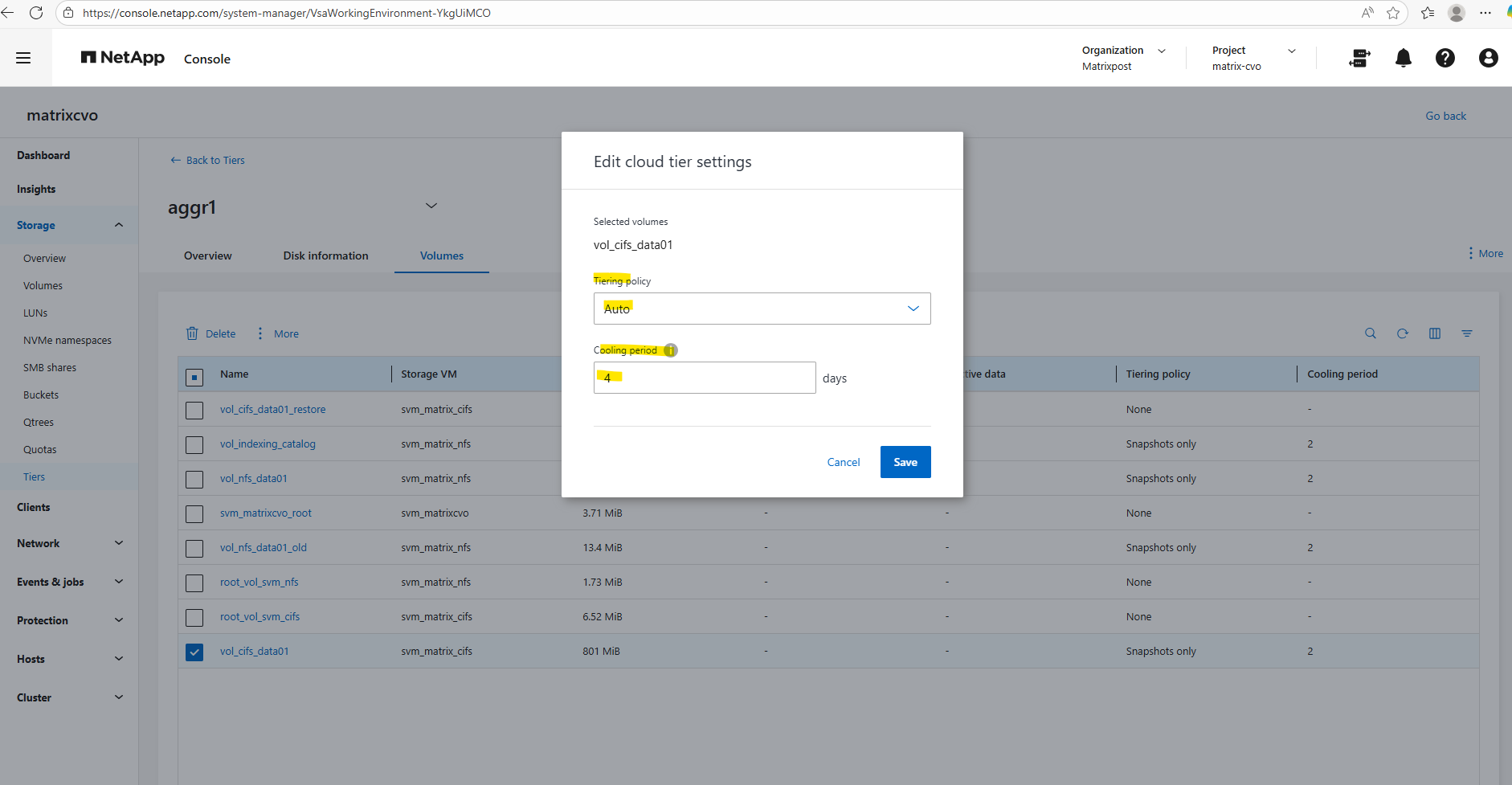
As mentioned above, when selecting All for the tiering policy, it bypasses the cooling period and attempts to move everything to the capacity tier as soon as possible.
Therefore we can’t enter a cooling period here.
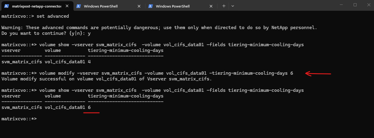
Verify the cooling period for a specific volume by using the CLI.
matrixcvo::> set advanced
matrixcvo::*> volume show -vserver svm_matrix_cifs  -volume vol_cifs_data01 -fields tiering-minimum-cooling-days
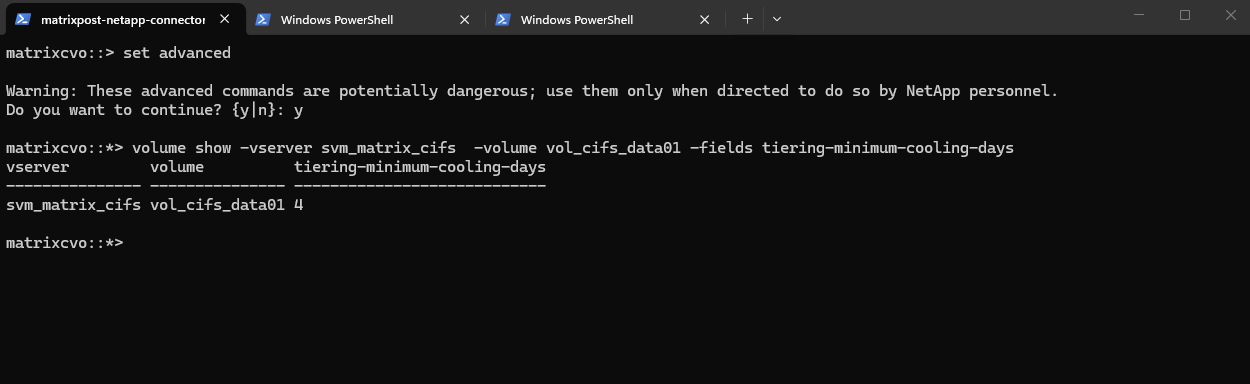
To modify the cooling days we can run the following command.
matrixcvo::> set advanced
matrixcvo::*> volume modify -vserver svm_matrix_cifs -volume vol_cifs_data01 -tiering-minimum-cooling-days 6

# verify the modification
matrixcvo::*> volume show -vserver svm_matrix_cifs  -volume vol_cifs_data01 -fields tiering-minimum-cooling-days
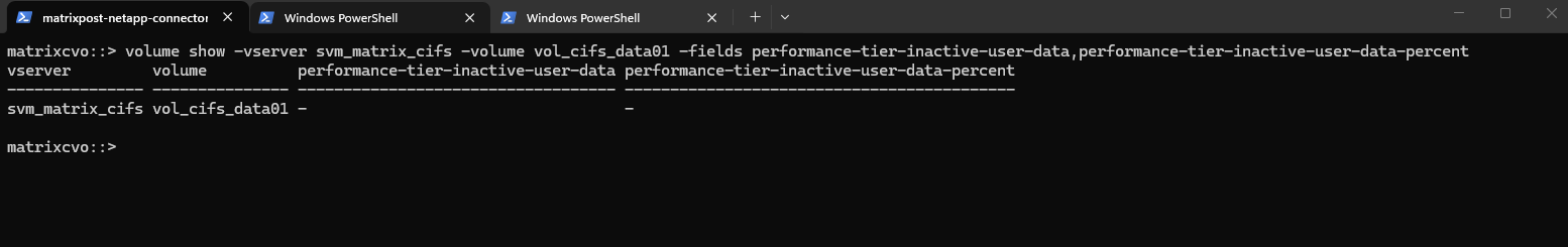
The performance-tier-inactive-user-data and performance-tier-inactive-user-data-percent fields show how much cold data has been identified on the performance tier and is eligible to be moved to the capacity tier.
These metrics help you quickly assess potential storage savings and evaluate how effectively FabricPool is optimizing your tiered storage.
matrixcvo::> volume show -vserver svm_matrix_cifs -volume vol_cifs_data01 -fields performance-tier-inactive-user-data,performance-tier-inactive-user-data-percent
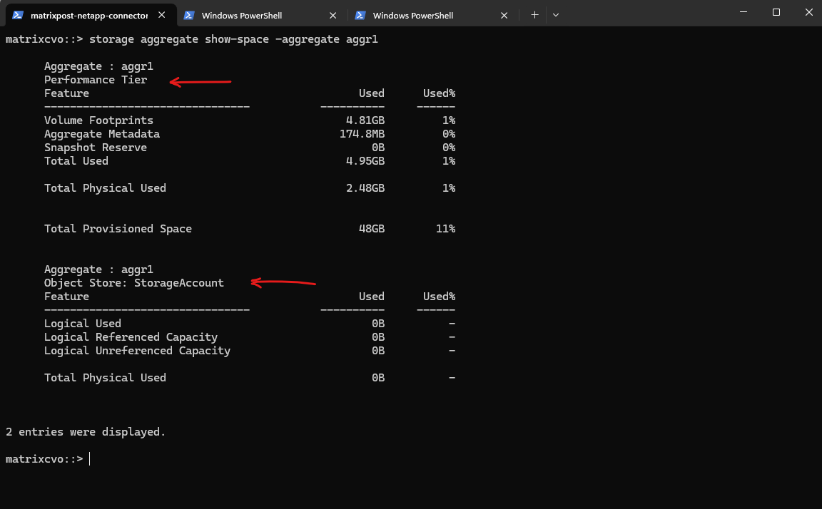
The storage aggregate show-space command provides a detailed breakdown of capacity usage across both the performance tier and the object tier, allowing you to clearly see how storage is consumed within a FabricPool aggregate.
A FabricPool aggregate is an ONTAP aggregate that is connected to an object store (such as Azure Blob, AWS S3, or StorageGRID), enabling automatic tiering of cold data from high-performance disks to cost-efficient object storage. By combining a local performance tier with a cloud-based capacity tier, FabricPool helps optimize storage costs while keeping frequently accessed data on fast media.
StorageGRID is NetApp’s software-defined object storage platform that provides an S3-compatible capacity tier for FabricPool and other data services. It is typically deployed on-premises or in private cloud environments to deliver scalable, durable, and cost-efficient storage for long-term data retention.
matrixcvo::> storage aggregate show-space -aggregate aggr1
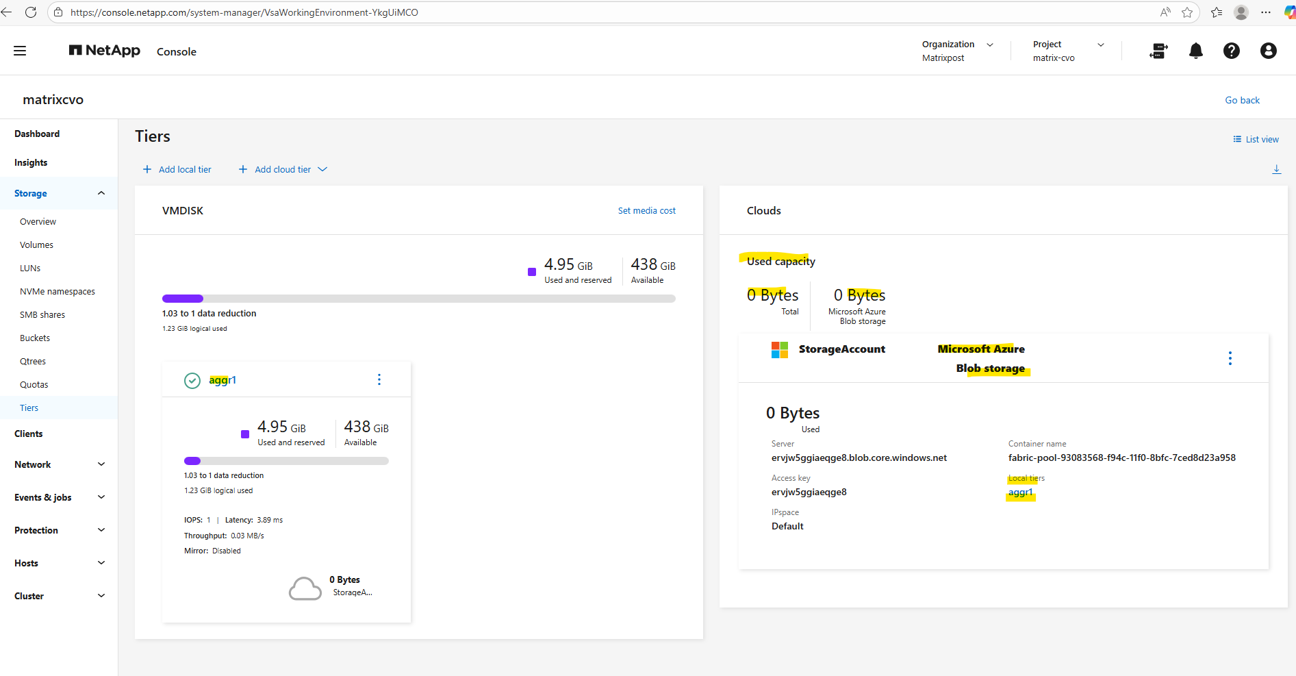
The capacity usage across both the performance tier and the object tier we can also obtain using the ONTAP System Manager within Storage -> Tiers as shown below.
Create a Storage Virtual Machine (SVM)
A Storage Virtual Machine (SVM) is a core concept in NetApp ONTAP and is key to its multi-tenant, multi-protocol, and software-defined design.
A Storage Virtual Machine (SVM) is a secure, isolated namespace and management domain that provides access to storage resources (volumes, LIFs, etc.) within a NetApp cluster.
You can think of an SVM as a “virtual NAS/SAN controller” inside a physical ONTAP cluster.
For my lab environment using the NetApp Freemium license I can create max 24 storage VMs total.
Before creating any volumes, we must first create a Storage Virtual Machine (SVM). The SVM acts as the logical container for storage and defines which protocols (NFS, SMB, iSCSI) are available, along with networking, security, and access settings.
Only after an SVM exists can you create volumes, as volumes always belong to an SVM and inherit its protocol and access configuration.
Before creating any storage, I’ll first take a look at the freshly deployed Cloud Volumes ONTAP system to see whether a data SVM is already in place by running the following command.
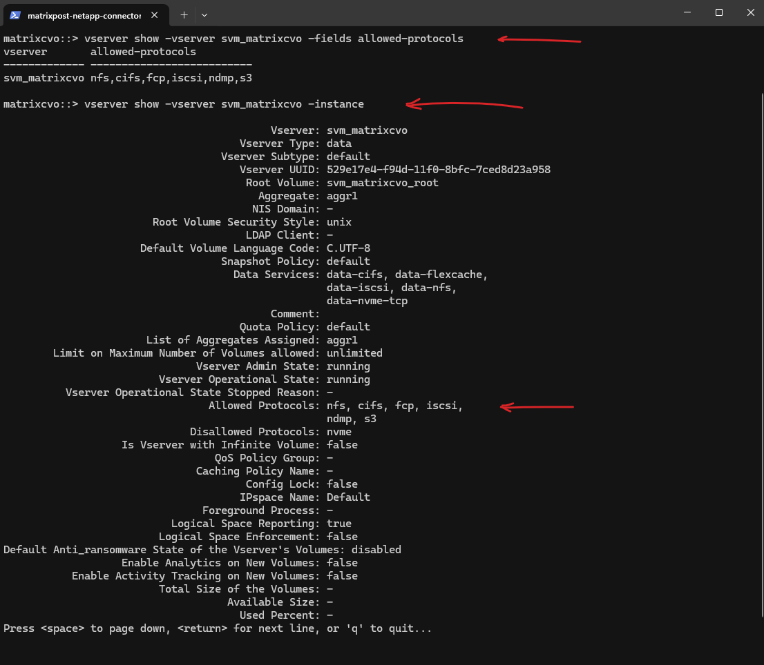
matrixcvo::> vserver show
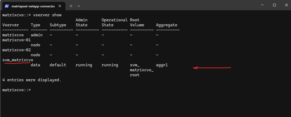
After deployment, the Cloud Volumes ONTAP system already contains a preconfigured data SVM shown below and named svm_matrixcvo.
This SVM is used to host storage volumes and provide access via NFS or SMB.
Since the SVM is already running and assigned to the data aggregate, no additional SVM creation is required before creating the first volume.
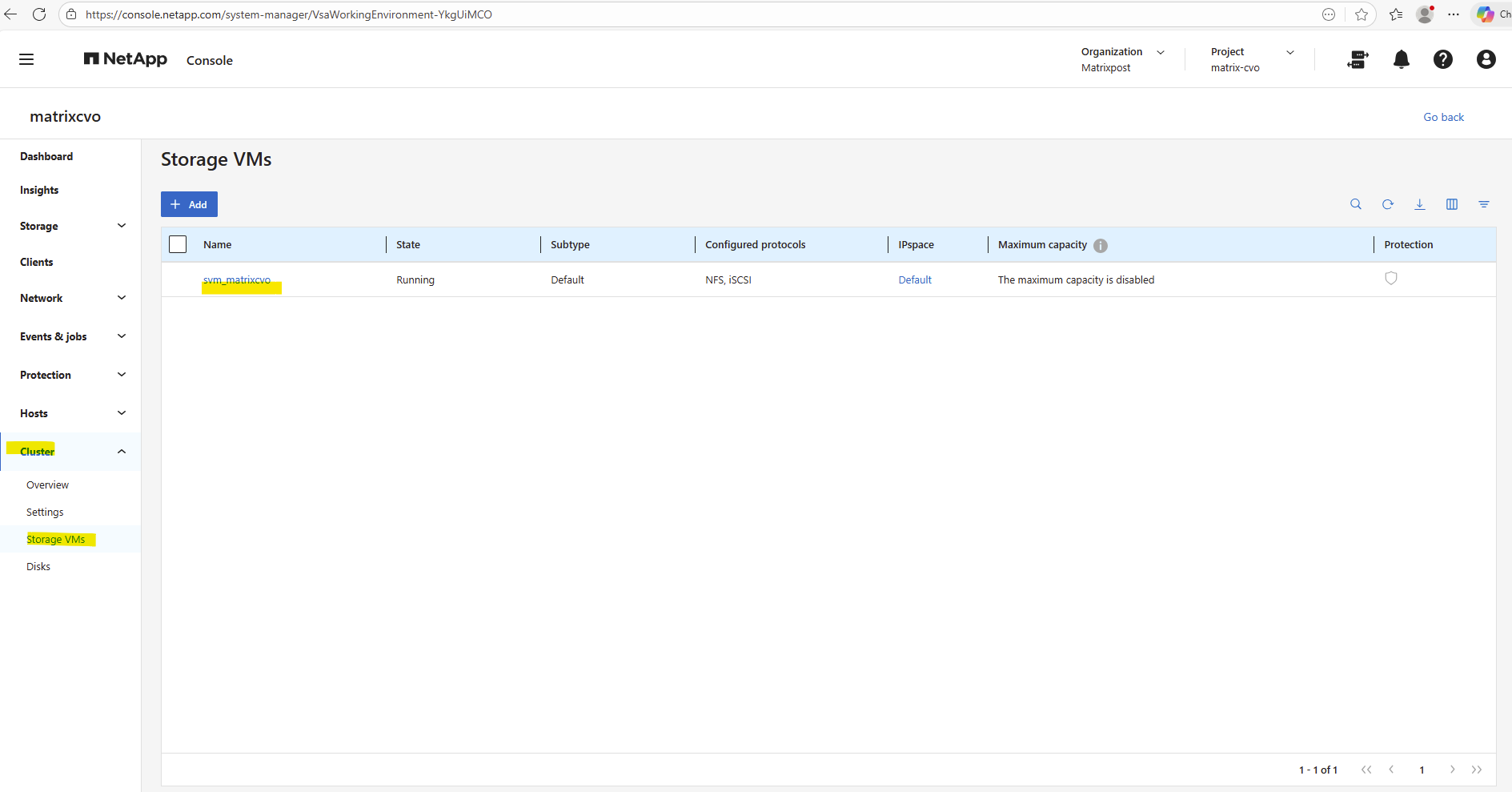
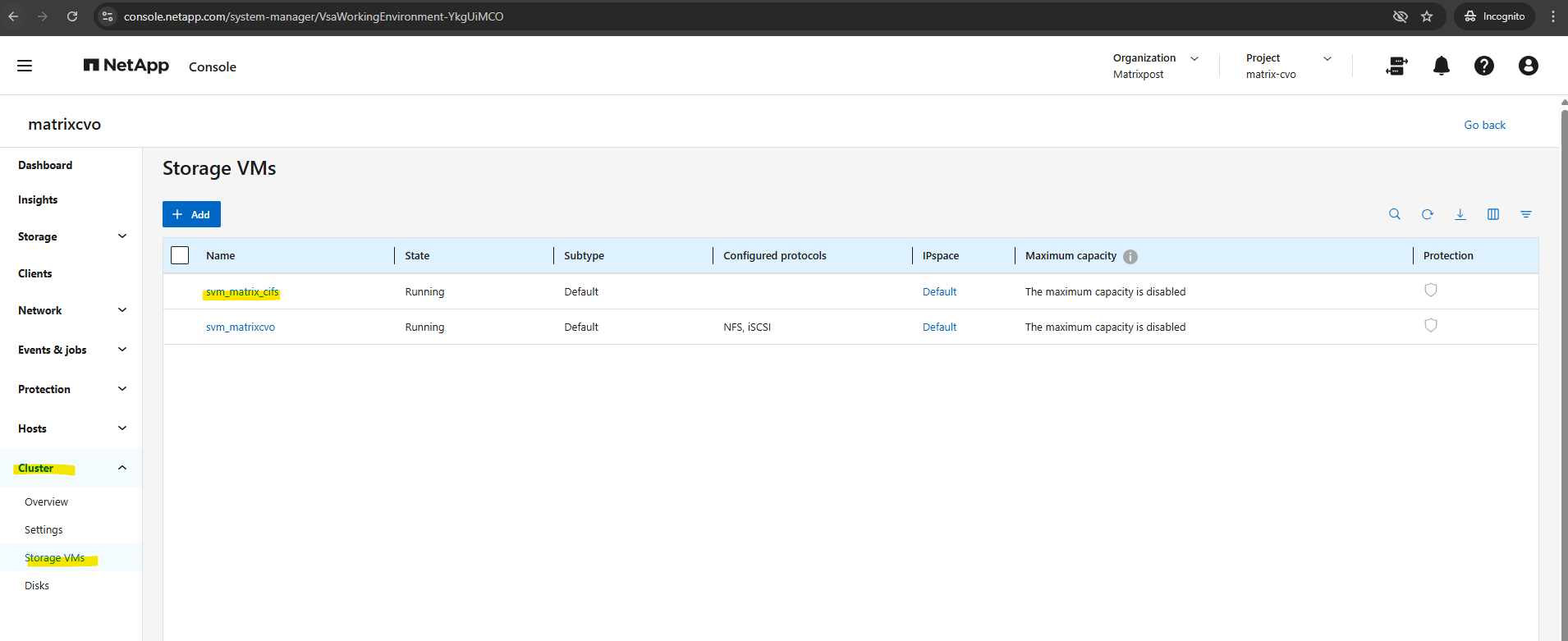
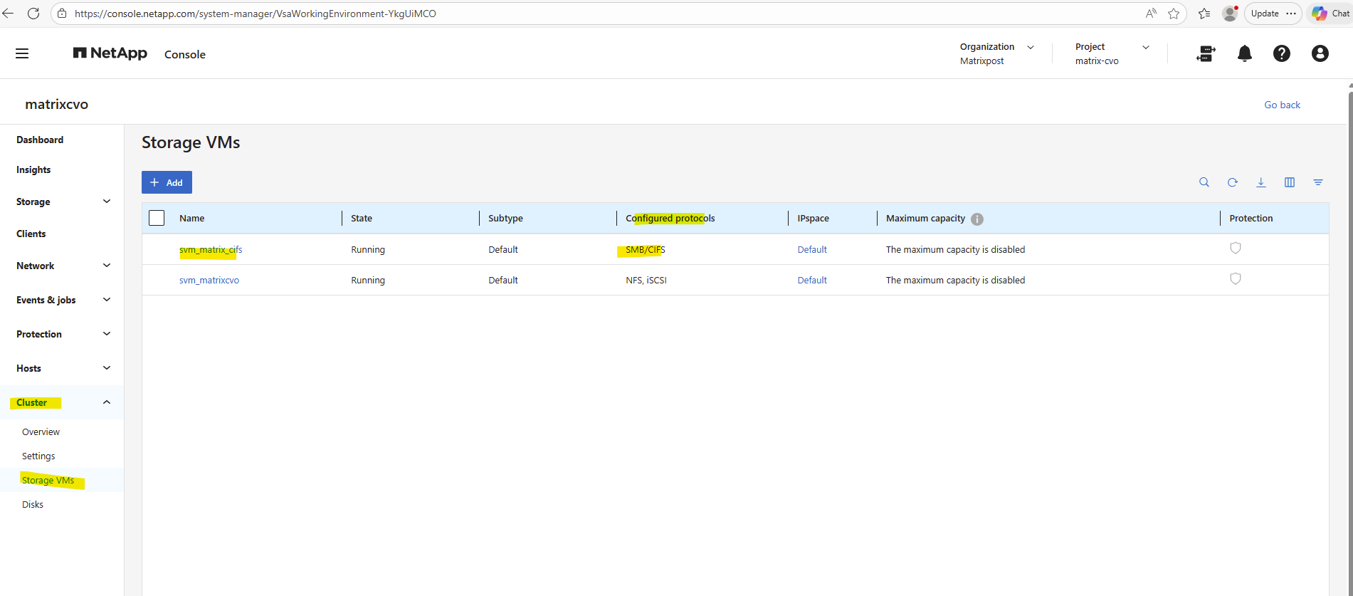
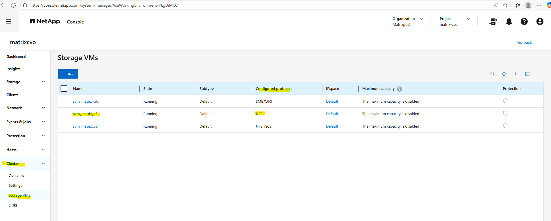
The already preconfigured data SVM we can also see in the ONTAP System Manager under Cluster -> Storage VMs.
To ensure clean separation of protocols, security contexts, and authentication domains, we need to create further several SVMs like a dedicated for cifs/SMB shares and a dedicated for NFS shares (exports).
We will now create a Storage Virtual Machine (SVM), then a volume on our new aggregate, and finally enabling access via CIFS (SMB) and/or NFS.
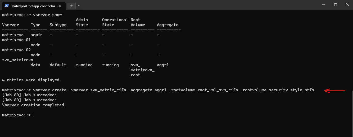
To create a new storage VM execute.
matrixcvo::> vserver create -vserver svm_matrix_cifs -aggregate aggr1 -rootvolume root_vol_svm_cifs -rootvolume-security-style ntfs
matrixcvo::> vserver show
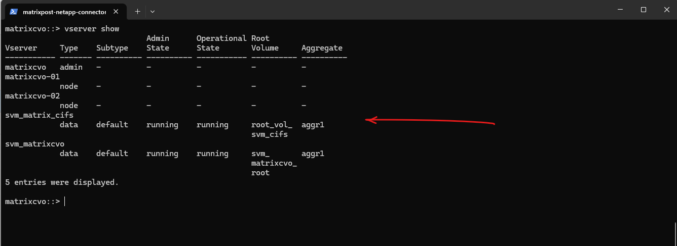
The
vserver showcommand provides a short overview of the SVM, whilevserver show -instancedisplays the complete configuration including enabled protocols, security settings, and operational details. The instance view is especially useful for validation and troubleshooting.
matrixcvo::> vserver show -vserver svm_matrixcvo -fields allowed-protocols
matrixcvo::> vserver show -vserver svm_matrixcvo -instance
Create a Management LIF for the SVM
After creating the SVM, its also best practices to create a Management LIF (Logical Interface). This LIF is used for administrative access to the SVM, including management via CLI, System Manager, and protocol configuration.
In ONTAP, an SVM does not technically require a dedicated management LIF in order to function , CIFS and other protocols can run entirely on data LIFs, and many on-prem environments work this way without issues.
However, separating management and data LIFs remains a best practice, especially in cloud deployments like Azure CVO, because it isolates administrative traffic, improves manageability, and aligns with network design patterns.
By default for the preconfigured SVM by the NetApp console (in my case
svm_matrixcvo) a SVM management LIF/IP and dedicated data LIFs were configured.Source: https://docs.netapp.com/us-en/storage-management-cloud-volumes-ontap/reference-networking-azure.html
It must be placed in the correct Azure subnet and associated with the proper network settings to ensure reliable connectivity, especially in HA deployments where networking and routing need to be precise from the start.
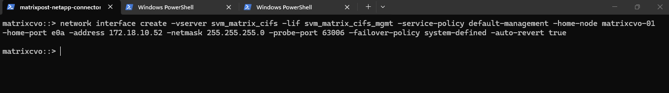
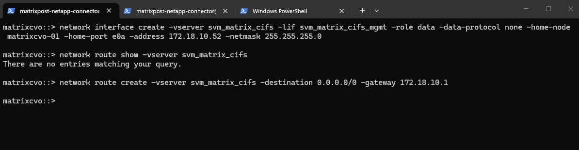
The Management LIF is created using the following command, which assigns a dedicated IP address (in my case I will use here 172.18.10.52) to the SVM, binds it to the correct node and port, and configures it without a data protocol since it is used purely for management purposes:
In Azure CVO, the probe port is the signal that tells the Azure Load Balancer which node is currently active, while the failover policy is the permission for that IP to move to the partner node during an outage. Together, they bridge the gap between ONTAP’s storage failover and Azure’s network routing to ensure continuous data access.
The
system-definedfailover policy acts as an intelligent “auto-pilot” that dynamically assigns the best failover targets based on the LIF’s service policy and network configuration. For data and management LIFs, it typically defaults to abroadcast-domain-widescope, ensuring the IP can automatically migrate to any healthy port on the partner node within the same network segment.While we can also use
sfo-partner-onlyfor the failover policy to ensure a LIF stays strictly within its 2-node HA pair, the modernsystem-definedpolicy is preferred because it offers greater flexibility by automatically adapting to your broadcast domain’s specific topology.
matrixcvo::> network interface create -vserver svm_matrix_cifs -lif svm_matrix_cifs_mgmt -service-policy default-management -home-node matrixcvo-01 -home-port e0a -address 172.18.10.52 -netmask 255.255.255.0 -probe-port 63006 -failover-policy system-defined -auto-revert true
The
default-managementservice policy in the command above replaces the legacy “management” role by explicitly authorizing the LIF to handle administrative traffic such as SSH, HTTPS, and SNMP.For a data LIF (NFS or CIFS), you would use
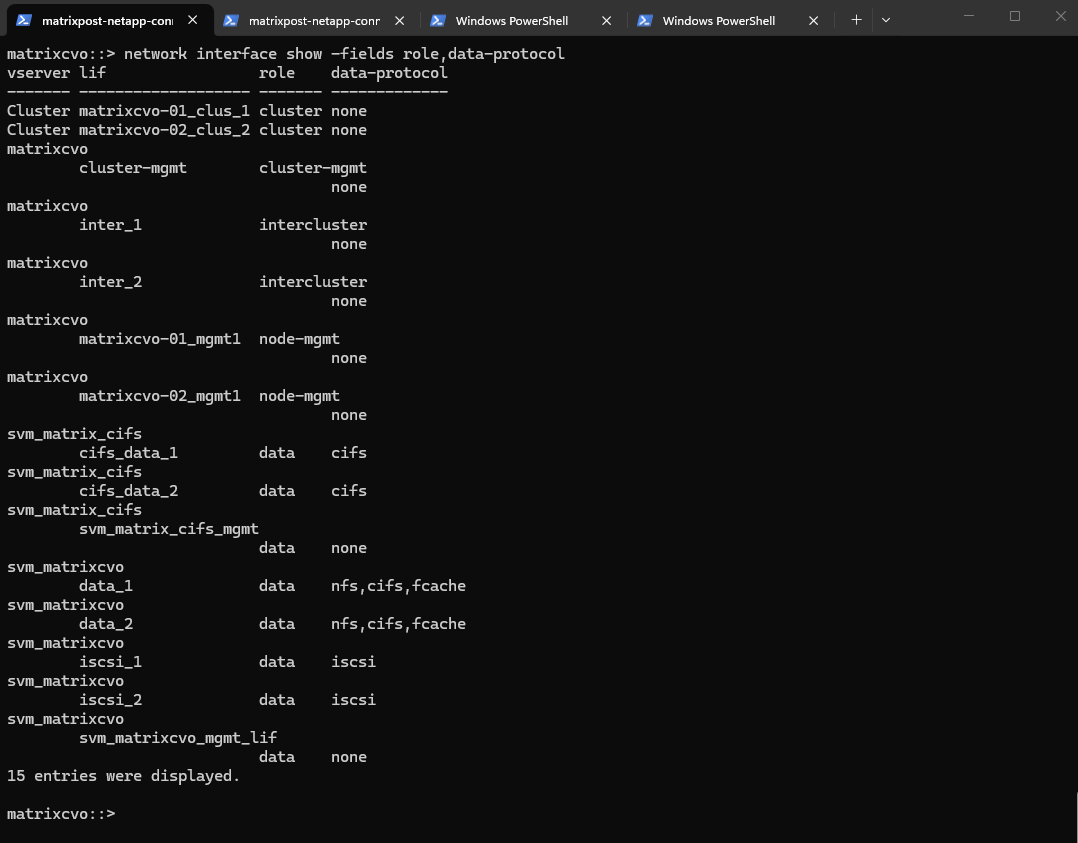
-service-policy default-data-filesinstead.By using this policy, ONTAP ensures that management tasks are isolated from data services, preventing the interface from responding to file-level protocols like NFS or SMB. This modernization provides a more granular security posture.
matrixcvo::> network interface show -fields role,data-protocol
Before continuing, it’s important to verify whether a default route already exists for the new SVM, if missing create it.
If no default route is present, one must be created so the SVM can reach external services such as DNS servers and the Active Directory domain controllers, which is required for a successful CIFS/SMB configuration.
In Azure, the first usable IP address of every subnet is always reserved as the default gateway, implemented by Azure’s software-defined router (SDN). This gateway is not a VM, not visible, and not configurable, it’s Azure’s internal routing fabric.
Reserved by Azure:
172.18.10.0→ network address,172.18.10.1→ Azure default gateway,172.18.10.2–3→ Azure internal use, Usable for VMs: starting at172.18.10.4
matrixcvo::> network route show -vserver svm_matrix_cifs
matrixcvo::> network route create -vserver svm_matrix_cifs -destination 0.0.0.0/0 -gateway 172.18.10.1
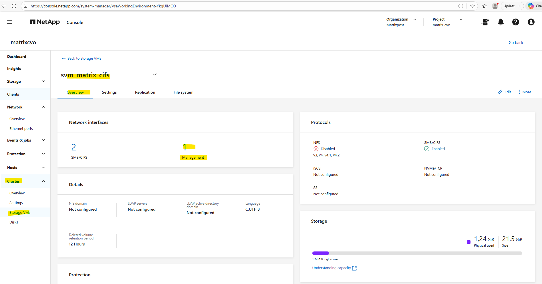
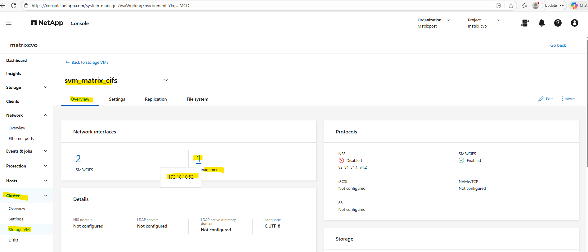
When creating a dedicated management LIF for an SVM, it is automatically reflected in ONTAP System Manager under Cluster → Storage VMs → Overview → Network Interfaces.
There, System Manager clearly separates the data protocol LIFs (SMB/CIFS or NFS) from the management LIFs, displaying both the number of interfaces and their respective IP addresses as shown below.
Azure Internal Load Balancer Configuration for the Management LIF
After creating the management LIF on the SVM, it is not reachable automatically, not even from within the same subnet. This also true for LIFs in general created for Cloud Volume ONTAP nodes in Azure.
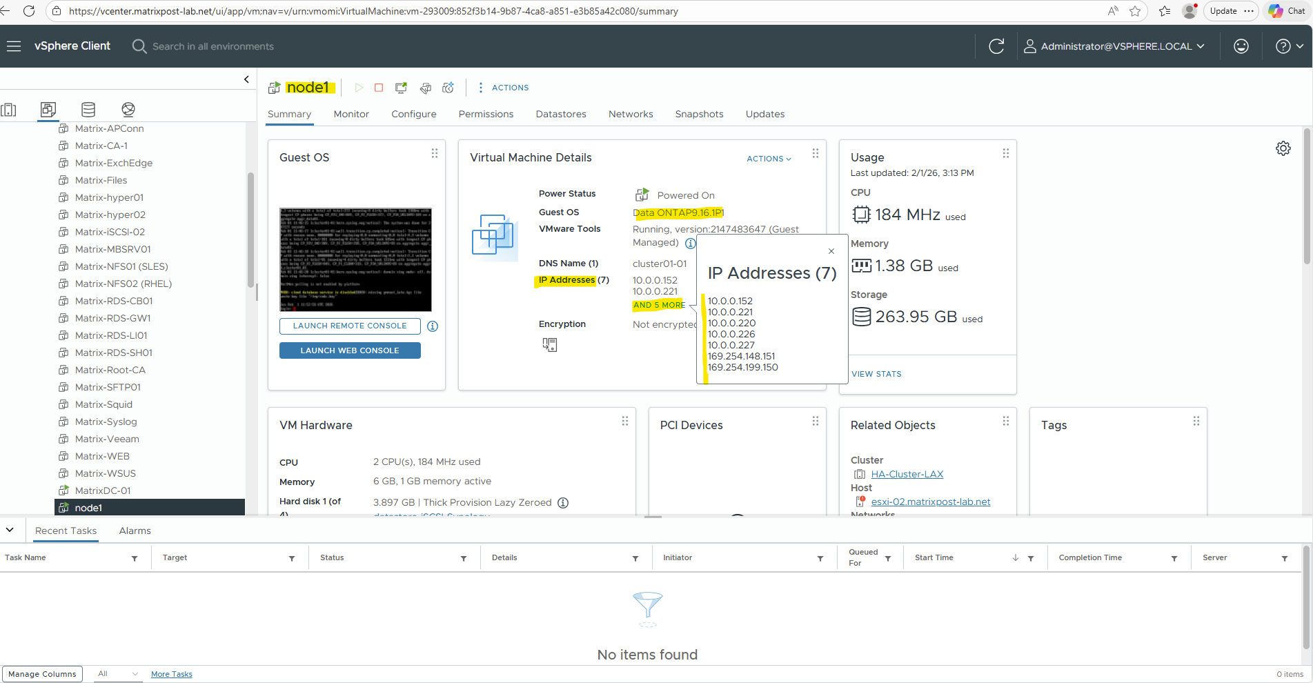
Unlike on physical ONTAP systems or in a vSphere-based lab environment (where a newly created LIF immediately appears as an IP address on the virtual NIC), in Azure it behaves differently.
In Azure, the IP address of the LIF is not automatically assigned to the virtual network interface of the VM (node), which means the LIF is unreachable until the Azure Internal Load Balancer is configured accordingly.
While the NetApp console (formerly BlueXP) allocates IP addresses to the Azure NICs during deployment, the mapping of LIFs to these IPs is managed by ONTAP software, not by Azure networking API calls.
This is why, after creating a LIF, you must manually update the Azure Internal Load Balancer (ILB) by adding:
- a frontend IP configuration
- a health probe
- a load-balancing rule
Only after these components are in place will the LIF become reachable, even from within the same virtual network and subnet.
In a vSphere-based ONTAP deployment, this behavior is more transparent, as the LIF IP becomes visible directly on the VM’s network interface. In Azure, however, this mapping must be handled explicitly through the ILB.
The reason our vSphere Lab and physical NetApps “expose” LIFs directly, while Azure CVO does not, comes down to Layer 2 vs. Layer 3 networking control.
On-premises and vSphere environments operate on Layer 2, allowing ONTAP to dynamically “claim” any IP via ARP broadcasts that the underlying network simply trusts and passes through.
In contrast, Azure uses a Layer 3 Software Defined Network that ignores ARP and strictly drops traffic unless the IP is explicitly whitelisted and routed via the Azure fabric API. Consequently, CVO uses floating IPs and Route Tables to move traffic between nodes rather than relying on the vNIC to “expose” every individual address.
Below we will see the first VM’s (nodes) virtual network interface and its primary private IP address with 172.18.10.16.
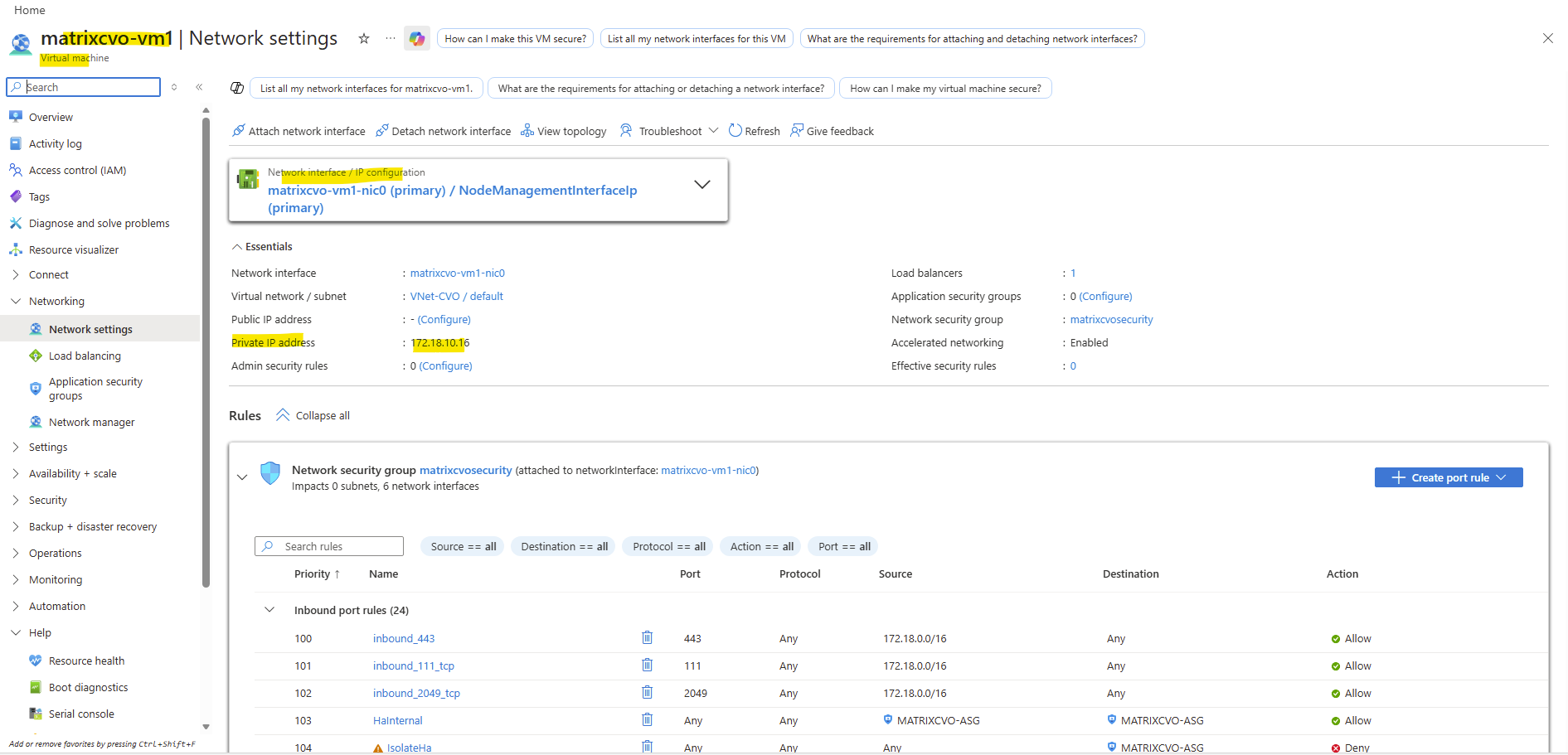
When clicking above on the network interface, we will see all directly assigned private or public IP addresses.
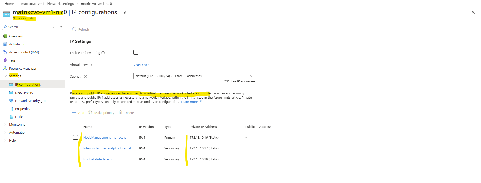
Our previously created Management LIF (command below) with the IP address 172.18.10.52 is not assigned here.
matrixcvo::> network interface create -vserver svm_matrix_cifs -lif svm_matrix_cifs_mgmt -service-policy default-management -home-node matrixcvo-01 -home-port e0a -address 172.18.10.52 -netmask 255.255.255.0 -probe-port 63006 -failover-policy system-defined -auto-revert true
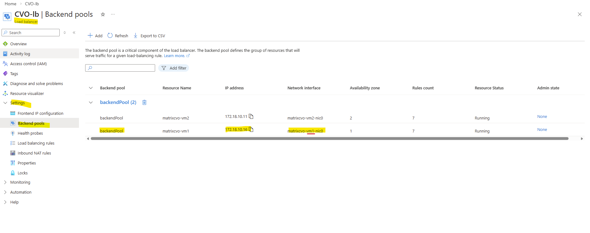
Therefore the node management interface IP with 172.18.10.16 (shown above on the network interface of the first node) is assigned to the backend pool of the internal load balancer (ILB) in Azure as shown below.
Behind the scenes, the Azure Internal Load Balancer backend pool contains the node management interfaces of both CVO nodes.
All frontend IP configurations that you create for individual LIFs are ultimately routed through this backend pool.
Therefore, ONTAP LIFs are not reachable until they are mapped through an Azure Internal Load Balancer. Azure itself has no awareness of it until the corresponding ILB configuration is created.
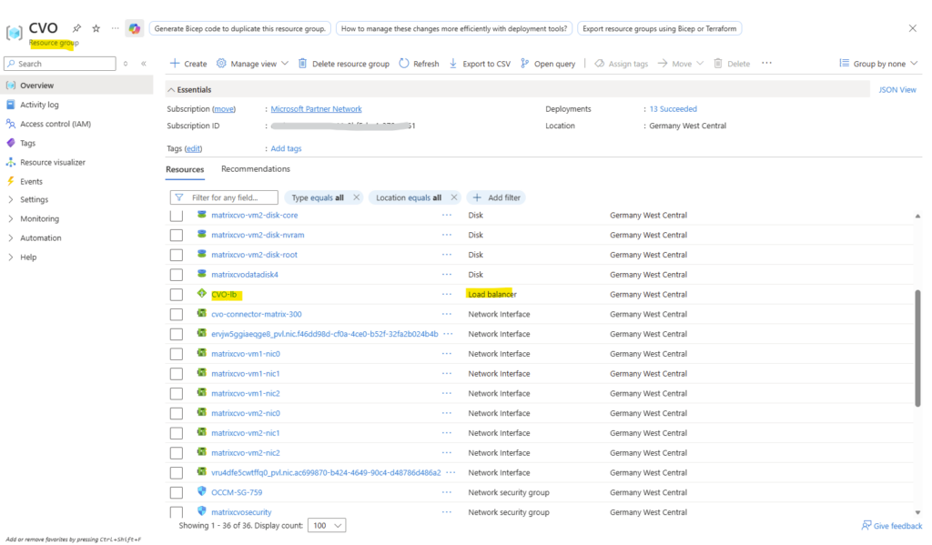
When deploying Cloud Volumes ONTAP through the NetApp Console, the Azure Internal Load Balancer (ILB) is created automatically as part of the deployment and shown below in the dedicated resource group for CVO.
However, this initial configuration only covers the default system interfaces.
For every newly created LIF, the ILB must be manually extended with the corresponding frontend IP configuration, health probe, and load-balancing rule to make the LIF reachable as mentioned.
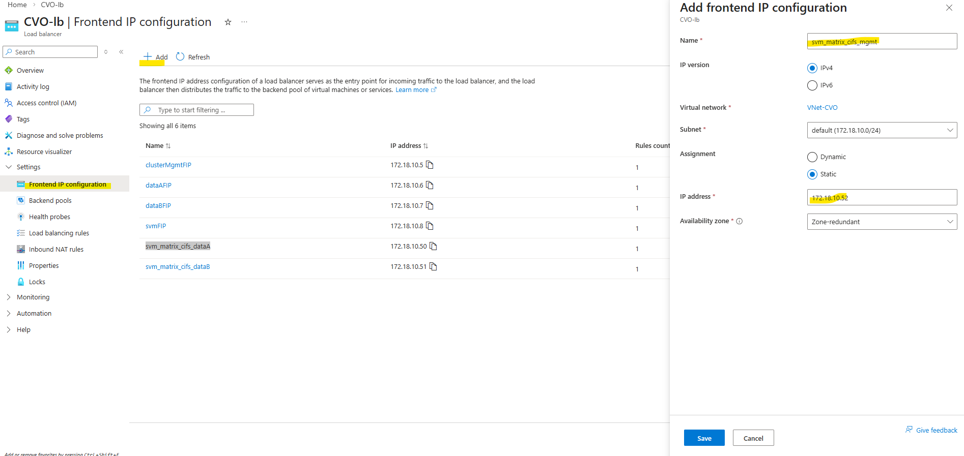
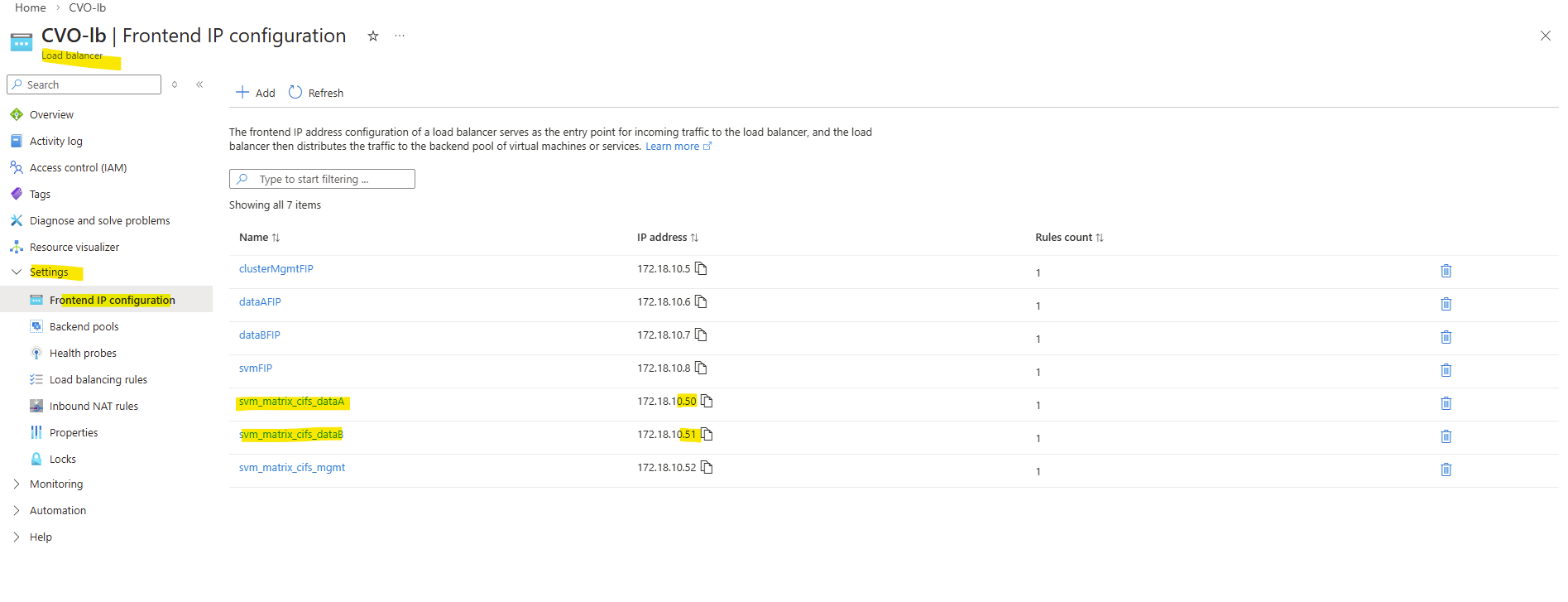
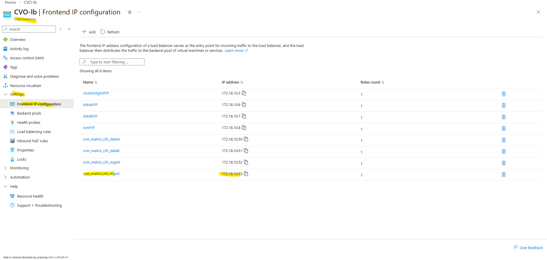
So first I will add the newly created management LIF and its assigned IP address 172.18.10.52 as new frontend IP configuration on the ILB within Settings -> Frontend IP configration, click on + Add.
Enter a name for the new frontend IP configuration, the IP version, the virtual network and subnet the IP is attached to, for the assignment select Static.
Finally enter the IP address of our new management LIF and for the availability zone leave Zone-redundant.
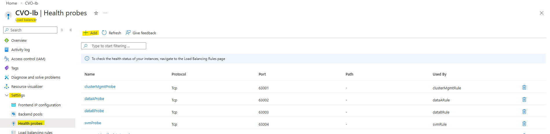
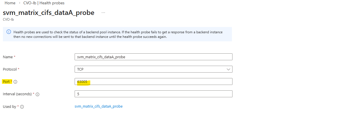
Next we need to create a new health probe for our new frontend IP configuration.
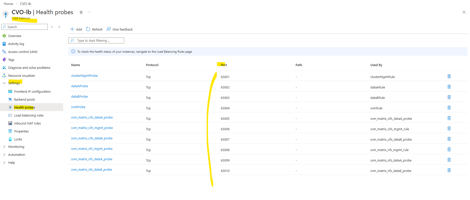
On the ILB within Settings -> Health Probes, click on + Add.
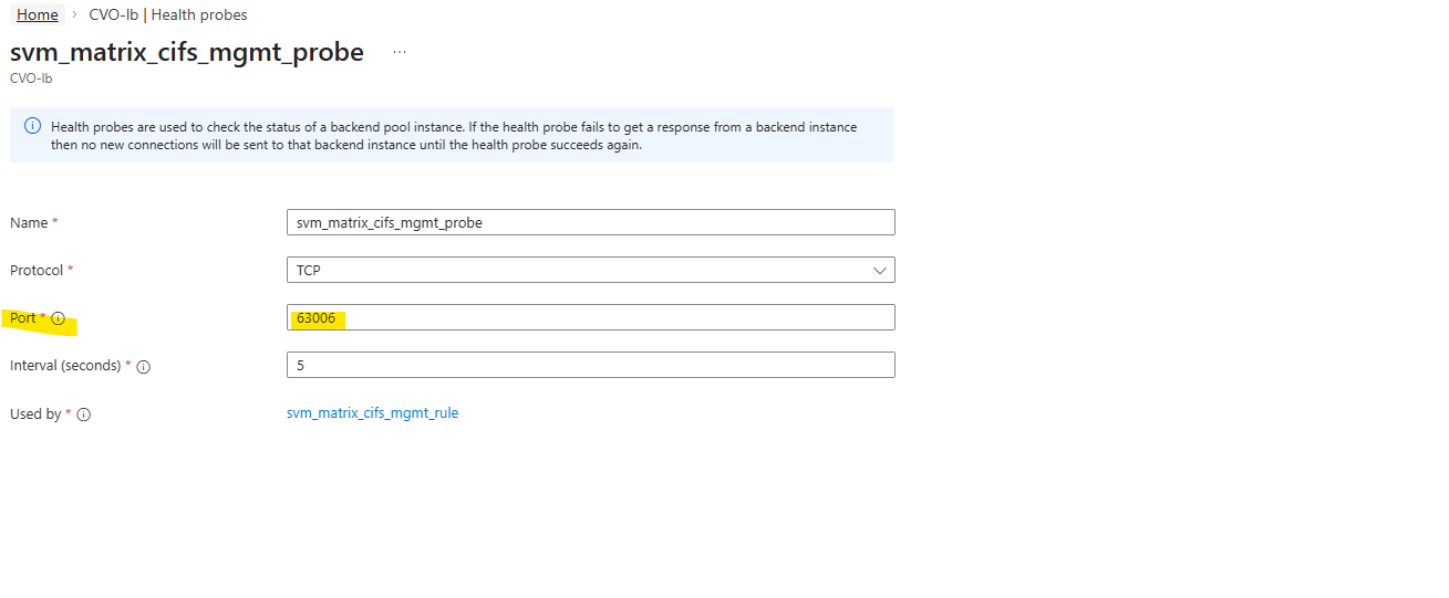
In Azure CVO, every single LIF that needs to be reachable through the Load Balancer must have its own unique port (usually between 63001 and 65000).
We cannot share ports because the Load Balancer uses that specific port number as a “ID” to track that specific IP. If two IPs used the same port, the Load Balancer wouldn’t know which one was actually responding.
So every health probe in Azure must use a unique port.
TCP 63006 is the NetApp CVO HA health-probe port.
This is how Azure knows which node owns the floating IP.
It is pure HA signaling.The probe checks whether the active CVO node is reachable on the expected port.
It is required so Azure knows which backend node is currently serving the LIF.
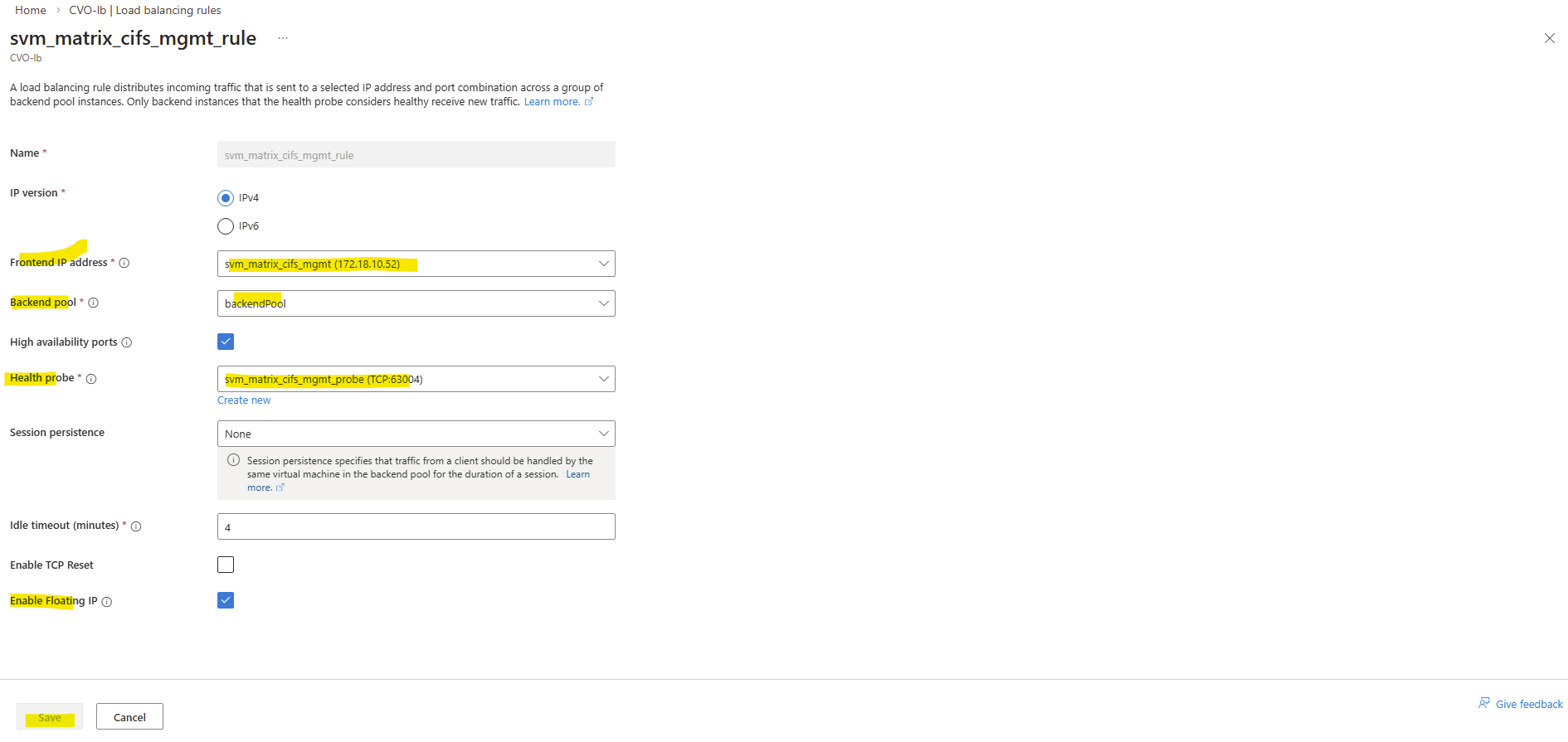
And finally we need to create new load balancing rule.
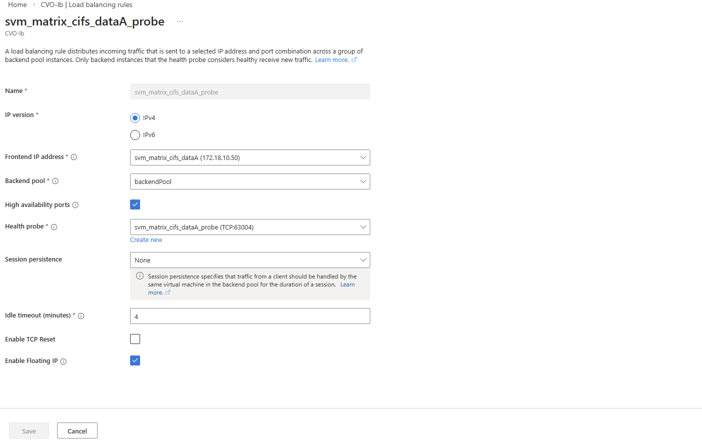
On the ILB within Settings -> Load Balancing rules, click on + Add.
Select the IP version, our previously created frontend IP address, our backend pool, check High availability ports, select our previously created health probe, for session persistance select None, Idle timeout leave 4 minutes and finally check Enable Floating IP.
High Availability Ports must be enabled so Azure forwards all traffic to the active CVO node. This is required because ONTAP uses multiple ports and the LIF is not bound to a single service port.
ONTAP handles session management itself, and persistence at the load balancer level is not required.
Enable Floating IP is required for ONTAP because the service IP (LIF) is not bound directly to the VM’s NIC and must be preserved end-to-end for correct routing and failover behavior.
Each Azure Health Probe must use the exact same port we assigned previously to the LIF during creation (e.g., 63006). This alignment is what allows the Azure Load Balancer to “see” the LIF and route traffic to the correct active node.
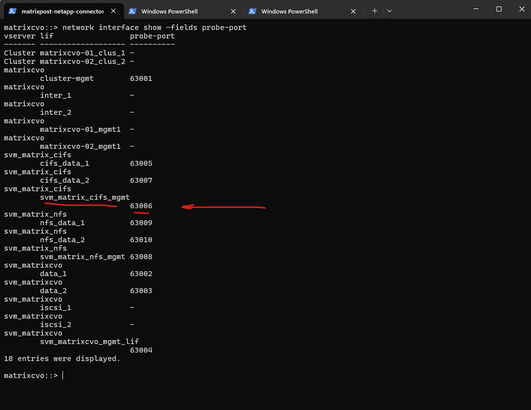
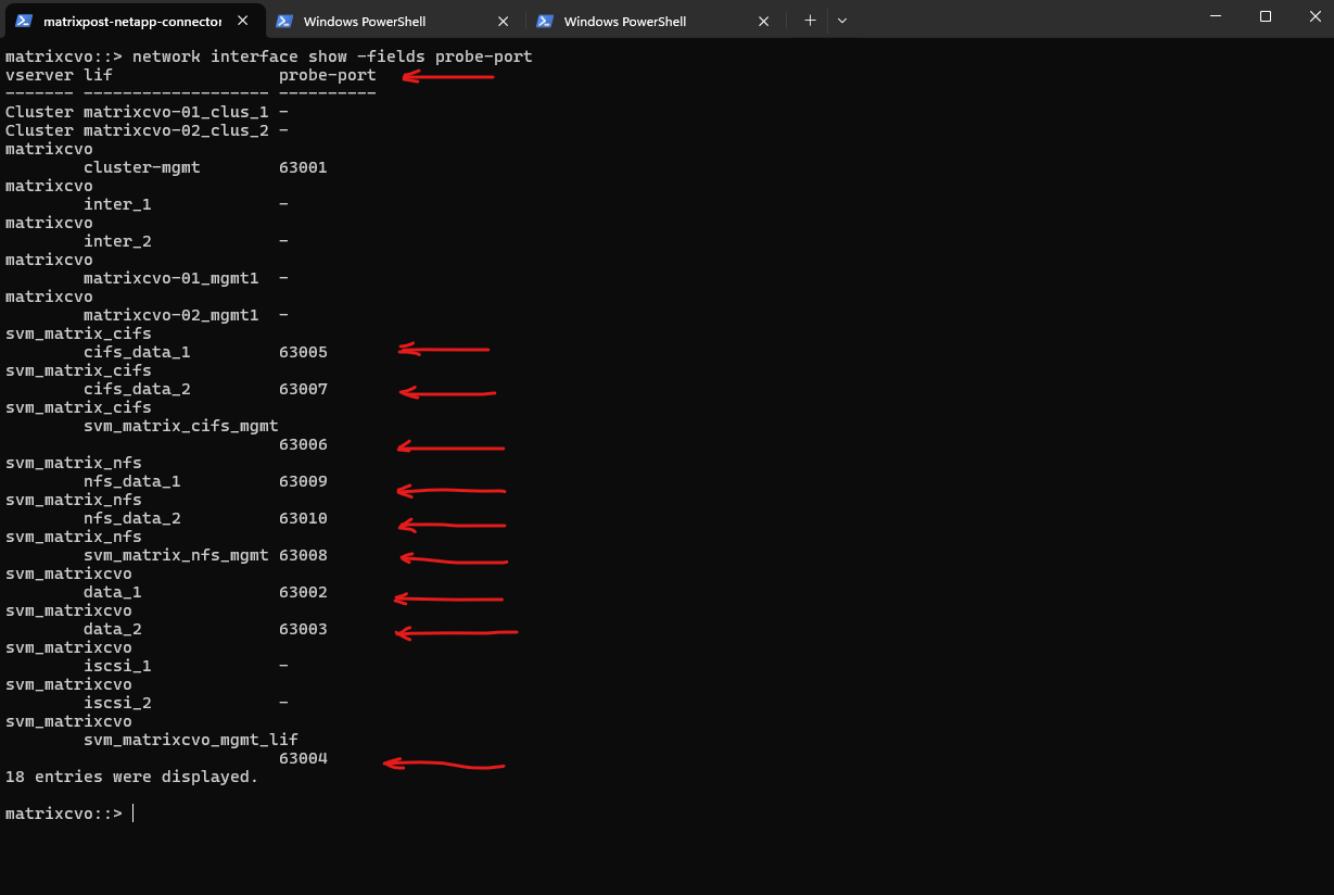
We can verify the probe-port we set in ONTAP by running the following command.
So inside ONTAP we aligned the configuration by assigning the exact same probe port (63006) to the CIFS SVM management LIF that Azure uses for its health probe.
This tight coupling ensures that the Azure Load Balancer can accurately detect which node is actively serving the LIF.
In short: Azure probes the port, ONTAP listens on it and high availability finally works as designed.
matrixcvo::> network interface show -fields probe-port
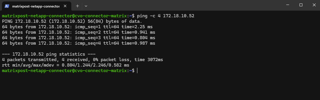
Why we can now already ping 172.18.10.52 from e.g. the connector VM below which runs in the same subnet.
- The SVM management IP is bound to a real NetApp HA-managed interface
- Azure now considers the backend healthy
- Traffic is forwarded correctly
- ICMP reaches ONTAP
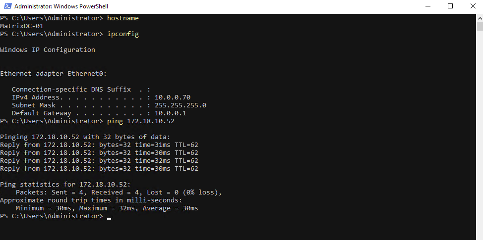
I can also reach the management IP from my on-prem DC.
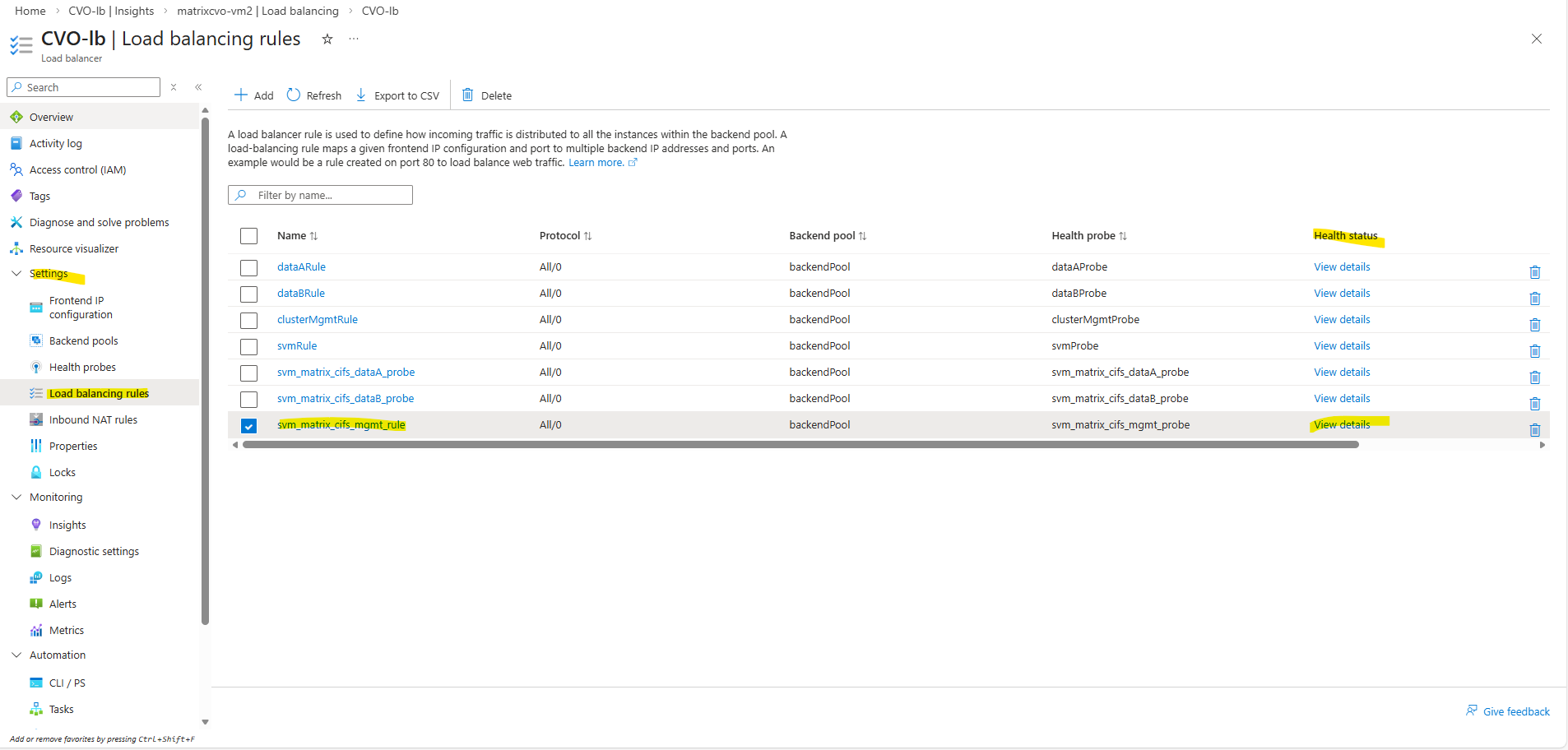
We can also check the health status of the load-balancing rule directly in Azure by navigating to ILB → Settings → Load balancing rules and clicking the Health status column of the rule you want to inspect, then selecting View details.
When a SVM is active on one CVO node, ONTAP binds the management LIF to that node only, causing Azure ILB health probes to succeed on the active node while intentionally timing out on the passive node.
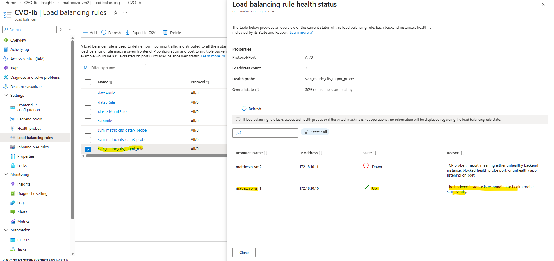
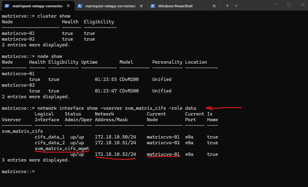
We also verify the currently active node directly from the ONTAP CLI. By checking the CIFS SVM data and management LIF placement, ONTAP shows which CVO node is actively serving client traffic at that moment.
matrixcvo::> cluster show
matrixcvo::> node show
matrixcvo::> network interface show -vserver svm_matrix_cifs -role data
Create the Data LIFs for the new SVM
Creating an SVM alone is not sufficient to provide data access. Each SVM requires at least one data LIF, which represents the network endpoint used by clients to access storage services such as NFS or SMB. The LIF defines the IP address, subnet, and network path used by the SVM.
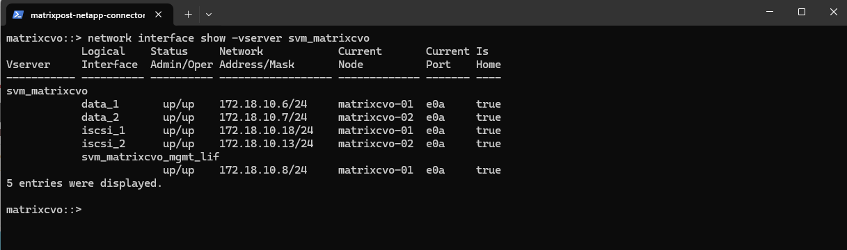
Before creating a new data LIF, it is useful to check the existing LIF configuration, below of the preconfigured SVM (
svm_matrixcvo) to identify the correct network, port, and addressing scheme that should be reused for the new SVM.
So first, check which port is used by existing data LIFs:
In most CVO deployments this will be
e0a.In an ONTAP HA configuration, each SVM should have at least two data LIFs, one hosted on each node. This ensures high availability, as LIFs automatically fail over to the partner node in case of a node failure. Clients continue accessing data using the same IP addresses, providing seamless failover without manual intervention.
Although ONTAP can fail over data LIFs between nodes, this mechanism is intended for fault tolerance, not normal operation. Best practice is to configure at least one data LIF per node so that each node actively serves client traffic. This ensures optimal performance, predictable failover behavior, and full utilization of the HA architecture.
From a pure availability standpoint, a single data LIF is sufficient, as ONTAP will fail it over to the partner node in case of a node failure. However, using one data LIF per node is considered best practice because it enables load distribution, improves performance, and fully utilizes the HA architecture.
matrixcvo::> network interface show -vserver svm_matrixcvo
Create a new data LIF for the SVM using a free IP address in the same subnet.
We can first check which IP addresses are already in use by a specific subnet in our connected subscription by running:
PS> az login

$SUBNET_ID= az network vnet subnet show -g <Ressource Group> --vnet-name <VNet Name> -n default --query id -o tsv

PS> $SUBNET_ID= az network vnet subnet show -g cvo --vnet-name VNet-CVO -n default --query id -o tsv

PS> az network nic list --query "[?ipConfigurations[?subnet.id=='$SUBNET_ID']].ipConfigurations[].privateIPAddress" -o table
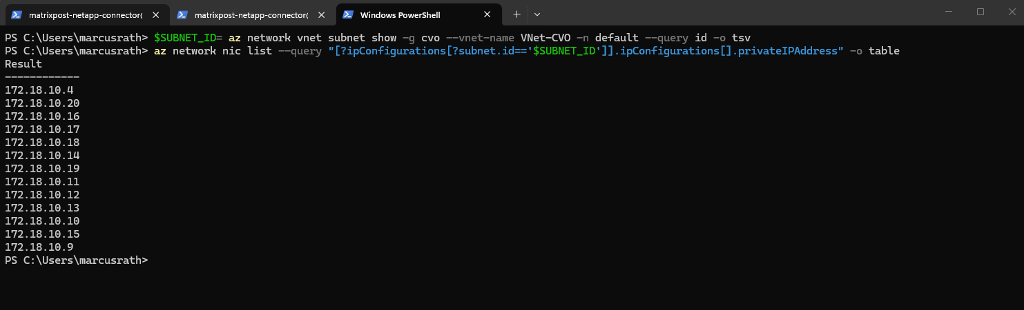
So for my new data LIFs I will use
172.18.10.50and172.18.10.51which both are not in use so far.Each data LIF requires its own unique probe port (e.g., 63005 and 63007) so the Azure Load Balancer can independently monitor and route traffic to each specific IP as previously for the management LIF.
Each probe port we assigned in ONTAP must now also be added as a Health Probe and a Load Balancing Rule in our Azure Internal Load Balancer (ILB).
By using
-service-policy default-data-files, we explicitly define the LIF’s allowed traffic (NFS/SMB) using the modern ONTAP networking stack rather than a legacy role. Combined with-failover-policy system-defined, the system automatically calculates the most resilient failover path within the broadcast domain, ensuring the LIF stays reachable during an Azure HA event.
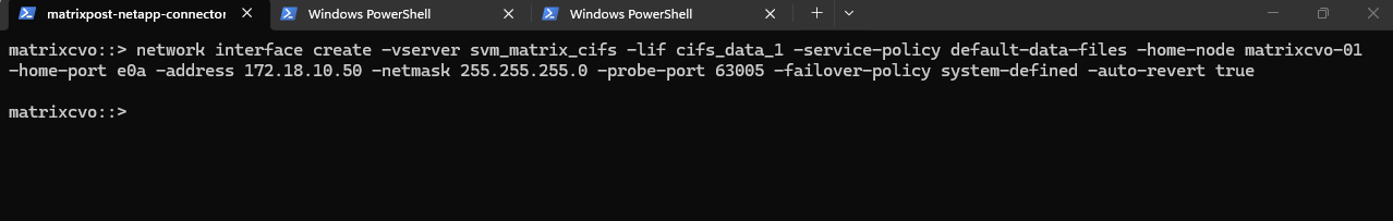
matrixcvo::> network interface create -vserver svm_matrix_cifs -lif cifs_data_1 -service-policy default-data-files -home-node matrixcvo-01 -home-port e0a -address 172.18.10.50 -netmask 255.255.255.0 -probe-port 63005 -failover-policy system-defined -auto-revert true
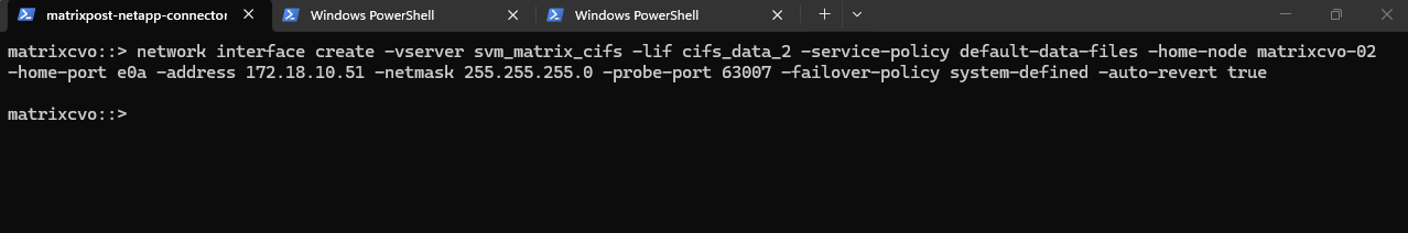
In HA setups, it is recommended to create one data LIF per node.
We should create two LIFs, one per node, with different names and IPs.
matrixcvo::> network interface create -vserver svm_matrix_cifs -lif cifs_data_2 -service-policy default-data-files -home-node matrixcvo-02 -home-port e0a -address 172.18.10.51 -netmask 255.255.255.0 -probe-port 63007 -failover-policy system-defined -auto-revert true
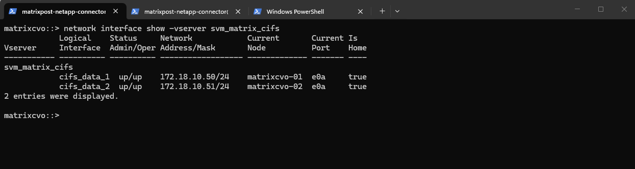
After creating the data LIFs, the SVM now has one active data interface per node. This setup follows NetApp best practices for high availability.
matrixcvo::> network interface show -vserver svm_matrix_cifs
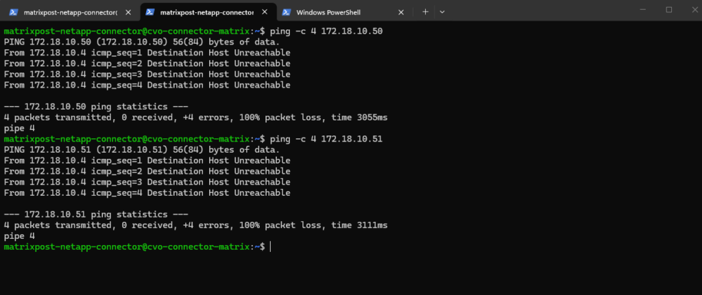
So far the new data LIF will remain unreachable until its IP address is added to the load balancer configuration, the same as previously for our new management LIF and IP address including the port-probes.
Here tested directly from the connector VM which runs in the same subnet.
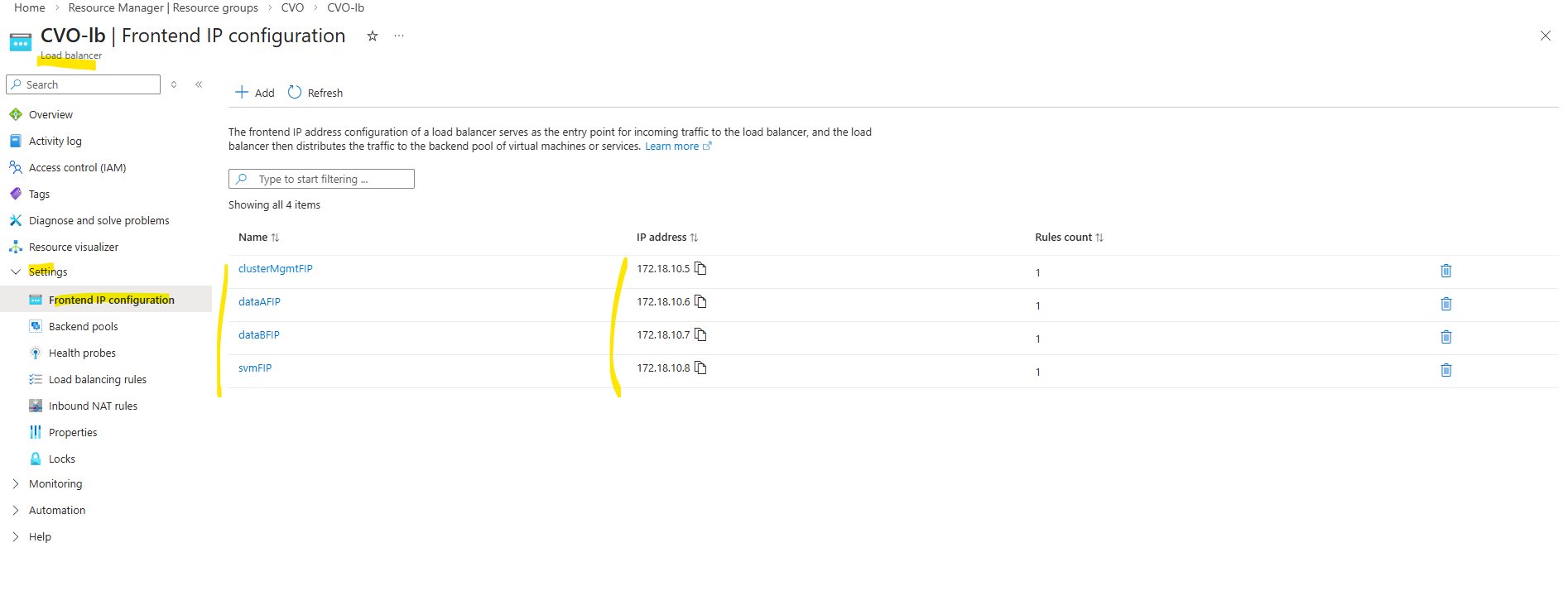
Below we will see the default frontend IP configuration on the ILB directly after deploying CVO by using the NetApp console and before we added previously our new management LIF.
- Cluster management IP → 172.18.10.5
Used for ONTAP cluster management. Accessed via: ONTAP CLI and System Manager. Not used for data traffic - dataAFIP → 172.18.10.6
Data LIF for node A. Used for NFS / SMB / iSCSI (depending on config). Client Access, Automatically failed over by the load balancer - dataBFIP → 172.18.10.7
Data LIF for node B. Used for NFS / SMB / iSCSI (depending on config). Client Access, Automatically failed over by the load balancer - svmFIP → 172.18.10.8
SVM management LIF. The management IP forsvm_matrixcvo:
Used for: SVM-scoped administration, CIFS/NFS configuration, Some API calls
This is not a data LIF, but an SVM-level endpoint.
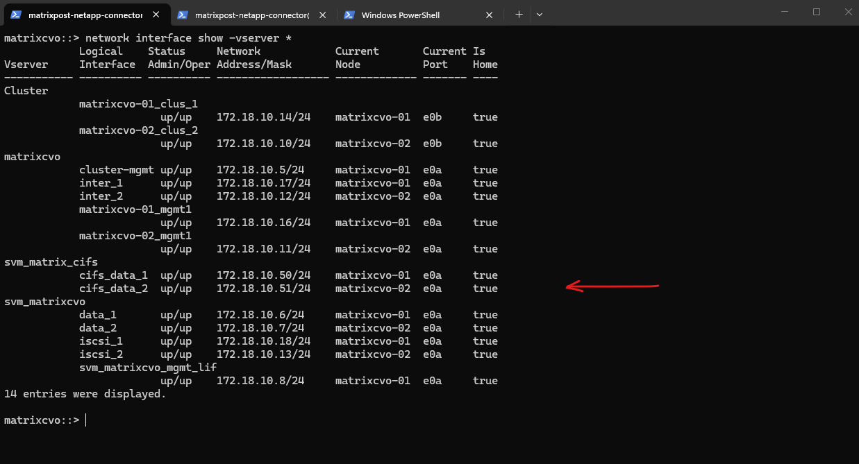
So we also need to add our both new data LIF IP addresses to the ILB configuration.
matrixcvo::> network interface show -vserver *
After creating the data LIFs in ONTAP, the next step is to add the corresponding IP addresses to the Azure internal load balancer.
The configuration of the health probe for both data LIFs is the same as previously for the management LIF.
Assign the same port for the health probe as we used when creating the LIF and using the -probe-port flag.
Also the configuration for the load balancing rules for each data LIF.
Finally much later when I also added nfs management and data LIFs, all probes as mentioned needs to use different ports which aligns with the ONTAP port-probe configuration for these LIFs, otherwise they will not listen in ONTAP on this TCP port and the health probes will fail.
matrixcvo::> network interface show -fields probe-port
About creating a new storage virtual machine (SVM) in ONTAP you can also read my following post.
Create a Volume
After creating and configuring a SVM, the next step is to create a new volume that will be used to store and present data to clients.
The volume must be created on the correct SVM and mounted into its namespace so it can later be shared via SMB and/or NFS
A volume in NetApp ONTAP is a logical, mountable unit of storage that resides inside an aggregate, is served by a Storage Virtual Machine (SVM), and is accessible to clients via NFS, SMB, iSCSI, or FC.
ONTAP Cloud supports up to 500 FlexVol volumes per node. Since volumes are hosted on nodes rather than directly limited per SVM, an SVM can use all available volumes on its hosting node, subject to overall system limits and sizing considerations.
Below we will create a 5 GB data volume called vol_data01 on aggr1.
matrixcvo::> volume create -vserver svm_matrix_cifs -volume vol_cifs_data01 -aggregate aggr1 -size 10GB
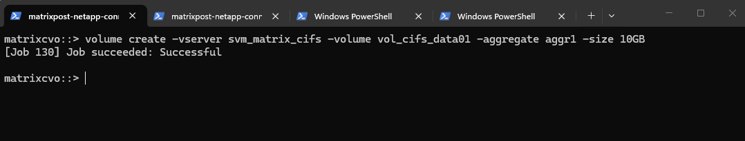
We can check the creation by running.
matrixcvo::> volume show -vserver svm_matrix_cifs
matrixcvo::> volume show -volume vol_cifs_data01 -instance
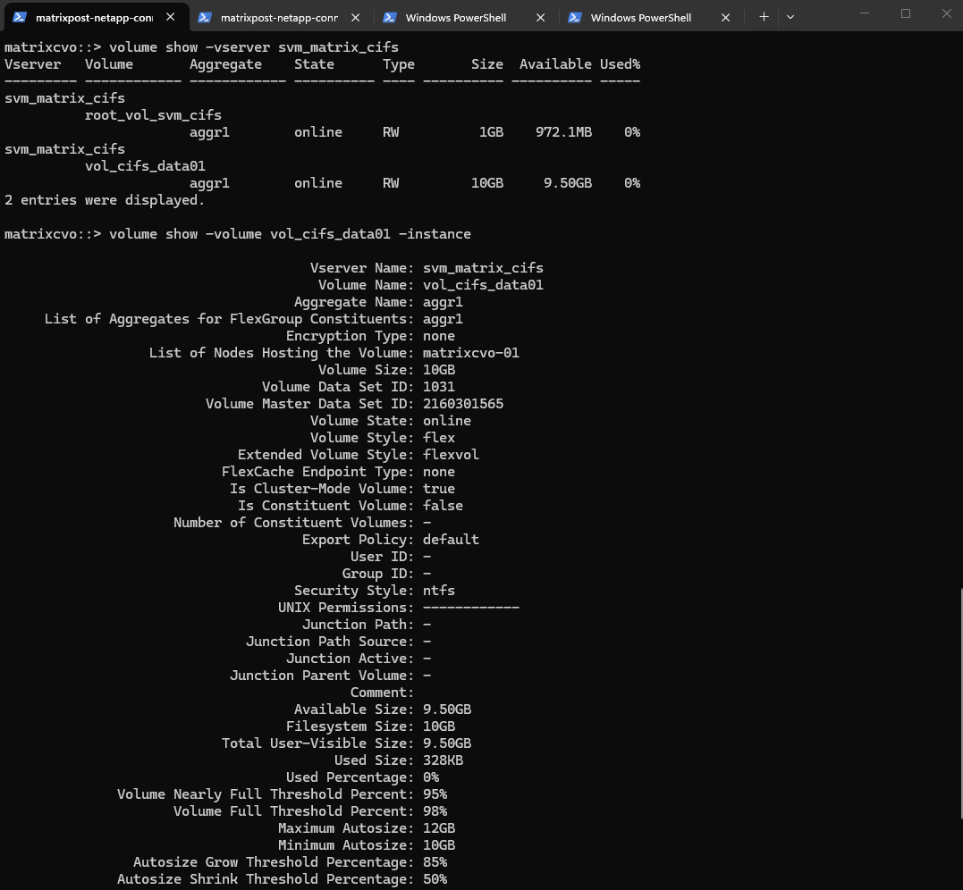
Or by using the ONTAP System Manager and here within Storage -> Volumes.
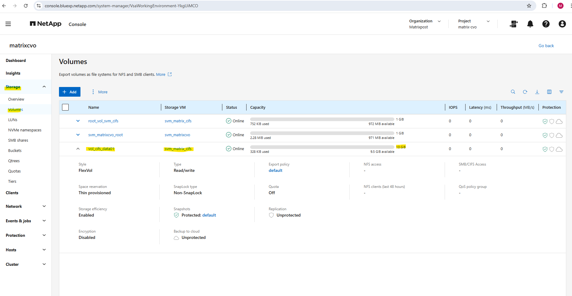
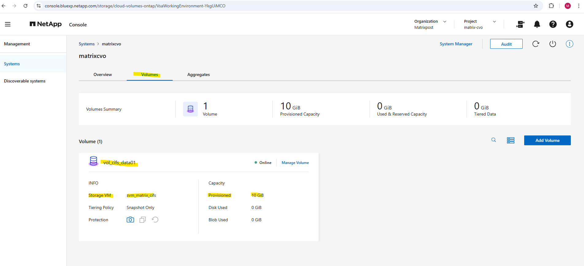
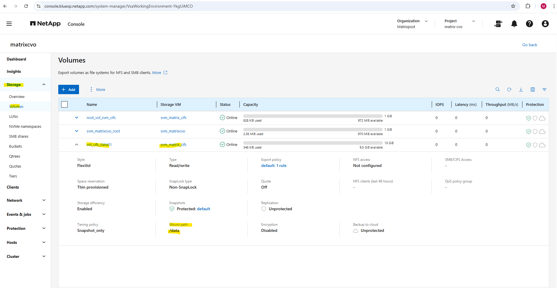
And also by using the NetApp console under Storage -> Management -> Systems, here select our system and click on the right bar on Enter System.
Within the Volumes tab we will find our newly created volume named vol_cifs_data01.
The WAFL Foundation: One File System, Many Faces
When creating a volume, you don’t need to worry about choosing an underlying file system (like NTFS or XFS) for the storage itself; whether the volume is used for block (LUNs), Windows (SMB), or Linux (NFS) files, NetApp always uses its native WAFL (Write Anywhere File Layout).
Your primary focus is simply selecting the correct Security Style for the volume, which dictates how WAFL handles permissions.
Unlike a local disk where a Windows OS must format a partition as NTFS or a Linux OS must format it as Ext4/XFS, the NetApp SVM abstracts the storage entirely.
On a local server, the OS owns the file system structure directly on the metal; on NetApp, the ONTAP operating system owns the WAFL layer and merely “presents” a compatible interface to the clients, allowing it to store Windows ACLs and Linux permissions side-by-side in the same physical blocks.
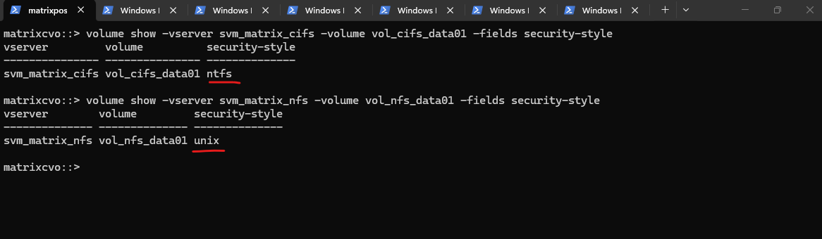
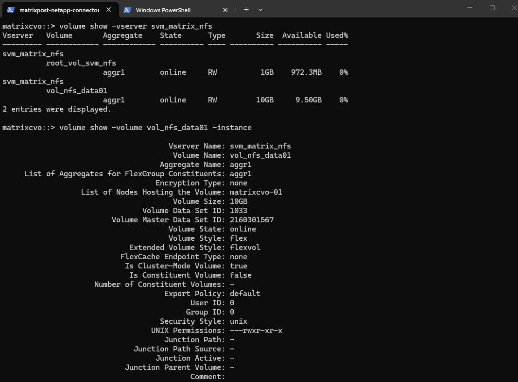
The output above demonstrates how ONTAP uses the security style to define the “personality” of the underlying WAFL volume.
In the first example,
vol_cifs_data01is set to ntfs, telling WAFL to store and honor Windows-style ACLs, whereasvol_nfs_data01is set to unix, directing WAFL to use standard UID/GID mode bits for permissions.Even though both volumes live on the same storage system and use the same physical file layout, these settings ensure each volume behaves exactly like a native local file system for its respective Windows or Linux clients.
# volume used for cifs/smb shares
matrixcvo::> volume show -vserver svm_matrix_cifs -volume vol_cifs_data01 -fields security-style

# volume used for nfs shares (exports)
matrixcvo::> volume show -vserver svm_matrix_nfs -volume vol_nfs_data01 -fields security-style
When you skip the -security-style flag during a volume create command, ONTAP intelligently defaults the new volume to match the Root Volume of the hosting SVM.
This means that if your SVM was provisioned for Windows/CIFS, every new volume automatically inherits the NTFS style, ensuring the WAFL layer is pre-configured to handle Windows SIDs without any manual intervention.
This inheritance streamlines provisioning, as the system aligns the volume’s internal permission structure with the primary protocol used by that specific SVM.
# Overriding the SVM default during creation
matrixcvo::> volume create -vserver svm_matrix_cifs -volume vol_test -aggregate aggr1 -size 10GB -security-style unix
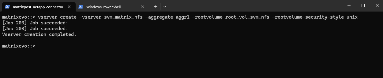
When you first execute the vserver create command, the -rootvolume-security-style parameter establishes the “DNA” for that entire Storage Virtual Machine. This setting ensures that any volume subsequently created within that SVM automatically inherits the correct WAFL metadata structure, whether ntfs or unix, aligning the storage with your primary protocol without further manual configuration.
matrixcvo::> vserver create -vserver svm_matrix_nfs -aggregate aggr1 -rootvolume root_vol_svm_nfs -rootvolume-security-style unix
ONTAP Volume Management: Automating Growth and Shrinkage (Autosize)
One of the most powerful features in ONTAP for “set it and forget it” storage management is Autosize.
Instead of waiting for an aggregate to fill up or manually resizing volumes when they hit 90%, you can configure volumes to grow (and shrink) automatically based on predefined thresholds.
All about you will find in my post here https://blog.matrixpost.net/cheat-sheet-netapp-ontap-commands-used-in-day-to-day-operations/#autosize.
Snapshot Reserve: How Much Space Do Snapshots Really Need?
When working with ONTAP volumes, it’s easy to focus on size, tiering, and performance, but Snapshot Reserve is just as important. It directly influences how much writable space your volume actually has and how Snapshot growth is handled. Let’s take a closer look at what happens behind the scenes and how to size it properly.
The Snapshot Reserve is a dedicated percentage of a volume’s total capacity set aside exclusively for storing point-in-time recovery copies. By isolating this space from the “Active File System,” ONTAP ensures that routine data changes don’t overwrite your backup history, preventing a sudden influx of new data from deleting your older recovery points.
While the default is typically set to 5%, finding the “sweet spot” for this reserve is critical to maximizing usable space without compromising your RPO (Recovery Point Objective).
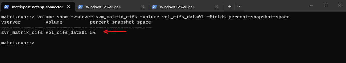
Use this command to see the percentage of space locked away for snapshots on a specific volume:
matrixcvo::> volume show -vserver svm_matrix_cifs -volume vol_cifs_data01 -fields percent-snapshot-space
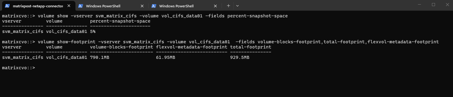
Run this to see the breakdown of what is actually taking up space:
volume-blocks-footprint: This is your actual data (the active file system).total-footprint: This is the sum of everything, your data, snapshots, and metadata.flexvol-metadata-footprint: The “overhead” ONTAP needs just to manage the volume.
matrixcvo::> volume show-footprint -vserver svm_matrix_cifs -volume vol_cifs_data01 -fields volume-blocks-footprint,total-footprint,flexvol-metadata-footprint
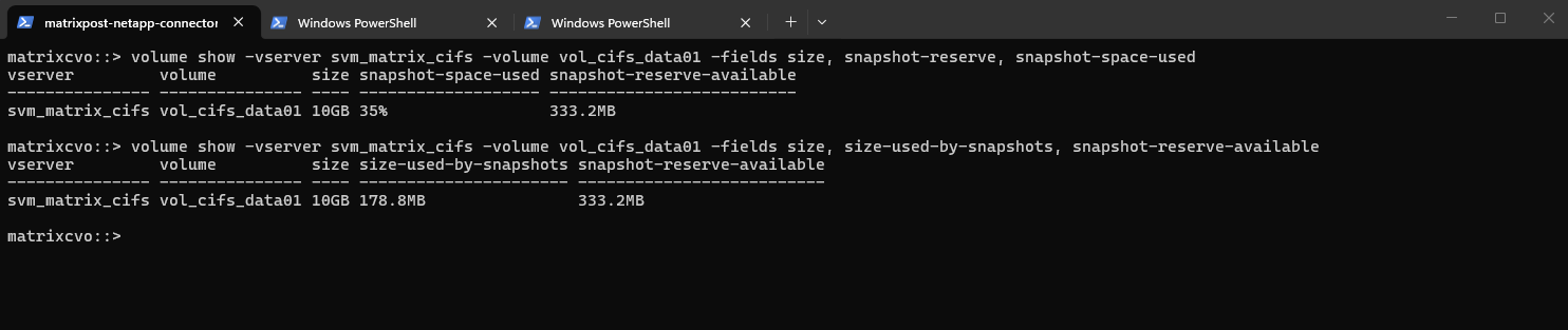
We can use the commands below to check how much space within the volume is currently consumed by Snapshot copies and how much of the reserved Snapshot space is still available.
Below our 10 GB volume has 178.8 MB used by Snapshots, which corresponds to 35% of the configured Snapshot reserve, leaving 333.2 MB still available. This helps you quickly determine whether Snapshot growth is approaching the reserve limit and whether adjustments might be required.
matrixcvo::> volume show -vserver svm_matrix_cifs -volume vol_cifs_data01 -fields size, snapshot-reserve, snapshot-space-used
matrixcvo::> volume show -vserver svm_matrix_cifs -volume vol_cifs_data01 -fields size, size-used-by-snapshots, snapshot-reserve-available
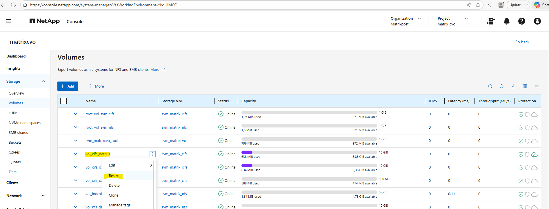
We can resize the Snapshot reserve by using either the ONTAP System Manager or the ONTAP CLI.
By using the ONTAP System Manager, within Storage -> Volumes, click on the three dots besides the desired volume you want to resize and select Resize as shown below.
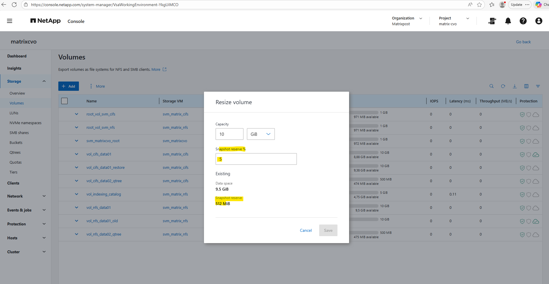
Our CLI output above was showing that 35% of the Snapshot reserve is used (178.8 MB) and that 333.2 MB are still available. If we add both together (178.8 MB + 333.2 MB), we get ~512 MB total Snapshot reserve.
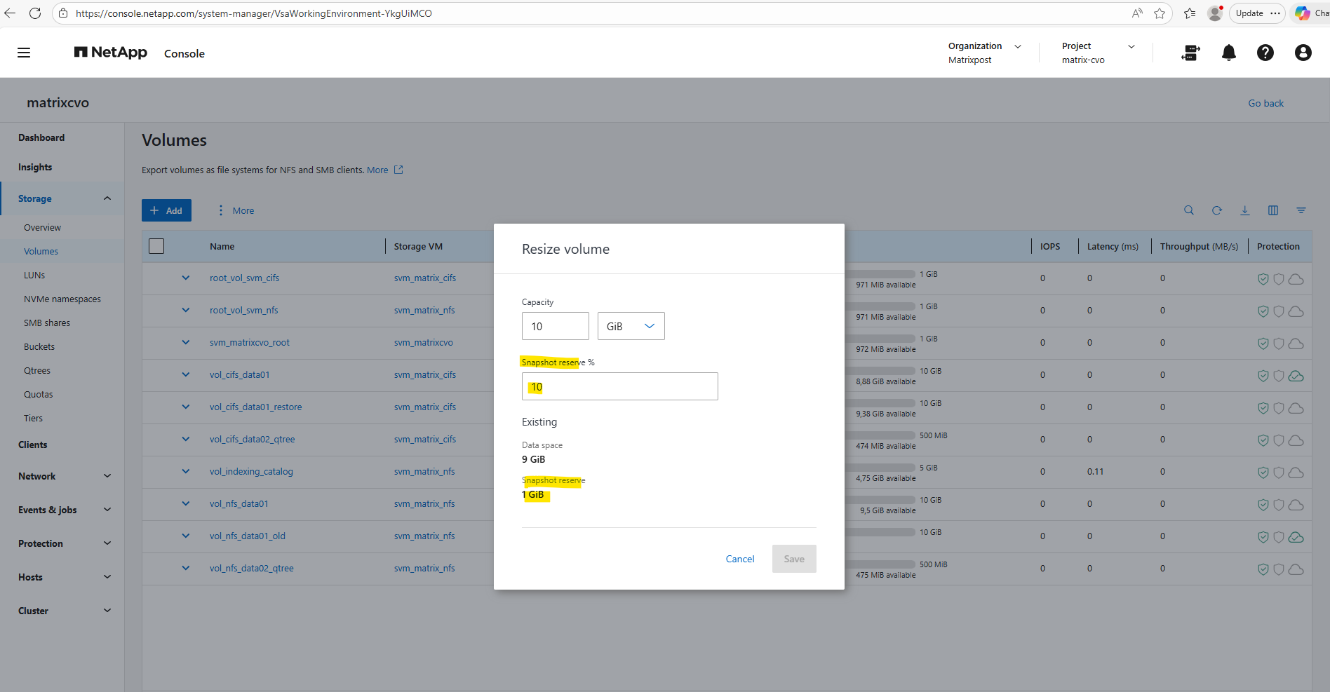
Adjust the Snapshot reserve %.
System Manager below simply displays the configured Snapshot reserve size (512 MiB), while the CLI command breaks it down into used vs. available portions. So both views are correct, they’re just presenting different aspects of the same reservation.
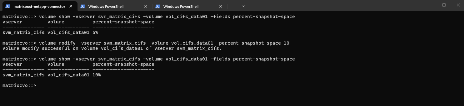
By using the ONTAP CLI to change the reserve for our CIFS volume (for example, setting it to 10%), run:
matrixcvo::> volume modify -vserver svm_matrix_cifs -volume vol_cifs_data01 -percent-snapshot-space 10

# Verify
matrixcvo::> volume show -vserver svm_matrix_cifs -volume vol_cifs_data01 -fields percent-snapshot-space
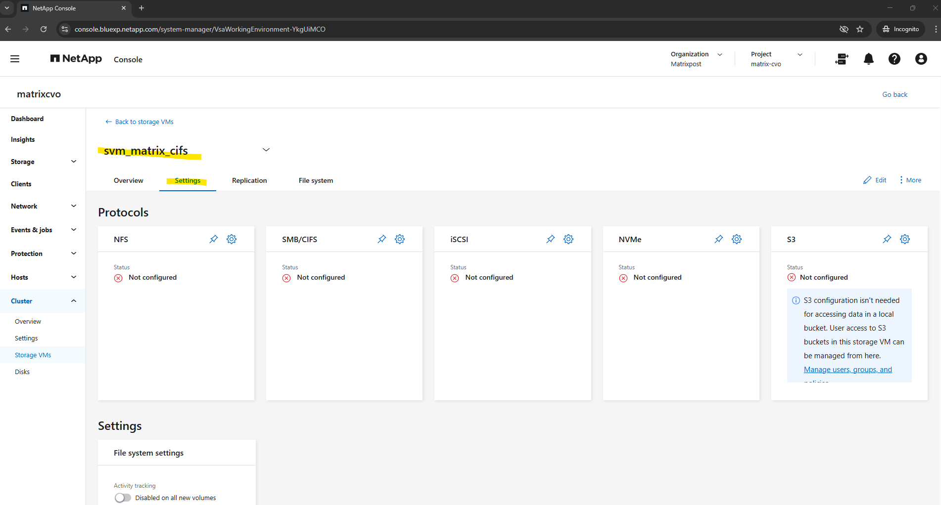
Publishing CIFS/SMB shares
By default, Cloud Volumes ONTAP creates a data SVM with NFS and iSCSI enabled. While it is technically possible to enable CIFS/SMB on this same SVM and join it to an Active Directory domain, this approach is mainly recommended just for lab or test environments.
In production scenarios, best practice is to create a separate SVM for SMB workloads to ensure clean separation of protocols, security contexts, and authentication domains.
Therefore I created further above a dedicated SVM just for cifs/SMB shares and named svm_matrix_cifs.
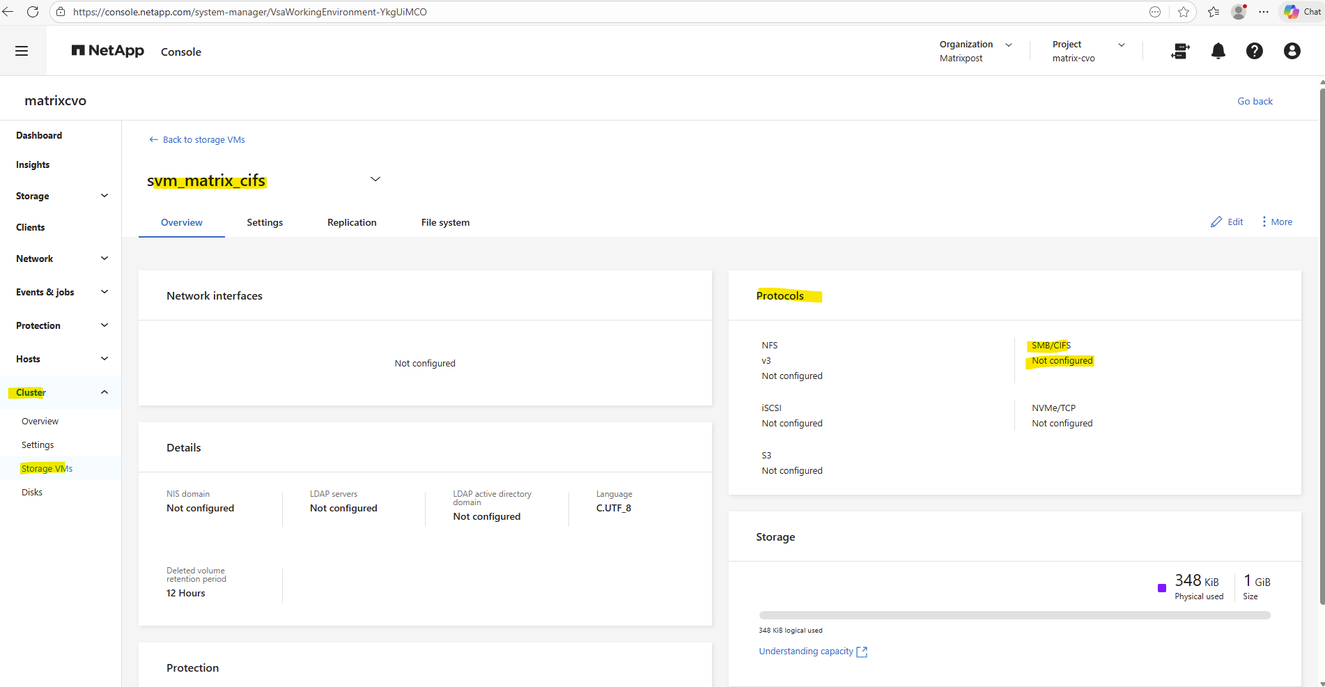
First we ensure if CIFS is already enabled on the SVM by running the following command.
matrixcvo::> vserver cifs show -vserver svm_matrix_cifs
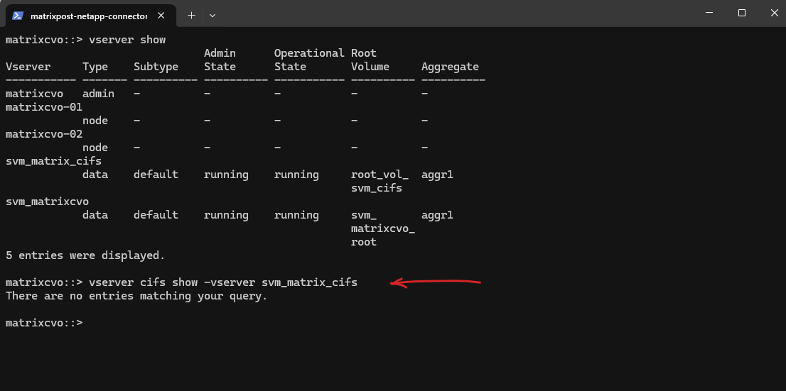
So far SMB/CIFS is not configured on this SVM.
So if it isn’t configured yet, we can enable it by running.
This requires the SVM to join an Active Directory domain.
vserver cifs create → Enables the CIFS (SMB) protocol service on the SVM
-vserver svm_matrix_cifs → The SVM where CIFS should be activated
-cifs-server cifs-matrix-cvo → The NetBIOS/hostname that Windows clients will see when they connect (\\cifs-matrix-cvo\share)
-domain matrixpost-lab.net → Joins this CIFS server to the specified Active Directory domainThe cifs-server named here cifs-matrix-cvo finally is the CIFS/SMB server object of the SVM. Think of it as: The Active Directory computer account that represents the SVM for SMB access.
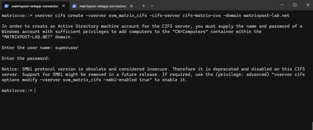
matrixcvo::> vserver cifs create -vserver svm_matrix_cifs -cifs-server cifs-matrix-cvo -domain matrixpost-lab.net
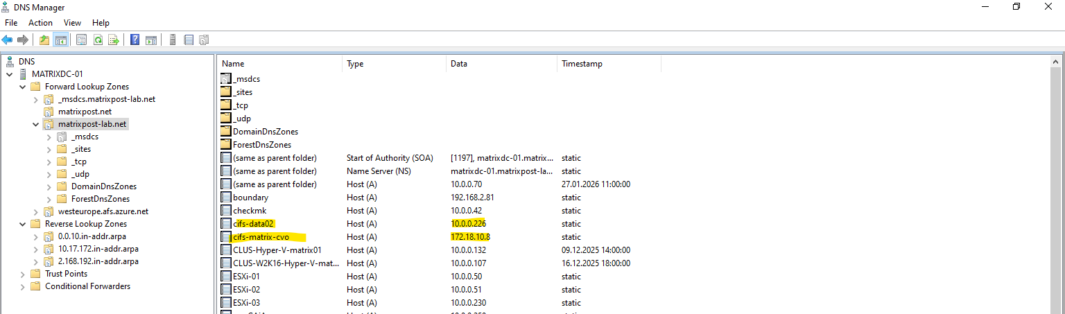
For the CIFS/SMB share (NetBIOS/hostname) I will create a DNS record in my lab environment which points to the IP address of the SVM we enabled CIFS on.
cifs-matrix-cvo with the IP address 172.18.10.8 is our SVM running on CVO in Azure. Below you can also see my SVM named cifs-data02 on which cifs is enabled and running in my on-prem vSphere lab environment like shown in my following post https://blog.matrixpost.net/step-by-step-guide-part-4-how-to-build-your-own-netapp-ontap-9-lab-day-to-day-operations/.
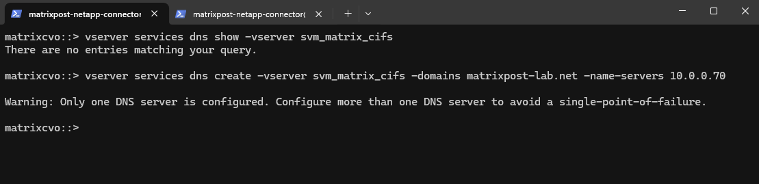
I will also need to set a DNS server first on the Vserver’s DNS configuration.
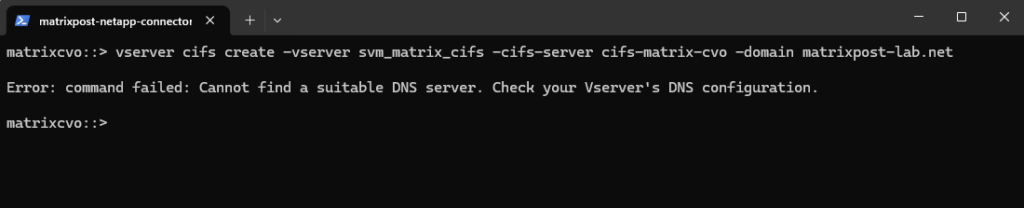
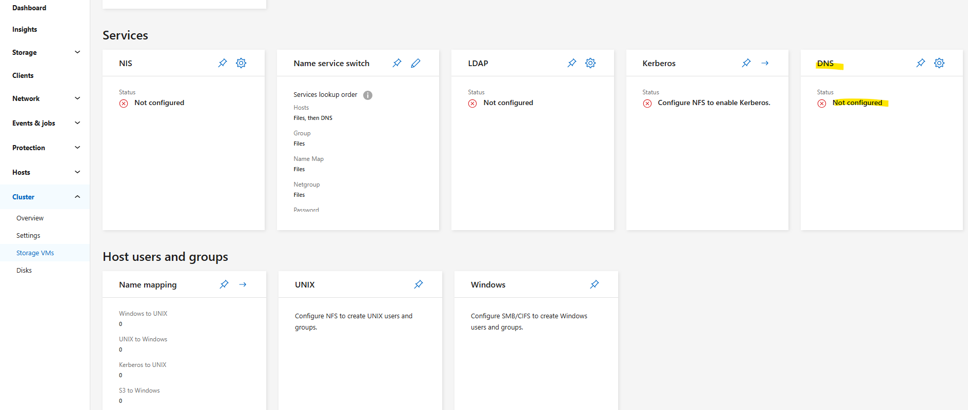
We can configure it by using the CLI or the System Manager GUI. Below we will see by using the CLI.
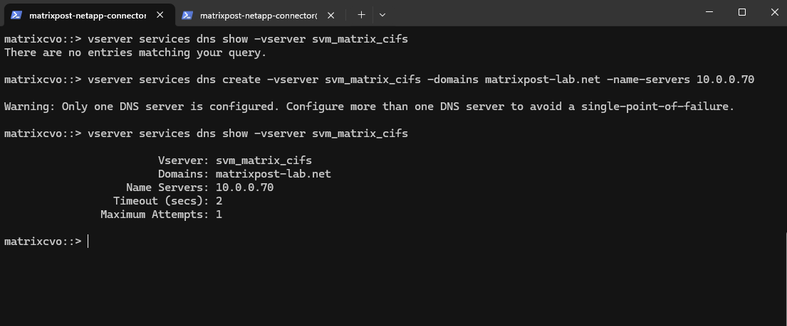
matrixcvo::> vserver services dns show -vserver svm_matrix_cifs
matrixcvo::> vserver services dns create -vserver svm_matrix_cifs -domains matrixpost-lab.net -name-servers 10.0.0.70
For my lab environment just one DNS server is fine.
matrixcvo::> vserver services dns show -vserver svm_matrix_cifs
Let’s try it again.
matrixcvo::> vserver cifs create -vserver svm_matrix_cifs -cifs-server cifs-matrix-cvo -domain matrixpost-lab.net
For the domain join and to create a AD machine account for this CIFS server we need to supply the name and password of a Windows account with sufficient privileges to add computers to the AD.
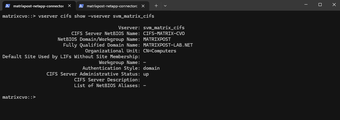
Our new CIFS server is joined to our AD and the default Computers container.
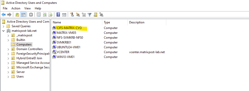
Looks good.
matrixcvo::> vserver cifs show -vserver svm_matrix_cifs
How it works finally that this SVM can reach and connect to my on-premise Active Directory and domain controller, we will see in the section below about VNet Peering and Site-to-Site VPN connection with my on-prem network.
We can now mount our previously created new volume named vol_cifs_data01 in the namespace of our newly created SVM named svm_matrix_cifs.
Mounting a volume in the namespace in NetApp ONTAP is a key concept, especially when working with NAS protocols like NFS and SMB.
In ONTAP, each SVM (Storage Virtual Machine) has its own namespace, which is essentially a virtual file system tree made up of Mounted volumes (like mount points) and Junction paths (like folders or subdirectories).
This allows ONTAP to present multiple volumes as a unified file system to clients.
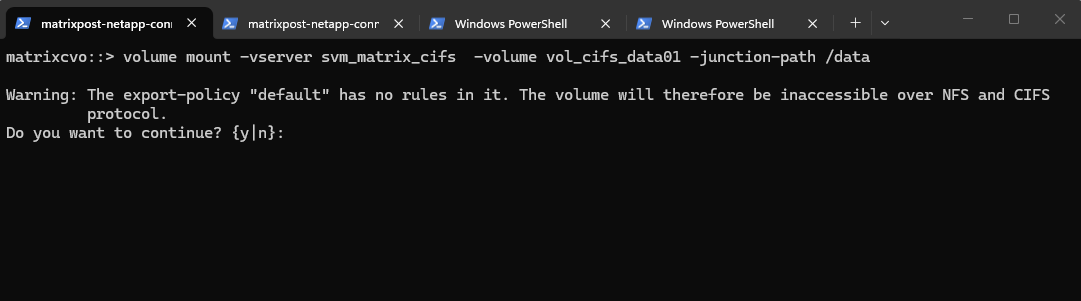
matrixcvo::> volume mount -vserver svm_matrix_cifs -volume vol_cifs_data01 -junction-path /data
Warning: The export-policy “default” has no rules in it. The volume will therefore be inaccessible over NFS and CIFS protocol.
Since we plan to use this volume exclusively for CIFS/SMB access, the warning can be safely ignored and confirmed with yes. The message primarily refers to NFS access, as export policies control NFS permissions, while SMB access is governed by share configuration and NTFS permissions in a standard ONTAP setup.
Export policy enforcement for SMB is disabled by default but can be enabled if required to restrict access based on authentication protocol, client IP addresses, or host names as shown further down.
By default, export-policy enforcement for CIFS/SMB is disabled in ONTAP, meaning export policies are not evaluated for CIFS access.
This also applies to the default export policy, so it can safely be ignored when using SMB shares.
Access control is handled exclusively through share permissions and NTFS ACLs unless export-policy enforcement is explicitly enabled.
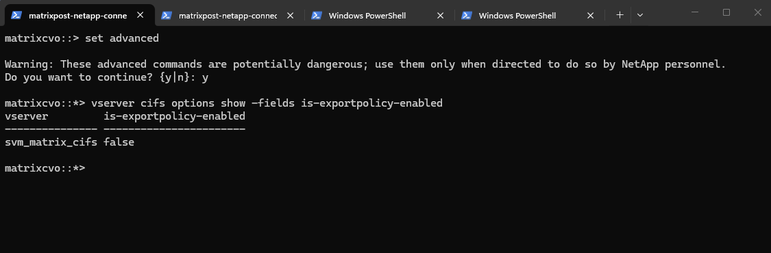
ONTAP does provide the option to configure export-policy check for CIFS. When the CIFS option
"is-exportpolicy-enabled"istrueyou do need to create export-policy rules for CIFS protocol access.Source: https://kb.netapp.com/on-prem/ontap/da/NAS/NAS-KBs/Are_export_policy_rules_necessary_for_CIFS_access
matrixcvo::> set advanced
matrixcvo::*> vserver cifs options show -fields is-exportpolicy-enabled
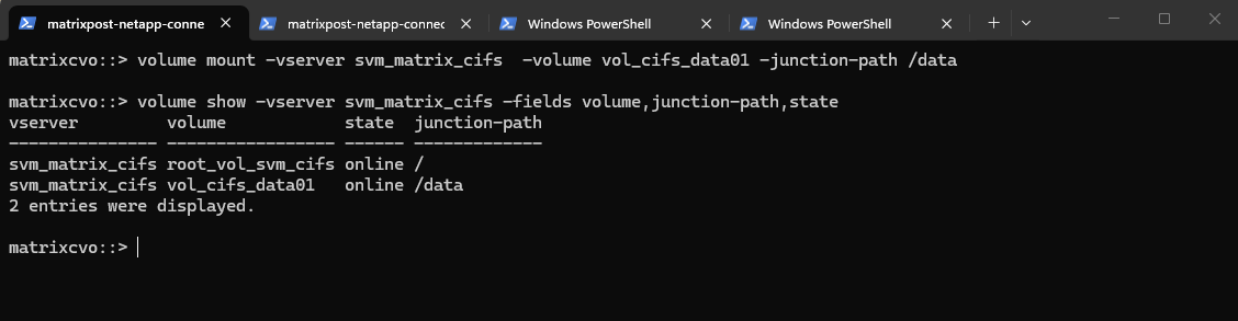
We can verify the mounted volume by running:
matrixcvo::> volume show -vserver svm_matrix_cifs -fields volume,junction-path,state
The volume is now mounted under the SVM namespace and ready to be shared via SMB or NFS, completing the storage preparation for client access.
From now on SMB clientss can access it via via CIFS: \\<svm-lif-ip>\DataShare.
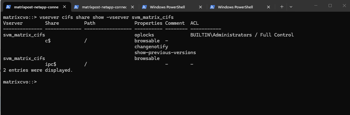
We can run the following command to show the currently existing CIFS shares on our SVM.
c$ and ipc$ shares here are default administrative shares, very similar to those found on a Windows server.
They are pointing to the root of the SVM namespace, which is the
root_vol_svm_cifs, not our newly mounted volume vol_cifs_data01.
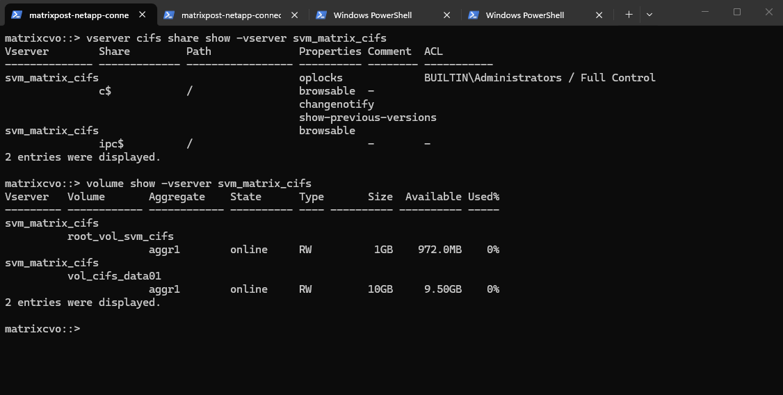
matrixcvo::> vserver cifs share show -vserver svm_matrix_cifs
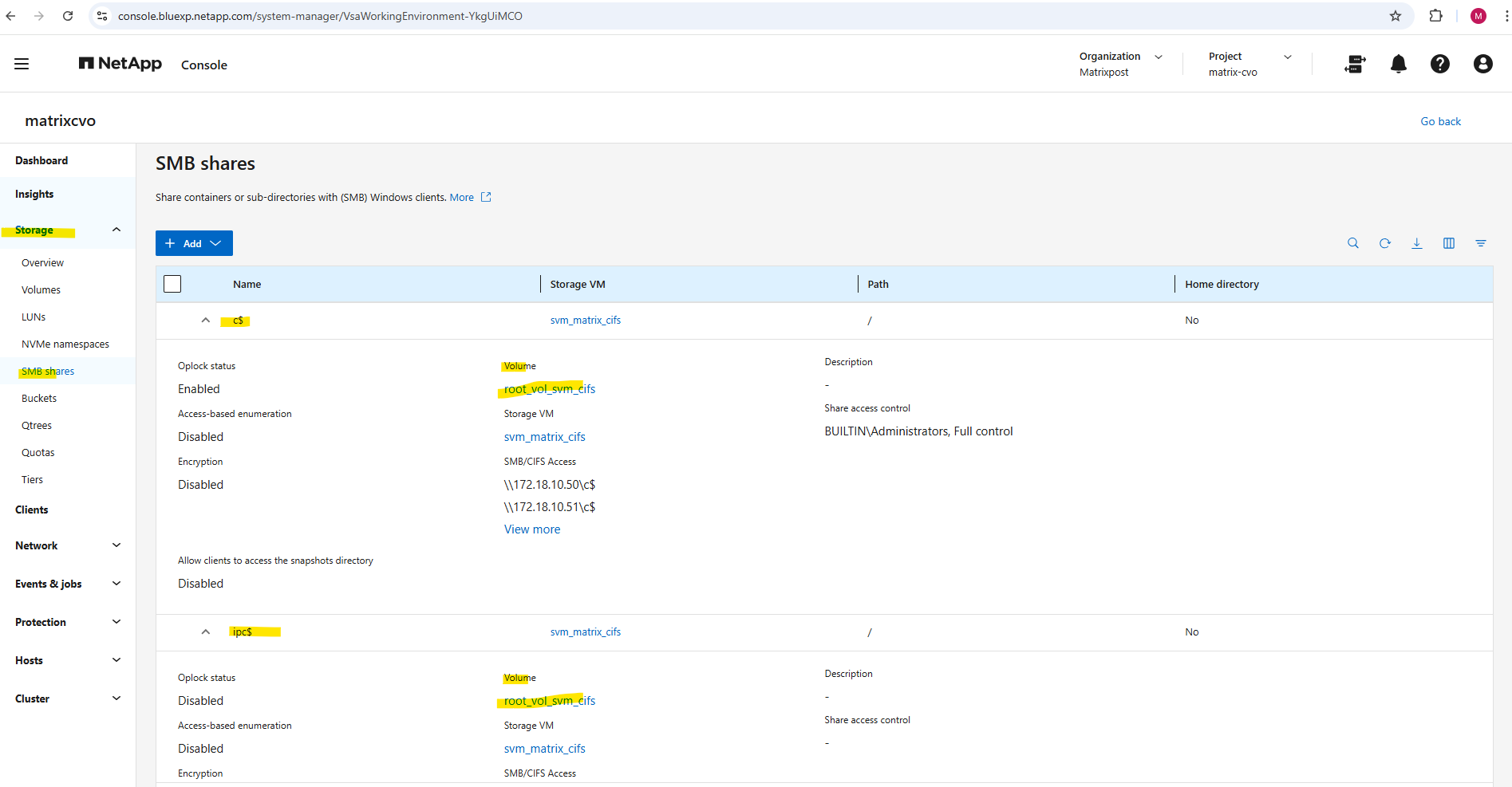
Below we can see the
root_vol_svm_cifsvolume which includes the above mentioned c$ and ipc$ shares (default administrative shares).
Every SVM in ONTAP requires a root volume, often named something like root_vol_svm_<custom name>. This root volume is mounted at / in the SVM’s namespace.
Our new volume vol_cifs_data01 is mounted at /data, but unless it’s explicitly shared, it’s not exposed via SMB.
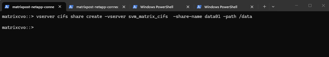
We now need to create an SMB share for our newly created vol_cifs_data01 volume.
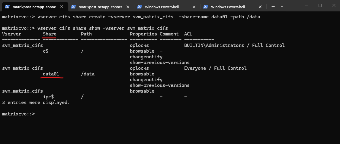
matrixcvo::> vserver cifs share create -vserver svm_matrix_cifs -share-name data01 -path /data
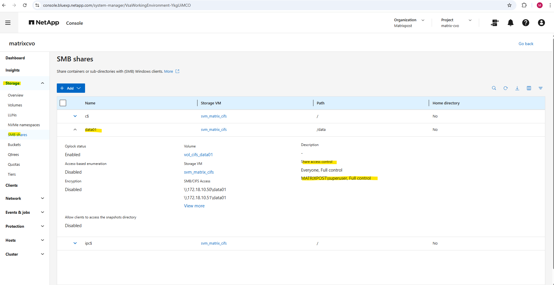
By running the command to list all CIFS shares on a specific SVM (Storage Virtual Machine) in NetApp again, we will now see our newly created data01 share.
matrixcvo::> vserver cifs share show -vserver svm_matrix_cifs
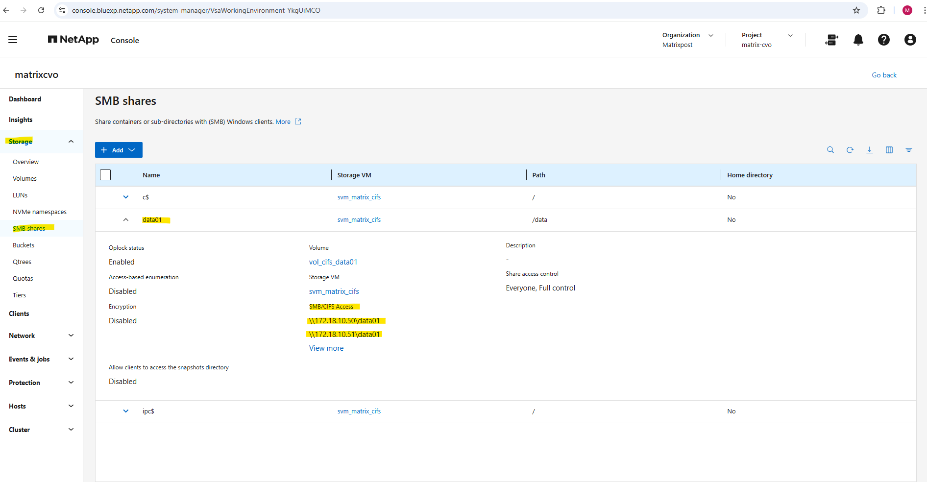
In the System Manager we will see the mount path or our new SMB share.
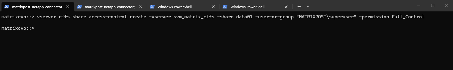
And finally we need to set the share permissions.
For my lab environment I will assign here just my enterprise admin with full control.
matrixcvo::> vserver cifs share access-control create -vserver svm_matrix_cifs -share data01 -user-or-group "MATRIXPOST\superuser" -permission Full_Control
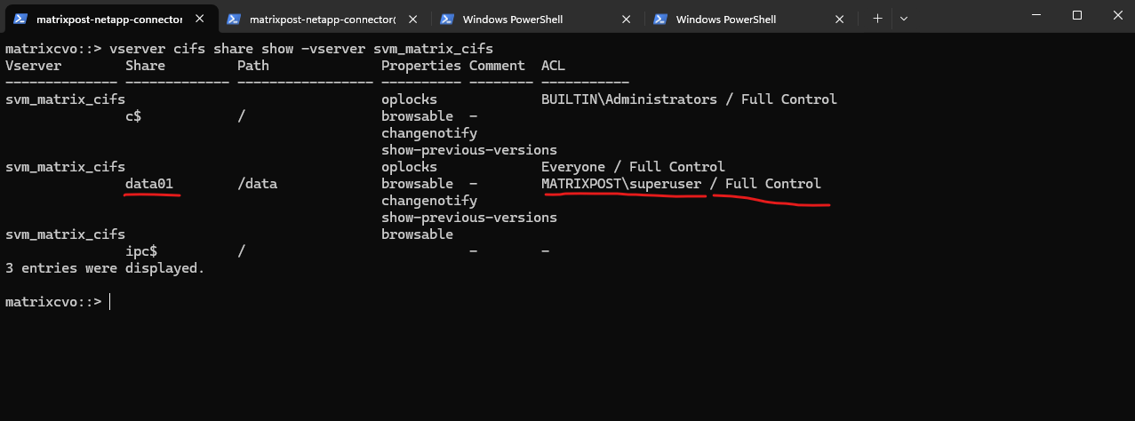
We can verify them by running:
matrixcvo::> vserver cifs share show -vserver svm_matrix_cifs
By default, when ONTAP creates an SMB share: It assigns Everyone / Full Control at the share level. Actual security is enforced by NTFS permissions, not the share ACL.
By default, the share-level ACL gives full control to the standard group named Everyone.
Full control in the ACL means that all users in the domain and all trusted domains have full access to the share. You can control the level of access for a share-level ACL by using the Microsoft Management Console (MMC) on a Windows client or the ONTAP command line.
Source: https://docs.netapp.com/us-en/ontap/smb-admin/manage-smb-level-acls-concept.html
In the System Manager GUI we will also see our newly added share permissions.
Here we also see the full SMB path to finally mount the share on our clients.
Unfortunately, in the ONTAP CLI, we do have to manually piece together the full SMB share path information that the System Manager GUI shows automatically in a nice, human-readable way.
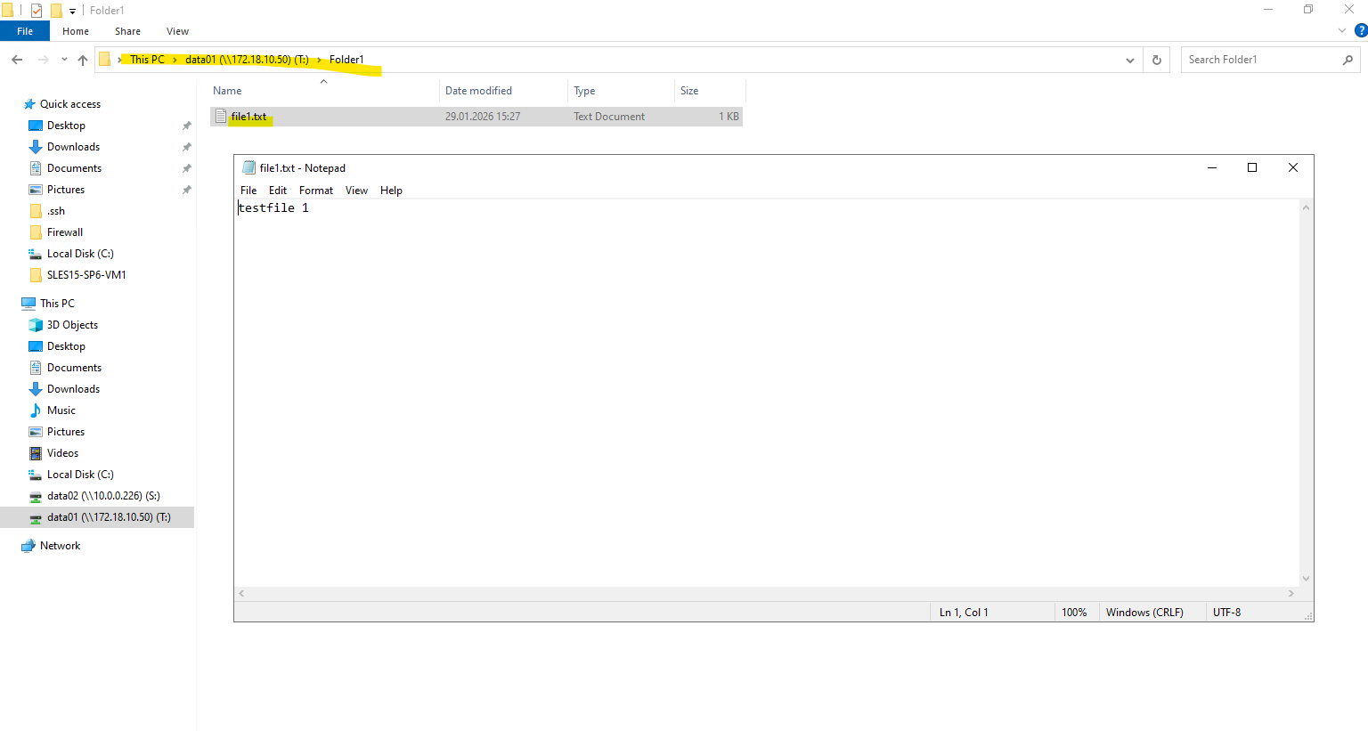
We can now mount our new SMB share when using an account we have authorized previously, in my case this is the enterprise admin named superuser.
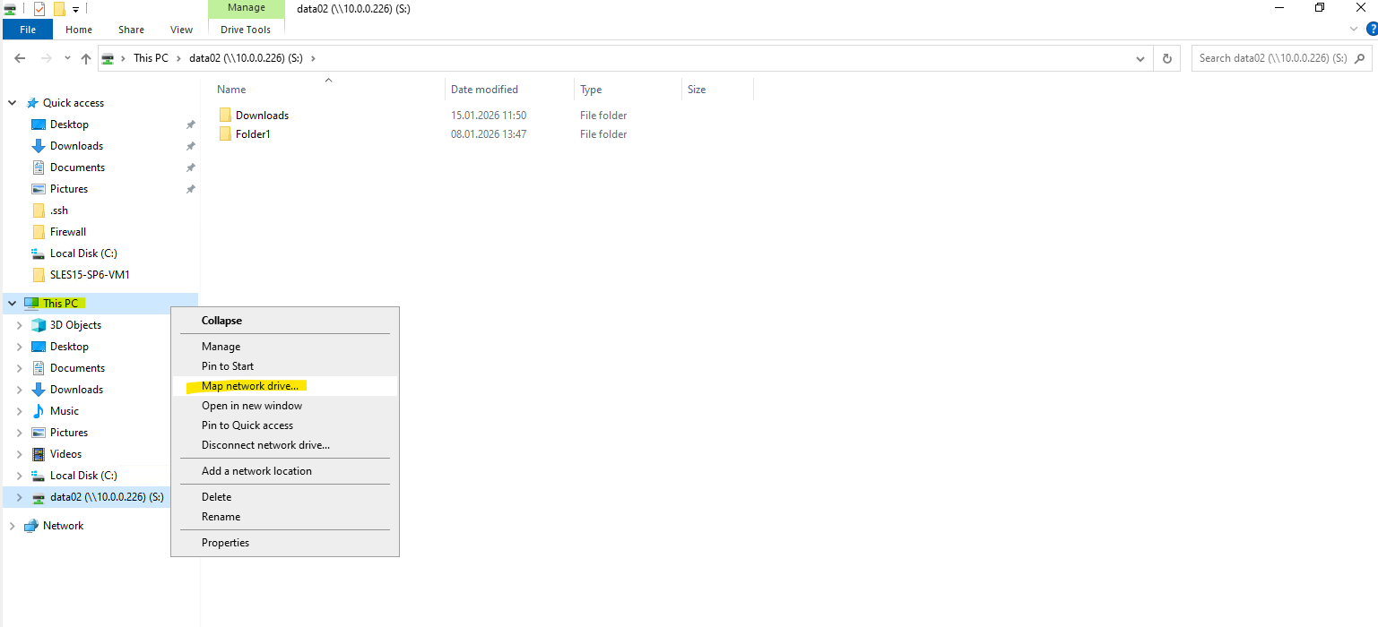
For the folder we need to enter the mount path of our new SMB share shown above.
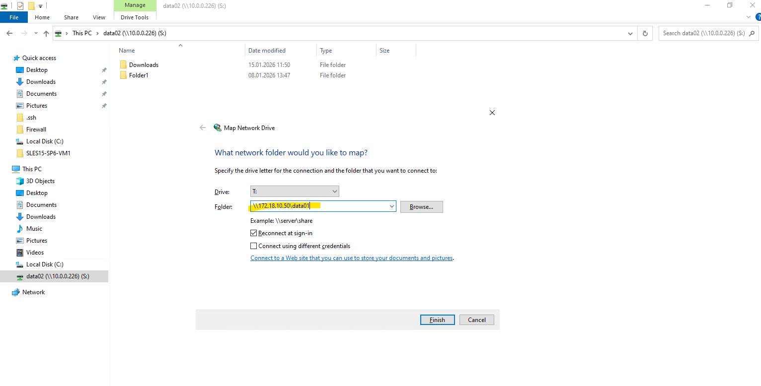
Looks good!
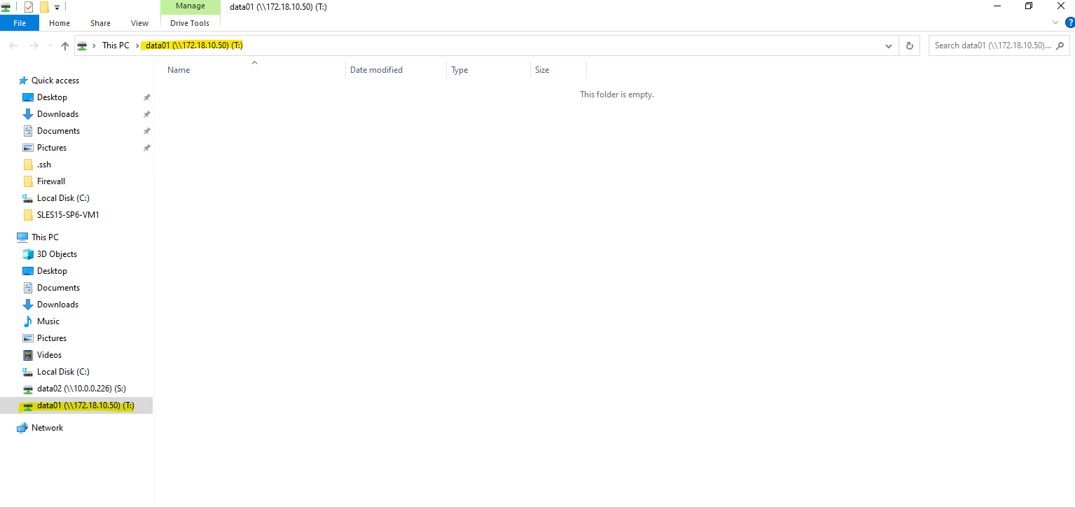
I am also able to create a folder and file on the new share.
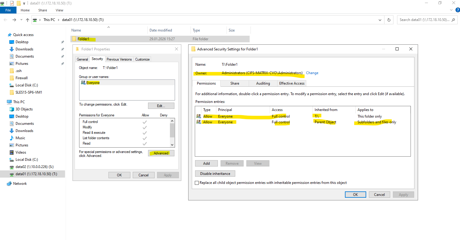
Creating a CIFS share only controls access to the share itself. NTFS permissions are applied at the filesystem level and are independent of share permissions.
By default, ONTAP assigns full control to the local Administrators group, which is expected behavior for newly created NTFS volumes.
After creating the SMB share, the NTFS permissions still need to be adjusted. This is done by mounting the share from a Windows system and modifying the security settings directly via Windows Explorer, as NTFS permissions are managed at the filesystem level and not through ONTAP CLI. This approach ensures proper ownership, inheritance, and access control for users and groups.
Enable or disable ONTAP export policies for SMB access
We can enable or disable export policies for SMB access on storage virtual machines (SVMs). Using export policies to control SMB access to resources is optional.
The following are the requirements for enabling export policies for SMB:
- The client must have a “PTR” record in DNS before you create the export rules for that client.
- An additional set of “A” and “PTR” records for host names is required if the SVM provides access to NFS clients and the host name you want to use for NFS access is different from the CIFS server name.
When setting up a new CIFS server on your SVM, the use of export policies for SMB access is disabled by default.
You can enable export policies for SMB access if you want to control access based on authentication protocol or on client IP addresses or host names. You can enable or disable export policies for SMB access at any time.
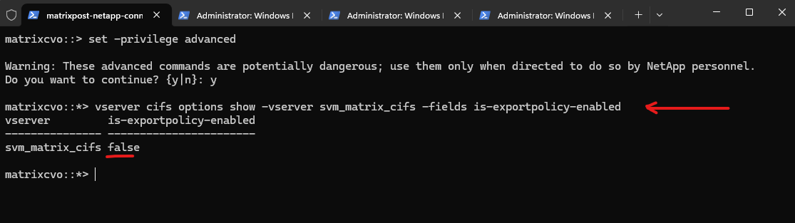
By switching to advanced privilege level and checking the CIFS options, we can see that is-exportpolicy-enabled is set to false for svm_matrix_cifs. This confirms that SMB access is not evaluated against export policy rules in this configuration. Instead, access control is handled exclusively through CIFS share settings and NTFS permissions.
matrixcvo::> vserver cifs options show -vserver svm_matrix_cifs
matrixcvo::> set -privilege advanced
matrixcvo::*> vserver cifs options show -vserver svm_matrix_cifs -fields is-exportpolicy-enabled
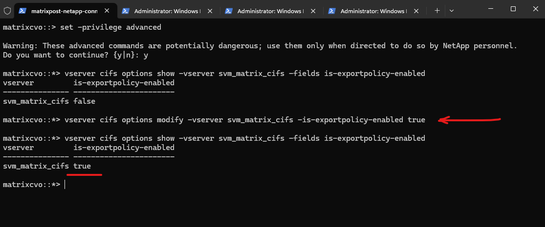
We can enable export policies for SMB access by running the following command.
matrixcvo::*> vserver cifs options modify -vserver svm_matrix_cifs -is-exportpolicy-enabled true
Source: https://docs.netapp.com/us-en/ontap/smb-admin/enable-disable-export-policies-task.html
Configure NFS Export on ONTAP
In the following section, we prepare ONTAP for NFS access by building a dedicated Storage Virtual Machine (SVM) and configuring the required networking components, including management and data LIFs behind an Azure Internal Load Balancer.
After creating and mounting the volume within the SVM namespace, the environment is ready for NFS exports, enabling secure and efficient client connectivity.
An NFS export in NetApp is a volume (or path) made accessible to NFS clients through an SVM, using a combination of:
- a mounted volume (junction path)
- a logical interface (LIF)
- and an export policy
Unlike in Linux where /etc/exports defines NFS access, NetApp uses export policies and rules at the volume level to control who can access what, and how.
Like previously for publishing CIFS/SMB shares, I will first create a new SVM which I will use dedicated for NFS exports.
Create a Storage Virtual Machine (SVM) for NFS Exports
To provide NFS access, a dedicated Storage Virtual Machine (SVM) is created to logically separate storage resources and protocols. The SVM acts as the tenant for data services, allowing you to manage networking, security, and export policies independently from other workloads.
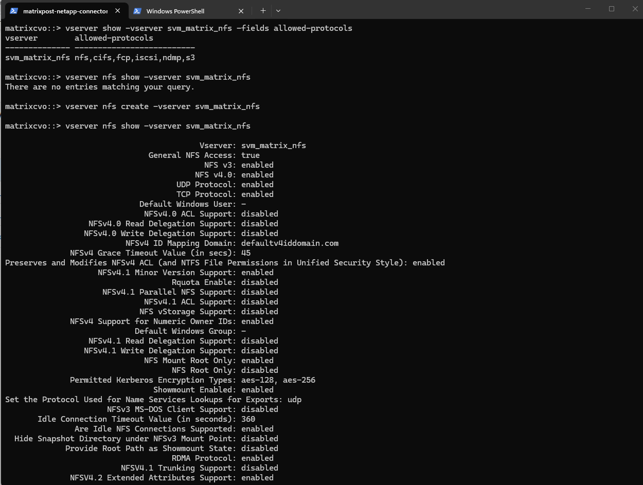
matrixcvo::> vserver create -vserver svm_matrix_nfs -aggregate aggr1 -rootvolume root_vol_svm_nfs -rootvolume-security-style unix
So far NFS is not enabled on our newly created Storage Virtual Machine (SVM).
To enable we need to run:
matrixcvo::> vserver nfs create -vserver svm_matrix_nfs

# check if NFS is enabled
matrixcvo::> vserver nfs show -vserver svm_matrix_nfs
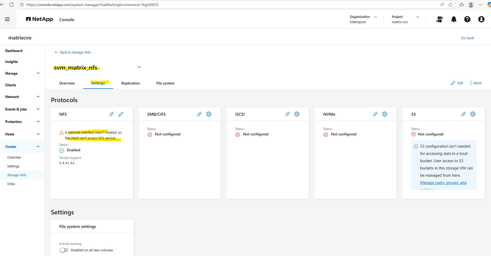
After creating a new SVM, no network interfaces (LIFs) are configured by default, which means the NFS service is not yet reachable by clients.
A data LIF must first be created and assigned an IP address so the SVM can accept incoming NFS connections. Without a properly configured LIF, the storage remains operational internally but inaccessible from the network.
To create a management LIF for our new SVM, we need to run the following command.
Just like we did for the CIFS management and data LIFs, we are now applying the same failover policy and unique probe ports to the NFS management and data interfaces.
The
default-managementservice policy specifically authorizes the LIF for administrative tasks like SSH and HTTPS while logically isolating it from data protocols. By pairing this with thesystem-definedfailover policy, ONTAP ensures the management interface can automatically relocate to any available port in the broadcast domain during a node failure.The
-probe-port 63008parameter enables a dedicated TCP listener on the LIF that allows the Azure Internal Load Balancer to perform health checks, ensuring that traffic is only routed to the node where the LIF is currently active.
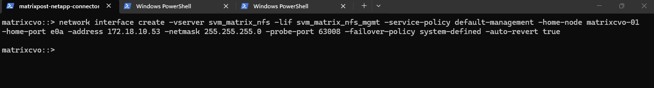
matrixcvo::> network interface create -vserver svm_matrix_nfs -lif svm_matrix_nfs_mgmt -service-policy default-management -home-node matrixcvo-01 -home-port e0a -address 172.18.10.53 -netmask 255.255.255.0 -probe-port 63008 -failover-policy system-defined -auto-revert true
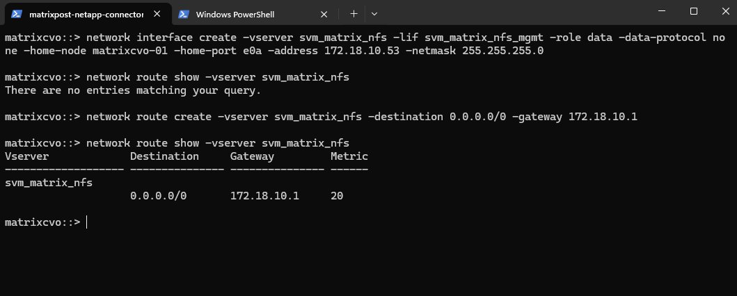
Before continuing, it’s important to verify whether a default route already exists for the new SVM, if missing create it. Finally the same as previously for the CIFS SVM.
matrixcvo::> network route show -vserver svm_matrix_nfs
matrixcvo::> network route create -vserver svm_matrix_nfs -destination 0.0.0.0/0 -gateway 172.18.10.1
Azure Internal Load Balancer Configuration for the Management LIF
After creating the management LIF on the SVM, it is not reachable automatically, not even from within the same subnet. This also true for LIFs in general created for Cloud Volume ONTAP nodes in Azure.
More about we already covered further above when creating the CIFS SVM.
Since the configuration approach is identical for the NFS SVM, it is not covered again in detail.
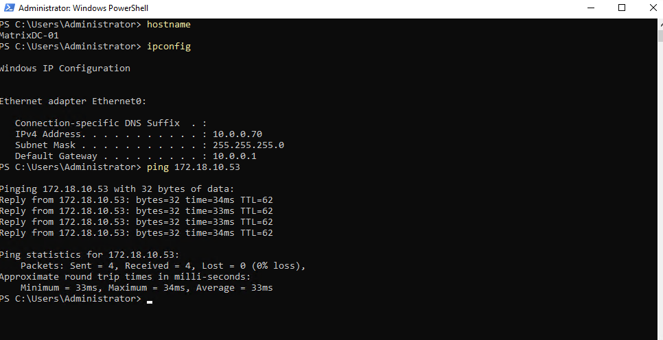
A quick check if I can reach the management LIF from my on-prem environment already.
Looks good!
Create the Data LIFs for the new SVM
Each SVM requires at least one data LIF, which represents the network endpoint used by clients to access storage services such as NFS or SMB. The LIF defines the IP address, subnet, and network path used by the SVM.
Since the configuration approach is identical for the NFS SVM, it is not covered again in detail.
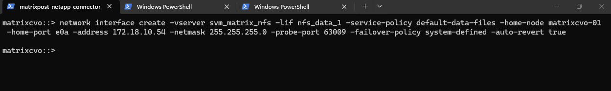
matrixcvo::> network interface create -vserver svm_matrix_nfs -lif nfs_data_1 -service-policy default-data-files -home-node matrixcvo-01 -home-port e0a -address 172.18.10.54 -netmask 255.255.255.0 -probe-port 63009 -failover-policy system-defined -auto-revert true
In HA setups, it is recommended to create one data LIF per node.
We should create two LIFs, one per node, with different names and IPs.
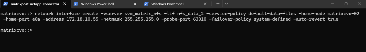
matrixcvo::> network interface create -vserver svm_matrix_nfs -lif nfs_data_2 -role data -data-protocol nfs -home-node matrixcvo-02 -home-port e0a -address 172.18.10.55 -netmask 255.255.255.0 -probe-port 63010 -failover-policy sfo-partner-only -auto-revert true
After creating the data LIFs, the SVM now has one active data interface per node. This setup follows NetApp best practices for high availability.
matrixcvo::> network interface show -vserver svm_matrix_nfs

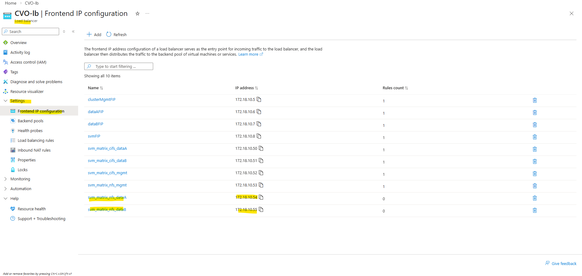
Azure Internal Load Balancer Configuration for the data LIFs
After creating the data LIFs in ONTAP, the next step is to add the corresponding IP addresses to the Azure internal load balancer.
Since the configuration approach is identical for the NFS SVM, it is not covered again in detail.
Create a Volume
After creating and configuring a SVM, the next step is to create a new volume that will be used to store and present data to clients.
The volume must be created on the correct SVM and mounted into its namespace so it can later be shared via SMB and/or NFS.
A volume in NetApp ONTAP is a logical, mountable unit of storage that resides inside an aggregate, is served by a Storage Virtual Machine (SVM), and is accessible to clients via NFS, SMB, iSCSI, or FC.
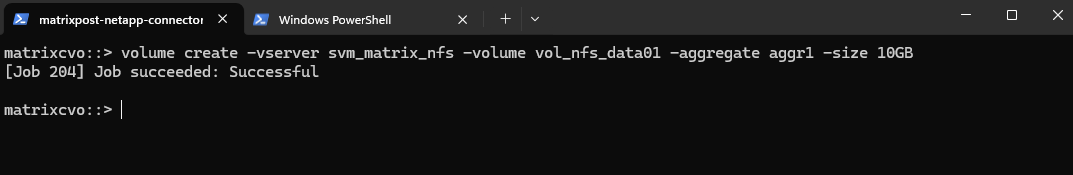
Below we will create a 10 GB data volume called vol_nfs_data01 on aggr1.
matrixcvo::> volume create -vserver svm_matrix_nfs -volume vol_nfs_data01 -aggregate aggr1 -size 10GB
We can check the creation by running.
matrixcvo::> volume show -vserver svm_matrix_nfs
matrixcvo::> volume show -volume vol_nfs_data01 -instance
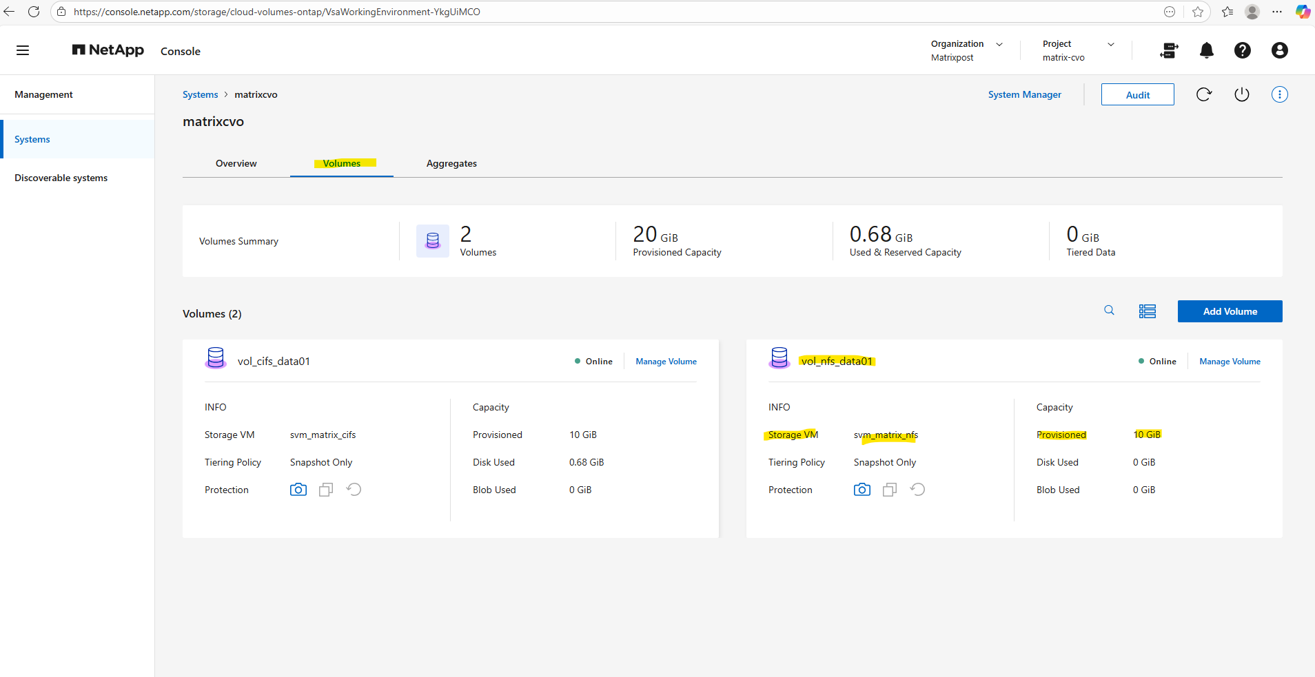
Or by using the ONTAP System Manager and here within Storage -> Volumes.
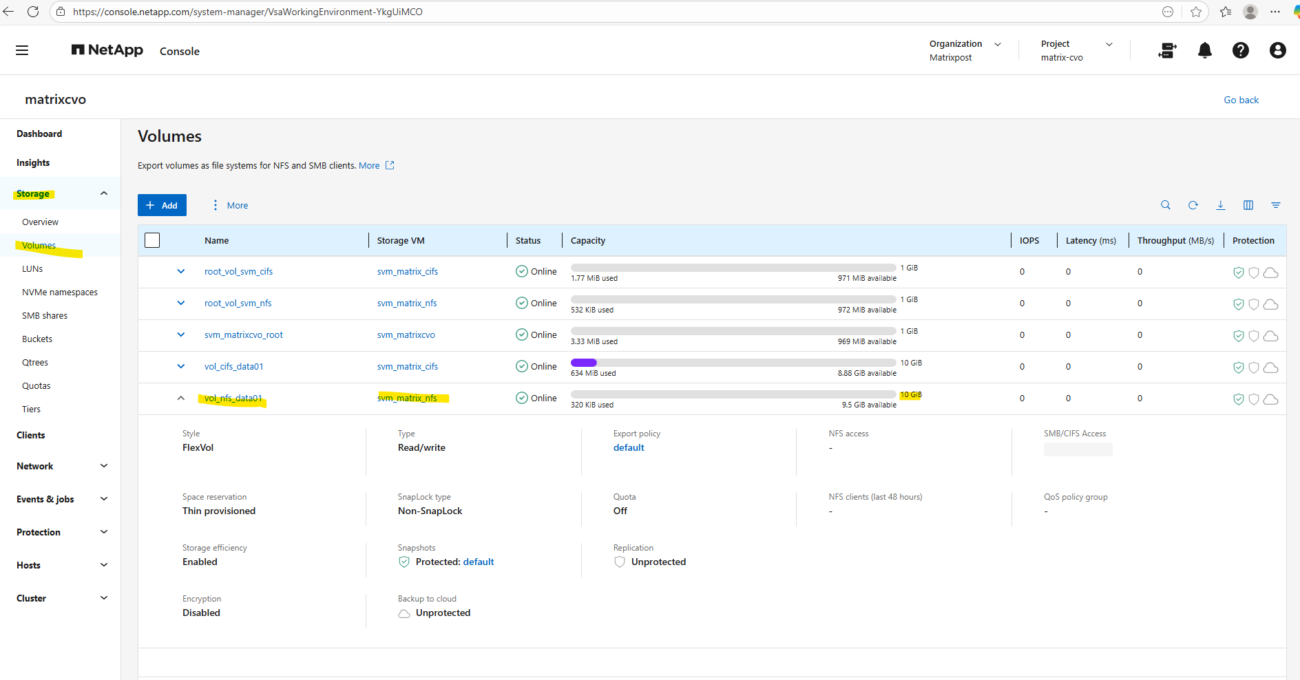
And also by using the NetApp console under Storage -> Management -> Systems, here select our system and click on the right bar on Enter System.
Within the Volumes tab we will find our newly created volume named vol_nfs_data01.
Mounting the ONTAP Volume on the SVM
Now we need to mount the ONTAP volume to a path within our new previously created SVM used for NFS exports.
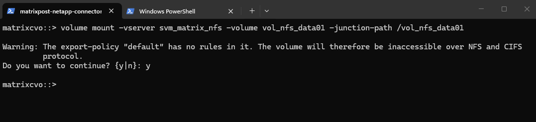
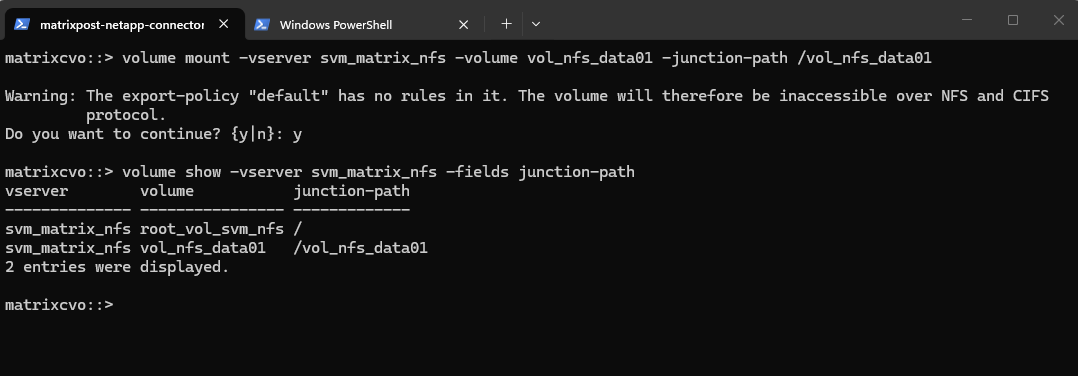
matrixcvo::> volume mount -vserver svm_matrix_nfs -volume vol_nfs_data01 -junction-path /vol_nfs_data01
Checking the mount.
matrixcvo::> volume show -vserver svm_matrix_nfs -fields junction-path
As shown in the warning message during the mount above, so far no rules are created in the SVM’s default policy. So even if we create a new dedicated export policy for our volume, the NFS access won’t work.
In ONTAP, every volume exists in the namespace hierarchy of the SVM. Even though you’re mounting a specific volume, ONTAP still checks the export policy on the root volume to allow traversal to the volume’s junction point.
The best practice for a secure CVO environment is a two-tier approach.
Because ONTAP uses a junction path (a folder-like hierarchy), a client must have “read” access to the SVM Root Volume just to see the path, and then specific permissions on the Data Volume to actually do work.
The Junction Door (SVM Root): Usually uses the
defaultexport policy. It only needs to allow read-only access so clients can “traverse” the root directory to find their specific mount point.The Work Zone (Data Volume): This is where we apply our dedicated policy (like my
nfs_policybelow). This grants the specific read-write permissions and Superuser (root) access only to the authorized IPs or subnets.
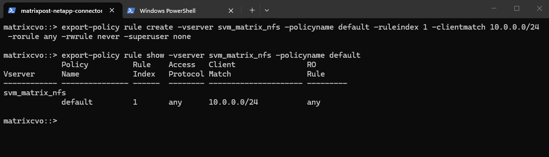
To ensure traversal from the namespace root to volumes (even when those volumes use their own export policies), the default export policy assigned to the SVM’s root volume must allow at least read-only access for the client by running the following command.
matrixcvo::> export-policy rule create -vserver svm_matrix_nfs -policyname default -ruleindex 1 -clientmatch 10.0.0.0/24 -rorule any -rwrule never -superuser none
matrixcvo::> export-policy rule show -vserver svm_matrix_nfs -policyname default
Clients matching this rule (IP address within my internal subnet 10.0.0.0/24) will be granted read-only access regardless of their authentication type. This includes sys (UNIX), krb5 (Kerberos), ntlm (NTLM), or even none (unauthenticated).
So No explicit authentication is required by this rule’s rorule. The any option means that the client can use any authentication method (or no authentication at all) and still be granted read-only access.
The primary verification for this read-only access is just the client IP address (which must matching to be within the subnet 10.0.0.0/24).
-superuser none: Any client attempting to access the volume as UID 0 (root) will not be granted superuser privileges. Instead, they will be “squashed” to the anonymous user ID.
The Rule Index determines the specific order in which ONTAP evaluates access requirements, where the system processes rules sequentially starting from index 1 until it finds a match for the connecting client’s IP address.
When configuring multiple rules within a single export policy, each rule must be assigned a unique Rule Index to define its priority, as ONTAP evaluates the list in ascending numerical order and stops as soon as it finds the first match for a client.
Before we can create a new policy rule with the export-policy rule create command shown above, we first need to determine the next free rule index number by using the vserver export-policy rule show command shown below.
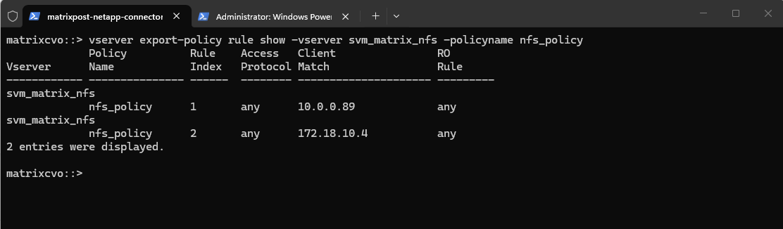
So in case we want to add another export-policy rule for this SVM and export policy, we need to use for the rule index here 3. This outpout is just for demonstration purpose when having multiple rules here, further below I will create the first rule for the newly created export policy.
matrixcvo::> vserver export-policy rule show -vserver svm_matrix_nfs -policyname nfs_policy
To allow access to a volume with its own export policy, the SVM root volume’s export policy (typically default) must:
- Allow read-only (ro=sys) access
- Match the client’s IP
- Be applied to the correct root volume
Now we can create our own policy here and adding a rule to allow NFS clients also read-write access to the NFS export.
matrixcvo::> export-policy create -vserver svm_matrix_nfs -policyname nfs_policy

# We can delete it again with
cluster01::> export-policy delete -vserver svm_matrix_nfs -policyname nfs_policy
Add a rule (e.g., allow all NFS clients). Here I will allow in general all users on the NFS client with the IP address 10.0.0.89 read-write access to the volume (we first need to apply the policy to our volume).
The rule index with 1 below because this is our first rule for the newly created export policy and therefore is the very first one ONTAP checks.
matrixcvo::> export-policy rule create -vserver svm_matrix_nfs -policyname nfs_policy -ruleindex 1 -clientmatch 10.0.0.89 -rorule any -rwrule any

# to avoid (disable) root squash, adding here ==> -superuser any ==> More about root squash in Part 5
matrixcvo::> export-policy rule create -vserver svm_matrix_nfs -policyname nfs_policy -ruleindex 1 \
  -clientmatch 10.0.0.89 -rorule any -rwrule any -superuser any

# to enable root squash explicitly use
-superuser none

# in some instances if null authentication (sec=null) is used (more about sec=null in Part 5), it would be required to use the uid configured in the anon=<user id> field. Using -anon 0 for example maps anonymous users all to UID 0 (root)
matrixcvo::> vserver export-policy rule modify -vserver svm_matrix_nfs -policyname nfs_policy -ruleindex 1 -anon 0
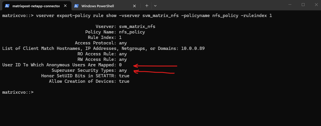
By running the following command we can determine if root squash is enabled.
Superuser Security Types:
none (default) ==> Root is squashed (UID 0 → UID 65534)
any ==> Root is not squashed; retains UID 0
krb5 ==> Root not squashed for Kerberos-auth NFSUser ID To Which Anonymous Users Are Mapped:
0 ==> map anonymous users to UID 0 (root)
65535 ==> map anonymous users to UID 65534 (nobody)
matrixcvo::> vserver export-policy rule show -vserver svm_matrix_nfs -policyname nfs_policy -ruleindex 1
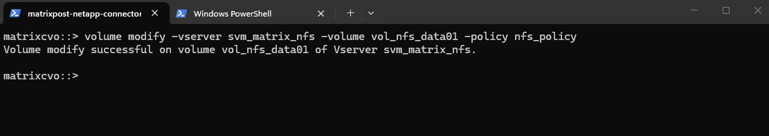
Finally applying the export policy to our new volume.
matrixcvo::> volume modify -vserver svm_matrix_nfs -volume vol_nfs_data01 -policy nfs_policy
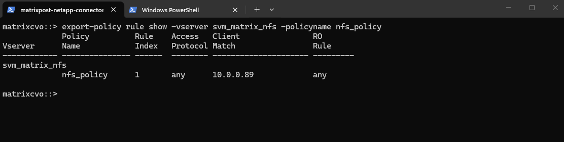
We can verify the export status of a SVM’s export policy by running.
matrixcvo::> export-policy rule show -vserver svm_matrix_nfs -policyname nfs_policy
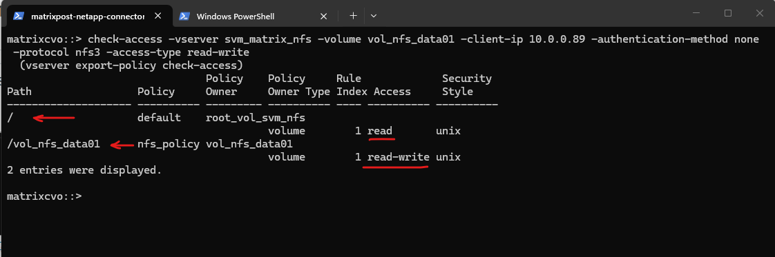
In ONTAP we can also simulate an access to check if a specific client can access the NFS export by using the following command.
The
vserver export-policy check-accesscommand is a vital troubleshooting tool that simulates a client’s connection to verify if our Export Policies actually allow the intended traffic.In this output, it confirms that while the root of the SVM only allows read access, the specific path for
vol_nfs_data01correctly grants the client at10.0.0.89the read-write permissions required for NFSv3 operations. This “bottom-up” validation ensures that even if our Azure Network Security Groups (NSGs) are open, the internal ONTAP policies aren’t silently blocking our Linux workloads.
matrixcvo::> check-access -vserver svm_matrix_nfs -volume vol_nfs_data01 -client-ip 10.0.0.89 -authentication-method none -protocol nfs3 -access-type read-write
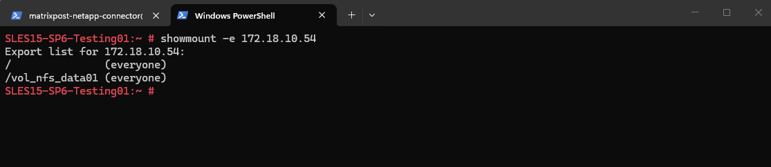
We can now also check from a client which exports exposed by running the showmount command below. The IP address is from our Storage Virtual Machine (SVM) which exposes the NFS export.
For the NFS Server I will use the IP address for the data LIF on node A which is 172.18.10.54.
-e stands for exports. It asks the NFS server’s mountd daemon for a list of currently available shared directories (exports).
showmount is a client-side tool querying an NFSv2 or NFSv3 server. It won’t work for NFSv4 servers, as NFSv4 doesn’t use mountd for exporting filesystems.
# showmount -e <NFS Server>
# showmount -e 172.18.10.54
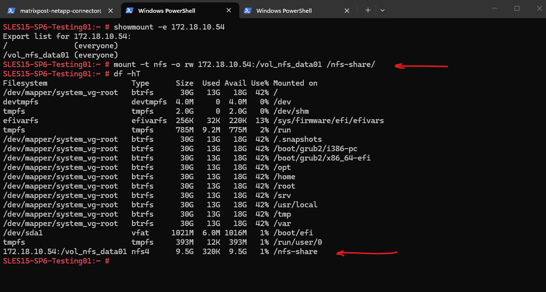
And finally mount the volume to access and write to.
SLES15-SP6-Testing01:~ # mount -t nfs -o rw 172.18.10.54:/vol_nfs_data01 /nfs-share/
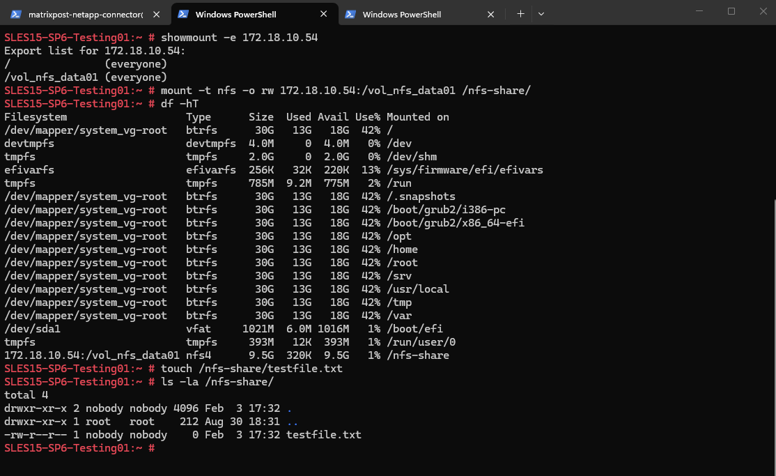
We are also able to create a new file on the mounted NFS export.
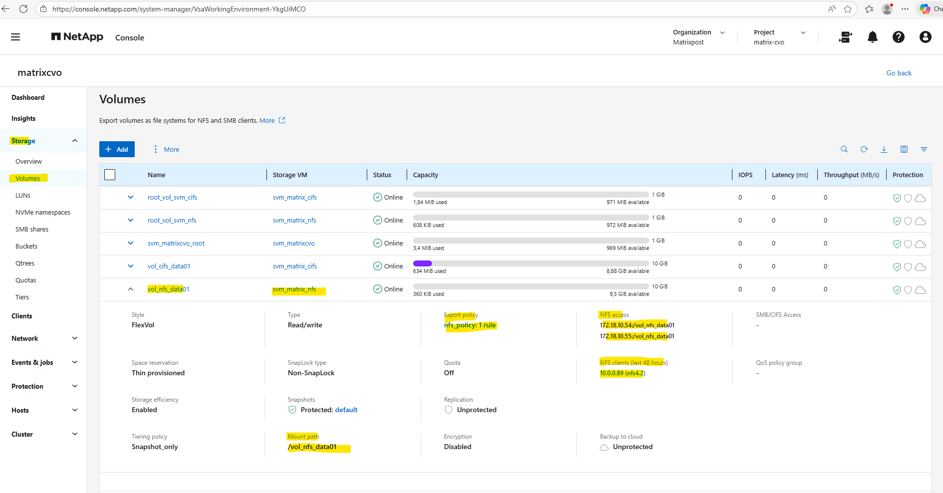
By using the Web UI we can now also see our newly created NFS export.
We can also see here the NFS clients connected the past 48 hours to this NFS export.
More about the NFS protocol you will find in my following post.
Creating Qtrees
In NetApp ONTAP, a qtree (quota tree) is a logically defined subdirectory within a volume that allows you to apply quotas and manage capacity at a finer level than the volume itself.
Think of a qtree as a container inside a volume that can be individually limited, monitored, and controlled, while still sharing the same volume-level properties (snapshots, efficiency, replication, etc.).
More about you will also find here https://blog.matrixpost.net/cheat-sheet-netapp-ontap-commands-used-in-day-to-day-operations/#qtrees.
A qtree must always exist before it can be exported or shared, and quotas should be defined before production use to avoid unexpected capacity issues.
The recommended sequence is:
- Create the volume and mount it in the namespace
- Create the qtree inside the volume
- Configure and initialize quotas (if required)
- Create the NFS export or CIFS share pointing to the qtree path
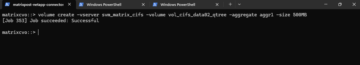
Below we will first create a 500MB data volume called vol_cifs_data02_qtree on aggr1.
matrixcvo::> volume create -vserver svm_matrix_cifs -volume vol_cifs_data02_qtree -aggregate aggr1 -size 500MB
After creating a volume, it must be mounted into the SVM namespace before it can be accessed by NFS or CIFS clients.
Mounting a volume defines its junction path, which determines where the volume appears in the filesystem hierarchy.
Without this step, the volume exists but cannot be exported (NFS) or shared (CIFS) in NetApp ONTAP.
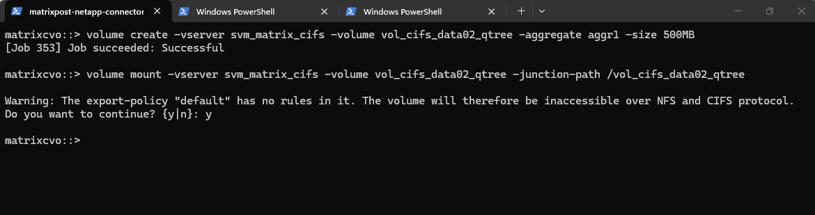
This command mounts the volume
vol_cifs_data02_qtreeinto the SVM namespace at the path/vol_cifs_data02_qtree, making it accessible to clients.You can safely ignore the warning about an empty export policy if the volume is intended exclusively for CIFS/SMB access. Because export policies are natively designed for NFS, they do not restrict Windows users, who are instead governed by Share permissions and NTFS ACLs.
matrixcvo::> volume mount -vserver svm_matrix_cifs -volume vol_cifs_data02_qtree -junction-path /vol_cifs_data02_qtree
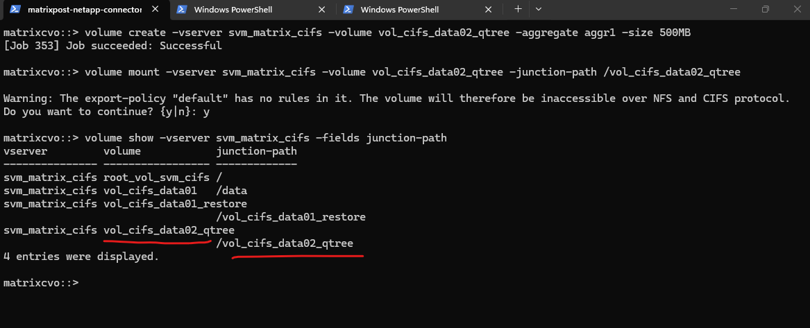
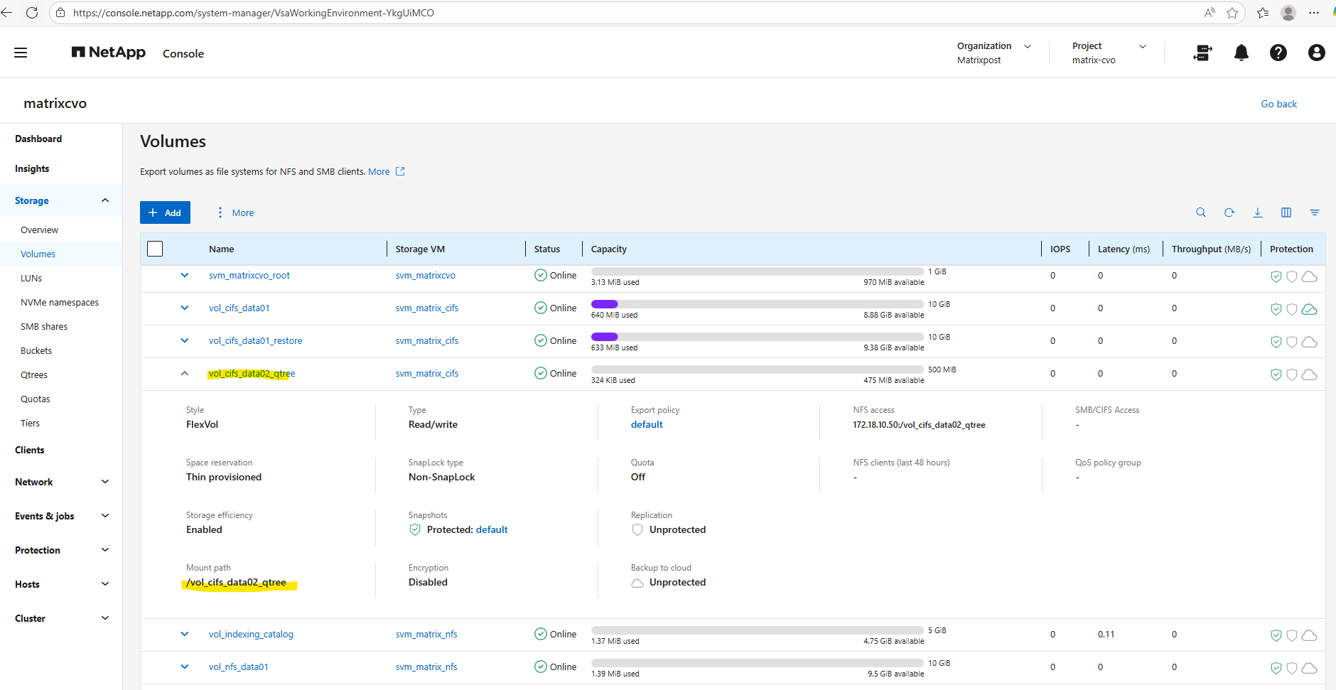
Checking the mount
matrixcvo::> volume show -vserver svm_matrix_cifs -fields junction-path
Now we can create a new qtree and quota on our newly created volume by running:
matrixcvo::> volume qtree create -vserver svm_matrix_cifs -volume vol_cifs_data02_qtree -qtree it-infra-team

# verify
matrixcvo::> qtree show
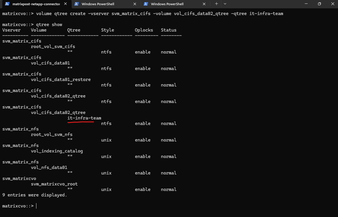
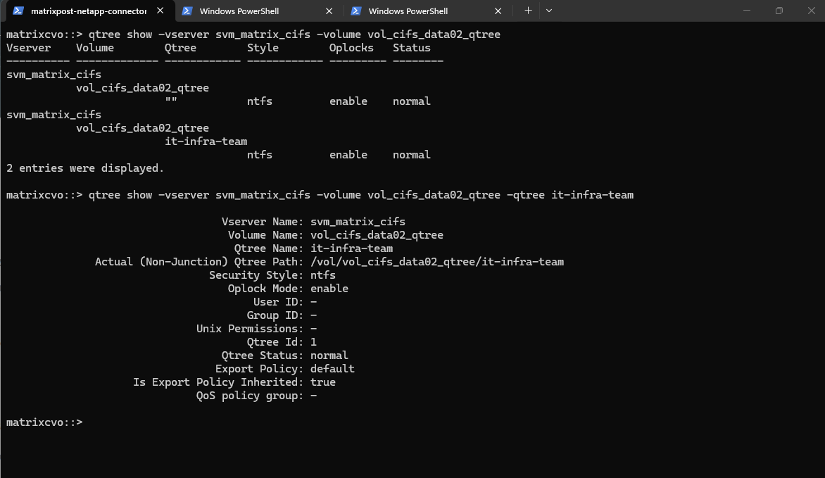
# list all qtrees for a specific volume
matrixcvo::> qtree show -vserver svm_matrix_cifs -volume vol_cifs_data02_qtree

# list a specific qtree
matrixcvo::> qtree show -vserver svm_matrix_cifs -volume vol_cifs_data02_qtree -qtree it-infra-team
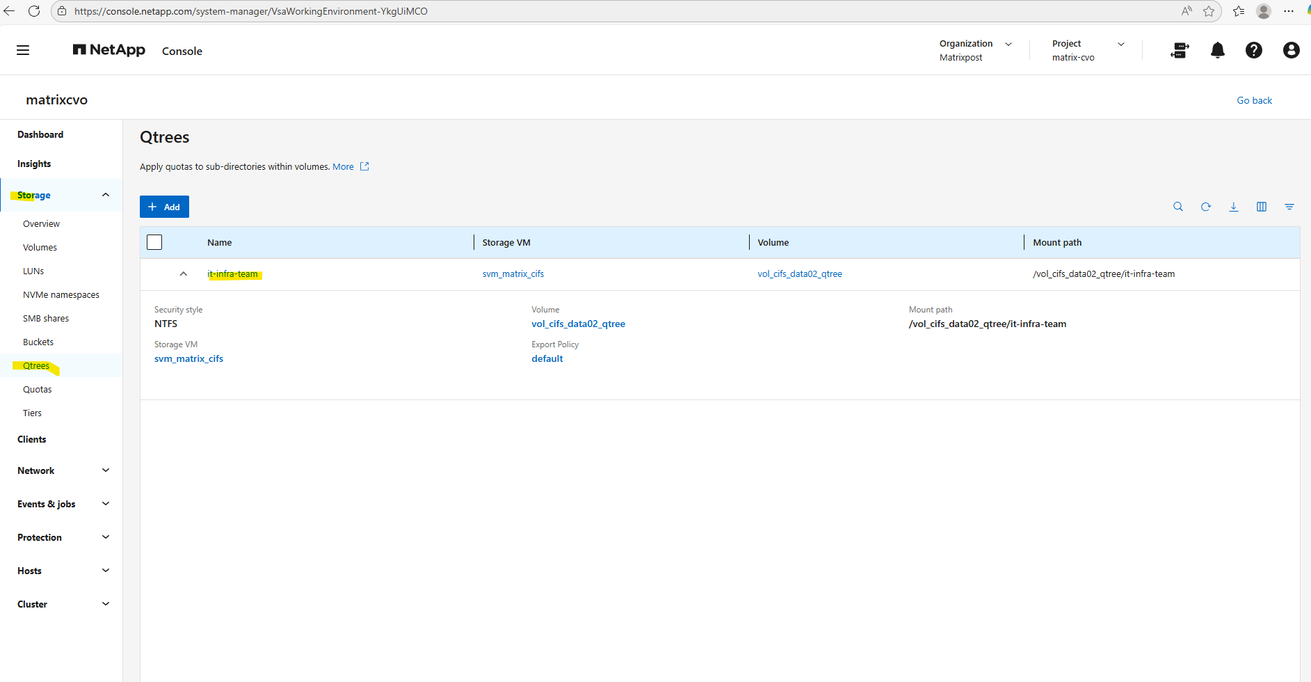
Check the qtree by using the WebGUI under Storage -> Qtrees.
We can now create a new qtree (tree) quota rule on our volume where we previously created the qtree.
This command creates a tree quota that limits the qtree
it-infra-teamto 100 MB within the volumevol_cifs_data02_qtree. For tree quotas, ONTAP identifies the quota only by the target name, which must match the qtree name, while the-qtreeparameter is ignored and therefore shown as"". As a result, specifying-qtree ""or-qtree it-infra-teammakes no functional difference for tree quotas in NetApp ONTAP.A qtree is a real filesystem object inside a volume that defines a distinct subtree where data is stored. The target is a quota-engine reference that tells ONTAP which qtree (or user/group) a quota rule applies to, linking quota enforcement to that object in NetApp ONTAP.
matrixcvo::> volume quota policy rule create -vserver svm_matrix_cifs -volume vol_cifs_data02_qtree -policy-name default -qtree "" -target it-infra-team -type tree -disk-limit 100MB
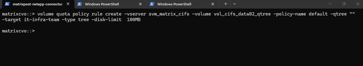
We must run quota resize (if quotas are already enabled on the volume).
Actually in my case so far I haven’t enabled quotas on the volume and could skip this here.
If quotas are already ON, ONTAP does not automatically re-scan the volume when a new qtree appears.
matrixcvo::> quota resize -vserver svm_matrix_cifs -volume vol_cifs_data02_qtree
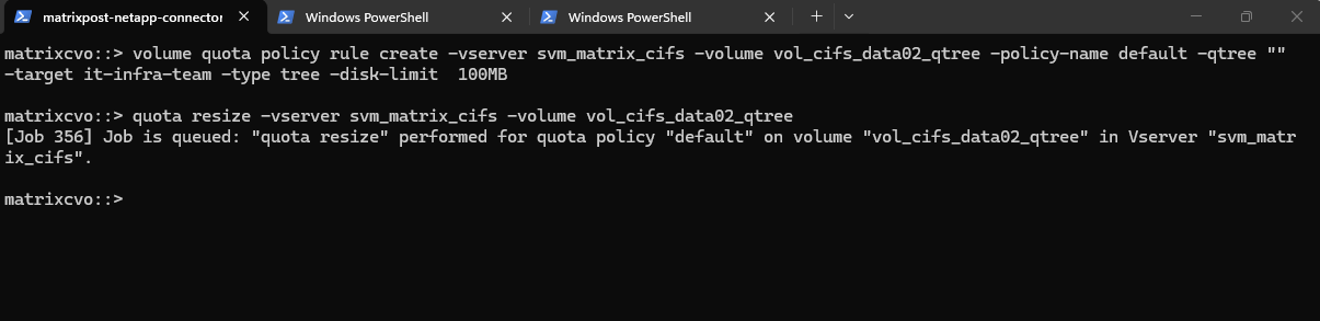
Quotas are not active until you explicitly enable them on the volume.
This command creates a job to activate quotas for the specified volume.
matrixcvo::> volume quota on -vserver svm_matrix_cifs -volume vol_cifs_data02_qtree
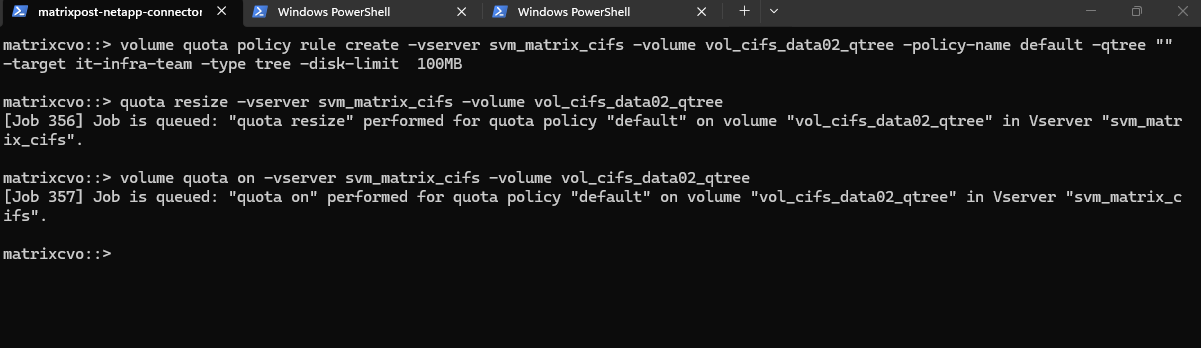
After enabling quotas on the volume we can see it also in the WebGUI under Storage -> Quotas as shown below.
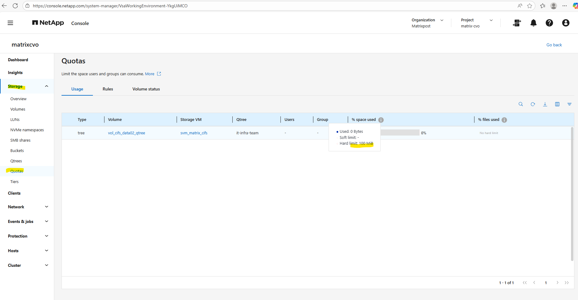
We can check the enabled quota(s) for a specific volume under Volumes -> Volume -> Quota Reports as shown below.
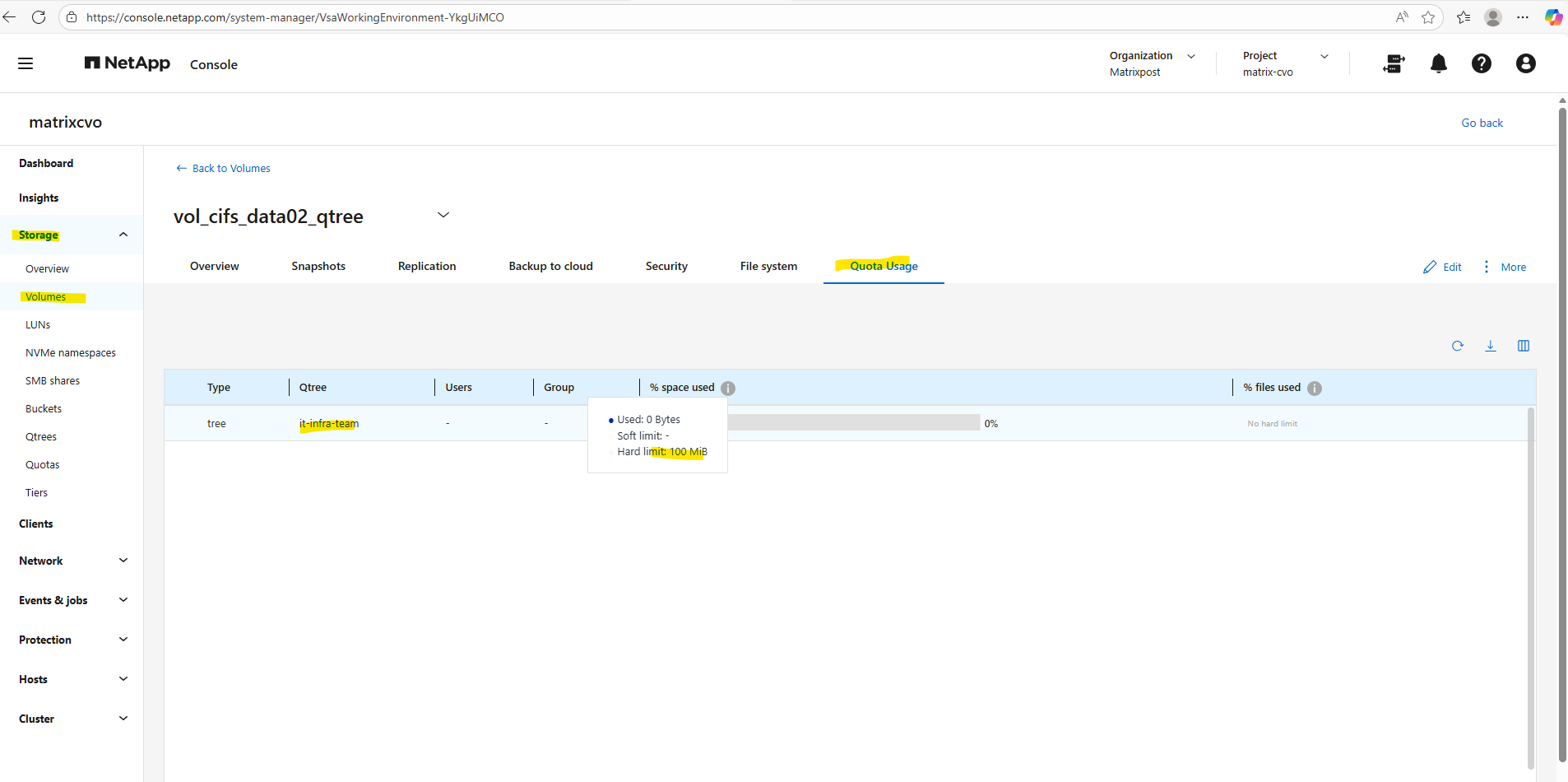
Or by using the CLI and the following command.
This command displays all quota policy rules applied to the volume
vol_cifs_data02_qtreeon the SVMsvm_matrix_cifs, including tree, user, and group quotas.It is typically used to verify which limits are configured and how they are scoped before or after initializing quotas in NetApp ONTAP.
matrixcvo::> volume quota policy rule show -vserver svm_matrix_cifs -volume vol_cifs_data02_qtree
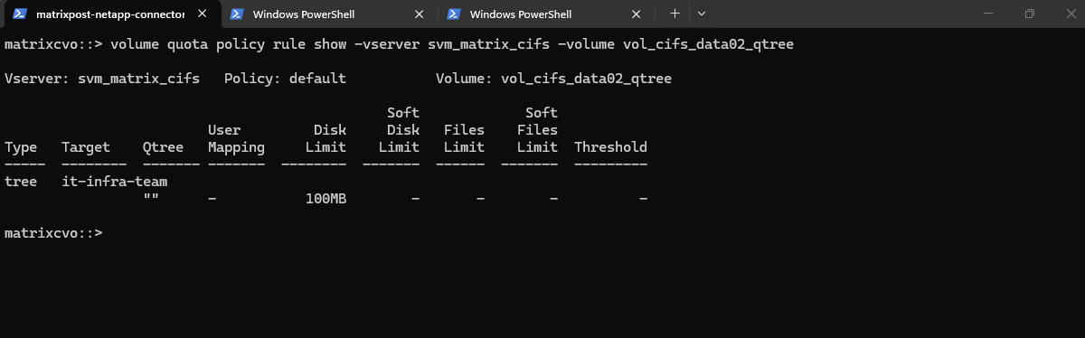
Finally we need to create the CIFS Share and pointing it to our newly created qtree by specifying the -path flag with the junction path of the volume plus the qtree name like shown below.
When you create that qtree, it will inherit the Security Style of the parent volume (likely NTFS if it’s a CIFS SVM).
The best practice is to make the Share Name and the Qtree Name the same.
If you ever need to change it specifically for that qtree without affecting the rest of the volume, you can do so with:
qtree modify -vserver svm_matrix_cifs -volume vol_cifs_data02_qtree -qtree it-infra-team -security-style ntfs
matrixcvo::> vserver cifs share create -vserver svm_matrix_cifs -share-name it-infra-team -path /vol_cifs_data02_qtree/it-infra-team
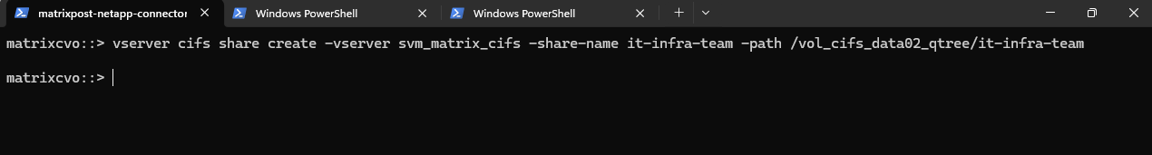
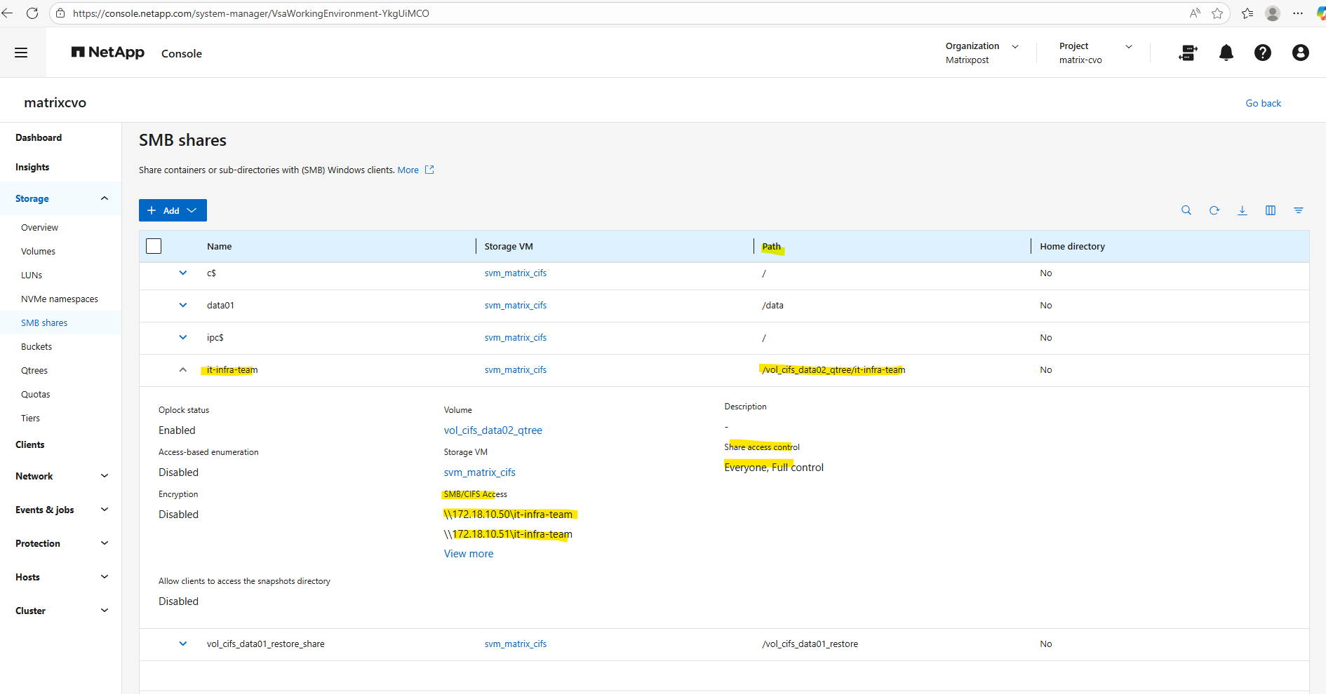
Using a single qtree per volume usually defeats the purpose of the feature, as it adds a layer of management complexity without providing any benefits over simply sharing the volume’s root.
Qtrees are designed to act as high-efficiency “virtual partitions,” allowing you to consolidate multiple departmental datasets into one manageable volume while still maintaining granular control over quotas and security styles.
If you only need one container per volume, you are better off skipping qtrees entirely and applying your settings directly to the volume level.
To see the ‘Multi-Qtree’ model in action and prove how easily we can silo data within a single volume, I’m going to spin up a second Qtree and CIFS Share for the Accounting team.
# Create the Qtree
vserver cifs share create -vserver svm_matrix_cifs -share-name accounting_data -path /vol_cifs_data02_qtree/accounting-team

# Create the Share
matrixcvo::> vserver cifs share create -vserver svm_matrix_cifs -share-name accounting_data -path /vol_cifs_data02_qtree/accounting-team
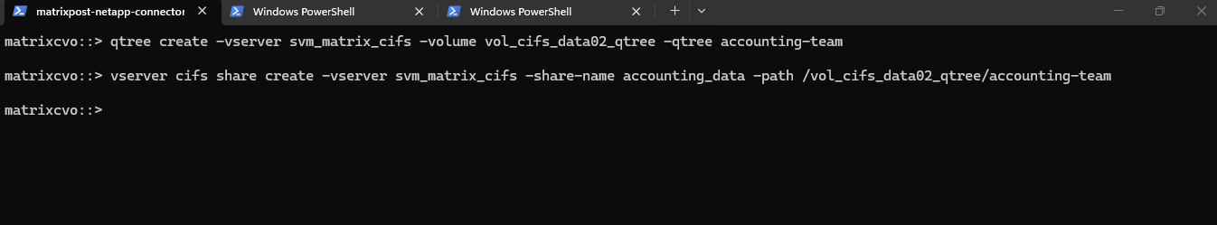
Create a new qtree (tree) quota rule.
matrixcvo::> volume quota policy rule create -vserver svm_matrix_cifs -volume vol_cifs_data02_qtree -policy-name default -qtree "" -target accounting-team -type tree -disk-limit 100MB
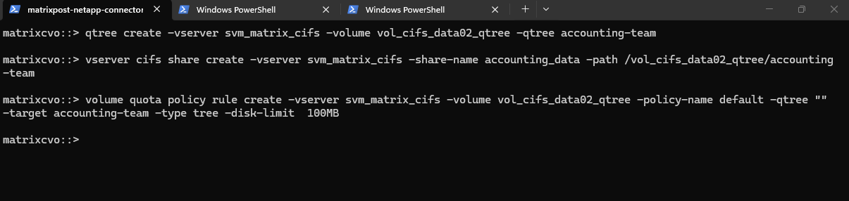
The mount path we can determine either by using the ONTAP System Manager as shown below or the ONTAP CLI.
By using the System Manager we need to navigate to Storage -> SMB shares (or Volumes for NFS exports). Here we will see the mount path within SMB/CIFS Access resp. NFS access.
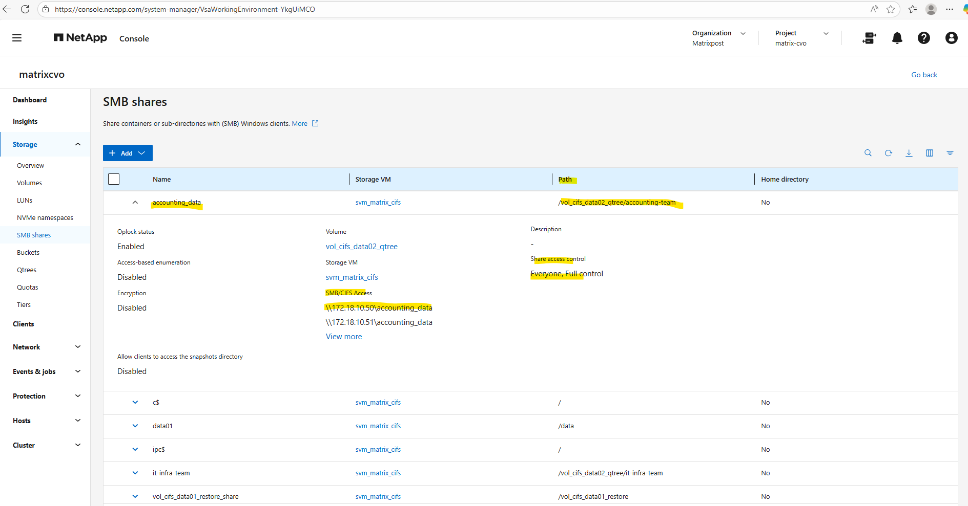
With the configuration complete, we can now map these Qtrees as network drives on our Windows clients using their respective CIFS share names.
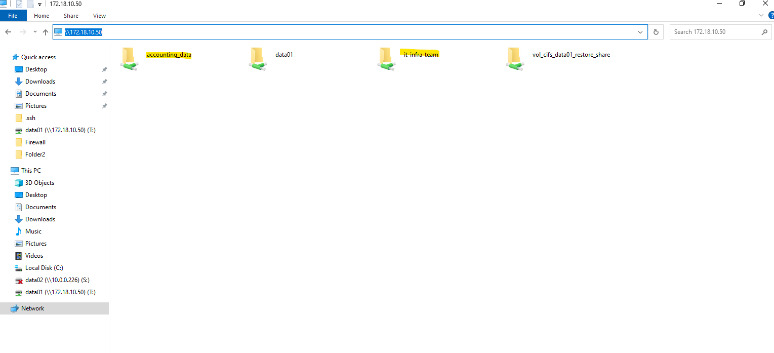
We can also use the ONTAP CLI as mentioned to obtain the mount path.
Finally we need to know the junction path of the volume to obtain the junction path or namespace path of the qtree.
matrixcvo::> volume show -volume vol_cifs_data02_qtree -vserver svm_matrix_cifs -fields junction-path
matrixcvo::> qtree show -vserver svm_matrix_cifs -volume vol_cifs_data02_qtree
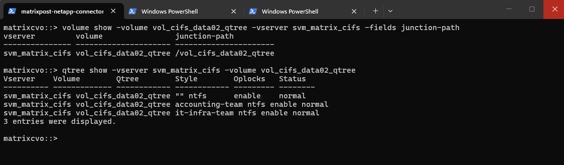
Since qtrees are always rooted at the volume, the junction path or namespace path of the qtree will be in my case /vol_cifs_data02_qtree/it-infra-team and /vol_cifs_data02_qtree/accounting-team.
In case this would be an NFS export, we can mount the qtree by running:
SLES15-SP5-Testing01:/ # mount -t nfs -o rw 172.18.10.50:/vol_cifs_data02_qtree/it-infra-team /qtree/

and

SLES15-SP5-Testing01:/ # mount -t nfs -o rw 172.18.10.50:/vol_cifs_data02_qtree/accounting-team /qtree/
In case of CIFS/SMB shares we just need the FQDN or IP of the SVM and the qtree name for the UNC path like shown below.
\\172.18.10.50\it-infra-team
\\172.18.10.50\accounting_data
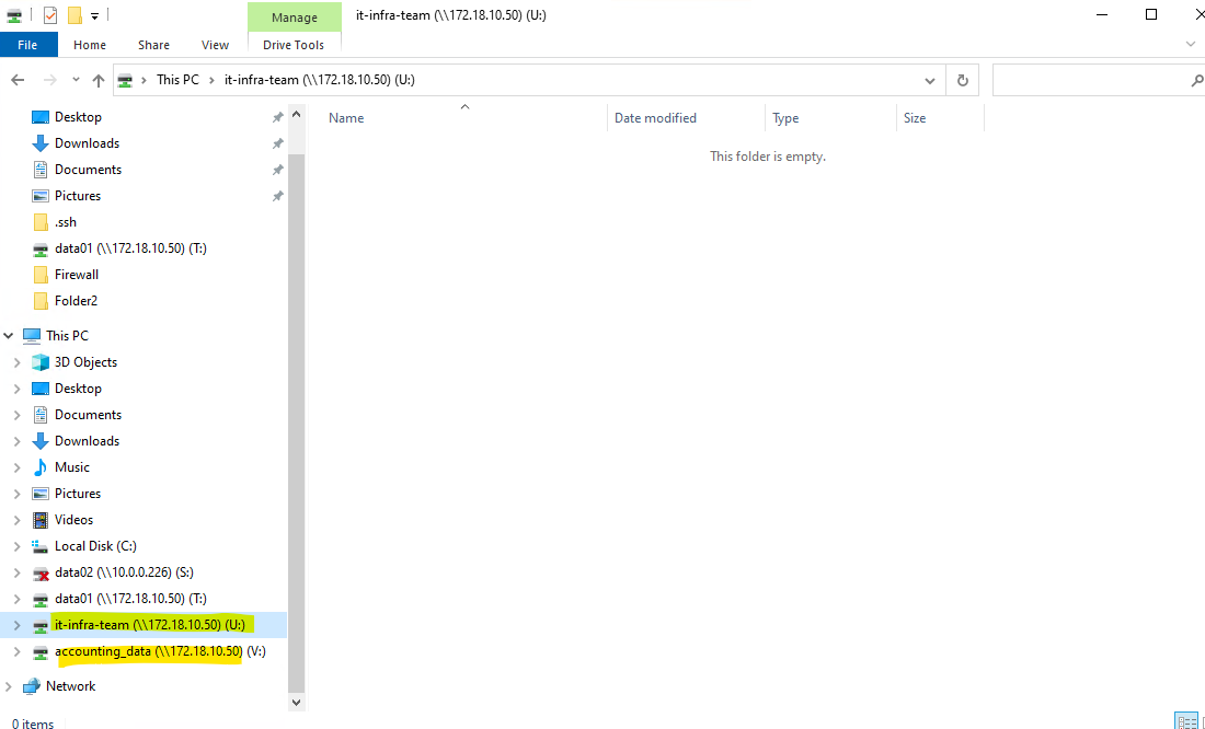
In an ONTAP environment, it is a standard best practice to set SMB share permissions to
Everyone / Full Controlto act as a “wide open” gate at the protocol level.By doing this, you avoid the administrative headache of clashing permissions and instead consolidate all granular security management within the NTFS ACLs on the files and folders themselves.
This “Pass-Through” share model ensures that the effective permissions a user experiences are determined solely by your Windows security groups, making troubleshooting significantly simpler.
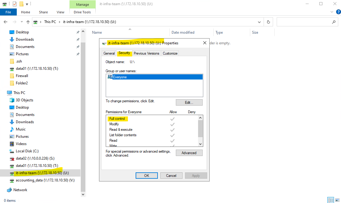
matrixcvo::> vserver cifs share access-control show -vserver svm_matrix_cifs -share it-infra-team
matrixcvo::> vserver cifs share access-control show -vserver svm_matrix_cifs -share accounting_data
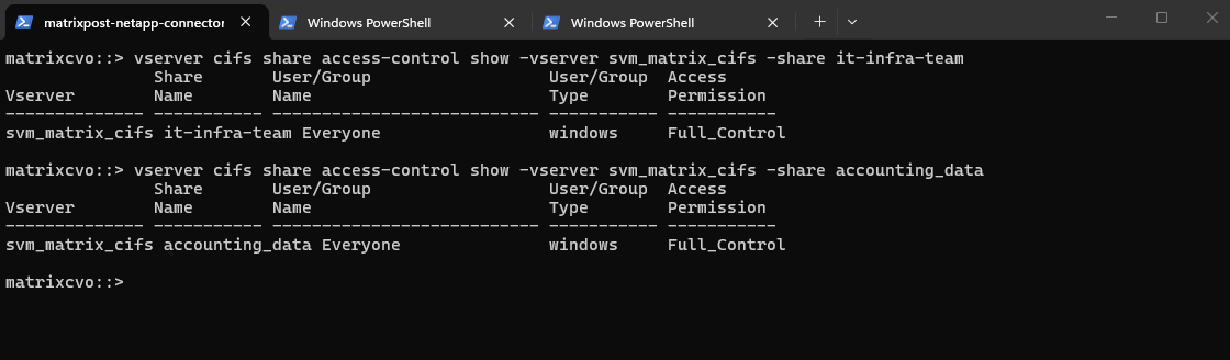
Creating Qtrees for NFS exports (volumes) is finally the same as mentioned.
Below, I create a dedicated NFS volume and define two qtrees within it.
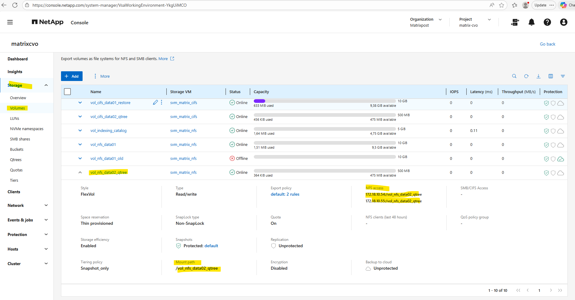
Within Storage -> Qtrees we will see both qtrees highliged I created for the dedicated NFS volume named vol_nfs_data02_qtree.
We can also obtain the Linux mount path for each qtree defined on the NFS volume below, finally always <FQDN/IP SVM>:/<volume>/<qtree target name>.
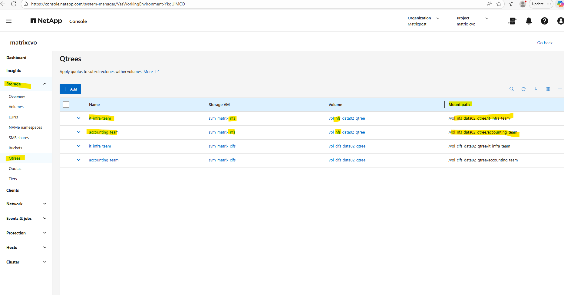
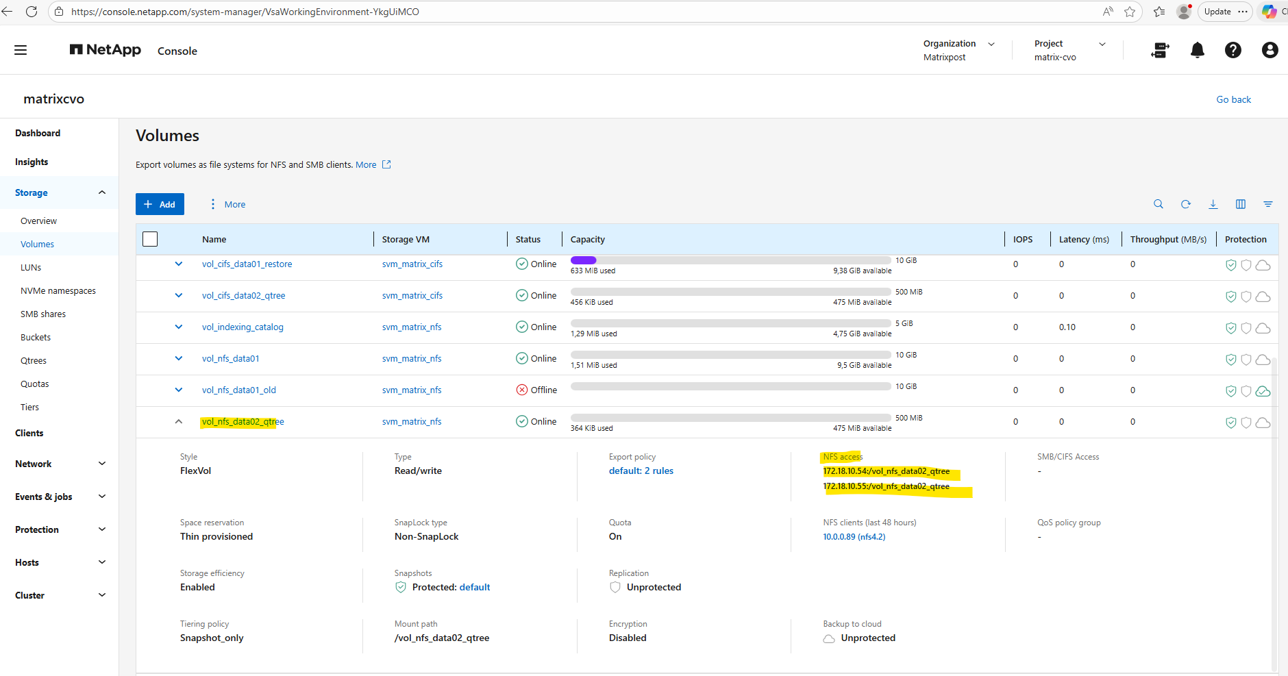
# mount -t nfs -o rw 172.18.10.54:/vol_nfs_data02_qtree/it-infra-team /it-infra-team/
# mount -t nfs -o rw 172.18.10.54:/vol_nfs_data02_qtree/accounting-team /accounting-team/
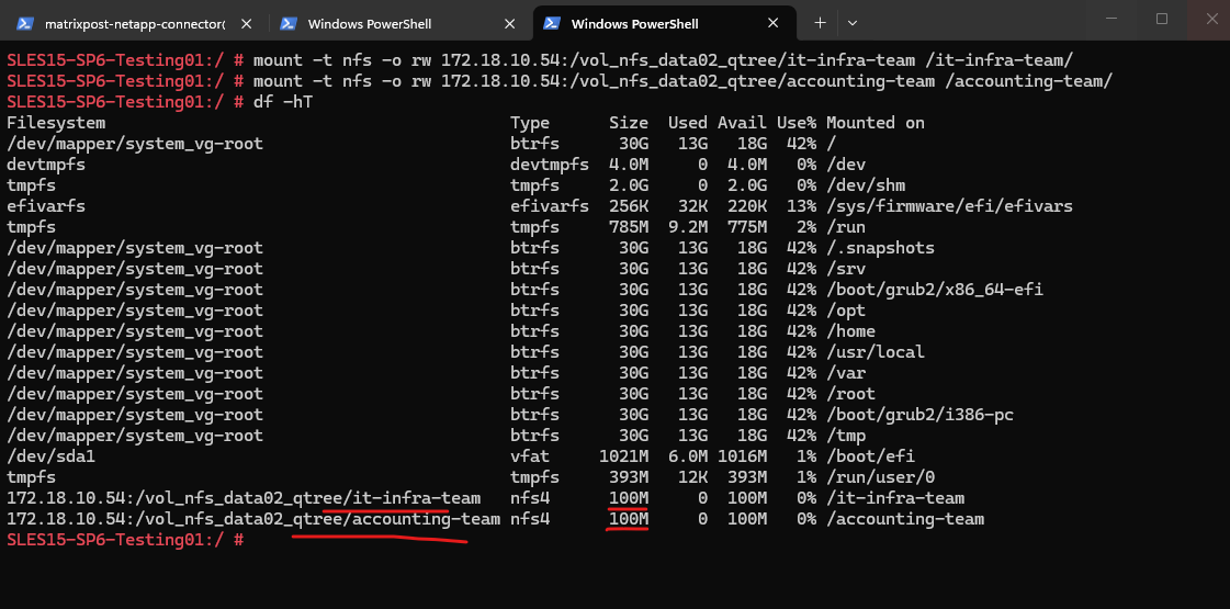
More about Qtrees including resizing quota you will also find here https://blog.matrixpost.net/cheat-sheet-netapp-ontap-commands-used-in-day-to-day-operations/#qtrees.
VNet Peering and Site-to-Site VPN Connectivity to the On-Prem Network
In this section, I’ll show how the CVO virtual network is peered with an existing hub VNet, which is already connected to my on-premises environment via a site-to-site IPsec VPN.
This setup allows seamless connectivity between Azure and the on-prem vSphere lab, enabling direct access to CVO services from on-prem systems without exposing them publicly.
On the hub VNet I will add a new peering as shown below.
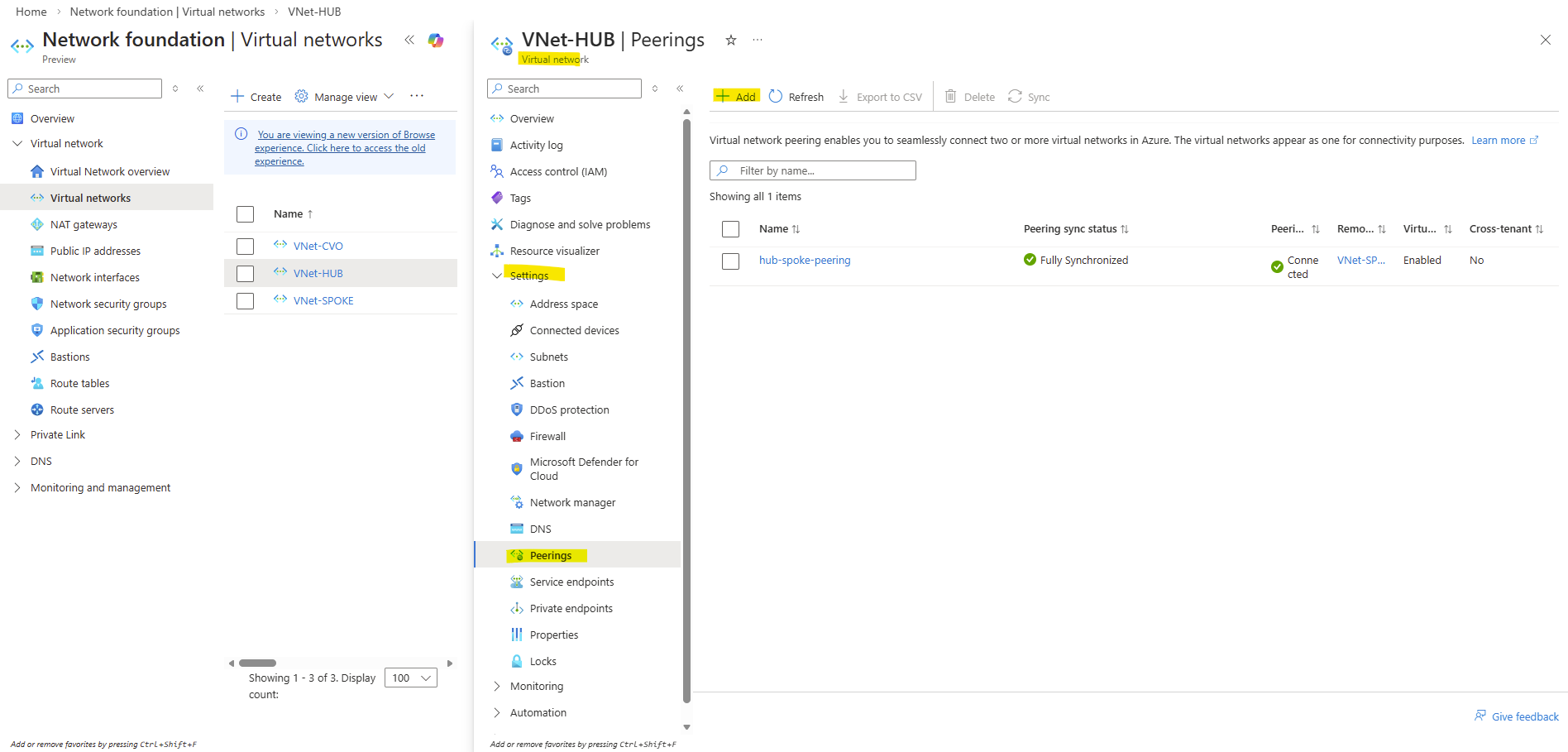
For the remote virtual network select our dedicated CVO virtual network and check Allow ‘VNet-HUB’ to access ‘VNet-CVO’ and Allow ‘VNet-HUB’ to receive forwarded traffic from ‘VNet-CVO’.
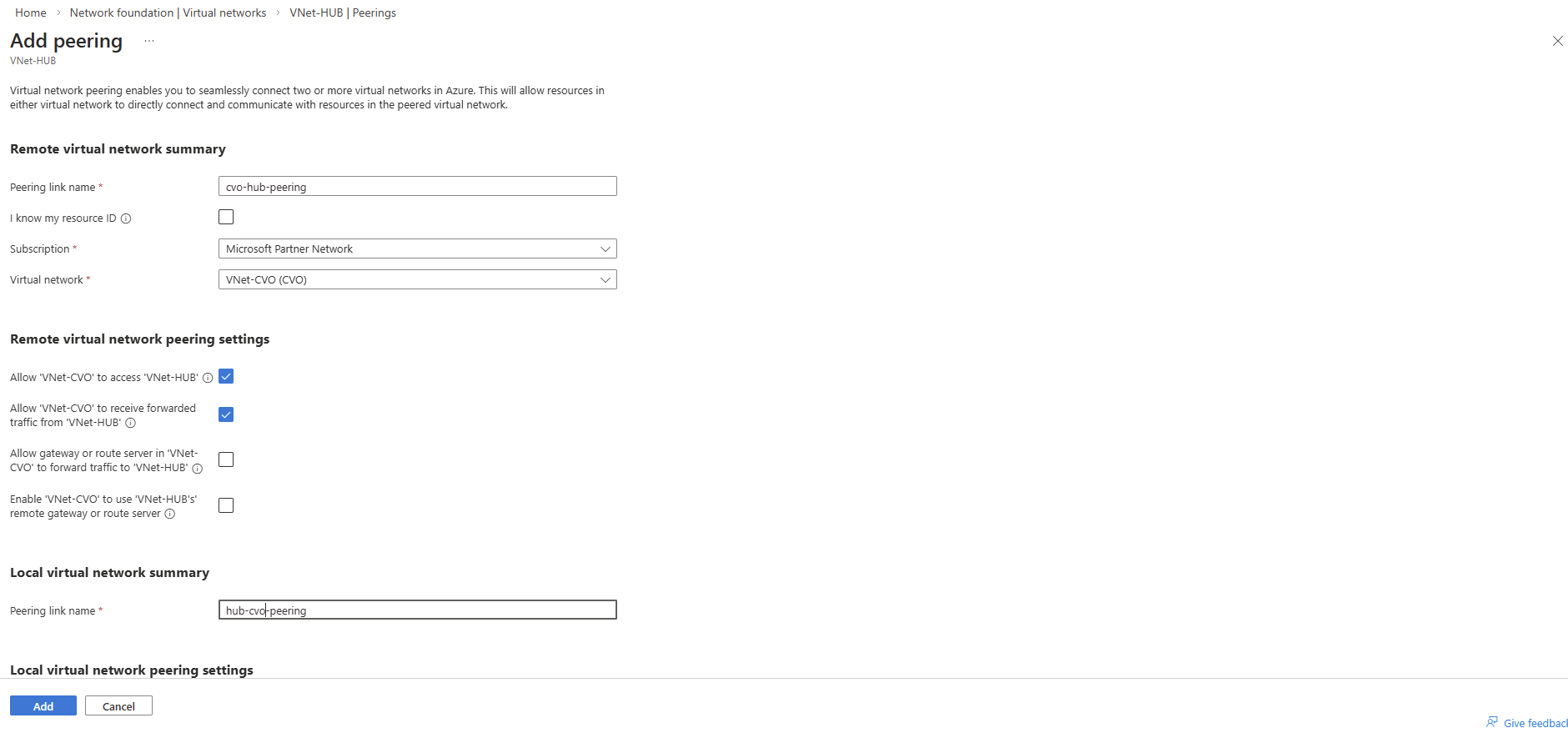
For the local virtual network check Allow ‘VNet-HUB’ to access ‘VNET-CVO’ and Allow ‘VNet-HUB’ to receive forwarded traffic from ‘VNet-CVO’.
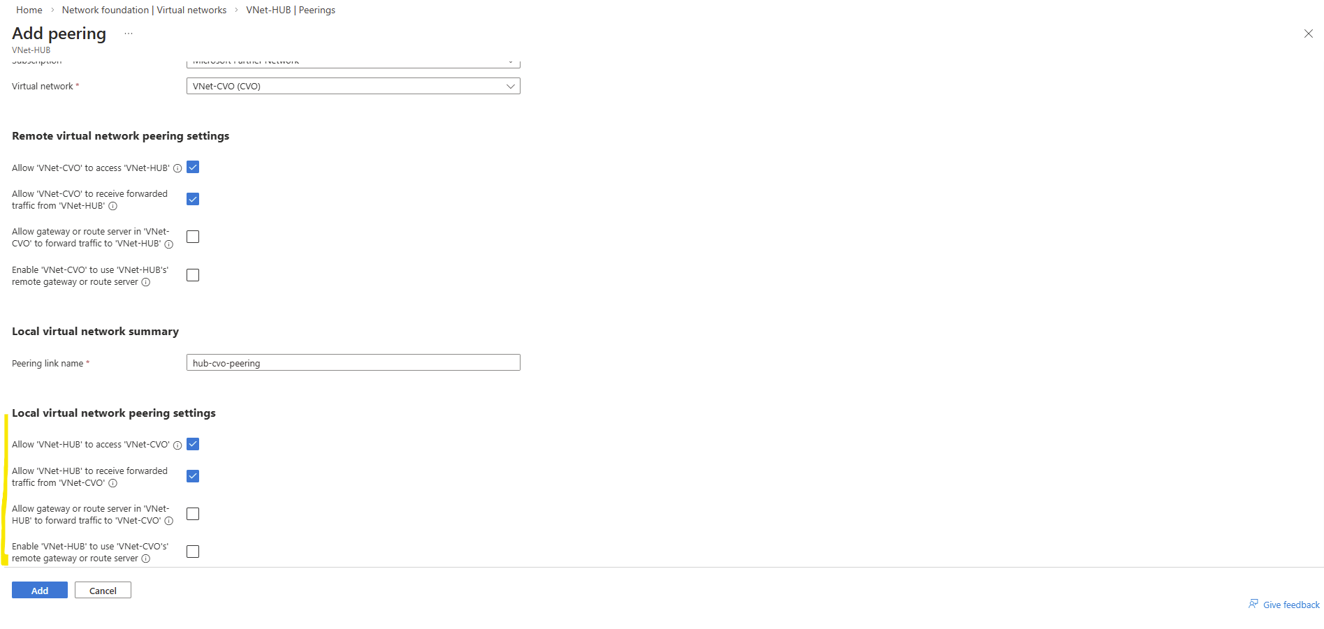
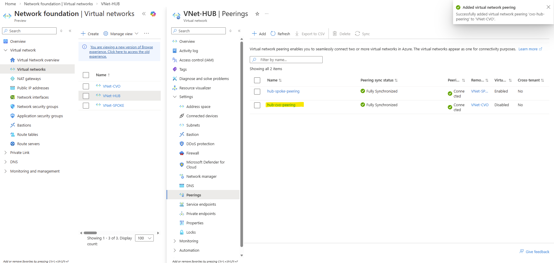
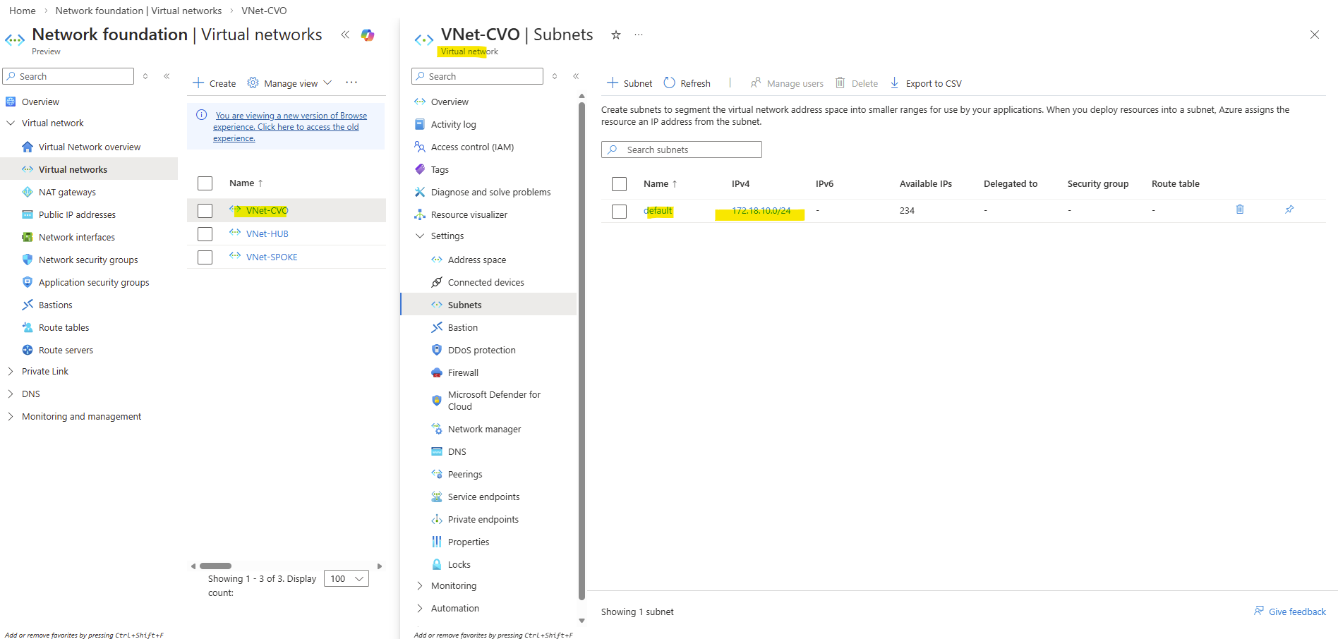
Configuring pfSense for Site-to-Site Connectivity (Azure & On-Prem)
In this section, I’ll cover the network configuration required when using pfSense instead of Azure’s native VPN Gateway for site-to-site connectivity.
About deploying pfSense in Azure you can also read my following post.
Since pfSense does not automatically handle route propagation like the Azure VPN Gateway, a few manual steps are required.
This includes adjusting the FRR BGP configuration in Azure to advertise the new CVO virtual network, updating the on-prem pfSense firewall rules to allow traffic from the CVO subnet, and adding static routes on the Azure pfSense instance so traffic can be forwarded correctly.
On the pfSense appliance running in Azure I will first add the Cloud Volume ONTAP virtual network subnet where the Agent (Connector VM) and both ONTAP nodes (VMs) are running.
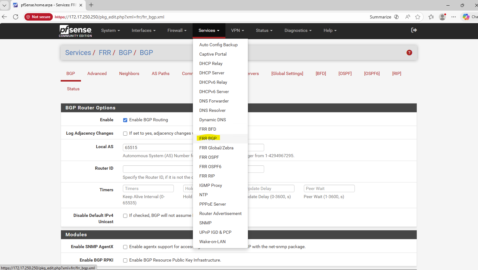
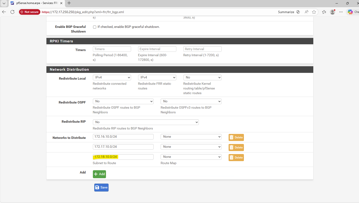
On my on-premise pfSense appliance I can see that the Cloud Volume ONTAP subnet is already successfully advertised to my on-prem environment and pfSense.
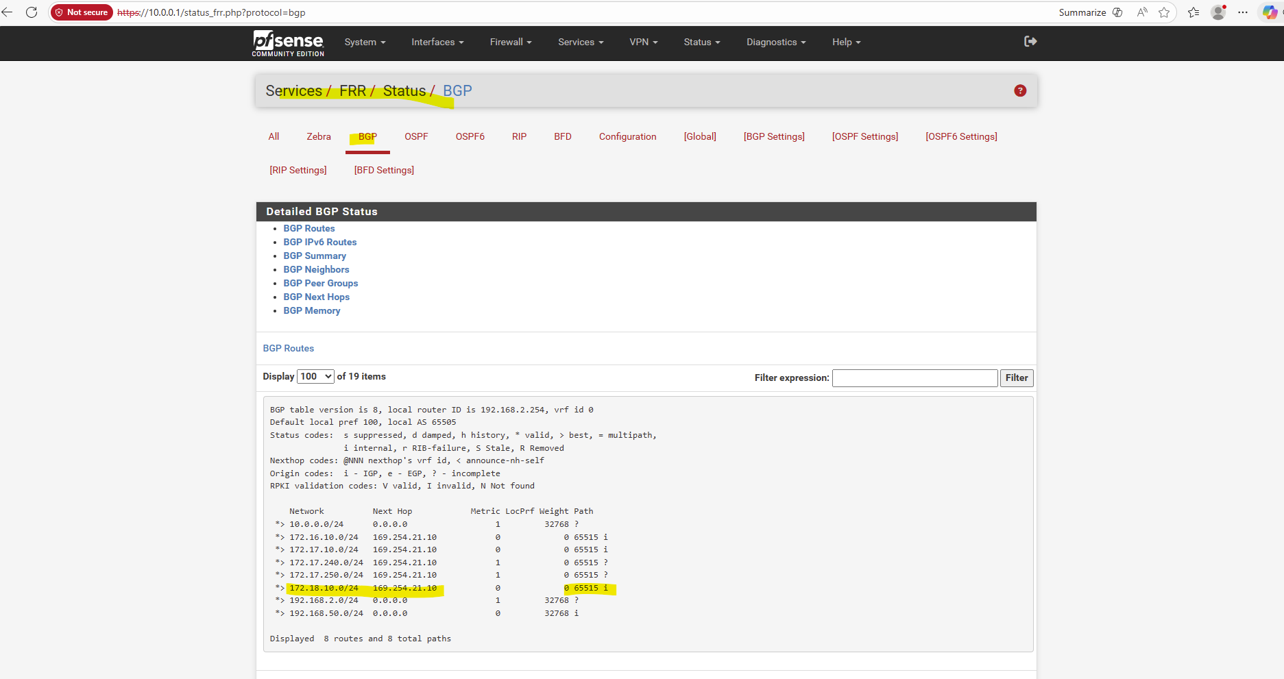
So I will test from an on-prem virtual machine running in my vSphere lab environment if I can connect to the Agent (Connector VM).
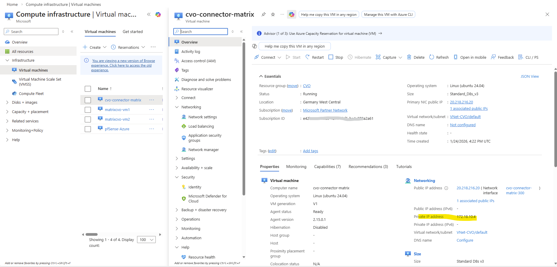
So far I can’t reach the Agent (Connector VM) from my on-prem environment.
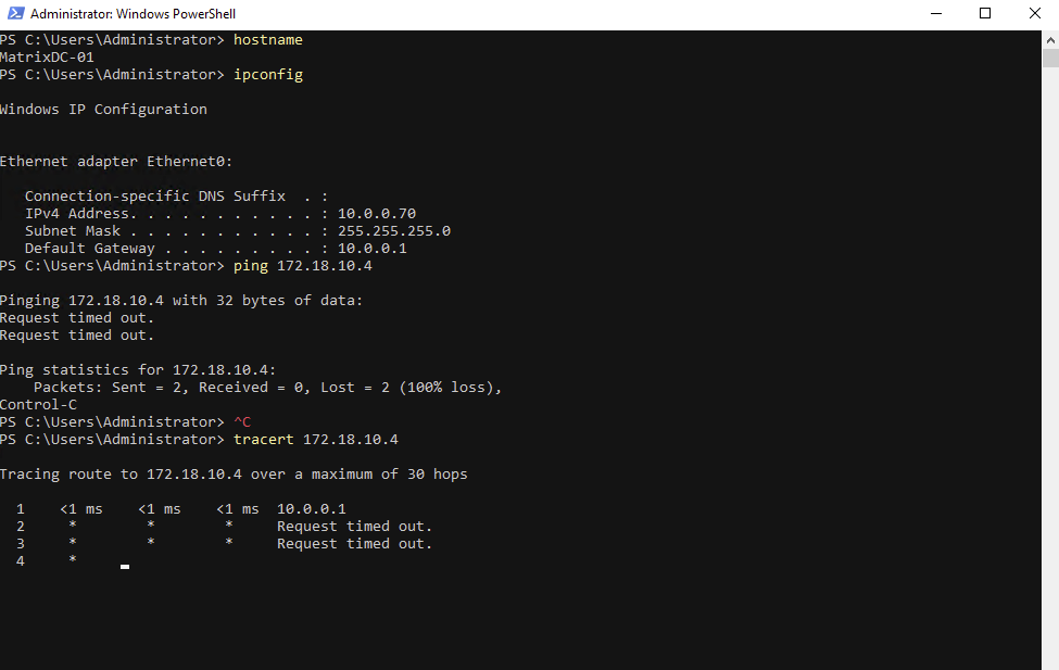
The attached NSG to the network interface of the connector VM will allow ICMP traffic already.
Although the on-prem network is external to Azure, traffic arriving via a site-to-site VPN is treated as VirtualNetwork traffic by Azure. This means it matches the default
AllowVNetInBoundNSG rule, which allows all protocols, including ICMP. As a result, ICMP traffic such as ping is permitted unless explicitly blocked by a custom NSG rule or firewall.
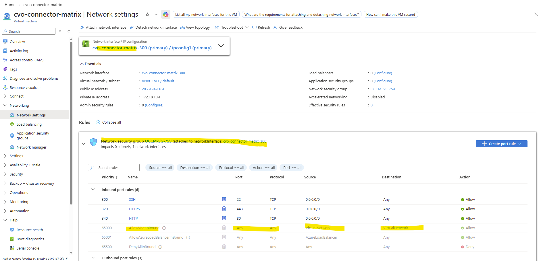
So next I will check if the Agent (Connector VM) has the route to my on-prem network 10.0.0.0/24, which is not the case and missing so far.
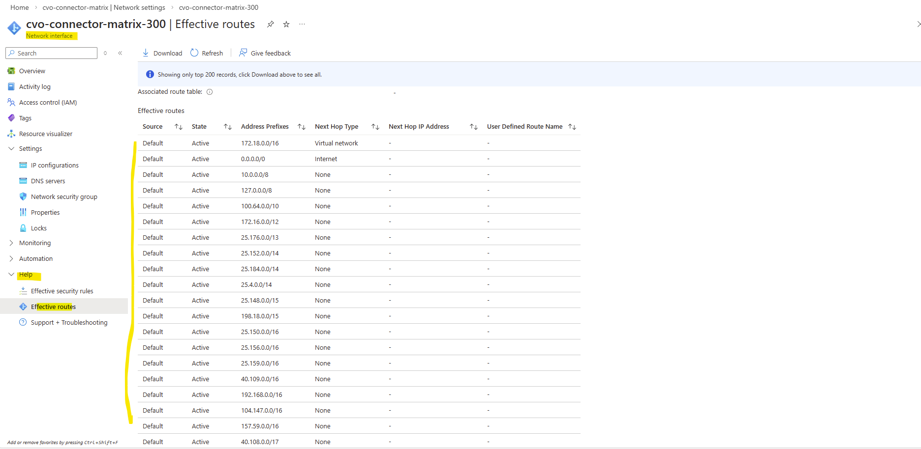
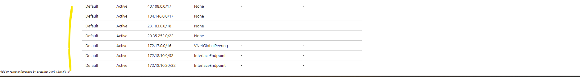
The pfSense appliance running in Azure have the following route table where also the on-prem network with 10.0.0.0/24 is listed.
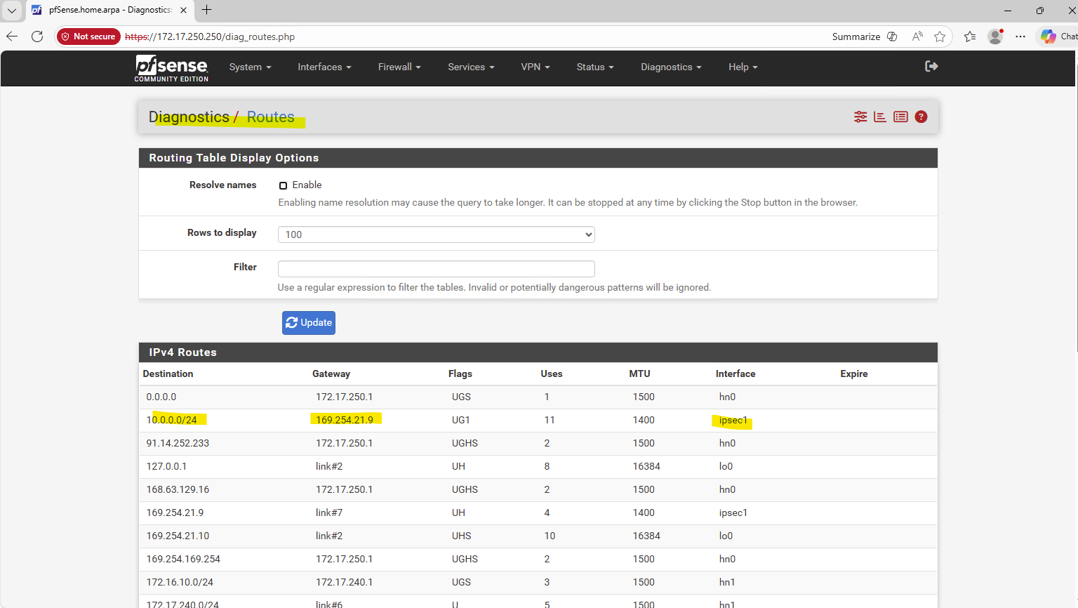
This route is advertised by the on-prem pfSense appliance to the pfSense appliance running in Azure by using BGP.
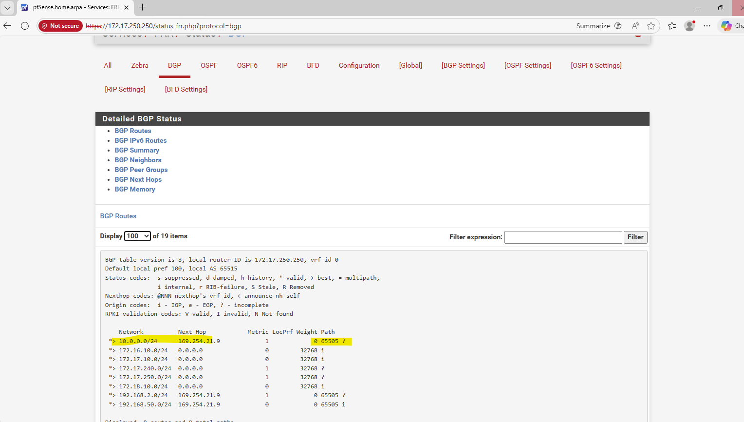
I will also allow all inbound traffic on the Azure pfSense from the CVO subnet 172.18.10.0/24.
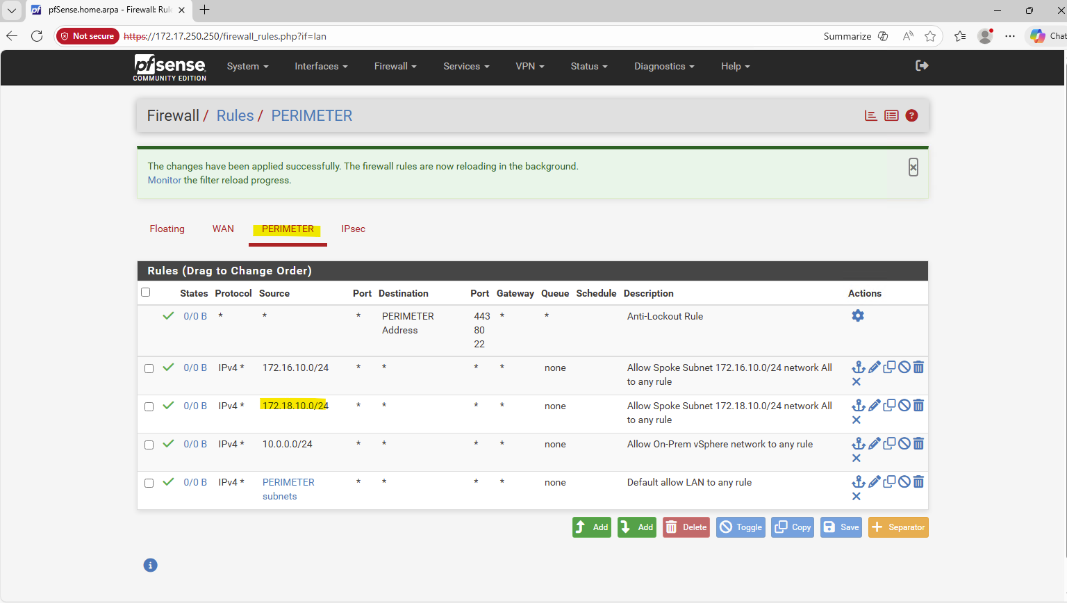
Nevertheless I can’t reach the pfSense appliance on its internal network interface with the IP 172.17.240.250 from the connector VM.
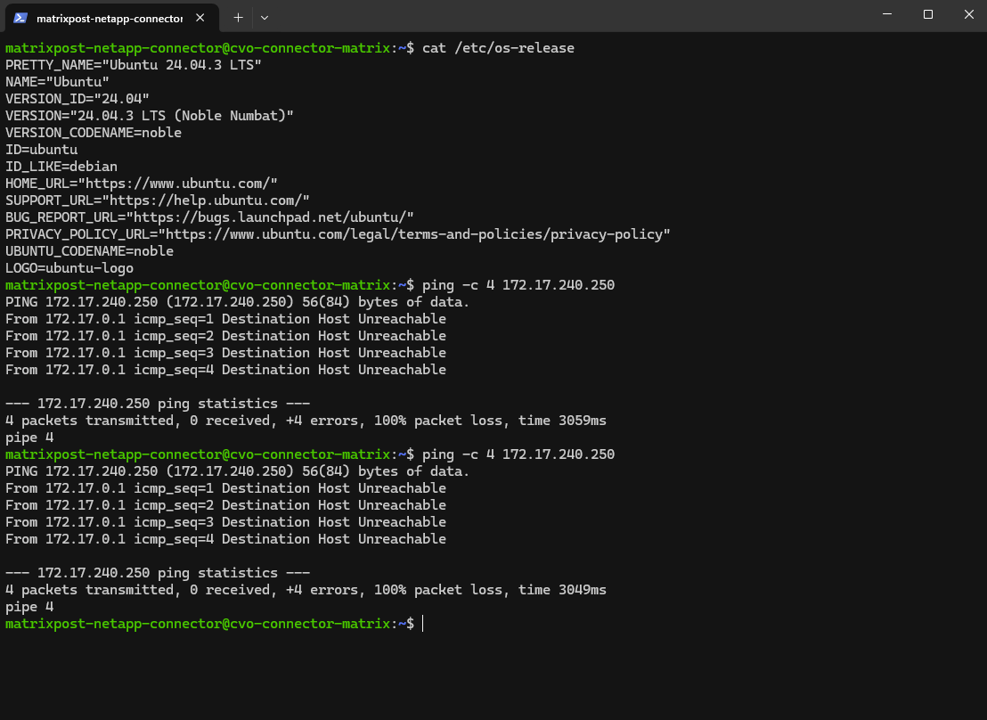
The Agent (Connector VM) has because of the VNet peering, already the route to the virtual network where the Azure pfSense appliance is running.
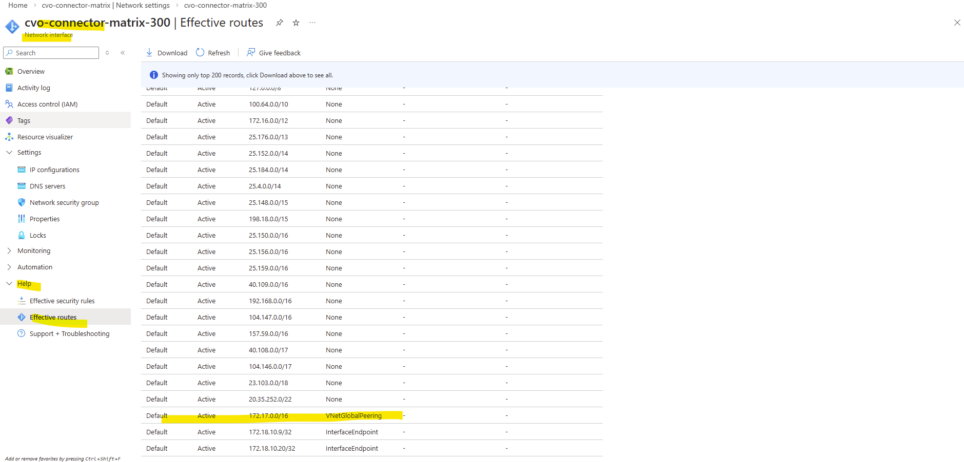
But the pfSense appliance in Azure so far doesn’t have a route to the virtual network for the CVO deployment with its subnet 172.18.10.0/24.
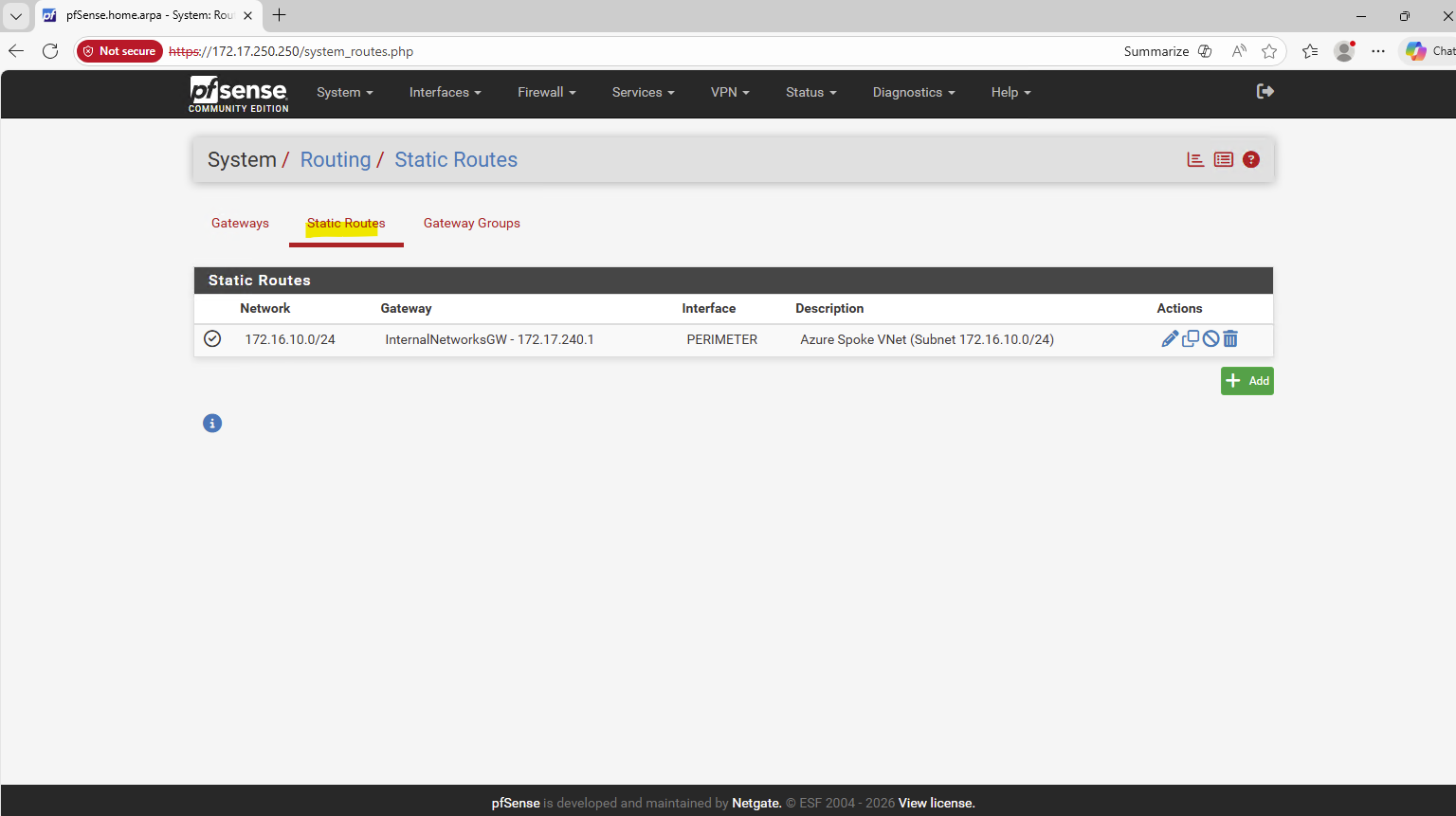
So I will add this route on the Azure pfSense appliance.
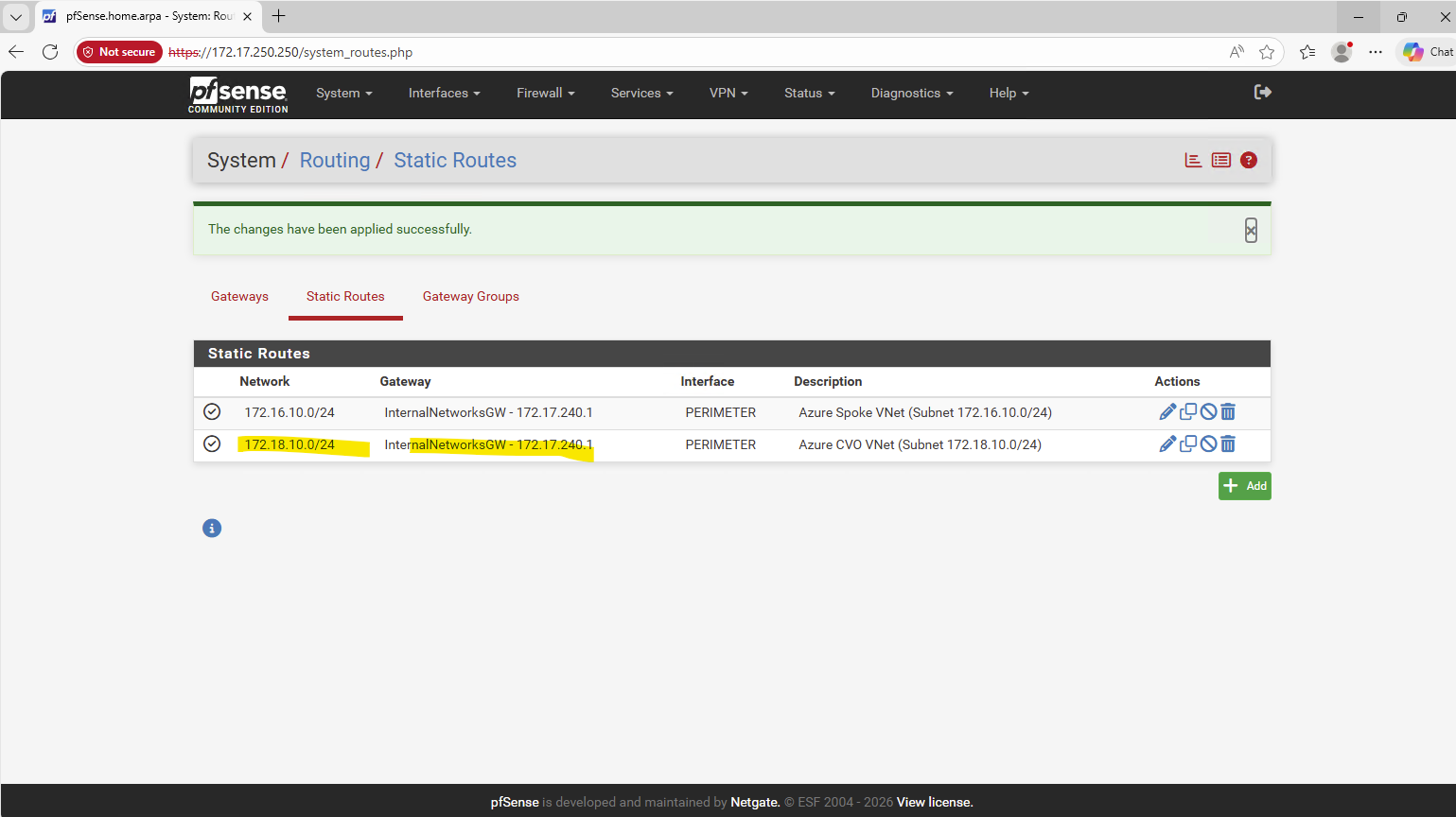
Unfortunately I still can’t ping Azure pfSense’s internal network interface and its IP address 172.17.240.250.
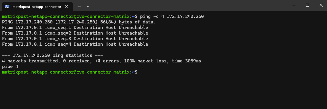
The reason for is that the route on the Agent (Connector VM) for the pfSense’s network interface and IP address 172.17.240.0/24 is missing.
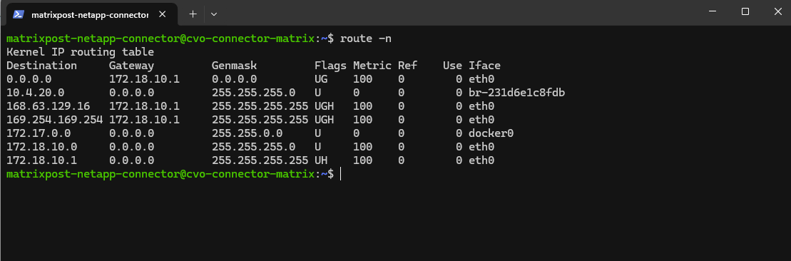
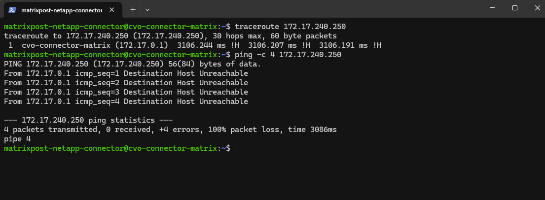
For testing purpose I will add the route manually and temporary on the connector VM.
In Azure, the first usable IP address of every subnet is always reserved as the default gateway, implemented by Azure’s software-defined router (SDN). This gateway is not a VM, not visible, and not configurable, it’s Azure’s internal routing fabric.
Reserved by Azure:
172.18.10.0→ network address,172.18.10.1→ Azure default gateway,172.18.10.2–3→ Azure internal use, Usable for VMs: starting at172.18.10.4
$ sudo ip route add 172.17.240.0/24 via 172.18.10.1 dev eth0
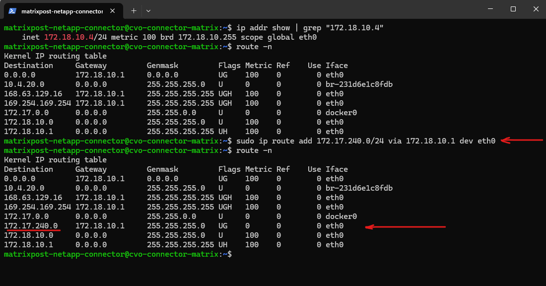
Testing if the Agent (Connector VM) can now ping the pfSense appliance running in Azure. Looks good now!
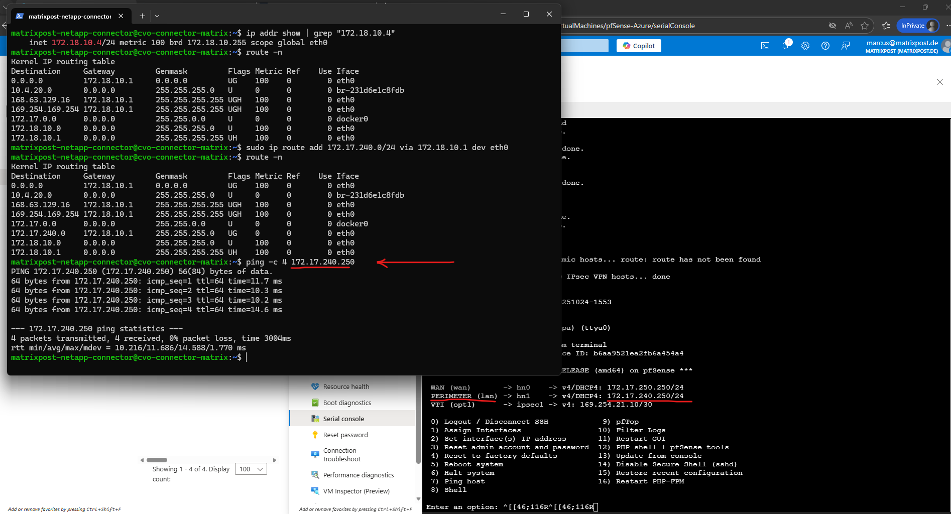
And vice versa testing if pfSense can ping the connector VM.
Looks also good.
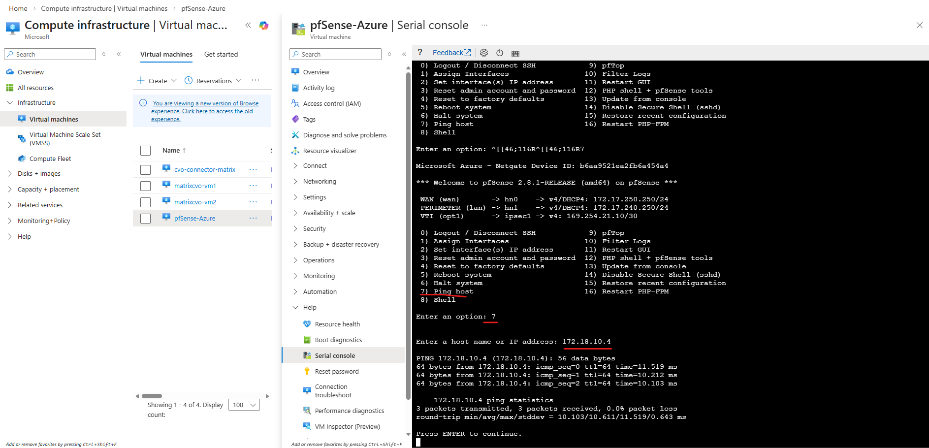
To provide these routes to all virtual machines without configuring them manually on each system in the CVO network, I will create a new route table, adding the required routes and associating it to the CVO subnet.
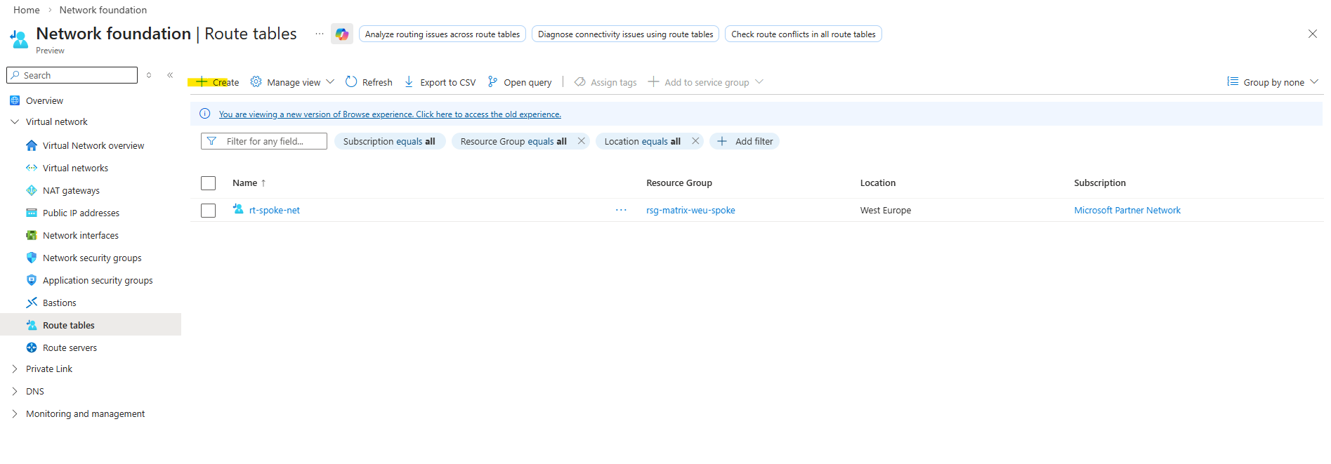
Propagate gateway routes in my case I can leave because I am not using the Azure VPN Gateway to connect my on-premise environment and instead using my pfSense appliance which will not advertise its routes by default to Azure’s internal routing fabric.
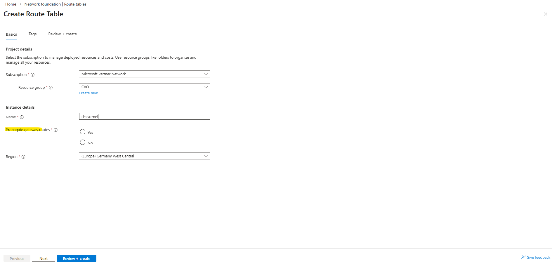
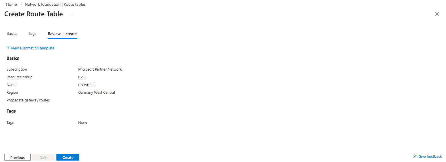
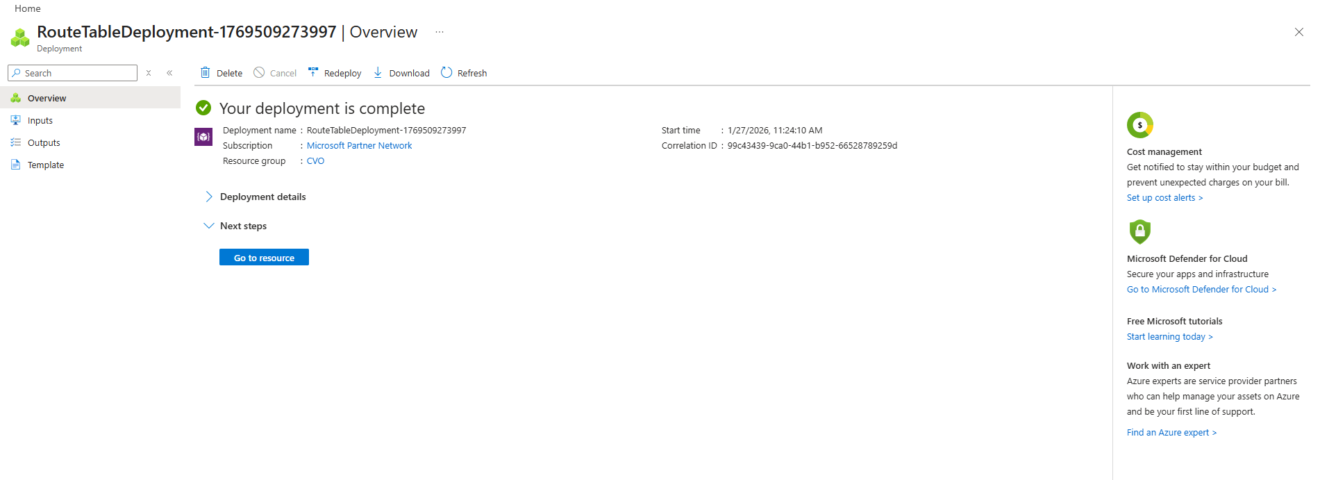
Adding a new route.
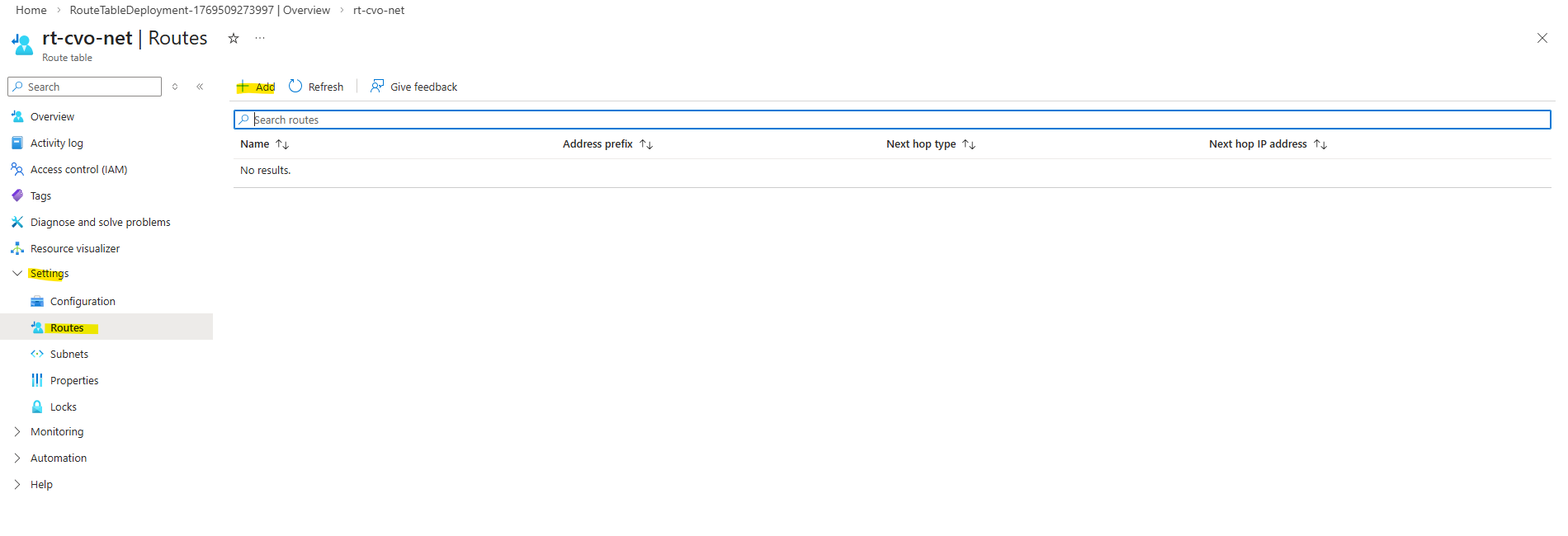
Below I will add a new route which shows the next hop (172.18.10.1 Azure default gateway) to route traffic to my hub virtual network resp. its perimeter subnet (172.17.240.0/24) in which my pfSense appliance (its internal network interface and IP 172.17.240.250) is running and establishing a site-to-site VPN tunnel with my on-prem network.
In Azure, thefirst usable IP address ofevery subnet is always reserved as the default gateway, implemented by Azure’s software-defined router (SDN). This gateway is not a VM, not visible, and not configurable, it’s Azure’s internal routing fabric.
Reserved by Azure:
172.18.10.0→ network address,172.18.10.1→ Azure default gateway,172.18.10.2–3→ Azure internal use, Usable for VMs: starting at172.18.10.4
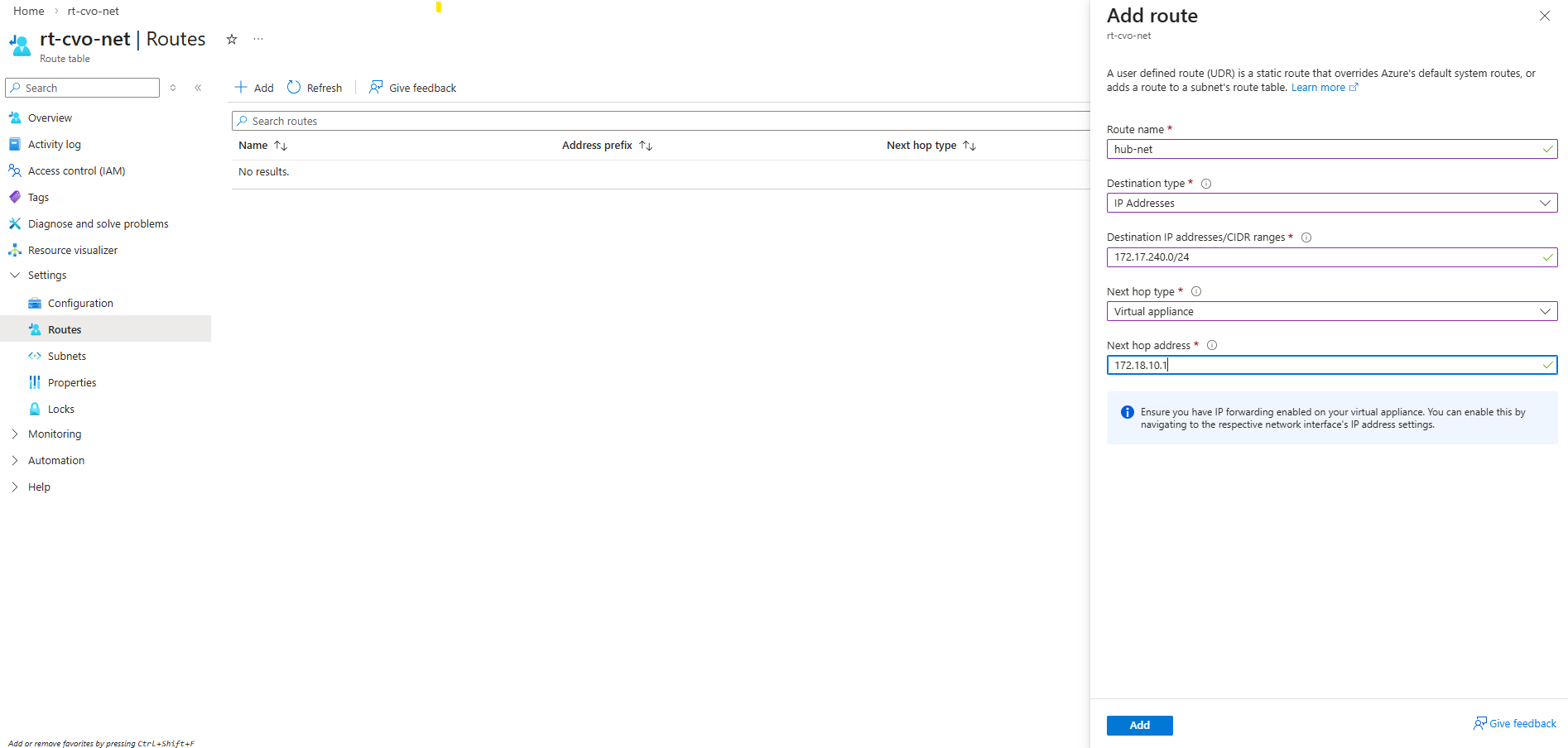
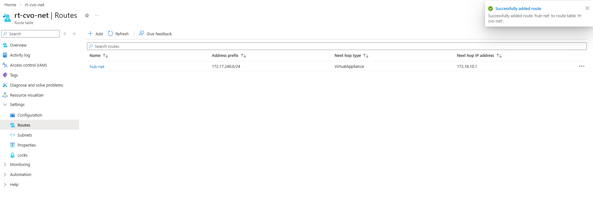
This new route table we now need to associate with our CVO virtual network and subnet in which the CVO nodes (VMs) and connector VM is running.
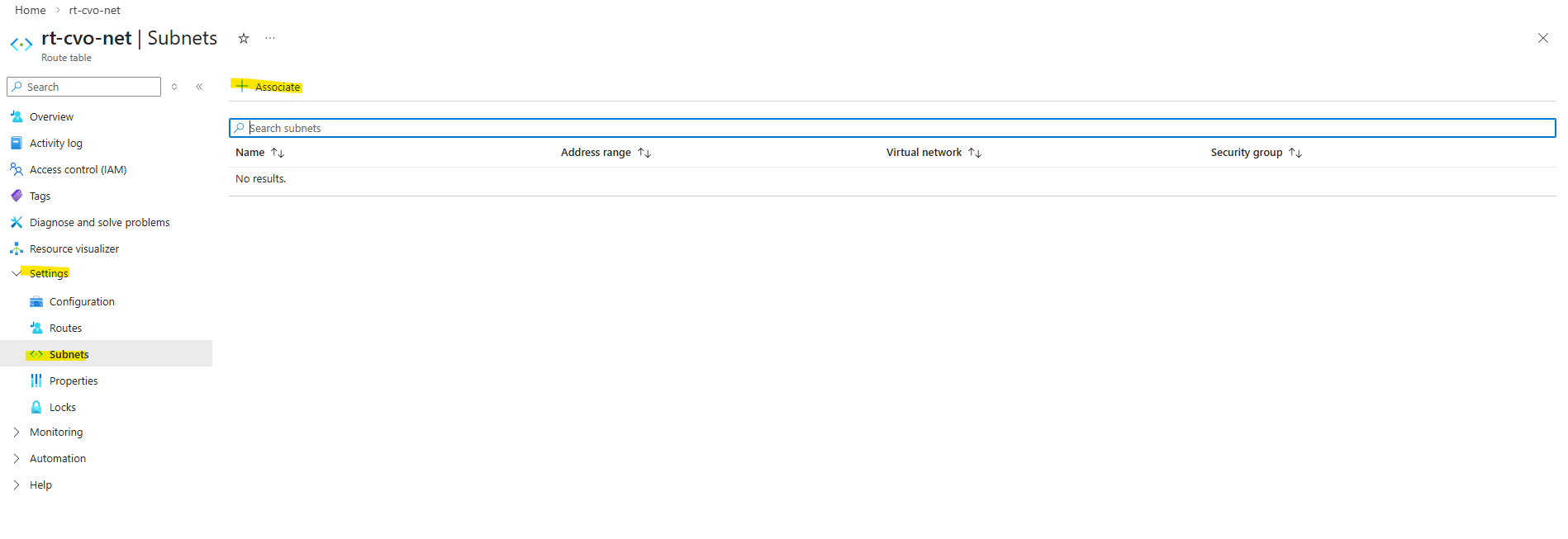
Selecting the CVO virtual network and subnet.
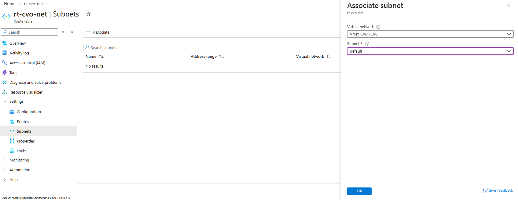
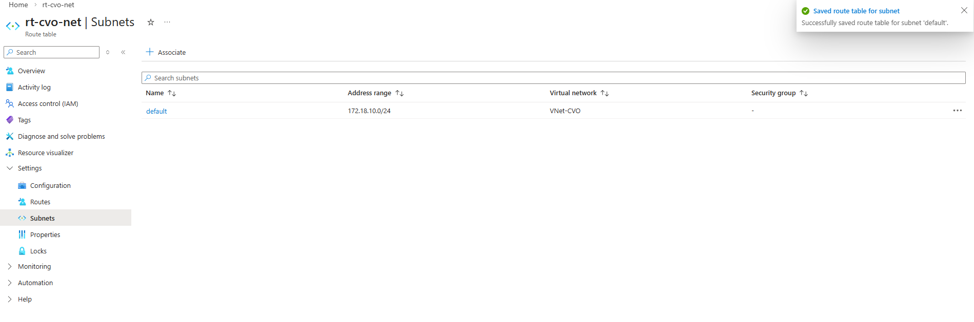
I will also have to add a further route to this new route table which will show the route to my on-premise network 10.0.0.0/24.
The next hop for my on-prem network is the internal network interface and IP
172.17.240.250of my pfSense appliance which as mentioned is establishing a site-to-site VPN tunnel with my on-prem network.For the next hop type we need to select virtual appliance.
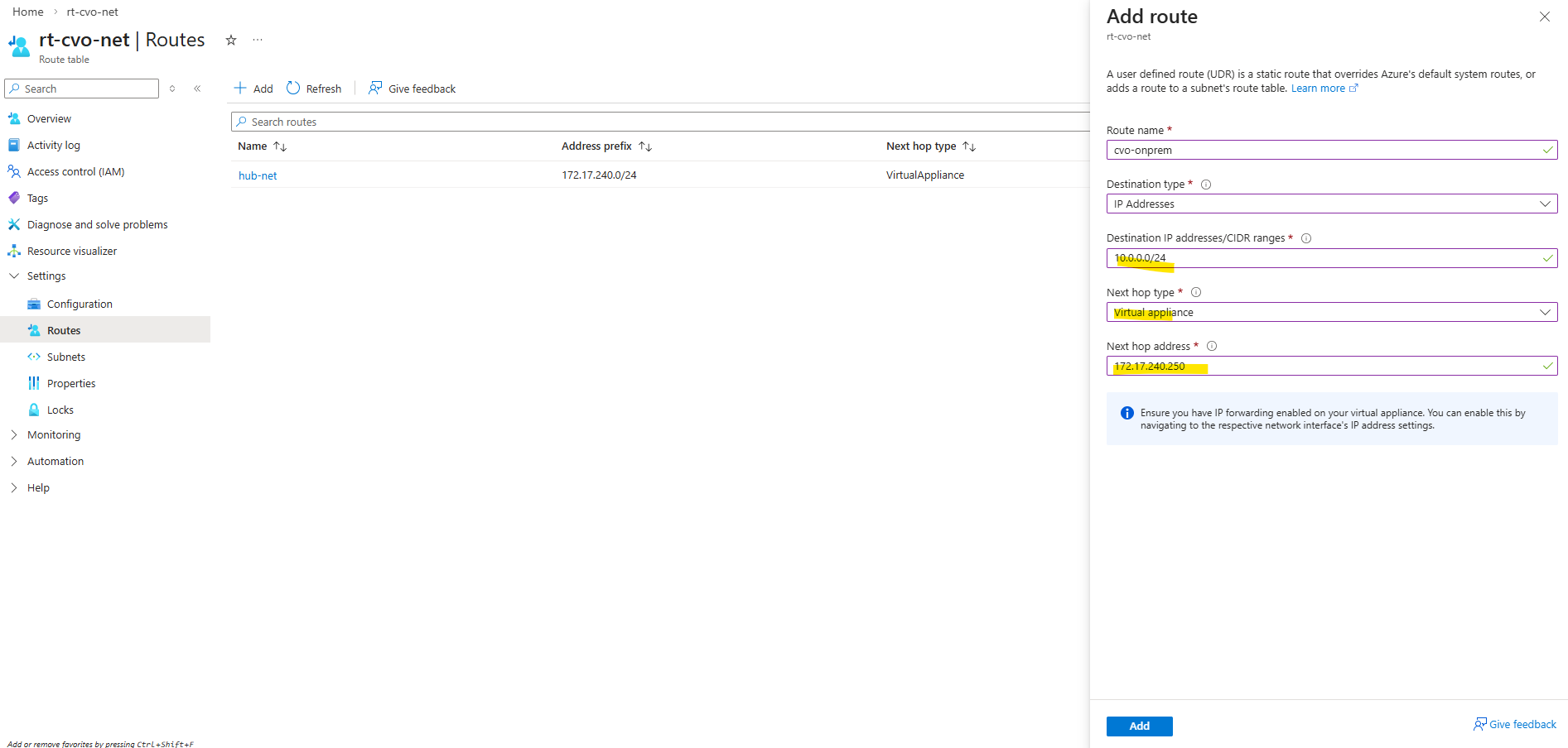
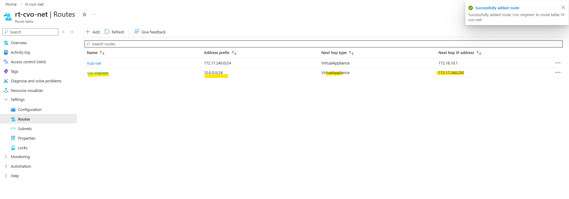
Below the we can see all routes the connector VM (OS) itself is aware of.
In Azure, every subnet automatically receives a default route pointing to the first usable IP address (e.g.
172.18.10.1), which represents Azure’s software-defined gateway.Virtual machines always forward traffic to this gateway, while actual routing decisions are handled by Azure using user-defined routes (UDRs).
In our setup, traffic destined for the on-prem network is forwarded via a UDR to the pfSense VM in the hub VNet, which then routes it through the site-to-site VPN.
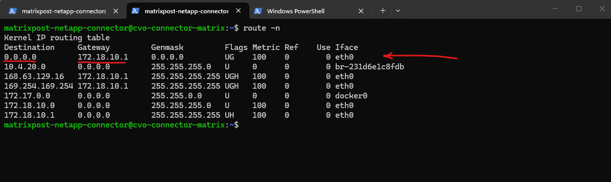
But how does our Cloud Volume ONTAP systems (nodes and connector) know where to send traffic for on-prem networks?
This is where our previously created User Defined Routes (UDRs) come into play.
CVO does NOT know about pfSense directly
CVO only knows: “send traffic to my default gateway”
Azure routing decides what happens nextThe route table associated with the CVO subnet tells Azure that traffic for
10.0.0.0/24must be forwarded to172.17.240.250(internal NIC of pfSense).So the routing logic finally is, CVO sends traffic to its default gateway (
172.18.10.1), Azure checks the UDR attached to the subnet and Azure’s internal routing fabric forwards packets destined to my on-prem network10.0.0.0/24by sending it to the definded next hop: Virtual appliance →172.17.240.250(pfSense)
CVO (172.18.10.x)
   ↓
Azure default gateway (172.18.10.1)
   ↓
UDR attached to subnet:
   10.0.0.0/24 → next hop: 172.17.240.250
   ↓
pfSense VM (Hub VNet)
   ↓
Site-to-Site VPN
   ↓
On-prem network
Testing if the connector VM can already ping my on-prem virtual machine with the IP address 10.0.0.70.
The connector VMs IP address is
172.18.10.4.
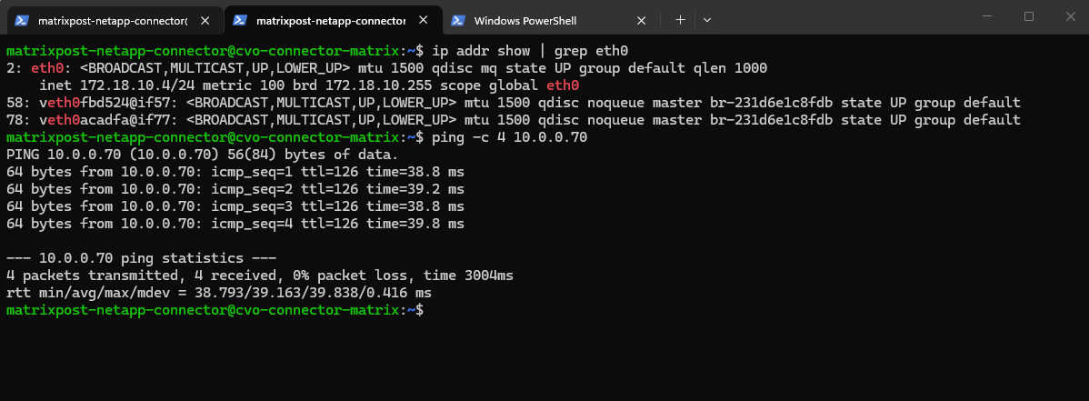
And vice versa, pinging the connector VM from my on-prem virtual machine (here my domain controller).
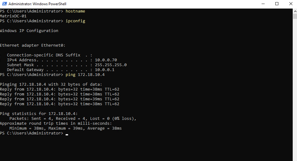
Next I will test if I can ping all IP addresses of the CVO cluster from on-premise.
To determine these IP addresses first, I will run the following command which lists all IP addresses (LIFs) in the cluster.
matrixcvo::> network interface show
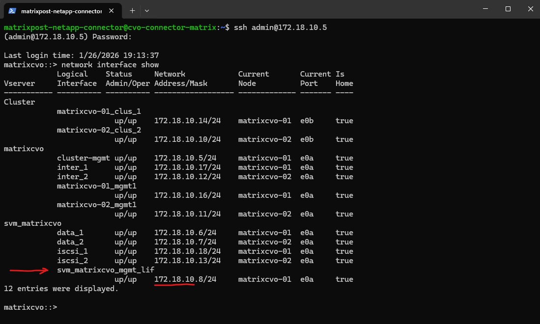
Below I will check if can ping the SVM on which I want to enable cifs/smb on and therefore need to join it to my on-prem Active Directory. Looks good.
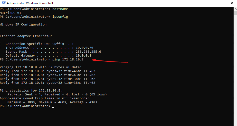
On the CVO subnet threre is no NSG assigned to as we previously checked and therefore no traffic is filtered on the virtual network and subnet itself.
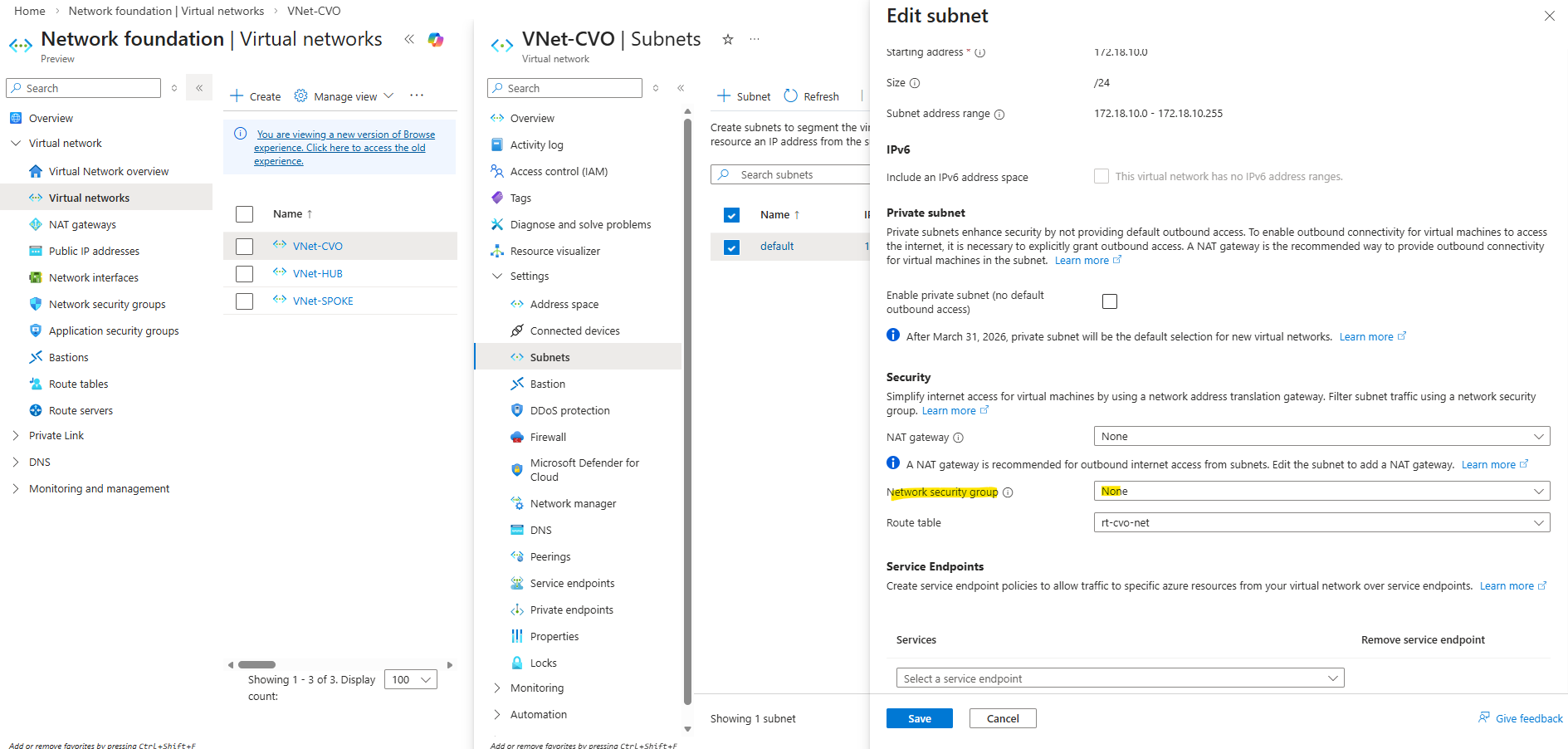
Instead a NSG is attached directly to the network interface of the nodes (VMs) like shown below. The same as for the connector VM but with different by default configured inbound/outbound rules by the NetApp console during deployment of the CVO.
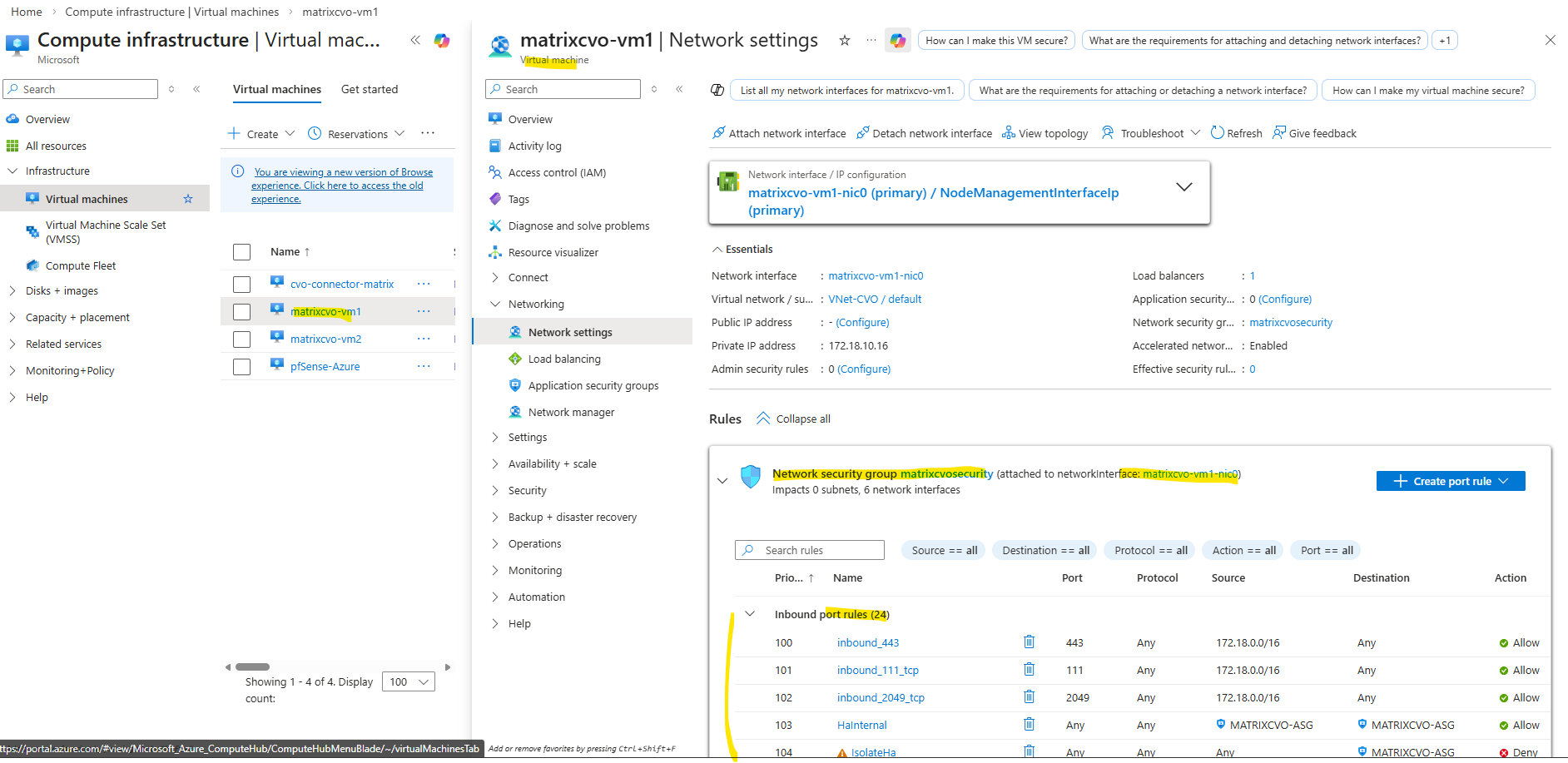
Inbound traffic for VNet to VNet and Azure load balancer to Any is not filtered and allowed in general.
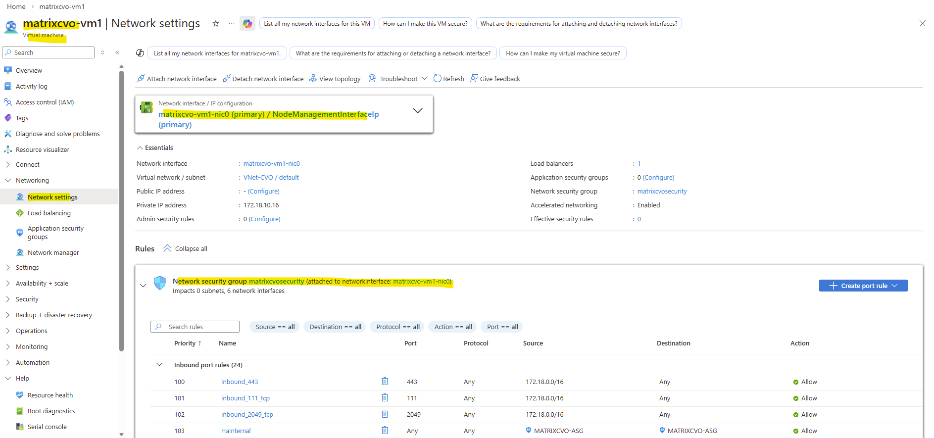
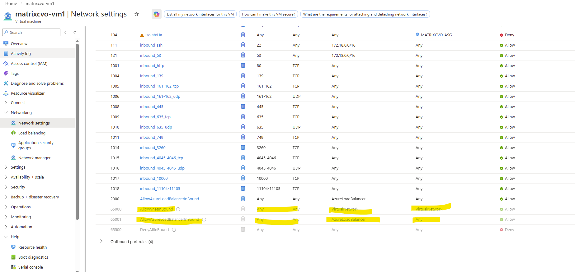
Outbound traffic is not filtered and allowed in general.
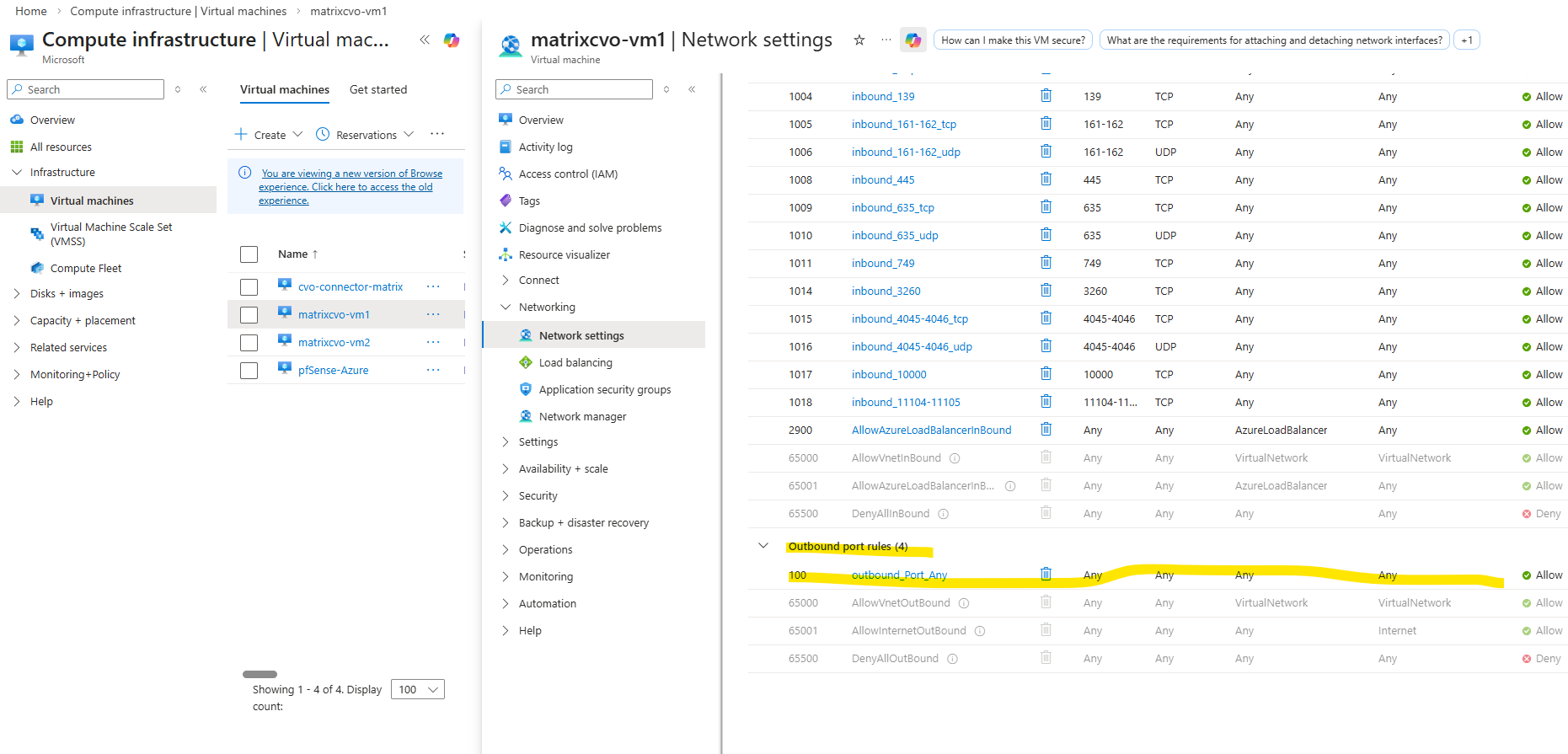
Behind the Scenes of ONTAP HA: How SVMs and LIFs Survive a Node Failure
In an ONTAP HA pair, failover does not involve copying data or synchronizing configurations at the time of failure.
Both nodes already have access to the same storage and share a synchronized cluster configuration, including SVM definitions and network interfaces.
When a node fails, its partner immediately takes ownership of the affected aggregates and logically migrates the data LIFs to itself.
Because LIFs are logical objects and the data is already accessible on both nodes, the failover process is fast and does not require any data movement.
Clients simply reconnect to the same IP addresses, making the failover largely transparent. This design ensures high availability while avoiding the overhead of real-time replication during an outage.
The preconfigured SVM by the NetApp console when deploying CVO in Azure, also has two data LIFs (data_1 and data_2).
When a Cloud Volumes ONTAP system is deployed, NetApp automatically creates iSCSI LIFs on the default SVM, even if iSCSI is not actively used.
These LIFs are created to ensure protocol readiness and proper HA design, allowing block services to be enabled later without reconfiguration. The presence of iSCSI LIFs does not mean that iSCSI is active or exposed.
In ONTAP, all storage access, including block storage via iSCSI or FC, is provided through an SVM. Just like SMB or NFS, iSCSI and FC requires its own SVM with dedicated LIFs. The SVM acts as the protocol endpoint, while the underlying data remains accessible to both nodes in an HA pair. This design allows consistent management and high availability across all protocols.
matrixcvo::> network interface show -vserver svm_matrixcvo
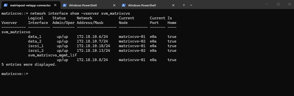
The “Allowed Protocols” field in an SVM indicates which protocols the SVM is permitted to use, not which ones are actively running or supported by the platform.
In Cloud Volumes ONTAP,
Fibre Channelappears as an allowed protocol because ONTAP uses a unified code base, but FC is not operationally supported due to the lack of physical FC hardware in cloud environments.
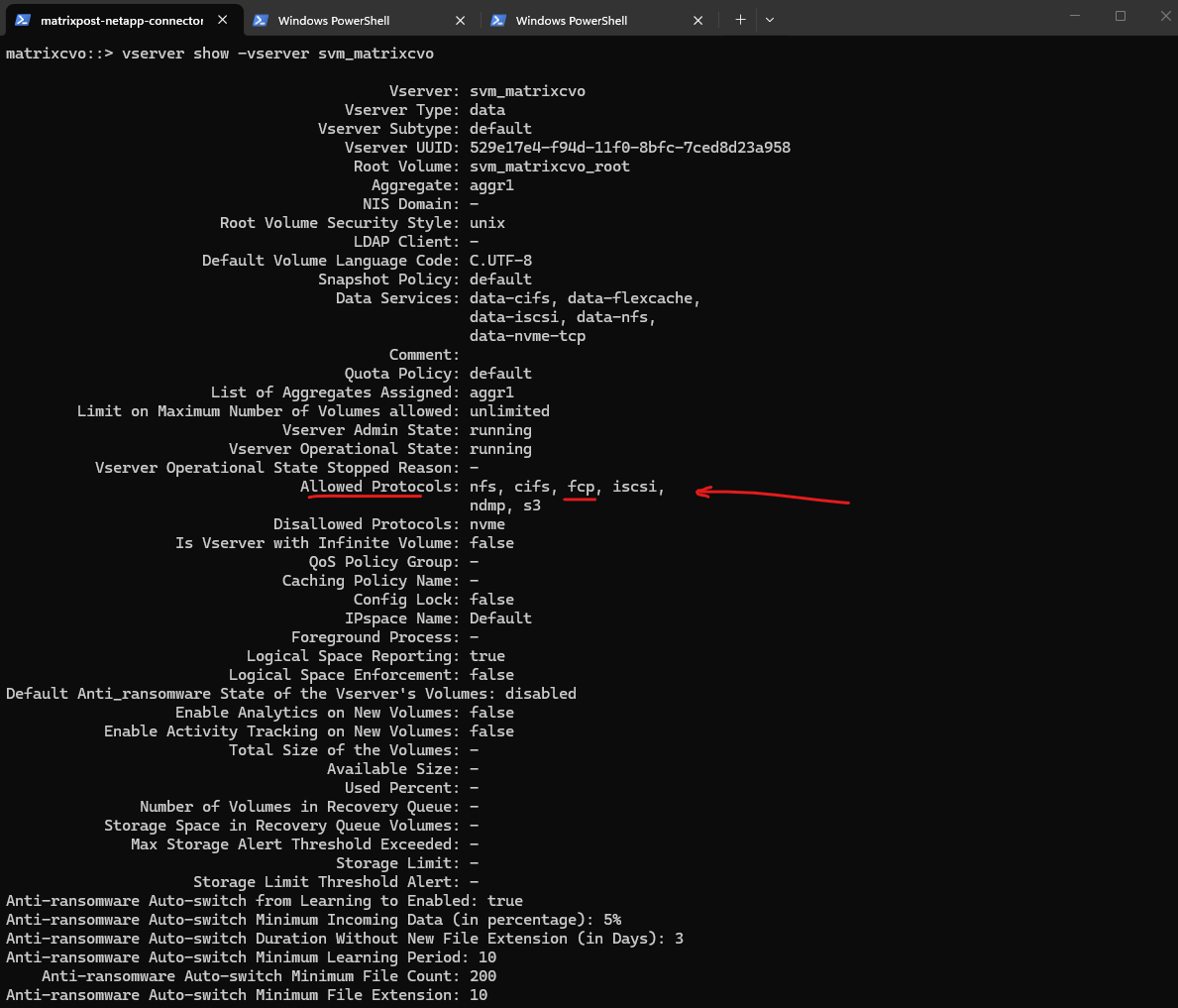
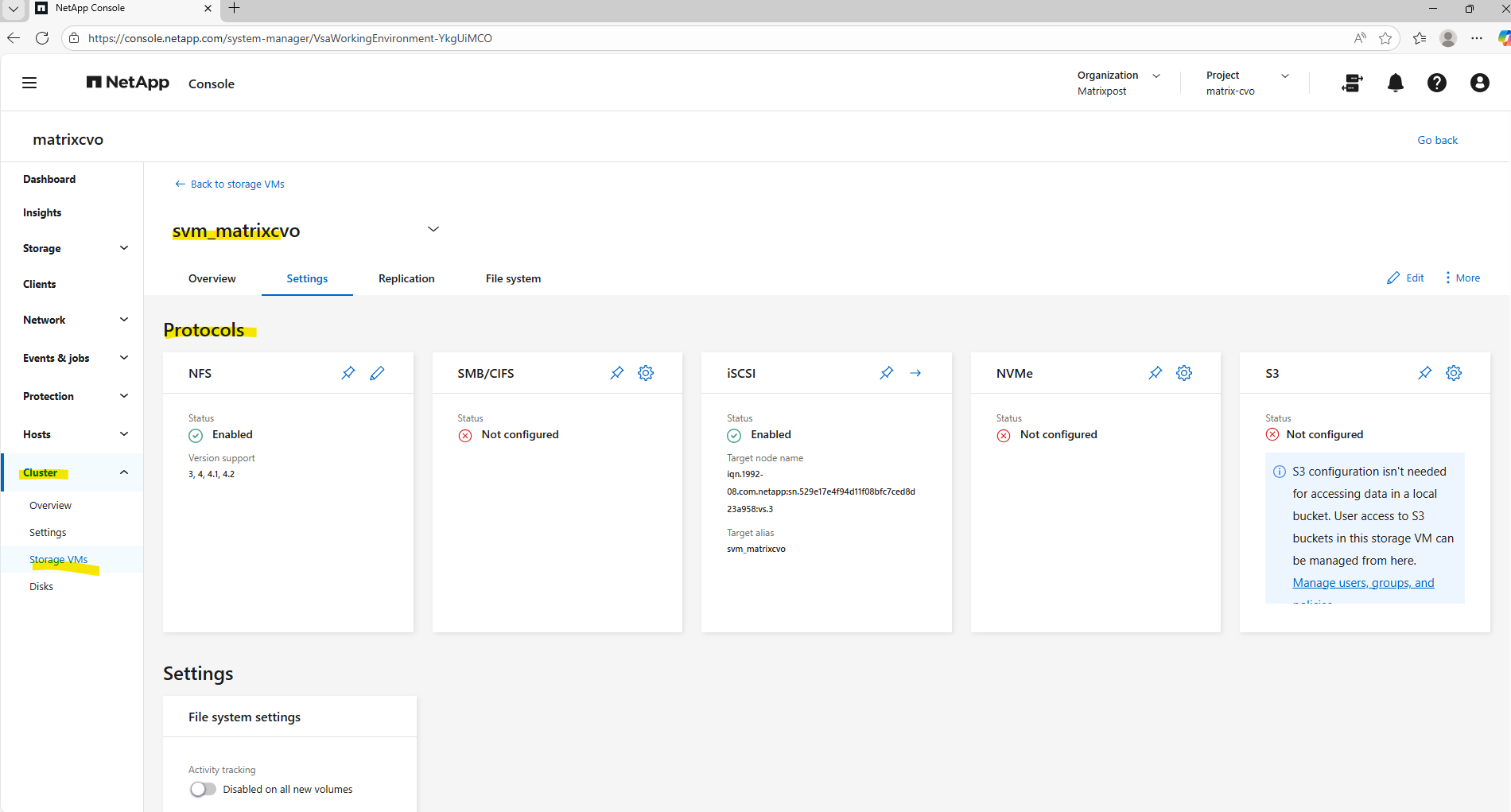
Troubleshooting
Troubleshooting Missing Qtree Quotas in ONTAP CLI and System Manager
Setting up quotas in ONTAP can occasionally lead to a confusing state where a rule is visible in the policy configuration but completely absent from the active reporting dashboard.
This occurs because ONTAP treats the Quota Policy (your intended configuration) and the Quota Database (the live enforcement engine) as two separate layers that do not always synchronize automatically when a new target is added.
To resolve this, a manual re-initialization is often required to force the volume to scan the file system and officially begin tracking the new qtree or user.
Verify the Policy: Use volume quota policy rule show to confirm the rule exists.
The
volume quota reportcommand serves as the definitive audit tool for storage administrators, providing a real-time view of space consumption and limit enforcement across individual qtrees. It is the essential ‘sanity check’ to ensure that the ONTAP kernel is actively tracking all defined targets and accurately calculating usage against the established hard and soft limits.
matrixcvo::> volume quota report -vserver svm_matrix_nfs -volume vol_nfs_data02_qtree
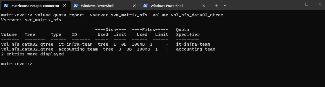
Toggling the quota state off and then on acts as a definitive reset that forces the ONTAP kernel to discard its stale enforcement data and perform a fresh scan of the filesystem.
This “workaround” is the most reliable way to synchronize the active quota database with your updated policy rules, ensuring that newly created qtree targets are officially recognized and monitored.
# Toggling the quota state off and then on for the NFS volume
matrixcvo::> volume quota off -vserver svm_matrix_nfs -volume vol_nfs_data02_qtree
matrixcvo::> volume quota on -vserver svm_matrix_nfs -volume vol_nfs_data02_qtree

# Toggling the quota state off and then on for the CIFS volume
matrixcvo::> volume quota off -vserver svm_matrix_cifs  -volume vol_cifs_data0_data02_qtree
matrixcvo::> volume quota on -vserver svm_matrix_cifs  -volume vol_cifs_data02_qtree
All of my configured quotas shown up afterwards.
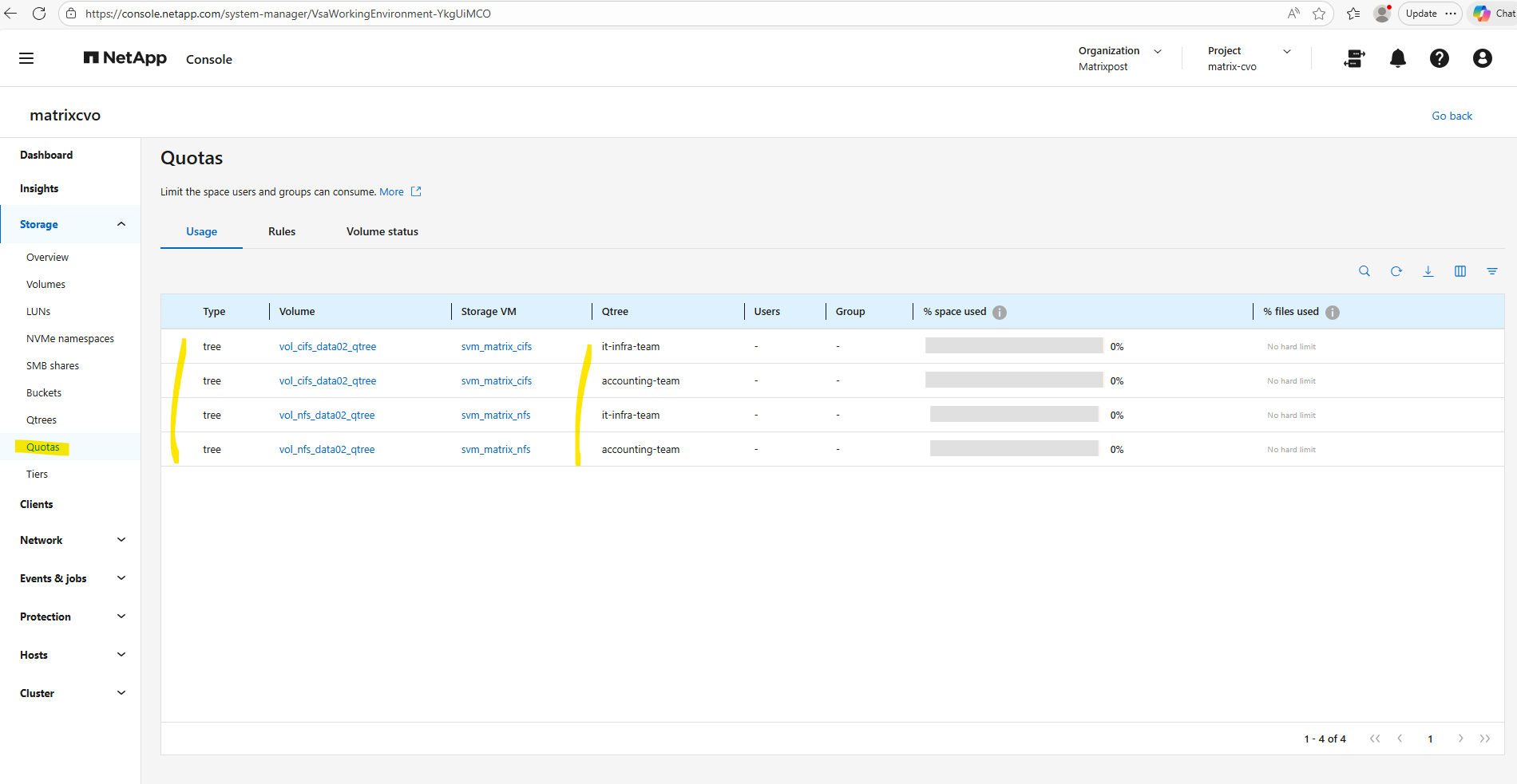
In Part 4 of the series, we shift the focus to security and take a closer look at how antivirus protection is implemented in Cloud Volumes ONTAP using ONTAP VSCAN.
Links
Plan your Cloud Volumes ONTAP configuration in Azure
https://docs.netapp.com/us-en/storage-management-cloud-volumes-ontap/task-planning-your-config-azure.htmlLaunch Cloud Volumes ONTAP in Azure
https://docs.netapp.com/us-en/storage-management-cloud-volumes-ontap/task-deploying-otc-azure.htmlLaunch a Cloud Volumes ONTAP HA pair in Azure
https://docs.netapp.com/us-en/storage-management-cloud-volumes-ontap/task-deploying-otc-azure.html#launch-a-cloud-volumes-ontap-ha-pair-in-azureSupported configurations for Cloud Volumes ONTAP in Azure
https://docs.netapp.com/us-en/cloud-volumes-ontap-relnotes/reference-configs-azure.htmlLicensing for Cloud Volumes ONTAP
https://docs.netapp.com/us-en/storage-management-cloud-volumes-ontap/concept-licensing.htmlAzure region support
https://bluexp.netapp.com/cloud-volumes-global-regionsLearn about NetApp Console agents
https://docs.netapp.com/us-en/console-setup-admin/concept-agents.htmlLearn about data tiering with Cloud Volumes ONTAP in AWS, Azure, or Google Cloud
https://docs.netapp.com/us-en/storage-management-cloud-volumes-ontap/concept-data-tiering.htmlLearn about ONTAP LIF compatibility with port types
https://docs.netapp.com/us-en/ontap/networking/lif_compatibility_with_port_types.htmlLearn about managing ONTAP SMB share-level ACLs
https://docs.netapp.com/us-en/ontap/smb-admin/manage-smb-level-acls-concept.html