Mastering Hyper-V Clusters with iSCSI and Multipath I/O (CSV)
While Storage Spaces Direct leverages local disks for software-defined storage as shown in my last post here, many Hyper-V clusters are still built on shared storage provided via iSCSI.
In this post, I’ll walk through building a Hyper-V failover cluster using iSCSI-attached disks as Cluster Shared Volumes (CSV), including a multipath I/O (MPIO) setup to provide redundant and performant storage access.
About how to set up a Hyper-V Cluster you can read my following post.
About how to set up a Microsoft iSCSI Target Server you can read my following post.
My Lab Setup
This lab runs entirely on VMware, with two Hyper-V servers deployed as nested virtual machines to simulate a real-world failover cluster.
The iSCSI disk is created on a Microsoft iSCSI Target server which will also run as virtual machine in my vSphere lab environment.
Creating an iSCSI Disk in Microsoft iSCSI Target Server
In this step, an iSCSI virtual disk is created on the Microsoft iSCSI Target Server to provide shared block storage for the Hyper-V cluster.
This disk will later be presented to all cluster nodes and used as the foundation for a Cluster Shared Volume (CSV).
Proper sizing and target configuration at this stage are essential to ensure reliable and consistent access from all Hyper-V hosts.
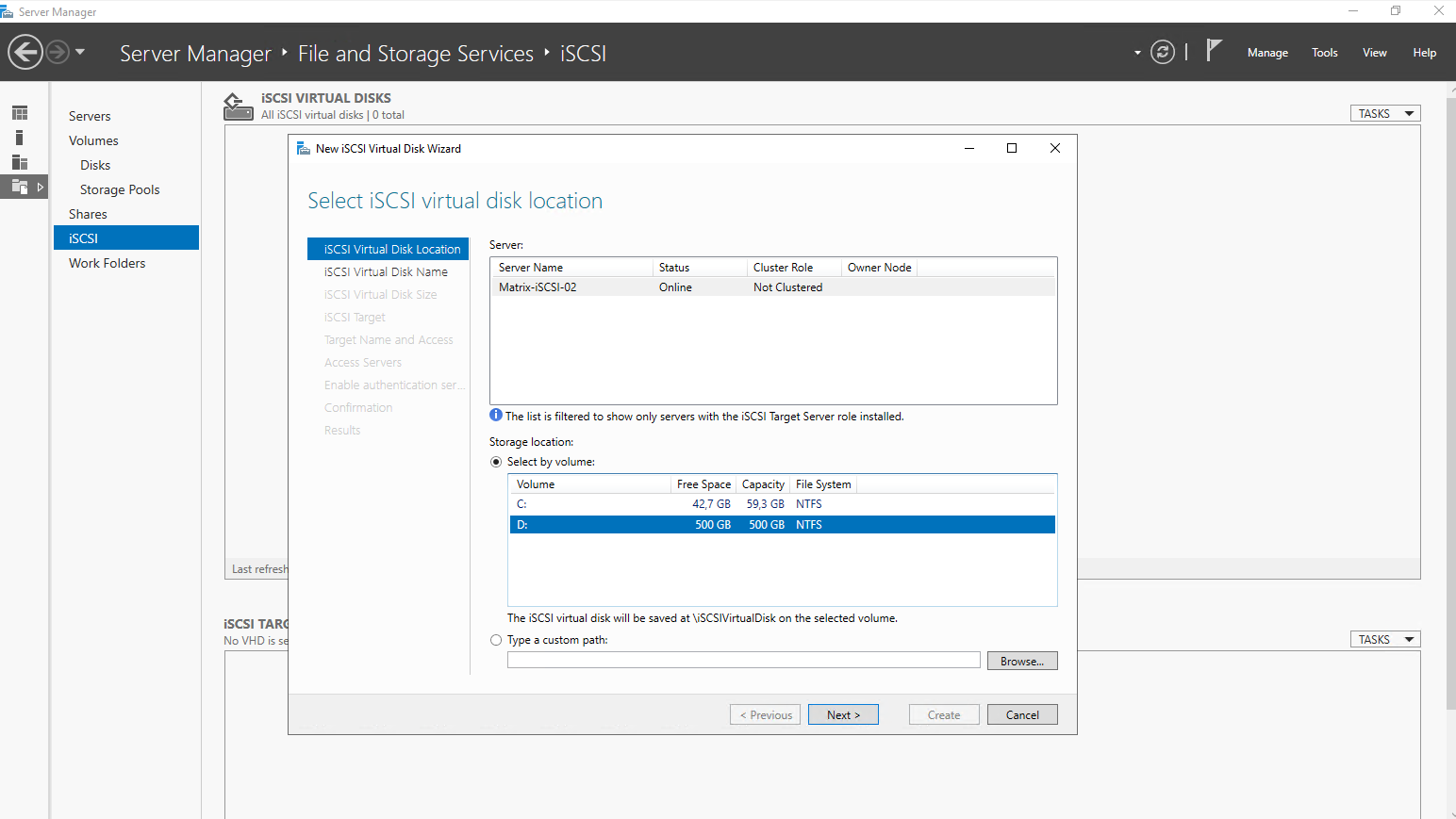
On the iSCSI Target Server and its Server Manager navigate to iSCSI and on the right top under Tasks select New iSCSI Virtual Disk … as shown below.

Select the location where to store the new iSCSI virtual disk. I will select here my local D:\ drive.
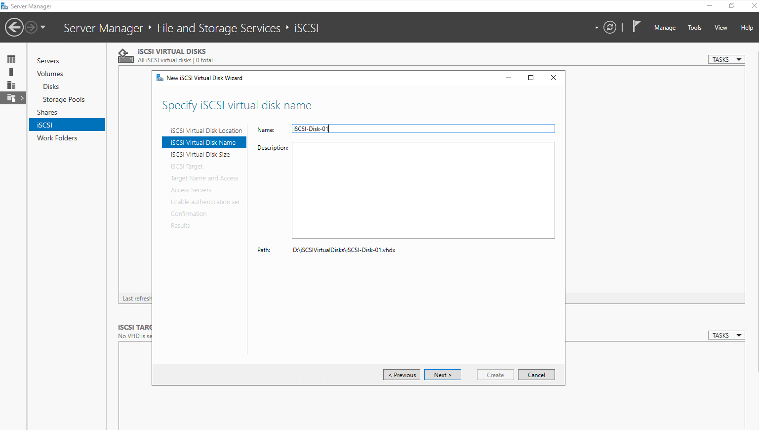
Enter a name for the new iSCSI virtual disk.
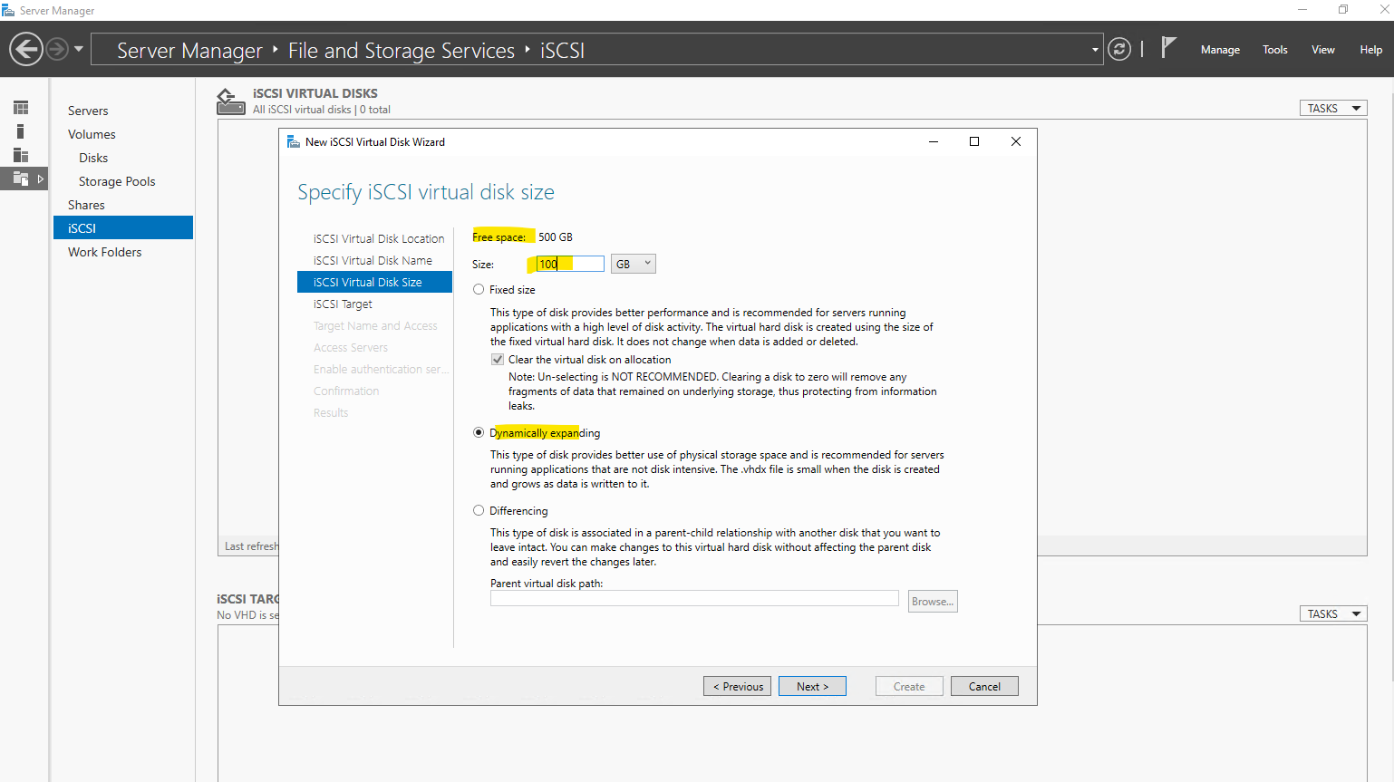
Specify the iSCSI virtual disk size and type, for my lab environment I will select Dynamically expanding.
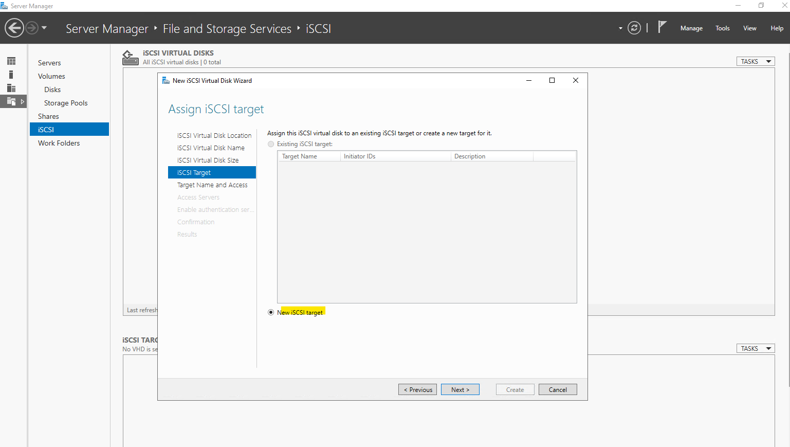
So far on the Server I haven’t created any iSCSI targets, so by default New iSCSI target is selected.
An iSCSI target represents a logical endpoint on the target server that exposes one or more virtual disks to remote initiators.
It defines which servers are allowed to connect and access the underlying storage via iSCSI. In a Hyper-V cluster scenario, the same iSCSI target is presented to all cluster nodes to provide shared storage for Cluster Shared Volumes.
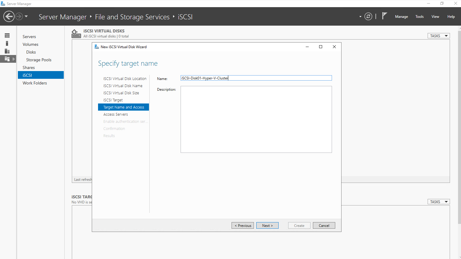
Specify a target name.
The iSCSI target name uniquely identifies the storage target and is used by initiators to establish a connection. It follows the standardized IQN (iSCSI Qualified Name) format, which ensures global uniqueness across environments. Using a clear and descriptive target name helps with identification, troubleshooting, and long-term management of shared storage.
The iSCSI target name is also visible later in Disk Management on the initiator hosts. It is shown as part of the disk information and helps identify which disks are connected via iSCSI and from which target they originate. This makes it easier to distinguish shared iSCSI disks from local or other attached storage during setup and troubleshooting.
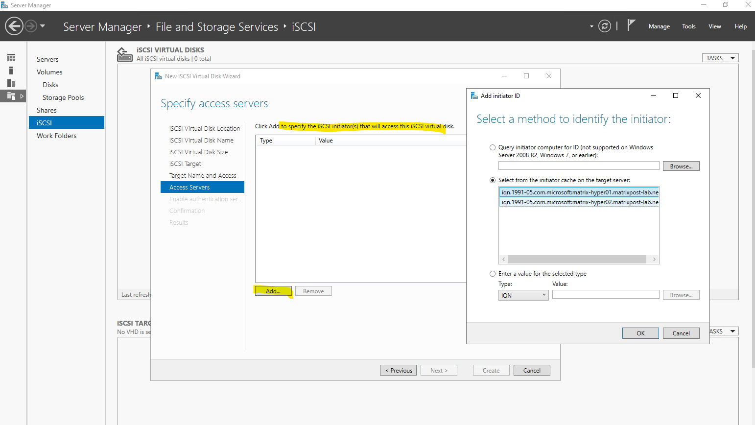
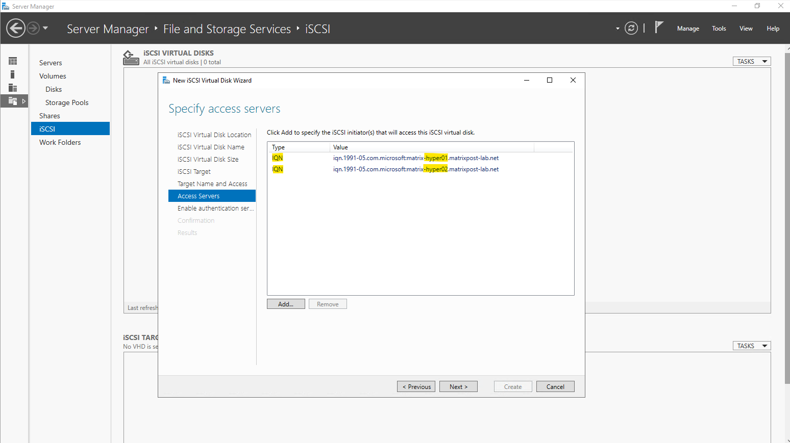
Specify the access server, our both Hyper-V Hosts (Cluster Nodes). For the type I will choose IQN which is recommended and the best option. In my case the target server has the IQNs of both Hyper-V server already in his cache and I just need to select here Select from the initiator cache on the target server.
When defining iSCSI initiators, the target server needs a way to identify which hosts are allowed to connect.
IQN is the most common and reliable option, as it uniquely identifies the initiator at the iSCSI protocol level and remains stable even if IP or MAC addresses change.
DNS name, IP address, and MAC address are easier to understand but can change over time, making them less suitable for clustered or long-lived environments.
An IQN (iSCSI Qualified Name) is a globally unique identifier used by the iSCSI protocol to identify initiators and targets. It follows a standardized format that includes a reversed domain name and a unique suffix, ensuring uniqueness across environments. During connection, the initiator presents its IQN to the target, which uses it to authenticate and authorize access to the exposed iSCSI disks.
- IQN (recommended) → Stable, protocol-native, best practice for clusters
- DNS name → Readable, but depends on DNS and hostname stability
- IP address → Simple, but breaks if addresses change
- MAC address → Rarely used; fragile if NICs are replaced
An iSCSI target server can learn initiator IQNs in two ways. Either the IQN is added manually after checking it on the initiator host, or it is discovered automatically when the initiator first connects to the target using its FQDN or IP address.
In the latter case, the target server caches the initiator’s IQN as in my case shown above, allowing it to be selected directly when configuring access permissions.
To manually adding the IQN in case it is not already in the target server’s cache, we first need to determine it on the initiator host(s), in my case on both Hyper-V Server (Nodes).
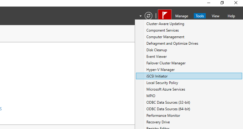
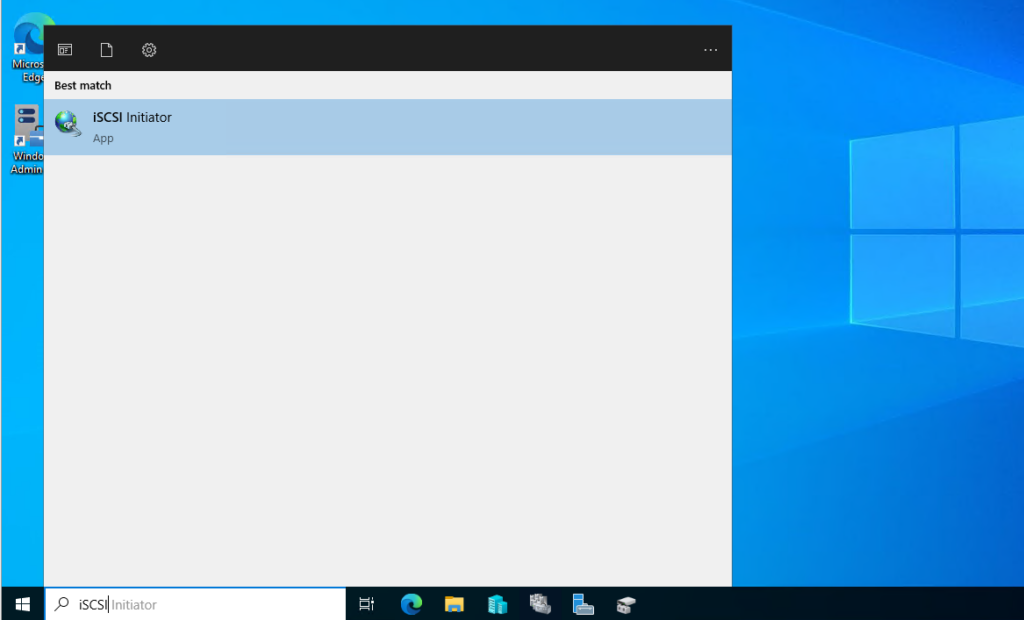
Therefore we can open the iSCSI initiator tool from the Server Manager on both Hyper-V Hosts like shown below.
Or from the search bar as shown below.
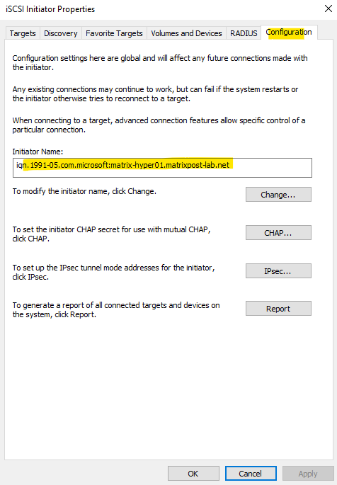
In the Configuration tab we will find the Initiator Name.
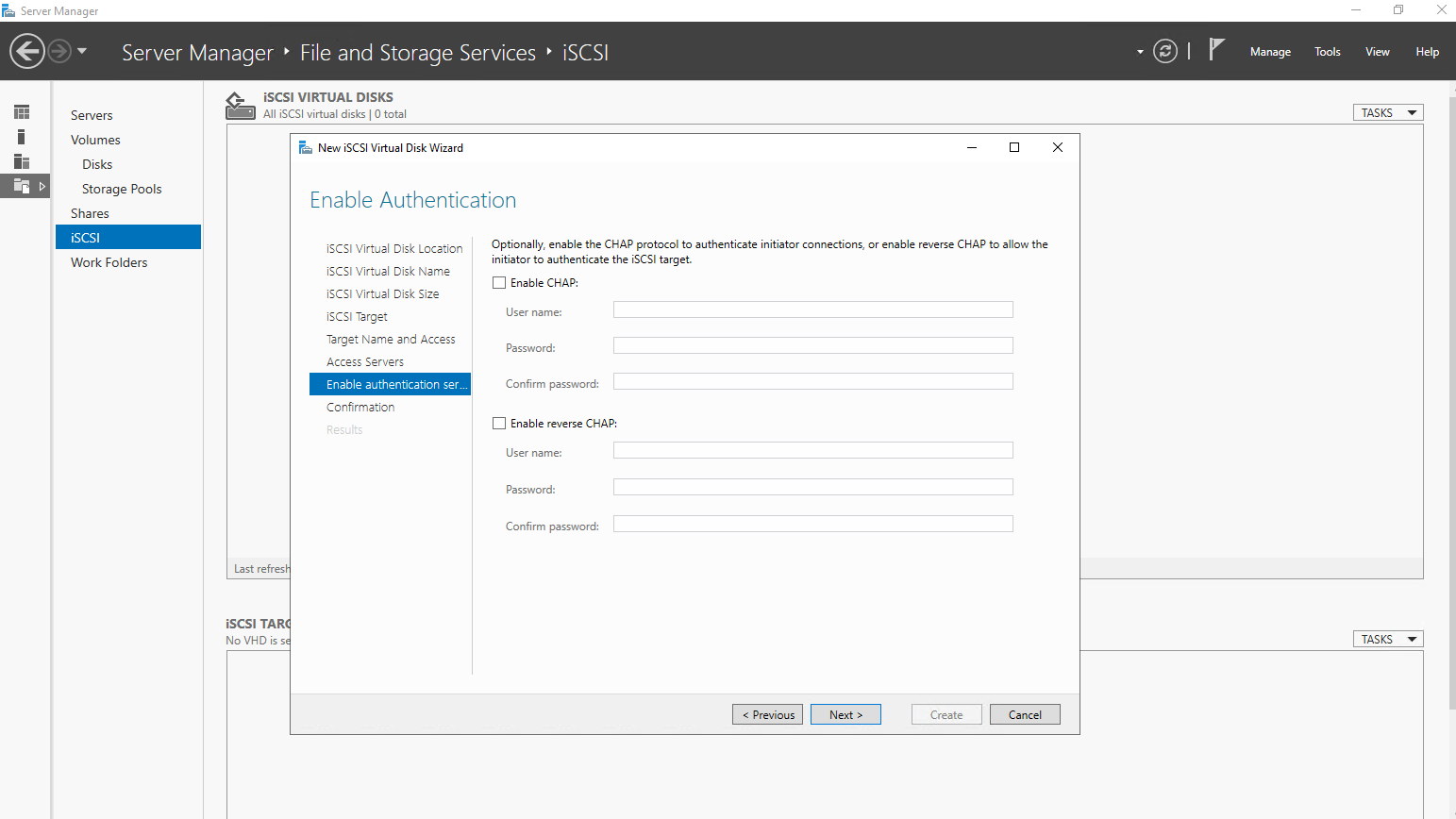
For my lab environment I will skip enabling authentication.
The Enable Authentication option on the iSCSI target server configures CHAP authentication to control which initiators are allowed to access the target.
In trusted environments or isolated lab setups, it is common and generally safe to skip authentication and rely on network-level security instead.
For production environments, however, enabling CHAP is recommended to prevent unauthorized access to shared iSCSI storage.
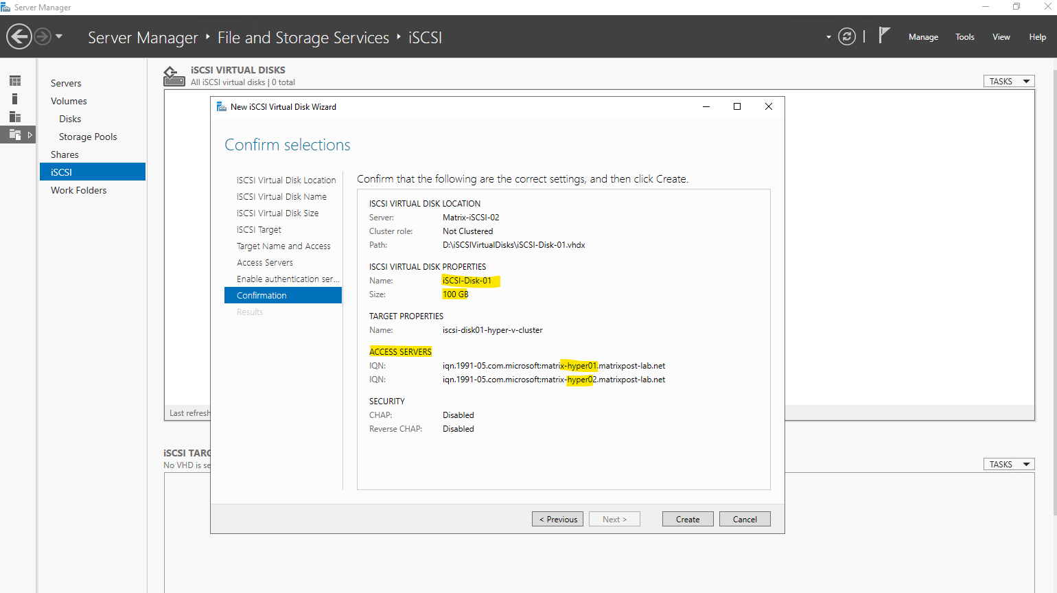
Finally we can click on Create.
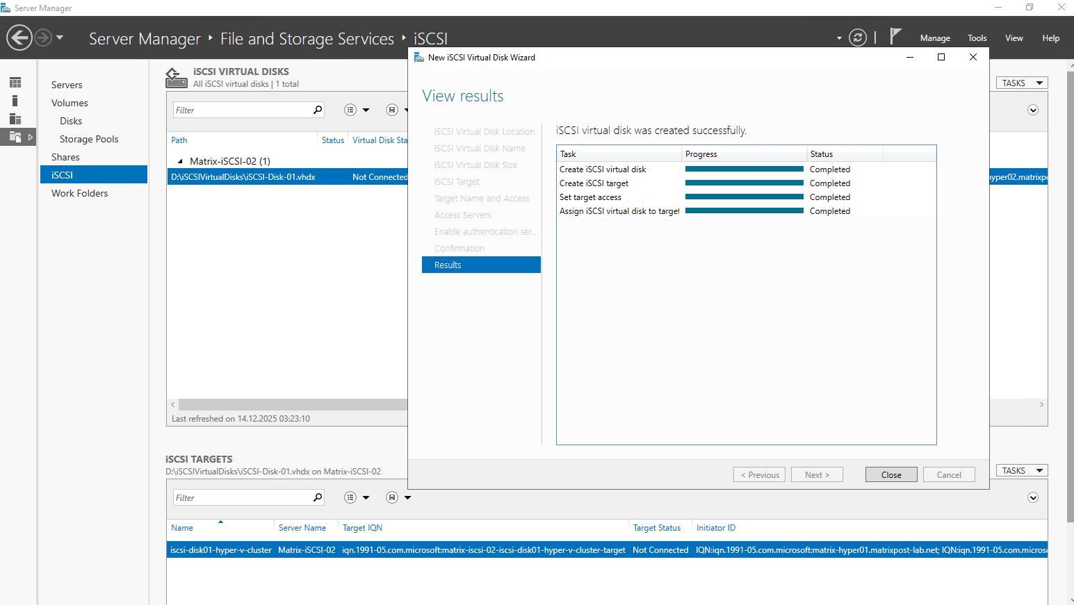
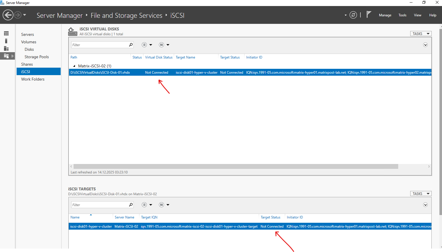
So far the iSCSI virtual disk is not connected to my both Hyper-V Hosts. The connection I will establish from both Hyper-V Hosts in the next section below.
The initial iSCSI connection is always initiated from the client hosts, also known as iSCSI initiators. The target server does not push disks to hosts; instead, each Hyper-V node must actively discover and connect to the iSCSI target.
Only after the initiators establish the connection does the shared disk become visible on the hosts.
Connecting the iSCSI Disk from the Hyper-V Hosts Using Multipath I/O (MPIO)
After the iSCSI disk and target have been created, the next step is to connect the storage from each Hyper-V host.
This is done using the built-in iSCSI Initiator tool in Windows, which allows the hosts to discover the target and establish a persistent connection.
Both cluster nodes must connect to the same iSCSI target to enable shared access for a Cluster Shared Volume (CSV).
So far both Hyper-V Hosts and its Disk Management tool will looks like this.
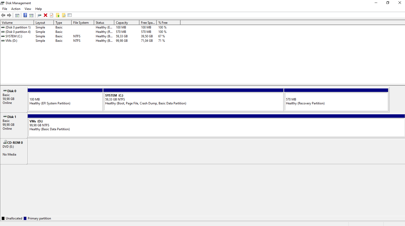
Actually they will also already have a CSV but from its local attached disks (Storage Spaces Direct S2D) as shown in my last post here.
The local attached disks used by S2D will not shown up above in the Disk Management tool.
When using Storage Spaces Direct, the local disks are abstracted and managed entirely by the cluster, which is why they do not appear as individual disks in the Disk Management tool on the Hyper-V hosts.
Once an S2D pool and CSV are created, storage is presented only through the CSV layer rather than as traditional disks.
In contrast, iSCSI-attached disks are visible in Disk Management on all Hyper-V hosts, even after being added as a Cluster Shared Volume, because they are presented as shared block devices to each initiator.
On the iSCSI target server, supporting multipath simply requires exposing the target through multiple network interfaces with dedicated IP addresses; no special MPIO configuration is needed on the target itself.
My iSCSI target server uses a three-NIC design: one interface for standard host management traffic and two dedicated interfaces exclusively for iSCSI connectivity.
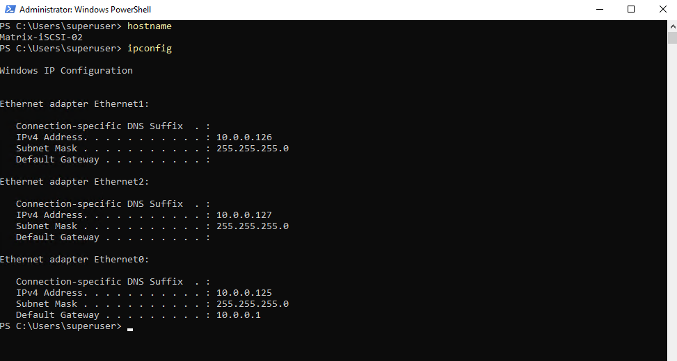
A three-NIC layout, one NIC for management/host traffic and two dedicated NICs for iSCSI, is a standard and well-established design.
Separating management traffic from storage traffic improves stability, performance, and troubleshooting, while the two iSCSI NICs enable multipath I/O for redundancy and load balancing. This design scales well from lab environments to production deployments.
In this lab environment, the two NICs dedicated to iSCSI traffic are connected to the same network as the host management interface for simplicity.
While this works well for testing and demonstrations, it is not recommended for production use. In production environments, iSCSI traffic should be isolated on a dedicated network or VLAN to avoid contention and improve performance and reliability.
On the initiator (Hyper-V hosts), MPIO must be enabled and multiple iSCSI sessions are established to the same target using different source and destination IP addresses. This is where multipath is actually configured and controlled, providing path redundancy and load balancing.
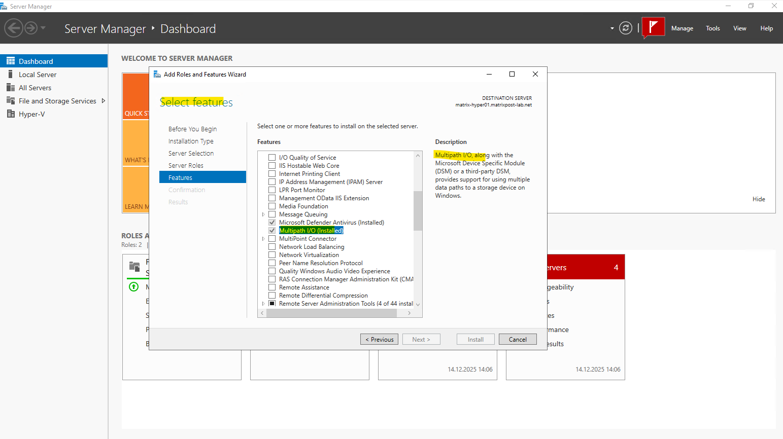
Before establishing multipath iSCSI connections, the Multipath I/O (MPIO) feature must be installed on both Hyper-V hosts.
MPIO enables the operating system to manage multiple iSCSI paths to the same storage device for redundancy and load balancing.
After installing the feature, a reboot is required before configuring and using multipath connections in the iSCSI Initiator.
We can install the Multipath I/O (MPIO) feature either by using the Server Manger or PowerShell as shown below.
Installing by using PowerShell:
PS> Install-WindowsFeature -Name Multipath-IO -IncludeManagementTools

# Optional after the reboot, enable iSCSI support in MPIO. This ensures that iSCSI disks are automatically claimed by MPIO and managed using multiple paths.
PS> Enable-MSDSMAutomaticClaim -BusType iSCSI
The MPIO tool we can either open by using the Server Manager or by using the run dialog as shown below.
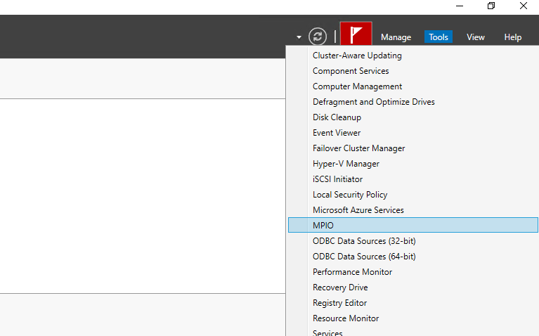
In the Run dialog type:
mpiocpl.exe
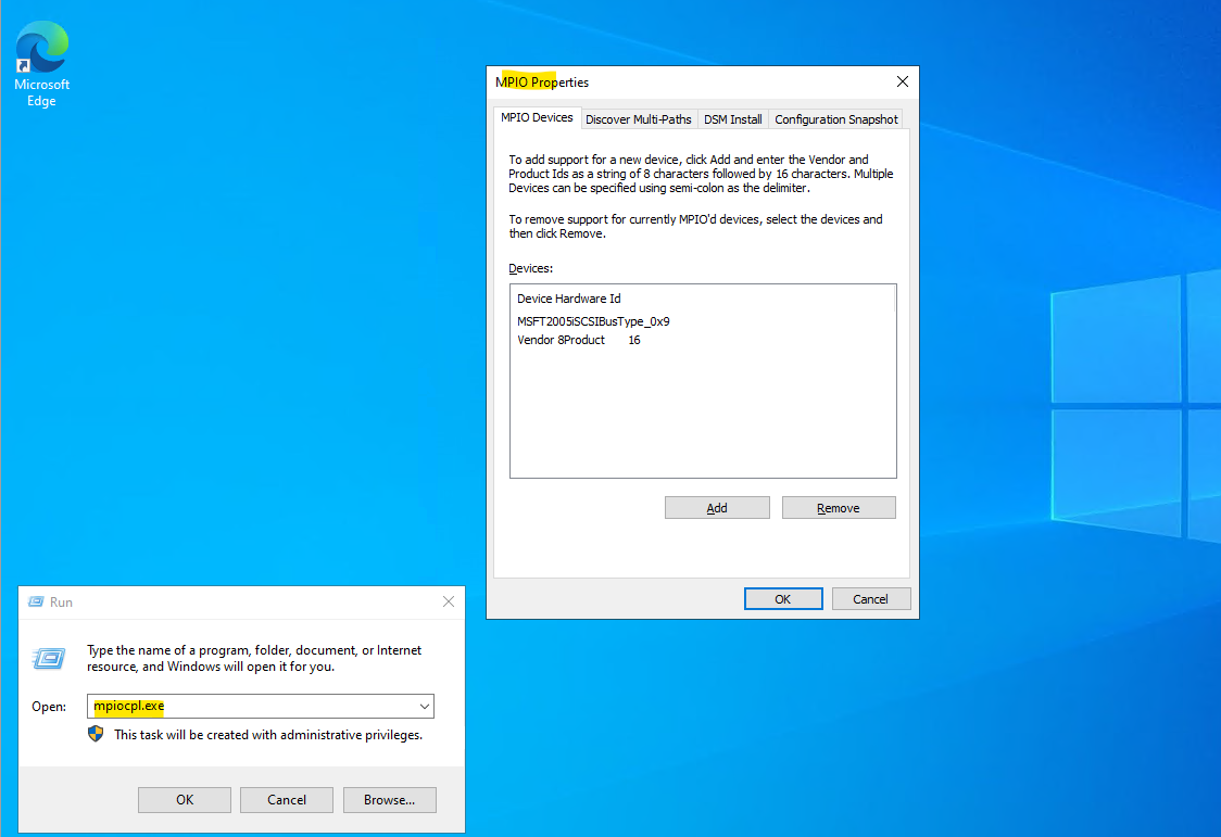
iSCSI support in MPIO can also be enabled through the Discover Multi-Paths tab by checking “Add support for iSCSI devices” and clicking Add
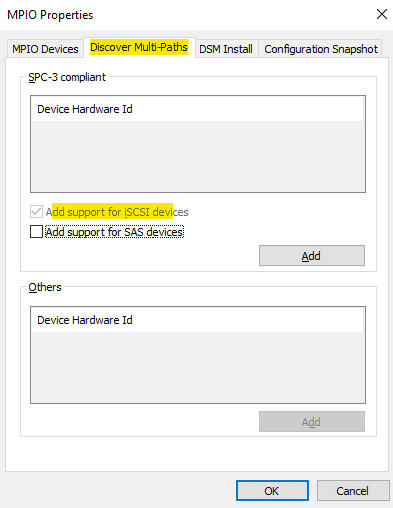
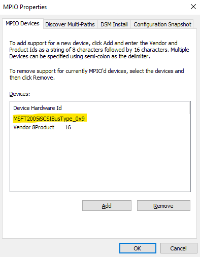
This action registers the Microsoft iSCSI bus with MPIO and results in the entry MSFT2005iSCSIBus Type_0x9 appearing on the MPIO Devices tab. Once added, iSCSI disks can be managed through multiple paths for redundancy and load balancing.
The entry “Vendor 8 Product 16” is a generic MPIO hardware ID used by Windows to represent storage devices that do not report a specific vendor/product string. It is added automatically by the MPIO framework and acts as a fallback identifier for certain SCSI or storage bus types. In most environments, this entry can be left as-is and does not require any manual configuration.
On the initiator (Hyper-V hosts) open the iSCSI initiator tool.
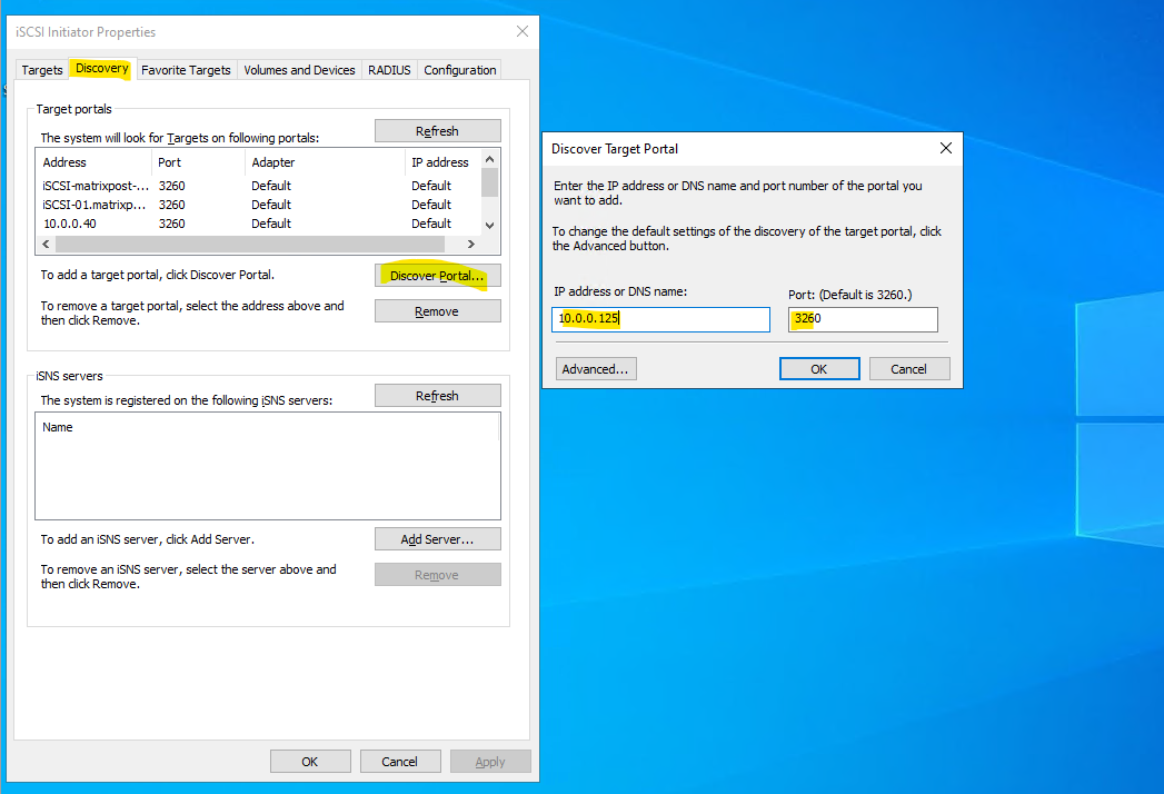
The recommended approach is to first add the iSCSI target server via the Discovery tab using Discovery Portal, specifying the IP address or DNS name (and port) of the target.
This allows the initiator to discover all available targets and is required for proper multipath (MPIO) configurations with multiple target IPs.
Quick Connect is convenient for simple, single-path setups, but it bypasses explicit discovery and is therefore less suitable for structured or multipath iSCSI deployments.
We can initially discover the iSCSI target using the host management IP as long as it is reachable, which causes the target’s IQN to appear under Discovered Targets as shown below.
So below I will enter the host management IP of the iSCSI target server and its default port.
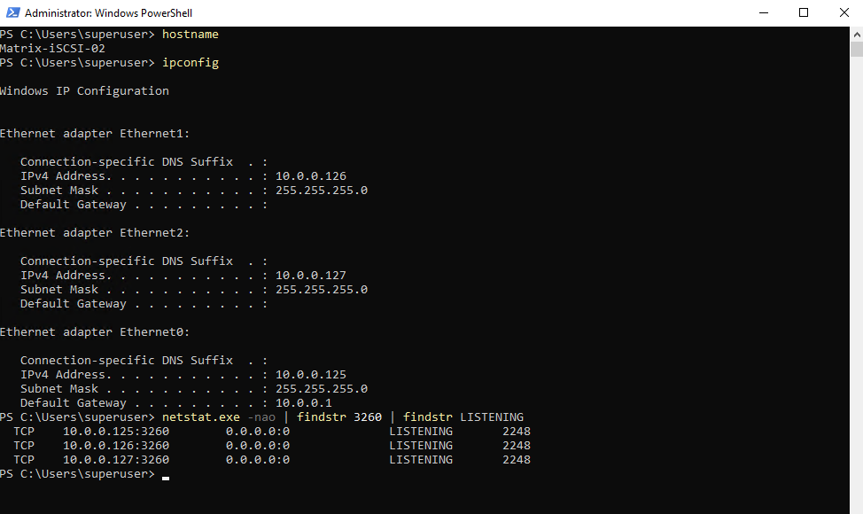
My iSCSI target server is finally listening on all three interfaces on TCP port 3260.
PS> netstat.exe -nao | findstr 3260 | findstr LISTENING
The iSCSI target server listens for incoming connections on TCP port 3260 on all configured network interfaces.
This includes the management interface as well as the dedicated iSCSI interfaces used for multipath connectivity.
TCP port 3260 is used by the iSCSI protocol for all communication between initiators and the target server. This includes target discovery, session establishment, login negotiation, and the actual SCSI command and data traffic used for reading and writing blocks. Once connected, all iSCSI I/O between the Hyper-V hosts and the target flows through established TCP sessions on port 3260.
From there, clicking Connect and enabling Multi-path allows you to explicitly define the source (initiator) IP and destination (target) IP for each session in the advanced settings.
This way, discovery can happen over the management network, while the actual iSCSI data paths are still bound to the dedicated iSCSI NICs.
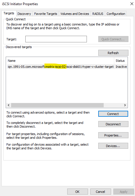
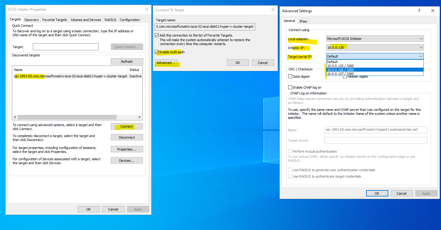
After selecting the iSCSI target server within the discovered targets and clicking on the Connect button, first the Connect to Target dialog is opened as shown below.
Here we need to check Enable multi-path and then clicking on Advanced.
On the Advanced Settings dialog we finally configure the multi-path connection from the Hyper-V Host to the iSCSI Target server and its disk.
For the local adapter its always Microsoft iSCSI initiator, the initiator IP is the source IP (our Hyper-V Host), in my lab environment I will just have a host management NIC and IP address to select here besides NICs for the VM virtual networks, in production environments you will select here also a dedicated iSCSI traffic NIC like for the iSCSI target server shown previously.
Finally we need to select the target portal IP (iSCSI target server), here I will select the first dedicated iSCSI traffic NIC/IP address from the iSCSI target server which is 10.0.0.126 and click on OK.
On the Targets tab we can see that the target is now in status connected as shown below. But so far by just using one path (the first dedicated NIC and IP).
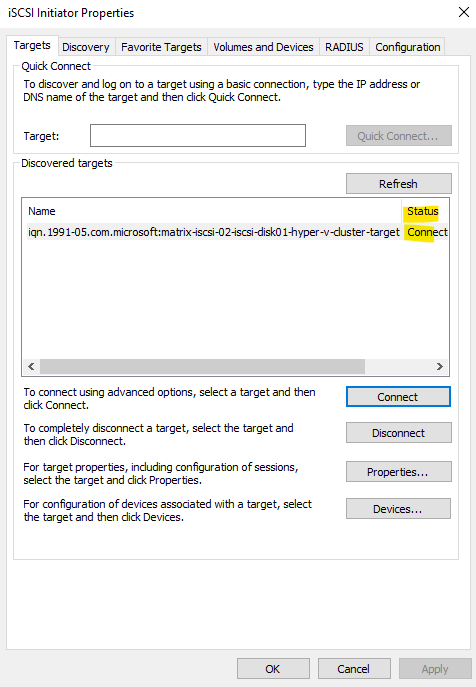
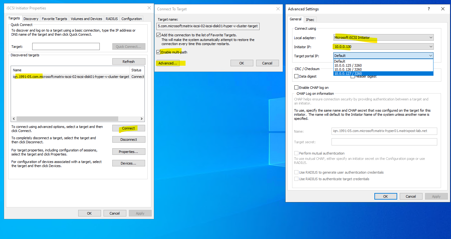
To connect the Hyper-V Host also with the second dedicated iSCSI Target server NIC/IP address, we need to click again on the Connect button for our selected discovered target.
Then same as above besides that we now for the target portal IP select the iSCSI target server’s second dedicated ISCSI traffic NIC/IP address, in my case 10.0.0.127.
As mentioned usually in product environments, you will also select here a different Initiator NIC/IP address.
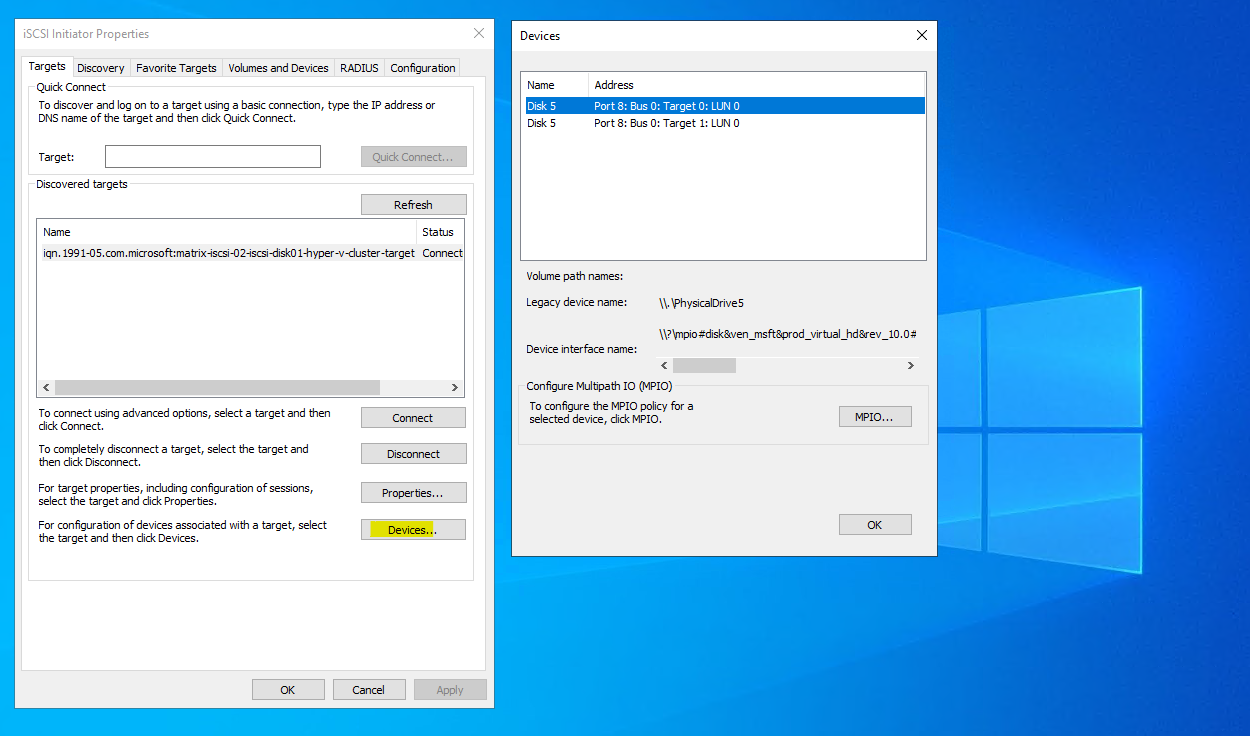
When now clicking on the Devices … button within the Targets tab, we can see two disks with the same name Disk 5.
After connecting to the target twice using different target portal IPs, the same iSCSI disk appears multiple times with different Target IDs, each representing a separate path.
Although Disk Management shows these as separate entries without MPIO enabled, they point to the same underlying LUN accessed through different network paths. With MPIO enabled, Windows combines these paths into a single logical disk, providing redundancy and improved throughput.
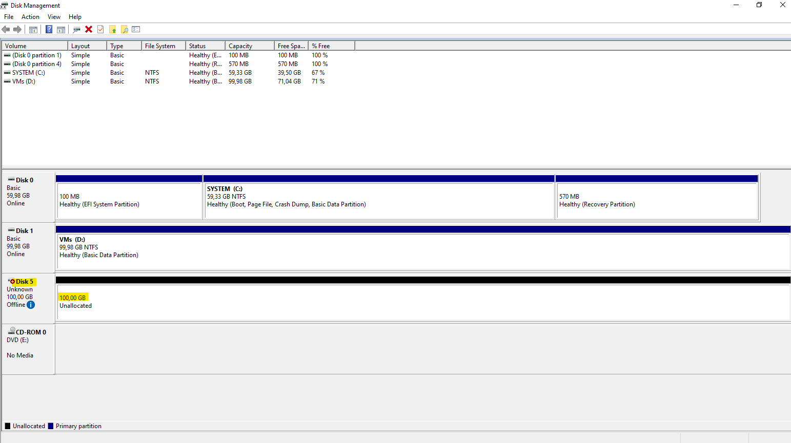
In the Disk Management tool on the Hyper-V host the disk is shown up correctly just once as MPIO is enabled
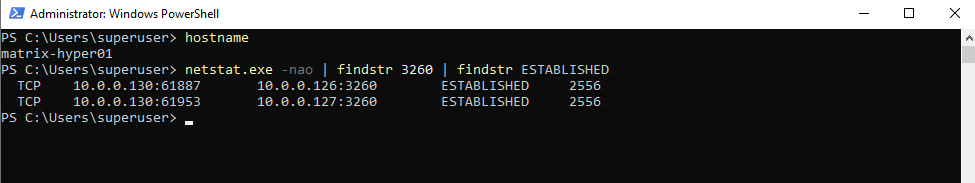
By running the netstat command as shown below, we can see that the Hyper-V Host has established an iSCSI target connection to both IP addresses as desired and configured above.
PS> netstat.exe -nao | findstr 3260 | findstr ESTABLISHED
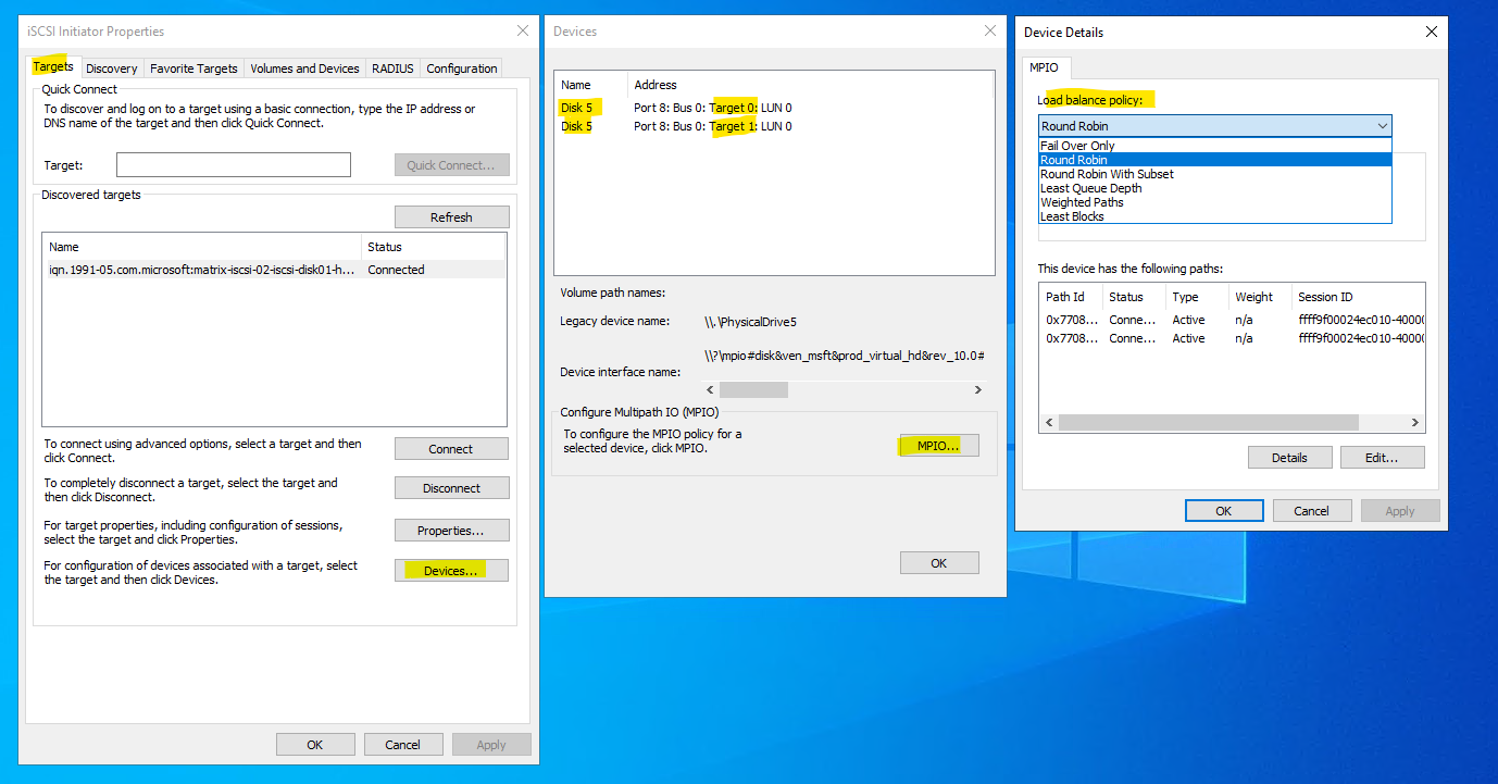
In the MPIO dialog of the iSCSI Initiator as shown below, the load balance policy defines how I/O is distributed across the available paths to the same disk.
The list below shows all detected paths; in this case, both entries are Connected and Active, confirming that multipath connectivity is working as intended.
The selected policy determines whether traffic is balanced across paths or prefers specific ones based on performance or priority.
Round Robin is the most commonly used and recommended policy for iSCSI MPIO in Hyper-V environments unless there is a specific reason to prefer another mode.
Load balance policy differences:
- Round Robin (default) – I/O is evenly distributed across all active paths
- Round Robin with Subset – Uses a preferred set of paths, others are standby
- Least Queue Depth – Sends I/O to the path with the fewest outstanding requests
- Weighted Paths – Distributes traffic based on manually assigned weights
- Least Blocks – Chooses the path that has processed the fewest blocks
The same procedure is now repeated on the second Hyper-V host. By connecting to the iSCSI target using the same target portal IPs and enabling multipath, the shared disk is presented through multiple paths on both cluster nodes.
Once completed, both hosts have identical access to the iSCSI LUN, which is a prerequisite for using it as a Cluster Shared Volume.
Initializing and Preparing the iSCSI Disk for the Cluster
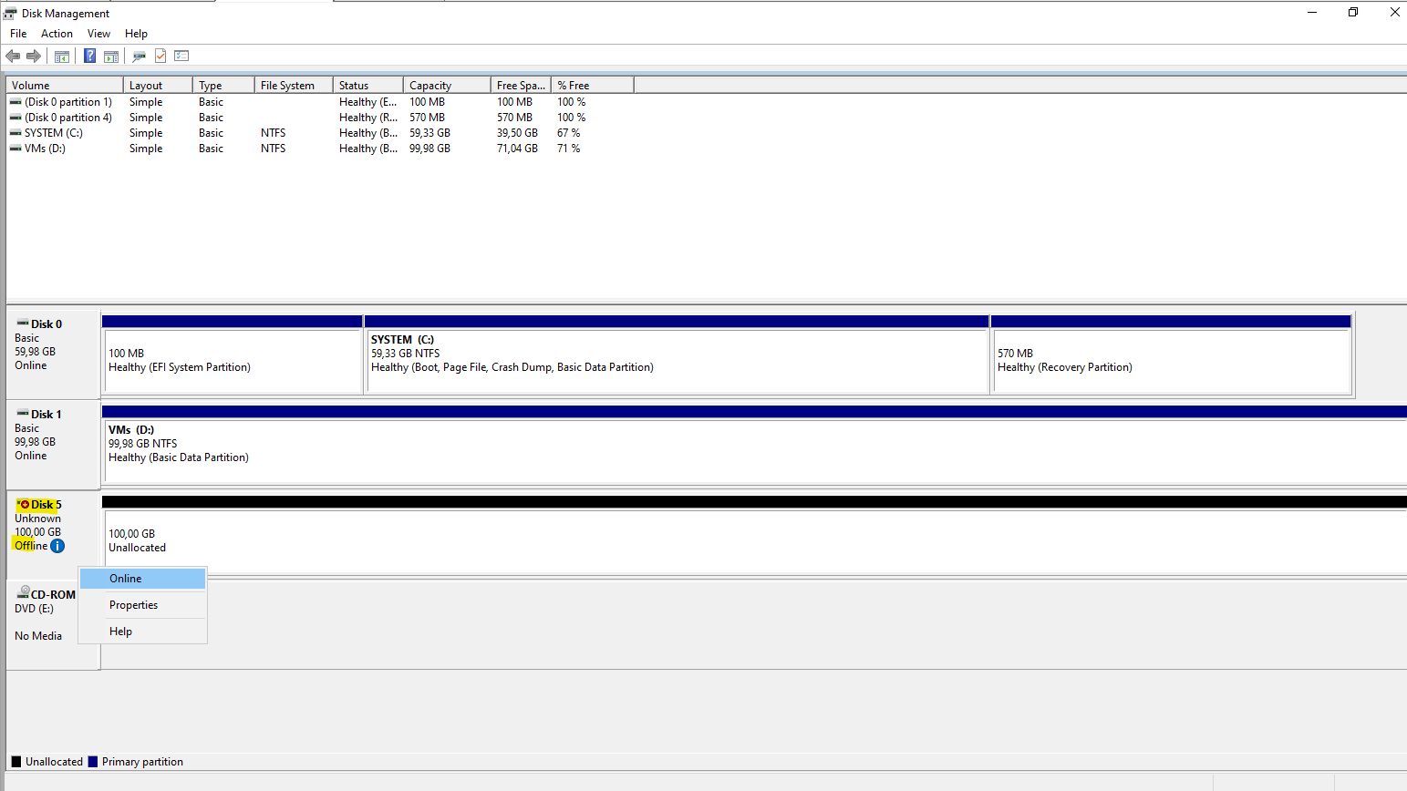
Once the iSCSI disk is connected to both Hyper-V hosts, it must first be taken online and initialized on one node.
Initializing the disk only creates the partition table, which allows Failover Cluster Manager to detect and add the disk as available storage, but it is not yet usable as a CSV.
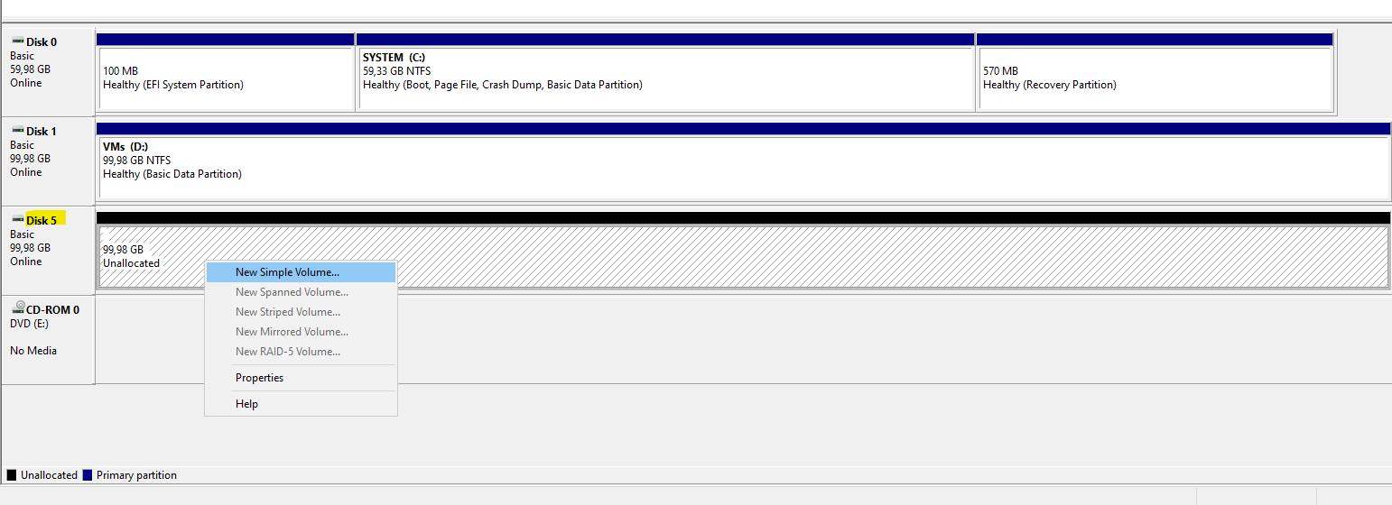
To convert the disk into a Cluster Shared Volume, a suitable partition and file system must be created first after initialization and before adding it to the cluster.
First bring the disk Online.
Initialize the disk.
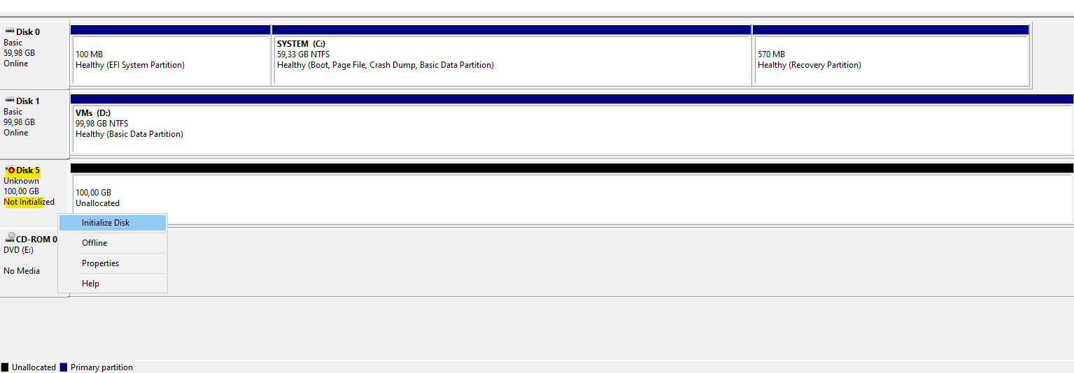
Before the iSCSI disk can be used, it must be initialized in Disk Management. Initializing the disk writes the partition table (MBR or GPT).

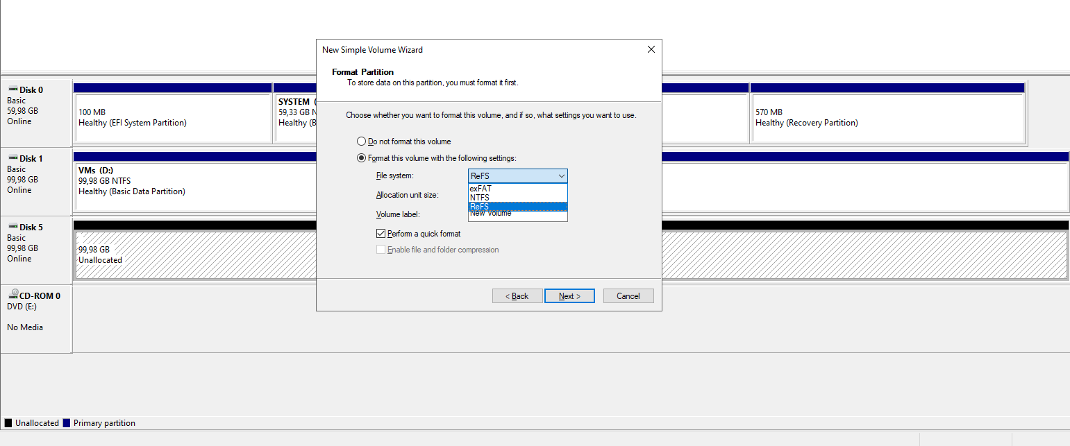
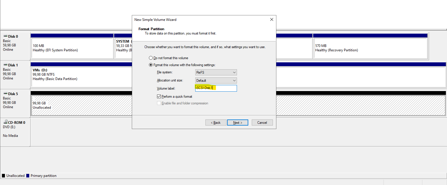
Create a new volume on the disk.
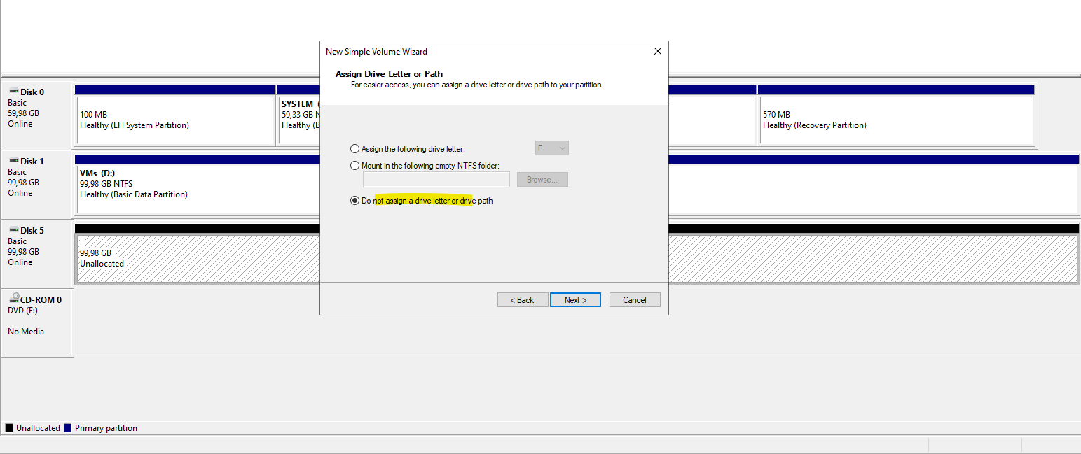
A drive letter is optional and can be skipped, as the volume will later be accessed through the CSV path under
C:\ClusterStorage
For Hyper-V workloads, ReFS is generally the better choice.
For Cluster Shared Volumes hosting Hyper-V virtual machines, ReFS is the preferred file system due to its performance optimizations and resiliency features.
NTFS remains a valid option for compatibility reasons, but ReFS is the better default choice for modern Hyper-V clusters.
Adding the iSCSI Disk to the Cluster and Converting It to a CSV
After the iSCSI disk has been initialized and formatted, it can be added to the failover cluster as shared storage.
Once the disk is registered with the cluster, it is assigned as a Cluster Shared Volume (CSV) to make it accessible from all Hyper-V hosts simultaneously.
This final step completes the integration of the iSCSI-backed disk into the Hyper-V cluster.
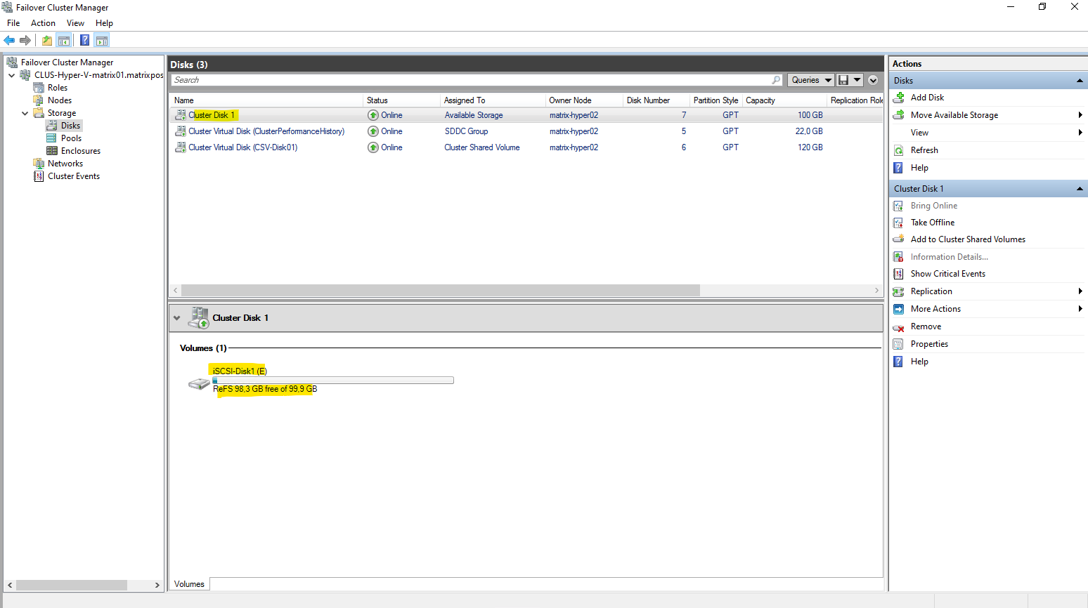
In the failover cluster manager, click under Storage -> Disks on Add Disk as shown below, select our iSCSI disk and click on OK.
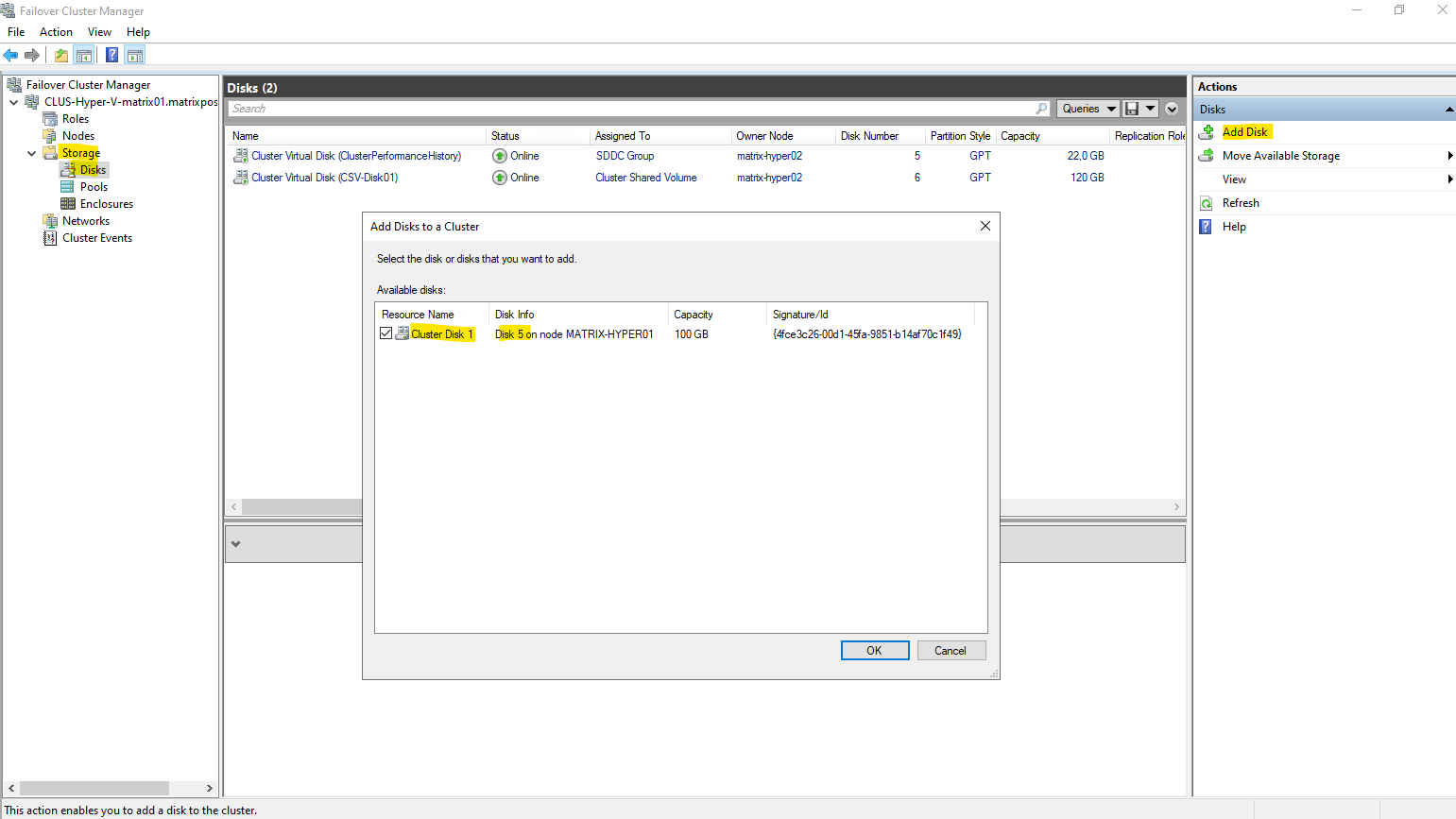
After adding the disk to Failover Cluster Manager, it is automatically assigned a generic name such as “Cluster Disk 1”. This is the default naming convention used by the cluster for newly added shared disks.
The disk can be renamed at any time to a more descriptive name before or after converting it into a Cluster Shared Volume (CSV).
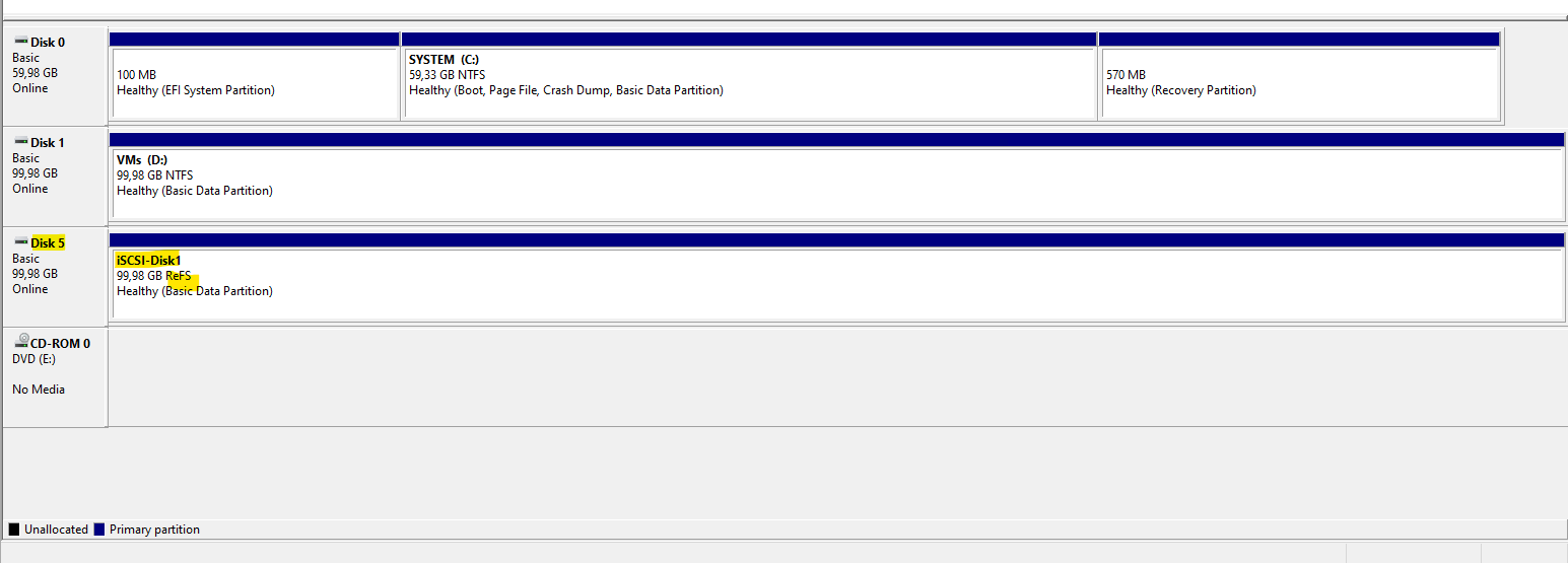
So far the file system label is shown as ReFS below. This will change later after adding the disk to Clustered Shared Volumes as shown below.
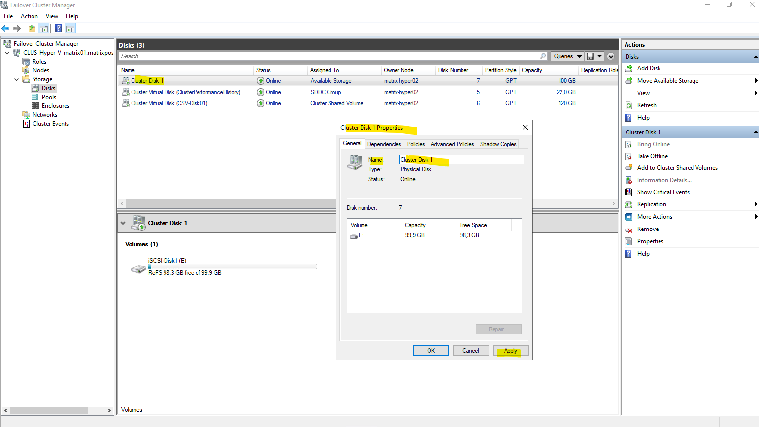
Right click on the disk and select properties. Then you can rename the disk in the Name field below.
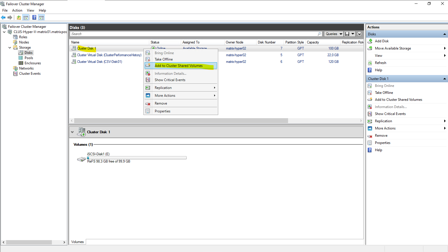
To add the disk to Clustered Shared Volumes, right click on the disk and select Add to Clustered Shared Volumes.
When a volume is added as a Cluster Shared Volume, the file system label changes from ReFS to CSVFS.
CSVFS (Cluster Shared Volume File System) is not a separate file system, but a clustered access layer that sits on top of the underlying ReFS volume.
This layer enables simultaneous read/write access from all cluster nodes while preserving ReFS on disk.
CSVFS is ReFS with cluster semantics.
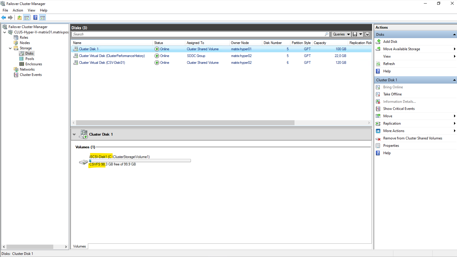
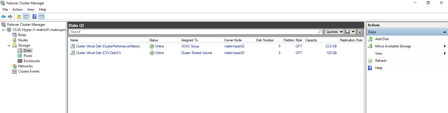
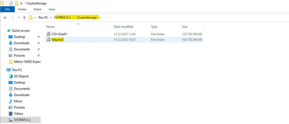
After being added as a Cluster Shared Volume, the new virtual disk is automatically mounted under
C:\ClusterStorage\Volume1on every node in the cluster as already mentioned.This unified path provides consistent access to the volume regardless of which Hyper-V host is currently running a virtual machine.
All VM files stored in this directory are therefore available cluster-wide and can move seamlessly between nodes.
The CSV-Disk01 volume is from S2D as shown in my previous post here.
With the Cluster Shared Volume in place, our Hyper-V Cluster is now fully prepared to host virtual machines.
From this point on, Hyper-V VMs can be created directly on the new CSV, benefiting from shared, resilient storage across all cluster nodes.
Any VM placed here can be moved freely between hosts without requiring changes to its underlying storage.
More about creating virtual machines in the cluster and store its files on the CSV, you will see in my previous post below. The only difference here is, that the CSV is stored on S2D and not on a iSCSI disk.
Links
Cluster Shared Volumes overview
https://learn.microsoft.com/en-us/windows-server/failover-clustering/failover-cluster-csvsManage Cluster Shared Volumes
https://learn.microsoft.com/en-us/windows-server/failover-clustering/failover-cluster-manage-cluster-shared-volumesiSCSI Target Server overview
https://learn.microsoft.com/en-us/windows-server/storage/iscsi/iscsi-target-server