How Multicast Traffic Works in VMware vSphere – Testing VSS (Basic Multicast Filtering) vs VDS (IGMP/MLD Snooping) with Video Streaming – Part 2
In Part 1, we built the multicast lab environment and explored multicast communication within a single VLAN, including IGMP, IGMP Snooping, and multicast filtering on both physical and virtual switches.
In this part, we’ll extend the lab by configuring multicast routing across VLANs with pfSense, allowing multicast streams to traverse Layer 3 boundaries while maintaining proper group membership.
- Multicast Across VLANs with pfSense and IGMP
- Moving the Receiver to a Different VLAN
- Configure pfSense as the Multicast Router
- Testing Multicast Routing Across VLANs
- Inside the IGMP Proxy (pfSense): From Membership Report to Multicast Forwarding
- Understanding Common Multicast Addresses and Default Group Memberships
- Troubleshooting
- Links
Multicast Across VLANs with pfSense and IGMP
In the Part 1, I demonstrated how to configure multicast streaming within a single VLAN using FFmpeg, VLC, IGMP, and IGMP Snooping. While this is sufficient for many scenarios, production networks often separate multicast sources and receivers into different VLANs for security, scalability, or administrative reasons.
In this part, we’ll take the next step by configuring pfSense as a multicast router, allowing multicast traffic to be forwarded between VLANs. Along the way, we’ll explore how multicast routing differs from traditional IP routing, how IGMP and multicast routing protocols work together, and how to verify each step using Wireshark and practical lab tests.
By the end of this guide, multicast clients located in a different VLAN from the FFmpeg streaming server will be able to join the multicast group and receive the stream, while multicast traffic continues to be forwarded only where it is actually needed.
Moving the Receiver to a Different VLAN
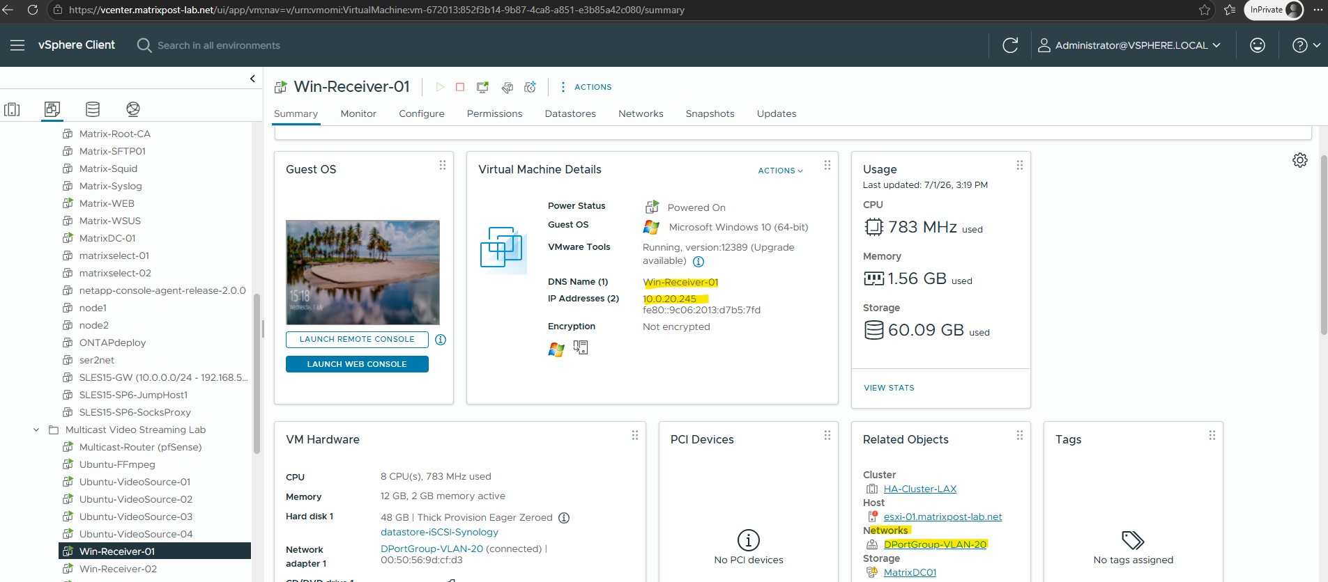
To demonstrate multicast routing, the multicast receiver must no longer reside in the same Layer 2 broadcast domain as the FFmpeg streaming server. Therefore, the receiver VM is moved to a different VLAN by assigning it to another vSphere port group connected to the corresponding VLAN.
At this point, the multicast stream is no longer expected to work. Although the receiver can still send IGMP Membership Reports, standard IP routers do not forward multicast traffic by default. In the following sections, we’ll configure pfSense to route multicast traffic between the two VLANs and verify each step along the way.
Configure pfSense as the Multicast Router
To forward multicast traffic between different VLANs, we first need a multicast-capable router. In this lab, pfSense fulfills this role by connecting both VLANs through dedicated interfaces.
At this stage, we only configure the network interfaces and basic Layer 3 connectivity.
Multicast routing itself will be enabled later by configuring the IGMP Proxy service.
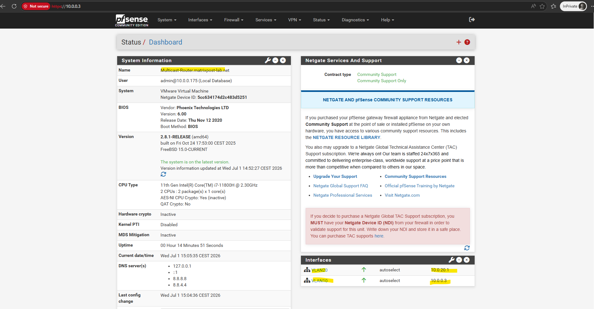
Basic Setup
For this lab, pfSense is equipped with two virtual network adapters, one connected to VLAN 10 (10.0.0.3/24) and the other to VLAN 20 (10.0.20.1/24).
This allows pfSense to act as the Layer 3 gateway between both networks and later forward multicast traffic between them.
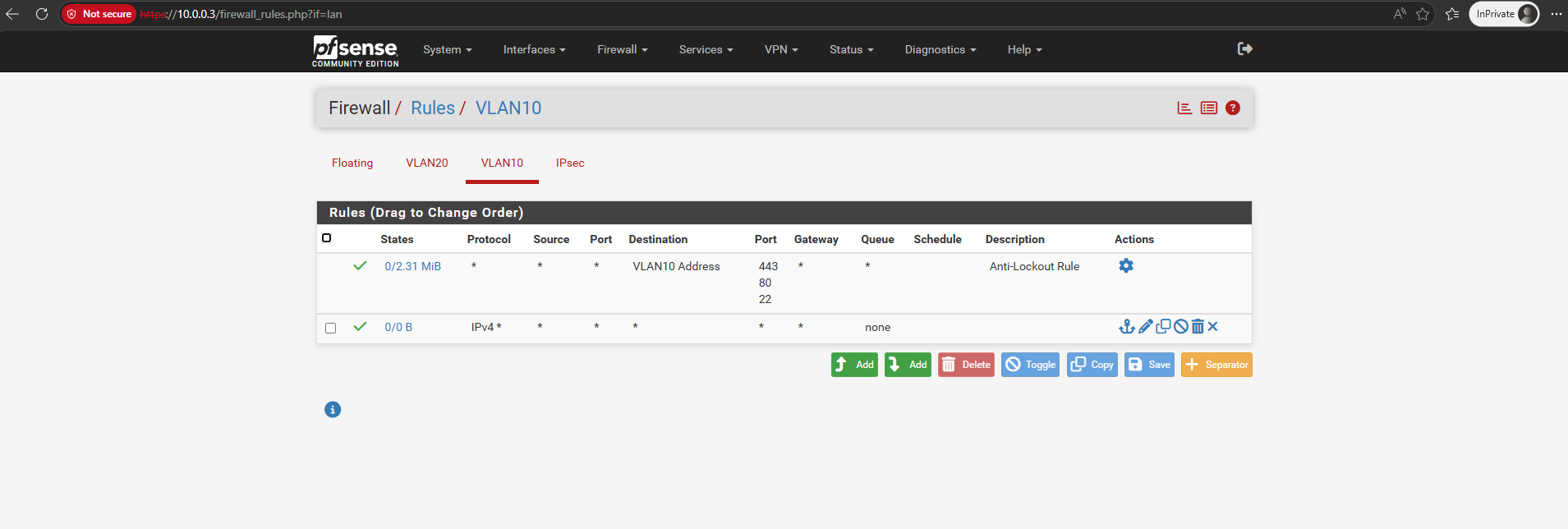
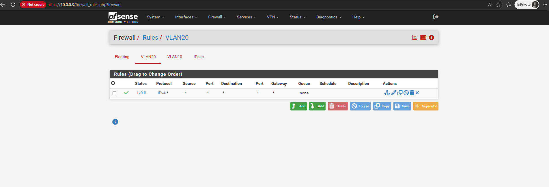
To avoid introducing unnecessary complexity, firewall rules on both the VLAN 10 and VLAN 20 interfaces are configured to allow all traffic. This ensures that any connectivity issues encountered during the lab are related to the multicast configuration rather than packet filtering.
The VLC receiver VM I already moved into the VLAN 20 and adjusted its IP address to 10.0.20.245, the FFmpeg streaming server still resides in VLAN 10 and IP address 10.0.0.240.
For the default gateway the new multicast router (pfSense) and its VLAN 20 NIC and IP address is set.
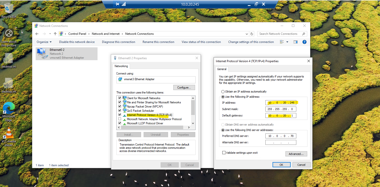
The routing between both VLANs already worked.
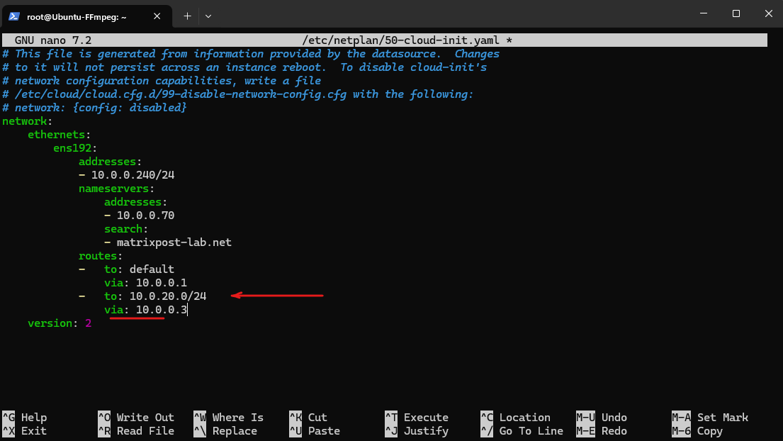
Only the new route to the new VLAN 20 and its subnet 10.0.20.0/24 I need to add on the FFmpeg streaming server
In addition to the default gateway, Netplan allows you to configure static routes to reach remote networks through specific next-hop routers.
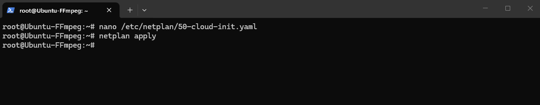
root@Ubuntu-FFmpeg:~# nano /etc/netplan/50-cloud-init.yaml
On Ubuntu with Netplan, after editing the YAML file, apply the new configuration with:
# netplan apply
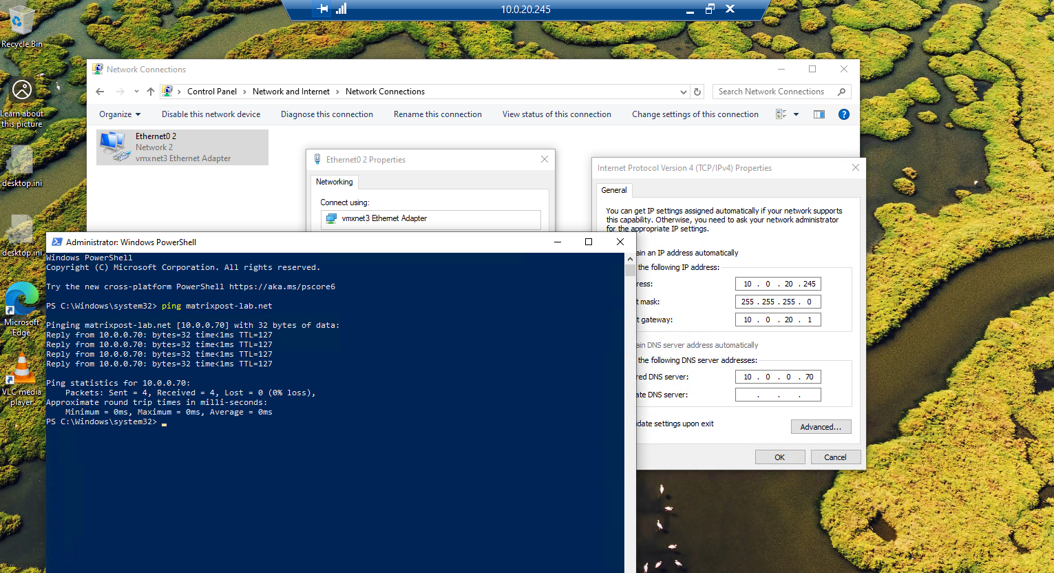
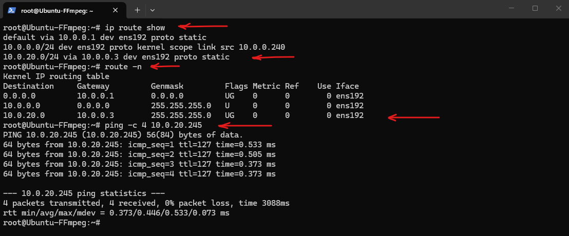
After adding the required route for VLAN 20 where the VLC receiver VM runs, the FFmpeg server can successfully reach the receiver VM (10.0.20.245) through pfSense, confirming that basic Layer 3 connectivity between both VLANs is working as expected.
At this stage, however, only unicast communication is functional, multicast traffic will still not be forwarded until multicast routing is configured in the following sections.
root@Ubuntu-FFmpeg:~# ip route show
root@Ubuntu-FFmpeg:~# route -n
root@Ubuntu-FFmpeg:~# ping -c 4 10.0.20.245
More about Netplan and network configuration on Ubuntu you will find here.
Finally the topology will looks like below:
VLAN 10 (10.0.0.0/24)
-----------------------------
Ubuntu-FFmpeg          10.0.0.240
pfSense VLAN 10 NIC    10.0.0.3

                    │
               Multicast Router
                 (IGMP Proxy)
                    │

VLAN 20 (10.0.20.0/24)
-----------------------------
pfSense VLAN 20 NIC    10.0.20.1
Win-Receiver           10.0.20.245
Configure IGMP Proxy
Although basic Layer 3 connectivity between both VLANs is now working, the multicast stream still cannot reach receivers located in another subnet.
Unlike unicast traffic, multicast packets are not forwarded by traditional IP routing. To enable multicast communication across VLANs, pfSense must be configured to act as a multicast router by enabling the IGMP Proxy service.
The IGMP Proxy service in pfSense also provides the IGMP Querier functionality required to maintain multicast group memberships. Unlike the vSphere Distributed Switch (VDS) shown in Part 1, which sends General Queries from
0.0.0.0, pfSense uses the IP address of its interface as shown below because it acts as a Layer 3 multicast router.
The IGMP Proxy listens for IGMP Membership Reports (Join messages) from receivers on downstream networks and forwards them upstream towards the multicast source.
As long as at least one receiver remains subscribed, pfSense continues forwarding the multicast traffic between the VLANs. Once the last receiver leaves the multicast group, the proxy removes the membership and multicast forwarding stops automatically.
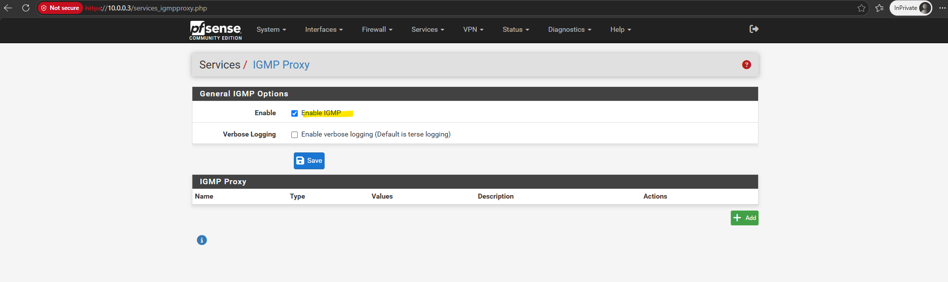
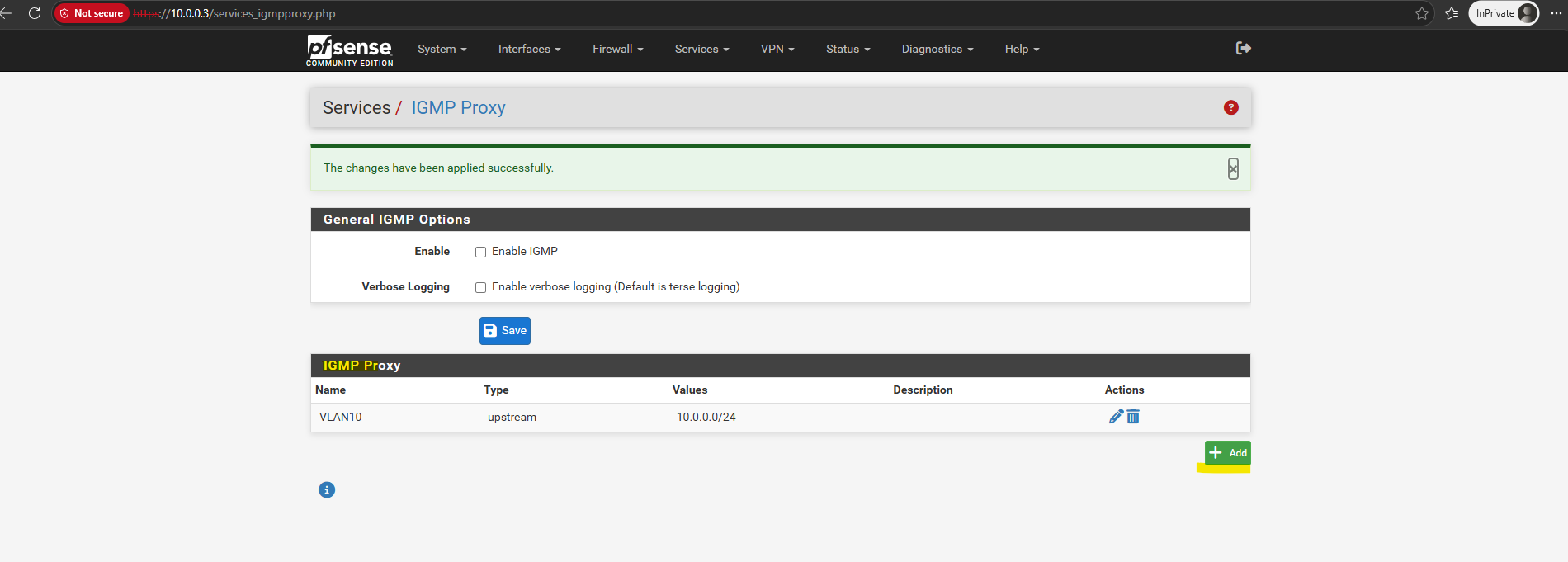
Navigate to Services ➜ IGMP Proxy.
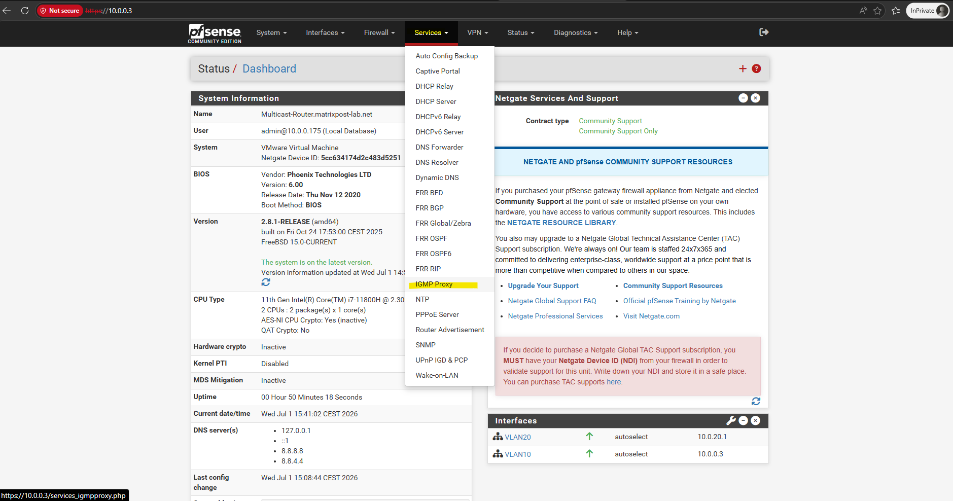
Check Enable IGMP Proxy.
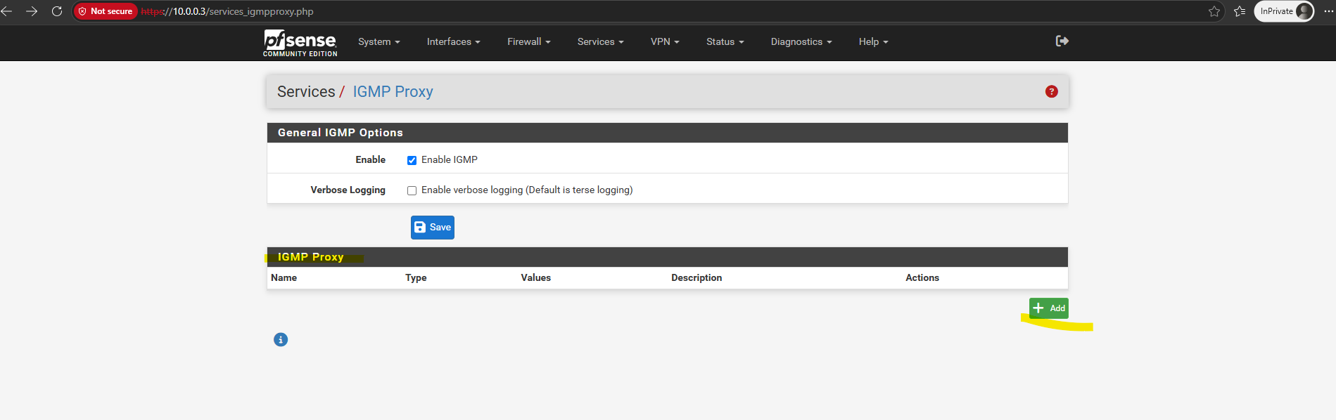
Next in the IGMP Proxy section click on + Add to add an upstream interface.
Under Interfaces, configure:
- Upstream Interface → VLAN 10 (
10.0.0.3) - Subnet →
10.0.0.0/24
and click on Save.

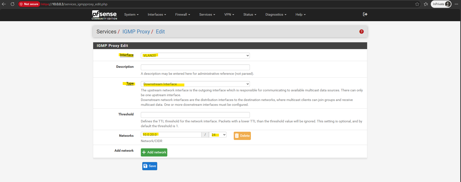
Add a second interface:
- Downstream Interface → VLAN 20 (
10.0.20.1) - Subnet →
10.0.20.0/24
For the type this time we need to select Downstream Interface.
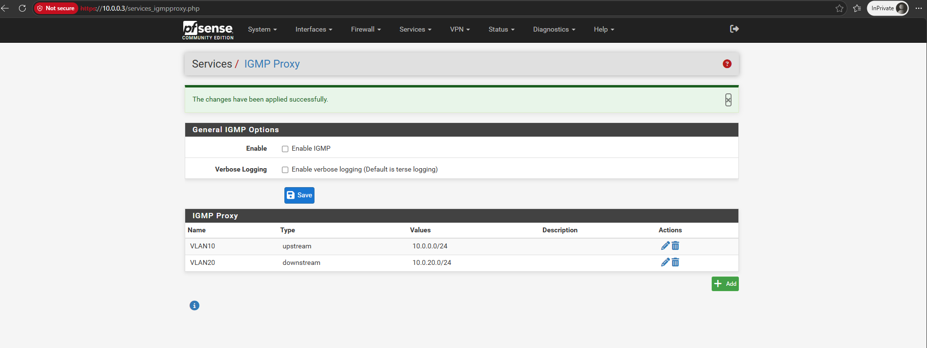
The
upstreaminterface always points toward the multicast source, while one or moredownstreaminterfaces represent the networks where multicast receivers are located.When a receiver joins a multicast group, pfSense forwards the corresponding IGMP Membership Report from the
downstreaminterface to the upstream network, allowing the multicast stream to be delivered across VLAN boundaries.
After configuring the upstream and downstream interfaces for the IGMP Proxy, make sure to also review the firewall rule on the receiver-side interface.
On pfSense, the Allow IP Options setting must also be enabled on the VLAN 20 interface rule so that the receiver’s IGMP Membership Reports can pass through the firewall and be forwarded upstream.
The Allow IP Options setting must be enabled on the VLAN 20 interface (downstream interface) firewall rule, as this is where the receiver’s IGMP Membership Reports, including the IPv4 Router Alert option, first enter the pfSense firewall.
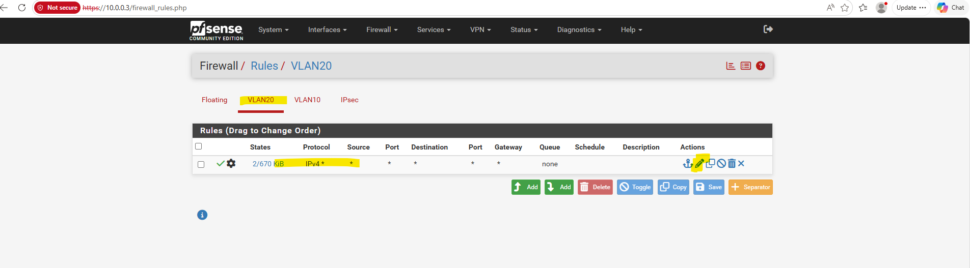
Navigate to Firewall -> Rules -> VLAN 20 (downstream interface) and click on Edit.
Even a wide-open “Allow All” rule in pfSense will silently drop packets with IP options unless you explicitly tell that specific rule to permit them. Because an IGMP Join packet contains the “Router Alert” IP option, pfSense strips it at the firewall boundary, preventing it from ever reaching the IGMP proxy daemon to be forwarded to VLAN 10 (upstream interface).
Scroll down to the Extra Options section.
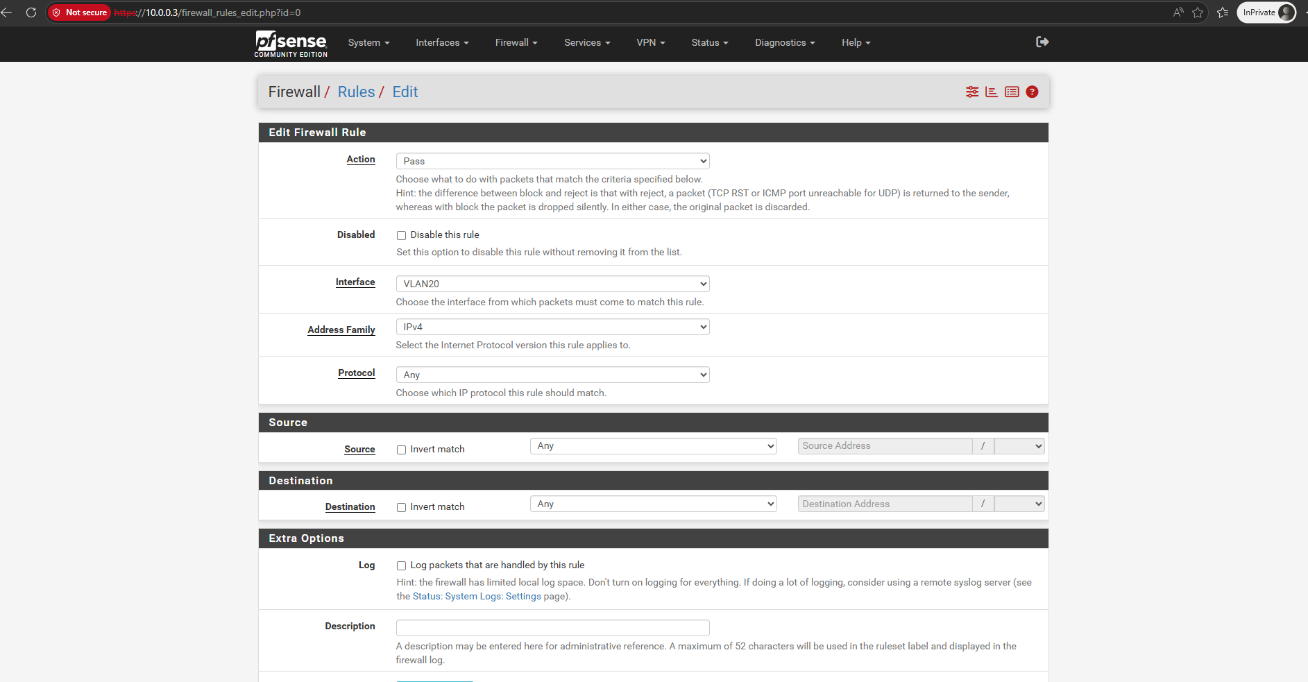
Click on Display Advanced.
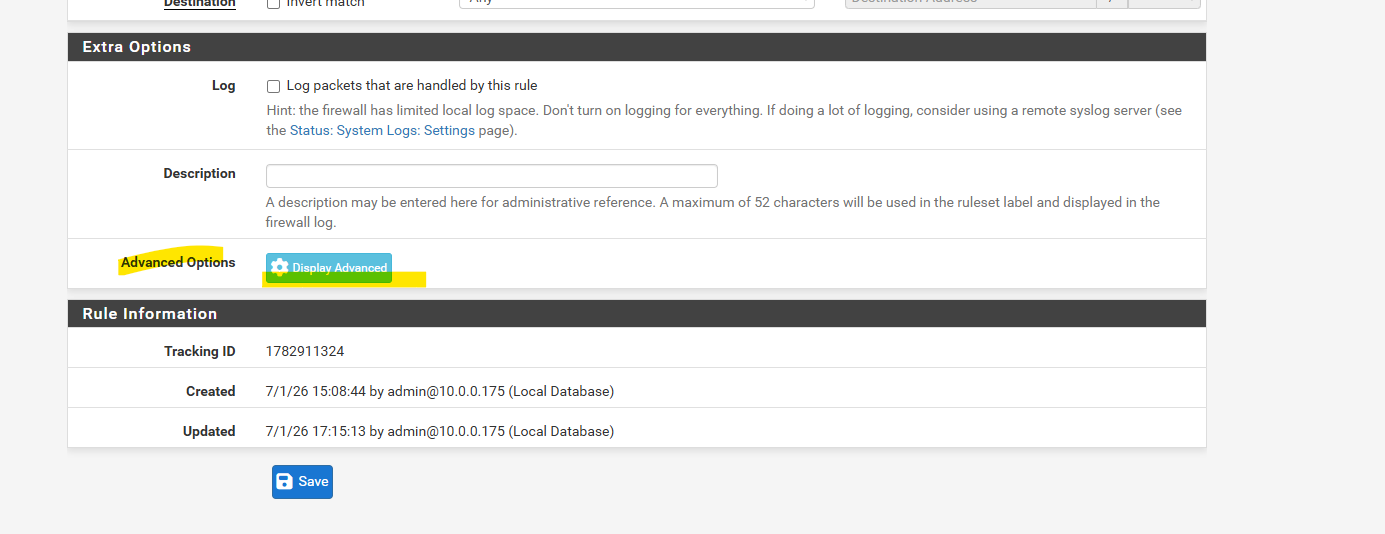
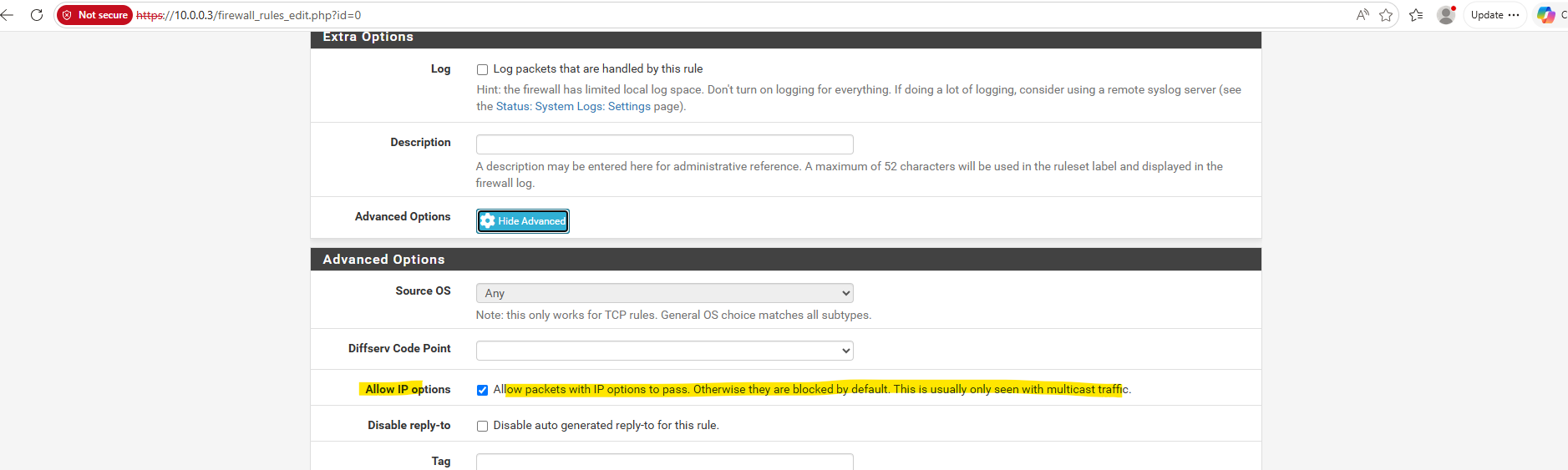
Enable and check Allow IP options.
“Allow packets with IP options to pass. Otherwise they are blocked by default. This is usually only seen with multicast traffic.”
The Router Alert option is a special IPv4 header option that instructs routers to inspect a packet instead of simply forwarding it.
When the receiver’s IGMP Membership Report reaches the downstream interface, pfSense intercepts it, processes it locally using the IGMP Proxy, and then forwards a corresponding Membership Report upstream to establish the multicast forwarding state.
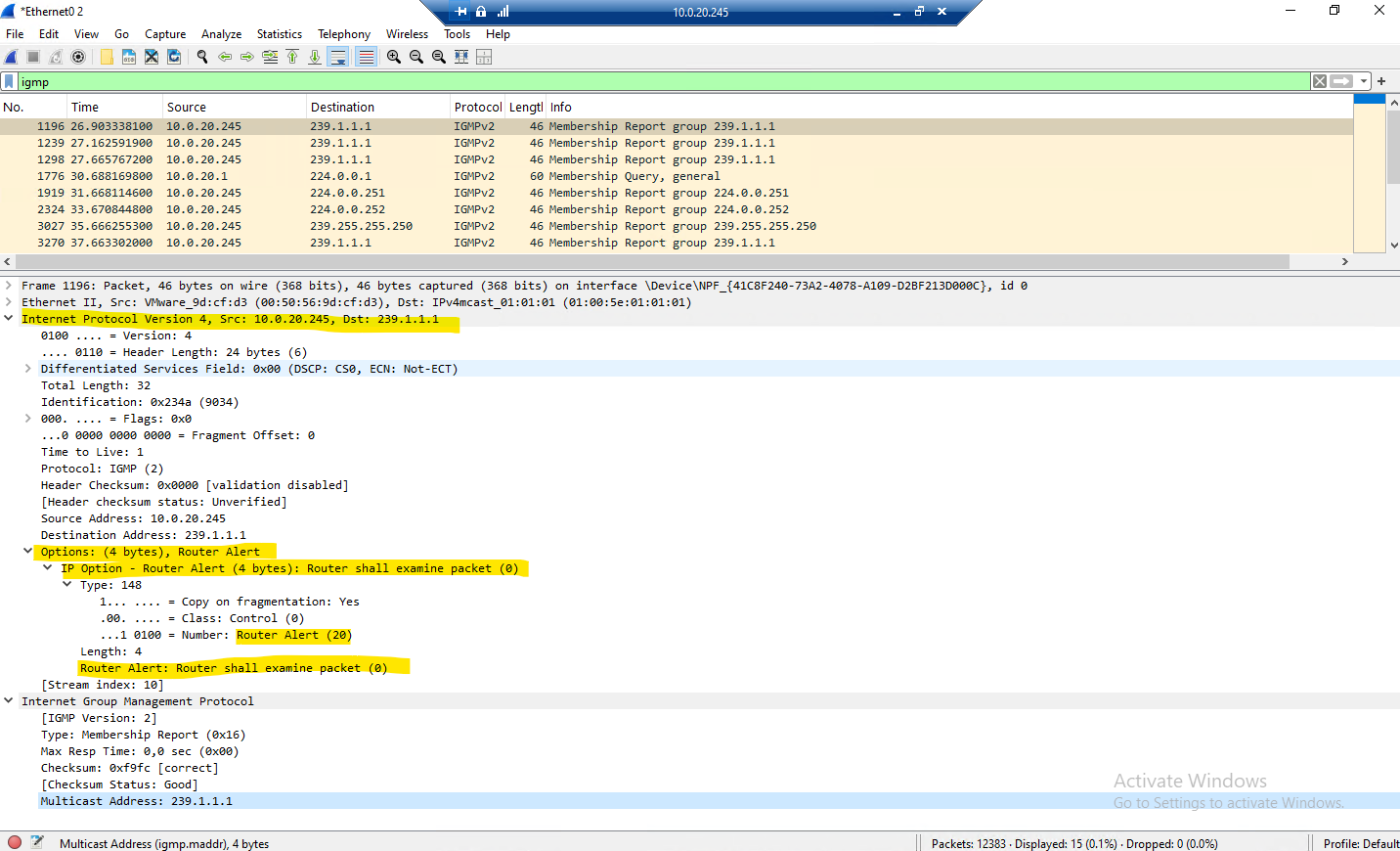
Expanding the IPv4 header of the IGMP Membership Report in Wireshark reveals the
Router AlertIP option. This special IPv4 header option instructs routers to inspect the packet locally rather than simply forwarding it.Both the IGMP General Query and the IGMP Membership Report contain the
Router AlertIPv4 option. This is expected, as both packets carry multicast control information that must be inspected by multicast routers (or an IGMP Proxy) rather than being treated as ordinary IP packets.Outside of multicast, the Router Alert option is used only by a small number of control protocols, most notably RSVP for Quality of Service (QoS). It is rarely seen in ordinary network traffic, which is why many firewalls block IPv4 packets containing IP options by default.
In this lab, pfSense intercepts the Membership Report arriving on the downstream interface, processes it with the IGMP Proxy, and generates a corresponding IGMP Membership Report on the upstream interface to request the multicast stream from the source network.
For the VLAN 10 rule (upstream interface), you do not need to enable it:
- The Receiver (VLAN 20): Sends an IGMP Join packet to the pfSense gateway. This packet contains the “Router Alert” IP option, so the VLAN 20 firewall rule must explicitly allow it to pass into the firewall engine.
- The pfSense IGMP Proxy Daemon: Once the firewall lets the packet pass, the internal IGMP proxy processes it. The proxy then generates its own fresh IGMP Join packet locally from the firewall itself and injects it directly out of the VLAN 10 interface.
- The Sender (VLAN 10): Because pfSense’s firewall rules only inspect incoming traffic on an interface, the locally-generated IGMP Join exiting the VLAN 10 interface is allowed out automatically. Furthermore, the actual multicast video stream coming back into VLAN 10 from our FFmpeg server consists of standard UDP packets, these do not contain IP options, so our standard “Allow All” rule on VLAN 10 will handle them perfectly.
Regarding the above mentioned second step with “The proxy then generates its own fresh IGMP Join packet locally from the firewall itself and injects it directly out of the VLAN 10 interface.”:
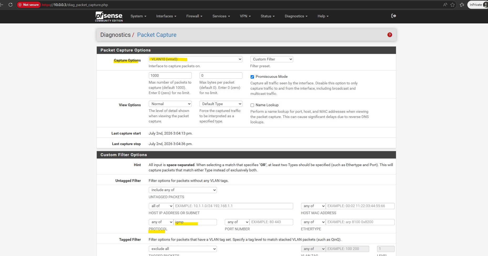
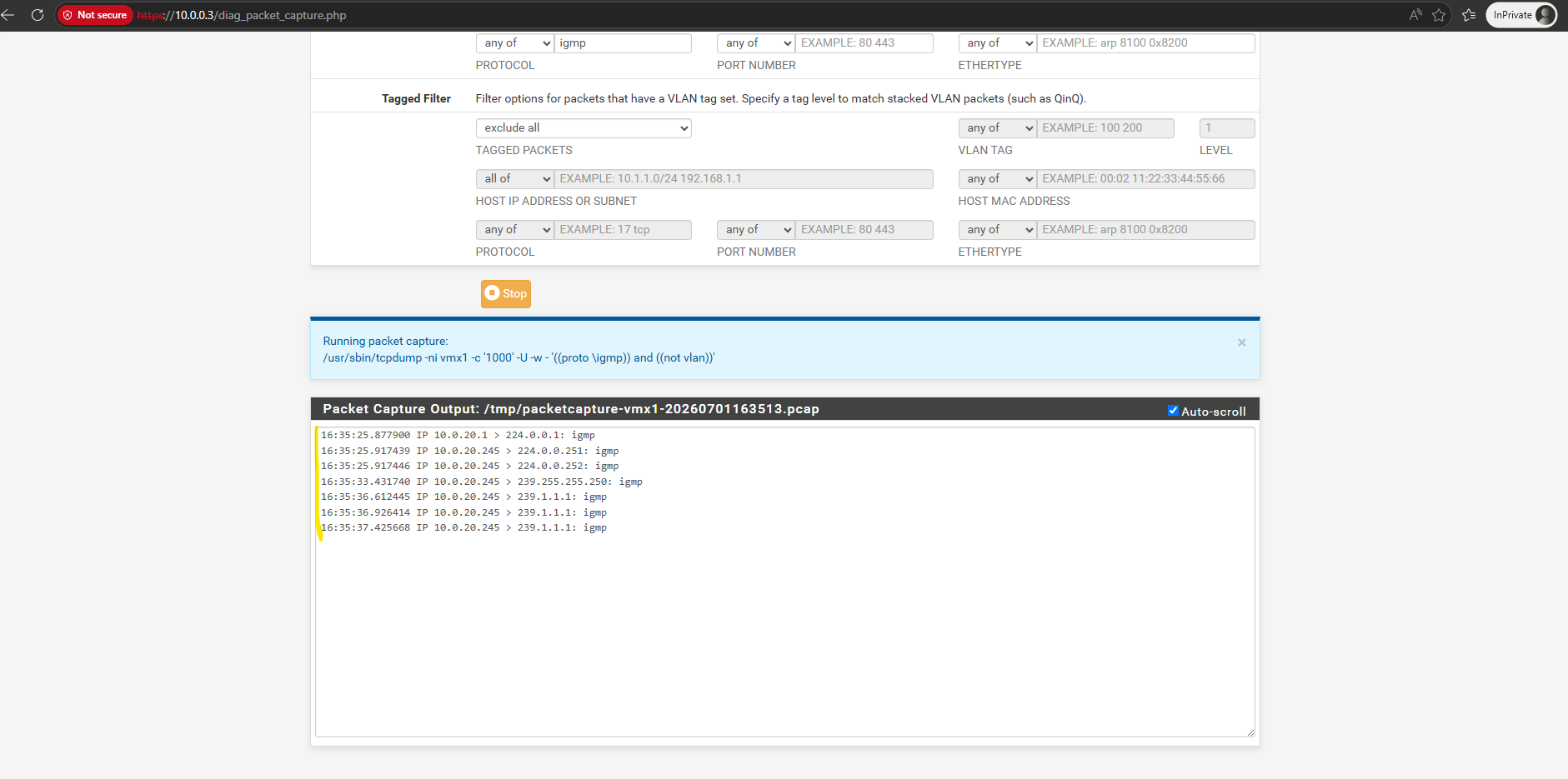
This packet capture on the upstream VLAN 10 interface confirms that the pfSense IGMP Proxy is working successfully. After intercepting the client’s request on VLAN 20, the firewall (
10.0.0.3) acts as a proxy client, broadcasting an IGMPv3 Membership Report to the standard224.0.0.22multicast address to request the239.1.1.1stream from the upstream network.Notice that the first packet originates from
0.0.0.0and is sent to224.0.0.1(All Hosts).As already shown in Part 1, this is the periodic IGMP General Query sent by the vSphere Distributed Switch (VDS) acting as the IGMP Querier for the VLAN.
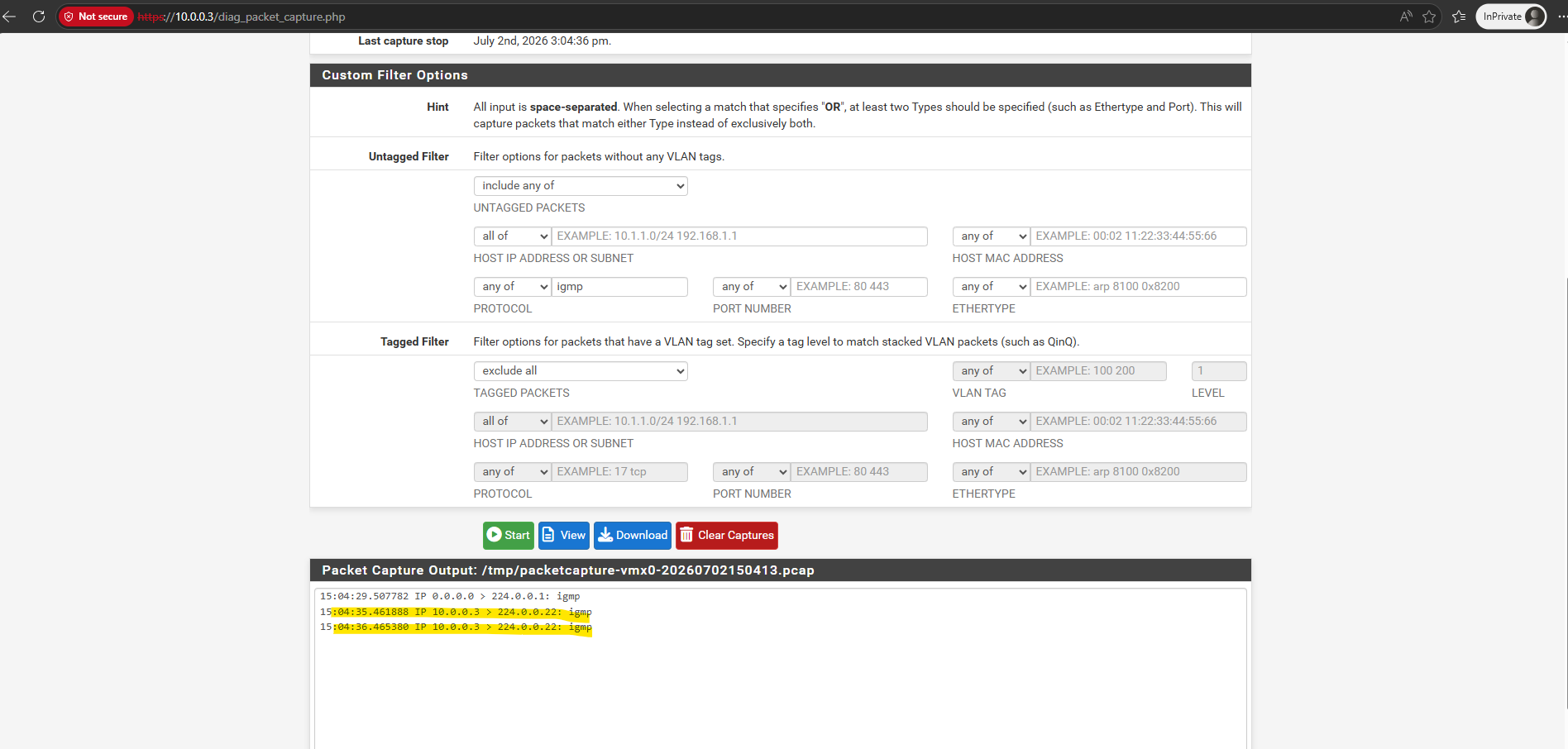
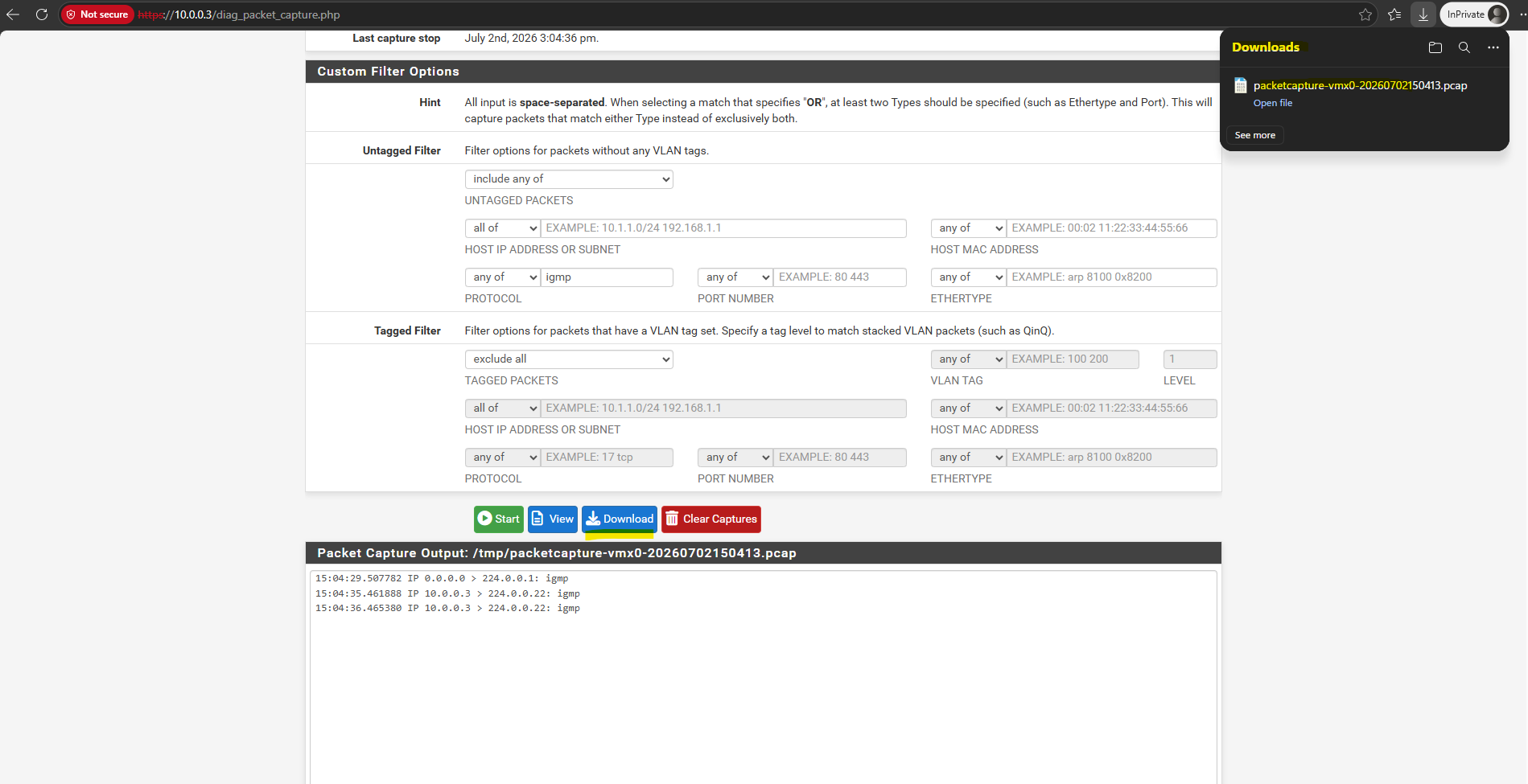
By downloading this capture file directly from pfSense, we can open it in Wireshark to deeply analyze the underlying IGMP protocol structure.
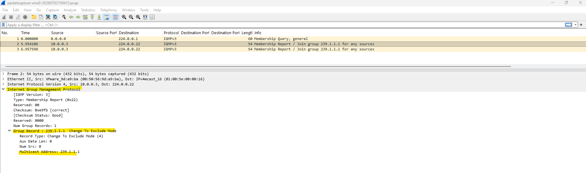
Expanding the IGMPv3 packet details explicitly shows the “Group Record” containing the
239.1.1.1multicast address, confirming that the firewall is successfully requesting that specific stream on behalf of our receiver.The downloaded capture also contains in the first packet the periodic IGMP Membership Query (General) sent by the IGMP Querier to the
224.0.0.1 (All Hosts)multicast group. As shown in Part 1.
The diagram below illustrates how IGMP Proxy forwards IGMP Membership Reports from the downstream network towards the multicast source.
Once at least one receiver has joined the multicast group, pfSense begins forwarding the multicast stream back from the upstream interface to the downstream network.
                IGMP Join
                     ▲
                     │
Receiver (VLAN 20) ──┘
        │
        ▼
+----------------------+
|       pfSense        |
|     IGMP Proxy       |
+----------------------+
        │
        │ forwards Join
        ▼
Sender (VLAN 10)

Multicast stream
239.1.1.1
        ▲
        │
        └────────────── forwarded back to VLAN 20
With pfSense and the IGMP Proxy now fully configured, everything is in place to route multicast traffic between both VLANs.
We can now verify that receivers located in VLAN 20 can successfully join the multicast group and receive the stream from the FFmpeg server in VLAN 10.
Testing Multicast Routing Across VLANs
Now it’s time to put the configuration to the test. We’ll verify the complete multicast communication path, from the receiver joining the multicast group, through IGMP Proxy forwarding the membership reports, to the successful delivery of the multicast stream across the VLAN boundary.
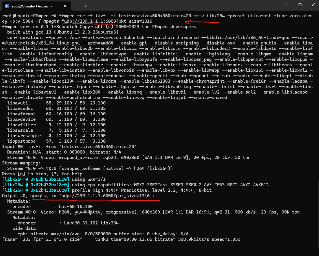
To verify multicast routing across the VLAN boundary, the FFmpeg server below generates a simple test pattern and continuously streams it as an MPEG Transport Stream (MPEG-TS) to the multicast group 239.1.1.1 on UDP port 6000. Once a receiver joins the multicast group, the stream should be forwarded by pfSense to the destination VLAN.
root@Ubuntu-FFmpeg:~# ffmpeg -re -f lavfi -i testsrc=size=640x360:rate=20 -c:v libx264 -preset ultrafast -tune zerolatency -b:v 500k -f mpegts "udp://239.1.1.1:6000?pkt_size=1316"
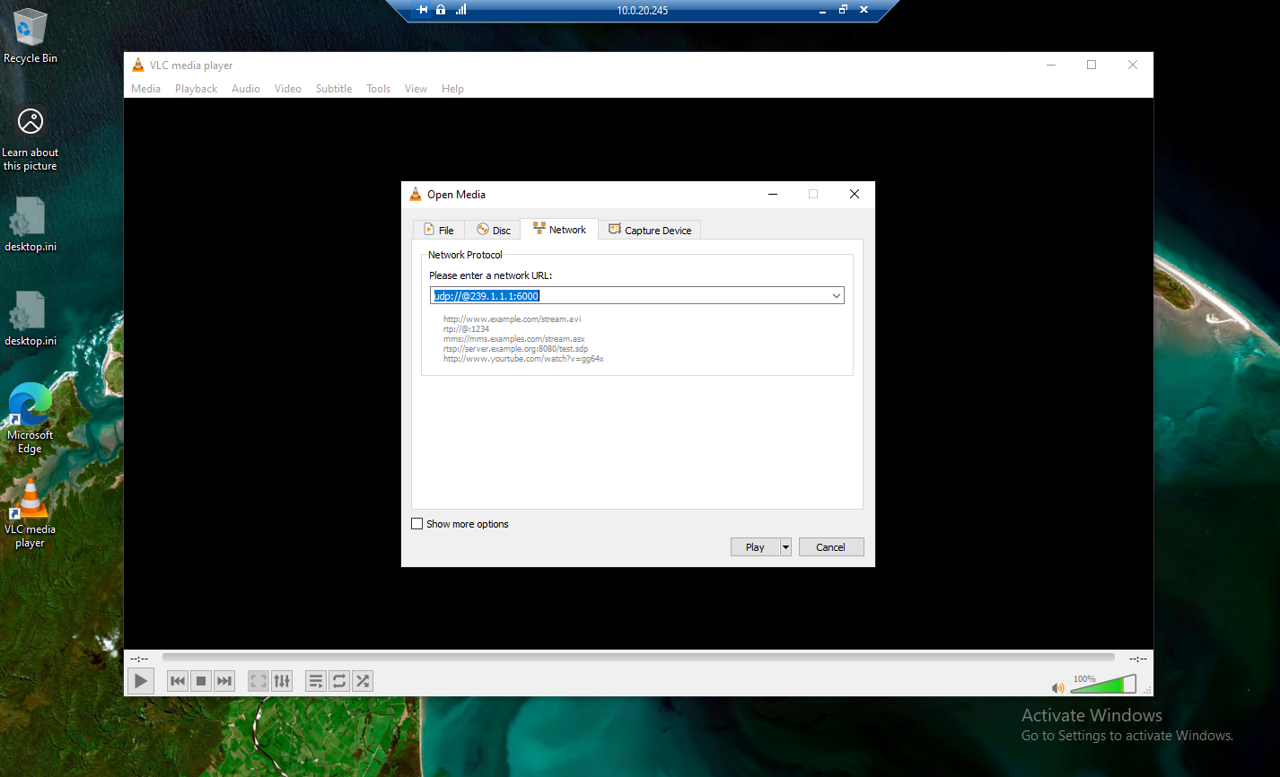
To receive the multicast stream on our receiver clients (Windows 10 VMs), we open like before the VLC Media Player and select Media > Open Network Stream. Then enter the multicast address in the format udp://@239.1.1.1:6000 and click Play to join the multicast group and start receiving the stream.
Once playback starts, VLC displays the live synthetic test pattern. At the beginning of the playback, you can also see the configured multicast UDP URL (udp://@239.1.1.1:6000) before it automatically disappears.
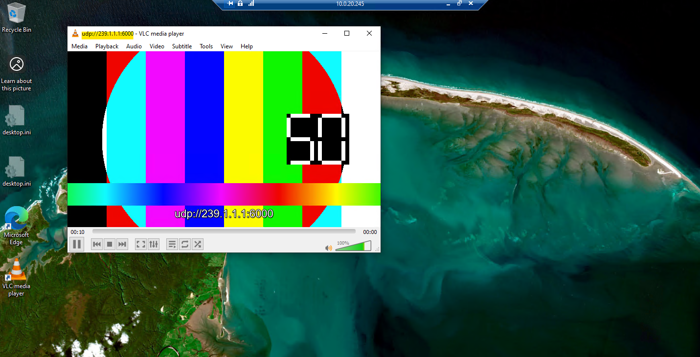
With the routing logic verified and the pfSense IP options enabled, the video stream now flows seamlessly from VLAN 10 to the receiver on VLAN 20.
Because the underlying Layer 2 mechanics of the VSS and VDS remain unchanged from Part 1, there is no need to repeat those switch-level packet filtering tests.
This part successfully proves that with proper IGMP proxying in place, multicast streams can reliably traverse Layer 3 boundaries across any enterprise network infrastructure.
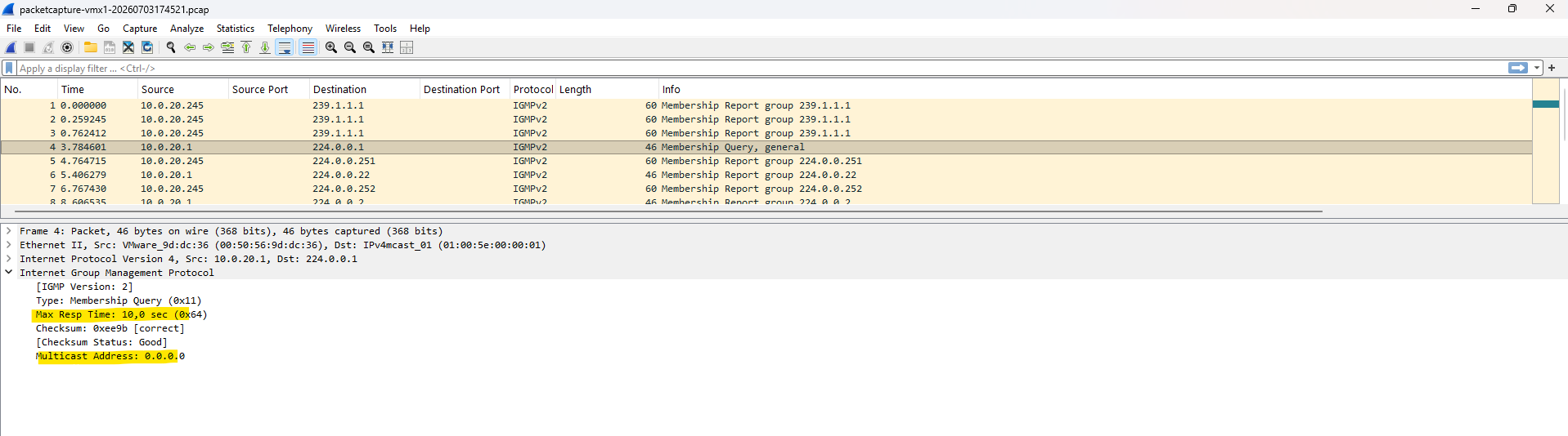
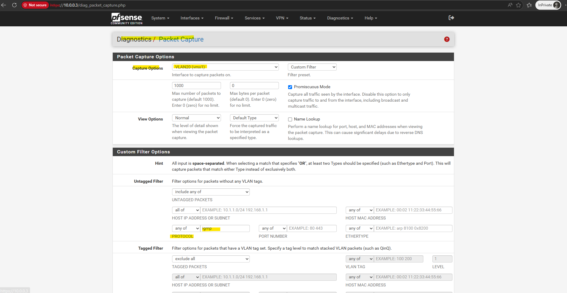
After starting the multicast stream, the packet capture on the pfSense VLAN 20 interface shows both the periodic IGMP General Queries (10.0.20.1 → 224.0.0.1) generated by pfSense, which provides the IGMP Querier functionality through its IGMP Proxy service, and the corresponding IGMP Membership Reports sent by the receiver.
Notice that although the packet is sent to the
224.0.0.1 (All Hosts)multicast address, the Multicast Address field inside the IGMP packet is0.0.0.0.This identifies the packet as a General Query, requesting all multicast-capable hosts to report every multicast group they are currently subscribed to, rather than querying a specific multicast group.
An interesting observation is that the vSphere Distributed Switch (VDS) uses a Max Response Time of 1 second, whereas pfSense uses the more common default of 10 seconds. The Max Response Time defines the maximum time receivers may wait before responding to an IGMP General Query with a Membership Report. A shorter value results in faster membership updates, while a longer value reduces the likelihood of many hosts responding simultaneously.
Inside the IGMP Proxy (pfSense): From Membership Report to Multicast Forwarding
Packet captures provide an excellent view of the IGMP messages exchanged between hosts and the multicast router. However, they don’t reveal the internal decisions made by the IGMP Proxy itself.
By starting igmpproxy in verbose debug mode (igmpproxy -d -vv), we can follow the complete multicast routing process, from receiving Membership Reports and creating multicast routes to programming the kernel’s Multicast Forwarding Cache (MFC) and forwarding multicast traffic to downstream receivers.
After starting igmpproxy in verbose debug mode by using the -d -vv parameters, the daemon first parses its configuration file, initializes the configured upstream and downstream interfaces, and builds its internal virtual interface (VIF) table.
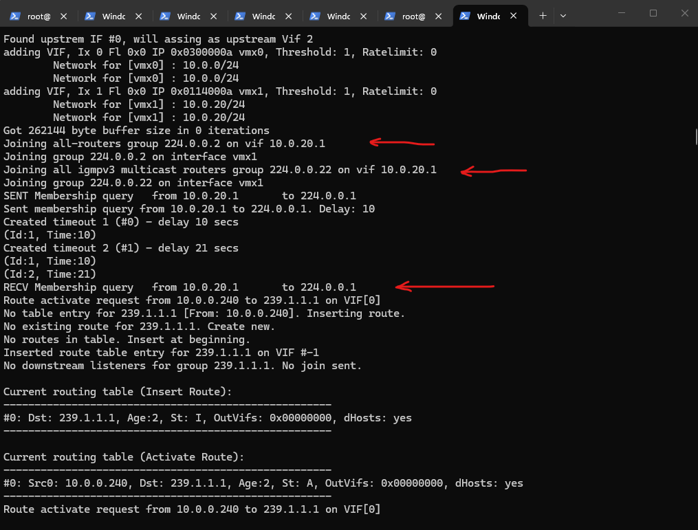
During this phase, it verifies the configured networks, joins the required multicast router groups (224.0.0.2 and 224.0.0.22) on the downstream interface, and starts the built-in IGMP Querier by immediately sending the first IGMP General Query to 224.0.0.1 (All Hosts). At this point, the proxy is fully initialized and ready to receive Membership Reports from downstream clients and establish multicast forwarding as receivers join multicast groups
Since
igmpproxyis normally started by pfSense as a background service, it must first be stopped before launching it manually in verbose debug mode. The existing instance already owns the multicast routing resources, so only one instance can run at a time. After stopping the service withpkill igmpproxy, it can be started interactively by usingigmpproxycommand below to observe its internal processing in real time.
[2.8.1-RELEASE][admin@Multicast-Router.matrixpost-lab.net]/: pkill igmpproxy
[2.8.1-RELEASE][admin@Multicast-Router.matrixpost-lab.net]/: igmpproxy -d -vv /var/etc/igmpproxy.conf
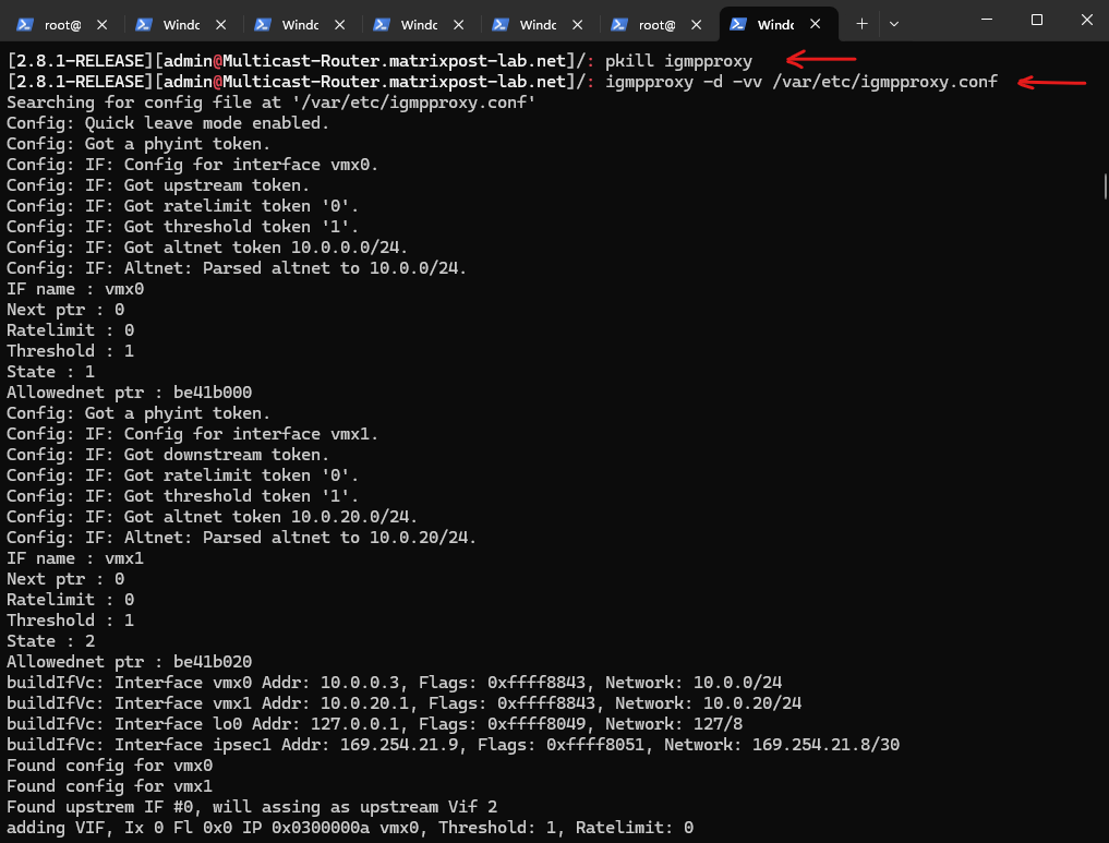
Unlike 224.0.0.1 (All Hosts), which every multicast-capable host joins automatically, 224.0.0.2 is joined only by multicast routers (or devices acting as multicast routers).
Joining all-routers group 224.0.0.2 → the firewall (pfSense) announces itself as a multicast router on the downstream network
Joining all igmpv3 multicast routers group 224.0.0.22
SENT Membership query from 10.0.20.1 to 224.0.0.1
The First Receiver Joins the Multicast Group
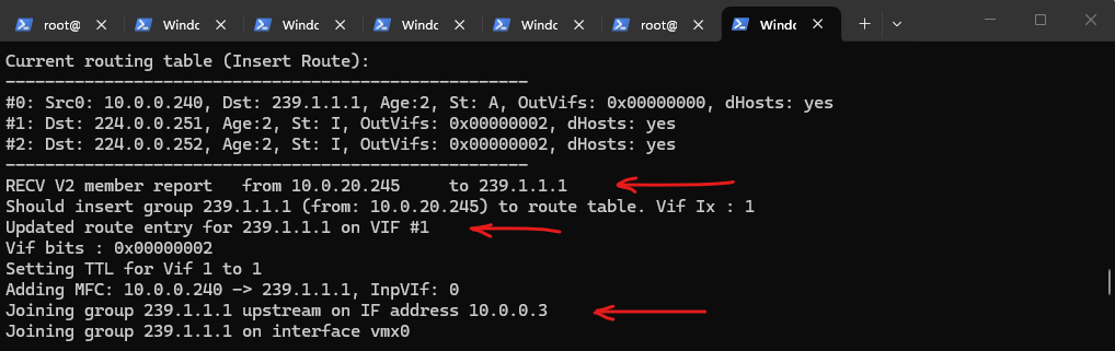
Once the receiver starts playing the multicast stream, it responds to the periodic IGMP General Query by sending an IGMP Membership Report for the requested multicast group.
Upon receiving this report, the IGMP Proxy recognizes that a downstream host is interested in the stream, updates its internal routing table, and joins the same multicast group on the upstream interface.
This effectively links the downstream receiver to the upstream multicast source and prepares the kernel to forward multicast traffic between both interfaces.
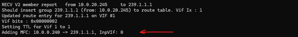
RECV V2 member report from 10.0.20.245 to 239.1.1.1
Updated route entry for 239.1.1.1 on VIF #1
Joining group 239.1.1.1 upstream on IF address 10.0.0.3
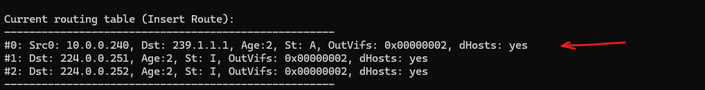
Updating the Internal Routing Table
The routing table maintained by the IGMP Proxy distinguishes between active multicast routes and passive group memberships.
The entry for 239.1.1.1 includes both the multicast source (10.0.0.240) and the destination group because multicast traffic is actively flowing.
In contrast, the entries for
224.0.0.251(mDNS) and224.0.0.252(LLMNR) contain only the multicast group and are marked as inactive (I). These entries exist because the downstream receiver automatically joined these well-known multicast groups, even though no multicast source is currently transmitting traffic for them.
Programming the Multicast Forwarding Cache (MFC)
The Adding MFC message indicates that the IGMP Proxy has programmed the kernel’s Multicast Forwarding Cache (MFC).
This creates the forwarding rule for the (Source, Group) pair (10.0.0.240 → 239.1.1.1), enabling the kernel to efficiently forward subsequent multicast packets from the upstream interface to all downstream interfaces with subscribed receivers.
Adding MFC:
10.0.0.240 -> 239.1.1.1
InpVIf: 0
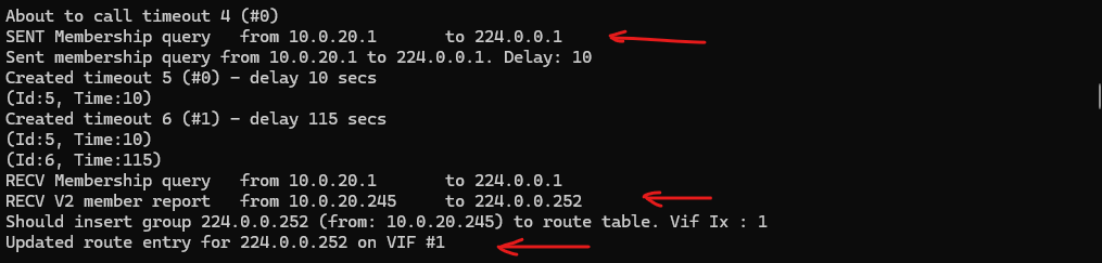
Refreshing Memberships
Once the multicast forwarding state has been established, the IGMP Querier periodically sends IGMP General Queries (10.0.20.1 → 224.0.0.1) to verify that receivers are still interested in the multicast groups they previously joined.
The subsequent Membership Reports refresh the existing routing entries, such as 224.0.0.251 (mDNS) shown here, allowing the IGMP Proxy to maintain multicast forwarding without recreating the routes.
SENT Membership query
...
RECV V2 member report
Updated route entry
IGMP Proxy vs. IGMP Snooping: Who Maintains Which Membership Table?
One important distinction is that the IGMP Proxy is not responsible for maintaining the IGMP Snooping tables used by switches. Instead, the same IGMP Membership Reports are processed independently by multiple devices throughout the network, each maintaining its own membership information for a different purpose.
The IGMP Proxy on pfSense maintains multicast routing state at Layer 3, determining which multicast streams should be requested from the upstream network and forwarded between VLANs. In contrast, physical switches and a vSphere Distributed Switch (VDS) with IGMP Snooping enabled maintain Layer 2 IGMP Snooping tables, mapping multicast groups to switch ports so that multicast traffic is delivered only to receivers that have joined the corresponding multicast group.
| Component | Maintains | Purpose |
|---|---|---|
| pfSense (IGMP Proxy) | Multicast routing table + MFC | Layer 3 multicast routing between VLANs |
| Physical Switch (IGMP Snooping) | IGMP Snooping table | Layer 2 forwarding to physical switch ports |
| vSphere VDS (IGMP Snooping) | IGMP Snooping table | Layer 2 forwarding to virtual switch ports |
Although all three components observe the same IGMP Membership Reports, each builds and maintains its own membership table independently. This separation of responsibilities enables efficient multicast forwarding at both Layer 2 and Layer 3 while avoiding unnecessary multicast flooding.
Understanding Common Multicast Addresses and Default Group Memberships
Throughout this post, we’ve encountered several multicast addresses serving different purposes, from 224.0.0.1 used by the IGMP Querier to 224.0.0.22 carrying IGMPv3 Membership Reports, and 239.1.1.1 used by our multicast video stream.
In addition, operating systems such as Windows and Linux automatically join a number of well-known multicast groups during startup, even before any multicast application is running.
The following table summarizes the most common multicast addresses you’ll encounter in this lab and explains when and why they are used.
| Multicast Group | Purpose | Joined Automatically? |
|---|---|---|
| 224.0.0.1 | All Hosts | ✅ All multicast-capable hosts |
| 224.0.0.2 | All Routers | ✅ Multicast routers only |
| 224.0.0.22 | IGMPv3 Membership Reports | ❌ Destination address only |
| 224.0.0.251 | mDNS | Depends on service |
| 224.0.0.252 | LLMNR | Windows |
| 239.255.255.250 | SSDP / UPnP | Depends on service |
| 239.1.1.1 | Application multicast | Only after an application joins |
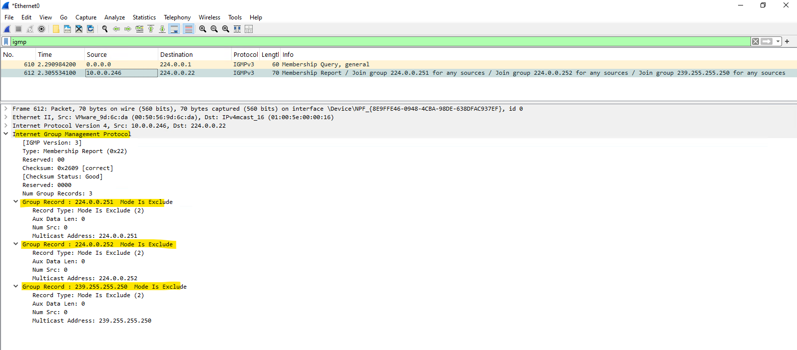
As summarized in the previous table, Windows automatically joins several well-known multicast groups before any multicast application is started.
The following Wireshark capture, taken on one of the receiver VMs before VLC begins playing the multicast stream, shows an IGMPv3 Membership Report advertising memberships for groups such as 224.0.0.251 (mDNS), 224.0.0.252 (LLMNR), and 239.255.255.250 (SSDP/UPnP).
The first packet in the capture is the periodic IGMP General Query (0.0.0.0 → 224.0.0.1) generated by the vSphere Distributed Switch (VDS) acting as the IGMP Querier, as discussed in the previous section.
Notice that the application-specific multicast group
239.1.1.1is not yet present, as it is joined only after VLC starts receiving the multicast stream.
About Multicast DNS (mDNS) you can read my following post.
Although LLMNR supports both IPv4 and IPv6, the packet captures in this lab show the IPv4 multicast group 224.0.0.252, as the multicast streaming environment is based entirely on IPv4.
One additional note: Microsoft has been moving away from LLMNR in recent Windows versions due to security concerns (e.g., spoofing attacks), and many organizations disable it via Group Policy in enterprise environments. So while you’ll often see
224.0.0.252in lab or default installations, it may be absent in hardened corporate networks.
More about and how to disable LLMNR you will also find in my following post.
The Simple Service Discovery Protocol (SSDP) is part of the Universal Plug and Play (UPnP) framework and is used to automatically discover devices and services on the local network, such as printers, media servers, IP cameras, routers, and smart TVs.
Windows joins the 239.255.255.250 multicast group by default to participate in SSDP-based service discovery.
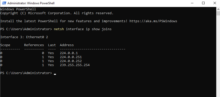
On Windows, we can use the following command to display the multicast groups currently joined by the operating system as already shown in Part 1. Besides well-known multicast groups that Windows joins automatically, the output also includes application-specific groups joined dynamically at runtime.
PS> netsh interface ip show joins
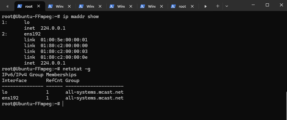
On Linux, the multicast groups currently joined by the operating system can be displayed by using the ip maddr show or netstat -g commands.
Unlike Windows, a default installation typically joins only the 224.0.0.1 (All Hosts) multicast group, while additional well-known groups such as mDNS, SSDP, or application-specific multicast groups are joined only when the corresponding services or applications are running.
On Linux,
mDNSis usually provided by Avahi. (apt install avahi-daemon)Linux also supports
SSDP, but there is no single built-in daemon equivalent to Windows’ SSDP Discovery service.
# ip maddr show
# netstat -g
Troubleshooting
IGMP Membership Reports Not Forwarded to the Upstream VLAN
Although the multicast receiver correctly joined the multicast group and pfSense received the corresponding IGMP Membership Reports, the reports never reached the upstream VLAN.
The following troubleshooting steps and packet captures were used to investigate why the IGMP Proxy failed to forward the membership information and, consequently, the multicast traffic.
To say it right away, the root cause was ultimately the unchecked Allow IP Options setting on the pfSense downstream interface (VLAN 20 NIC).
The Allow IP Options setting must be enabled on the VLAN 20 interface (downstream interface) firewall rule, as this is where the receiver’s IGMP Membership Reports, including the IPv4 Router Alert option, first enter the pfSense firewall.
Navigate to Firewall -> Rules -> VLAN 20 (downstream interface) and click on Edit.
Even a wide-open “Allow All” rule in pfSense will silently drop packets with IP options unless you explicitly tell that specific rule to permit them. Because an IGMP Join packet contains the “Router Alert” IP option, pfSense strips it at the firewall boundary, preventing it from ever reaching the IGMP proxy daemon to be forwarded to VLAN 10 (upstream interface).
Scroll down to the Extra Options section.
Click on Display Advanced.
Enable and check Allow IP options.
Allow packets with IP options to pass. Otherwise they are blocked by default. This is usually only seen with multicast traffic.
For the VLAN 10 rule (upstream interface), you do not need to enable it:
- The Receiver (VLAN 20): Sends an IGMP Join packet to the pfSense gateway. This packet contains the “Router Alert” IP option, so the VLAN 20 firewall rule must explicitly allow it to pass into the firewall engine.
- The pfSense IGMP Proxy Daemon: Once the firewall lets the packet pass, the internal IGMP proxy processes it. The proxy then generates its own fresh IGMP Join packet locally from the firewall itself and injects it directly out of the VLAN 10 interface.
- The Sender (VLAN 10): Because pfSense’s firewall rules only inspect incoming traffic on an interface, the locally-generated IGMP Join exiting the VLAN 10 interface is allowed out automatically. Furthermore, the actual multicast video stream coming back into VLAN 10 from our FFmpeg server consists of standard UDP packets, these do not contain IP options, so our standard “Allow All” rule on VLAN 10 will handle them perfectly.
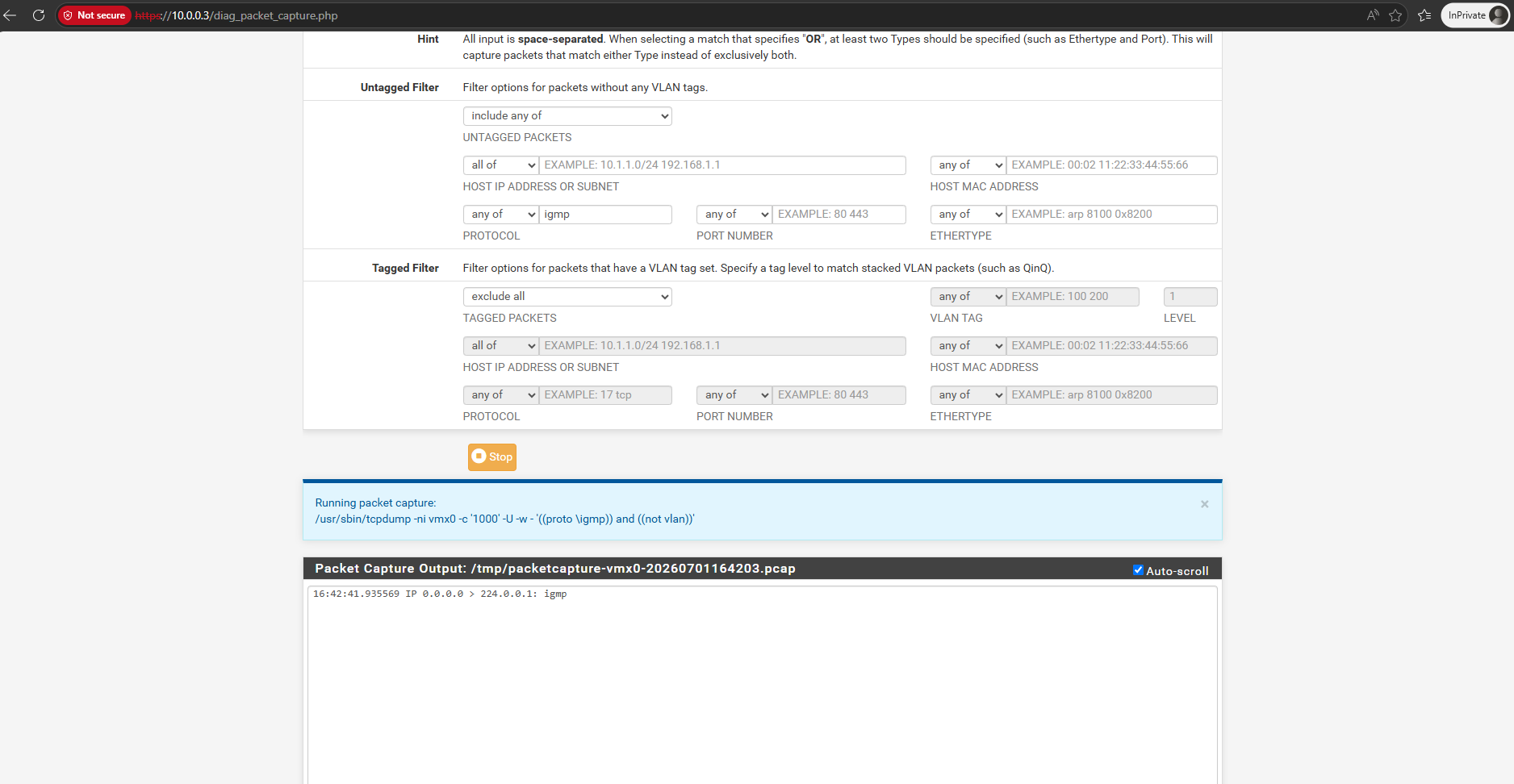
To see whats happen under the hood, I first captured traffic on the downstream interface (VLAN 20) to see if the IGMP Membership Report (Join) is successful forwarded to pfSense.
Below I was capturing IGMP traffic on pfSense on its VLAN 20 interface where the VLC receiver VM sends the IGMP Membership Report (Join) to see if they will correct forwarded to pfSense, looks good below.
Below we can see that Windows joined the group and pfSense receives the Membership Reports.
10.0.20.245 > 239.1.1.1: igmp
Next, we capture IGMP traffic on the VLAN 10 interface to see if the join is forwarded to the FFmpeg streaming source VMs VLAN. Despite the receiver VM successfully sending the request, the packet capture on VLAN 10 remains completely empty.
It is important to understand that the join request is not actually forwarded 1:1 from the client to the FFmpeg server. Instead, pfSense acts as a middleman: it must intercept the incoming membership report on VLAN 20, process it internally, and then pfSense itself sends out a brand new, locally-generated join request onto the VLAN 10 interface. Since our capture on the VLAN 10 interface shows absolutely nothing, it means this crucial interception and regeneration process is failing entirely.
The Join is not being forwarded upstream by igmpproxy.
On VLAN 10 we should see an IGMP membership report related to 239.1.1.1, not only:
0.0.0.0 > 224.0.0.1: igmp
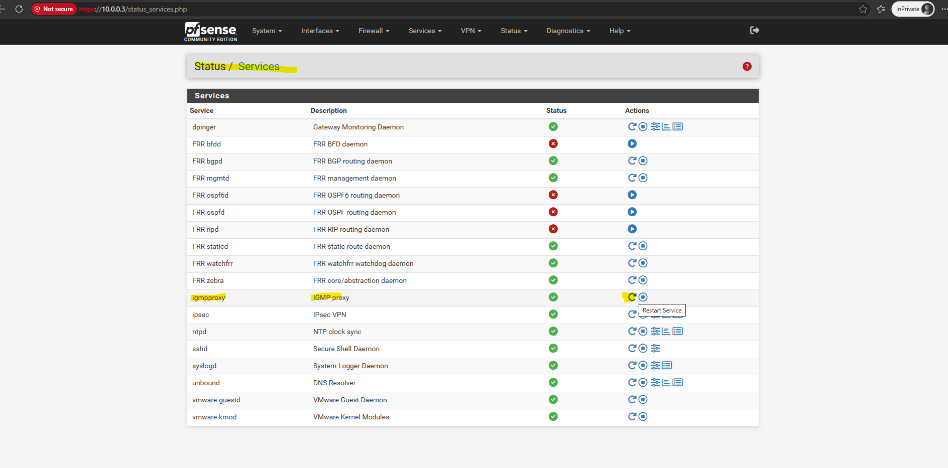
I also tried to restart the IGMP proxy service under Status → Services → igmpproxy → Restart.
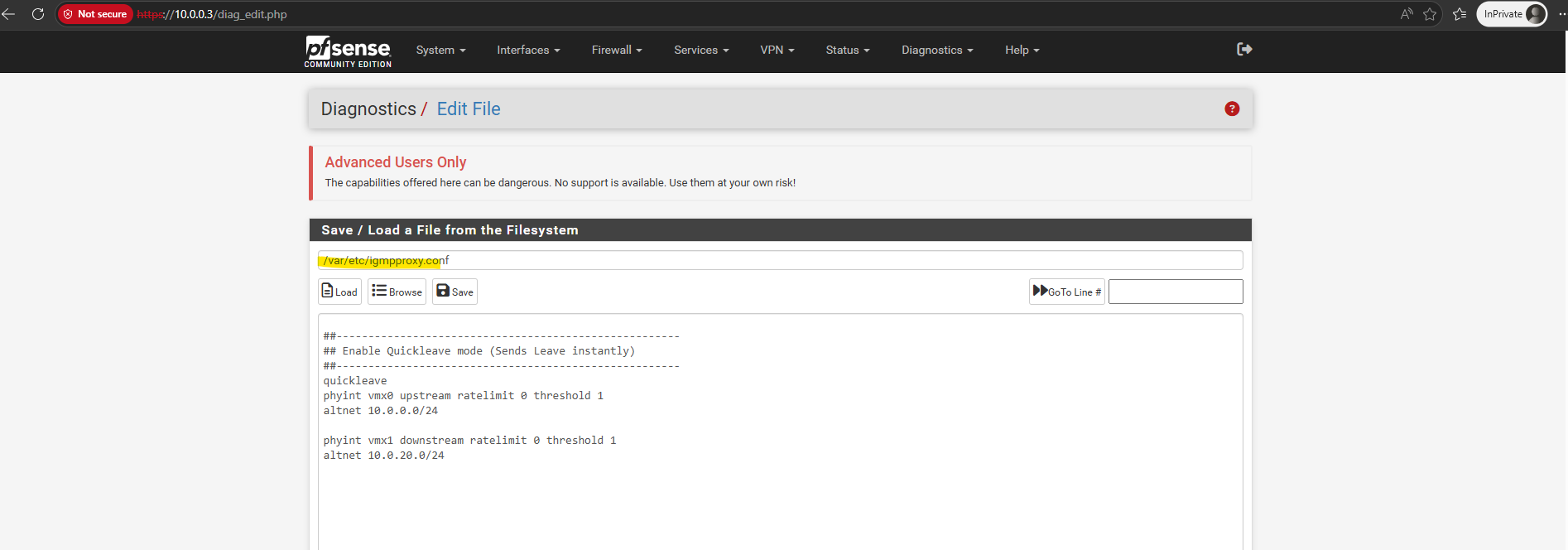
And checking the IGMP proxy config in /var/etc/igmpproxy.conf.
As already mentioned, finally the root cause was just a missing checked Allow IP options.
Links
IGMP Proxy
https://docs.netgate.com/pfsense/en/latest/services/igmp-proxy.htmlPackets with IP Options
https://docs.netgate.com/pfsense/en/latest/troubleshooting/log-filter-blocked.html#packets-with-ip-optionsIP Router Alert Considerations and Usage
https://www.rfc-editor.org/info/rfc6398/