How Multicast Traffic Works in VMware vSphere – Testing VSS (Basic Multicast Filtering) vs VDS (IGMP/MLD Snooping) with Video Streaming – Part 1
Multicast traffic is commonly used for IPTV, video surveillance systems, financial market data feeds, software deployment solutions, and other applications that need to efficiently distribute the same data stream to multiple receivers.
Unlike unicast traffic, where the sender must transmit a separate stream to each client, multicast allows a single stream to be replicated by the network only where required.
When multicast applications are deployed on VMware vSphere, administrators often encounter questions such as:
- Does VMware vSphere support multicast traffic?
- What is the difference between multicast handling on a vSphere Standard Switch (VSS) and a vSphere Distributed Switch (VDS)?
- What does IGMP Snooping actually do?
- Why does IGMP Snooping require an IGMP Querier?
- Why do multicast streams eventually stop after about four minutes?
- Does a VDS reduce multicast traffic on the physical network?
- When is a VDS beneficial, and when is a VSS perfectly sufficient?
To answer these questions, I built a small lab environment consisting of a multicast video streaming server and multiple client virtual machines. Using both vSphere Standard Switches and vSphere Distributed Switches, I analyzed how multicast traffic is forwarded inside the ESXi host, how IGMP Snooping affects traffic distribution, and how multicast behaves on the physical network.
In this post, we will walk through the multicast fundamentals, build a simple streaming lab, capture and analyze the traffic flow, and demonstrate the practical differences between VSS and VDS in VMware vSphere.
In this part, we focused on multicast communication within a single VLAN.
In Part 2, we’ll extend the lab beyond a single broadcast domain and configure multicast routing across multiple VLANs by using pfSense and IGMP.
- When Does the Difference Between VSS and VDS Matter?
- Understanding Unicast, Broadcast, and Multicast
- Under the Hood: How Basic Multicast Filtering Works on a vSphere Standard Switch (VSS)
- What is IGMP and Why Is It Needed?
- What Is IGMP Snooping?
- Under the Hood: Why IGMP Snooping Needs an IGMP Querier
- Multicast Traffic Flow Inside an ESXi Host
- Does a VDS Reduce Physical Network Traffic?
- Building a Multicast Video Streaming Lab
- Creating Multiple Video Sources for the Mosaic Stream
- Receiving the Video Streams on the Mosaic Server
- Building the Mosaic Stream
- Creating Multicast Receiver Clients
- Configuring Multicast Streaming with FFmpeg and VLC
- Verify and Analyse Multicast Traffic
- Testing with a vSphere Standard Switch (VSS)
- Migrating to a vSphere Distributed Switch (VDS)
- Comparing VSS vs. VDS
- Troubleshooting
- Links
When Does the Difference Between VSS and VDS Matter?
In a lab environment with only a single multicast stream, there is virtually no observable difference between a vSphere Standard Switch (VSS) using Basic multicast filtering and a vSphere Distributed Switch (VDS) with IGMP/MLD Snooping.
Since only one multicast group is active, no unintended multicast traffic is forwarded to receivers, and both switch types behave almost identically.
The differences become relevant only when multiple multicast streams are active simultaneously. In such environments, different multicast IP groups can map to the same Ethernet multicast MAC address.
A VSS using Basic multicast filtering cannot distinguish between these groups and may forward additional multicast streams to a virtual machine that subscribed to only one of them.
A VDS with IGMP/MLD Snooping, however, tracks the actual IP multicast group memberships and forwards only the requested streams.
How vSphere Standard Switch (VSS) using Basic multicast filtering works we will see further down in this post.
Understanding Unicast, Broadcast, and Multicast
IP networks support three primary communication models: unicast, broadcast, and multicast. Each determines how packets are delivered from a sender to one or more receivers and has different implications for network bandwidth and scalability.
Unicast
Unicast is the most common communication model and represents one-to-one communication. A sender transmits packets directly to a single destination IP address, and each receiver requires its own individual stream.
For example, if an FFmpeg server streams the same video to four VLC clients using unicast, it must send four separate streams, consuming four times the bandwidth on both the server and the network.
Broadcast
Broadcast represents one-to-all communication within a Layer 2 broadcast domain. Packets are delivered to every device in the same VLAN or subnet, regardless of whether they are interested in the traffic.
While broadcasts are useful for protocols such as ARP and DHCP, they are inefficient for applications like video streaming because every host must receive and process the traffic.
Multicast
Multicast provides one-to-many communication. Instead of creating a separate stream for every client, the sender transmits a single stream to a multicast group address (for example, 239.1.1.1). Only clients that explicitly join the multicast group using IGMP (Internet Group Management Protocol) receive the traffic.
This approach significantly reduces bandwidth consumption and is therefore widely used for IPTV, live video distribution, market data feeds, and other real-time streaming applications.
When IGMP Snooping is enabled on network switches, multicast traffic is forwarded only to switch ports where interested receivers are connected, preventing unnecessary flooding throughout the network.
In this lab, FFmpeg streams a single MPEG-TS video stream to the multicast group 239.1.1.1.
Multiple VLC clients subscribe to this group using IGMP, allowing all receivers to view the same stream while the FFmpeg server transmits only a single copy of the video.
This demonstrates one of the key advantages of multicast over unicast for one-to-many streaming scenarios.
Under the Hood: How Basic Multicast Filtering Works on a vSphere Standard Switch (VSS)
At first glance, VMware’s Basic multicast filtering appears somewhat surprising. Unlike a physical Ethernet switch, a vSphere Standard Switch (VSS) is able to avoid flooding multicast traffic to every virtual machine, even though it does not implement IGMP Snooping.
Understanding why requires looking at how physical switches learn MAC addresses and how a virtual switch differs fundamentally from a hardware switch.
A physical Ethernet switch builds its CAM (Content Addressable Memory) table exclusively by learning the source MAC address of frames arriving on its physical ports.
A Content Addressable Memory (CAM) table is a high-speed hardware memory used in Layer 2 network switches to map device MAC addresses to physical switch ports. Unlike standard RAM that retrieves data by its address, CAM searches by content: you provide the MAC address, and it instantly returns the port.
For more advanced operations like Layer 3 routing or Access Control Lists (ACLs), switches use TCAM (Ternary Content Addressable Memory). While CAM can only search for exact binary matches (
0sand1s), TCAM can use a third state wildcards (or “don’t care” bits) which allows it to search for multiple variables simultaneously, such as IP addresses, protocols, and QoS settings.
Since multicast destination MAC addresses, such as 01:00:5E:01:01:01 for the multicast group 239.1.1.1 never appear as source addresses, a physical switch cannot learn them dynamically.
Without IGMP Snooping, multicast frames are therefore treated as unknown multicast and flooded to every port within the VLAN, similar to broadcast traffic.
A physical Ethernet switch learns like this:
Frame arrives

Source MAC = 00:11:22:33:44:55

--> CAM Table:
00:11:22:33:44:55 -> Port 5
It never learns destination MACs.
Now a multicast frame (multicast group 239.1.1.1) arrives:
Destination MAC

01:00:5E:01:01:01
Has it ever seen this as a source? Of course No. Therefore unknown multicast which is flooded like broadcast to all physical ports on a physical switch.
A vSphere Standard Switch (VSS), however, operates differently. Because it is implemented inside the hypervisor, it already knows which virtual machine is connected to each virtual port. When a guest operating system registers a multicast MAC address with its virtual network adapter (e.g. when a VLC client starts playing a multicast stream as shown further down), the VSS can associate that multicast MAC with the corresponding virtual port.
This enables Basic multicast filtering without inspecting IGMP Membership Reports.
However, because Basic multicast filtering operates only at Layer 2 using multicast Ethernet MAC addresses, it cannot distinguish between different IP multicast groups that map to the same multicast MAC address.
When multiple IPv4 multicast streams (like
239.1.1.1and239.129.1.1) are transmitted, they map down to the exact same Layer 2 destination MAC address (01:00:5e:01:01:01) due to the way IP-to-MAC mathematical conversion drops 5 bits of the IP address.
This limitation is overcome by IGMP Snooping, which tracks Layer 3 IP multicast group memberships instead of relying solely on multicast MAC addresses.
IGMP Snooping can be enabled on both physical Ethernet switches and a vSphere Distributed Switch (VDS), allowing them to build IGMP Snooping tables and forward multicast traffic only to ports with receivers that have explicitly joined the corresponding multicast group.
What is IGMP and Why Is It Needed?
Unlike unicast or broadcast communication, multicast traffic is not automatically delivered to every device on the network. Instead, receivers must explicitly indicate their interest in receiving traffic for a specific multicast group. This is the purpose of the Internet Group Management Protocol (IGMP).
IGMP is used by IPv4 hosts (IPv6 hosts using MLD Multicast Listener Discovery ) and adjacent multicast routers (or Layer 2 switches performing IGMP Snooping) to manage multicast group membership. When a client application, such as VLC, starts playing a multicast stream, the operating system sends an IGMP Membership Report (Join) to announce that it wants to receive traffic for the requested multicast group. Conversely, when playback stops, the client eventually leaves the group, allowing the network to stop forwarding the multicast stream to that receiver.
Without IGMP Snooping, a switch has only limited information about multicast receivers. In simple environments with a single multicast stream, this often has no noticeable impact because there is only one multicast group to forward. However, in larger environments with multiple simultaneous multicast streams, multicast filtering based solely on Ethernet multicast MAC addresses can result in additional multicast traffic being forwarded to receivers that subscribed to only one of the streams.
To avoid this, managed switches commonly implement IGMP Snooping. Rather than participating in IGMP themselves, they simply inspect (“snoop”) IGMP Membership Reports exchanged between hosts and multicast routers. Using this information, the switch builds a table of multicast group memberships and forwards multicast traffic only to ports where interested receivers are connected.
The following diagram illustrates the multicast join process:
- A client starts playback of a multicast stream in VLC.
- The operating system sends an IGMP Membership Report (Join) for the multicast group (for example,
239.1.1.1) to the well-known multicast address224.0.0.22. - The switch observes the IGMP message and records that the corresponding switch port is interested in the multicast group.
- The multicast source continues sending a single stream to
239.1.1.1. - The switch forwards the stream only to ports where clients have joined the multicast group, preventing unnecessary multicast flooding.
- When the client stops playback and leaves the group, the switch eventually removes the port from its forwarding table and stops forwarding the multicast traffic to that port.
In this lab, the Windows VLC clients join the multicast group 239.1.1.1 by sending an IGMPv3 Membership Report to 224.0.0.22. This behavior can easily be observed with Wireshark shown further down, making it an excellent way to understand how multicast group membership is established in practice.
The multicast address
224.0.0.22is a well-known IPv4 link-local multicast address reserved for IGMPv3. Hosts send IGMP Membership Reports to this address to announce the multicast groups they want to join, allowing multicast routers and switches performing IGMP Snooping to learn which ports should receive the multicast traffic.
What Is IGMP Snooping?
By itself, multicast traffic is transmitted to a multicast group address rather than to a specific destination host. Without additional intelligence in the network, Ethernet switches treat multicast traffic similarly to broadcast traffic and flood it to all ports within the same VLAN. While this guarantees delivery to interested receivers, it also wastes bandwidth and unnecessarily loads devices that never requested the stream.
IGMP Snooping is a Layer 2 switch feature that prevents this unnecessary flooding. Instead of participating in the IGMP protocol itself, the switch passively monitors (“snoops”) IGMP Membership Reports and Leave messages sent by multicast receivers. Using this information, it builds a multicast forwarding table that maps multicast groups to the switch ports where subscribed clients are connected.
Once this table has been populated, multicast traffic is forwarded only to the ports associated with members of the corresponding multicast group. Ports without subscribed receivers no longer receive the multicast stream, significantly reducing unnecessary traffic on the network.
In this lab, enabling IGMP Snooping on the physical NETGEAR switches demonstrated this behavior. With IGMP Snooping disabled, Wireshark captured the multicast MPEG-TS stream on VMs that had never joined the multicast group. After enabling IGMP Snooping, only VMs that explicitly joined 239.1.1.1 using IGMP continued to receive the multicast traffic, while non-subscribed VMs no longer saw the stream.
Below we’ll see that the same principle applies to a vSphere Distributed Switch (VDS) when IGMP/MLD Snooping is enabled, although the implementation differs from a physical switch.
Under the Hood: Why IGMP Snooping Needs an IGMP Querier
IGMP Snooping alone is not sufficient to maintain multicast forwarding. It relies on an IGMP Querier, which periodically sends IGMP General Queries to the All Hosts multicast address (224.0.0.1).
The
224.0.0.1multicast address represents the All Hosts group and is joined automatically by multicast-capable hosts like Windows and Linux. Unlike application-specific multicast groups such as239.1.1.1, no explicit IGMP Membership Report is required to receive packets sent to this group.Unlike the limited broadcast address
255.255.255.255, which reaches every host on the local subnet using broadcast,224.0.0.1is a dedicated multicast group for all multicast-capable hosts.
Receivers that are still interested in a multicast stream respond with IGMP Membership Reports, allowing the switch to refresh its multicast forwarding table.
Without an IGMP Querier, receivers send only their initial IGMP Membership Report (Join) when joining a multicast group. As a result, multicast membership entries eventually age out, causing multicast forwarding to stop even though the application is still running.
When IGMP/MLD Snooping is enabled on a vSphere Distributed Switch (VDS), VMware automatically provides an IGMP Querier for the VLAN by sending periodic IGMP General Queries (0.0.0.0 → 224.0.0.1).
As shown in the following Wireshark capture, these queries originate from the source address
0.0.0.0because the VDS itself is a Layer 2 virtual switch rather than a Layer 3 multicast router, such as pfSense configured with IGMP Proxy (covered in Part 2), and therefore does not own an IP address.The Max Resp Time field is set to 1.0 second, indicating the maximum time receivers have to respond with an IGMP Membership Report to confirm that they are still interested in receiving multicast traffic. This allows the VDS to keep its multicast forwarding table up to date.
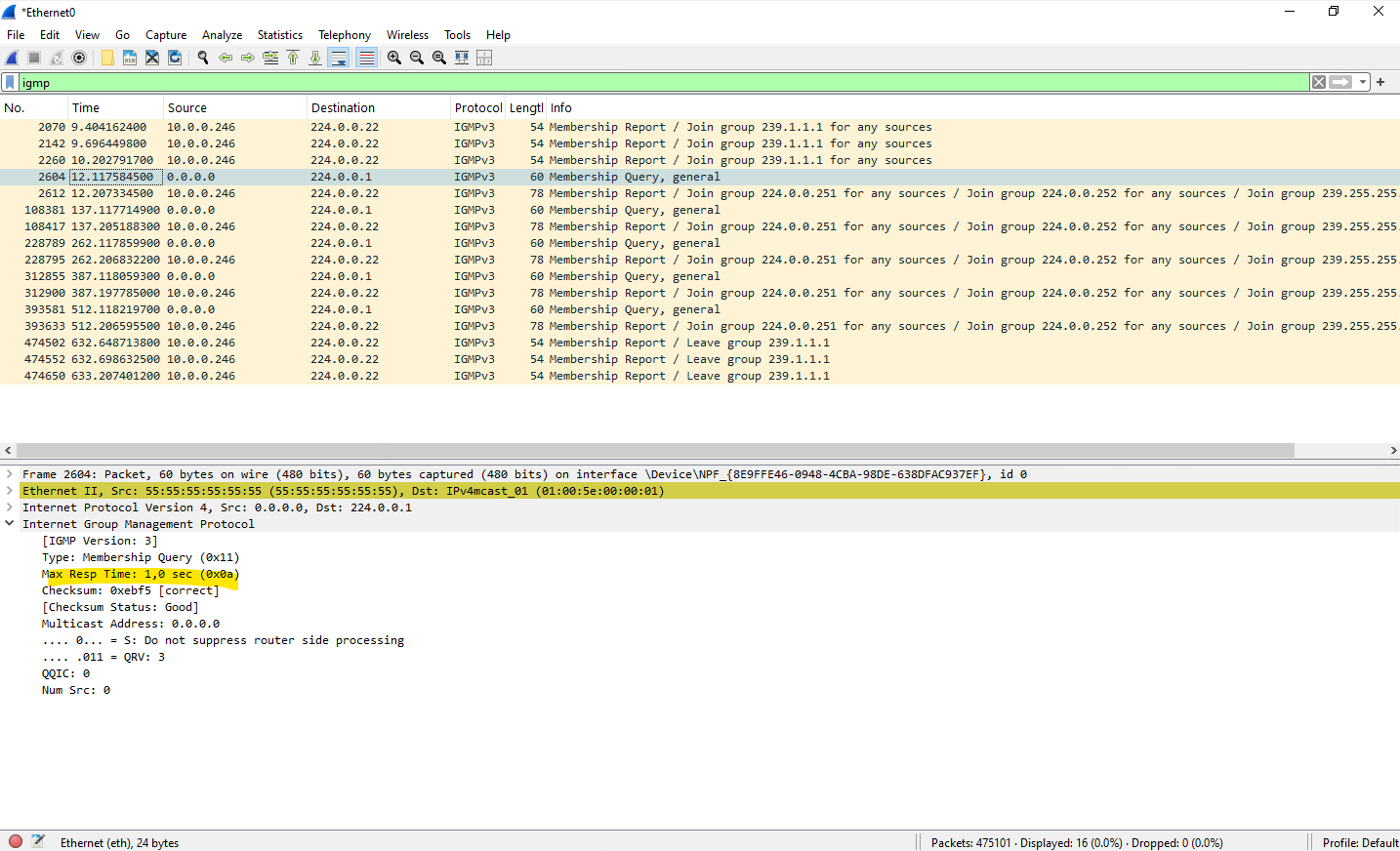
This ensures multicast memberships remain active and multicast forwarding continues as long as receivers are still subscribed.
For the scenarios covered in this Part 1, there is generally nothing to worry about. Whether you use a vSphere Standard Switch (VSS) which is using Basic Filtering Mode shown further down or a vSphere Distributed Switch (VDS) with IGMP/MLD Snooping enabled (by default but can also switched to Basic Filtering Mode), multicast traffic continues to flow as expected while the sender and receivers remain within the same VLAN.
The only exception encountered during testing was a physical switch performing IGMP Snooping without also providing the IGMP Querier role.
In that case, multicast group memberships eventually expire because no periodic IGMP General Queries are sent to refresh them, causing multicast forwarding to stop after approximately four minutes.
For environments using a VSS or a VDS with Basic Multicast Filtering, enabling IGMP Snooping on physical switches without also providing an IGMP Querier is generally not recommended.
Either deploy an IGMP Querier to maintain multicast group memberships or disable IGMP Snooping on the physical switches to ensure multicast traffic continues to be forwarded.
Multicast Traffic Flow Inside an ESXi Host
When both the multicast source and one or more receivers reside on the same ESXi host, the multicast traffic does not necessarily leave the host. Instead, the ESXi virtual switch performs the forwarding locally between virtual ports, avoiding unnecessary transmission over the physical network.
This behavior is identical for both the vSphere Standard Switch (VSS) and the vSphere Distributed Switch (VDS). However, unlike the VSS, the VDS supports IGMP/MLD Snooping, allowing multicast traffic to be forwarded only to virtual machines that have joined the corresponding multicast group.
If IGMP/MLD Snooping is enabled on the VDS, the switch maintains multicast forwarding information for locally connected virtual machines in the same way that a physical switch does for physical ports. As a result, multicast traffic is delivered only to virtual ports associated with receivers that have joined the corresponding multicast group.
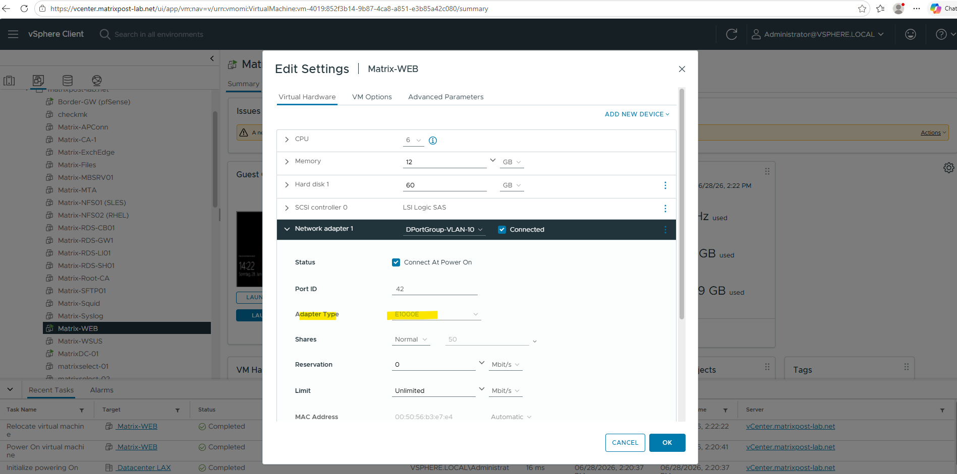
In my lab, this behavior was verified by placing the FFmpeg streaming VM and multiple Windows VMs on the same distributed port group and ESXi host. After replacing the legacy E1000E virtual network adapter with VMXNET3, only VMs that had joined the multicast group 239.1.1.1 continued to receive the multicast stream. At the same time, a Windows VM running on another ESXi host did not receive the multicast traffic, confirming that the physical NETGEAR switches also correctly enforced IGMP Snooping across the network.
To ensure that multicast traffic is handled efficiently and filtered at the hypervisor layer, I replaced the legacy E1000E virtual network adapter with VMXNET3 on the test VMs. The architectural reason for this change, and why the emulated E1000E driver forces the virtual switch to bypass group filtering and flood all multicast traffic directly into the guest OS, is analyzed in detail in the troubleshooting section later in this post.
This demonstrates that multicast forwarding decisions can occur at multiple layers. The VDS optimizes multicast delivery between local virtual machines on the same ESXi host, while physical switches independently apply IGMP Snooping to control multicast traffic forwarded between hosts.
Does a VDS Reduce Physical Network Traffic?
A key advantage of the vSphere Distributed Switch (VDS) with IGMP Snooping is its ability to precisely optimize multicast traffic boundaries. If a multicast source and its subscribed receivers reside on the same ESXi host, both the VDS and VSS are smart enough to route that traffic locally. However, because the vSphere Standard Switch (VSS) operates strictly in Basic Mode (Layer 2 MAC filtering), it is blind to Layer 3 IP multicast groups.
If multiple local streams share overlapping Multicast MAC addresses, or if a VM uses an unoptimized adapter like the E1000E, the VSS is forced to flood that duplicate traffic to local virtual ports and out to the physical uplinks.
By contrast, the VDS intercepts IGMP membership reports directly, ensuring that only the exact, requested IP multicast streams are processed. (Note: To achieve this optimization on either switch type, VMs must use the paravirtualized VMXNET3 adapter; using a legacy E1000E adapter forces an “All-Multicast” state (shown in the troubleshooting section) that bypasses VDS IGMP snooping logic entirely and causes flooding anyway). By combining VDS with VMXNET3, you completely prevent overlapping “ghost” traffic from ever consuming bandwidth on your physical uplinks or wasting CPU cycles on neighboring physical switches.
Building a Multicast Video Streaming Lab
The goal of this lab is to simulate a real-world multicast video distribution scenario. An Ubuntu VM running FFmpeg receives multiple video sources, combines them into a mosaic stream, and distributes the resulting video using IP multicast to multiple VLC clients.
Lab Architecture
The lab consists of a multicast sender VM, multiple multicast receiver VMs, and the underlying vSphere networking infrastructure used to transport the video stream. This setup allows us to analyze how multicast traffic behaves when using vSphere Standard Switches (VSS) and vSphere Distributed Switches (VDS).
                +------------------+
                | FFmpeg Mosaic VM |
                |                  |
Video 1 ------->|                  |
Video 2 ------->|    2x2 Mosaic    |----> Multicast 239.1.1.1:5004
Video 3 ------->|                  |
Video 4 ------->|                  |
                +------------------+
                          |
                          |
                    Multicast Group
                    239.1.1.1:6000
                          |
        -------------------------------------
        |                 |                 |
        v                 v                 v
   VLC Client 1     VLC Client 2     VLC Client 3
In the Testing with a vSphere Standard Switch (VSS) section further down, the lab setup is slightly modified. Instead of a single multicast stream, the FFmpeg server simultaneously transmits two multicast streams (239.1.1.1:6000 and 224.1.1.1:6000) to demonstrate multicast MAC aliasing and highlight the differences between VSS Basic multicast filtering and VDS IGMP/MLD Snooping.
                +------------------------+
                | FFmpeg Mosaic VM       |
                | sending a test pattern |
                +------------------------+
                          |
                          |
                    Multicast Group
                    239.1.1.1:6000
                    224.1.1.1:6000
                          |
        -------------------------------------
        |                 |                 |
        v                 v                 v
   VLC Client 1     VLC Client 2     VLC Client 3
Deploying the Multicast Server
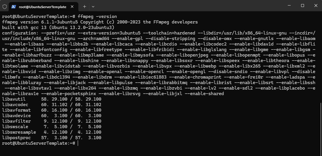
FFmpeg is a free and open-source multimedia framework capable of processing, converting, streaming, and recording audio and video content. In this lab, it is used to combine multiple video sources into a single mosaic stream and distribute the resulting video via IP multicast to multiple clients.
# apt update
# apt install ffmpeg

verify installation:
# ffmpeg -version
Creating Multiple Video Sources for the Mosaic Stream
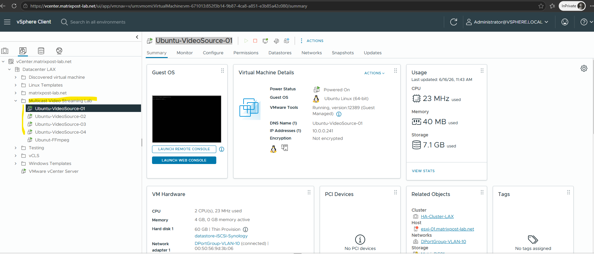
To simulate a real-world Mosaic Caster deployment, I created four independent video source virtual machines. Each VM generates its own video stream, which is later received by the FFmpeg server and combined into a single mosaic stream before being distributed to multiple clients via IP multicast.
- Ubuntu-VideoSource-01 (10.0.0.241)
- Ubuntu-VideoSource-02 (10.0.0.242)
- Ubuntu-VideoSource-03 (10.0.0.243)
- Ubuntu-VideoSource-04 (10.0.0.244)
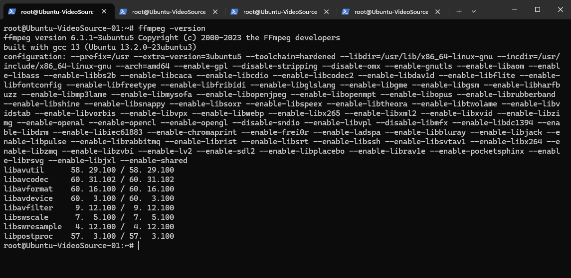
Since the video sources only need to generate and transmit video, the software requirements are minimal. For this lab, I installed FFmpeg on each source VM, which will be used to create and stream the video content over the network.
$ sudo apt update
$ sudo apt install -y ffmpeg

Verify:
$ ffmpeg -version
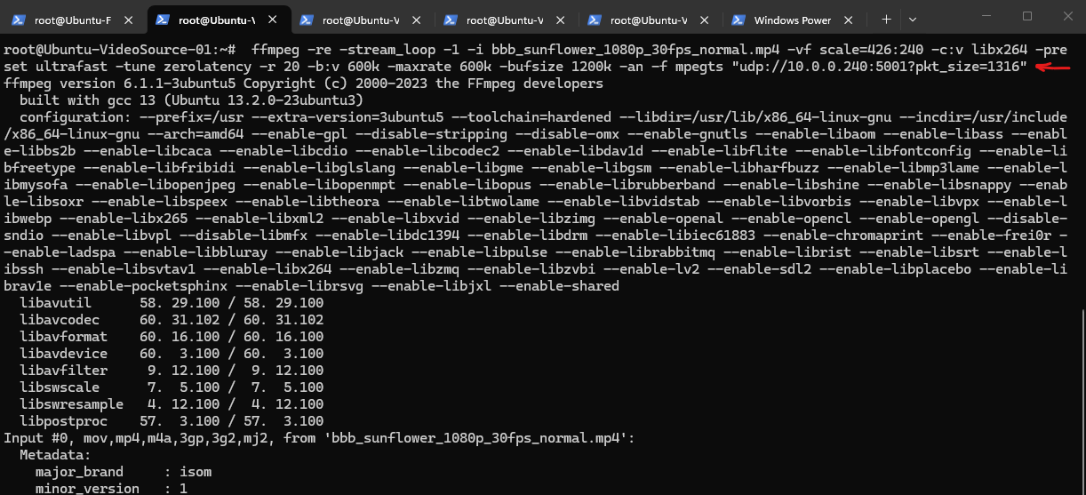
To later simulate multiple live video sources, each source VM continuously streaming a different locally stored video over UDP using FFmpeg. For this lab, I used freely available sample videos that are well suited for testing and demonstration purposes. They provide a convenient way to build realistic streaming scenarios without using copyrighted commercial video content. Links to all videos used in this article can be found in the Links section below.
Each stream is scaled to 426×240, encoded with H.264 at 20 FPS and 600 kb/s, and transmitted to the FFmpeg streaming server on a dedicated UDP port, where the individual streams are combined into a single multicast mosaic.
10.0.0.240 will be our Ubuntu-FFmpeg Mosaic Server.
# VideoSource-01
$ ffmpeg -re -stream_loop -1 -i bbb_sunflower_1080p_30fps_normal.mp4 -vf scale=426:240 -c:v libx264 -preset ultrafast -tune zerolatency -r 20 -b:v 600k -maxrate 600k -bufsize 1200k -an -f mpegts "udp://10.0.0.240:5001?pkt_size=1316"

# VideoSource-02
$ ffmpeg -re -stream_loop -1 -i sintel_trailer-1080p.mp4 -vf scale=426:240 -c:v libx264 -preset ultrafast -tune zerolatency -r 20 -b:v 600k -maxrate 600k -bufsize 1200k -an -f mpegts "udp://10.0.0.240:5002?pkt_size=1316"

# VideoSource-03
$ ffmpeg -re -stream_loop -1 -i spring.mp4 -vf scale=426:240 -c:v libx264 -preset ultrafast -tune zerolatency -r 20 -b:v 600k -maxrate 600k -bufsize 1200k -an -f mpegts "udp://10.0.0.240:5003?pkt_size=1316"

# VideoSource-04
$ ffmpeg -re -stream_loop -1 -i sample-5s.mp4 -vf scale=426:240 -c:v libx264 -preset ultrafast -tune zerolatency -r 20 -b:v 600k -maxrate 600k -bufsize 1200k -an -f mpegts "udp://10.0.0.240:5004?pkt_size=1316"
Receiving the Video Streams on the Mosaic Server
Before configuring multicast distribution, the FFmpeg Mosaic Server must first receive and process the individual video feeds.
In this step, the server subscribes to the four incoming UDP streams generated by the video source VMs and verifies that each stream is available for further processing.
With the video source VMs prepared, I can now start generating the individual video streams. I will run the already above shown commands on all four source virtual machines. Below shown for VideoSource-01.
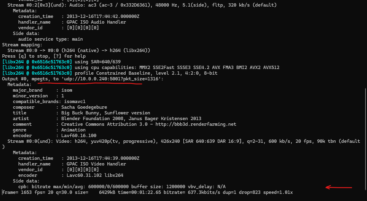
The following FFmpeg command streams a local stored video via UDP to the FFmpeg Mosaic Server, where it will later be combined with the other video sources into a single mosaic stream.
$ ffmpeg -re -stream_loop -1 -i bbb_sunflower_1080p_30fps_normal.mp4 -vf scale=426:240 -c:v libx264 -preset ultrafast -tune zerolatency -r 20 -b:v 600k -maxrate 600k -bufsize 1200k -an -f mpegts "udp://10.0.0.240:5001?pkt_size=1316"
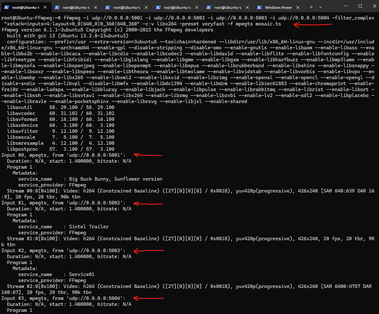
On our FFmpeg Multicast Server we now verify the incoming streams.
We can test each stream individually by running:
The errors at the beginning are normal when attaching to an already-running H.264 UDP stream.
FFprobe joined the stream in the middle and initially missed the SPS/PPS headers required to decode H.264. After a few moments it received a keyframe and the stream became readable.
For a headless server, use ffprobe to verify the incoming stream:
# ffprobe udp://0.0.0.0:5001
# ffprobe udp://0.0.0.0:5002
# ffprobe udp://0.0.0.0:5003
# ffprobe udp://0.0.0.0:5004

For a server having 3D/GUI rendering available use:
# ffplay udp://0.0.0.0:5001
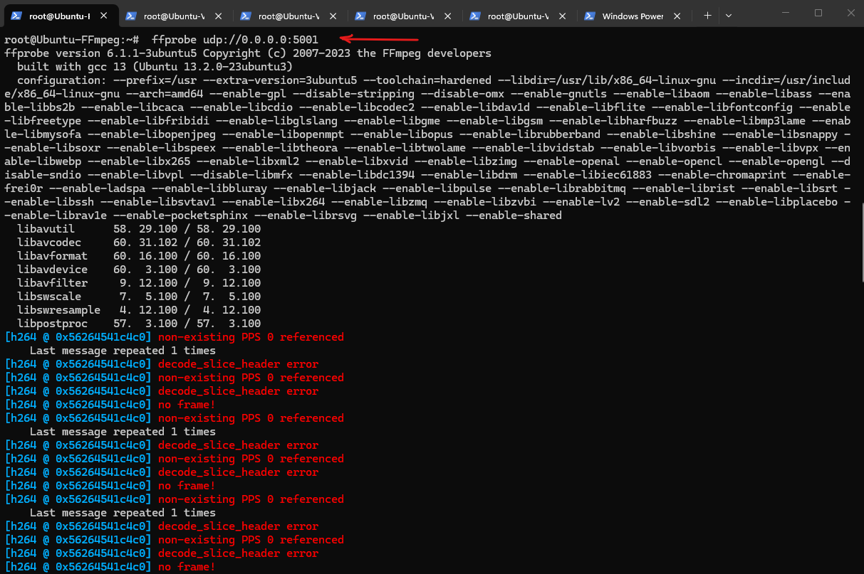
The important part is at the bottom and marked below.
This proves that the stream is arriving successfully.
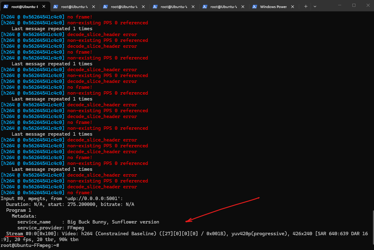
At this point, all four video source VMs are successfully streaming H.264 video to the FFmpeg server.
With the individual feeds validated and reachable, the next step is to combine them into a single 2×2 mosaic stream.
Building the Mosaic Stream
With all four video sources successfully streaming to the FFmpeg server, we can now combine them into a single mosaic stream.
Using FFmpeg’s powerful xstack filter, the individual video feeds can be arranged in a 2×2 layout, creating a video wall similar to what a commercial Mosaic Caster solution would generate.
To ensure that FFmpeg receives the complete H.264 stream initialization data (SPS/PPS headers), I first stopped all four source streams before starting the mosaic process on the FFmpeg server.
After the mosaic process was running and listening on the UDP ports, I restarted the four source streams, allowing FFmpeg to successfully detect and decode all incoming video feeds before combining them into the final mosaic stream.
On the FFmpeg server run:
ffmpeg \
-i udp://0.0.0.0:5001 \
-i udp://0.0.0.0:5002 \
-i udp://0.0.0.0:5003 \
-i udp://0.0.0.0:5004 \
-filter_complex "xstack=inputs=4:layout=0_0|640_0|0_360|640_360" \
-c:v libx264 \
-preset veryfast \
-f mpegts mosaic.ts
After the mosaic stream has been created on the FFmpeg server, the next step is to distribute this single stream via IP multicast and receive it on multiple client systems.
Each client will join the same multicast group and receive the identical mosaic video stream without requiring a separate unicast stream from the server.
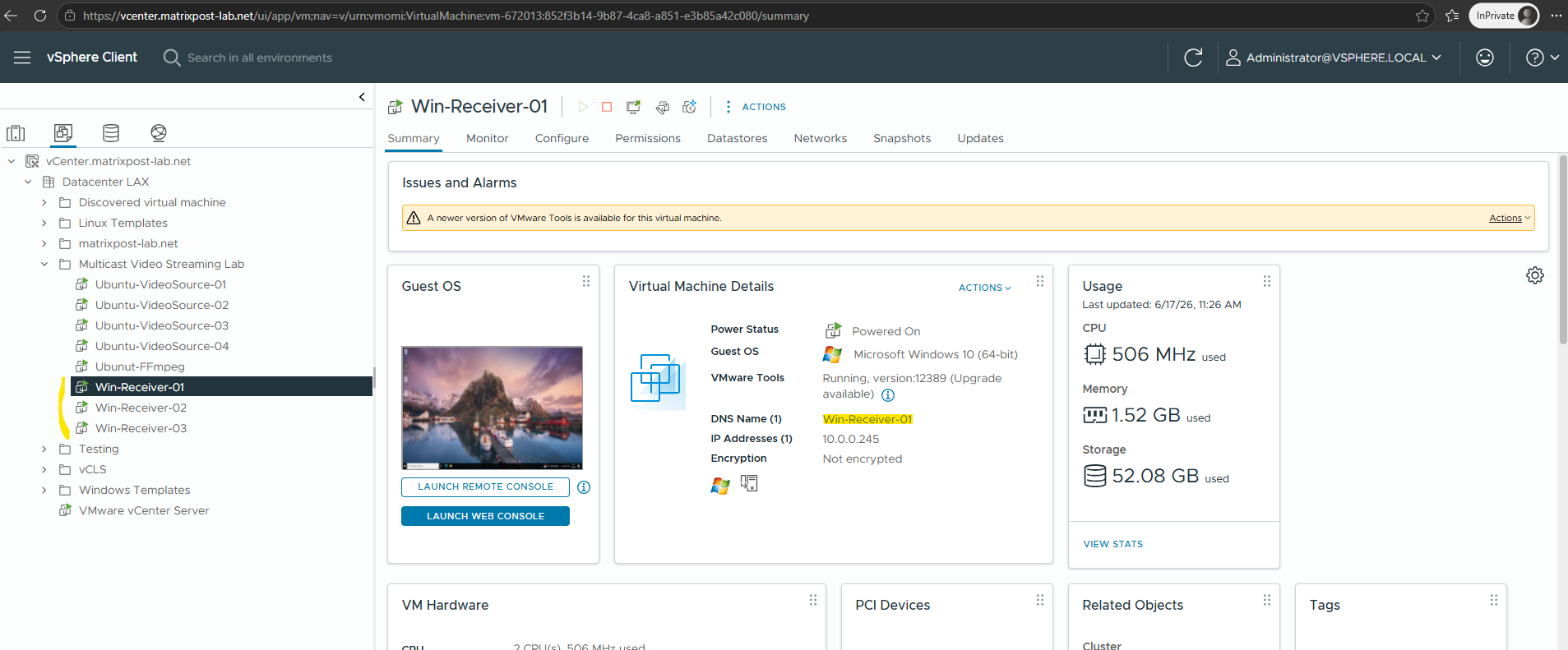
Creating Multicast Receiver Clients
To demonstrate the benefits of multicast distribution, I deployed three client virtual machines (Windows 10 using VLC) that will act as video receivers.
These clients will join the multicast group and receive the mosaic stream generated by the FFmpeg server, allowing us to observe how a single stream can efficiently be delivered to multiple viewers simultaneously.
Installing VLC on the Receiver Clients
These Windows systems will join the multicast group and act as viewers for the mosaic stream generated by the FFmpeg server, allowing us to verify multicast distribution to multiple clients simultaneously.
To display the multicast video stream, I installed VLC Media Player on each receiver VM.
VLC provides native support for UDP multicast streams and makes it easy to verify that multiple clients can simultaneously receive and display the same video feed.
We can download the VLC Media Player here.
With the receiver clients prepared, the next step is to configure the FFmpeg server to distribute the mosaic stream using IP multicast.
Instead of creating a separate video stream for each client, a single multicast stream will be transmitted and can be received simultaneously by any client that joins the multicast group.
Configuring Multicast Streaming with FFmpeg and VLC
With the video sources, mosaic server, and receiver clients in place, the lab environment is now ready for multicast testing.
The following steps configure the FFmpeg server to publish the mosaic stream via IP multicast and demonstrate how multiple clients can efficiently receive the same video stream from a single source.
Up to this point, the mosaic stream was written to a local file on the FFmpeg server for testing and validation purposes. While useful for verifying the video processing pipeline, this approach does not allow multiple clients to view the stream simultaneously.
-f mpegts mosaic.ts
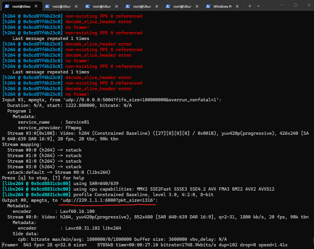
Rather than writing the mosaic to a local file, the following command turns the FFmpeg server into a multicast source.
The generated mosaic stream is transmitted to the multicast group 239.1.1.1:6000, allowing multiple receivers to view the same video feed without creating additional streams on the server.
The errors at the beginning are normal when attaching to an already-running H.264 UDP stream.
FFmpeg joined the stream in the middle and initially missed the SPS/PPS headers required to decode H.264. After a few moments it received a keyframe and the stream became readable.
ffmpeg -thread_queue_size 4096 -i "udp://0.0.0.0:5001?fifo_size=100000000&overrun_nonfatal=1" -thread_queue_size 4096 -i "udp://0.0.0.0:5002?fifo_size=100000000&overrun_nonfatal=1" -thread_queue_size 4096 -i "udp://0.0.0.0:5003?fifo_size=100000000&overrun_nonfatal=1" -thread_queue_size 4096 -i "udp://0.0.0.0:5004?fifo_size=100000000&overrun_nonfatal=1" -filter_complex "[0:v][1:v][2:v][3:v]xstack=inputs=4:layout=0_0|426_0|0_240|426_240[out]" -map "[out]" -c:v libx264 -preset ultrafast -tune zerolatency -r 20 -b:v 1800k -maxrate 1800k -bufsize 3600k -an -f mpegts "udp://239.1.1.1:6000?pkt_size=1316"
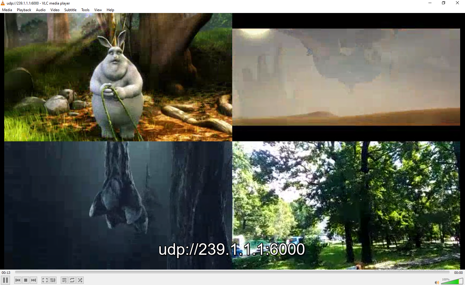
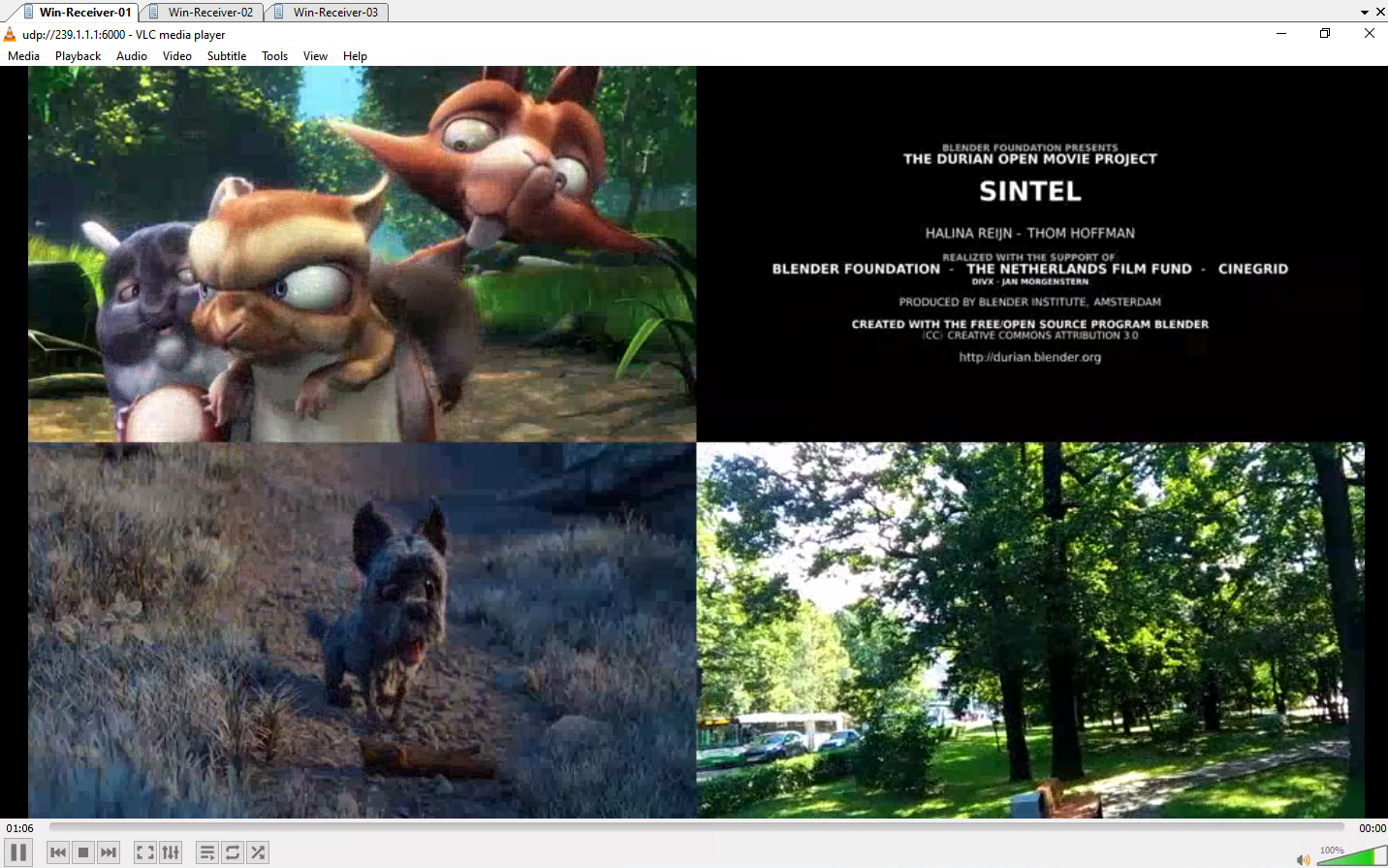
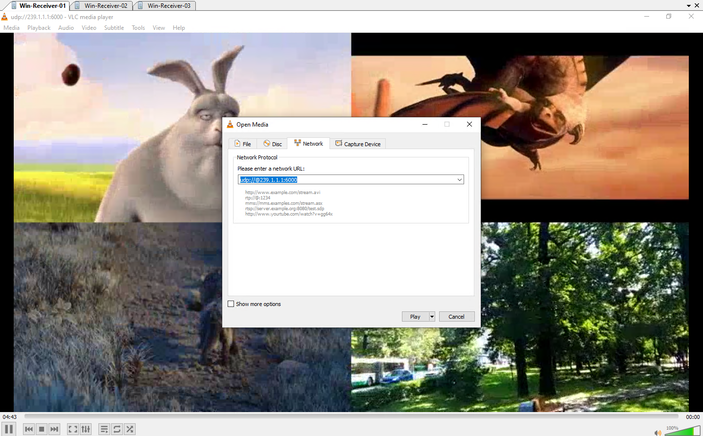
To receive the multicast stream on our receiver clients (Windows 10 VMs), open VLC Media Player and select Media > Open Network Stream. Then enter the multicast address in the format udp://@239.1.1.1:6000 and click Play to join the multicast group and start receiving the stream.
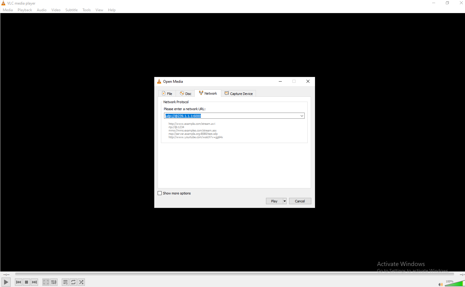
Once playback starts, VLC displays the combined multicast stream as a 2×2 video mosaic containing all four source streams. At the beginning of the playback, you can also see the configured multicast UDP URL (udp://@239.1.1.1:6000) before it automatically disappears.
Verify and Analyse Multicast Traffic
The following checks help confirm that the video sources, FFmpeg mosaic server, and VLC clients are communicating as expected before analyzing the network behavior.
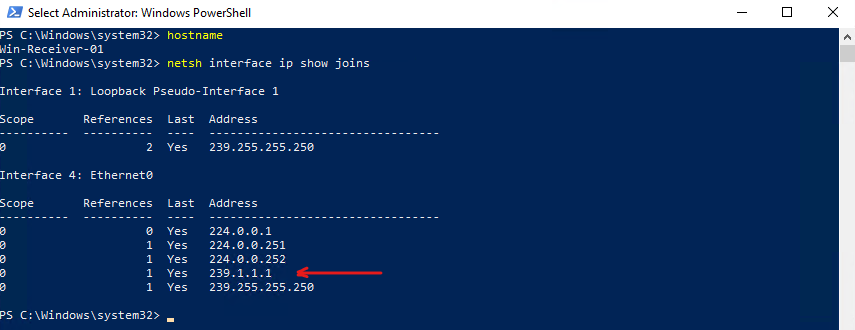
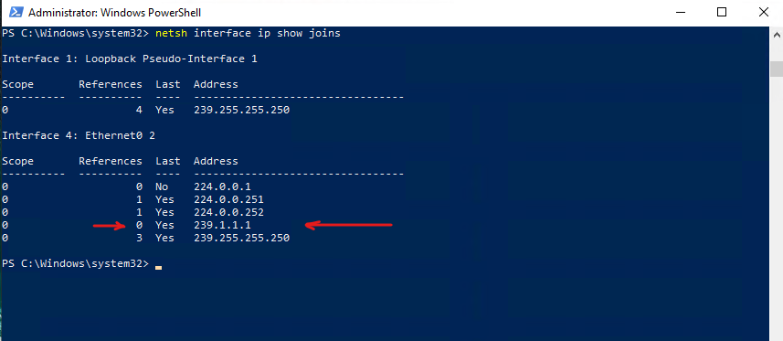
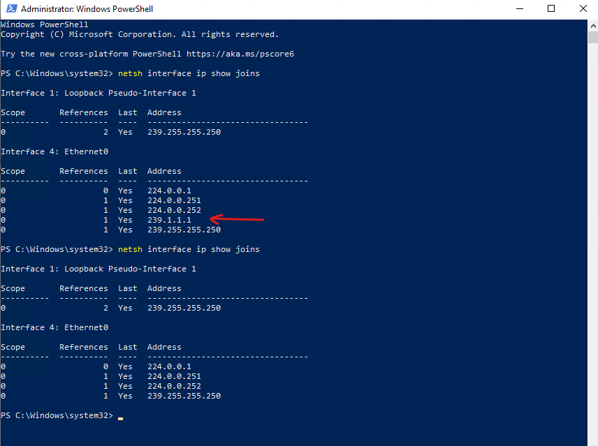
When a VLC client starts playing a multicast stream, Windows automatically joins the corresponding multicast group by sending an IGMP Membership Report. This can be verified using the following command.
After opening the multicast stream in VLC, the output confirms that the client has successfully joined the multicast group
239.1.1.1by sending an IGMP Membership Report, allowing it to receive the multicast traffic.A reference count of 1 indicates that a single application or socket is currently subscribed to the multicast group.
The Internet Group Management Protocol (IGMP) is a network-layer protocol used to manage IP multicast communication. It allows multiple devices on an IPv4 network to “subscribe” to a single data stream (like live video or IPTV) simultaneously, optimizing bandwidth by only sending data to devices that explicitly request it
PS> netsh interface ip show joins
After closing VLC, the multicast group initially remains visible with a reference count of 0. This indicates that no application is actively subscribed to the group anymore, while Windows temporarily retains the membership entry until the IGMP leave procedure and related timers have completed.
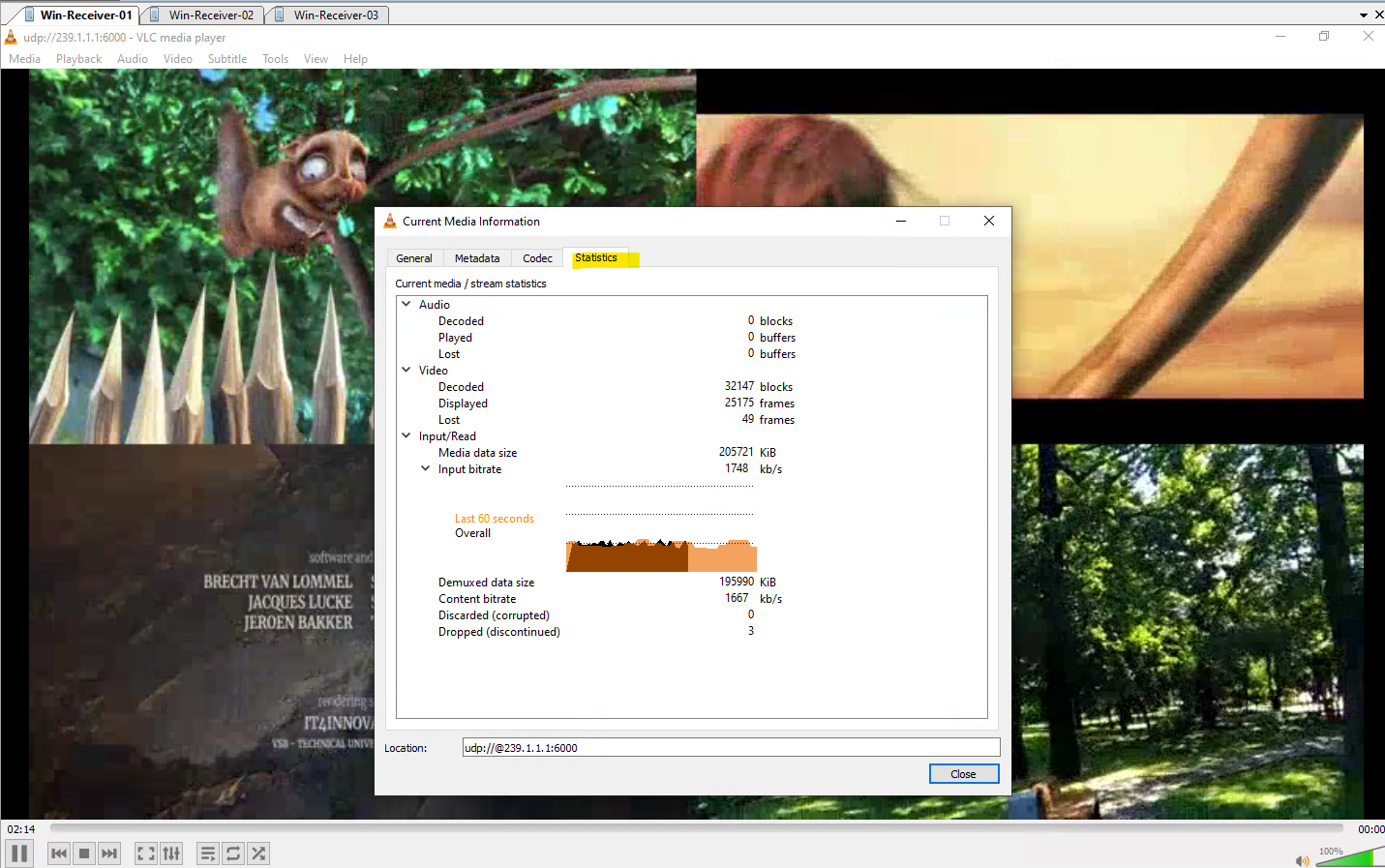
Under Tools -> Codec Information or Media Information -> Statistics we will see the received bitrate, lost packets and displayed frames.
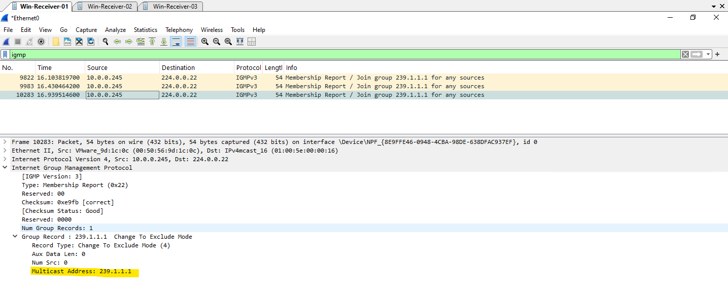
After starting playback of the multicast stream in VLC on Win-Receiver-01, I use Wireshark to capture the network traffic and intercept the IGMP join request sent by the client.
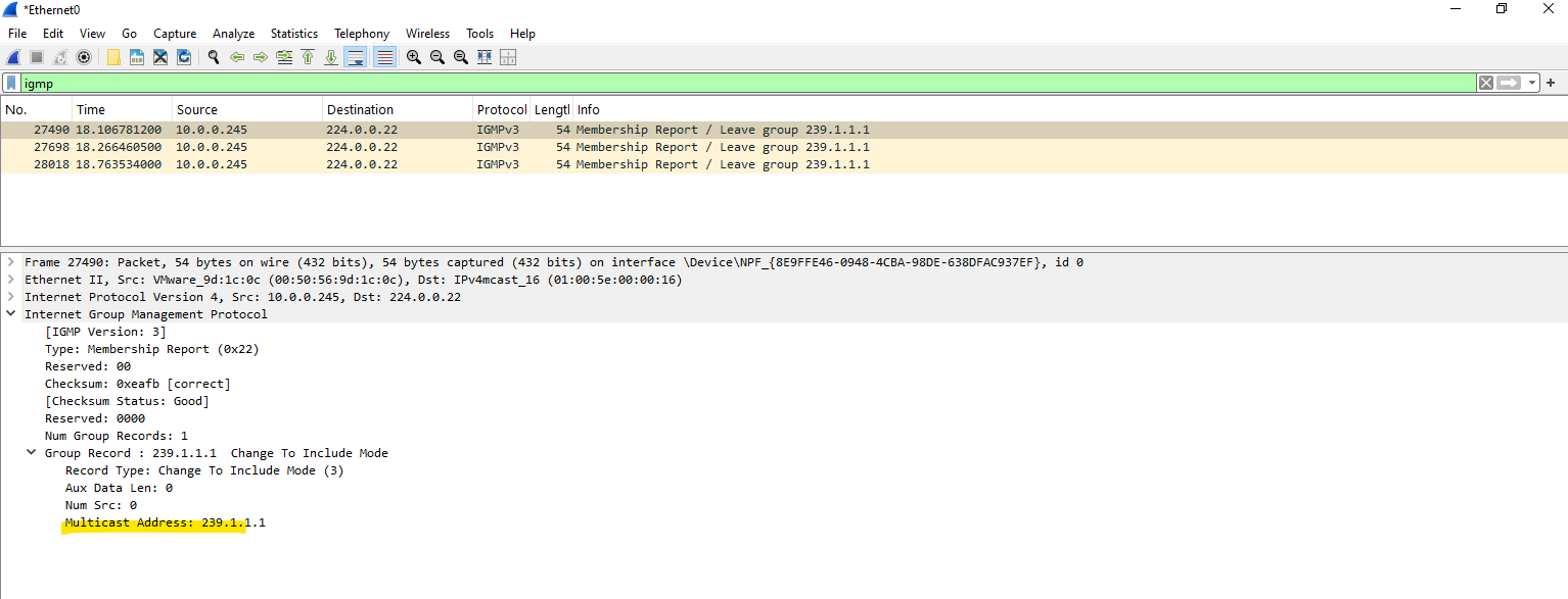
Wireshark immediately captures multiple IGMPv3 Membership Reports sent from the Windows 10 client (Win-Receiver-01 10.0.0.245) to the multicast address 224.0.0.22.
The destination address 224.0.0.22 is a well-known multicast address reserved for IGMPv3 Membership Reports. It is used only to send multicast join and leave messages to multicast routers or IGMP-snooping switches, the client itself does not join the 224.0.0.22 multicast group.
Each report contains a Join Group request for 239.1.1.1 (Any-Source Multicast), confirming that the Windows client has successfully joined the multicast group. It is normal to see the same membership report multiple times, as IGMP sends repeated reports to increase the reliability of the multicast join process.
Stopping the multicast playback in VLC immediately triggers three IGMPv3 Membership Report messages containing Leave Group 239.1.1.1. These messages notify the network that the client is no longer interested in receiving traffic for the multicast group, allowing IGMP Snooping switches to update their forwarding tables accordingly.
Running
netsh interface ip show joinsafter stopping the playback confirms that the client has successfully left the multicast group. As expected, the membership entry for 239.1.1.1 from starting the playback has disappeared, indicating that the operating system is no longer subscribed to the multicast stream.
PS> netsh interface ip show joins
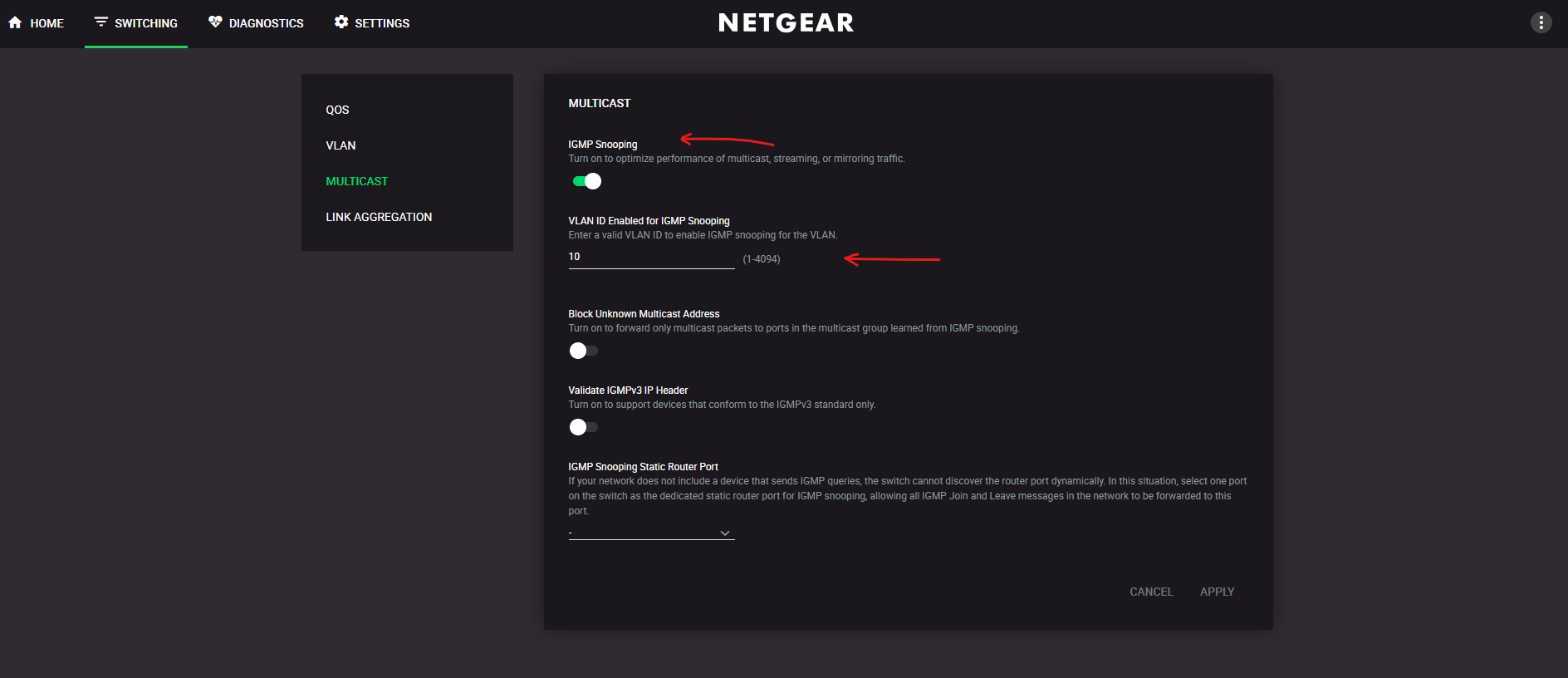
In my lab, all multicast sources, the FFmpeg streaming VM, and the Windows VLC receivers are located in the same VLAN. Therefore, IGMP Snooping needs to be enabled for this VLAN on the physical switches as well, so the switches can learn which ports have receivers for the multicast group instead of flooding the traffic to all ports.
As explained in the previous section, IGMP Snooping relies on an IGMP Querier to periodically refresh multicast group memberships. Since IGMP/MLD Snooping is enabled on the vSphere Distributed Switch (VDS) in this lab, VMware automatically provides the required IGMP Querier for the VLAN.
With IGMP Snooping disabled, the physical switch cannot track which specific ports are interested in the
239.1.1.1multicast group.Because physical switches cannot naturally ‘learn’ multicast destination MAC addresses in their standard CAM (Content Addressable Memory) tables, the incoming multicast stream from the FFmpeg streaming VM is treated as unknown multicast. A physical switch builds its CAM table entirely by looking at the Source MAC address of frames entering its physical ports. A VMware vSwitch (VSS or VDS) doesn’t just passively listen to traffic to learn MAC addresses; it has a direct, software-defined relationship with the Guest OS via the hypervisor.
As a result, the switch blindly floods the stream to all ports within the VLAN, exactly like broadcast traffic, forcing every unjoined workload on that VLAN to process and discard the unwanted packets.
With IGMP Snooping enabled, the FFmpeg streaming VM continues to send the multicast stream to 239.1.1.1 regardless of whether any receivers exist. If no client has joined the multicast group, the switch does not forward the packets to any access port and simply discards them after they arrive on the ingress port. Once a client joins the group, the switch forwards the multicast traffic only to the corresponding switch port(s).
This behavior is exactly what makes multicast so efficient: the sender is completely unaware of the receivers, while the network infrastructure determines where the traffic should be forwarded.
Inside vSphere, virtual switches handle this differently than a physical switch with snooping disabled (which blindly floods multicast to the entire VLAN like broadcast traffic).
A vSphere Standard Switch (VSS) uses its hypervisor-level insight to perform basic Layer 2 MAC filtering to drop traffic for non-receivers; however, because it lacks Layer 3 awareness, it cannot differentiate between different IP streams that share overlapping multicast MAC addresses.
VSS → basic Layer 2 MAC filtering
When multiple IPv4 multicast streams (like239.1.1.1and239.129.1.1) are transmitted, they map down to the exact same Layer 2 destination MAC address (01:00:5e:01:01:01) due to the way IP-to-MAC mathematical conversion drops 5 bits of the IP address.Because a basic vSphere Standard Switch operates strictly at Layer 2, it only looks at this final MAC address and cannot inspect the underlying Layer 3 IP headers. As a result, if a VM joins just one of those streams, the VSS is forced to deliver both video streams to that VM’s port because it cannot tell them apart by their MAC address alone.
By contrast, a vSphere Distributed Switch (VDS) with IGMP Snooping brings true Layer 3 intelligence directly into the hypervisor, allowing it to precisely map exact multicast IP streams to specific virtual ports, eliminating MAC address collisions entirely and ensuring optimal traffic isolation.
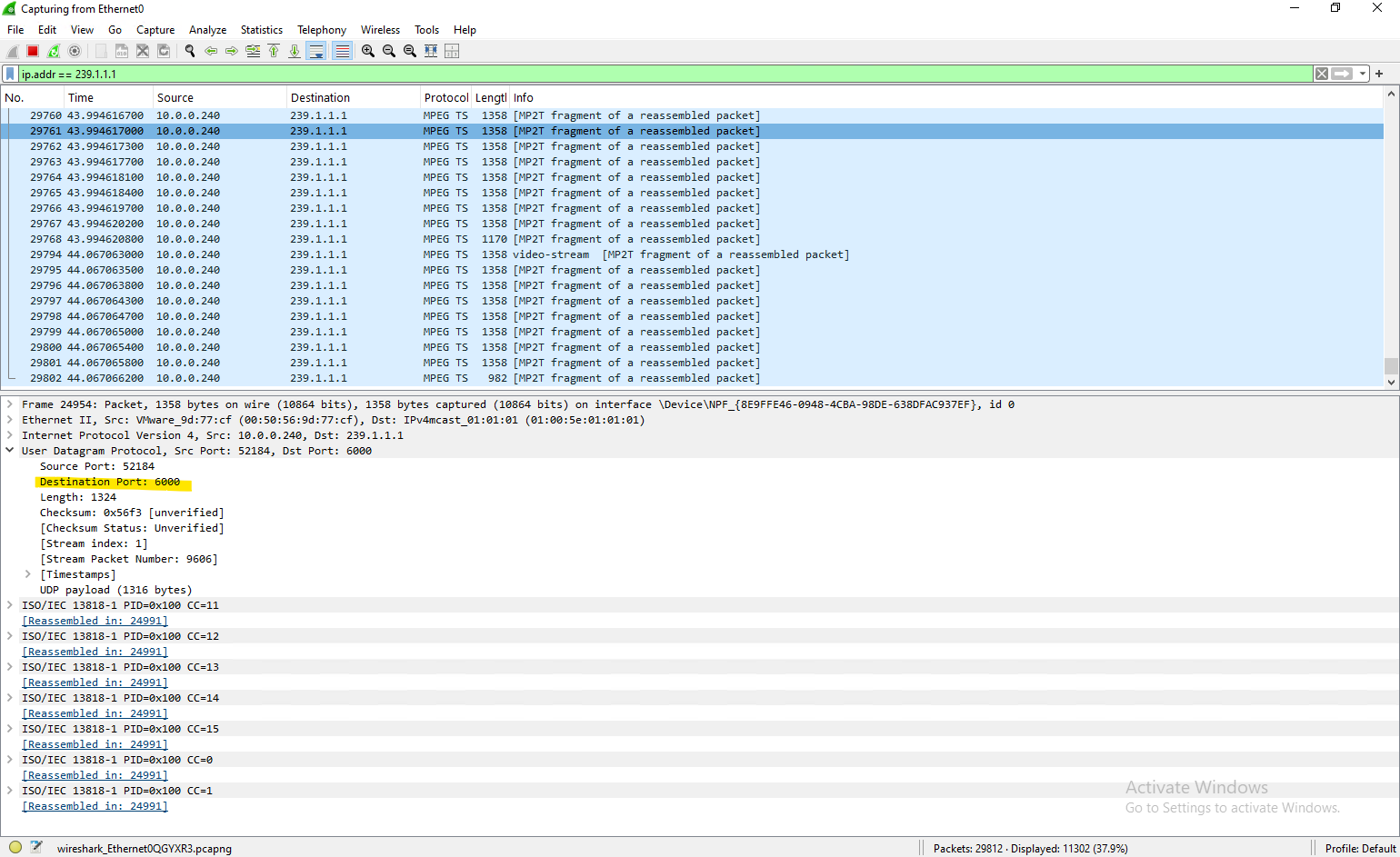
On the receiver VMs that have joined the multicast group, we can verify that the multicast stream is being received by capturing the network traffic with Wireshark and applying the filter ip.addr == 239.1.1.1.
We should observe a continuous stream of MPEG Transport Stream (MP2T) packets as shown below, displayed as “MP2T fragment of a reassembled packet”, confirming that the multicast video is successfully arriving at the client.
Wireshark and Promiscuous Mode on the Same ESXi Host
During testing, I noticed an interesting behavior when capturing traffic with Wireshark on a VM that had not joined the multicast group.
Although IGMP/MLD Snooping was enabled (by default) on the vSphere Distributed Switch (VDS), Wireshark still displayed the multicast stream whenever both the sender and the non-receiver VM resided on the same ESXi host, even though the non-receiver VM never sent an IGMP join request and should not have seen any traffic on its virtual network adapter.
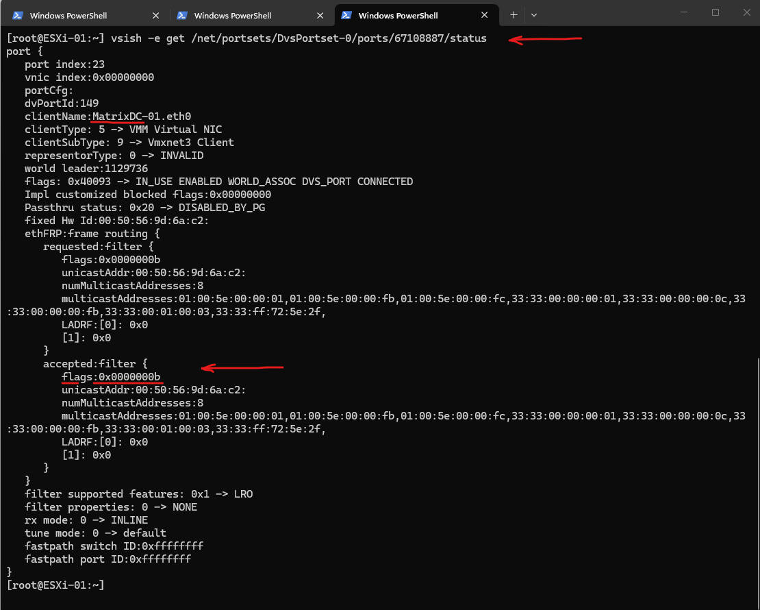
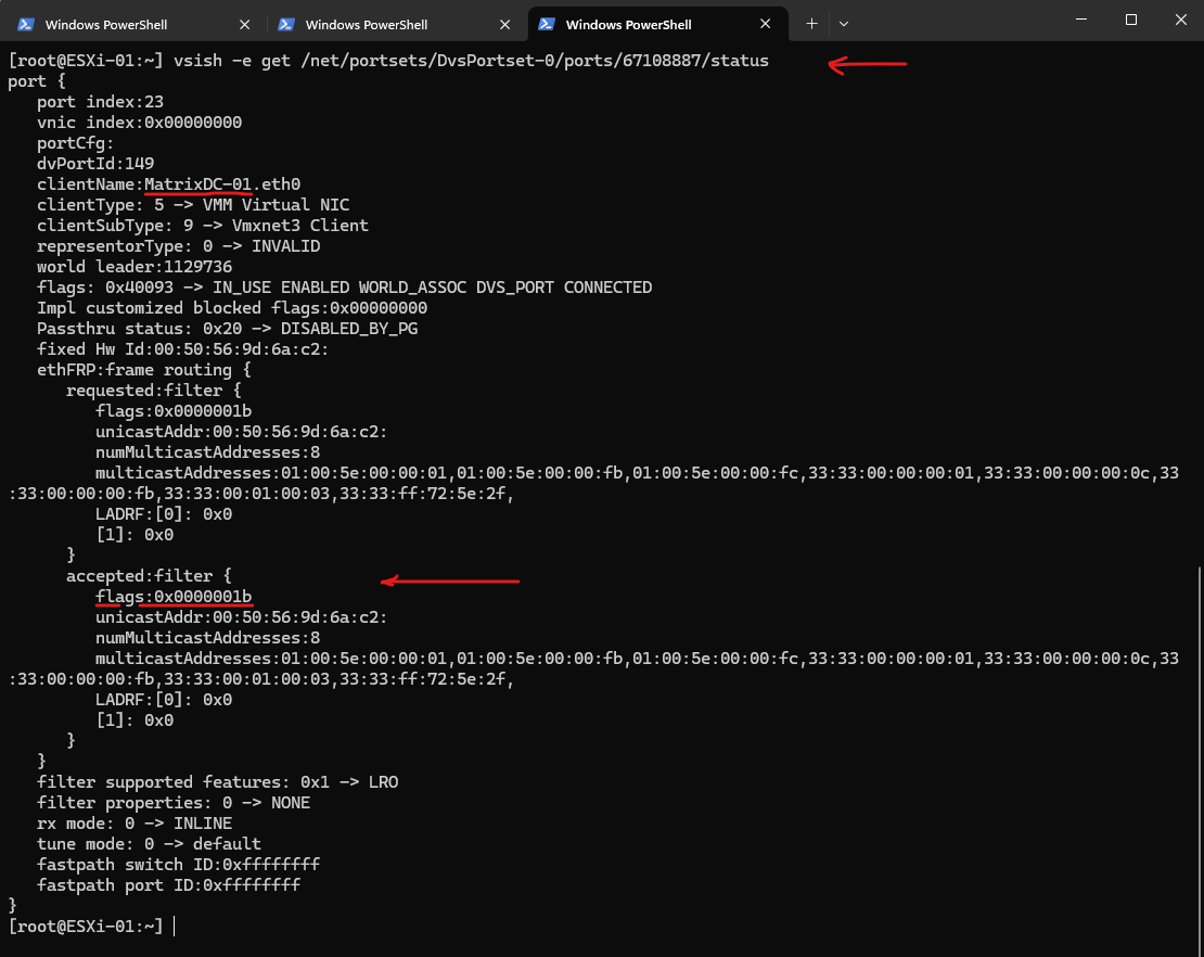
At first glance, this appeared to contradict the expected behavior of IGMP Snooping. However, a closer investigation using vsish on the ESXi host revealed that starting a Wireshark capture temporarily changed the receive filter of the VM’s virtual network adapter from 0x0000000b to 0x0000001b, enabling Promiscuous Mode.
As a result, the ESXi virtual switch intentionally mirrored the local multicast traffic to the VM for packet capture, even though the guest operating system had not joined the multicast group.
How promiscuous mode works at the virtual switch and portgroup levels
A virtual machine, Service Console or VMkernel network interface in a portgroup which allows use of promiscuous mode can see all network traffic traversing the virtual switch.
By default, a guest operating system’s virtual network adapter only receives frames that are meant for it. Placing the guest’s network adapter in promiscuous mode causes it to receive all frames passed on the virtual switch on that host only that are allowed under the VLAN policy for the associated port group
Source: https://knowledge.broadcom.com/external/article/324553/how-promiscuous-mode-works-at-the-virtua.html
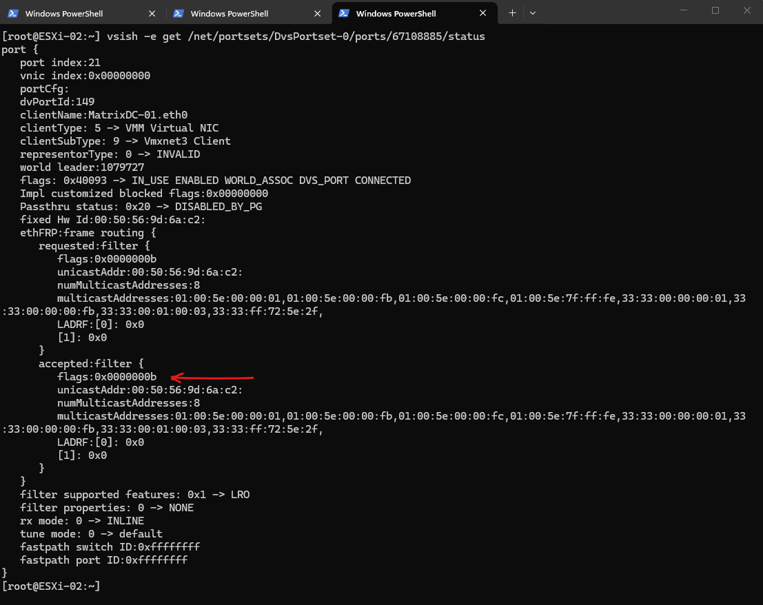
Before starting Wireshark, the VMXNET3 adapter uses its default receive filter (flags: 0x0000000b), which does not include Promiscuous Mode. In this state, the virtual switch forwards only traffic matching the VM’s registered receive filters and multicast memberships.
To inspect the receive filter configuration of a VM by using
vsish, you first need to determine the VM’s corresponding virtual port number on the vSphere Distributed Switch. If you are unsure how to obtain it, refer to the Troubleshooting section further down, where the process is described step by step.The
vsishcommand must be executed directly on the ESXi host where the VM is currently running. Therefore, first connect to that ESXi host and use theesxclito determine the VM’s corresponding virtual port number before inspecting the port status withvsish.They are two different stages of the receive filter:
requested:filter = what the guest OS / VMXNET3 driver requested.
accepted:filter = what ESXi actually programmed for the virtual NIC after applying its own policy.
Normally they are identical, as in our output.
[root@ESXi-01:~] vsish -e get /net/portsets/DvsPortset-0/ports/<PORT-ID>/status
[root@ESXi-01:~] vsish -e get /net/portsets/DvsPortset-0/ports/67108887/status
After starting Wireshark, the receive filter changes from flags: 0x0000000b to flags: 0x0000001b.
The additional
0x0010flag enables Promiscuous Mode, causing the ESXi virtual switch to forward all traffic traversing the local virtual switch to the VM for packet capture, including multicast traffic that the guest operating system has not joined.
[root@ESXi-01:~] vsish -e get /net/portsets/DvsPortset-0/ports/<PORT-ID>/status
[root@ESXi-01:~] vsish -e get /net/portsets/DvsPortset-0/ports/67108887/status
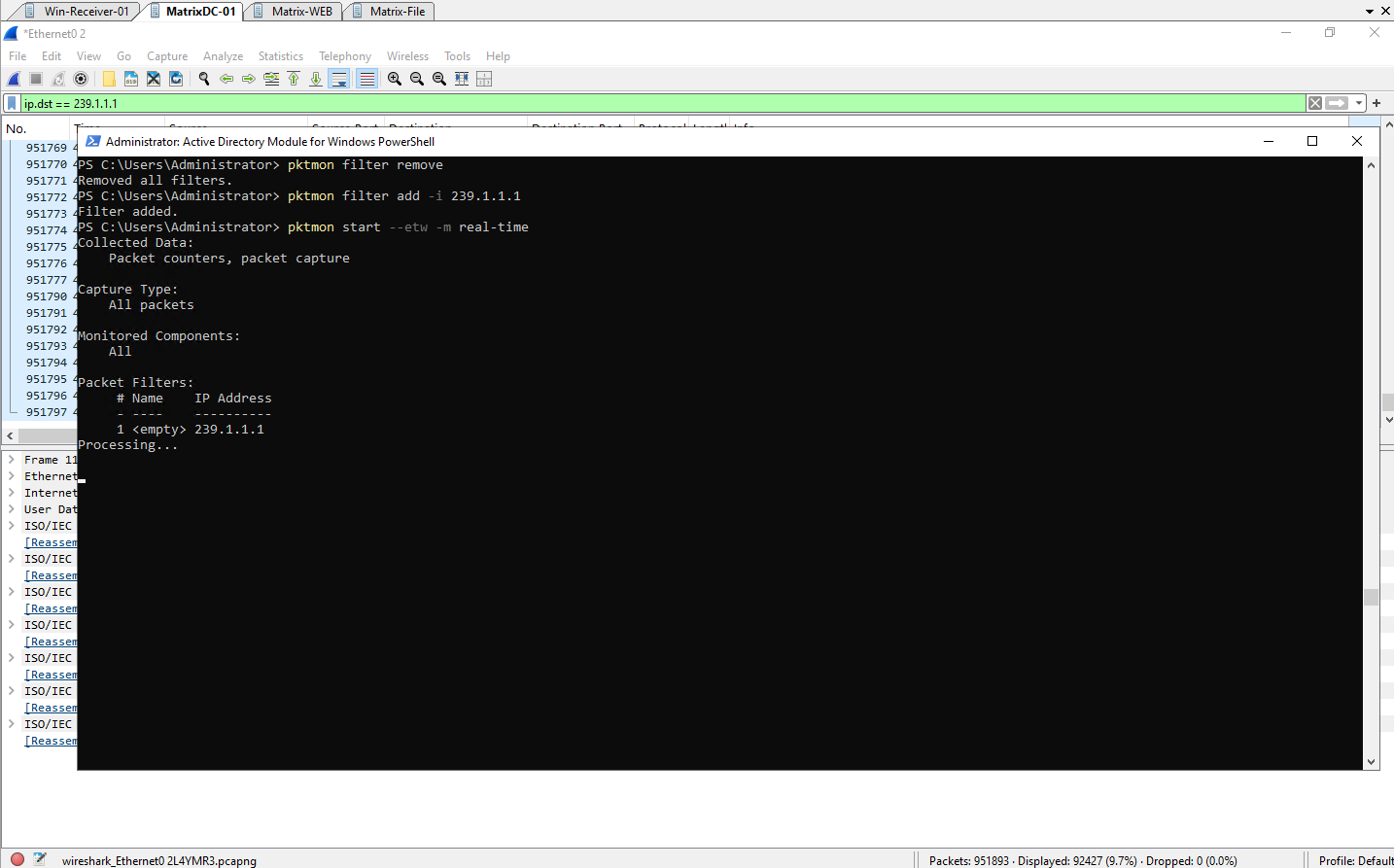
To further validate the observed behavior, I also captured the traffic by using PktMon, which monitors packets processed by the Windows networking stack rather than a packet capture driver such as Npcap. This makes it a useful tool to verify whether the guest operating system actually receives and processes the multicast traffic.
It is important to understand that Wireshark and PktMon observe network traffic at different layers. Wireshark uses Npcap, which installs an NDIS filter driver to capture packets as they pass through the network adapter driver, before they are handed to the Windows networking stack.
PktMon, on the other hand, captures packets that have already been indicated to and processed by the Windows networking stack. As a result, Wireshark may display packets that never reach the operating system, whereas PktMon reflects only the traffic actually delivered to the Windows networking stack.
Before starting Wireshark,
pktmonconfirms that the Windows networking stack does not receive any packets for the multicast group239.1.1.1, demonstrating that the VDS IGMP/MLD Snooping feature successfully prevents the stream from being delivered to the non-receiver VM.
PS> pktmon filter remove
PS> pktmon filter add -i 239.1.1.1
PS> pktmon start --etw -m real-time
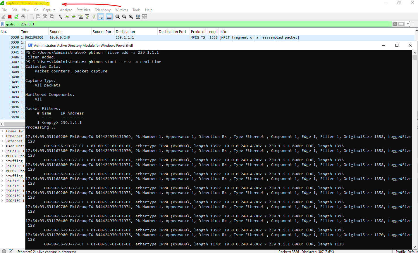
After starting Wireshark, Npcap requests Promiscuous Mode for the virtual network adapter, causing the VMXNET3 receive filter to change from 0x0000000b to 0x0000001b. ESXi honors this request by mirroring local traffic to the VM for packet capture, allowing multicast traffic for 239.1.1.1 to become visible even though the guest operating system has not joined the multicast group.
As already mentioned, Wireshark uses Npcap, which installs an NDIS filter driver to capture packets as they pass through the network adapter driver, before they are handed to the Windows networking stack.
The Network Driver Interface Specification (NDIS) is an application programming interface (API) for network interface controllers (NICs).
PktMon reports the multicast packets with the drop reason “Not locally destined”. This indicates that the packets reached the guest’s networking stack but were discarded because the VM had not joined the multicast group.
More about the pktmon utility you will find in my following post.
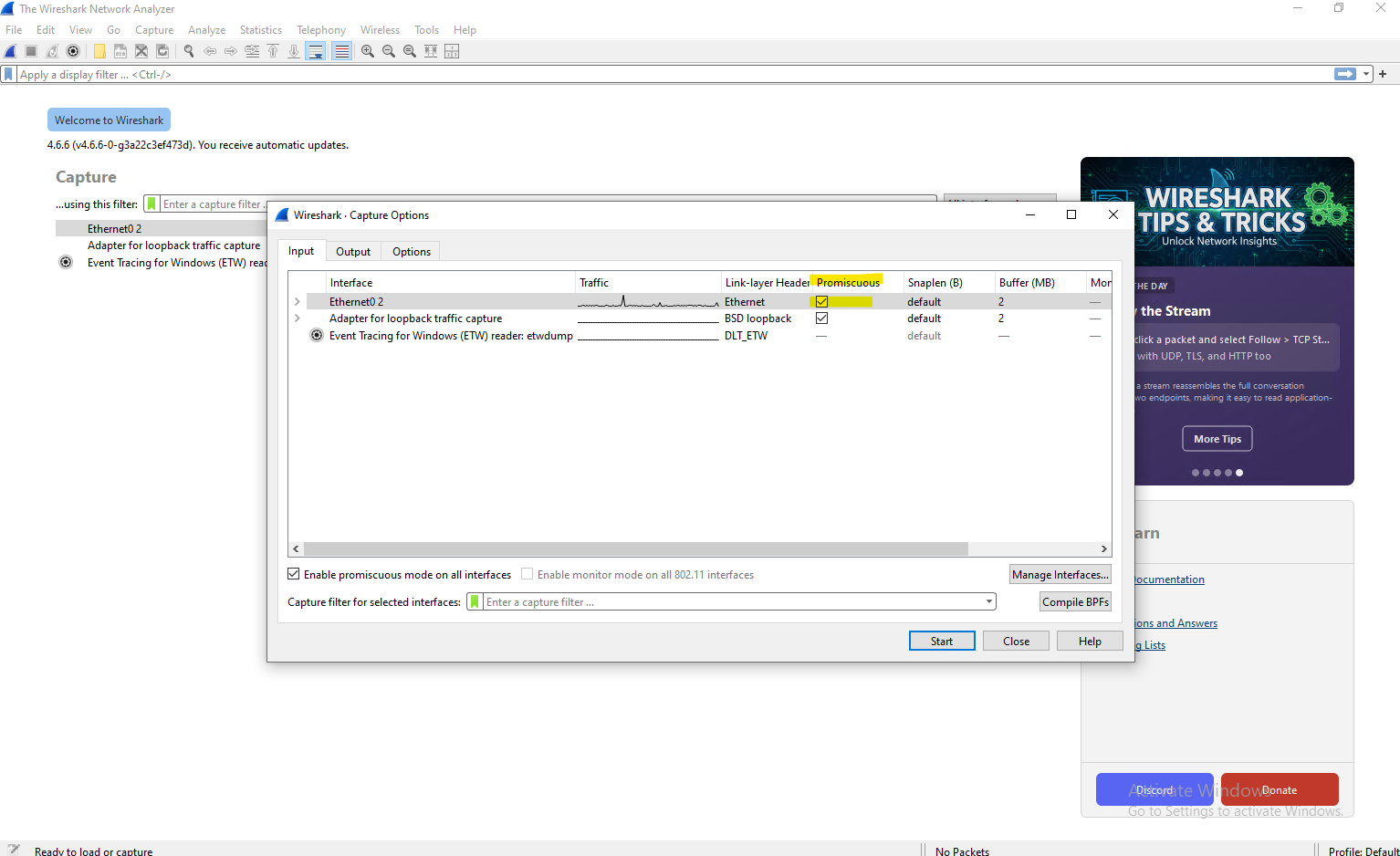
To continue analyzing traffic with Wireshark without triggering this virtual switch behavior, we must explicitly disable Promiscuous Mode in its capture options so the VMXNET3 adapter maintains its strict filtering.
By default, Wireshark enables Promiscuous Mode on the main network interface, which on a physical switch will still only show packets that actually arrive at that specific physical port.
However, when capturing traffic on a VMware vSwitch, this mode forces the ESXi host to actively deliver all local traffic traversing that virtual switch straight to the VM’s virtual port, regardless of whether it was originally destined for it.
To prevent this virtual switch behavior from skewing packet analysis, we must explicitly disable Promiscuous Mode within Wireshark’s interface settings before starting a capture.
This ensures that the VMXNET3 adapter maintains its strict hardware filtering flags, allowing the virtual distributed switch to isolate multicast traffic exactly as intended.
How promiscuous mode works at the virtual switch and portgroup levels
https://knowledge.broadcom.com/external/article/324553/how-promiscuous-mode-works-at-the-virtua.htm
Below uncheck Promiscuous Mode on the main network interface (VMXNET3 adapter) used to capture traffic.
Testing with a vSphere Standard Switch (VSS)
So far, all multicast tests were performed by using a vSphere Distributed Switch (VDS) with IGMP/MLD Snooping enabled. To better understand the architectural benefits of advanced multicast filtering, I repeated the same tests by using a vSphere Standard Switch (VSS).
Because a VSS does not provide native IGMP Snooping, it falls back to a Basic Filtering Mode that relies strictly on Layer 2 Multicast MAC address tracking rather than intelligent Layer 3 IP inspection.
💡 Note: No IGMP Querier is required when using a vSphere Standard Switch (VSS). Unlike IGMP Snooping, Basic Multicast Filtering does not rely on periodically refreshed multicast group memberships. You only need to consider an IGMP Querier if multicast traffic leaves the ESXi host and traverses physical switches with IGMP Snooping enabled.
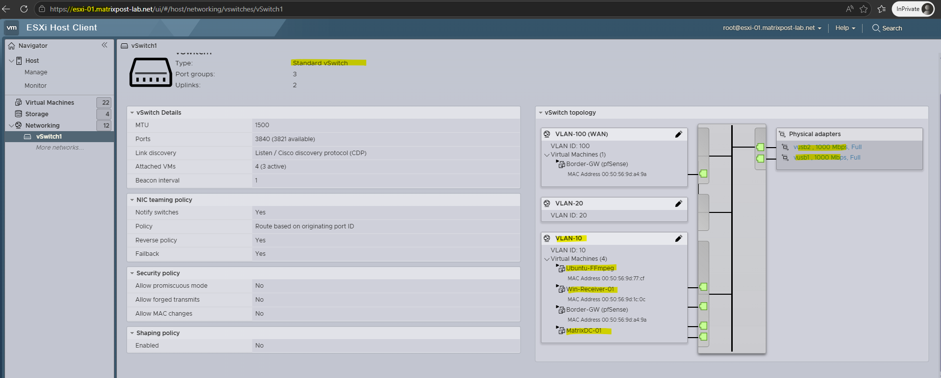
I will now switch one of the receiver VMs to use a vSphere Standard Switch (VSS), finally in the same VLAN ID 10 as before with the vSphere Distributed Switch (VDS).
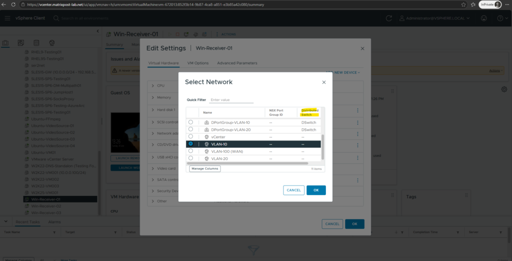
Further the same for a non-receiver VM (my DC).
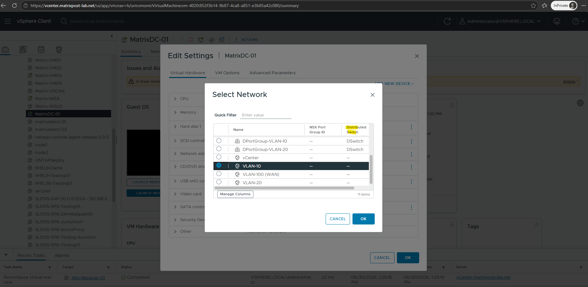
Also for the video source VMs and streaming server VM, I will need to change to a a vSphere Standard Switch (VSS). All VMs use already the new VMXNET3 virtual network adapter
Because the physical uplinks will be migrated from the VDS to the VSS below to test the behavior, all virtual machines should ideally be moved over to the new switch configuration to maintain external connectivity.
However, since this architectural change is only temporary for the duration of this lab environment, I will limit the migration strictly to the multicast lab VMs, including the receiver VMs, video source and streaming receiver VMs.
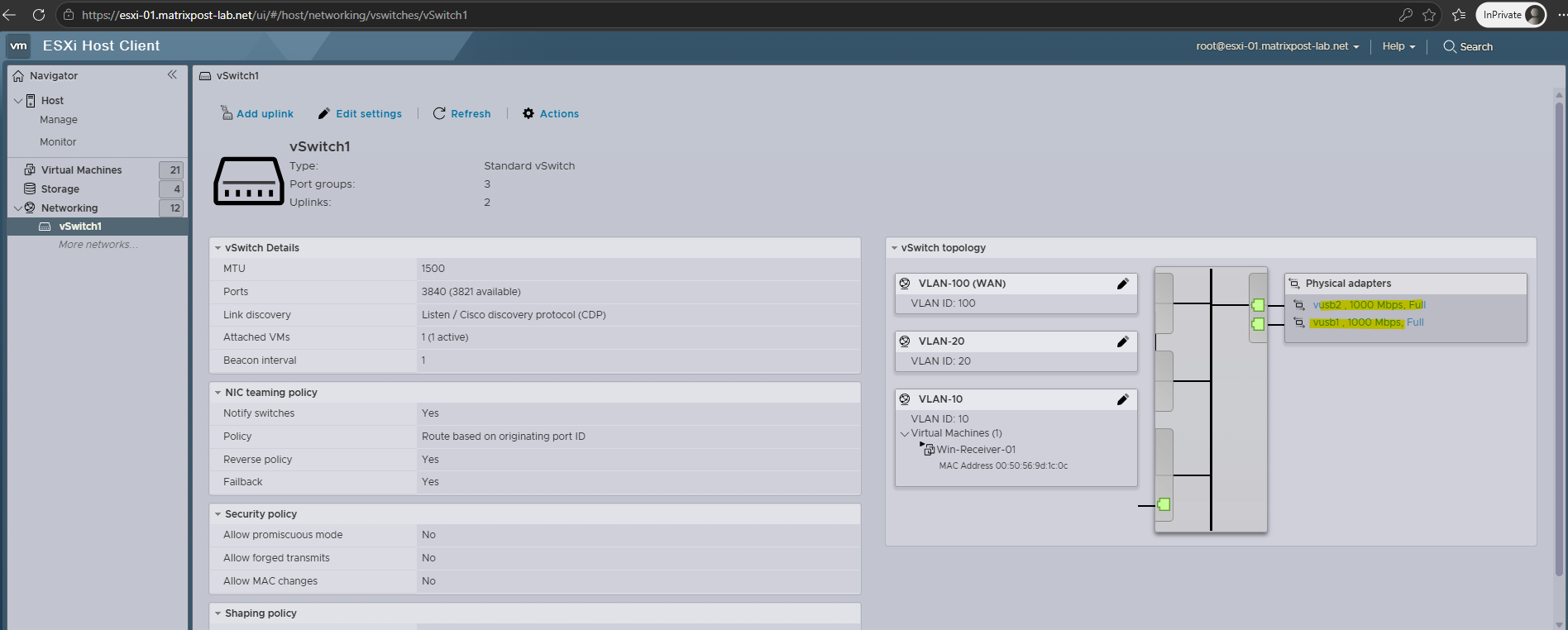
To switch from a VDS to a VSS back, we also need to first remove the physical uplinks from the VDS in vSphere and then add it to the VSS on each ESXi host.
More about migrating from vSphere Standard Switch (VSS) to vSphere Distributed Switch (VDS) and back you will find in my following post.
With all virtual machines in the lab now connected to a vSphere Standard Switch (VSS), we can take a closer look at how multicast traffic behaves in an environment without IGMP/MLD Snooping.
Since both the multicast source and the non-receiver VM were running on the same ESXi host, the multicast traffic remained entirely within the virtual switch and never traversed the physical network.
As a result, IGMP Snooping on the physical switches could not prevent the local multicast flooding or MAC-aliasing issues observed on the vSphere Standard Switch (VSS), which must rely solely on its own internal Basic Filtering Mode.
Here is a quick visual map for the “flooding” risk in Basic Mode on a vSphere Standard Switch (VSS).
Imagine you have three multicast streams running on your network, and your VM only wants Stream 1:
- Stream 1 (IP:
239.1.1.1) ➡️ Maps to Multicast MAC:01:00:5e:01:01:01(The stream my client receiver VMs want to receive) - Stream 2 (IP:
224.1.1.1) ➡️ Maps to Multicast MAC:01:00:5e:01:01:01(An exact duplicate MAC!) - Stream 3 (IP:
224.1.1.9) ➡️ Maps to Multicast MAC:01:00:5e:01:01:09
In Basic Mode (VSS):
- Your VM joins Stream 1 (
239.1.1.1): The VMXNET3 adapter tells the vSwitch, “Hey, please let traffic for MAC01:00:5e:01:01:01through to my port.” - The Result: * Stream 3 is blocked perfectly because its MAC is different.
- Stream 1 arrives perfectly, just as you wanted.
- Stream 2 (
224.1.1.1) is accidentally flooded to your VM. Because it shares the exact same MAC, the vSwitch sees a match and pushes it down the port. Your VM’s operating system now has to waste CPU cycles looking at the IP header, saying “Wait, I didn’t ask for224.1.1.1,” and throwing it away.
This is exactly why high-throughput multicast environments (like IP video streaming or financial market data feeds) completely abandon VSS and rely strictly on VDS with IGMP Snooping, so that Stream 2 is blocked at the door, keeping the VM’s network pipe perfectly clean.
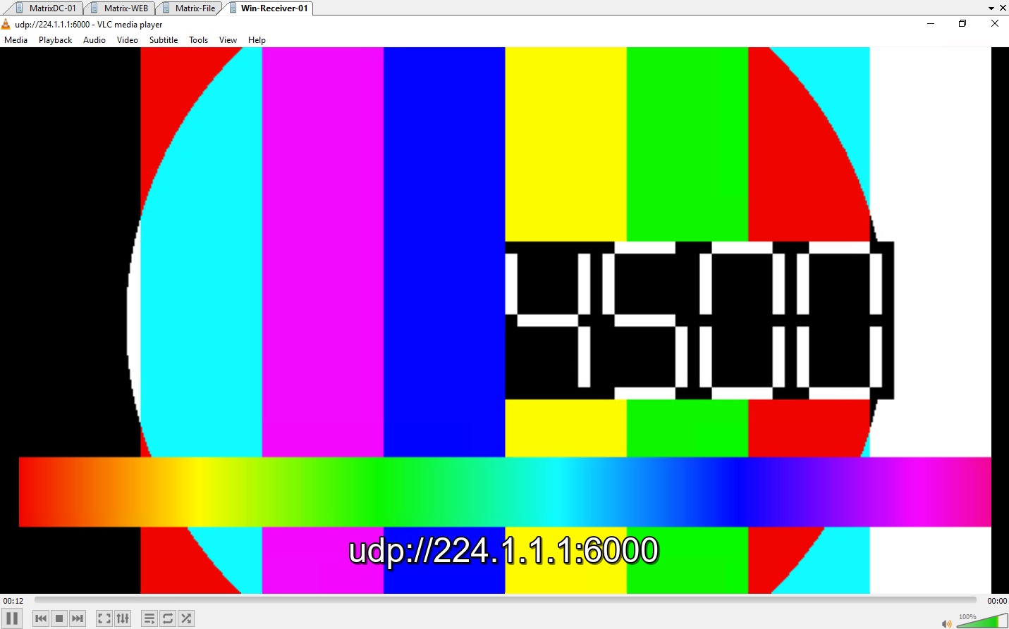
To demonstrate the real-world impact of MAC-aliasing, I attempted to spin up a second simultaneous FFmpeg stream on my source VM targeting 224.1.1.1:6000 to collide with the active 239.1.1.1:6000 stream.
To prevent the streaming server’s CPU from choking under the immense processing load of running two complex
xstackvideo matrix encodes simultaneously, I substituted the streams with a lightweight, built-in FFmpeg test pattern. This optimization dropped the processing overhead dramatically, allowing both streams to broadcast at full speed so we could cleanly observe the network packet behavior without hardware bottlenecks.
# first SSH session streaming to udp://239.1.1.1:6000
root@Ubuntu-FFmpeg:~# ffmpeg -re -f lavfi -i testsrc=size=640x360:rate=20 -c:v libx264 -preset ultrafast -tune zerolatency -b:v 500k -f mpegts "udp://239.1.1.1:6000?pkt_size=1316"


# second SSH session streaming to udp://224.1.1.1:6000
root@Ubuntu-FFmpeg:~# ffmpeg -re -f lavfi -i testsrc=size=640x360:rate=20 -c:v libx264 -preset ultrafast -tune zerolatency -b:v 500k -f mpegts "udp://224.1.1.1:6000?pkt_size=1316"
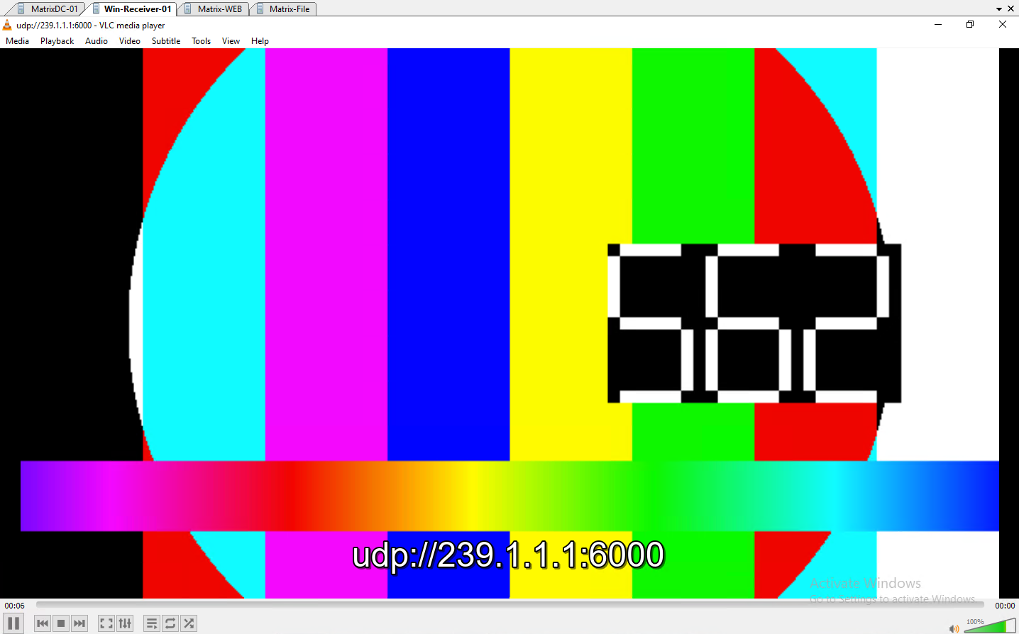
As seen below, the client VM’s VLC player smoothly decodes and displays the live synthetic test pattern arriving over
udp://239.1.1.1:6000. This confirms that despite the switch running in basic filtering mode, our intentional subscription channel remains fully functional.
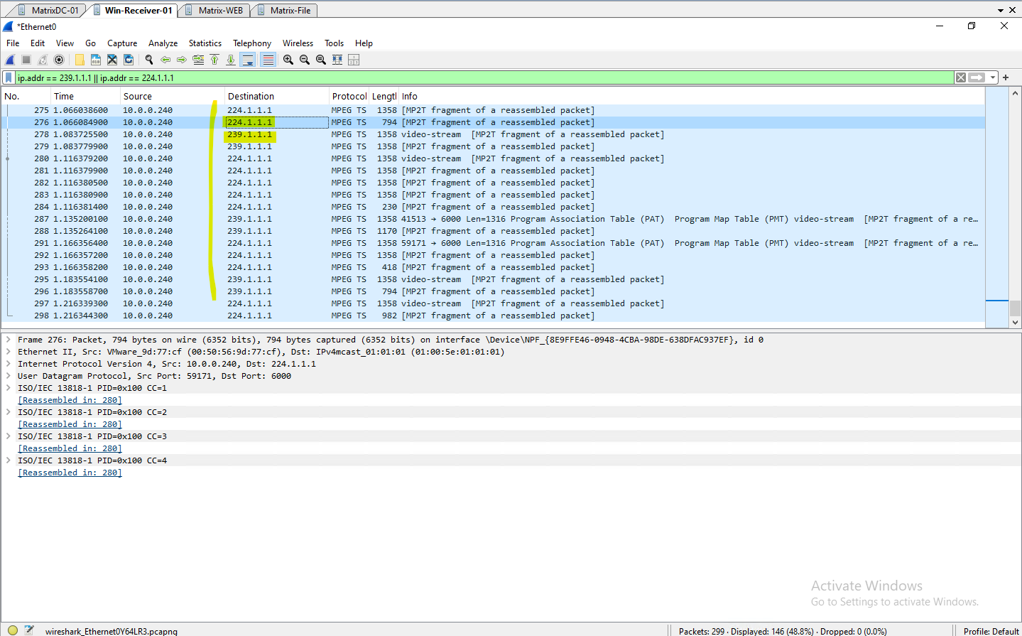
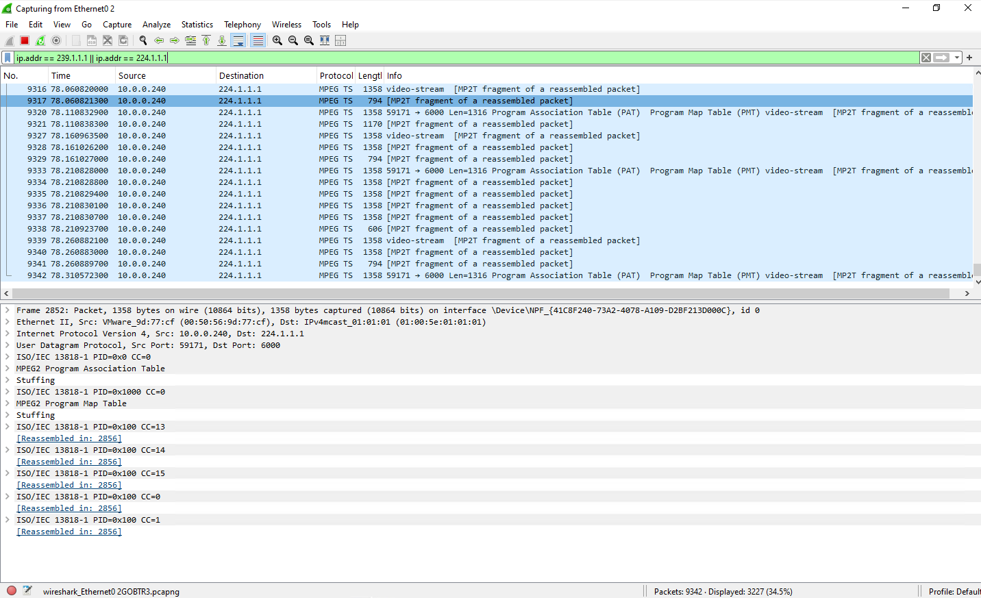
However, a peek under the hood via Wireshark reveals the true cost of MAC-aliasing on a VSS. Crucially, Wireshark must be started with Promiscuous Mode
disabledfor this test.Unlike a physical switch port where promiscuous mode simply allows you to sniff traffic naturally reaching your wire segment, VMware treats promiscuous mode entirely differently.
As outlined in Broadcom’s documentation and already mentioned further above, enabling it on a vSwitch port forces the virtual switch to act like a legacy hub, blindly duplicating all traffic traversing that entire virtual network segment directly to the guest VM.
By ensuring it is disabled in Wireshark, we prevent the VMXNET3 driver from triggering this “hub-mode” behavior on the hypervisor. This allows us to accurately capture the native filtering mechanics of the virtual switch, filling our screen with an alternating mix of both
239.1.1.1and224.1.1.1UDP packets simply because the vSwitch naturally leaked them down our port due to their identical Layer 2 destination MAC address.
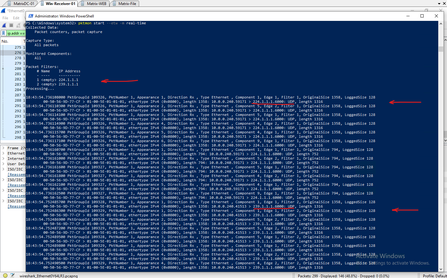
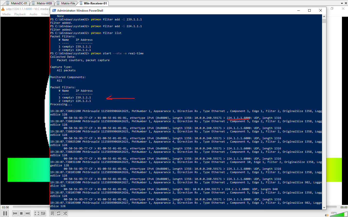
While configuring Wireshark with promiscuous mode
disabledgives us an accurate look at the wire, we can remove all doubt regarding driver configuration by cross-checking our results with Windows Packet Monitor (pktmon).By default,
pktmonoperates natively within the internal packet processing components of the OS networking stack. It has no mechanism to request promiscuous mode or alter the hypervisor’s Layer 2 delivery behavior. If the vSwitch filtering mechanics are working correctly,pktmonshould only see what is naturally dropped onto our virtual port.As the real-time capture log below proves, the vSwitch leak is plain as day. Without any promiscuous intervention, we capture alternating bursts matching both explicit filters.
After switching to a vSphere Distributed Switch (VDS) where IGMP Snooping is enabled, only the specific multicast traffic we explicitly subscribed to should hit the virtual network adapter, as seen in the Wireshark capture below.
By moving away from the Standard Switch’s blind Layer 2 forwarding, the VDS actively inspects the guest operating system’s IGMP membership reports to prune unrequested streams at the hypervisor layer.
This ensures that our VLC client smoothly receives the intended 224.1.1.1 test pattern while cleanly isolating our network adapter from any overlapping, aliased traffic.
With our VLC player switched to subscribe exclusively to the
224.1.1.1:6000stream, the Wireshark capture (with promiscuous modedisabled) updates to show only the224.1.1.1multicast traffic hitting the interface.Because the other group is completely unsubscribed at the OS layer, the switch handles the isolated stream cleanly, ensuring no rogue packets leak onto our virtual adapter.
Also the real-time pktmon trace confirms that our virtual interface remains perfectly optimized. The capture outputs demonstrate that only the requested 224.1.1.1 packets successfully pass through the network driver components, leaving no trace of the unsubscribed traffic.
Why a Reboot is Mandatory When Swapping Switch Types
If you are hot-migrating a live VM between a vSphere Standard Switch (VSS) and a vSphere Distributed Switch (VDS), or vice versa, you will likely notice a strange “ghost memory” behavior.
Even after the migration wizard finishes, packet captures may still show the old switch’s filtering logic in effect until you completely reboot the guest OS.
This happens due to a deep caching misalignment between the ESXi hypervisor layers and the guest operating system’s network driver:
- The VMkernel Port State Cache: When a VM is moved between a VSS and a VDS, it isn’t just changing a cable; it is moving to an entirely different software switch fabric. A VDS with IGMP Snooping maintains active Layer 3 IP-to-port mapping tables in the host’s memory. When you migrate away from it, those granular multicast filter states can linger in the VMkernel’s active memory allocation until the virtual link-state is forcefully dropped and recreated.
- VMXNET3 Driver Ring Buffers: The paravirtualized VMXNET3 driver relies on a direct, high-speed memory-sharing ring buffer between the Windows kernel and the ESXi hypervisor. During a live migration, the driver keeps its active packet processing queues open to prevent network disruption. However, it does not automatically flush or re-negotiate its hardware multicast MAC address tables (
accepted:filterflags) down to the new switch fabric during a hot-swap.
Without a full system reboot, the guest OS continues to pass packets through a stale driver state, resulting in skewed testing results. Bouncing the guest OS forces the Windows TCP/IP stack to completely collapse its sockets, re-initialize the VMXNET3 virtual hardware registers, and register a perfectly clean set of multicast demands with the new vSwitch architecture.
Migrating to a vSphere Distributed Switch (VDS)
Since IGMP/MLD Snooping is only available on a vSphere Distributed Switch (VDS), environments currently using a vSphere Standard Switch (VSS) must first migrate to a VDS to take advantage of this feature.
The complete migration process is covered step by step in my following post.
We can verify if IGMP/MLD snooping is enabled on the VDS by opening its settings in vSphere as shown below.
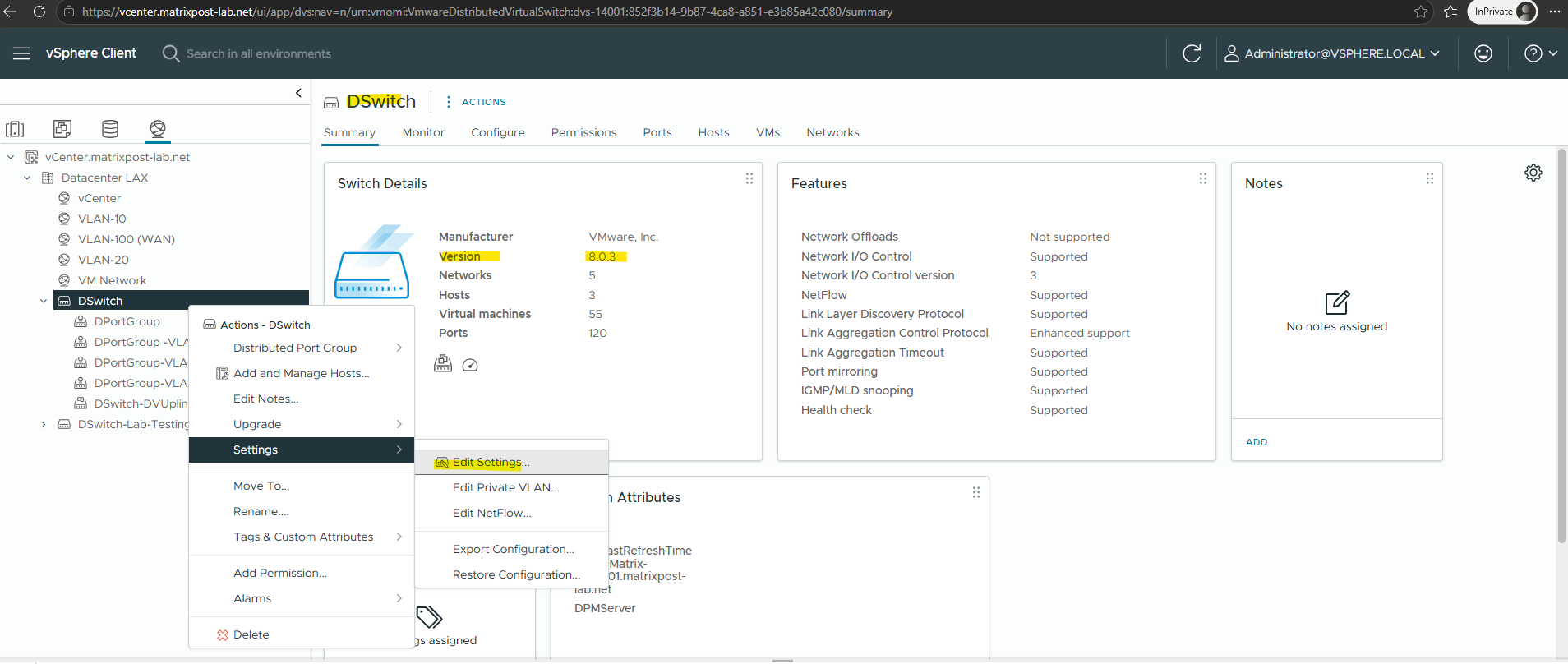
In addition to the default basic mode for filtering multicast traffic, vSphere Distributed Switch 6.0.0 and later releases support multicast snooping that forwards multicast traffic in a more precise way based on the Internet Group Management Protocol (IGMP) and Multicast Listener Discovery (MLD) messages from virtual machines.
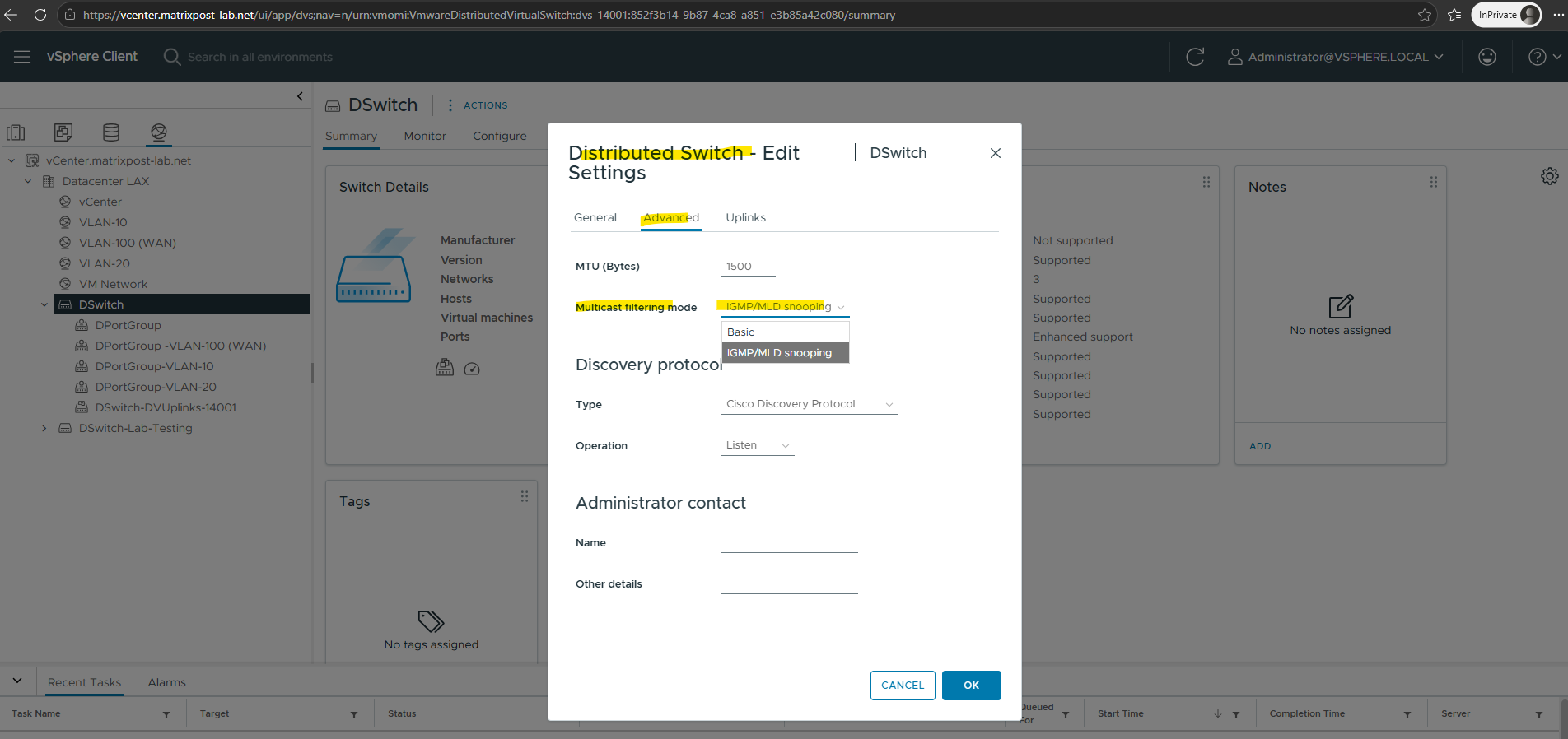
Multicast Listener Discovery (MLD) is the IPv6 equivalent of IGMP.
IGMP (Internet Group Management Protocol) → Used for IPv4 multicast.
MLD (Multicast Listener Discovery) → Used for IPv6 multicast.
Comparing VSS vs. VDS
Although both vSphere Standard Switch (VSS) and vSphere Distributed Switch (VDS) can forward multicast traffic, they differ significantly in how they handle multicast distribution.
The following table summarizes the key differences and highlights why a VDS is the preferred choice for multicast-intensive environments.
| Feature | vSphere Standard Switch (VSS) | vSphere Distributed Switch (VDS) |
|---|---|---|
| IGMP/MLD Snooping | ❌ Not supported | ✅ Supported |
| Unknown multicast traffic | Flooded to all ports | Forwarded only to interested ports |
| Bandwidth efficiency | Lower | Higher |
| Scalability | Suitable for small environments | Recommended for medium and large environments |
| Centralized management | ❌ Per host | ✅ Across all ESXi hosts |
| Configuration consistency | Manual | Centralized |
| Multicast optimization | None | IGMP/MLD Snooping |
| Physical switch dependency | More multicast reaches the physical network | Reduces unnecessary multicast leaving the host |
For small lab environments with only a few multicast streams, a vSphere Standard Switch (VSS) is often sufficient. However, for production environments or multicast-intensive workloads, a vSphere Distributed Switch (VDS) provides significant advantages by reducing unnecessary multicast flooding, improving bandwidth efficiency, and offering centralized management across all ESXi hosts.
Troubleshooting
Unexpected Multicast Flooding with the E1000E Virtual NIC
During testing, I observed different multicast behavior depending on the virtual network adapter type, even though IGMP/MLD Snooping was enabled on the vSphere Distributed Switch (VDS).
When the multicast source VM and a non-receiver VM were running on different ESXi hosts, the multicast traffic traversed the physical network and my NETGEAR switches on which also IGMP Snooping is enabled, correctly prevented delivery to VMs that had not joined the multicast group.
However, when both VMs resided on the same ESXi host, a VM using the legacy E1000E adapter still received all multicast traffic despite not having joined the group.
After replacing the adapter with VMXNET3, the VM only received multicast traffic for groups it had actually joined.
This behavior is explained by the receive filter configuration: the E1000E adapter requests the ALLMULTI receive mode, whereas VMXNET3 registers only the required multicast MAC addresses, allowing the VDS IGMP/MLD Snooping feature to filter multicast traffic as expected.
With the legacy E1000E adapter, the VM still received/captured multicast traffic for 239.1.1.1 even though it had not joined the group.
After replacing the adapter with VMXNET3, the same VM no longer saw the multicast stream, confirming that IGMP/MLD Snooping on the VDS was working as expected.
By using the following command we can see that our virtual machine had not joined the multicast group 239.1.1.1.
PS> netsh interface ip show joins
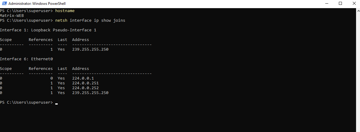
Although the VM had not joined the multicast group, the multicast traffic for 239.1.1.1 still reached the Windows networking stack when using the legacy E1000/E1000E adapter, as shown by the pktmon output below.
PS> pktmon filter remove
PS> pktmon filter add -i 239.1.1.1
PS> pktmon start --etw -m real-time
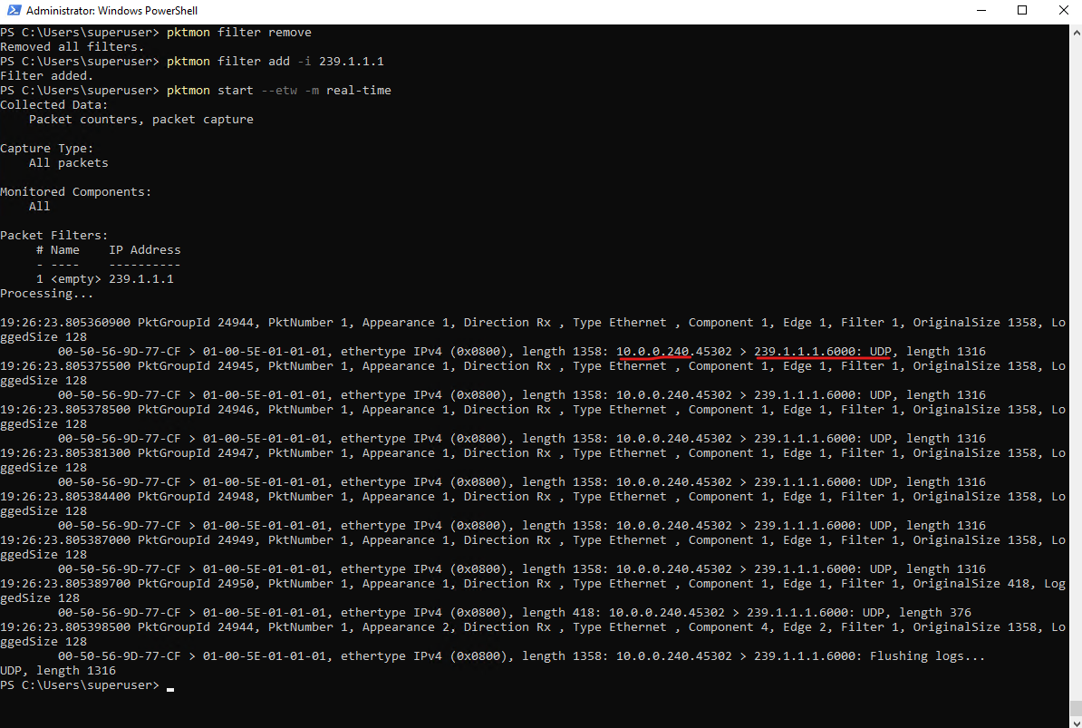
To identify the root cause, we’ll inspect the receive filter configuration of the VM’s virtual network adapter directly on the ESXi host by using vsish. The configured filter flags reveal how multicast traffic is handled by the virtual NIC.
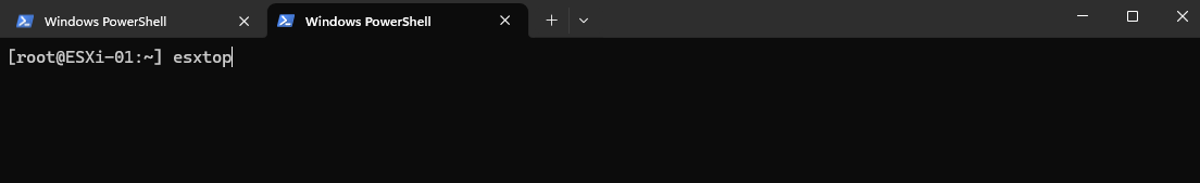
Before running the vsish command, first determine the VM’s virtual port number on the vSphere Distributed Switch. The easiest way to obtain this information is by using esxtop, which maps each virtual network adapter to its corresponding VDS port.
[root@ESXi-01:~] esxtop
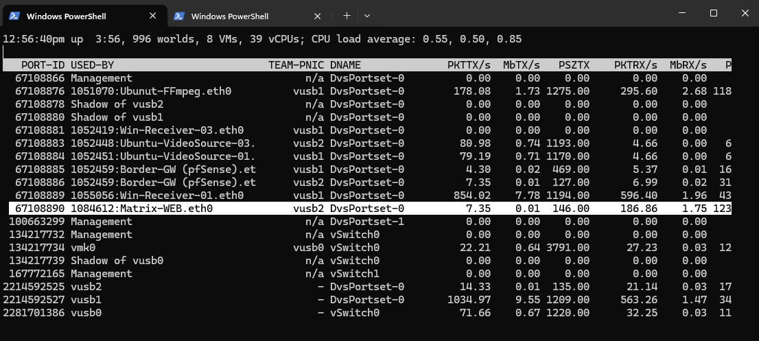
Press n to go to the network screen.
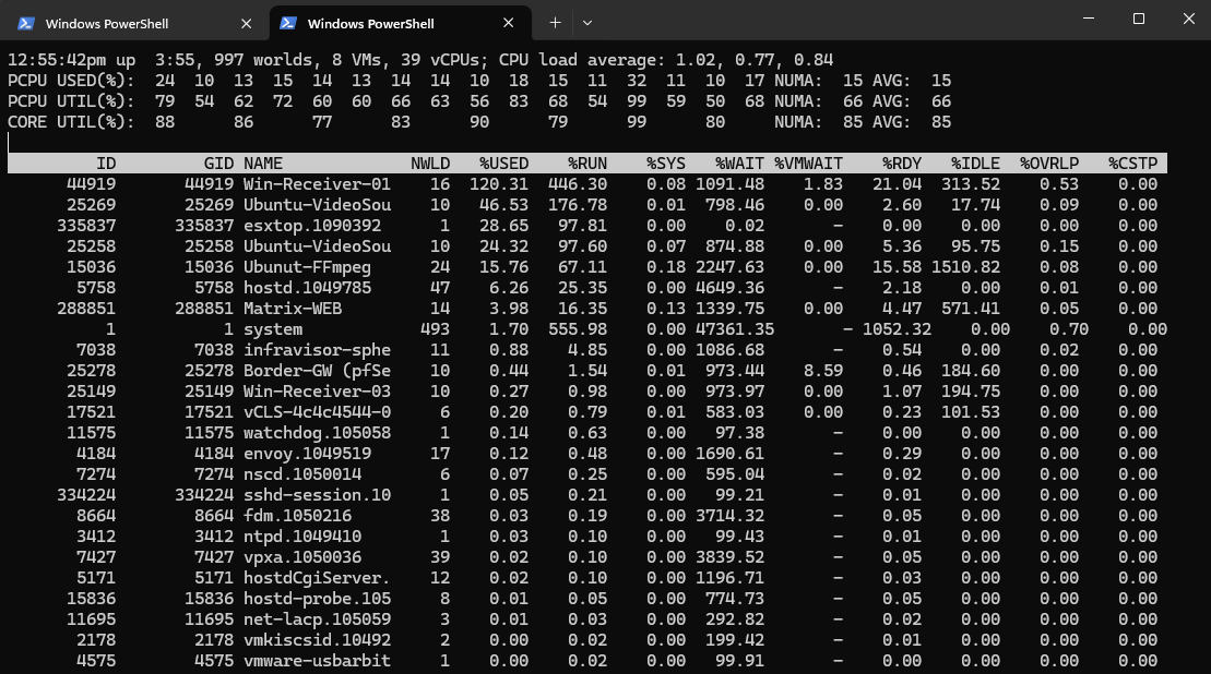
Look for your Windows VM’s name (in my case Matrix-Web) and note down its PORT-ID (in my case 67108890). Press q to exit.
To verify its current hardware filtering status on the virtual distributed switch, we can now query the port’s filter status using the following command:
Look closely under the
ethFRP:frame routingblock for theaccepted:filterflags:
[root@ESXi-01:~] vsish -e get /net/portsets/DvsPortset-0/ports/<PORT-ID>/status
[root@ESXi-01:~] vsish -e get /net/portsets/DvsPortset-0/ports/67108890/status
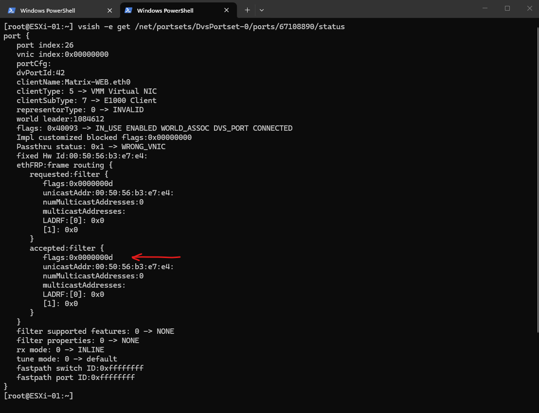
Look above at the flags value inside the accepted:filter block:
accepted:filter {
   flags:0x0000000d   <================== The filter status flags
As outlined in the Broadcom KB article, the network filter flags are evaluated using bitwise addition. If we break down our value of 0x000d (which is 13 in decimal), it translates to:
0x0001(ETH_FILTER_UNICAST) — Pass targeted traffic addressed to this VM’s MAC.0x0004(ETH_FILTER_ALLMULTI) — Pass ALL multicast frames.0x0008(ETH_FILTER_BROADCAST) — Pass broadcast traffic.
Because the legacy E1000 driver set 0x0004 (ALLMULTI), our ESXi host is forced to bypass IGMP Snooping optimization for this specific port. The host simply hands over every single local multicast packet it processes right down the line.
In contrast my MatrixDC-01 VM is using the VMXNET3 virtual network adapter.
The Flag is 0x0000000b (No ALLMULTI).
If you break down the math for 0x000b (11 in decimal), it translates to:
0x0001:ETH_FILTER_UNICAST(Pass normal directed traffic)0x0002:ETH_FILTER_MULTICAST(Pass ONLY the explicitly requested multicast addresses)0x0008:ETH_FILTER_BROADCAST(Pass broadcast traffic)
0x0004 (ETH_FILTER_ALLMULTI) is completely gone.
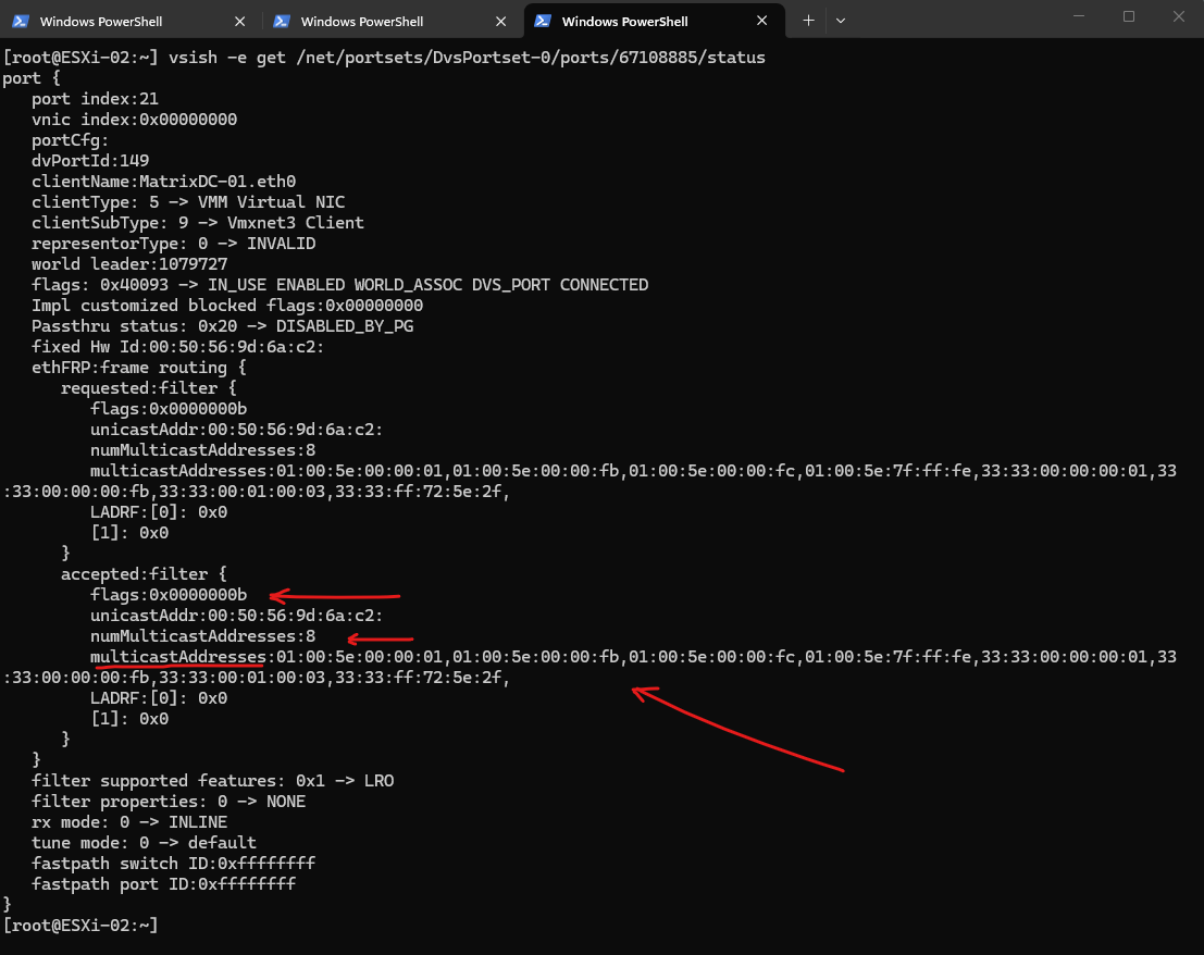
The VMXNET3 driver successfully registered exactly 8 specific multicast MAC addresses that Windows actually needs for background services.
If you map those MAC addresses back to their IP counterparts, you can see basic Windows networking operating exactly as intended:
33:33:... = Various IPv6 Neighbor Discovery and multicast groups.
01:00:5e:00:00:01 = 224.0.0.1 (All Hosts multicast)
01:00:5e:00:00:fb = 224.0.0.251 (mDNS / Bonjour)
01:00:5e:00:00:fc = 224.0.0.252 (LLMNR – Link-Local Multicast Name Resolution)
These hexadecimal flags represent network traffic filter states requested by a guest operating system, which the ESXi host applies to a virtual machine’s network interface. When combined through bitwise addition (such as 0x000f), they tell the vSwitch exactly which types of unicast, multicast, broadcast, or promiscuous packets are allowed to pass through to the VM.
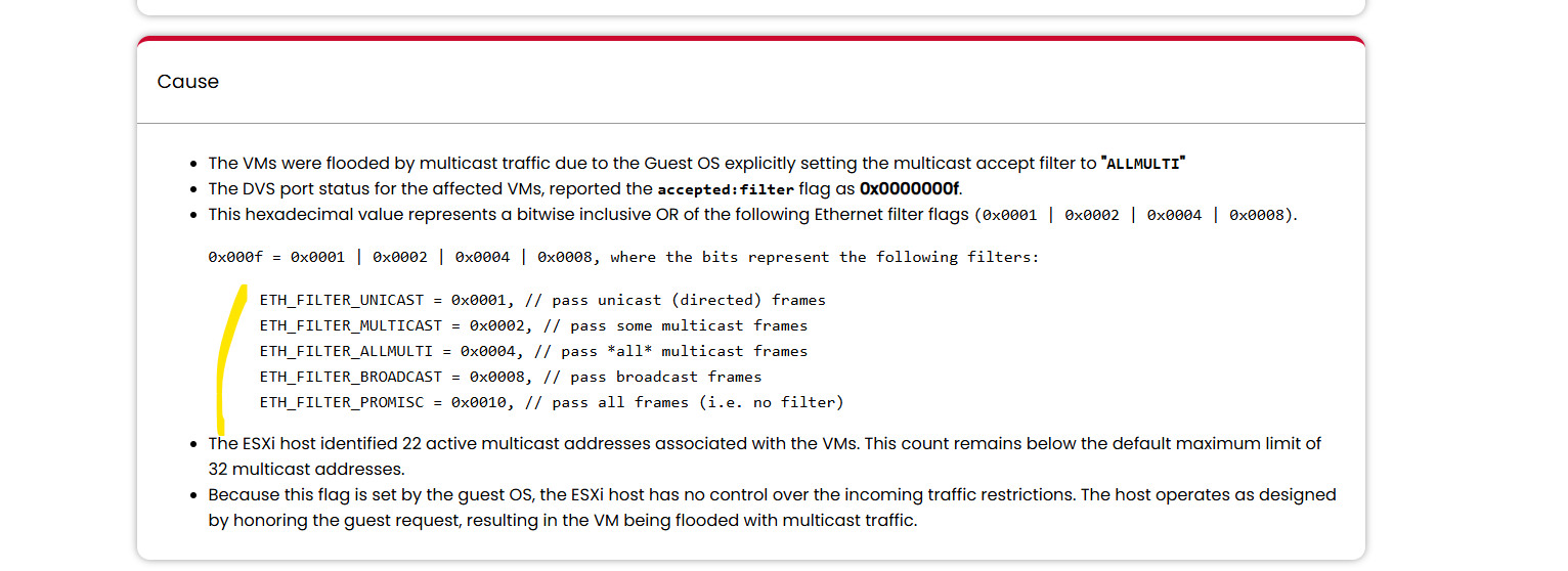
ETH_FILTER_UNICAST    = 0x0001
ETH_FILTER_MULTICAST  = 0x0002
ETH_FILTER_ALLMULTI   = 0x0004
ETH_FILTER_BROADCAST  = 0x0008
ETH_FILTER_PROMISC    = 0x0010
Source: https://knowledge.broadcom.com/external/article/376164/multicast-address-is-flooded-among-all-p.html
So far, all multicast traffic has remained within a single VLAN. In Part 2, we’ll take the next step and configure Multicast Across VLANs with pfSense and IGMP, demonstrating how multicast traffic can be routed between different VLANs while maintaining proper group membership.
Links
FFmpeg
https://www.ffmpeg.org/Enable Multicast Snooping on a vSphere Distributed Switch
https://techdocs.broadcom.com/us/en/vmware-cis/vsphere/vsphere/7-0/vsphere-networking/multicast-filtering/enable-igmp-mld-snooping-on-a-vsphere-distribtued-switch.htmlMulticast address is flooded among all ports when VMs placed under single ESXi host.
https://knowledge.broadcom.com/external/article/376164/multicast-address-is-flooded-among-all-p.htmlMulticast traffic fails between virtual machines when IGMP Snooping is enabled on VDS
https://knowledge.broadcom.com/external/article/442384/multicast-traffic-fails-between-virtual.htmlHow promiscuous mode works at the virtual switch and portgroup levels
https://knowledge.broadcom.com/external/article/324553/how-promiscuous-mode-works-at-the-virtua.htmlMulticast Filtering Modes
https://techdocs.broadcom.com/us/en/vmware-cis/vsphere/vsphere/7-0/vsphere-networking/multicast-filtering/mutlicast-filtering-modes.htmlMulticast Filtering in vSphere 6.0
https://portal.nutanix.com/page/documents/solutions/details?targetId=BP-2074-vSphere-Networking:multicast-filtering-in-vsphere-60.htmlBlender Downloads (Movies Big Buck Bunny)
https://download.blender.org/demo/movies/BBB/Blender Studio Big Buck Bunny
https://studio.blender.org/projects/big-buck-bunnySintel
https://studio.blender.org/projects/sintelSample files library – A completely free library of test files available to download without licensing restrictions. (Images, Video, Audio, …)
https://samplelib.com/
https://samplelib.com/sample-mp4.html