Software Defined Networking (SDN) with VMware NSX – Part 2: Configuring Tier-1, Tier-0 and Upstream Routing for the NSX Overlay Network
In Part 1, we built the NSX overlay network, prepared our ESXi hosts as Transport Nodes, created the first TenantA Overlay Segment, and verified the GENEVE-encapsulated Layer 2 traffic between our virtual machines.
In this second part, we will extend the overlay network with Layer 3 connectivity by deploying and configuring the required NSX Gateways. From the beginning, we will design the routing with multiple isolated tenants and VRFs in mind, allowing us later to use overlapping tenant IP address spaces while keeping their routing domains completely separated, including the north-south path toward an external VRF-aware router.
The Tier-1 Gateway provides routing for the tenant workload networks and acts as the Layer 3 gateway for our NSX overlay segments, while the Tier-0 Gateway provides the upstream routing layer between the NSX tenant environment and external networks.
Together, they form the routing path from our TenantA workloads through the NSX Edge toward the external VRF-aware router.
In my Microsoft HNV series, the corresponding routing concepts were introduced in Part 3, while the extension to isolated routing domains using Linux VRFs was demonstrated in Part 5.
With NSX, we will incorporate this multi-tenant routing design directly from the start and later extend the isolated routing domains through a VRF-aware external router for Internet connectivity.
In Part 3, we will build isolated multi-tenant overlay networks with overlapping IP address spaces, including identical host IP addresses, and demonstrate simultaneous Internet (WAN) access for both tenants.
In Part 4 we take a look at troubleshooting commands that help us understand and diagnose our NSX environment. We will also compare connection tracking and stateful firewall behavior across platforms such as Linux, Juniper, Cisco, Check Point, Fortinet and pfSense.
- Configure the NSX Gateway Infrastructure
- Configure VRF-Aware Upstream Routing
- Prepare the Parent Tier-0 for VRF Gateways
- Configure TenantA Workload Routing
- Configure the Ubuntu Router for Upstream Internet Connectivity
- Configure Internet Access and NAT for TenantA
- Links
Configure the NSX Gateway Infrastructure
Before we can provide Layer 3 connectivity for our overlay segments, we first need to build the required NSX gateway infrastructure. Unlike our standalone Layer 2 segment from Part 1, routed NSX networks use Tier-1 and Tier-0 Gateways to connect tenant workloads and eventually provide connectivity to the physical network.
Tier-1 Gateway: A logical NSX gateway primarily used for workload and tenant routing. It provides Layer 3 connectivity for NSX segments and can provide the default gateway for the connected workloads, for example
192.168.100.1for our TenantA subnet.Conceptually, this is similar to the tenant gateway we used with Microsoft HNV, where the first usable IP address of the virtual subnet is automatically used as the default gateway, and to Azure Virtual Networks, where Azure reserves the first usable address (
.1) of each subnet for the default gateway. With NSX, however, we explicitly configure the gateway address on the segment.Tier-0 Gateway: A logical NSX gateway that sits upstream of the Tier-1 Gateway and provides connectivity between the NSX environment and the external physical network. In my lab, the Tier-0 Gateway will ultimately connect through the NSX Edge Node toward a VRF-aware Ubuntu router at
10.0.0.1, which will provide the upstream routing while preserving the isolated routing domains required for our multi-tenant design.Both Tier-1 and Tier-0 are logical routing constructs managed by NSX; they should not be confused with the NSX Edge Node, which is the actual appliance providing the execution point for centralized routing and network services.
Conceptually, the NSX Edge Node corresponds to the SDN Gateway VM in our Microsoft HNV architecture shown in Part 3: it provides the appliance/data-plane execution point for centralized network services.
The Tier-1 and Tier-0 Gateways, in contrast, are logical routing constructs defined by the NSX control plane, comparable to the logical tenant and provider routing configuration that the Microsoft SDN control plane realizes on its infrastructure.
For my lab, we will build the gateway infrastructure with multiple isolated tenant routing domains in mind from the beginning. This will later allow TenantA and TenantB to use overlapping IP address spaces while their routing remains completely isolated.
Deploy an NSX Edge Node
Before configuring our Tier-0 Gateway and tenant routing architecture, we first need to deploy an NSX Edge Node. The Edge Node provides the centralized data-plane and network services required to connect our NSX overlay networks to the external physical network, which in my vSphere lab will ultimately be routed through the VRF-aware Ubuntu router at 10.0.0.1.
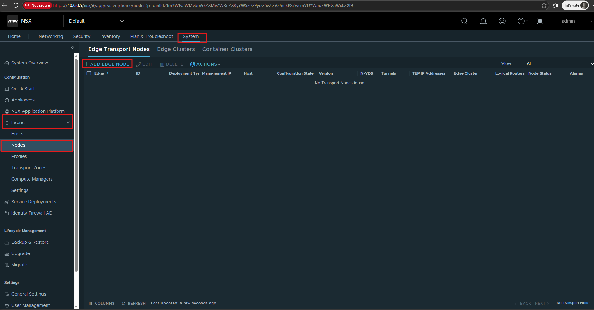
Go to: System → Fabric → Nodes → Edge Transport Nodes.
Click Add Edge Node to start deploying our first NSX Edge appliance.
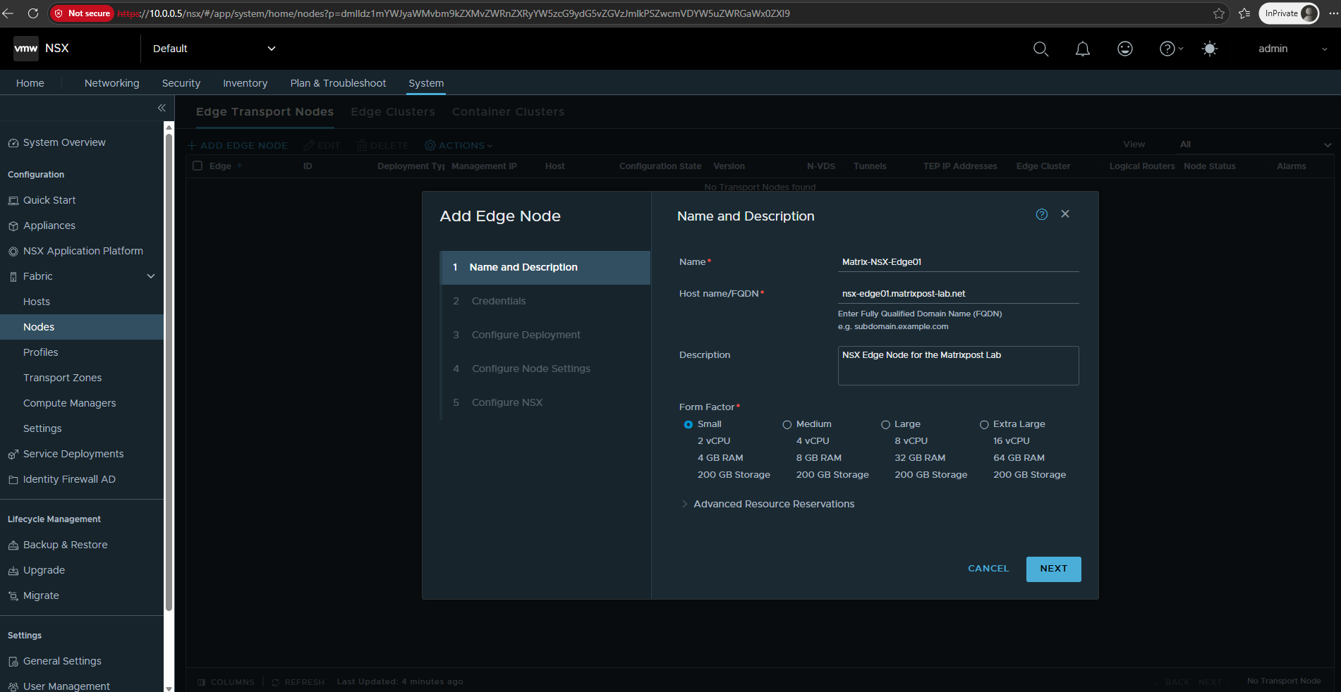
For the lab environment, I will use the Small form factor with 2 vCPUs, 4 GB RAM, and 200 GB storage, which is sufficient for demonstrating the NSX Tier-0/Tier-1 and multi-tenant routing architecture.
For my lab I will use:
- Name:
Matrix-NSX-Edge01 - Host name/FQDN:
nsx-edge01.matrixpost-lab.net - Description:
NSX Edge Node for the Matrixpost Lab - Form Factor: Small — 2 vCPU / 4 GB RAM / 200 GB
Then click NEXT to move to credentials.
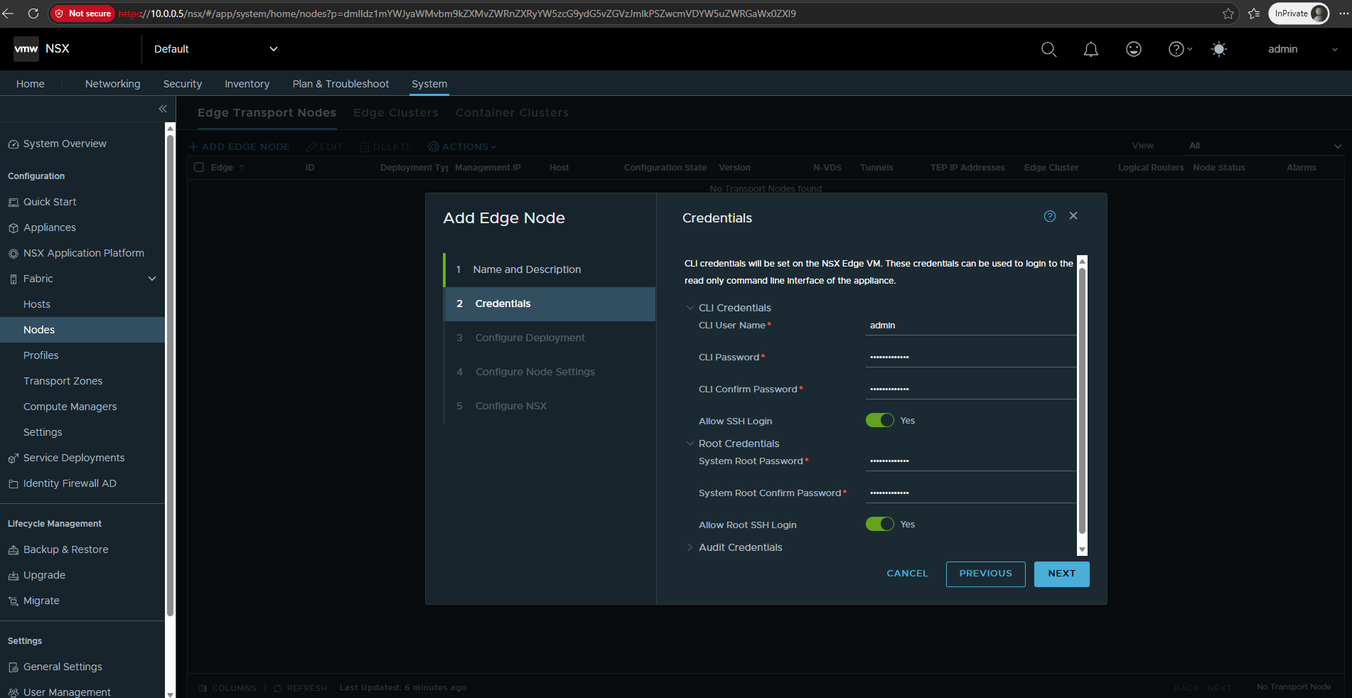
Configure the CLI and root credentials for the NSX Edge appliance.
For my lab, we also enable SSH access for both the
adminandrootaccounts, which will later allow us to inspect and troubleshoot the Edge Node directly from the command line.
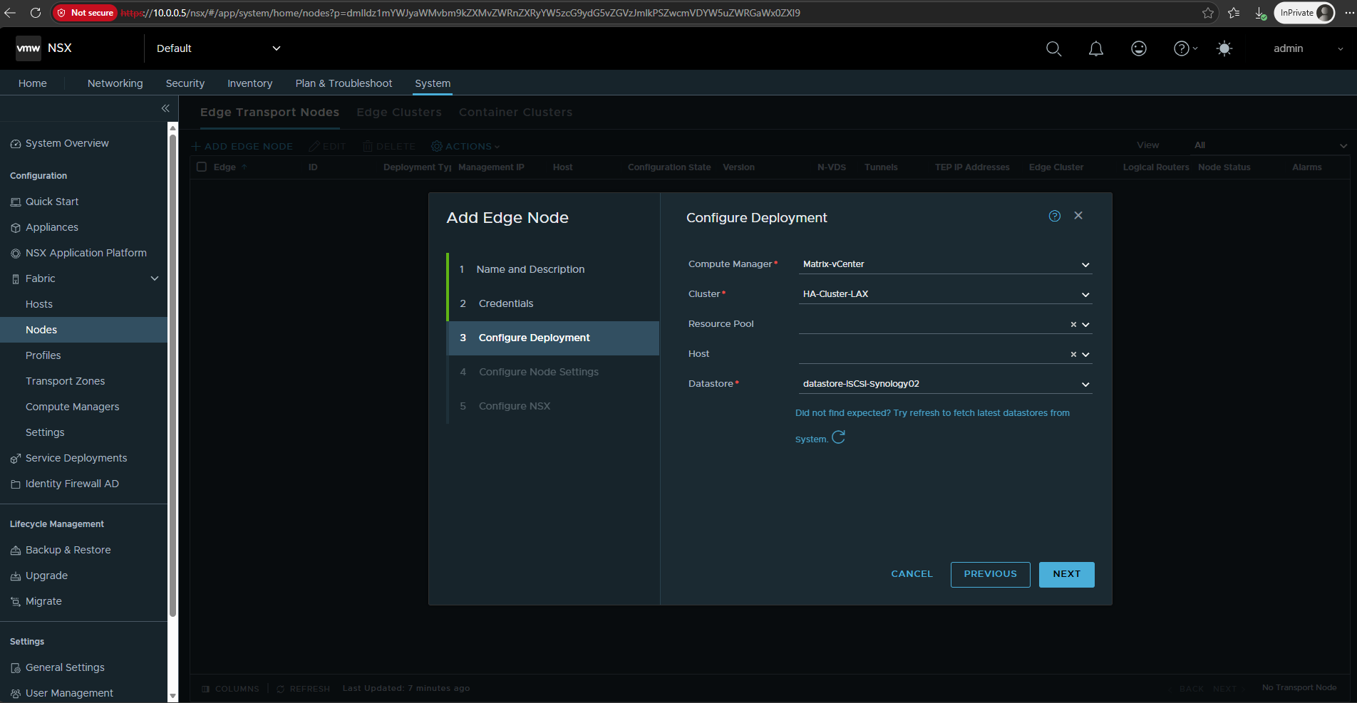
Next, select the vCenter Compute Manager and the vSphere resources on which the NSX Edge appliance will be deployed.
I will deploy
Matrix-NSX-Edge01into my existing HA-Cluster-LAX and use the shared iSCSI datastoredatastore-ISCSI-Synology02. I will leave the Resource Pool and specific ESXi host unselected so that placement is handled at the cluster level.
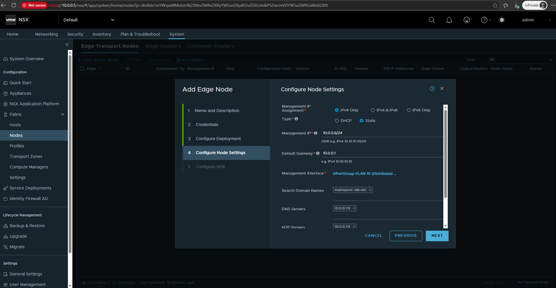
Next, configure the management network settings for the NSX Edge Node. For my lab, I will use a static IPv4 address and connect the management interface to the existing VLAN 10 management network, just like the NSX Manager.
I will use
10.0.0.6/24with10.0.0.1as the default gateway (my VRF-aware Ubuntu router providing upstream/WAN connectivity for the vSphere lab) and configurematrixpost-lab.netas the search domain and10.0.0.70as both the DNS and NTP server (my AD domain controller).
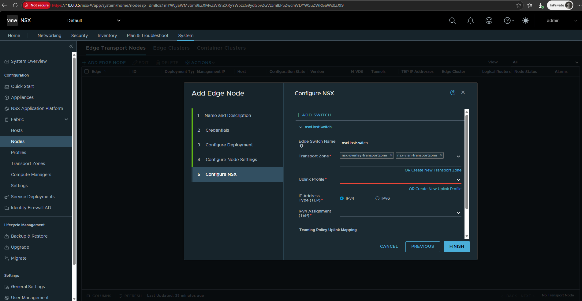
And now we reach the important NSX dataplane configuration for the Edge Node. Here we configure the Edge’s NSX host switch, including its Transport Zones, Uplink Profile, TEP addressing, and physical uplink mappings.
For my lab, I will configure this Edge with both transport zones (
nsx-overlay-transportzone,nsx-vlan-transportzone) because it needs to participate in the overlay and later provide north-south connectivity through a VLAN-backed uplink toward my VRF-aware Ubuntu router.For the Uplink Profile, we don’t choose one of those defaults yet. I will create a dedicated, e.g.
Edge-Uplink-Profile-LAX, so the Edge configuration is explicit and understandable instead of hiding behind one of VMware’s defaults.
So I will click on Create New Uplink Profile below.
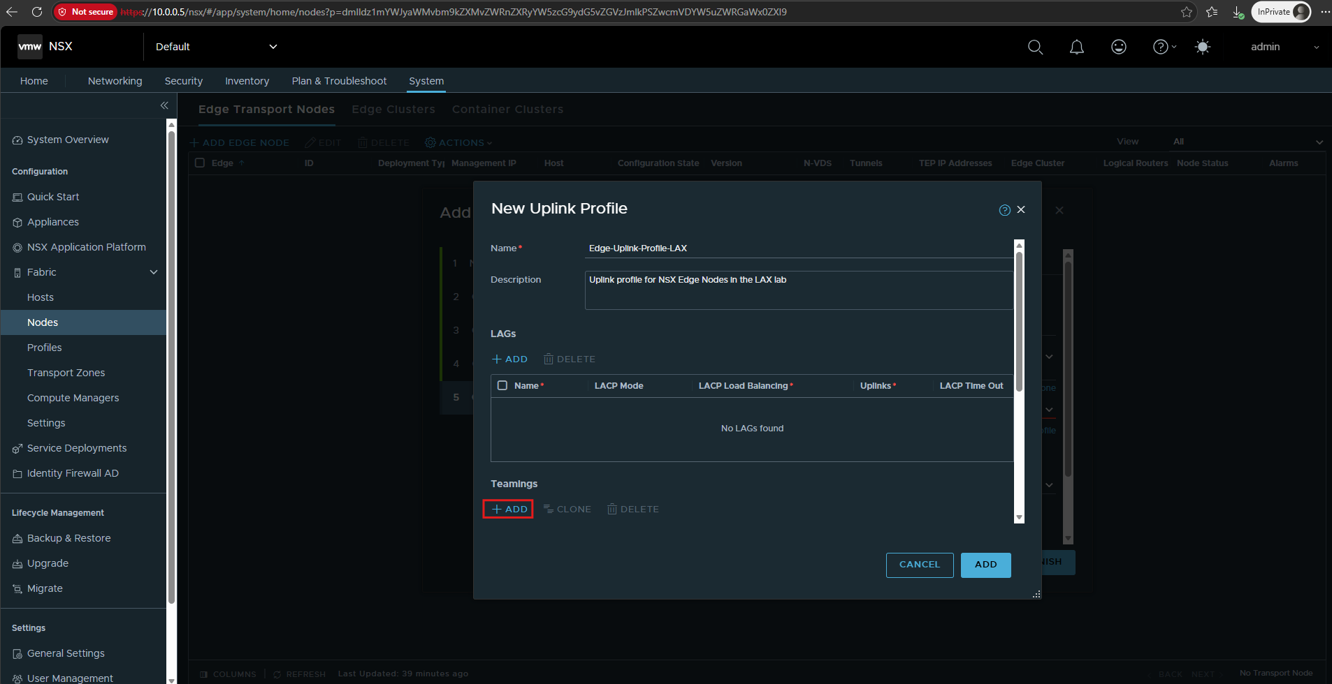
First, we enter a name and description for the new Edge-specific uplink profile. Then click ADD under Teamings and create a new named teaming policy.
That’s where we’ll define our Edge uplink mapping.
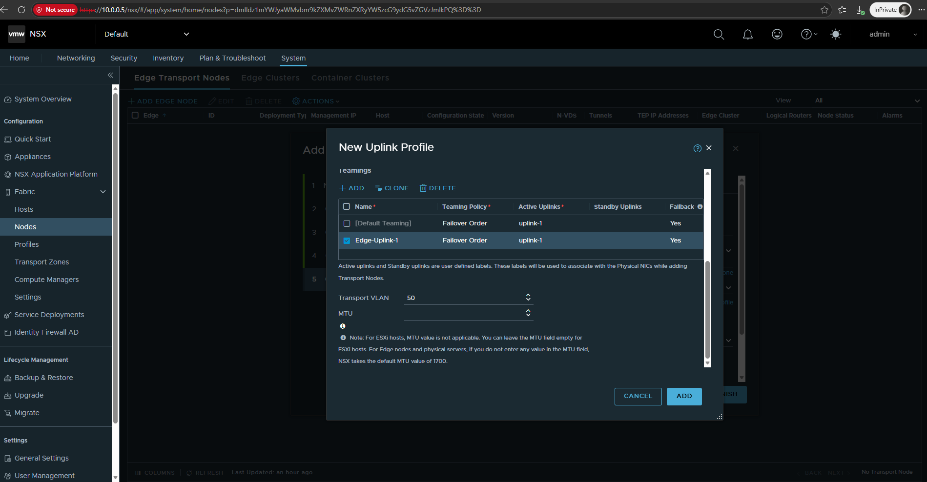
NSX provides a non-editable Default Teaming entry. We therefore add a named teaming policy called Edge-Uplink-1, use Failover Order, and assign uplink-1 as its active uplink.
The Default Teaming policy also requires an active uplink, otherwise NSX reports a validation error. We therefore assign
uplink-1as the active uplink to both the Default Teaming policy and our namedEdge-Uplink-1policy, while leaving the standby uplinks empty.We configure VLAN 50 as the Transport VLAN, matching the transport network already used by our ESXi TEPs. The MTU is left empty; for Edge Nodes, NSX therefore uses its default MTU of 1700 bytes, which is sufficient for the additional GENEVE encapsulation overhead in my lab.
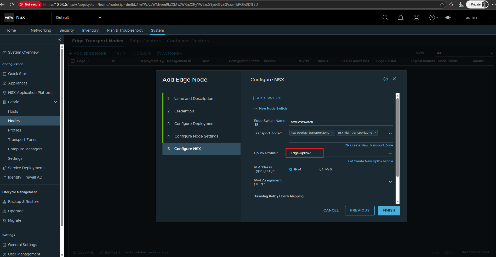
After clicking Add, NSX creates the new uplink profile and automatically selects
Edge-Uplink-1in the Configure NSX step. The Edge Node is now associated with our overlay and VLAN transport zones and the newly created Edge-specific uplink configuration.
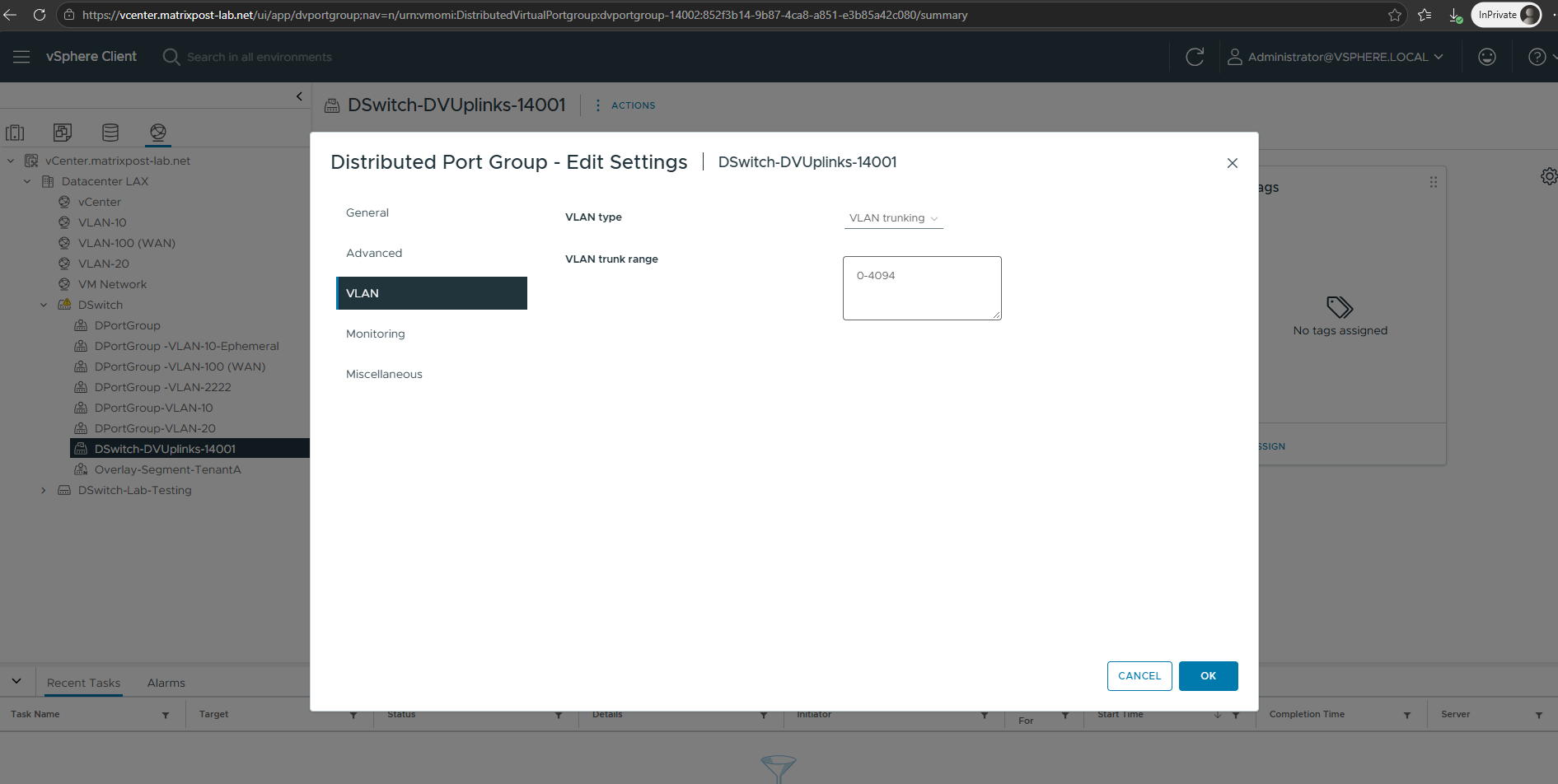
The underlying vSphere Distributed Switch uplinks must allow all VLANs required by the NSX Edge, including the TEP transport VLAN and the VLANs used later for Tier-0 external connectivity.
In my lab, the distributed uplink port group still uses the default VLAN trunk range
0-4094, so all VLANs are already permitted and no additional configuration is required.
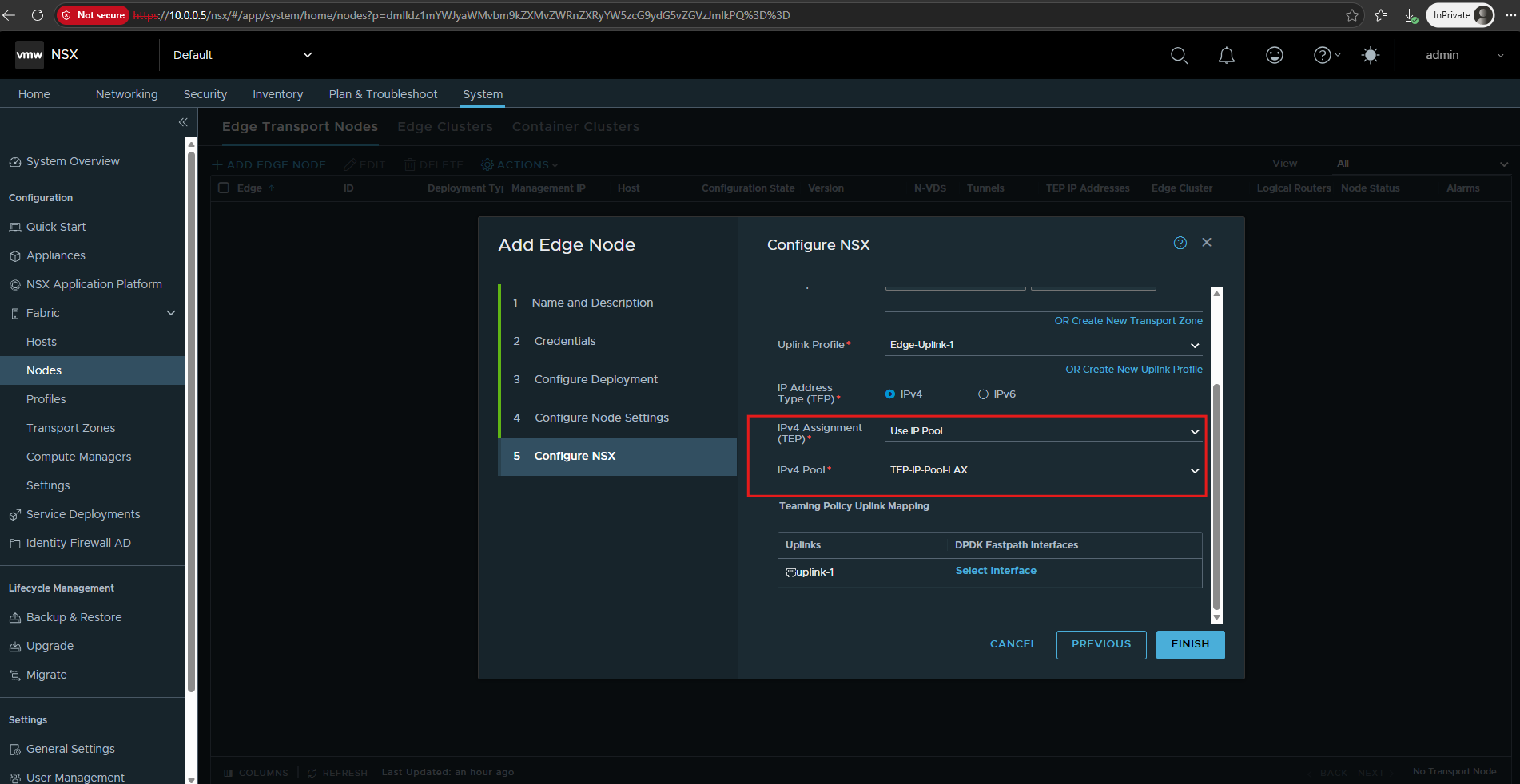
Next, we configure the TEP (Tunnel Endpoint) for the NSX Edge Node.
We use IPv4 and assign the Edge TEP address from our existing
TEP-IP-Pool-LAX, placing the Edge in the same VLAN 50 transport network used by the ESXi TEPs.
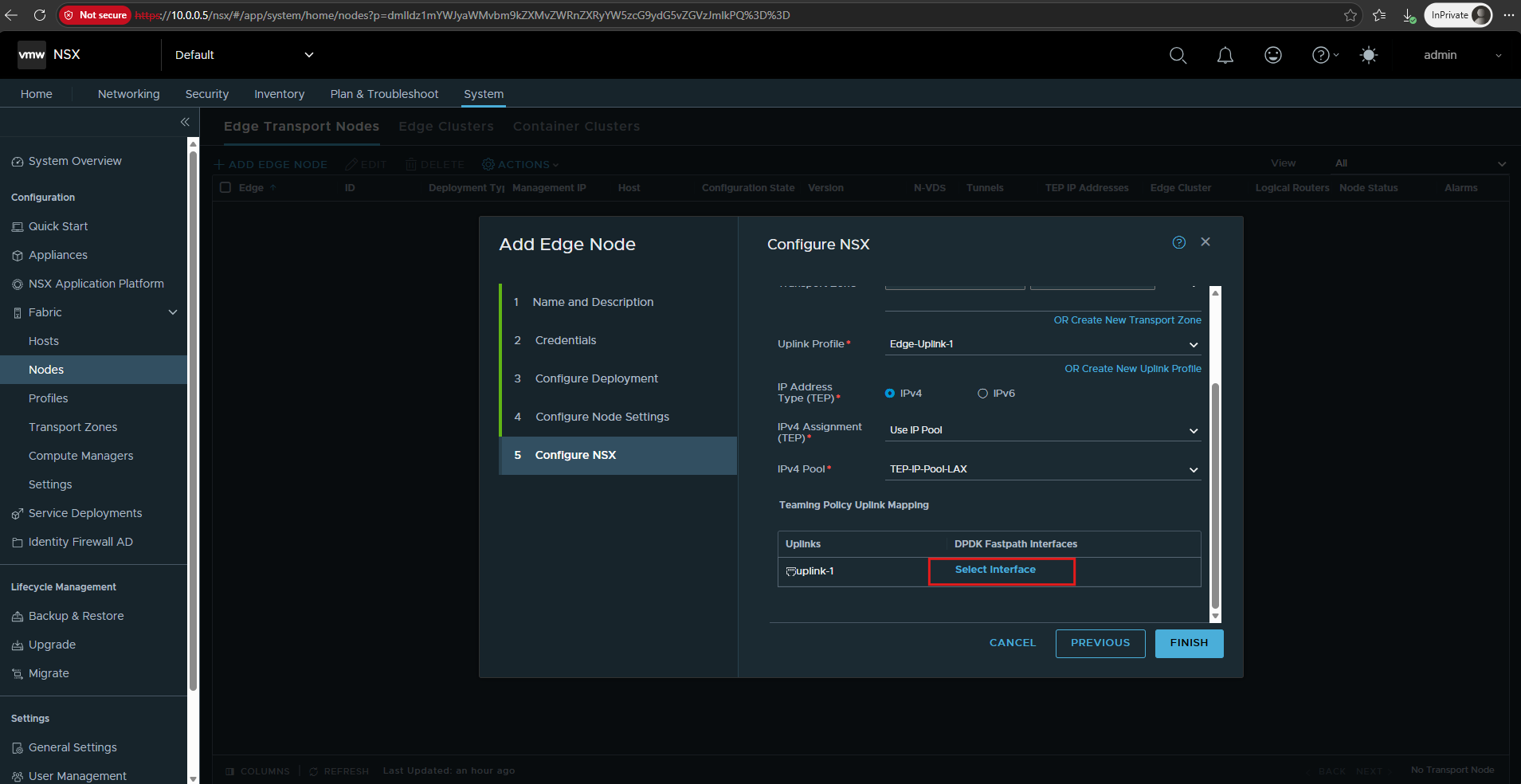
Next, we need to map uplink-1 to a DPDK Fastpath Interface, which connects the Edge datapath to the underlying vSphere network.
DPDK (Data Plane Development Kit) Fastpath Interfaces are the high-performance dataplane interfaces used by the NSX Edge for processing network traffic. In our virtual Edge deployment,
uplink-1is mapped to such a fastpath interface, which provides the Edge connectivity to the NSX transport network.The Edge appliance has a management NIC for management-plane access (
10.0.0.6) and one or more DPDK Fastpath NICs for the actual NSX dataplane. That dataplane carries the Edge TEP/GENEVE traffic and, through logical interfaces realized by NSX, the north-south traffic toward the upstream network.
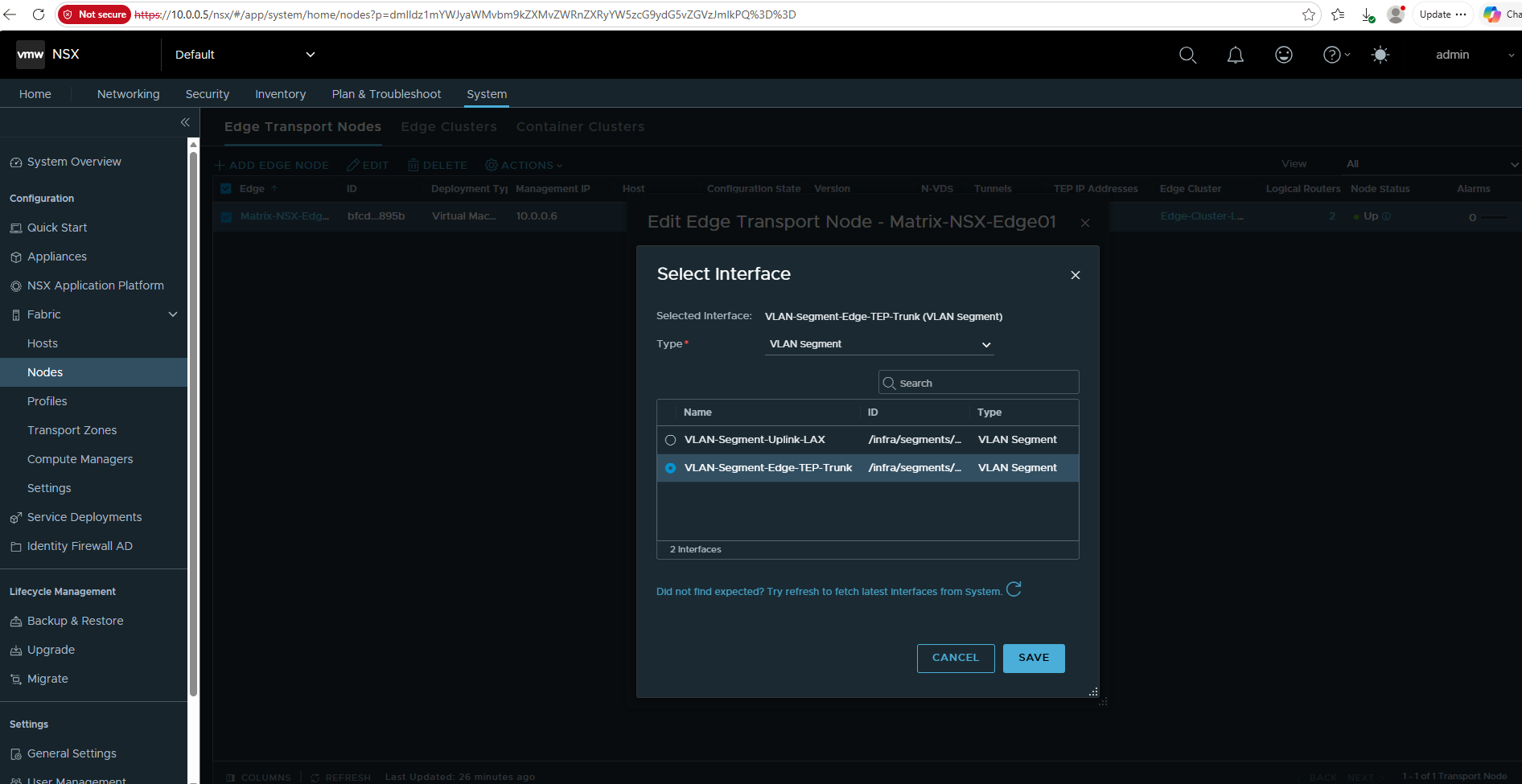
For this, we will use an NSX VLAN-backed segment instead of a regular vSphere Distributed Port Group. Because the Edge datapath interface is attached to the same NSX-prepared VDS used by our ESXi transport nodes, using an NSX-managed VLAN segment ensures that the Edge TEP participates correctly in the NSX transport network and can establish its GENEVE tunnels with the ESXi TEPs.
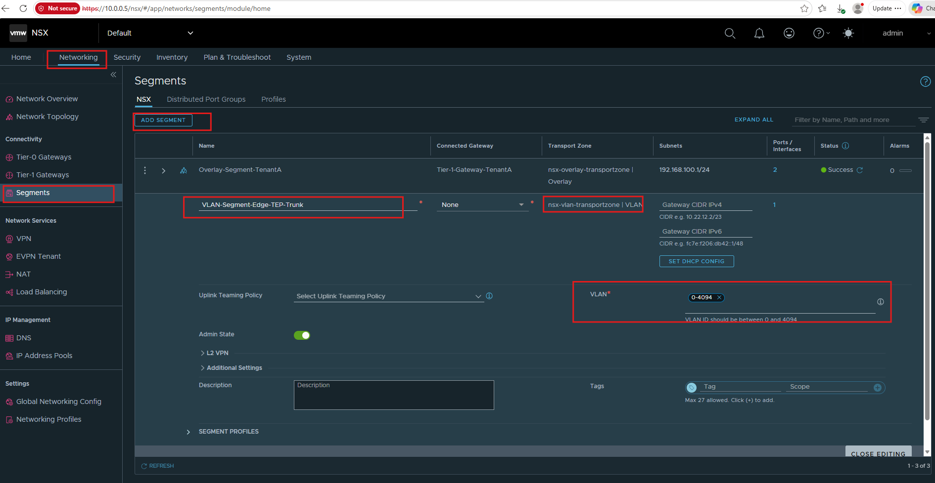
I will create the segment VLAN-Segment-Edge-TEP-Trunk in the nsx-vlan-transportzone and configure it as a VLAN trunk.
Under Networking → Segments, click Add Segment and configure
VLAN-Segment-Edge-TEP-Trunkin thensx-vlan-transportzone.Because the Edge uplink must carry the required transport VLAN, configure the segment as a VLAN trunk (
0-4094). No gateway or subnet is required for this segment.
Next, we map uplink-1 to the DPDK Fastpath Interface used by the NSX Edge dataplane. Click Select Interface to select the NSX-managed VLAN segment that will provide the Edge TEP connectivity.
For the DPDK Fastpath Interface, we select the previously created VLAN-Segment-Edge-TEP-Trunk. This NSX-managed VLAN segment provides the underlying connectivity for the Edge TEP while allowing the configured transport VLAN 50 to be carried between the Edge and the ESXi transport nodes.
With the TEP IP pool and DPDK Fastpath interface configured, the Edge transport configuration is complete. We can now click Finish to deploy and configure the new NSX Edge Node.
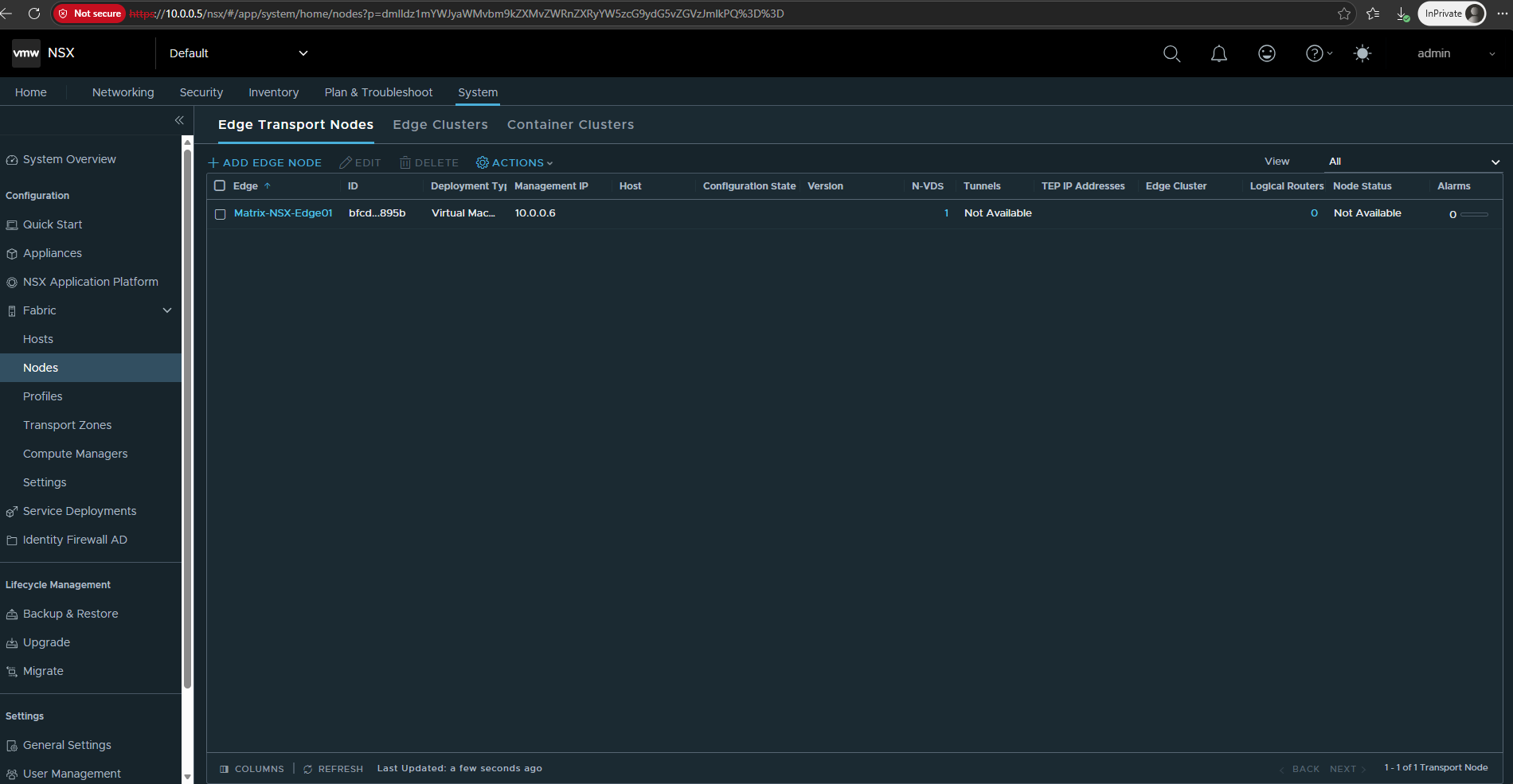
After clicking Finish, the new Edge appliance appears under Edge Transport Nodes as Matrix-NSX-Edge01 with its management IP 10.0.0.6.
The TEP IP address and Node Status initially show Not Available while the appliance is being deployed and initialized, so we wait for the configuration to complete.
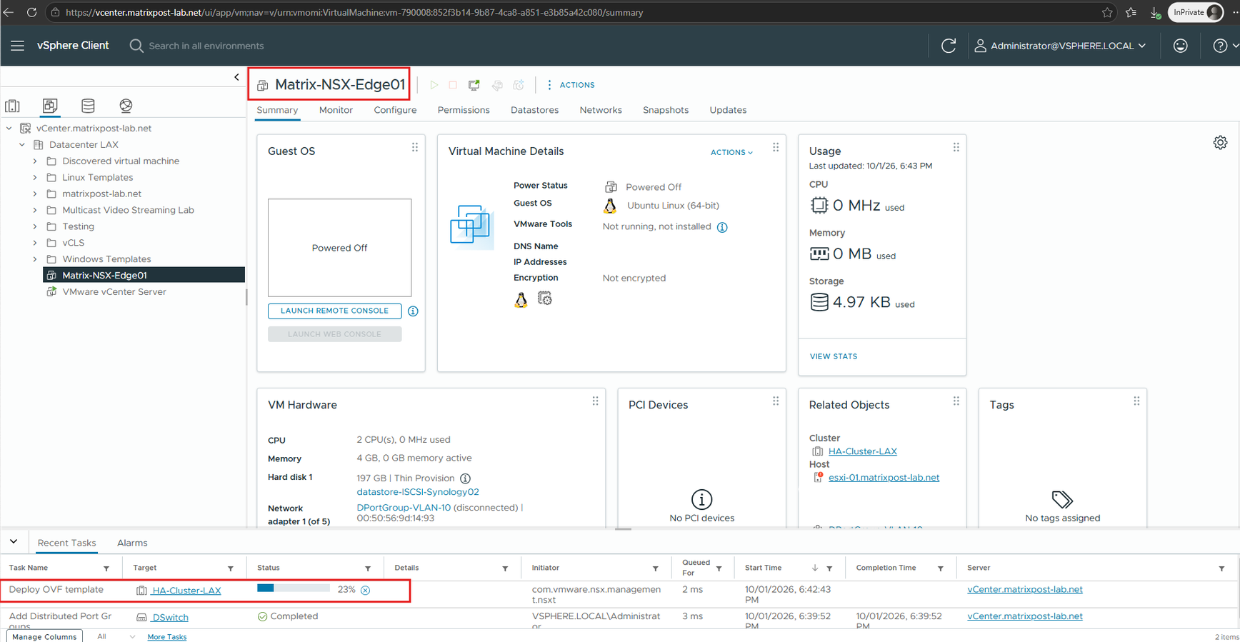
NSX Manager now automatically starts the OVF deployment of Matrix-NSX-Edge01 through the registered vCenter.
The Edge appliance is created as a new VM in HA-Cluster-LAX and will be powered on and configured automatically once the deployment has completed.
The NSX Edge appliance is now powered on and has successfully received its configured management address 10.0.0.6.
In vCenter, we can also verify that the Edge VM is connected to both the regular management network and our newly created NSX VLAN-backed segment
VLAN-Segment-Edge-TEP-Trunk, which provides the Edge dataplane connectivity.
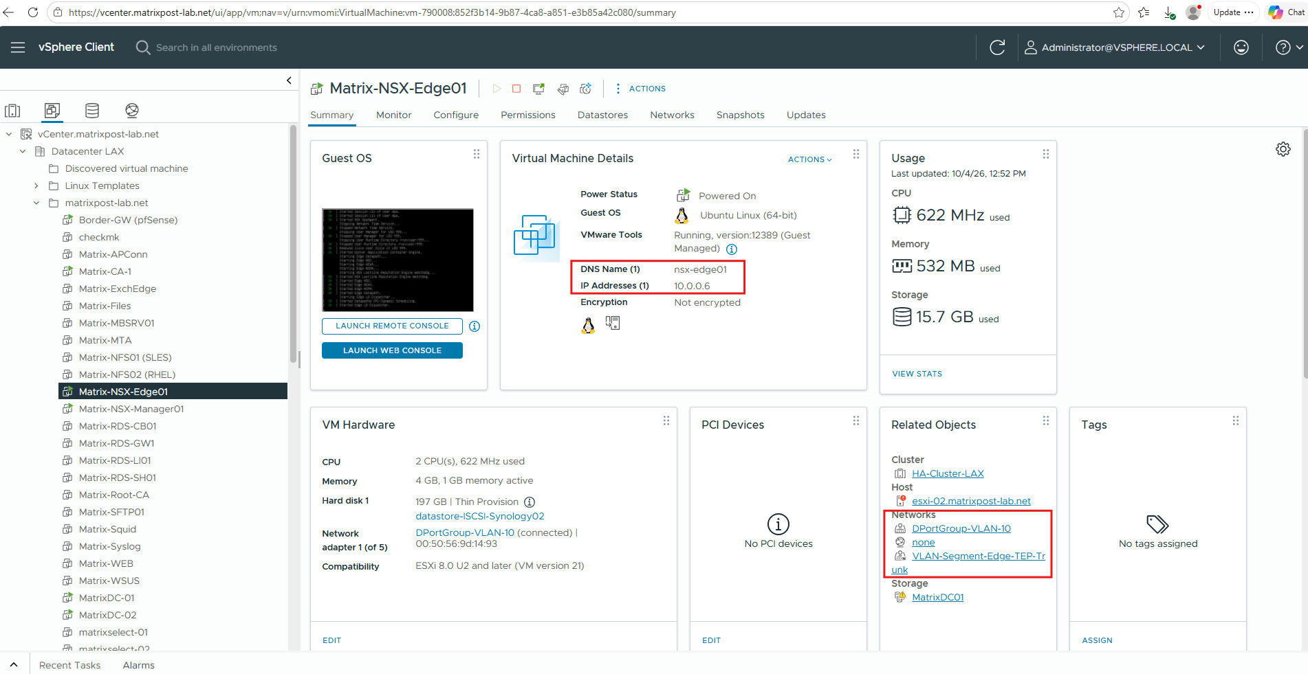
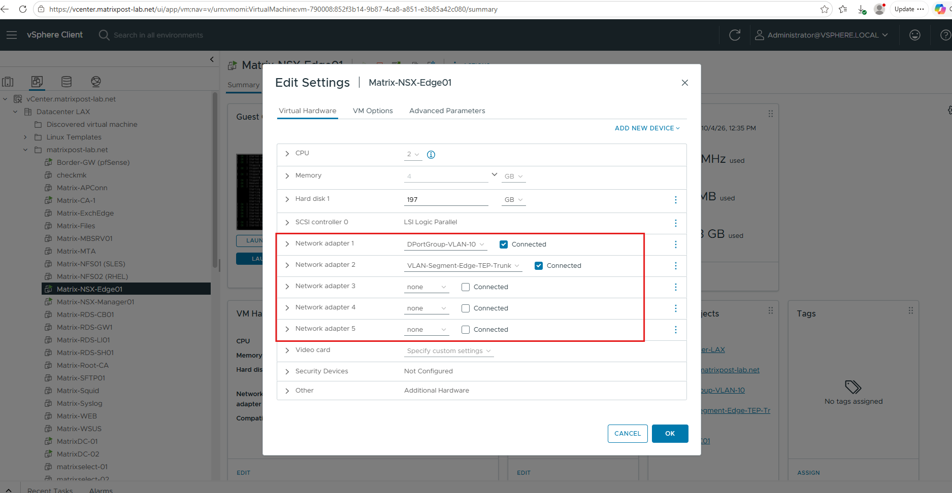
Looking at the NSX Edge VM hardware in the vSphere Client makes this separation easier to see. Network adapter 1 is connected to DPortGroup-VLAN-10 and provides the management connectivity for the Edge Node (10.0.0.6).
Network adapter 2 is connected to VLAN-Segment-Edge-TEP-Trunk and represents the dataplane/Fastpath interface used by NSX. The remaining virtual network adapters were created automatically as part of the NSX Edge appliance deployment and are currently unused, but can be used for additional dataplane connectivity if required.
Although both interfaces are ordinary virtual NICs from the vSphere perspective, NSX assigns them completely different roles: one belongs to the management plane, while the other is used by the NSX Edge dataplane for TEP/GENEVE and routed network traffic.
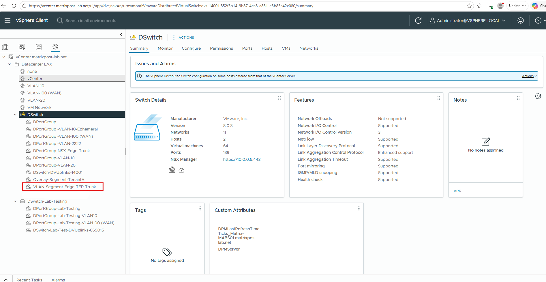
The newly created NSX VLAN-backed segment
VLAN-Segment-Edge-TEP-Trunkis also visible under our existingDSwitchin the vSphere Client; networks created and managed by NSX are marked with the smallNicon, distinguishing them from regular vSphere Distributed Port Groups.
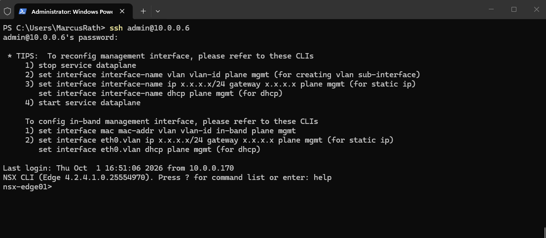
Finally, we can verify direct access to the Edge appliance by connecting via SSH to its management IP 10.0.0.6.
After logging in with the
adminaccount, the NSX CLI confirms that we are connected to our new Edge Node running NSX Edge 4.2.4.1.
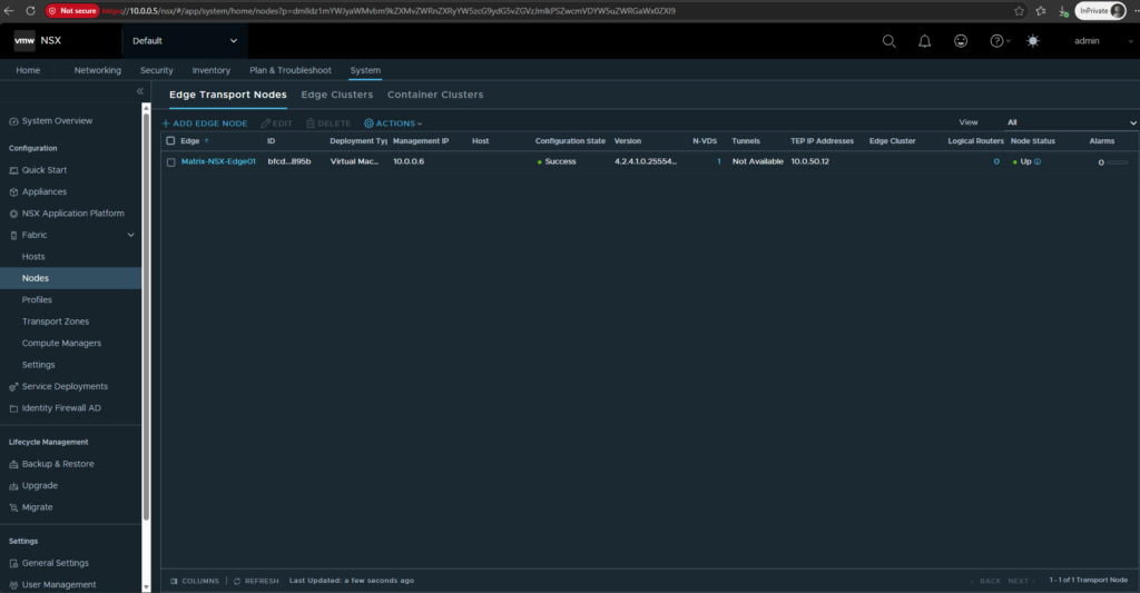
After the deployment and initialization have completed, the new Matrix-NSX-Edge01 Edge Transport Node reports Configuration State: Success and Node Status: Up.
The Edge Node uses
10.0.0.6for management and has received the TEP address10.0.50.12from ourTEP-IP-Pool-LAX, confirming that it is ready to participate in the NSX overlay network.
Create the NSX Edge Cluster
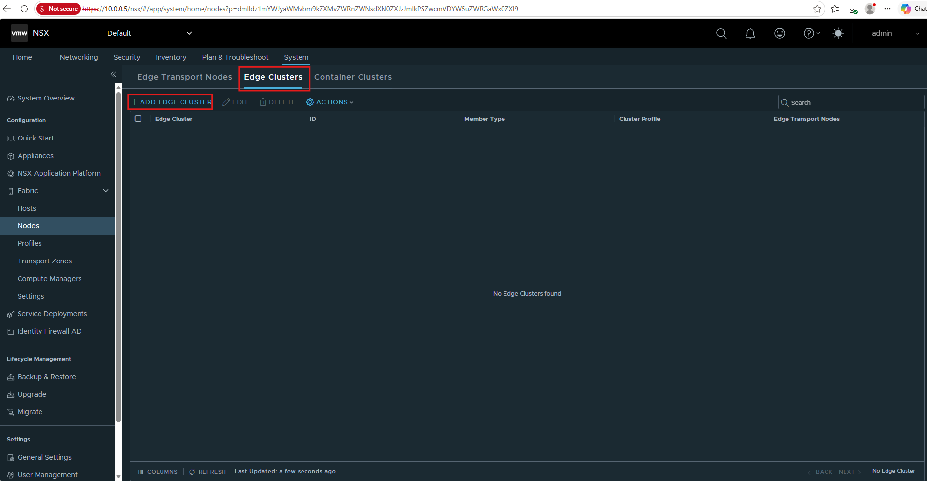
Next, we create an Edge Cluster and add our Matrix-NSX-Edge01 Edge Transport Node as a member.
The Edge Cluster provides the Edge resources on which centralized NSX routing and network services can run; while production environments typically use multiple Edge Nodes for redundancy, a single Edge Node is sufficient for my lab.
Go to: System → Fabric → Nodes → Edge Clusters
Then click Add Edge Cluster.
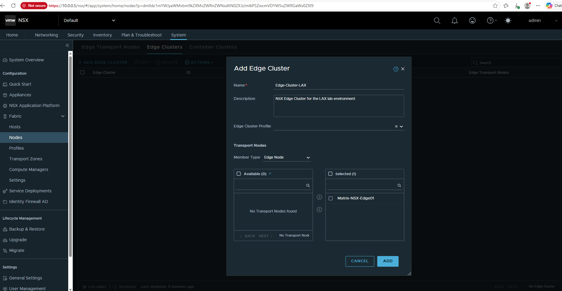
- Name:
Edge-Cluster-LAX - Description:
NSX Edge Cluster for the LAX lab environment - Edge Cluster Profile: leave the default selected
- Member Type:
Edge Node - Select Matrix-NSX-Edge01 → click the > arrow so it moves to Selected
Then click ADD.
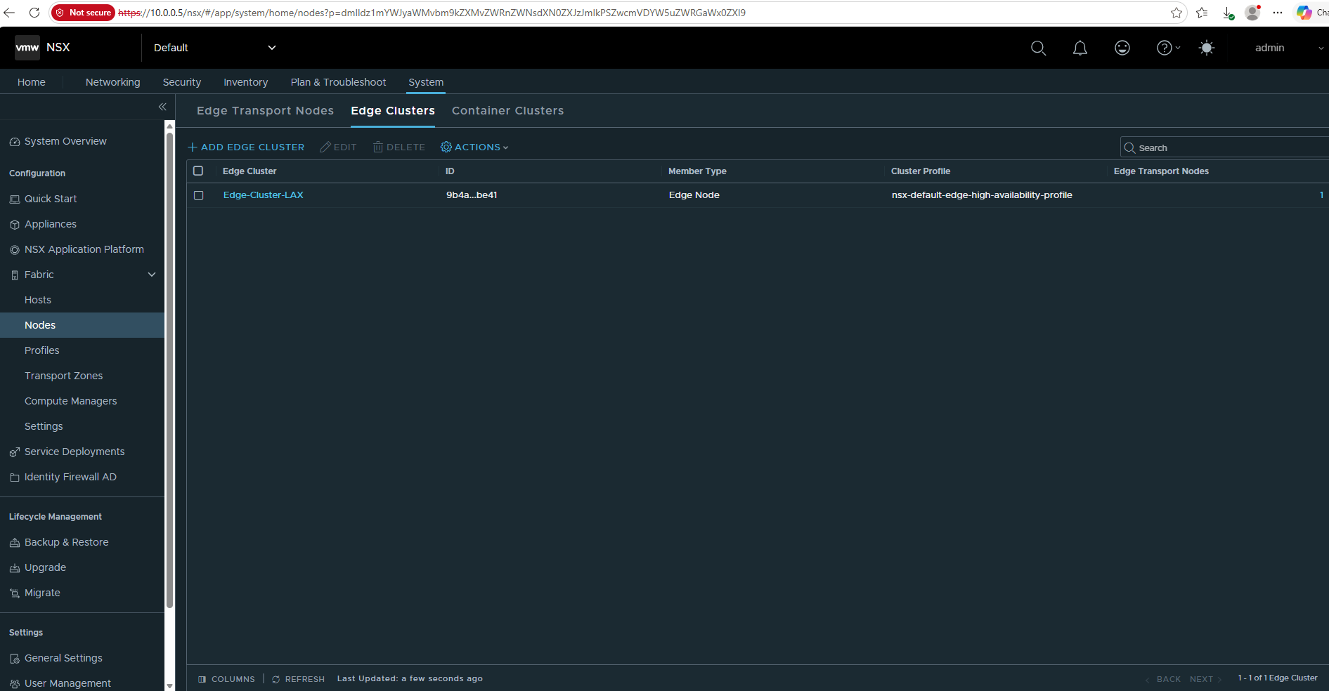
The Edge-Cluster-LAX is created, using the default nsx-default-edge-high-availability-profile, with 1 Edge Transport Node.
Create the Tier-0 Gateway
Next, we create a Tier-0 Gateway, which provides the north-south routing layer between the NSX environment and the external physical network.
The Tier-0 Gateway will run on our Edge-Cluster-LAX and later provide connectivity toward our VRF-aware Ubuntu router at 10.0.0.1 and the external network.
Go to: Edge Node → Edge Cluster → Tier-0 Gateway
Click on ADD Gateway → Tier-0.
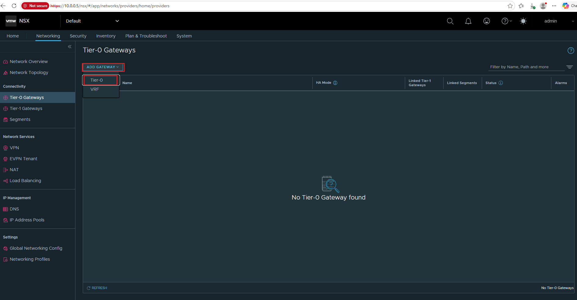
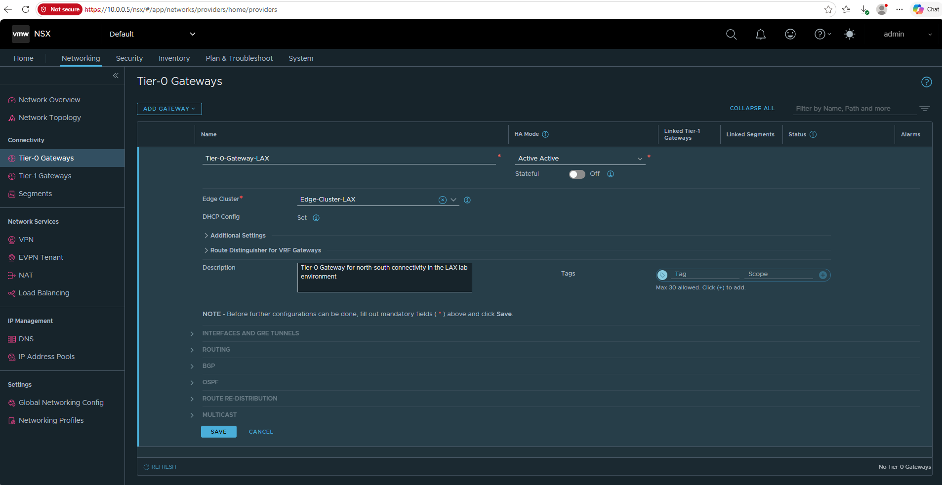
- Name:
Tier-0-Gateway-LAX - HA Mode:
Active Active— leave the default - Stateful:
Off - Edge Cluster:
Edge-Cluster-LAX - DHCP Config: leave unset
- Route Distinguisher for VRF Gateways: leave unset for now; we will revisit this setting later when introducing VRF Gateways and explain why it is not required for our VRF-Lite design.
- Description:
Tier-0 Gateway for north-south connectivity in the LAX lab environment - Tags: none
Then click SAVE.
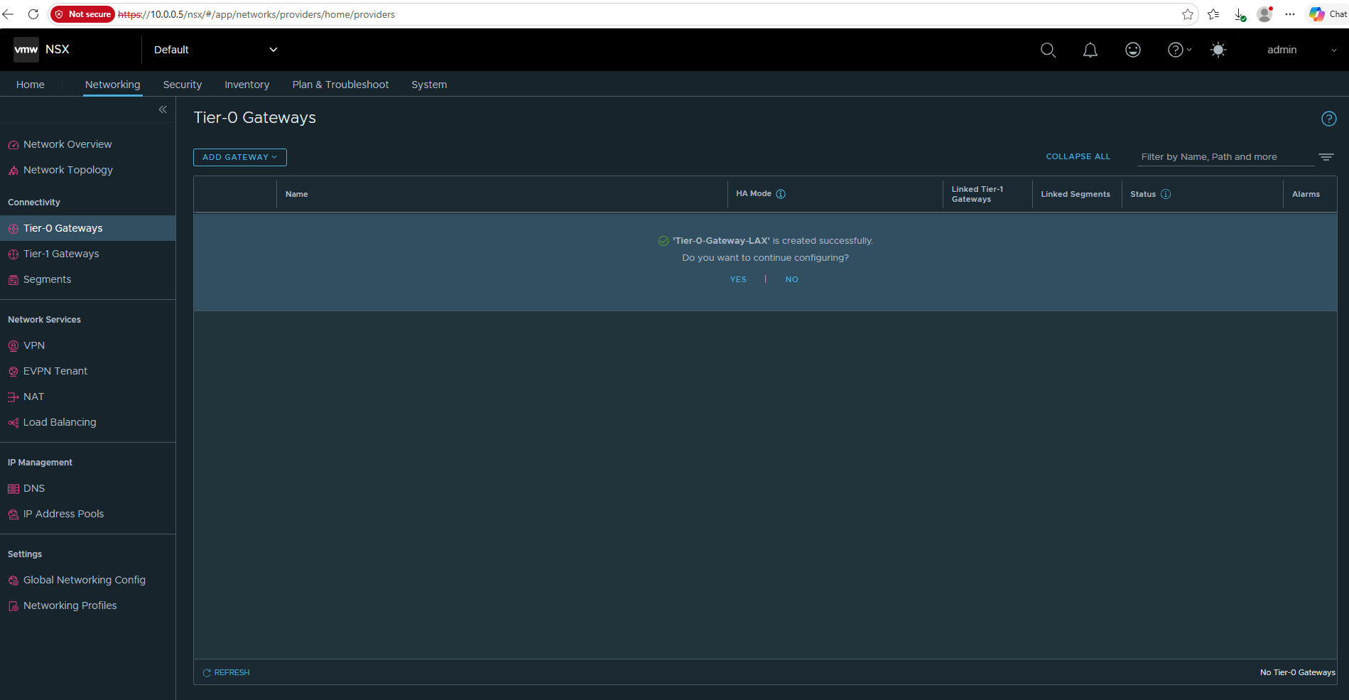
Click No.
The Tier-0 Gateway has now been created successfully. In our multi-tenant design,
Tier-0-Gateway-LAXacts as the parent Tier-0 for the individual tenant VRF Gateways rather than providing the tenant upstream connection directly.Each tenant VRF Gateway will later receive its own isolated external handoff toward the VRF-aware Ubuntu router.
Before creating the tenant VRF Gateways, the parent Tier-0 requires an external interface providing the underlying provider uplink and Edge path for its child VRFs.
We therefore first create a VLAN-backed segment on VLAN 10, which will be used by the external interface of Tier-0-Gateway-LAX.
Next go to Networking → Segments → Add Segment.
We’re going to create the VLAN-backed external segment:
Name: VLAN-Segment-Uplink-LAX
Connected Gateway: None
Transport Zone: nsx-vlan-transportzone
Subnets: leave empty
Admin State: On
VLAN: 10
everything else: defaults / empty
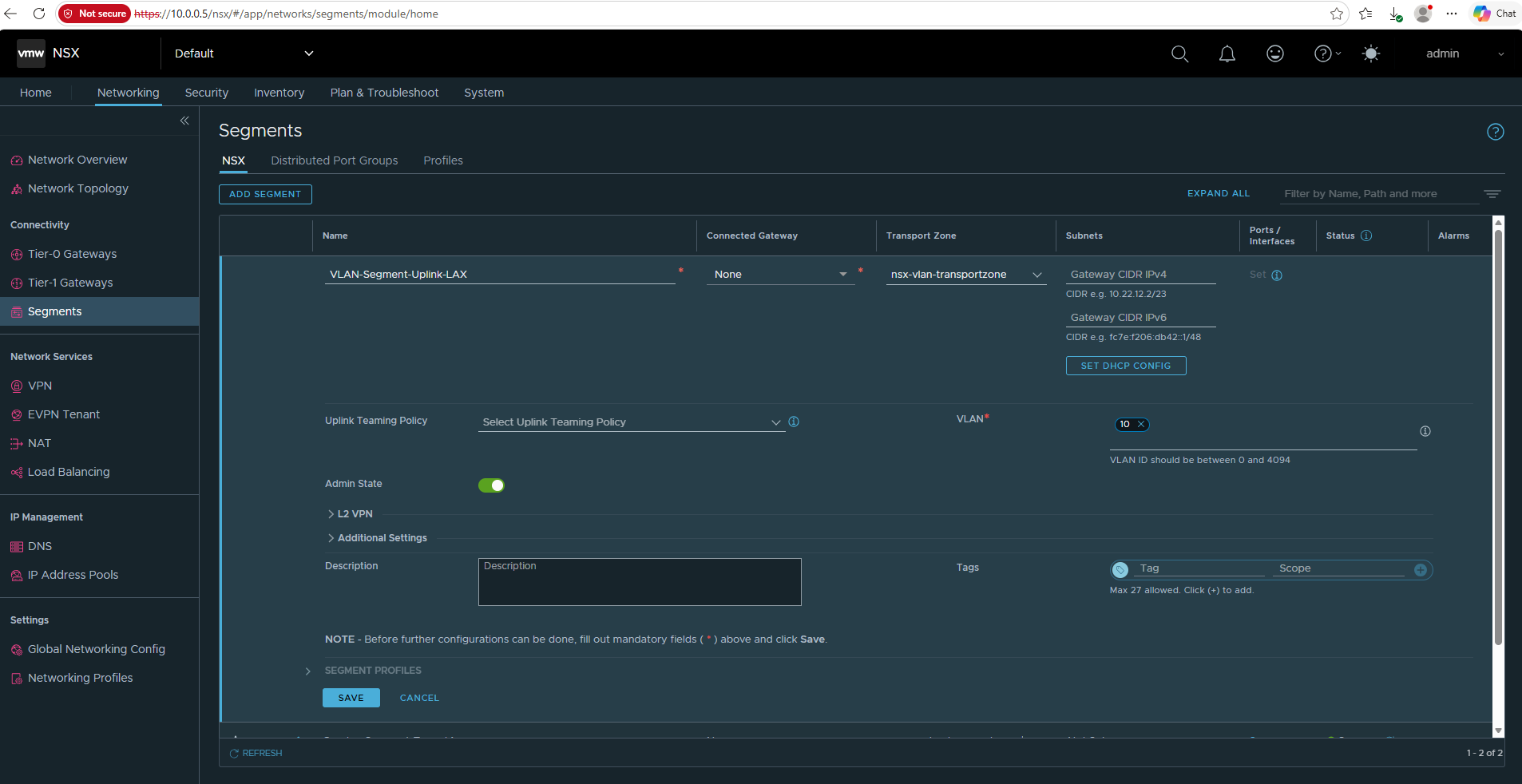
Then Save. This creates the VLAN-backed L2 segment that we’ll select for the Tier-0 external interface.
Click NO; we don’t need further configuration on this segment.
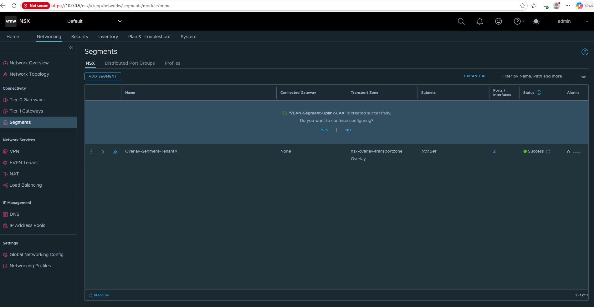
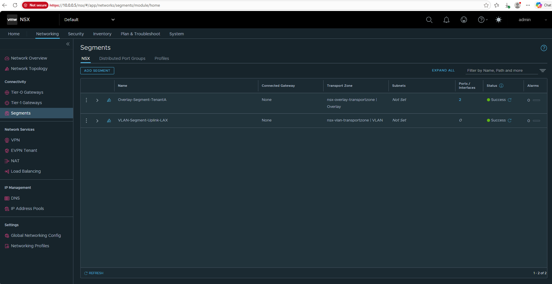
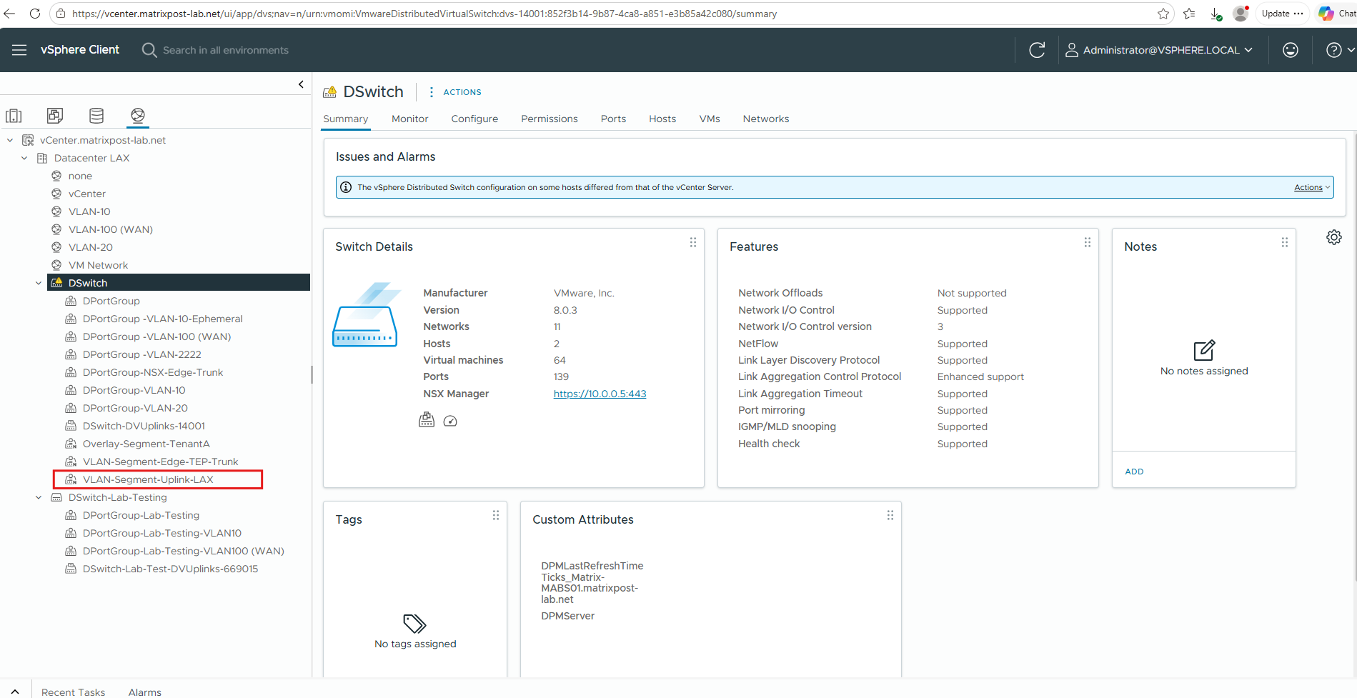
After creating the segment, VLAN-Segment-Uplink-LAX is also visible on our existing vSphere Distributed Switch DSwitch.
The small N icon identifies it as an NSX-managed network, distinguishing it from the regular vSphere Distributed Port Groups; this segment provides the VLAN 10 provider connectivity for the parent Tier-0 external interface (
10.0.0.7).
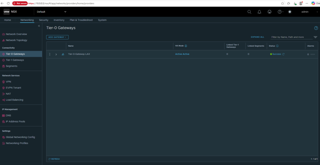
Return to Networking → Tier-0 Gateways, expand Tier-0-Gateway-LAX, and click Edit to continue its configuration and add the parent Tier-0 external uplink interface.
Now that the required VLAN-Segment-Uplink-LAX has been created, we can continue configuring the parent Tier-0 uplink interface. Under Interfaces and GRE Tunnels, click Set next to External and Service Interfaces.
That’s where we’ll create the external interface on the parent Tier-0. This interface resides on the VLAN 10 VLAN-backed network and provides the provider uplink and Edge path required by the child Tier-0 VRF Gateways. Its IP address
10.0.0.7is separate from both the Edge management IP10.0.0.6and the Edge TEP10.0.50.12.
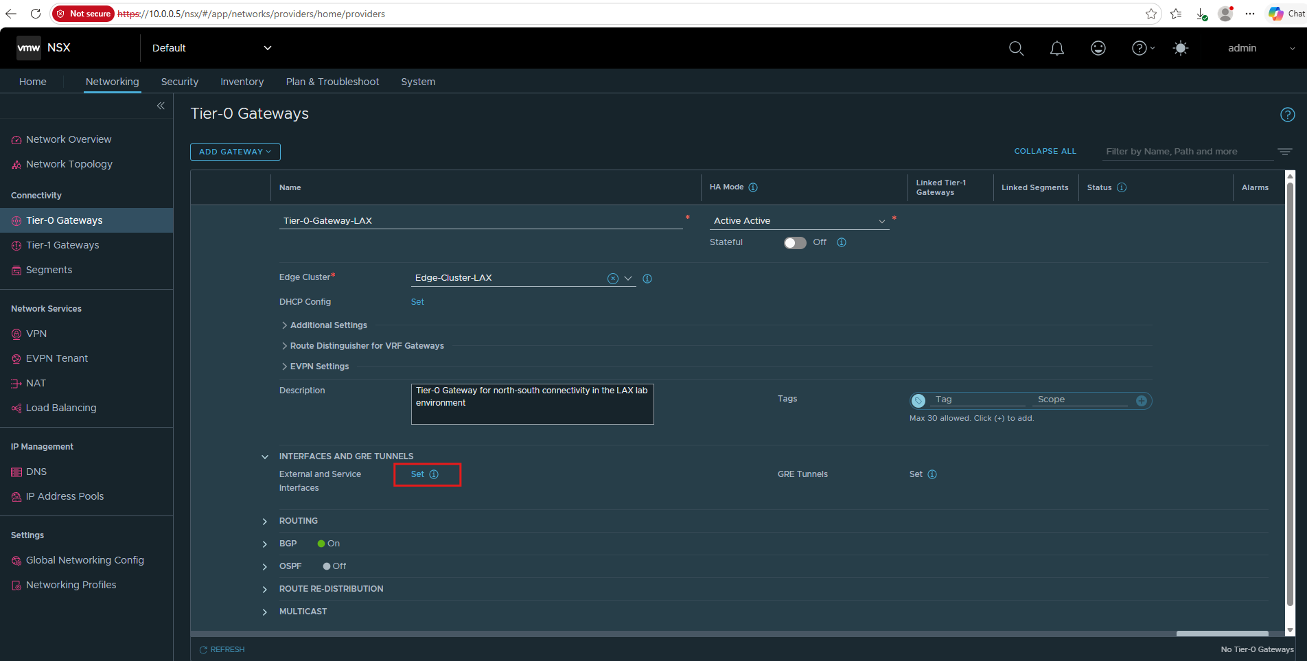
Click ADD INTERFACE.
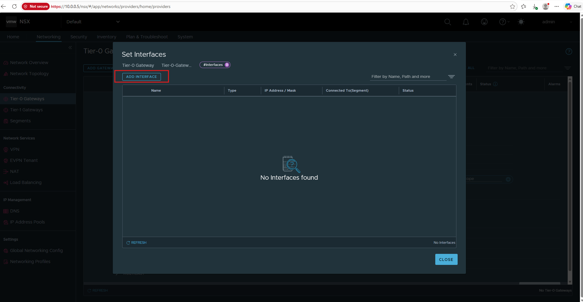
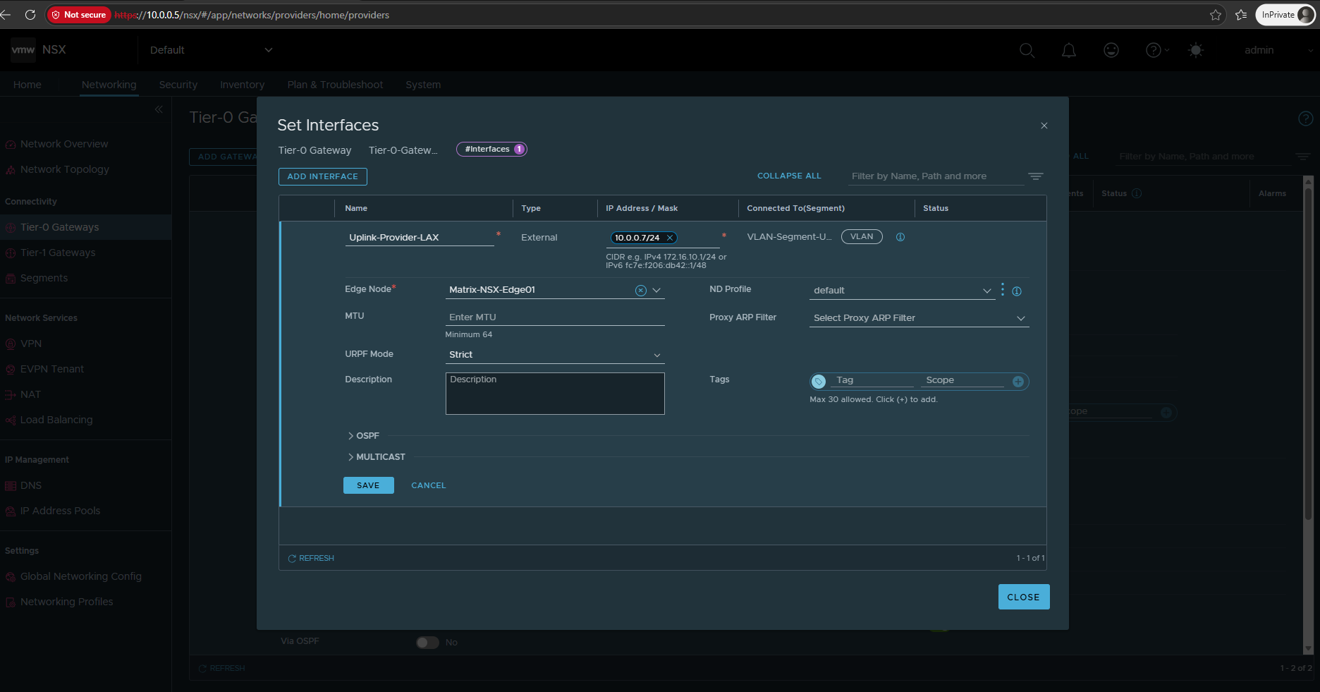
For my lab I will use:
Name: Uplink-Provider-LAX
Type: External
IP Address / Mask: we need to choose a free address from VLAN 10 (10.0.0.0/24) I will use 10.0.0.7/24
Connected To (Segment): VLAN-Segment-Uplink-LAX
Edge Node: Matrix-NSX-Edge01
Click on SAVE.
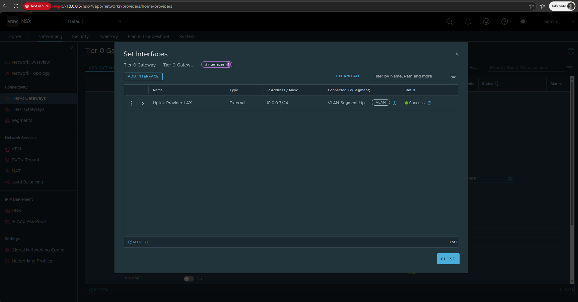
So the parent Tier-0 external interface Uplink-Provider-LAX (10.0.0.7/24) is successfully realized on the Edge and connected to the VLAN uplink segment.
This interface provides the provider uplink and Edge path required by the child Tier-0 VRF Gateways. The actual tenant-specific upstream routing will be configured later through the dedicated external interfaces of the individual Tier-0 VRF Gateways.
Configure VRF-Aware Upstream Routing
Now that routing within the NSX environment is working, we can extend connectivity toward the upstream network.
Because our design will later include multiple isolated tenants with potentially overlapping IP address spaces, the upstream router must preserve these separate routing domains as well. For this lab, we will therefore replace pfSense with a VRF-aware Ubuntu router at 10.0.0.1, similar to the Linux VRF design used in my Microsoft HNV series.
Deploy the VRF-Aware Ubuntu Router
The Ubuntu router will use two network interfaces: one dedicated to management connectivity and one for the upstream NSX routing path.
The upstream interface is connected to the DPortGroup-NSX-VRF-Trunk, with VLAN subinterfaces created on Ubuntu and assigned to the individual Linux VRFs to keep the tenant routing domains isolated.
For the second network adapter of our Ubuntu router, we create a dedicated Distributed Port Group DPortGroup-NSX-VRF-Trunk on the existing DSwitch.
We configure it for VLAN trunking (
0-4094), allowing multiple tenant/VRF VLANs to be carried over a single virtual NIC.
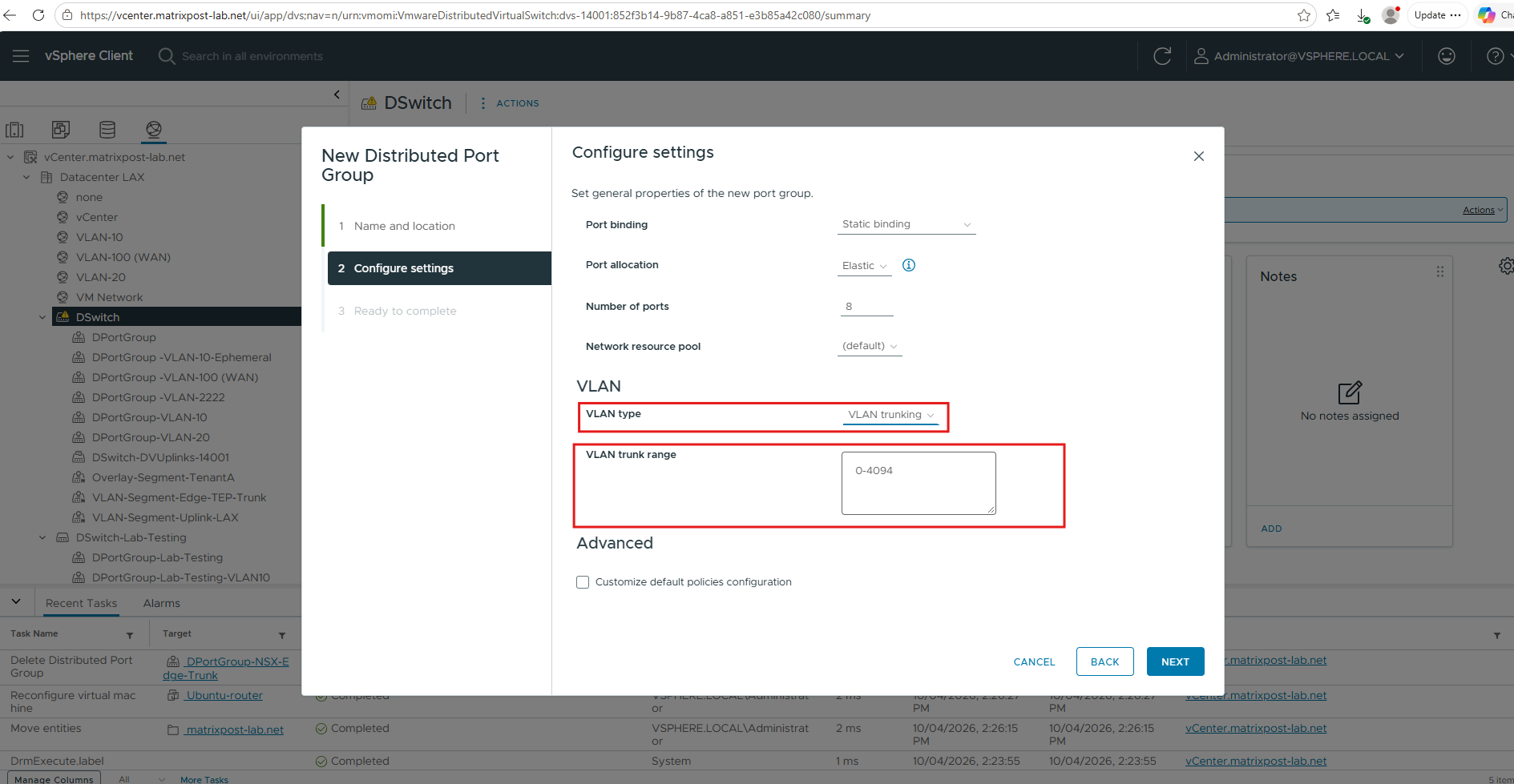
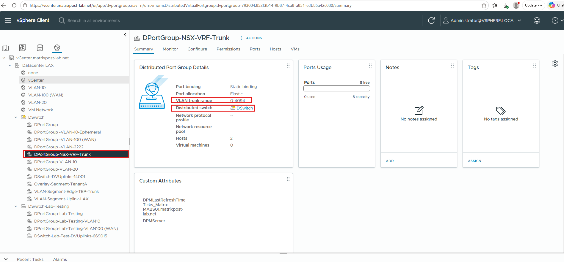
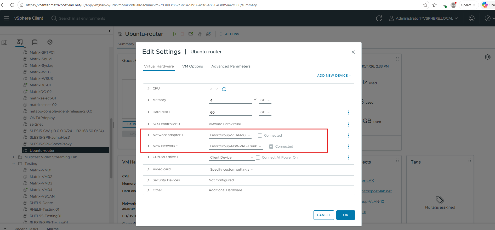
The Ubuntu router now is equipped with two network adapters: the first connects to DPortGroup-VLAN-10 for management connectivity, while the second connects to our new DPortGroup-NSX-VRF-Trunk.
On the second interface, we will later create VLAN subinterfaces for the individual tenant routing domains and assign them to separate Linux VRFs.
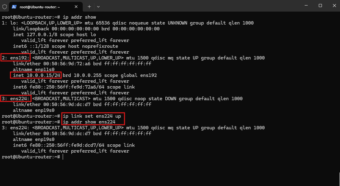
The Ubuntu router uses ens192 as its management interface with 10.0.0.15/24, while ens224 is connected to our VRF trunk and intentionally has no IPv4 address.
We bring
ens224up as the parent trunk interface; the actual tenant addressing will later be configured on VLAN subinterfaces assigned to the individual Linux VRFs.
Enable IPv4 Forwarding
Because the Ubuntu VM acts as a router between the individual tenant VRFs and the upstream network, IPv4 forwarding must be enabled at the Linux kernel level.
sudo nano /etc/sysctl.d/99-ip-forward.conf
Add:
net.ipv4.ip_forward=1
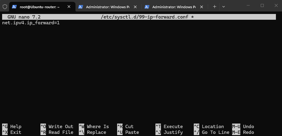
Apply it:
sudo sysctl --system
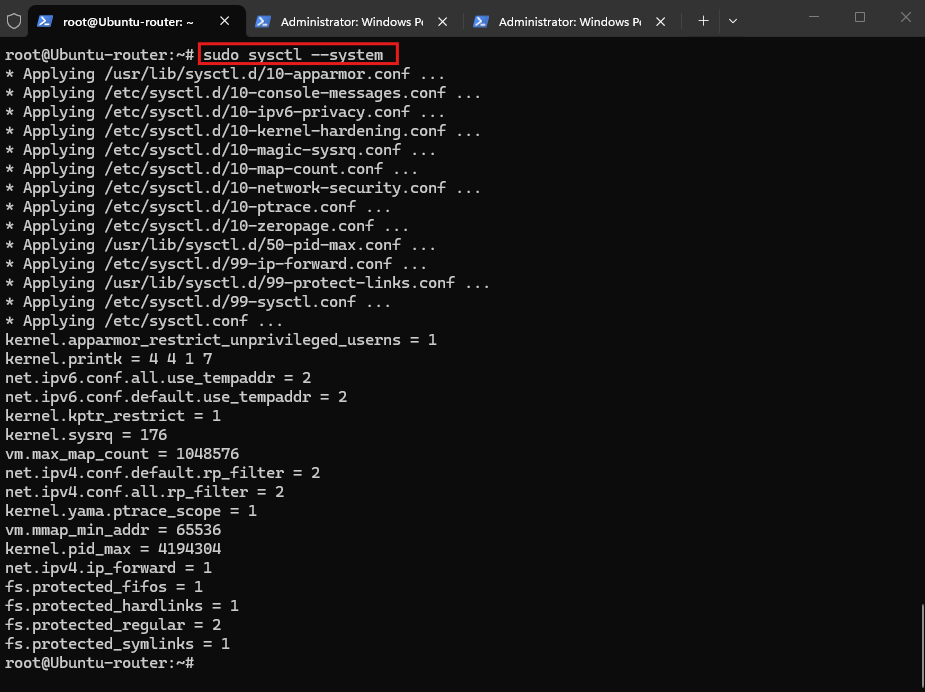
Verify:
sysctl net.ipv4.ip_forward
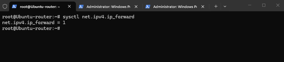
Prepare the Parent Tier-0 for VRF Gateways
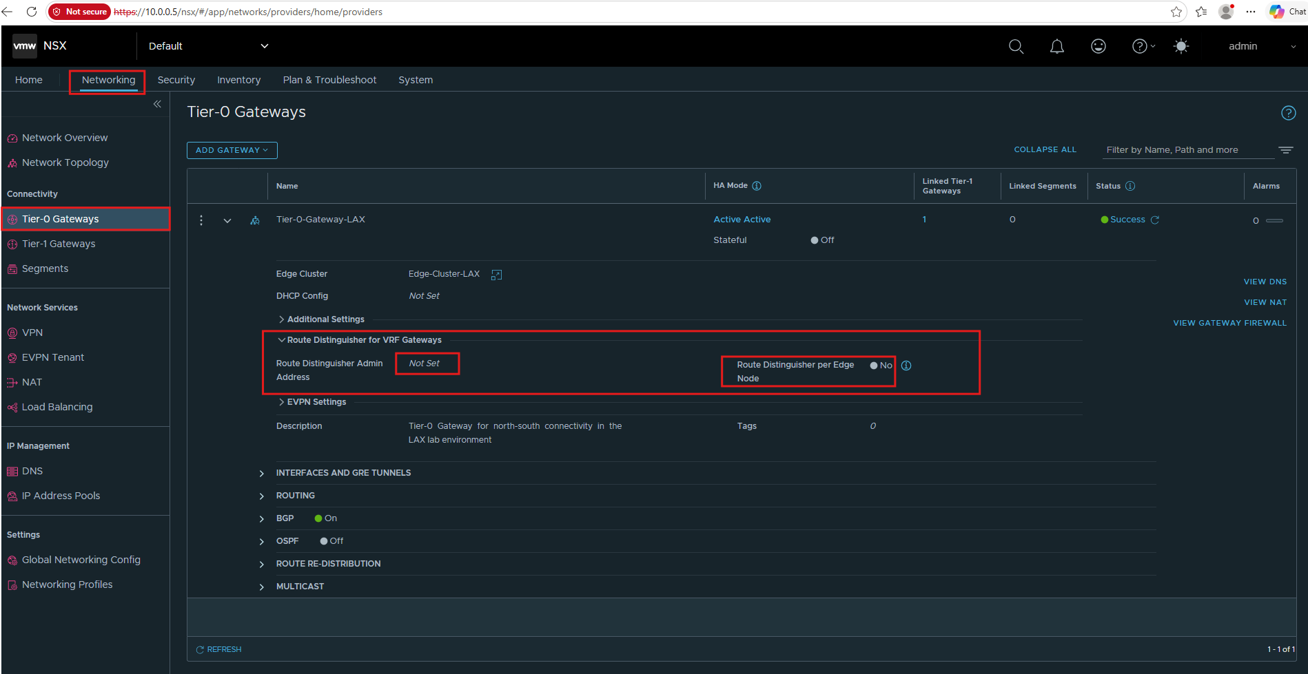
Earlier, when creating Tier-0-Gateway-LAX, we left the Route Distinguisher for VRF Gateways settings at their defaults. Now that we are introducing VRF Gateways, it is worth taking a closer look at these settings and explaining why we still do not need to configure them for our design.
The Route Distinguisher Admin Address and Route Distinguisher per Edge Node options are used when NSX automatically generates Route Distinguishers for VRF Gateways, particularly in EVPN-based deployments. A Route Distinguisher provides uniqueness for routes that may otherwise carry identical IP prefixes across different routing domains.
My lab, however, uses VRF-Lite with VLAN-separated external interfaces toward the VRF-aware Ubuntu router and does not use EVPN. Therefore, no Route Distinguisher configuration is required here, and we leave these settings unchanged.
EVPN (Ethernet VPN) is a BGP-based technology for exchanging Layer-2 and Layer-3 reachability information while maintaining separate tenant routing domains.
In EVPN deployments, Route Distinguishers (RDs) allow otherwise identical prefixes from different VRFs to remain uniquely identifiable; our VRF-Lite lab does not use EVPN, so these RD settings are not required.
We can now proceed with creating the first Tier-0 VRF Gateway for TenantA.
Create the Tier-0 VRF Gateway for TenantA
We can now create the first Tier-0 VRF Gateway, providing TenantA with its own isolated routing domain while sharing the Edge infrastructure of the parent Tier-0-Gateway-LAX.
This separation will later allow TenantA and TenantB to use overlapping IP address spaces without their routes conflicting.
In NSX Manager go to: Networking → Tier-0 Gateways → Add Gateway → VRF
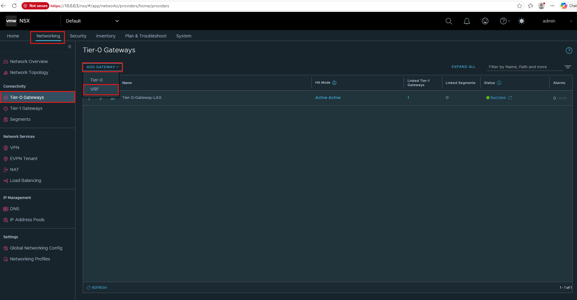
We create Tier-0-VRF-TenantA and connect it to our parent Tier-0-Gateway-LAX. The VRF Gateway provides TenantA with its own isolated routing table while sharing the Edge infrastructure and resources of the parent Tier-0.
- Name:
Tier-0-VRF-TenantA - Connect to Tier-0 Gateway:
Tier-0-Gateway-LAX - Description:
VRF Gateway for TenantA - DHCP Config: leave unset
- Tags: none
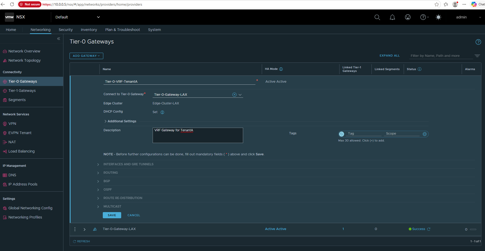
Then click Save.
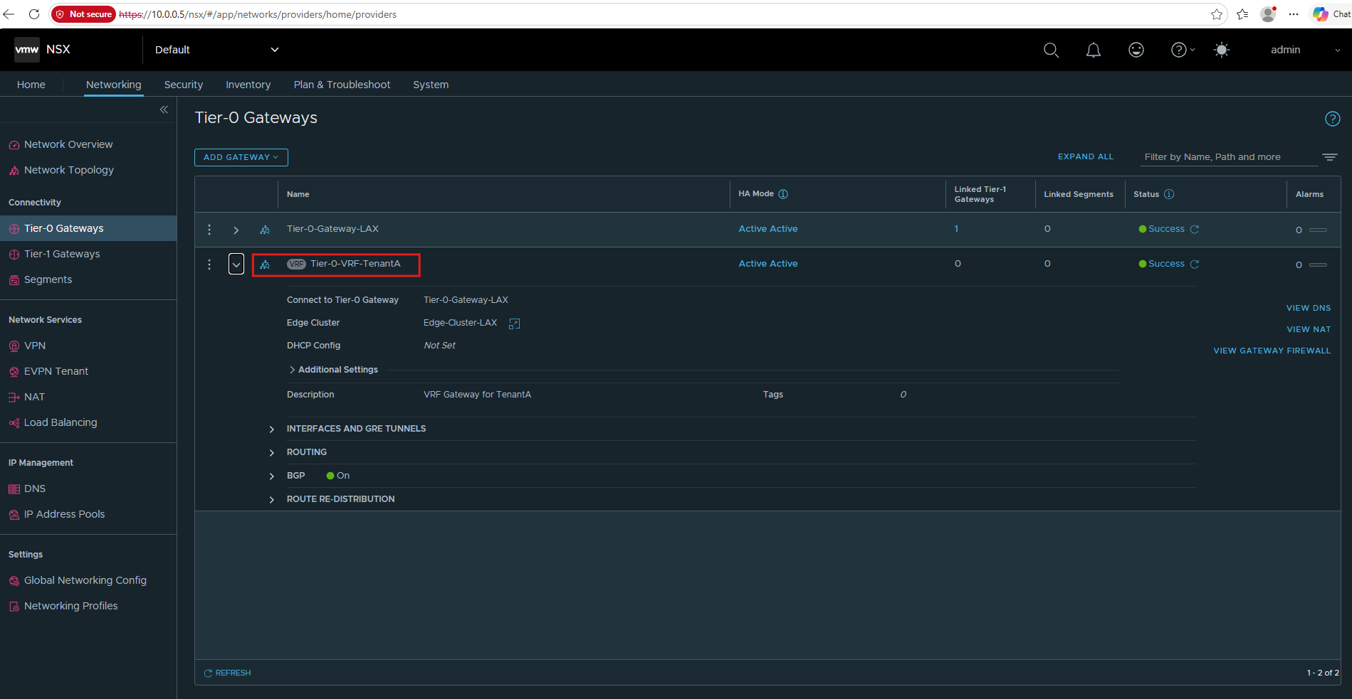
After that we’ll configure its external VRF interface/VLAN handoff toward Ubuntu.
Configure the TenantA VRF Uplink
Next, we provide Tier-0-VRF-TenantA with its own external Layer-3 handoff toward our VRF-aware Ubuntu router.
We use a dedicated VLAN for this connection, allowing multiple isolated VRF routing domains to share the same physical/virtual trunk while remaining logically separated.
For the external VRF handoffs, we will reuse VLAN 40 for TenantA and VLAN 41 for TenantB, which are already available in our physical lab infrastructure from the previous HNV series.
Each VLAN provides a separate Layer-3 path between the corresponding NSX Tier-0 VRF Gateway and Linux VRF on the Ubuntu router.
Create the VLAN Segment for TenantA
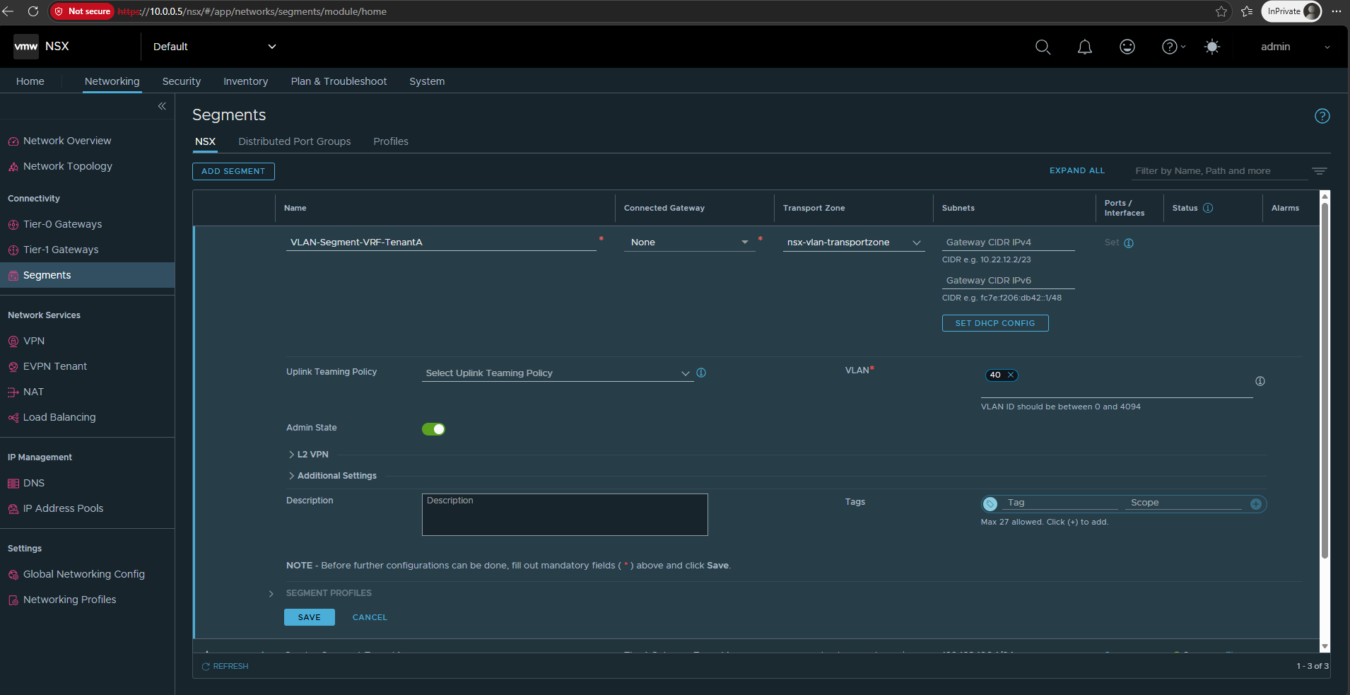
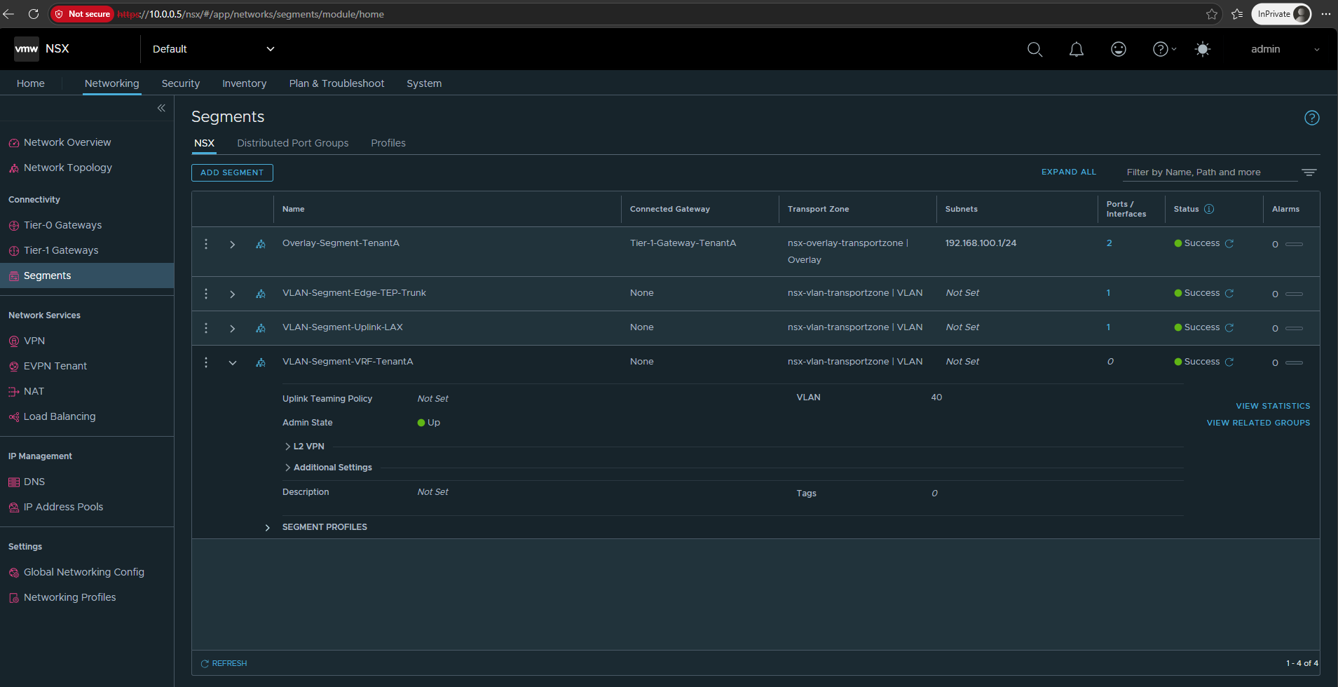
We first create a VLAN-backed NSX Segment using VLAN 40 for the TenantA VRF handoff. This segment provides the Layer-2 connection between the external interface of Tier-0-VRF-TenantA and the corresponding VLAN subinterface on our Ubuntu router.
Then in Networking → Segments → Add Segment, we’ll configure VLAN-Segment-VRF-TenantA on nsx-vlan-transportzone with VLAN 40 and no gateway/subnet.
For my lab I will use:
- Segment Name:
VLAN-Segment-VRF-TenantA - Connected Gateway:
None - Transport Zone:
nsx-vlan-transportzone - Gateway CIDR IPv4/IPv6: leave empty
- Uplink Teaming Policy: leave unset/default
- VLAN:
40 - Admin State: On
- DHCP: none
Then Save.
Configure the External Interface of the TenantA VRF Gateway
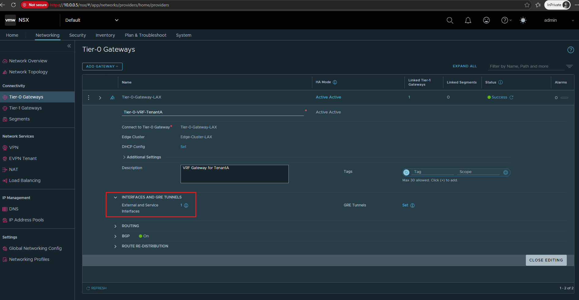
Next, we configure an external interface on Tier-0-VRF-TenantA and connect it to VLAN-Segment-VRF-TenantA. This interface provides the Layer-3 endpoint on the NSX side of the VLAN 40 handoff toward the TenantA Linux VRF on our Ubuntu router.
Go to: Networking → Tier-0 Gateways → Tier-0-VRF-TenantA → Interfaces
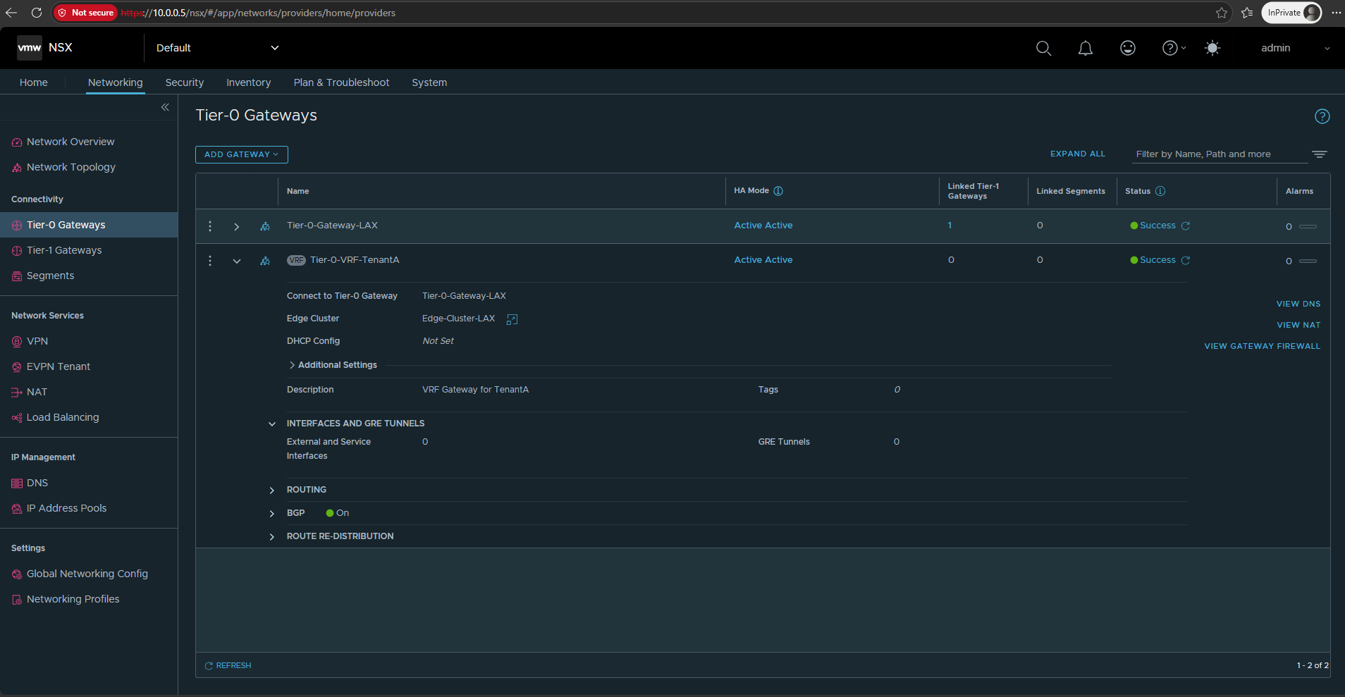
Click Edit on Tier-0-VRF-TenantA and Set next to External and Service Interfaces.
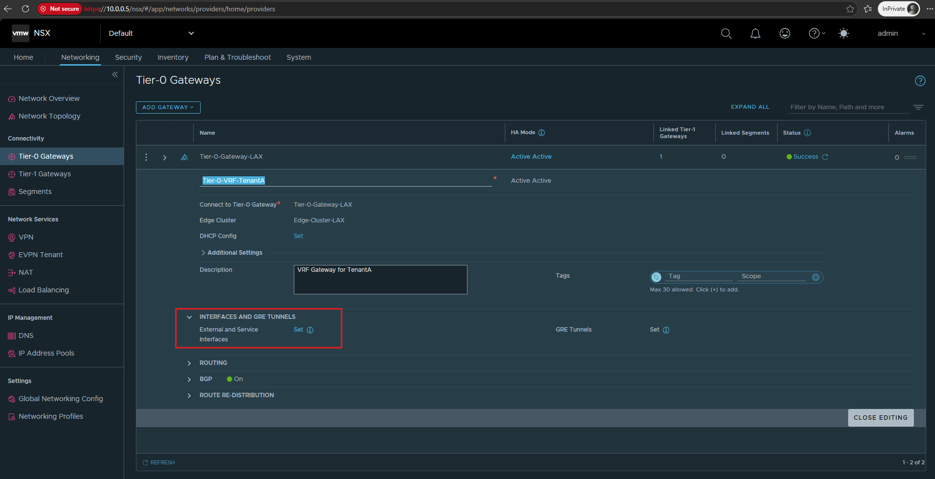
Now we need to define the point-to-point transit subnet between NSX and Ubuntu.
I will use a small dedicated subnet for each tenant, keeping it aligned with the VLAN number:
TenantA / VLAN 40: 10.0.40.0/30
NSX T0 VRF: 10.0.40.1/30
Ubuntu ens224.40: 10.0.40.2/30
We configure this interface as:
- Name:
Uplink-Ubuntu-TenantAType:External - IP Address / Mask:
10.0.40.2/30 - Connected To (Segment):
VLAN-Segment-VRF-TenantA - Edge Node:
Matrix-NSX-Edge01 - MTU: leave unset
- URPF Mode:
Strict - ND Profile:
default - Proxy ARP Filter: unset
- Access VLAN ID: unset
- Tags: none
ND Profile: The Neighbor Discovery (ND) Profile controls IPv6 Neighbor Discovery behavior on the interface, including functions comparable to ARP in IPv4. Since our VRF handoff uses IPv4, we leave the default profile unchanged.
uRPF Mode: Unicast Reverse Path Forwarding (uRPF) validates whether incoming traffic arrived through a valid path back toward its source address, helping prevent IP spoofing. We keep the default Strict mode, which requires the source to be reachable through the same interface on which the packet arrived.
Then Ubuntu will later get 10.0.40.1/30 on ens224.40.
Later TenantB can follow the same pattern with VLAN 41 / 10.0.41.0/30: Ubuntu .1, NSX .2.
Click on SAVE and CLOSE.
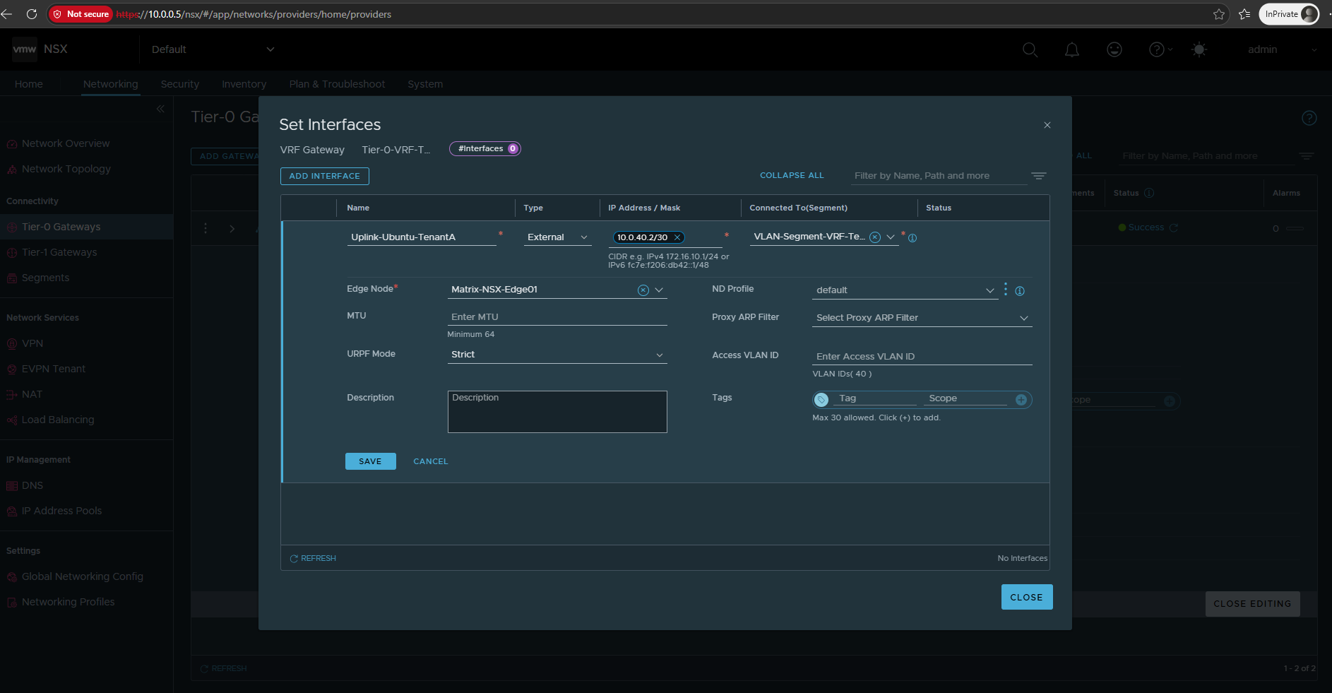
And CLOSE Editing, the next step is on the Ubuntu router: we create a VLAN subinterface
ens224.40, create the TenantA Linux VRF, attachens224.40to it, and assign10.0.40.1/30. Then we can test direct connectivity to the NSX VRF interface at10.0.40.2before adding any routes.
Configure the TenantA VRF and VLAN Interface on the Ubuntu Router
On the Ubuntu router, we now create the corresponding VLAN 40 subinterface and Linux VRF for TenantA. The VLAN interface provides the Layer-3 handoff to Tier-0-VRF-TenantA, while the Linux VRF maintains a separate routing table so TenantA remains isolated from other tenants.
On Linux, VLAN interfaces are virtual network interfaces that allow a single physical network adapter to carry traffic for multiple VLANs using IEEE 802.1Q tagging.
Each VLAN interface, such as
ens224.40, operates as a separate logical interface and can be assigned its own IP address and Linux VRF, allowing multiple isolated routing domains to share the same physical trunk connection.
We first verify the current Ubuntu network configuration and see that no Linux VRFs have been configured yet.
ip -br addr
ip link show type vrf
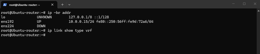
Since ens224 is our trunk and currently clean, we first create the TenantA VRF using routing table 1001, matching the scheme we used in the HNV lab series already.
We configure the VRF persistently using Netplan, ensuring that the configuration is automatically restored after a reboot.
The existing network configuration is generated by cloud-init and stored in
50-cloud-init.yaml.Instead of modifying this generated file, we create a separate Netplan configuration for the persistent TenantA VRF configuration.
ls -l /etc/netplan/
cat /etc/netplan/*.yaml
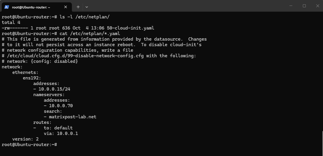
Create:
nano /etc/netplan/60-nsx-vrf.yaml
Use:
network:
  version: 2
  ethernets:
    ens224:
      dhcp4: false
  vlans:
    ens224.40:
      id: 40
      link: ens224
      addresses:
        - 10.0.40.1/30
  vrfs:
    vrf-tenantA:
      table: 1001
      interfaces:
        - ens224.40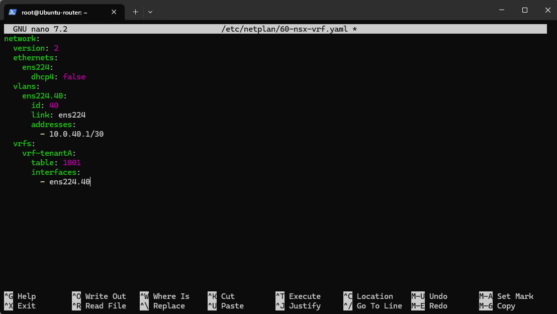
Then before applying it, validate the configuration:
Netplan configuration files should only be accessible by
root. We therefore restrict the permissions of the new configuration file and validate the configuration before applying it.
netplan generate
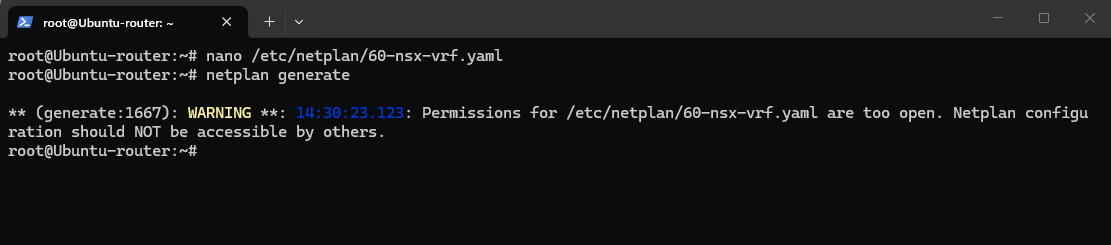
The no output this time confirms that the configuration passes validation
chmod 600 /etc/netplan/60-nsx-vrf.yaml
netplan generate
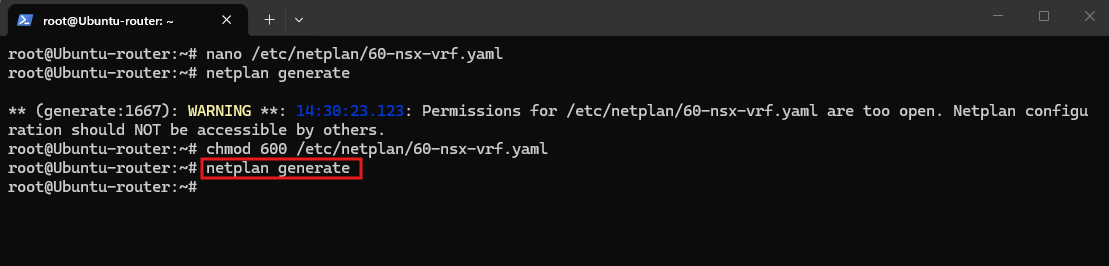
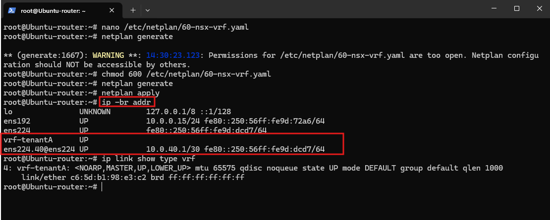
We can now apply it and verify that vrf-tenantA and ens224.40 have been created correctly.
After applying the Netplan configuration, we verify the resulting interface state. The output confirms that the trunk interface
ens224, thevrf-tenantAdevice, and the VLAN 40 subinterfaceens224.40are all up, with10.0.40.1/30assigned to the TenantA VLAN interface.We also verify that the
vrf-tenantAVRF device has been created successfully.
netplan apply
ip -br addr
ip link show type vrf
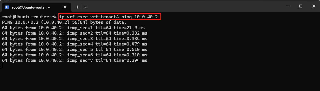
Finally, we verify the Layer-3 handoff from the Ubuntu vrf-tenantA routing domain to the external interface of Tier-0-VRF-TenantA at 10.0.40.2.
The successful ping confirms that the VLAN 40 handoff between the Linux VRF and the NSX VRF Gateway is working correctly.
This command is important because it deliberately executes the ping inside the TenantA VRF.
ip vrf exec vrf-tenantA ping 10.0.40.2
Configure TenantA Workload Routing
Now that the VRF-aware upstream routing infrastructure is in place, we can connect the TenantA workload network to its isolated routing domain. We will create the Tier-1 Gateway for TenantA, connect the overlay segment, and configure the tenant VMs to use it as their default gateway.
Create the Tier-1 Gateway for TenantA
With the Tier-0 VRF Gateway for TenantA and its dedicated upstream handoff toward the VRF-aware Ubuntu router in place, we can now create the Tier-1 Gateway for TenantA.
The Tier-1 Gateway provides routing for the TenantA workload network and handles connectivity between its connected NSX segments. For north-south connectivity, it will be connected upstream to Tier-0-VRF-TenantA, keeping TenantA within its dedicated routing domain.
Navigate to Networking → Tier-1 Gateways and click Add Tier-1 Gateway to create the logical gateway for our TenantA workload network and connect it upstream to the previously configured Tier-0-VRF-TenantA.
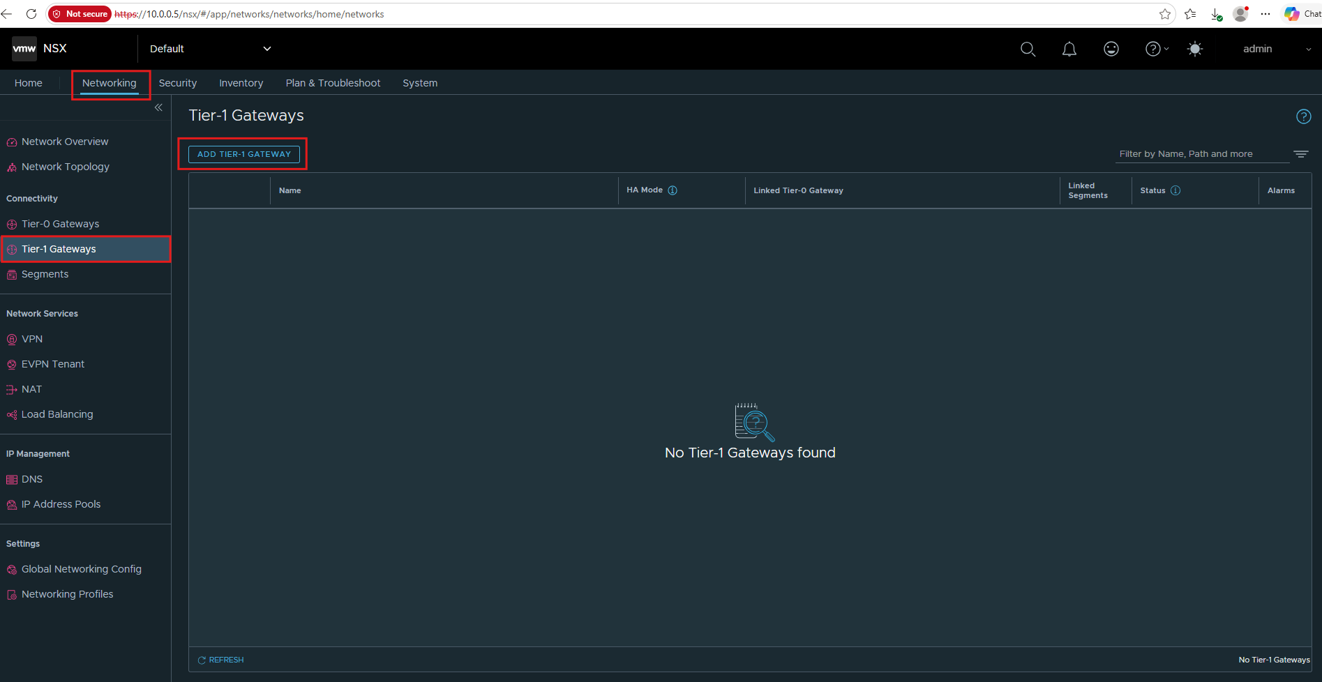
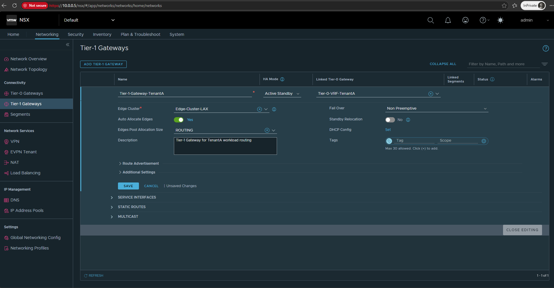
Here we configure the Tier-1 Gateway itself.
- Name:
Tier-1-Gateway-TenantA - HA Mode:
Active Standby - Linked Tier-0 Gateway:
Tier-0-VRF-TenantA - Edge Cluster:
Edge-Cluster-LAX - Description:
Tier-1 Gateway for TenantA workload routing
Leave Edges Pool Allocation Size, DHCP Config, and the remaining settings at their defaults for now, then click Save.
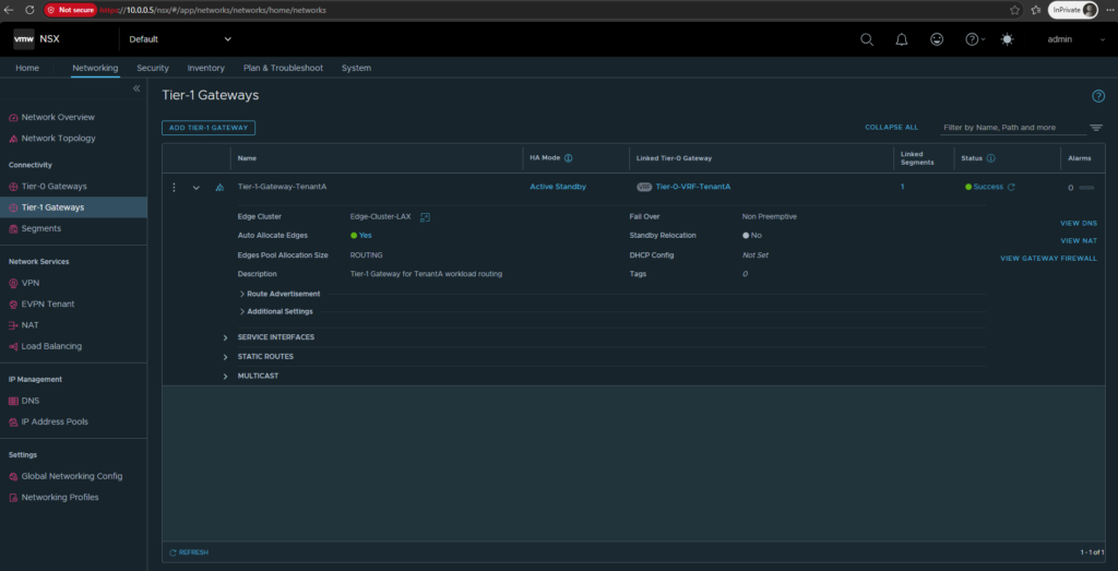
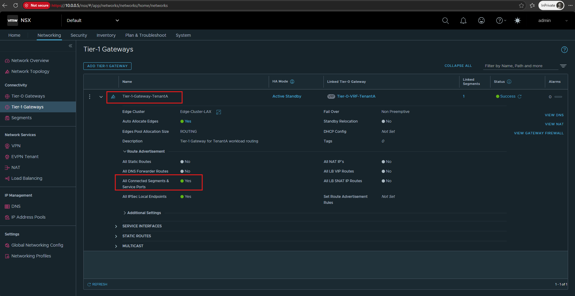
After saving the configuration, Tier-1-Gateway-TenantA reports Success and is linked to our Tier-0-VRF-TenantA.
The Tier-1 Gateway is now ready to provide Layer 3 routing for the TenantA workload network within its dedicated VRF routing domain.
Next, we enable Route Advertisement for the connected TenantA segment so that its 192.168.100.0/24 network is advertised from the Tier-1 Gateway toward the linked Tier-0-VRF-TenantA.
Enable All Connected Segments & Service Ports and click SAVE.
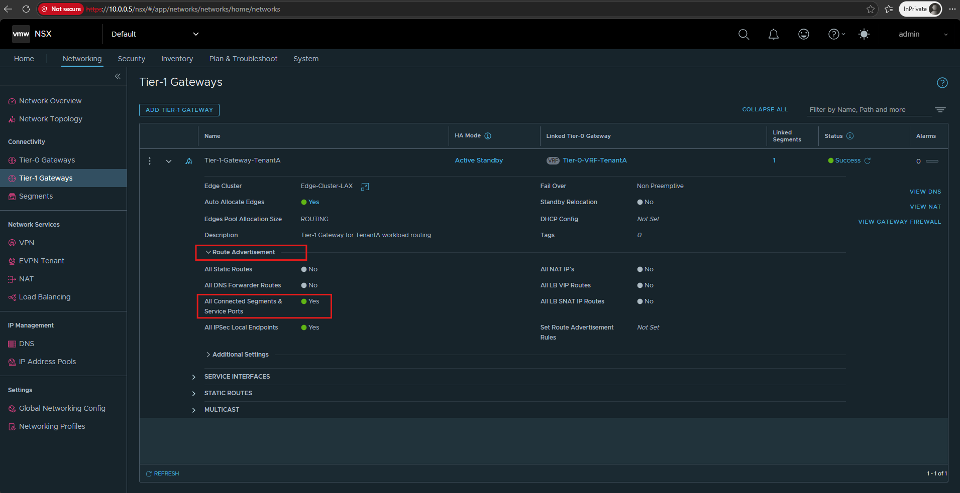
Now click Close Editing
After saving the configuration, we can verify that All Connected Segments & Service Ports is now enabled on
Tier-1-Gateway-TenantA, llowing its connected TenantA network to be advertised towardTier-0-VRF-TenantA.
Connect the TenantA Segment to the Tier-1 Gateway
Next we connect the existing Overlay-Segment-TenantA to the new Tier-1 Gateway and give the tenant network its default gateway.
Unlike Microsoft HNV and Azure Virtual Networks, which automatically use the first usable IP address of the subnet (
.1) as the default gateway, with NSX we explicitly configure this gateway address on the segment.
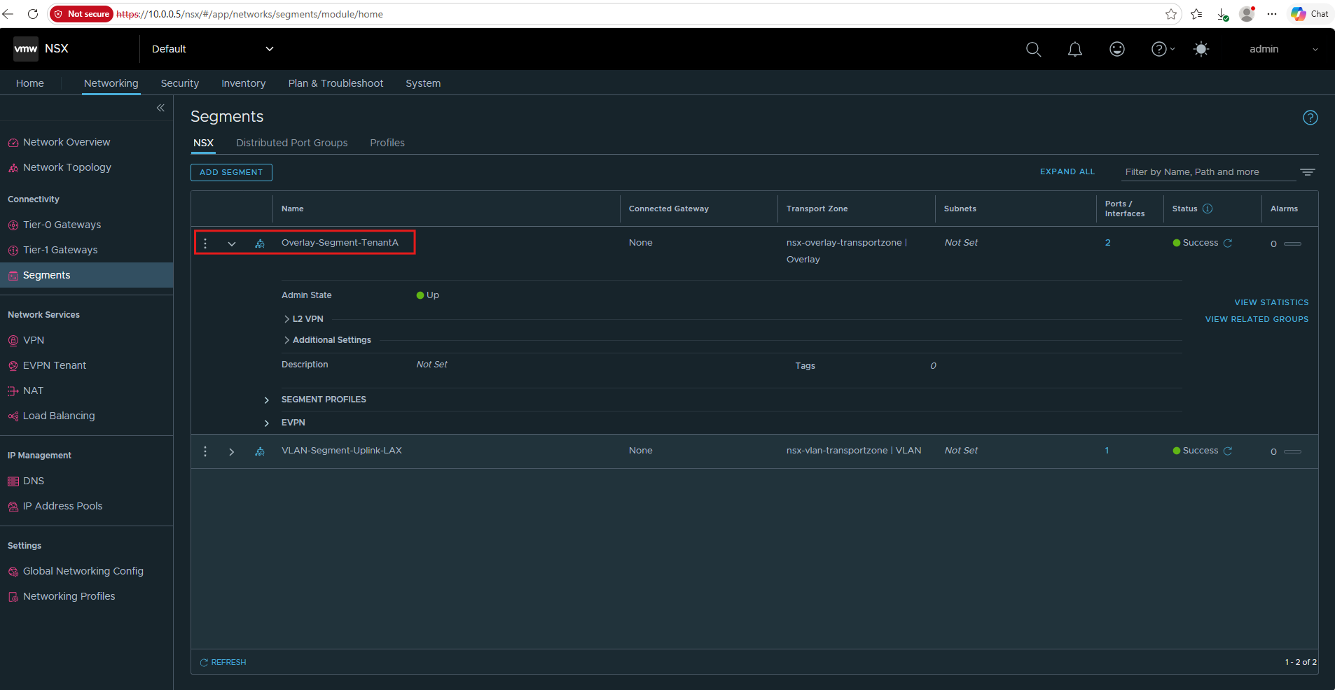
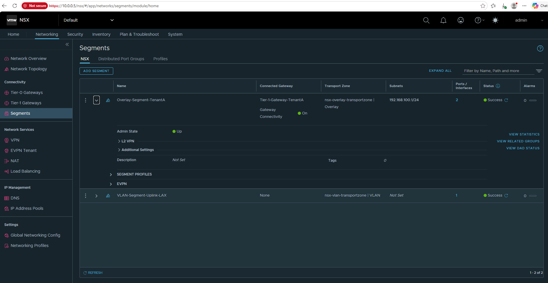
Go to Networking → Segments, expand/edit Overlay-Segment-TenantA, and change:
Connected Gateway: Tier-1-Gateway-TenantA
Subnet / Gateway: 192.168.100.1/24
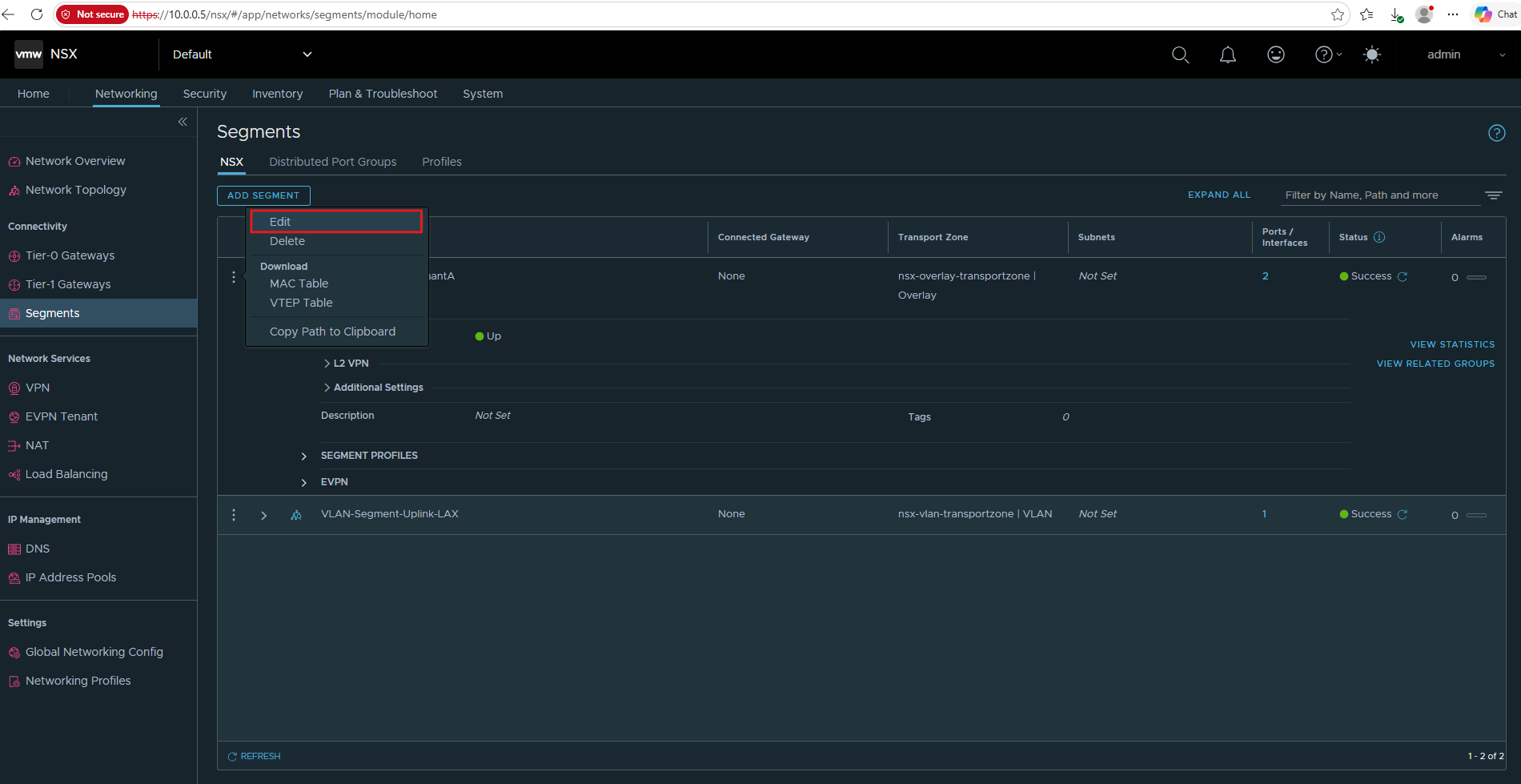
Click on Save.
This is the important transition: until now the segment was pure Layer 2. Once connected to the Tier-1 with
192.168.100.1/24, NSX provides the default gateway for192.168.100.0/24and enables Layer 3 connectivity beyond the segment.
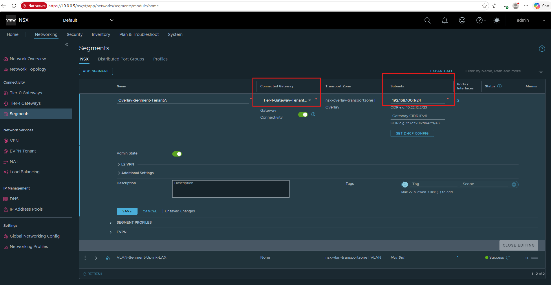
Click Close Editing. That exits edit mode and returns to the normal segment overview, where we can verify that Tier-1-Gateway-TenantA and 192.168.100.1/24 were actually persisted.
After closing the editor, we can verify that Overlay-Segment-TenantA is now connected to Tier-1-Gateway-TenantA with the gateway 192.168.100.1/24.
The segment reports Success, and the Tier-1 Gateway now provides the Layer 3 default gateway for our TenantA workloads.
Configure the TenantA VMs with the Tier-1 Default Gateway
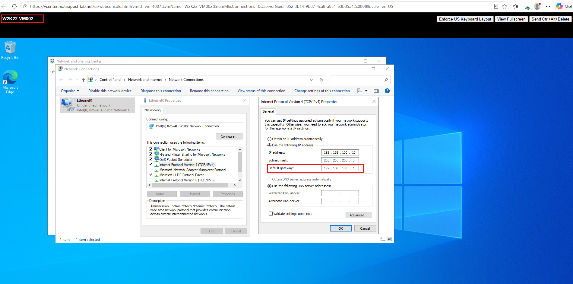
Now we configure the existing TenantA VMs to use the new Tier-1 gateway address 192.168.100.1 as their default gateway:
W2K22-VM002 → 192.168.100.10/24, Gateway 192.168.100.1
W2K22-VM003 → 192.168.100.11/24, Gateway 192.168.100.1
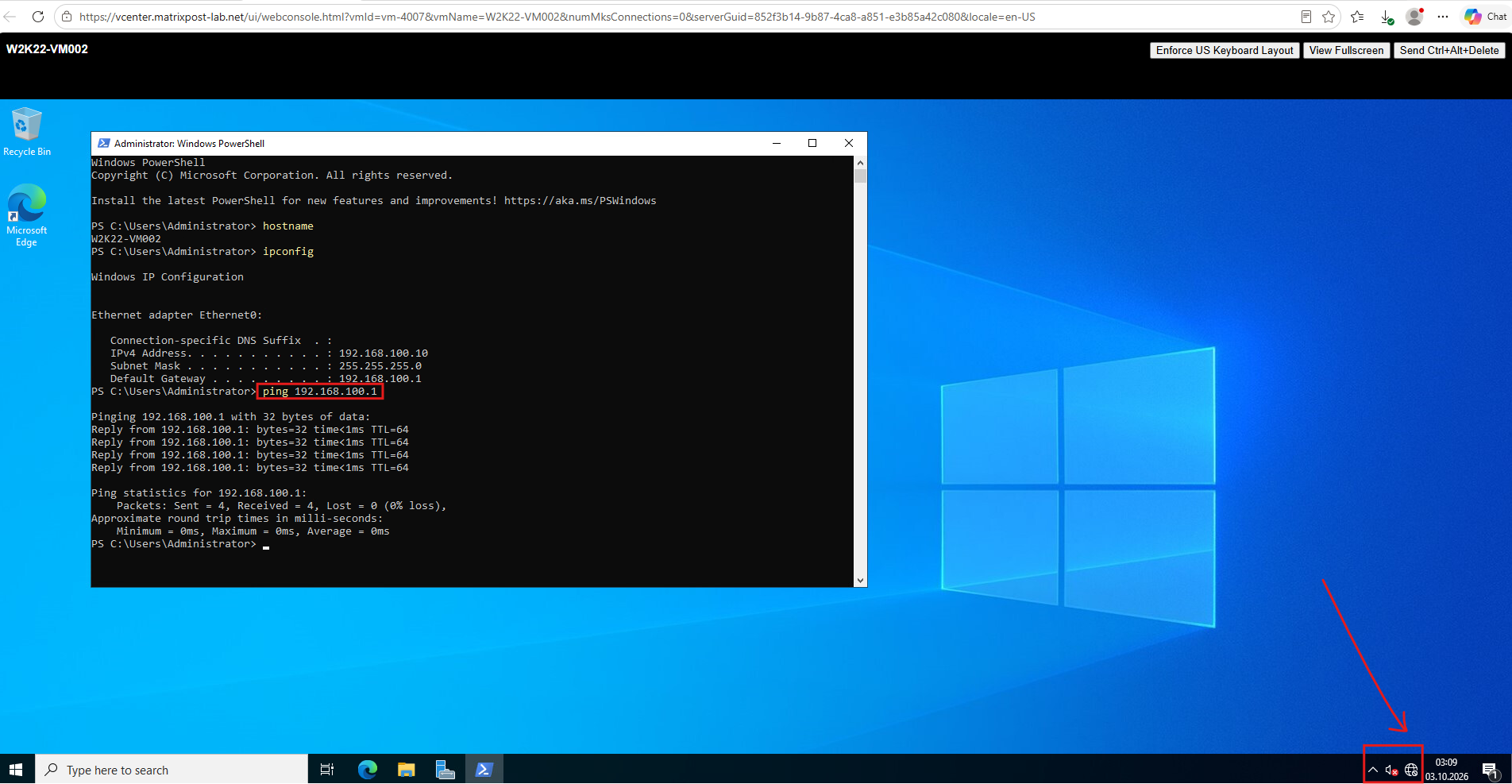
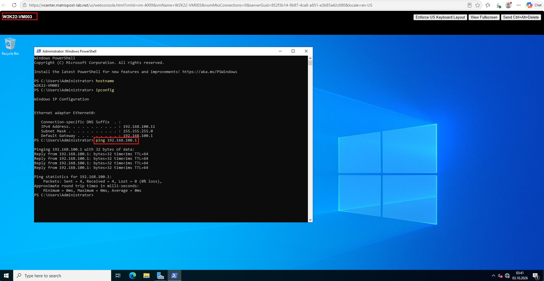
Afterwards, first test ping 192.168.100.1 from one of the VMs. That verifies the workload can reach the NSX distributed Tier-1 gateway before we test north-south connectivity through Tier-0 → Edge → upstream VRF-aware Ubuntu router.
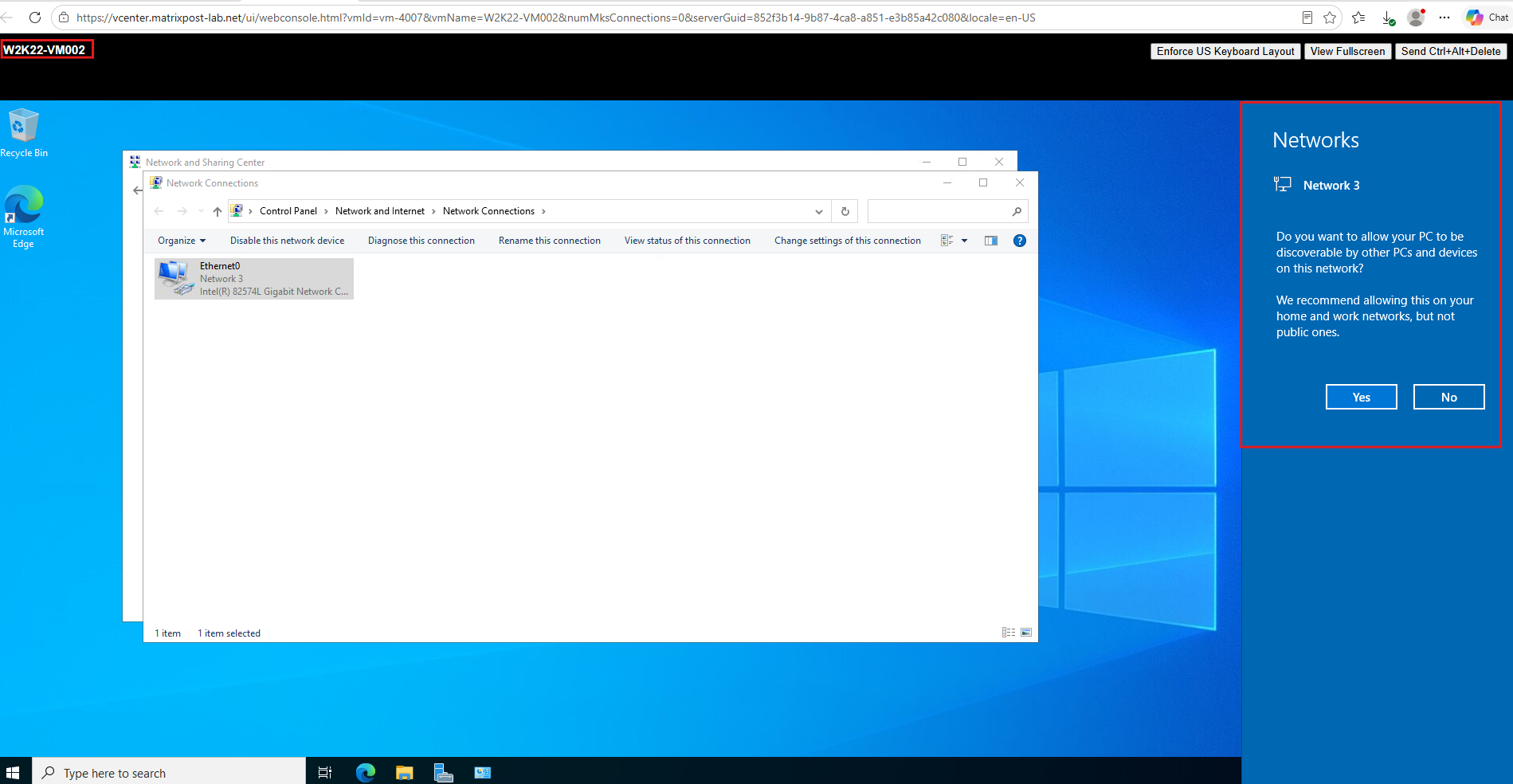
After configuring the new default gateway, Windows may detect a change in network connectivity and display the “Do you want to allow your PC to be discoverable…” prompt.
This indicates that Windows is re-evaluating the network profile, although we will verify actual gateway connectivity separately with a ping.
The successful ping to 192.168.100.1 confirms that our Tier-1 Gateway is reachable from TenantA and now provides the default gateway for the workload network.
At this point, the Windows system tray still shows the globe icon, indicating that Windows has not detected Internet connectivity yet; once its Network Connectivity Status Indicator (NCSI) connectivity checks can successfully reach the Internet, the icon changes to the normal connected network icon.
Windows NCSI verifies Internet connectivity by resolving Microsoft probe hosts such as
dns.msftncsi.comand retrievingwww.msftconnecttest.com/connecttest.txt. The web probe must return the expected “Microsoft Connect Test” response before NCSI can confirm Internet connectivity.Source: https://learn.microsoft.com/en-us/troubleshoot/windows-server/networking/troubleshoot-ncsi-guidance
The same test on W2K22-VM003 (192.168.100.11) also successfully reaches the Tier-1 gateway at 192.168.100.1, confirming gateway connectivity from both TenantA workloads.
Configure TenantA Routing Between NSX and Ubuntu
With the TenantA workload network now connected to Tier-0-VRF-TenantA, we can complete the Layer 3 routing between the NSX VRF and the corresponding Linux VRF on the Ubuntu router.
This requires routes in both directions so that 192.168.100.0/24 can communicate through the VLAN 40 handoff.
First, we add a persistent return route for the TenantA workload network to the Netplan configuration. The destination 192.168.100.0/24 is reachable through the external interface of Tier-0-VRF-TenantA at 10.0.40.2, which is realized on the NSX Edge Node and connected to the Ubuntu router through VLAN 40.
The route is configured on the TenantA VLAN interface ens224.40, which is already assigned to vrf-tenantA. This ensures that traffic toward the TenantA workload network is forwarded through the actual VLAN 40 interface.
And extend the existing vrf-tenantA section in /etc/netplan/60-nsx-vrf.yaml:
  vlans:
  ens224.40:
    id: 40
    link: ens224
    addresses:
      - 10.0.40.1/30
    routes:
      - to: 192.168.100.0/24
        via: 10.0.40.2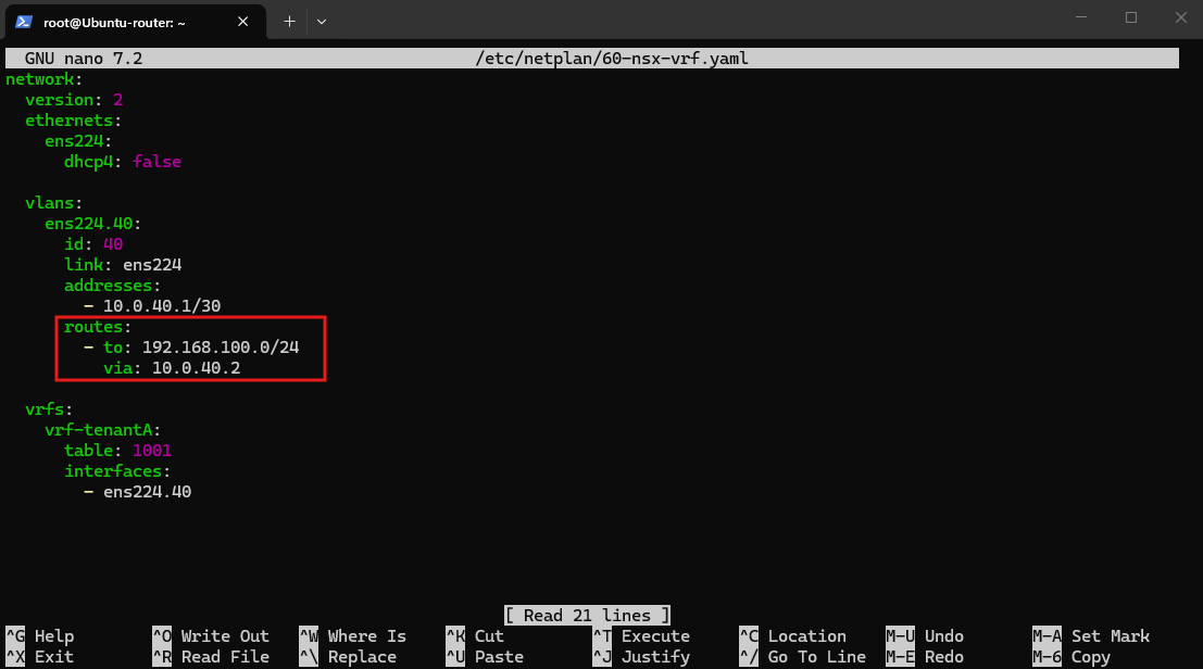
Then:
netplan generate
netplan apply

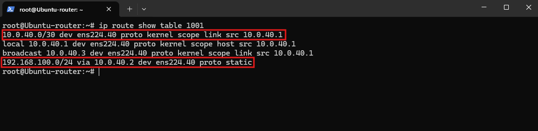
The routing table confirms that 10.0.40.0/30 is directly connected through the TenantA VLAN interface ens224.40. The TenantA workload network 192.168.100.0/24 is routed via the NSX Tier-0 VRF Gateway at 10.0.40.2, also using ens224.40.
This establishes the return path from the Ubuntu TenantA VRF toward the NSX workload network, with the static route correctly using the VLAN 40 interface as its outgoing interface.
ip route show table 1001
Configure the Default Route on the TenantA Tier-0 VRF Gateway
With the return route configured on Ubuntu, we now configure the opposite direction on Tier-0-VRF-TenantA.
A default route through 10.0.40.1 forwards traffic that is not known inside the TenantA NSX routing domain toward the corresponding Linux VRF on the Ubuntu router.
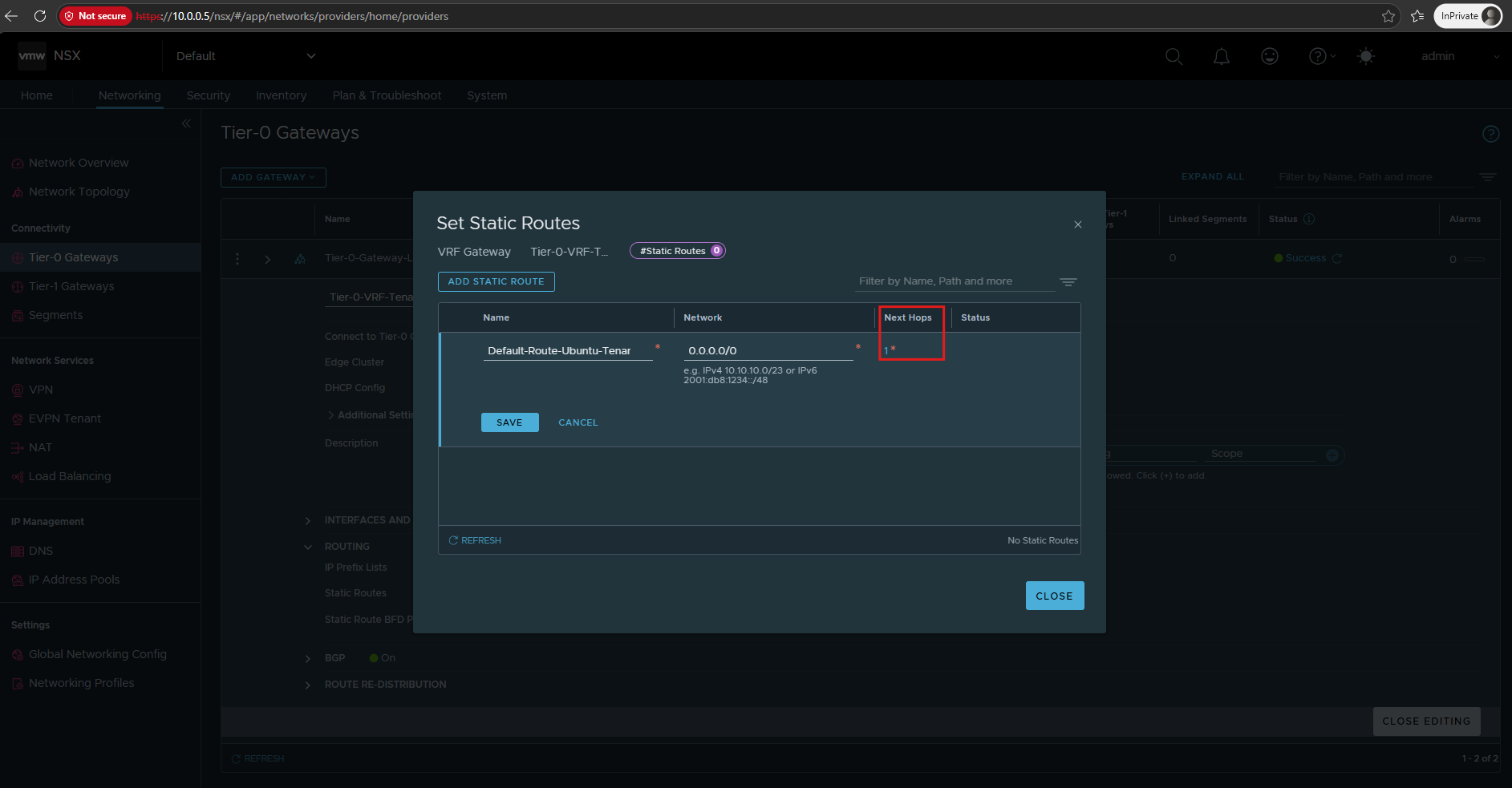
In NSX go to: Networking → Tier-0 Gateways → Tier-0-VRF-TenantA → Routing → Static Routes → Set → Add Static Route
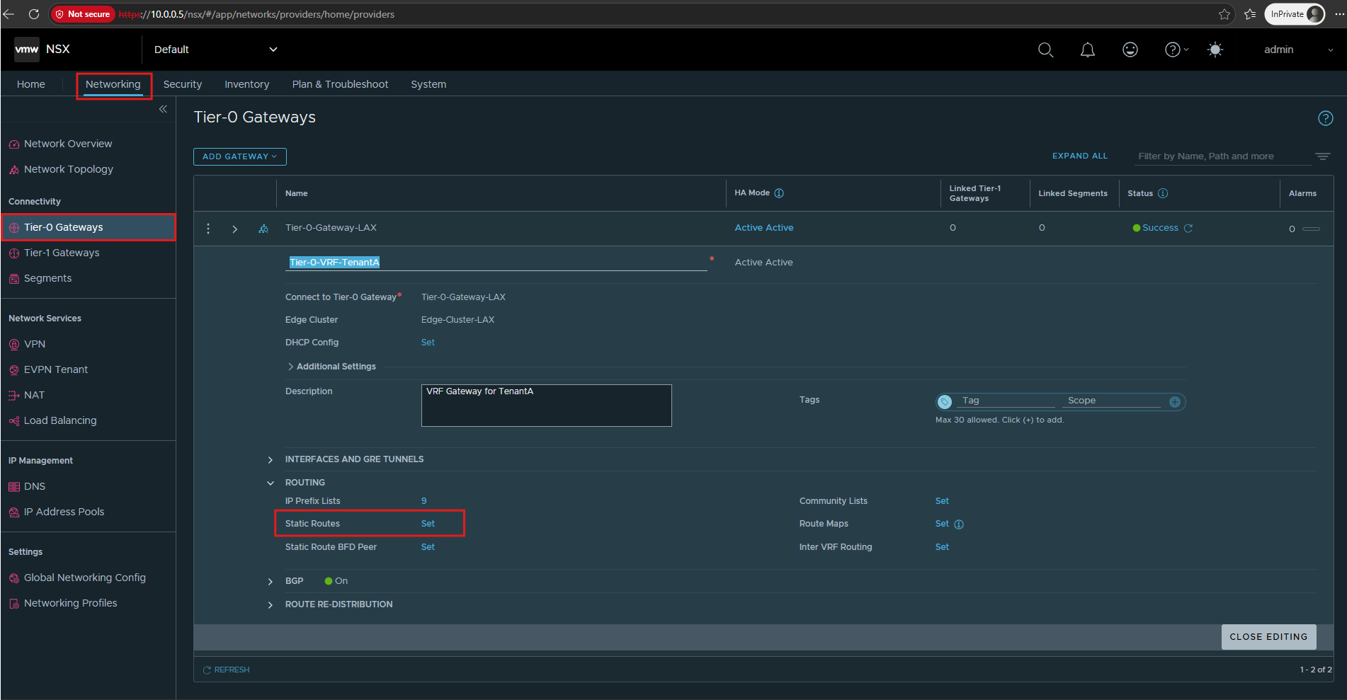
Click Add Static Route and create the default route that forwards traffic from Tier-0-VRF-TenantA toward the TenantA Linux VRF on the Ubuntu router.
Default-Route-Ubuntu-TenantA
Network: 0.0.0.0/0
Then click Set under Next Hops. There we’ll configure 10.0.40.1 as the next hop.
After saving the configuration, Tier-0-VRF-TenantA now contains one static route.
The default route
0.0.0.0/0forwards traffic that is not known within the TenantA NSX routing domain toward the corresponding Linux VRF on the Ubuntu router at10.0.40.1.
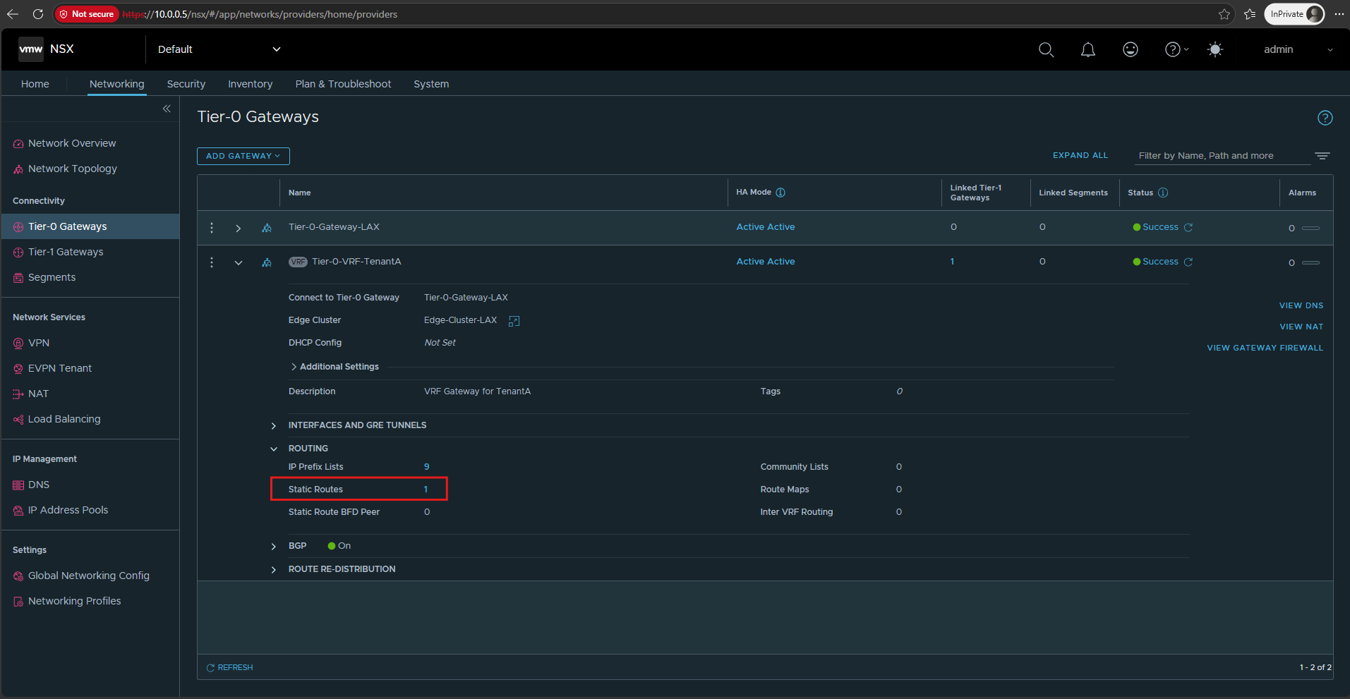
Now the routing is established in both directions:
TenantA workload → Tier-1 → Tier-0 VRF → 10.0.40.2 → VLAN 40 → Ubuntu 10.0.40.1
and the Ubuntu VRF knows how to return:
Ubuntu vrf-tenantA → ens224.40 → 10.0.40.2 → Tier-0 VRF → Tier-1 → 192.168.100.0/24
Verify End-to-End TenantA Routing
Finally, we verify the complete routing path from the TenantA workload network to the corresponding Linux VRF on the Ubuntu router.
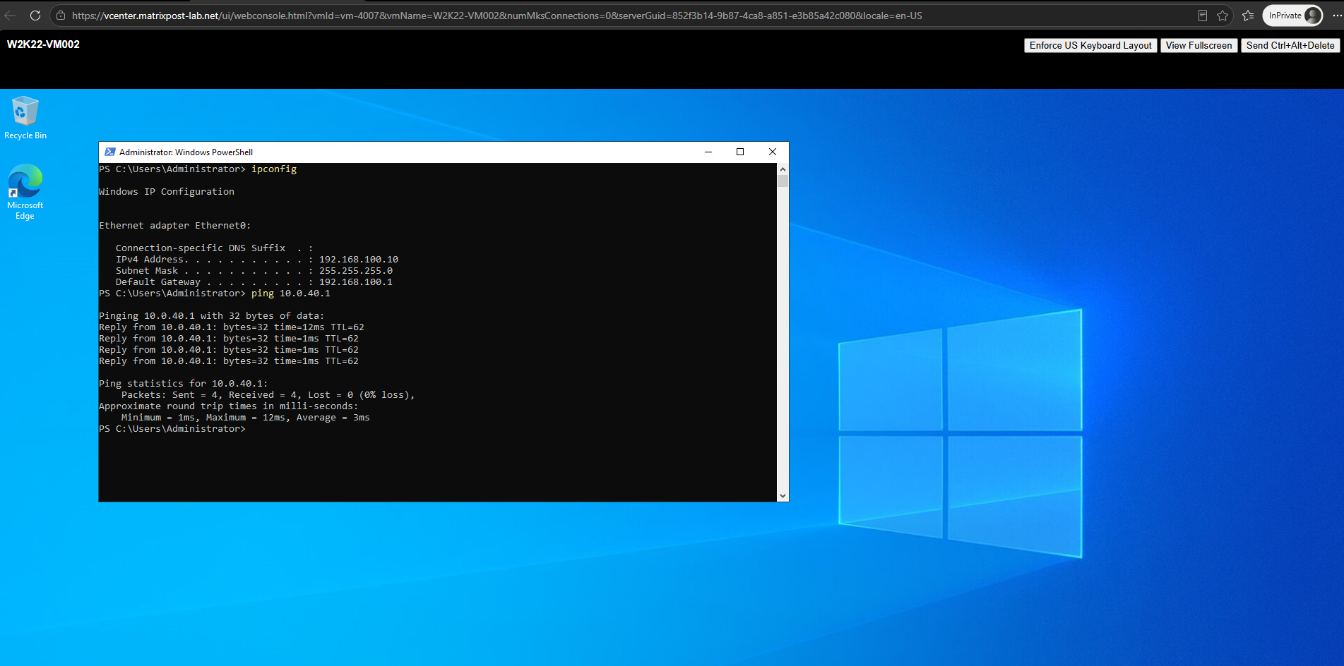
From W2K22-VM002 (192.168.100.10), we ping the Ubuntu TenantA VRF interface at 10.0.40.1.
The successful replies confirm that bidirectional routing is working across the complete path from the TenantA overlay network through the Tier-1 and Tier-0 VRF Gateway, across the VLAN 40 handoff, to the Ubuntu
vrf-tenantArouting domain.
Configure the Ubuntu Router for Upstream Internet Connectivity
With the isolated TenantA routing path now working, we can extend the Ubuntu router toward the external network and Internet. The Ubuntu router will replace pfSense at 10.0.0.1 on the lab network and use an additional interface connected through VLAN 100 to my FritzBox network (192.168.0.0/24) as its upstream/WAN connection.
At this point, ens192 still uses the temporary address 10.0.0.15/24 and its default route points to the now powered-off pfSense at 10.0.0.1. Therefore, Internet connectivity is currently unavailable, as confirmed by the failed ping to 8.8.8.8.
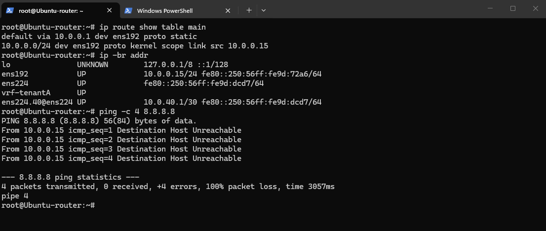
Next, we add a third network adapter to the Ubuntu router and connect it to DPortGroup-VLAN-100 (WAN). This interface provides the upstream connection to the FritzBox network (192.168.0.0/24) and will become the router’s path toward the Internet.
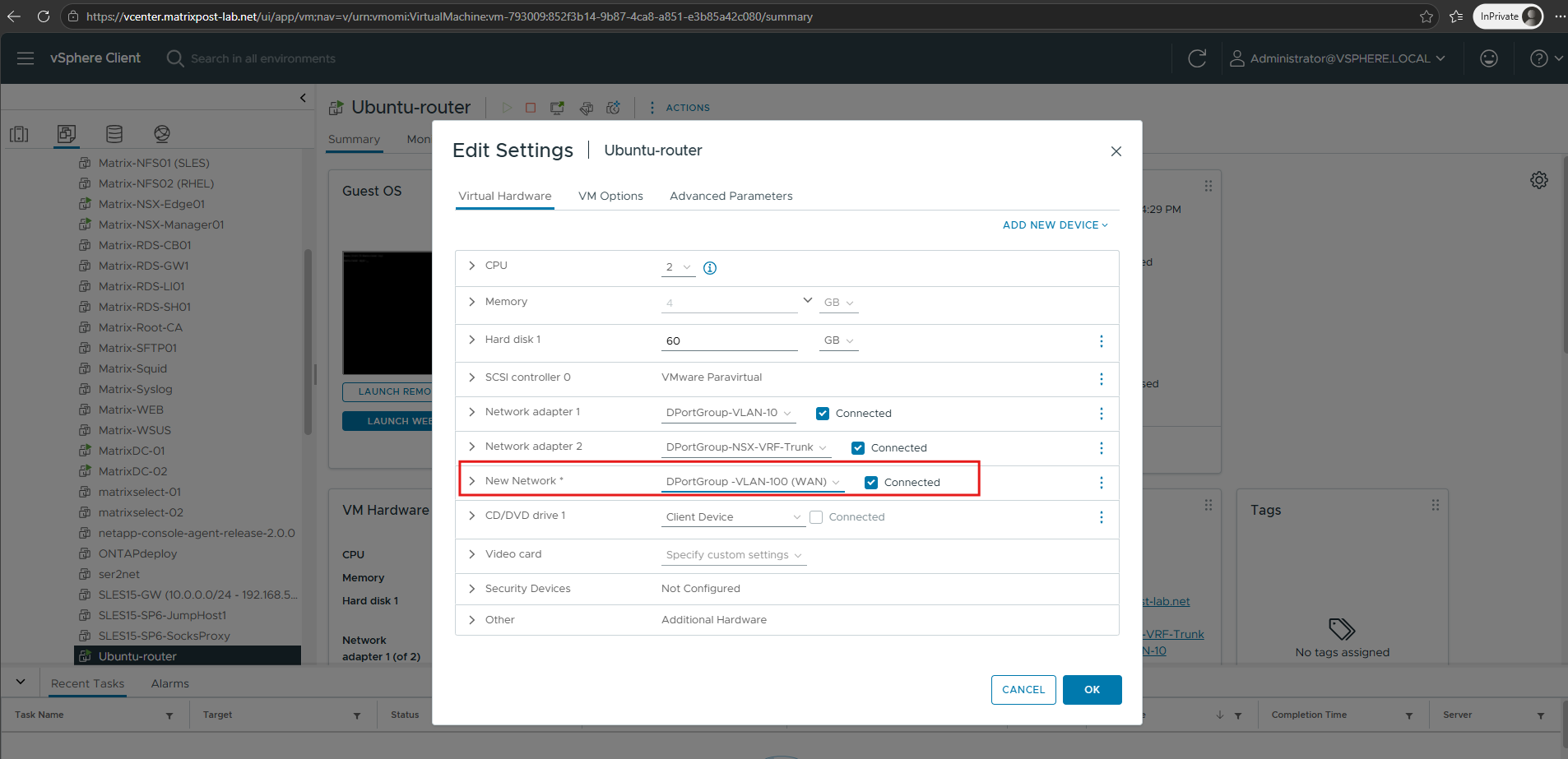
Then we enable DHCP on the newly added WAN interface ens256, connected to DPortGroup-VLAN-100 (WAN), by updating the Netplan configuration.
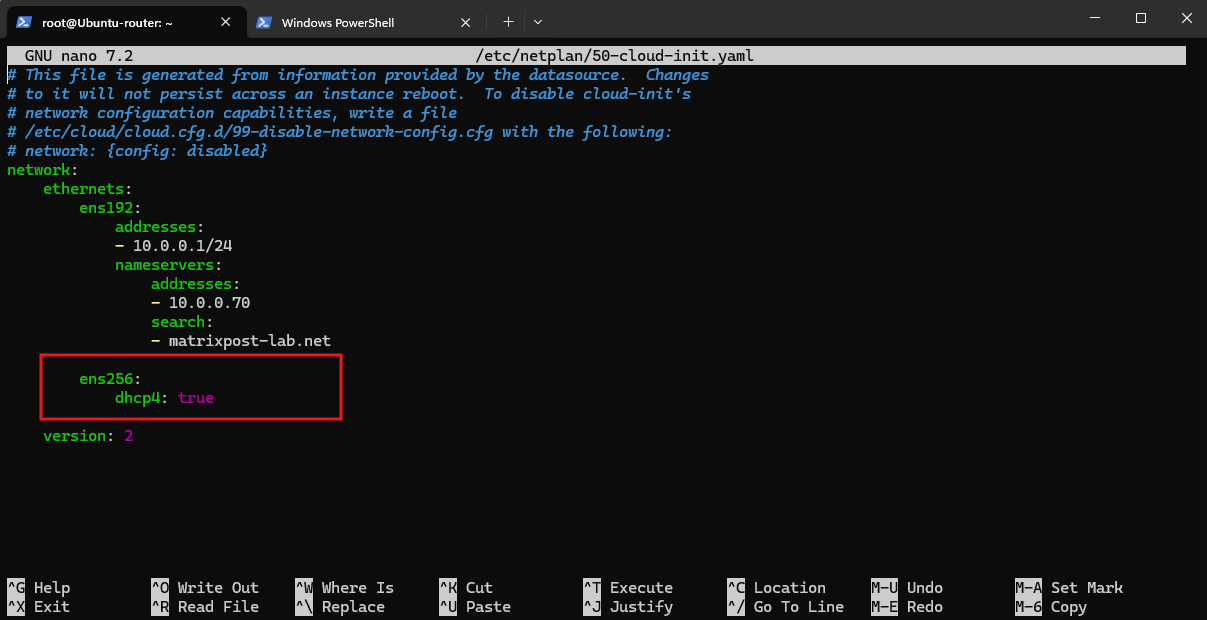
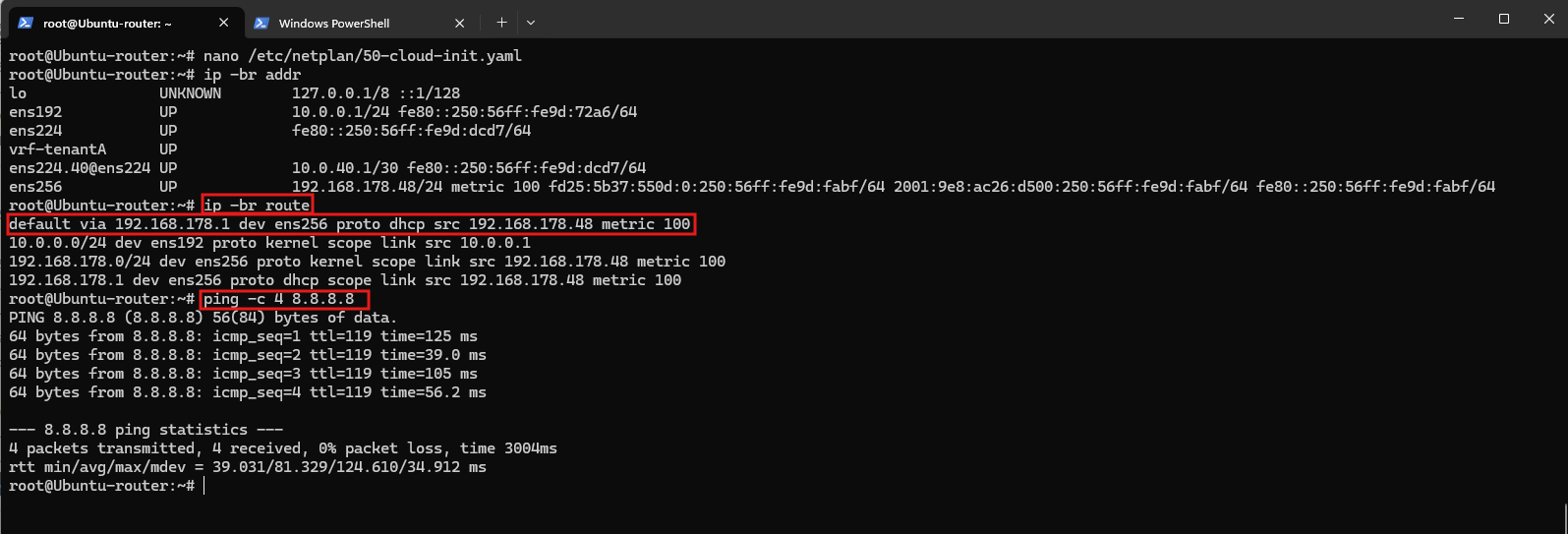
After applying the changes, the interface successfully receives 192.168.178.48/24 from the FritzBox network, establishing the router’s WAN-side network connectivity.

The routing table confirms that the default route is now provided by the FritzBox at 192.168.178.1 through the WAN interface ens256.
A successful ping to
8.8.8.8verifies that the Ubuntu router can reach the Internet through VLAN 100.
ip -br route
ping -c 4 8.8.8.8
Configure Internet Access and NAT for TenantA
With the Ubuntu router now connected to the Internet through the FritzBox, we can extend Internet connectivity to our isolated TenantA workload network.
To achieve this, we need to configure routing and Network Address Translation (NAT) between the TenantA Linux VRF (vrf-tenantA) and the WAN interface ens256.
Our configuration must preserve the separation between tenant routing domains, allowing us to introduce additional tenants with overlapping IP address ranges later.
Verify the Current Routing and Forwarding Configuration
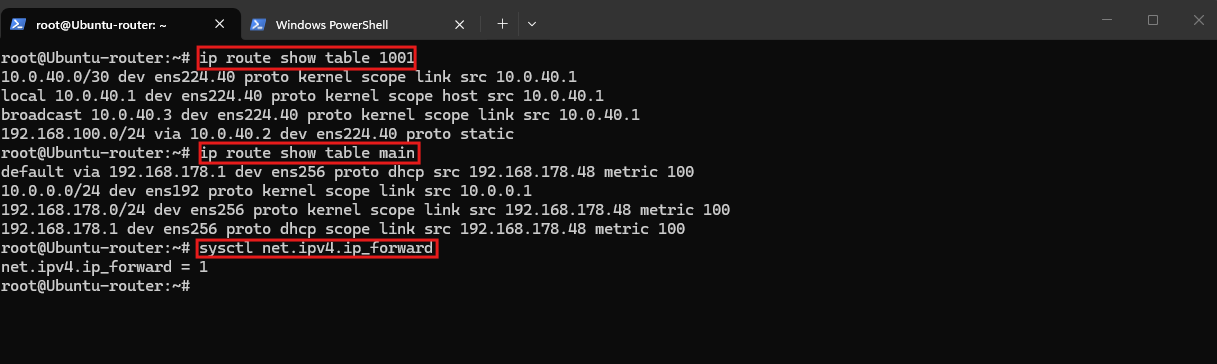
Before configuring NAT and Internet access for TenantA, we verify the existing VRF and main routing tables, along with IPv4 forwarding on the Ubuntu router.
The output confirms that TenantA routing is correctly configured in table
1001, the main routing table provides Internet connectivity throughens256and the FritzBox (192.168.178.1), and IPv4 forwarding is enabled.
ip route show table 1001
ip route show table main
sysctl net.ipv4.ip_forward
Configure the Default Route for the TenantA Linux VRF
Our vrf-tenantA currently knows how to reach the NSX workload network (192.168.100.0/24), but it has no default route for Internet-bound traffic.
The Ubuntu router’s main routing table already has a working default route through ens256. However, Linux VRFs maintain separate routing tables, so that route is not automatically available to TenantA.
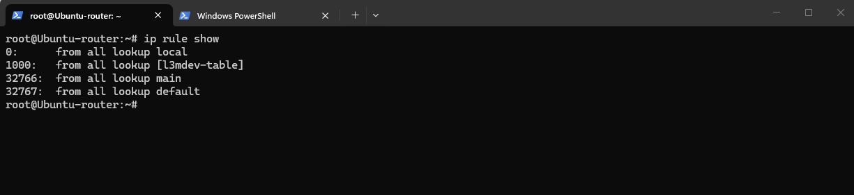
First we inspect the Linux Routing Policy Database (RPDB), which determines which routing table is consulted when forwarding packets. This is particularly important for our VRF-based design, where each tenant maintains its own isolated routing table.
The output shows four policy-routing rules, evaluated in order of priority (lower numbers first):
0 – local: Looks up local IP addresses and system-managed local routes.
1000 – l3mdev-table: Selects the routing table associated with a Linux VRF. Forvrf-tenantA, this is table 1001.
32766 – main: Uses the main routing table, which contains our default route toward the FritzBox throughens256.
32767 – default: Consults the normally empty default routing table as a final fallback.
ip rule show
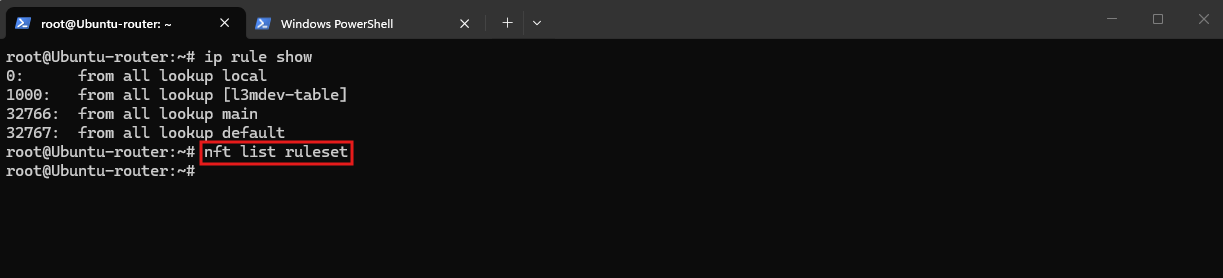
Before configuring Internet access for TenantA, we check whether any existing nftables rules could affect packet forwarding or Network Address Translation (NAT).
On the Ubuntu router, we run:
The empty output of
nft list rulesetconfirms that no nftables firewall or NAT rules are currently configured on the Ubuntu router. We can therefore proceed with implementing tenant-specific NAT and forwarding rules without interfering with existing nftables policies.nftables is the modern Linux firewall framework and successor to iptables, built on top of the Linux kernel’s Netfilter subsystem, which handles packet filtering, Network Address Translation (NAT), and packet processing. The
nftcommand-line utility is used to configure and manage the Netfilter rules through nftables.
nft list ruleset
Now that we’ve verified the routing tables, IPv4 forwarding, and the empty nftables ruleset, we can start configuring Internet access for TenantA.
The challenge is that vrf-tenantA uses routing table 1001, while the WAN interface ens256 belongs to the main routing table. We need a controlled path between these routing domains without losing the isolation required for overlapping tenant networks.
Verify TenantA Traffic Forwarding to the WAN
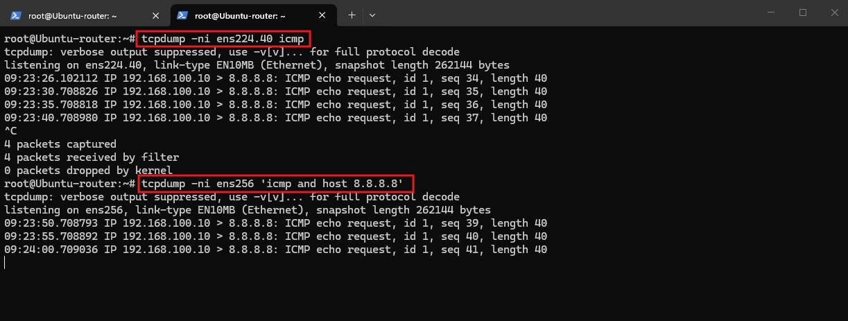
Using tcpdump, we can verify that ICMP packets from our TenantA VM (192.168.100.10 running a continous ping to 8.8.8.8) arrive on the Ubuntu router through the VLAN 40 interface (ens224.40) and are subsequently forwarded through the WAN interface (ens256) toward 8.8.8.8.
Both captures show the original source address
192.168.100.10, confirming that routing and IP forwarding are working correctly, but Source Network Address Translation (SNAT) is not yet configured. Without SNAT, the FritzBox cannot return the responses to our isolated tenant network because it has no corresponding route.
tcpdump -ni ens224.40 icmp
tcpdump -ni ens256 'icmp and host 8.8.8.8'
For more information about capturing and analyzing network traffic with tcpdump, refer to my dedicated article
Configure Tenant-Specific Routing and NAT
Now that we’ve verified that TenantA traffic reaches the WAN interface, we can configure the remaining components required for Internet connectivity while maintaining isolation between tenants.
Since TenantA and TenantB will eventually use the same 192.168.100.0/24 subnet, we combine Linux VRFs, Netfilter connection marking, policy routing, and Source Network Address Translation (SNAT).
VRFs and policy routing provide tenant-specific forwarding, while SNAT translates outbound traffic to the Ubuntu router’s WAN address (192.168.178.48), allowing responses to return through the FritzBox.
We begin by configuring persistent nftables connection marking, followed by tenant-specific policy routing and Source NAT.
Configure Tenant-Specific Connection Tracking
Before configuring Source NAT (SNAT), we need to account for TenantA and TenantB using the same 192.168.100.0/24 subnet.
As demonstrated in our Hyper-V Network Virtualization (HNV) setup, we can combine Linux VRFs, Netfilter connection marks (ct mark), and policy routing (fwmark) to identify tenant traffic and direct returning packets through the appropriate tenant routing table.
For TenantA, we use connection mark 1001 and routing table 1001. TenantB will later use 1002 for both.
We define the corresponding nftables configuration persistently in /etc/nftables.conf.
nano /etc/nftables.conf
Use the following configuration, assuming nftables is not already managing other firewall rules:
#!/usr/sbin/nft -f

flush ruleset

table ip nat {
    chain postrouting {
        type nat hook postrouting priority srcnat; policy accept;
    }
}

table ip tenant_routing {
    chain prerouting {
        type filter hook prerouting priority mangle; policy accept;

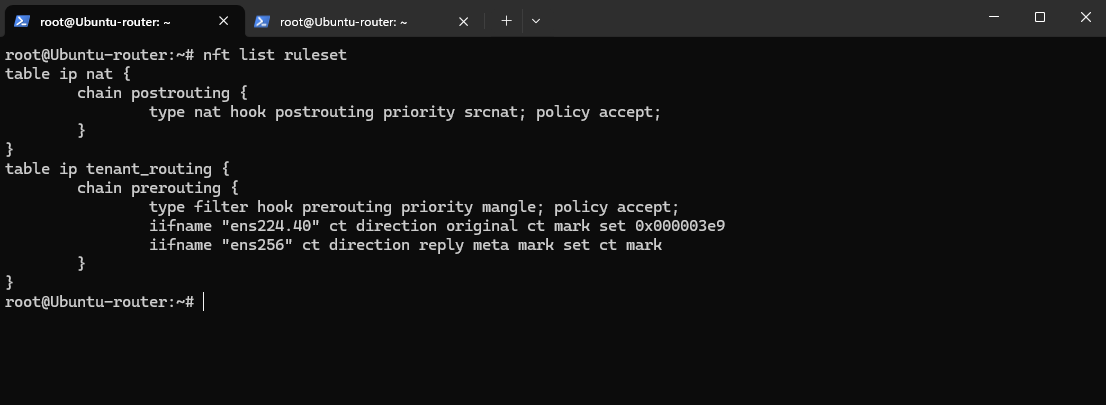
        iifname "ens224.40" ct direction original ct mark set 1001
        iifname "ens256" ct direction reply meta mark set ct mark
    }
}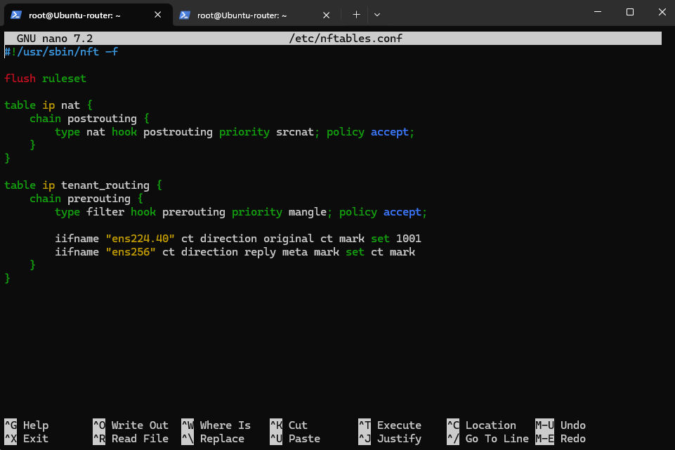
The nat table prepares source NAT, while tenant_tracking assigns incoming TenantA traffic to connection tracking zone 1001. No actual SNAT rule has been configured yet.
Validate and load the configuration:
nft -c -f /etc/nftables.conf
systemctl enable --now nftables
nft -f /etc/nftables.conf

Verify:
By storing our nftables configuration in
/etc/nftables.confand enabling the nftables systemd service, the rules are automatically restored after a reboot. This provides a persistent foundation for tenant-specific connection tracking and NAT, which we will extend to support overlapping tenant networks.
nft list ruleset
The current policy-routing configuration contains only the default Linux rules and the l3mdev rule used for VRF routing.
We will extend it with a tenant-specific firewall mark (
fwmark) rule so that returning traffic can be directed to the appropriate tenant routing table.
ip -4 rule show

Configure Persistent Policy Routing for TenantA
With connection marking configured in nftables, we can now extend Linux policy routing to direct returning packets into the appropriate tenant routing table.
For TenantA, packets marked with 1001 should use routing table 1001, which contains the return route to 192.168.100.0/24 through the NSX Tier-0 VRF gateway (10.0.40.2).
To make this configuration persistent, we extend our existing /etc/netplan/60-nsx-vrf.yaml file:
network:
  version: 2
  ethernets:
    ens224:
      dhcp4: false

  vlans:
    ens224.40:
      id: 40
      link: ens224
      addresses:
        - 10.0.40.1/30
      routes:
        - to: 192.168.100.0/24
          via: 10.0.40.2
      routing-policy:
        - from: 0.0.0.0/0
          mark: 1001
          table: 1001
          priority: 500

  vrfs:
    vrf-tenantA:
      table: 1001
      interfaces:
        - ens224.40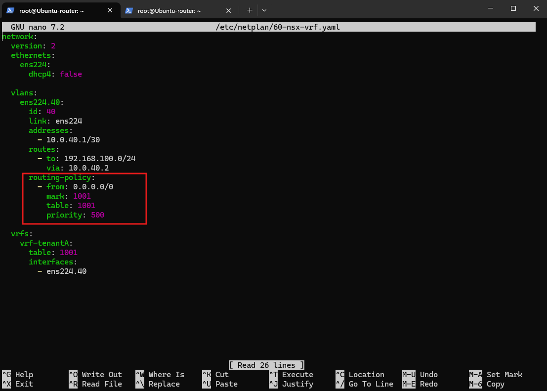
Validate and apply:
netplan generate
netplan apply
Then verify:
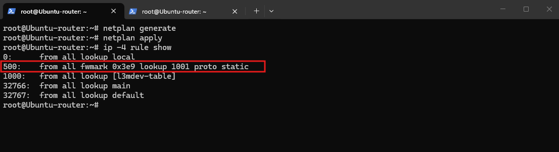
The output confirms that packets marked with
1001(0x3e9in hexadecimal) are directed to TenantA’s routing table1001.With priority
500, this rule is evaluated before the default VRF rule (l3mdev) at priority1000, allowing marked return traffic to use TenantA’s routing table.
ip -4 rule show
Configure Source NAT for TenantA
With tenant-specific connection marking and policy routing now configured, we can implement Source Network Address Translation (SNAT) to provide Internet access for our TenantA workloads.
Using nftables masquerading, we translate outgoing tenant traffic to the Ubuntu router’s WAN IP address (192.168.178.48) before forwarding it to the FritzBox (192.168.178.1). This allows Internet hosts to send responses back to our Ubuntu router, where connection tracking and policy routing can direct them toward the appropriate tenant network.
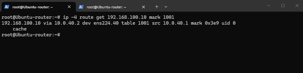
The ip -4 route get command confirms that packets marked with firewall mark 1001 are routed through TenantA’s dedicated routing table 1001.
Traffic destined for
192.168.100.10is forwarded via the NSX Tier-0 VRF gateway (10.0.40.2) using VLAN interfaceens224.40, verifying that the policy-routing lookup selects the correct return path.
ip -4 route get 192.168.100.10 mark 1001
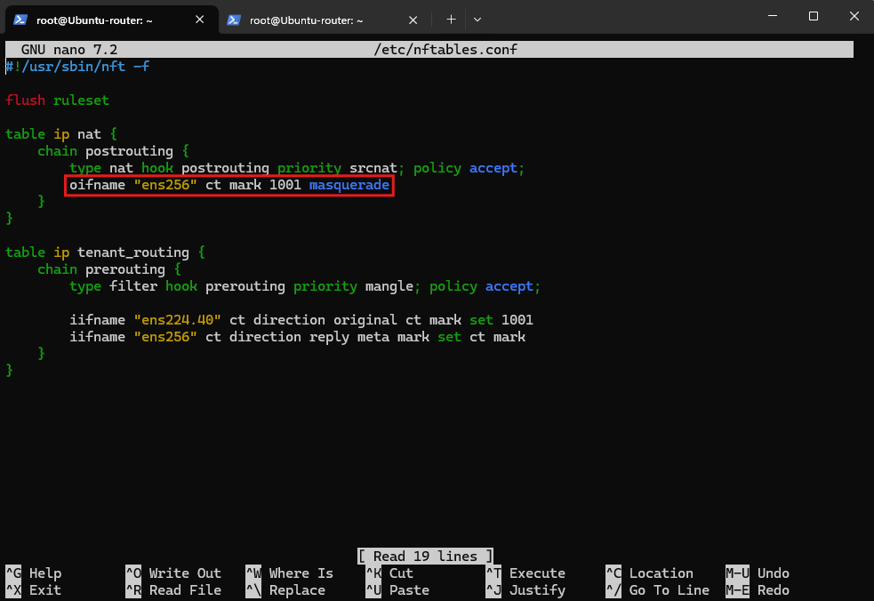
Now we can add the actual SNAT masquerading rule to our persistent nftables configuration.
In /etc/nftables.conf, add the following rule inside the existing postrouting chain:
oifname "ens256" ct mark 1001 masquerade
Validate the persistent configuration first:
nft -c -f /etc/nftables.conf
If validation succeeds, apply it:
nft -f /etc/nftables.conf

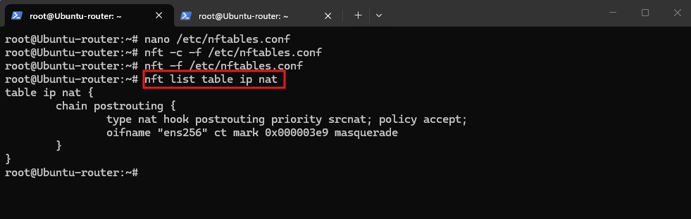
Then verify:
The output confirms that our persistent nftables configuration now includes the Source NAT masquerading rule for TenantA.
Outbound traffic marked
1001is translated to the Ubuntu router’s WAN address (192.168.178.48) before being forwarded to the FritzBox.
nft list table ip nat
Verify TenantA Internet Connectivity
With Source NAT configured, we can now verify whether our TenantA workloads can access the Internet through the NSX Tier-1 and Tier-0 gateways, the Ubuntu router, and finally the FritzBox.
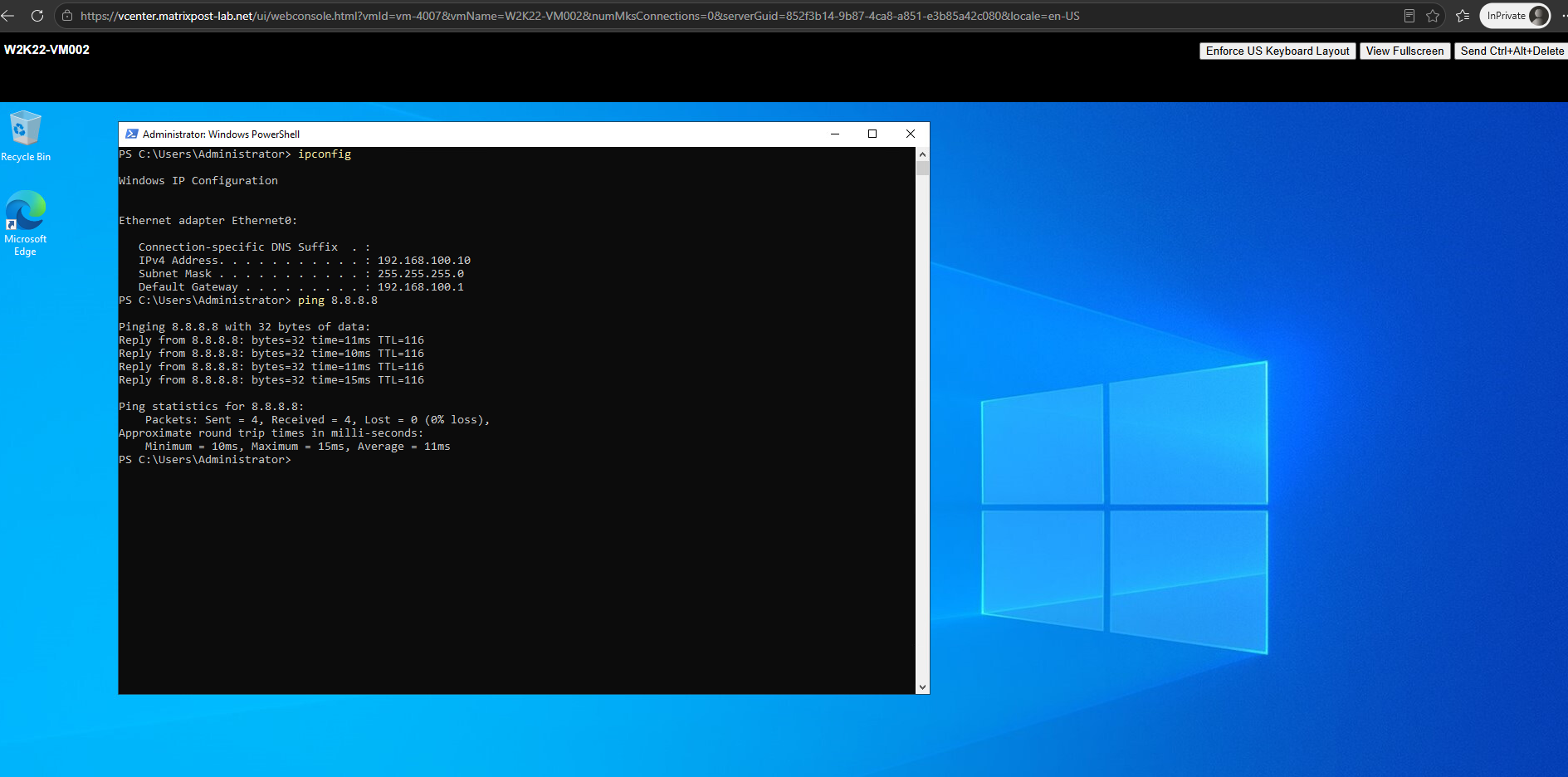
We first send ICMP echo requests from our TenantA Windows VM (192.168.100.10) to Google’s public DNS server (8.8.8.8).
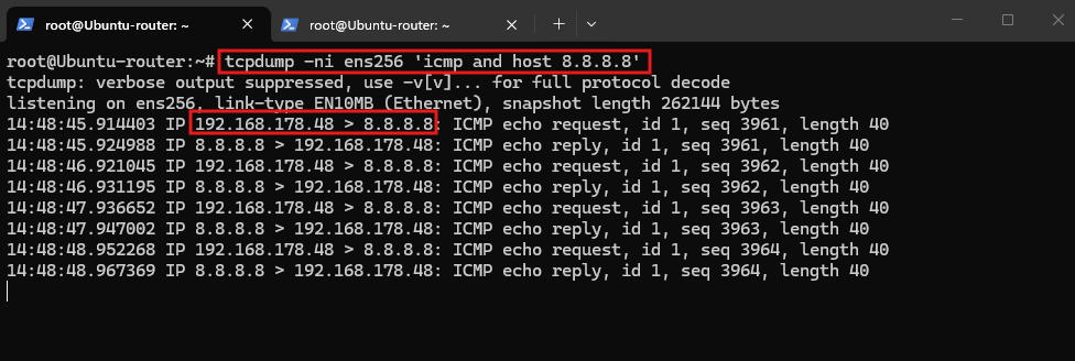
At the same time, we capture the traffic on the Ubuntu router’s WAN interface (ens256) to verify that Source NAT translates the original tenant IP address to 192.168.178.48.
On the Windows VM:
The final connectivity test confirms that our TenantA workload can successfully access the Internet through the NSX overlay network, Tier-1 and Tier-0 gateways, and Ubuntu router.
All four ICMP requests received replies, with 0% packet loss, confirming that routing, Source NAT, and return traffic forwarding are working correctly.
ping 8.8.8.8
On the Ubuntu router:
The packet capture confirms that Source NAT is now working correctly. ICMP requests originating from our TenantA workload (
192.168.100.10) leave the Ubuntu router throughens256using its WAN address (192.168.178.48), and the corresponding replies from8.8.8.8successfully return.
tcpdump -ni ens256 'icmp and host 8.8.8.8'
Since the ICMP connection was already tracked before we enabled masquerading, we first had to delete the existing connection-tracking entry to allow the new NAT rule to take effect.
conntrack -D -f ipv4 -p icmp --orig-src 192.168.100.10 --orig-dst 8.8.8.8
Links
Network Connection Status Indicator (NCSI) troubleshooting guidance
https://learn.microsoft.com/en-us/troubleshoot/windows-server/networking/troubleshoot-ncsi-guidanceNSX-T Data Center Administration Guide
https://www.sapientcode.com/static/images/NSX/nsxt_31_admin.pdf