Microsoft Hyper-V Networking Best Practices – Part 1 – Installing Hyper-V and Preparing the Lab Environment
Hyper-V has become a mature enterprise virtualization platform that provides high availability, live migration, software-defined networking, and deep integration with the Microsoft ecosystem. Whether deployed in small environments or large datacenters, a well-designed network architecture is essential for building a reliable, secure, and high-performing Hyper-V infrastructure.
In this article series, we will explore Microsoft’s recommended networking best practices for Hyper-V by designing and building a production-ready environment from the ground up. Instead of simply walking through the configuration steps, I will explain the reasoning behind each design decision and discuss the best practices commonly used in enterprise environments.
For all demonstrations throughout this series, I will use a two-node Hyper-V Failover Cluster running Windows Server 2025. The environment will be configured according to current Microsoft recommendations and will serve as the foundation for topics such as Hyper-V virtual switches, Switch Embedded Teaming (SET), Live Migration, Cluster Shared Volumes (CSV), VLANs, SMB Multichannel, RDMA, Quality of Service (QoS), management networking, and many other networking concepts required for a modern Hyper-V deployment.
Although the demonstrations are based on Windows Server 2025, the majority of the concepts and best practices presented in this series also apply to earlier and future versions of Hyper-V unless explicitly stated otherwise.
In this first part of the series, we prepare the complete Hyper-V lab environment that will be used throughout the remaining articles. We start by installing the Hyper-V role, create a temporary external virtual switch, deploy the initial virtual machines, install Active Directory Domain Services (AD DS), and configure the first domain controller as well as a pfSense firewall appliance.
Once the lab infrastructure is in place, the following parts of the series will focus on designing and implementing the final Hyper-V networking according to Microsoft’s best practices, followed by the configuration of Switch Embedded Teaming (SET) and Failover Clustering.
In Part 2, we will configure the final Hyper-V networking according to Microsoft best practices, including Switch Embedded Teaming (SET), redundant management and VM networks, and finally create our two-node Hyper-V Failover Cluster.
In Part 3, we will extend the cluster with shared iSCSI storage, configure a Cluster Shared Volume (CSV), migrate our existing virtual machines to shared storage, make them highly available clustered VMs, and test Live Migration and automatic failover.
In Part 4, we will deploy and explore System Center Virtual Machine Manager (SCVMM) for centralized management of our Hyper-V environment and compare its architecture, features, and management experience with VMware vCenter.
Install the Hyper-V Server Role
Before we can create and manage virtual machines, we first need to install the Hyper-V server role on each Windows Server that will become part of our Hyper-V cluster. We can install the role by using the Add Roles and Features Wizard in Server Manager or by using PowerShell. In this series, I will demonstrate both approaches where appropriate.
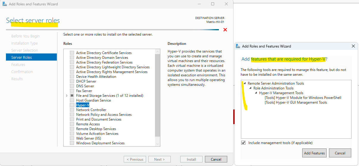
Select the Hyper-V server role in the Add Roles and Features Wizard. When prompted, click Add Features to install the required Hyper-V management tools, including the Hyper-V Module for Windows PowerShell and the Hyper-V GUI Management Tools, as shown below.
For a 2-node Windows Server 2025 Hyper-V cluster, I’d recommend something like this:
A Top-of-Rack (ToR) switch is a network device mounted in the upper section of a server rack. It connects local servers using short cables to reduce latency and simplify data center cabling, compared to running long cables to a central End-of-Row (EoR) switch.
| NIC | Purpose | Connected to |
|---|---|---|
| NIC 1 | Management | ToR Switch A |
| NIC 2 | Management | ToR Switch B |
| NIC 3 | Hyper-V Virtual Switch / VM Traffic | ToR Switch A |
| NIC 4 | Hyper-V Virtual Switch / VM Traffic | ToR Switch B |
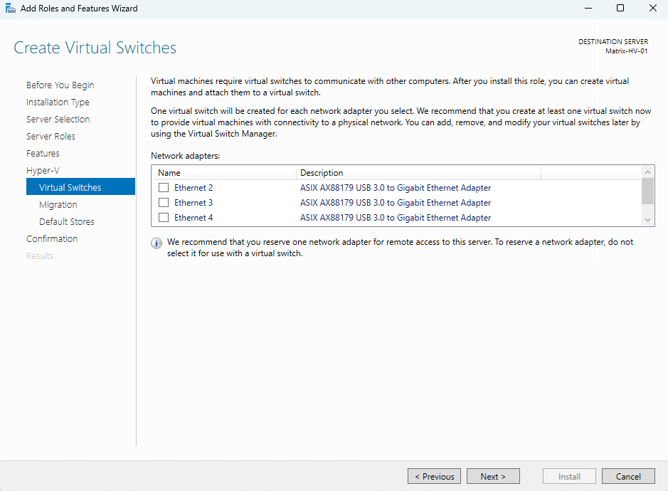
Skip the “Create Virtual Switches” page below by clicking Next. We will configure the Hyper-V virtual switches later in this series according to Microsoft’s networking best practices by using Switch Embedded Teaming (SET).
Note: For this lab environment, I am using two Dell XPS 15 notebooks as Hyper-V hosts. Similar to my VMware vSphere lab, I extended the built-in network connectivity by using multiple ASIX AX88179 USB 3.0 Gigabit Ethernet adapters.
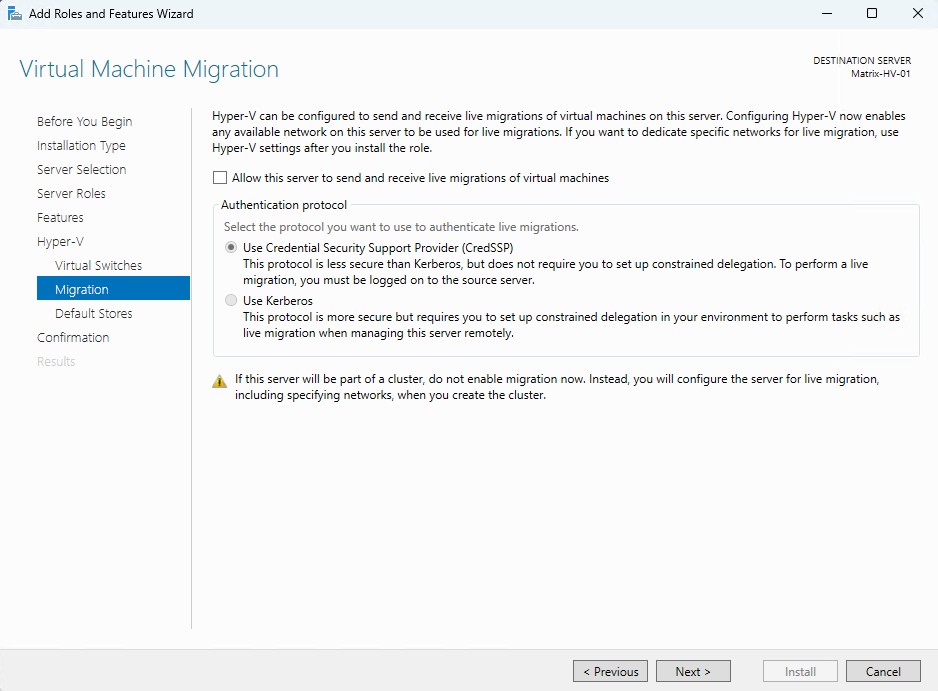
This page allows you to configure Live Migration for standalone Hyper-V hosts. Because we are building a Hyper-V Failover Cluster, leave this option disabled.
We will configure Live Migration later during the cluster configuration, where we can also specify the dedicated migration networks and authentication settings.
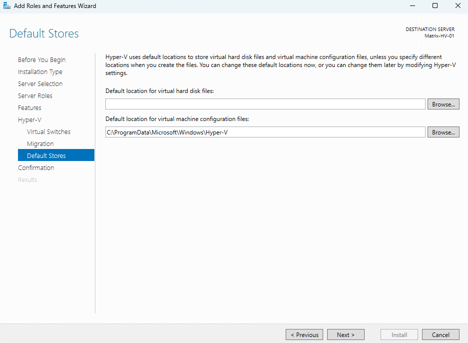
This page allows you to configure the default storage locations for virtual hard disks (VHD/VHDX) and virtual machine configuration files.
Because this server will become part of a Hyper-V Failover Cluster, leave the default settings unchanged. Once the cluster and Cluster Shared Volumes (CSV) have been configured, we will move the default storage locations to the shared cluster storage according to Microsoft’s best practices.
Review the installation summary and verify that the Hyper-V role and the required management tools are selected.
Optionally, enable Restart the destination server automatically if required to allow Windows to reboot automatically after the installation. Finally, click Install to begin the installation.
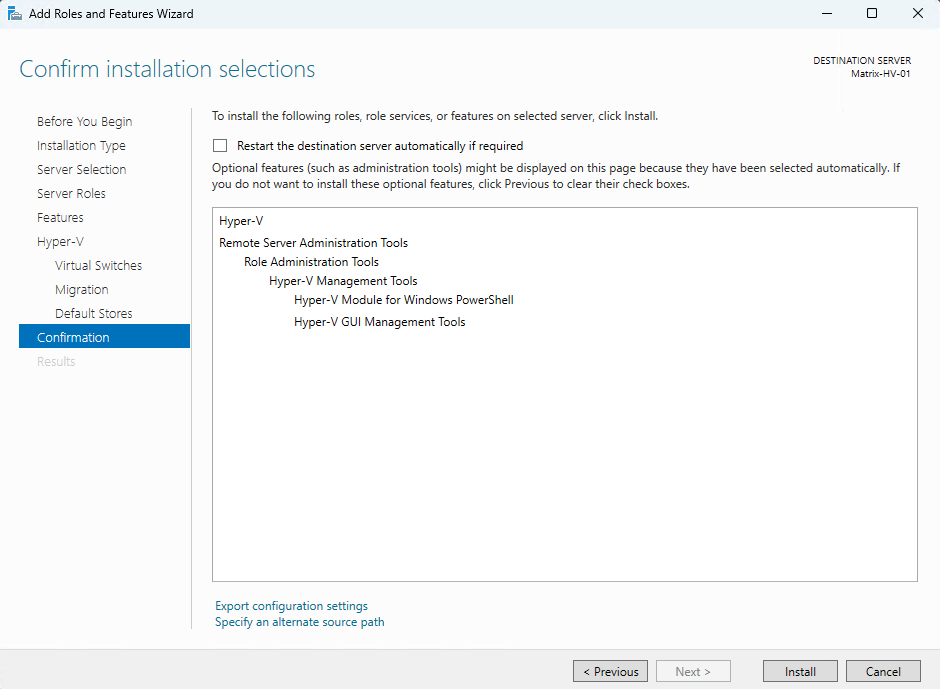
The Hyper-V role is now being installed on our first Hyper-V host, Matrix-HV-01. After the installation has completed successfully, repeat the same procedure on the second Hyper-V host, Matrix-HV-02, to ensure both hosts are configured identically before proceeding with the Failover Cluster configuration.
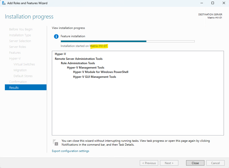
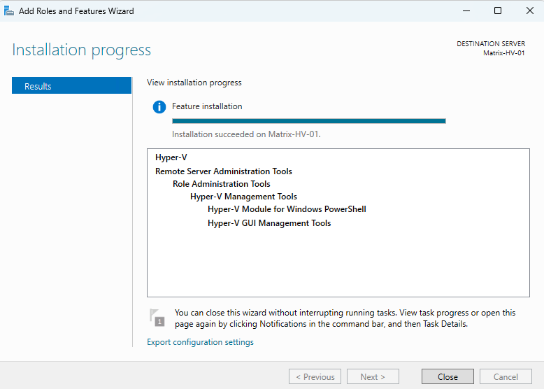
The installation completed successfully on Matrix-HV-01, and the server was automatically restarted to finalize the installation. Next, install the Hyper-V role on Matrix-HV-02 using the same procedure so that both hosts have an identical configuration before creating the Failover Cluster.
Install the Hyper-V Role by Using PowerShell
Instead of using the Add Roles and Features Wizard, you can also install the Hyper-V role and the required management tools by using PowerShell:
The
-IncludeManagementToolsparameter installs the Hyper-V management tools, including Hyper-V Manager and the Hyper-V PowerShell module, while the-Restartparameter automatically restarts the server if required to complete the installation.Repeat the command on both Hyper-V hosts (Matrix-HV-01 and Matrix-HV-02) before proceeding with the Failover Cluster configuration.
PS> Install-WindowsFeature -Name Hyper-V -IncludeManagementTools -Restart
Prepare the Hyper-V Lab Environment
Before we continue with configuring the Hyper-V networking and creating the Failover Cluster, we first need to prepare the lab environment.
A Hyper-V Failover Cluster requires a working Active Directory Domain Services (AD DS) and DNS infrastructure. Therefore, we will first deploy a virtual machine running Windows Server 2025, promote it to a domain controller, and configure it as the DNS server for our lab environment.
Once Active Directory is available, we will join both Hyper-V hosts (Matrix-HV-01 and Matrix-HV-02) to the domain before proceeding with the remaining cluster configuration.
To create a realistic enterprise lab, we will also deploy a pfSense virtual appliance, which will act as the lab’s gateway, firewall, and router. Besides providing Internet access for the virtual machines, pfSense will also enable us to demonstrate additional networking scenarios throughout this series.
The deployment and configuration of Active Directory, DNS, and pfSense are outside the scope of this series, as the focus is on Hyper-V networking. ´
Nevertheless, below we will walk through the deployment of both the Domain Controller and the pfSense virtual machines, including their virtual hardware and networking configuration.
Only the operating system and service configuration inside Windows Server and pfSense is intentionally omitted.
If you are interested in building a similar lab environment, about how to download and setup pfSense you will find here and also you will find many other infrastructure components throughout my blog.
Creating the Temporary Virtual Switch
Before configuring the final Hyper-V networking according to Microsoft’s best practices, we first need a temporary external virtual switch to deploy the initial virtual machines, such as the domain controller and the pfSense appliance.
In my lab environment, the USB network adapters #5 and #7 are connected to 802.1Q trunk ports on the physical switches and will later be used for the production Hyper-V networking. The adapters #no-number and #6 are connected to access ports assigned to VLAN 10, which will later serve as the management network.
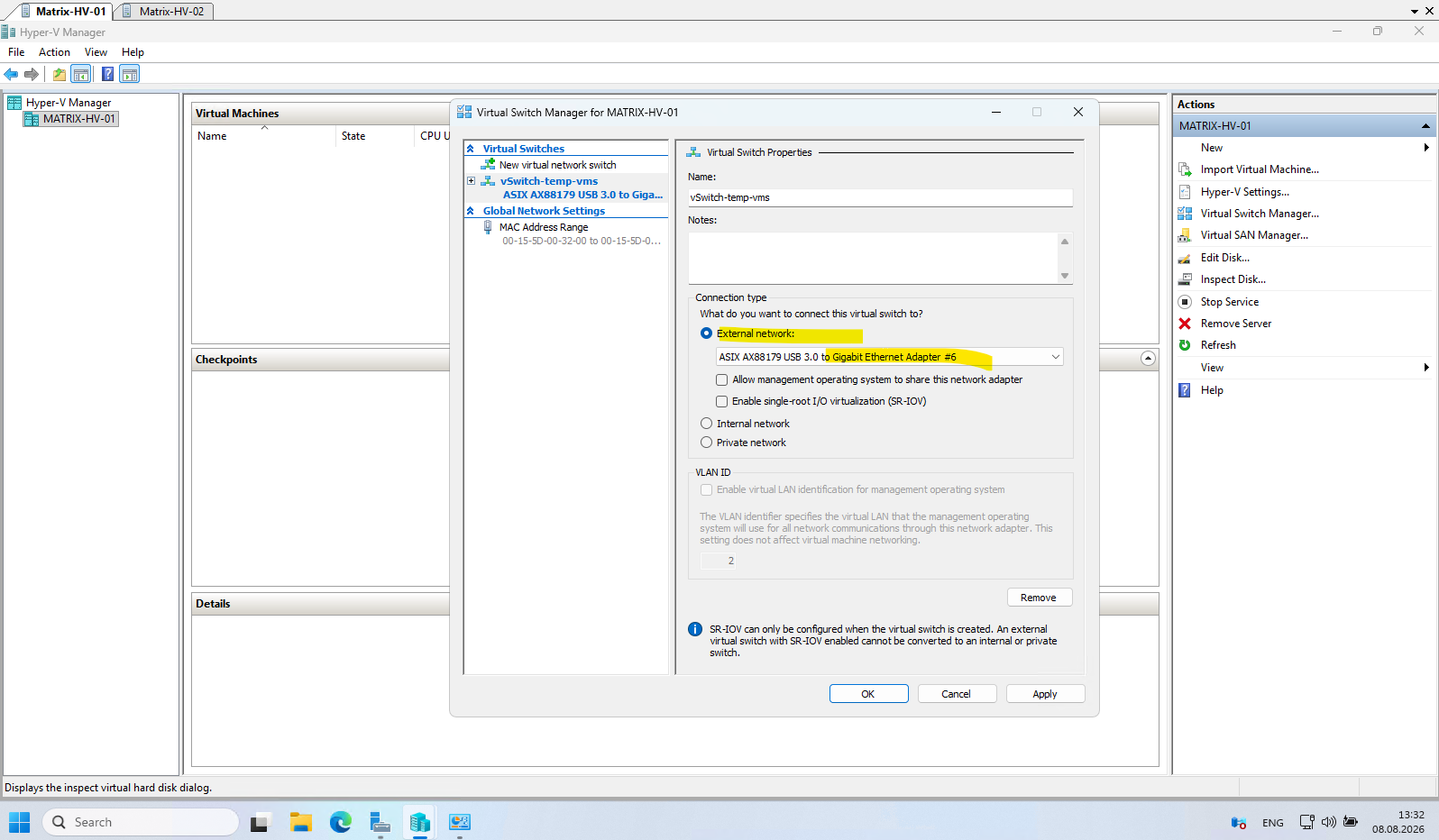
To provide temporary network connectivity for the initial virtual machines, I will therefore create an External Virtual Switch by using adapter #5. Once the lab infrastructure has been deployed, this temporary configuration will be replaced by the final networking design described later in this series.
Note: Because adapter #5 is connected to an 802.1Q trunk port and is used by the temporary internal LAN virtual switch, each virtual machine connected to this switch must have VLAN ID 10 configured on its virtual network adapter. Unlike VMware vSphere, Hyper-V requires VLAN tagging to be configured individually for each virtual network adapter that is connected to a virtual switch backed by a physical trunk port.
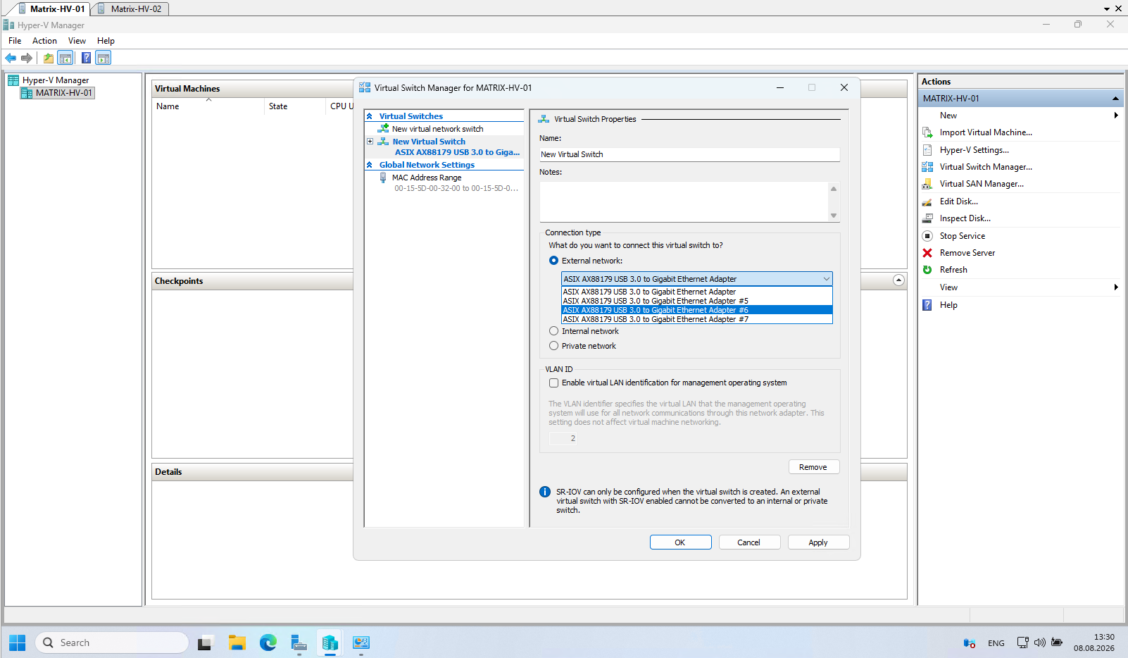
I will create a temporary External Virtual Switch by selecting network adapter #6. Since this adapter will be dedicated to the virtual machines, leave Allow management operating system to share this network adapter unchecked and click OK.
Creating the Domain Controller Virtual Machine
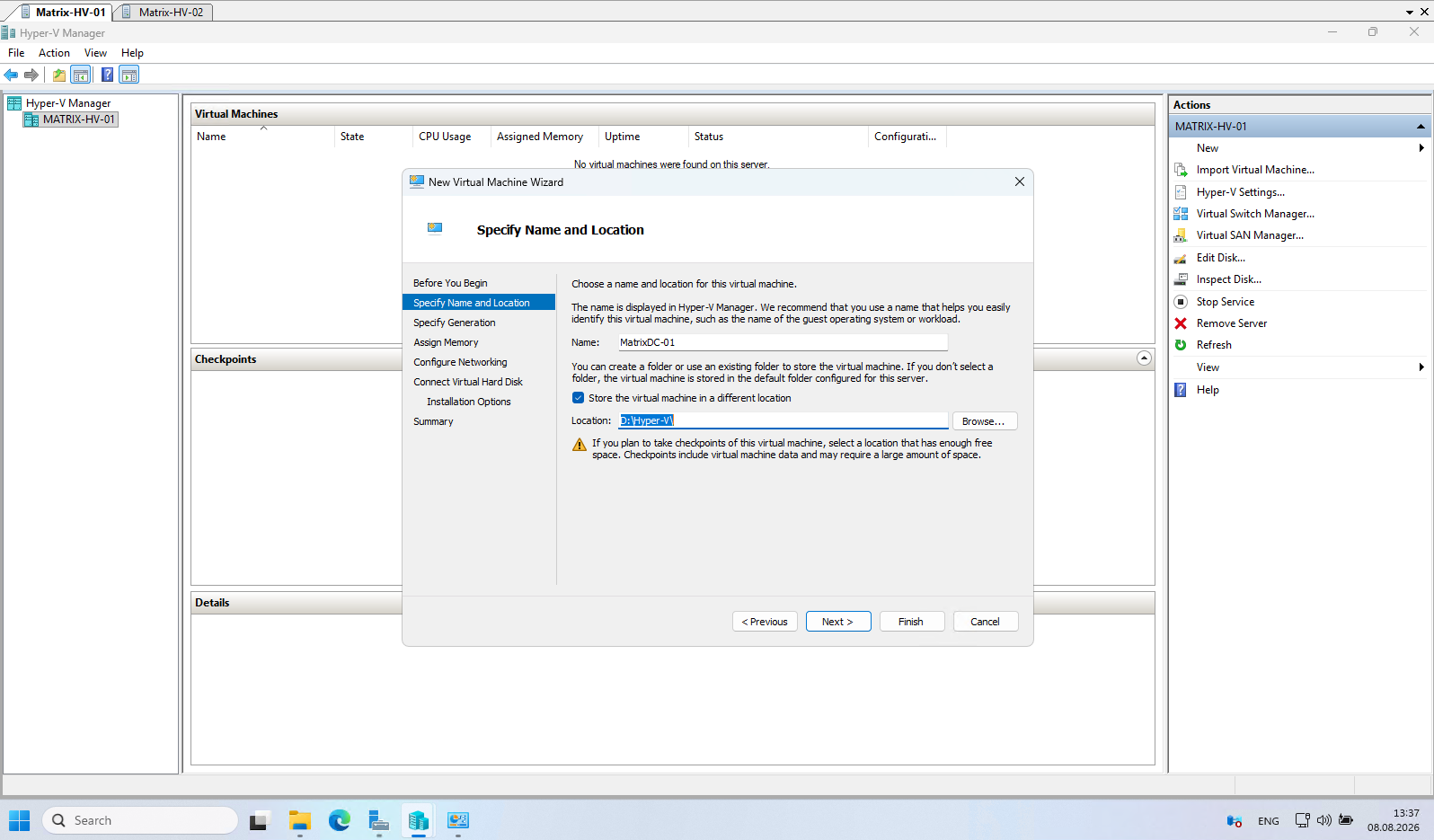
For the initial virtual machines, I will use the local D:\Hyper-V folder as a temporary storage location. Later in this series, after the Hyper-V Failover Cluster and Cluster Shared Volumes (CSV) have been configured, the virtual machines will be migrated to the shared cluster storage.
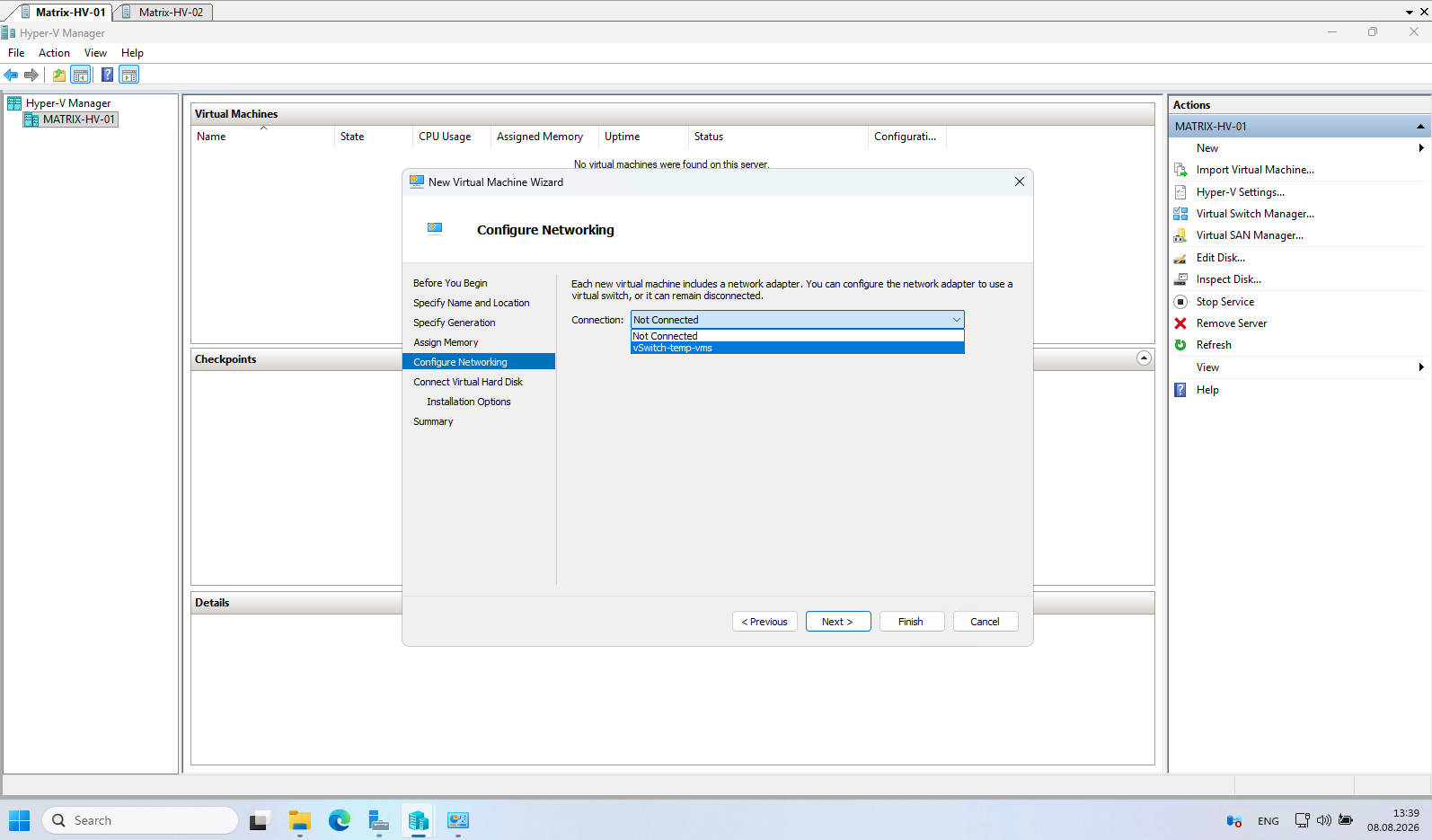
Connect the virtual machine to the temporary vSwitch-temp-vms virtual switch created earlier. This provides the virtual machine with network connectivity during the initial lab setup. Later in this series, the virtual machines will be migrated to the final Hyper-V networking configuration based on Switch Embedded Teaming (SET) and the production virtual switches.
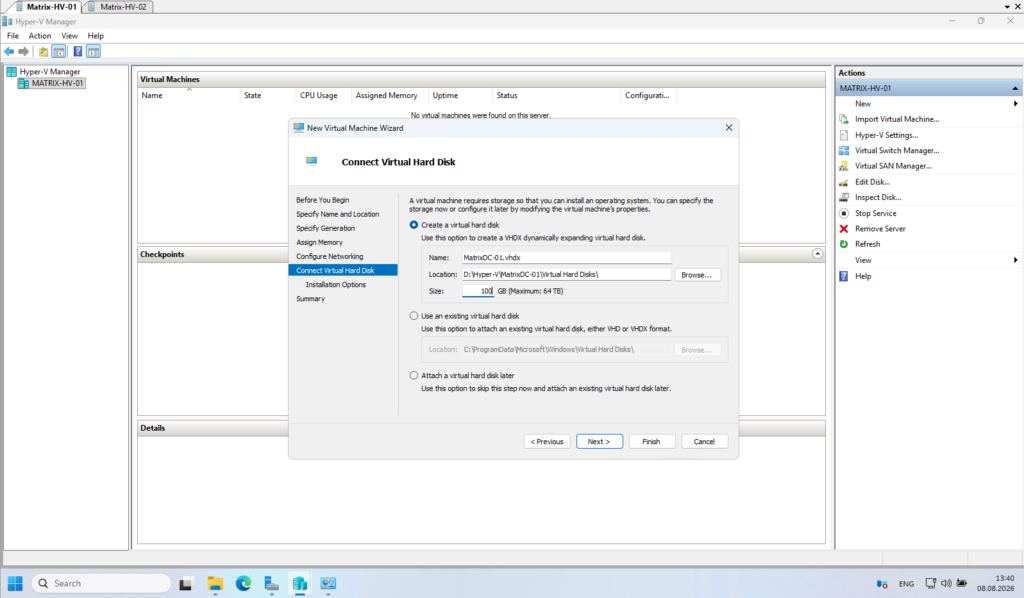
Create a new dynamically expanding VHDX virtual hard disk. For the initial Windows Server 2025 virtual machine, I will use a 100 GB virtual disk, which is sufficient for the domain controller in this lab environment.
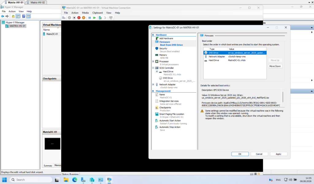
In Hyper-V, the boot order can be configured under Firmware in the virtual machine settings.
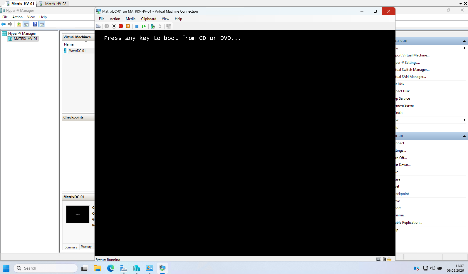
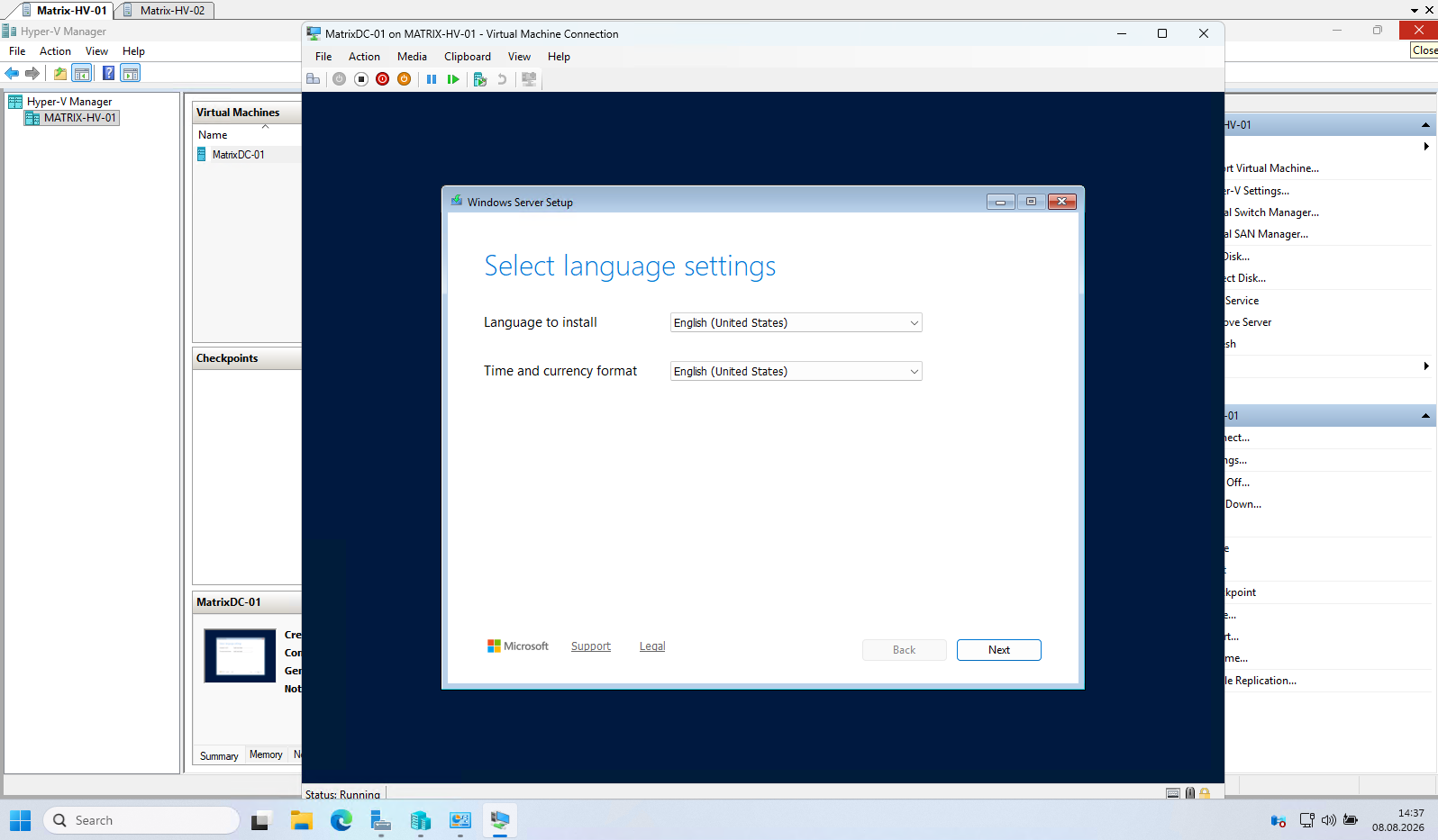
Ensure that the DVD Drive containing the Windows Server 2025 installation ISO is listed first so that the virtual machine boots directly into the Windows Setup.
I also have to configure the domain controller’s virtual network adapter to use VLAN ID 10, as the internal LAN operates in VLAN 10.
Note: Unlike VMware vSphere, Hyper-V does not associate VLAN IDs with the virtual switch. Instead, VLAN IDs are configured individually on each virtual machine’s network adapter (or optionally on the management OS adapter). This provides similar functionality but follows a different configuration model.
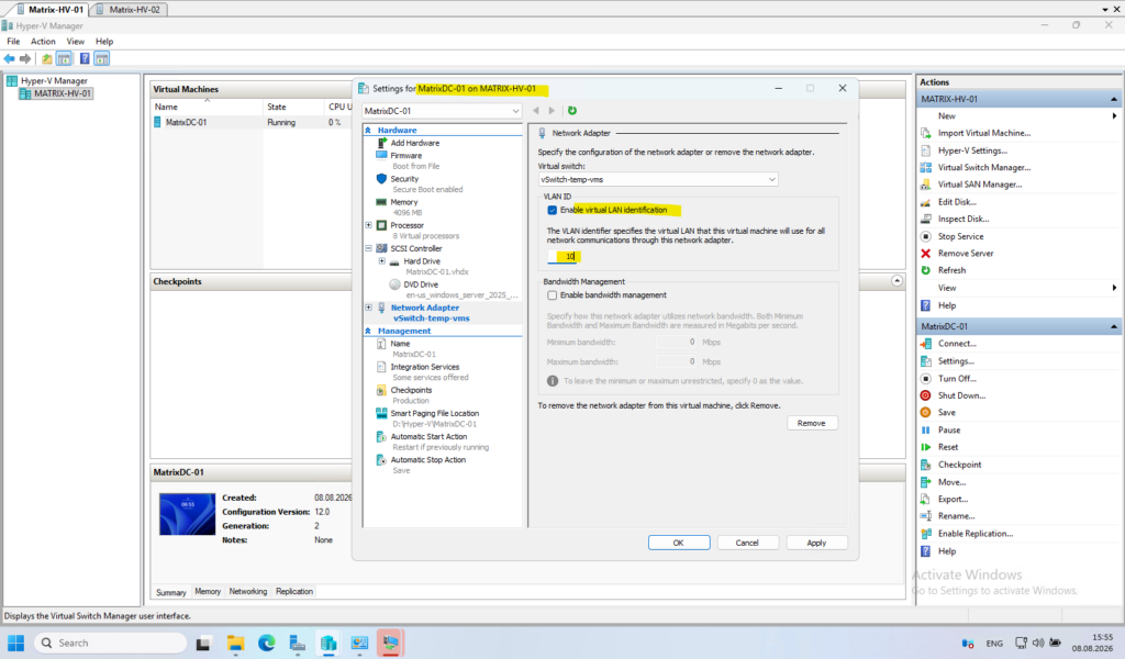
Instead of configuring the VLAN ID manually for each virtual machine, the following PowerShell command assigns VLAN 10 to all virtual network adapters connected to the vSwitch-LAN virtual switch. This is particularly useful when deploying multiple virtual machines.
Get-VMNetworkAdapter -VMName * |
    Where-Object SwitchName -eq "vSwitch-LAN" |
    Set-VMNetworkAdapterVlan -Access -VlanId 10
For a deeper understanding of VLANs, network segmentation, inter-VLAN routing, and VLAN ACLs, you can also refer to my following post.
Alternative: Dedicated Physical Networks Instead of VLANs
Design Note: VLANs provide a very flexible way to create multiple isolated Layer 2 network segments (aka broadcast domains) on shared physical network infrastructure. However, this flexibility also introduces additional configuration complexity, as VLAN IDs, access and trunk ports, tagging, and the corresponding virtual network configuration must be correctly configured and documented across the entire network path.
An alternative, particularly for smaller or less complex environments, is to use dedicated physical network adapters and physical switches for each network segment (IP subnet). Each Hyper-V network adapter is then connected to a dedicated physical network that carries only a single subnet, without requiring VLAN tagging. This approach is less flexible and requires more physical NICs, switch ports, cabling, and potentially additional switches, but it can make the overall network design considerably easier to understand, document, and troubleshoot.
Using dedicated physical networks also reduces the risk of configuration errors such as incorrect VLAN IDs, missing VLANs on trunk ports, or mismatched access/trunk configurations. On the other hand, adding another network segment generally requires additional physical infrastructure, whereas with VLANs another logical network can simply be added to the existing trunk infrastructure.
| VLAN-based segmentation | Dedicated physical networks |
|---|---|
| Multiple subnets over shared infrastructure | Separate physical infrastructure per subnet |
| Highly flexible and scalable | Simple and easy to understand |
| Fewer NICs, cables and switch ports | More NICs, cables and switch ports |
| Requires VLAN/trunk configuration | Little or no VLAN configuration |
| More configuration dependencies | Fewer configuration dependencies |
| Easier to add additional networks | New networks may require additional hardware |
| Troubleshooting can involve several VLAN layers | Physical network path is very obvious |
Creating the pfSense Virtual Appliance
For detailed instructions on downloading pfSense, refer to my following post.
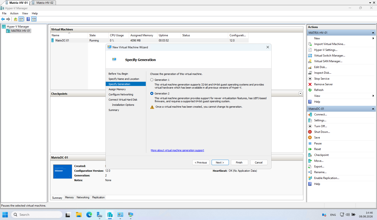
The current pfSense Plus 25.07 (2.8.1) as of today supports Generation 2 virtual machines in Hyper-V.
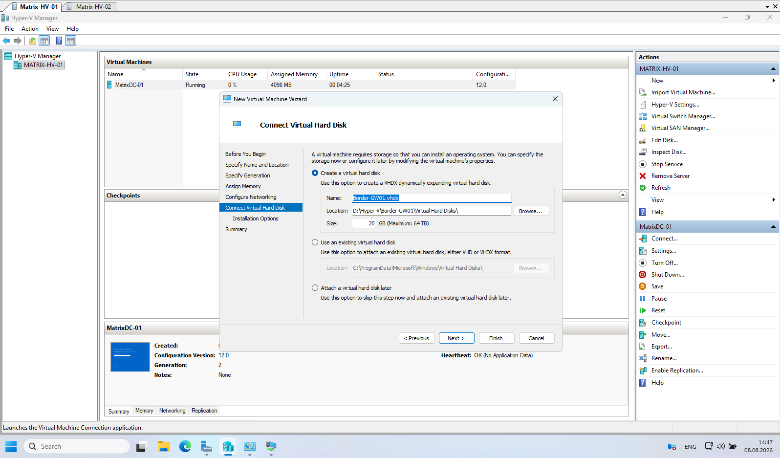
For the disk size are 16 GB or more recommended (minimum 8 GB, will install, but leaves little room for logs, updates, and packages).
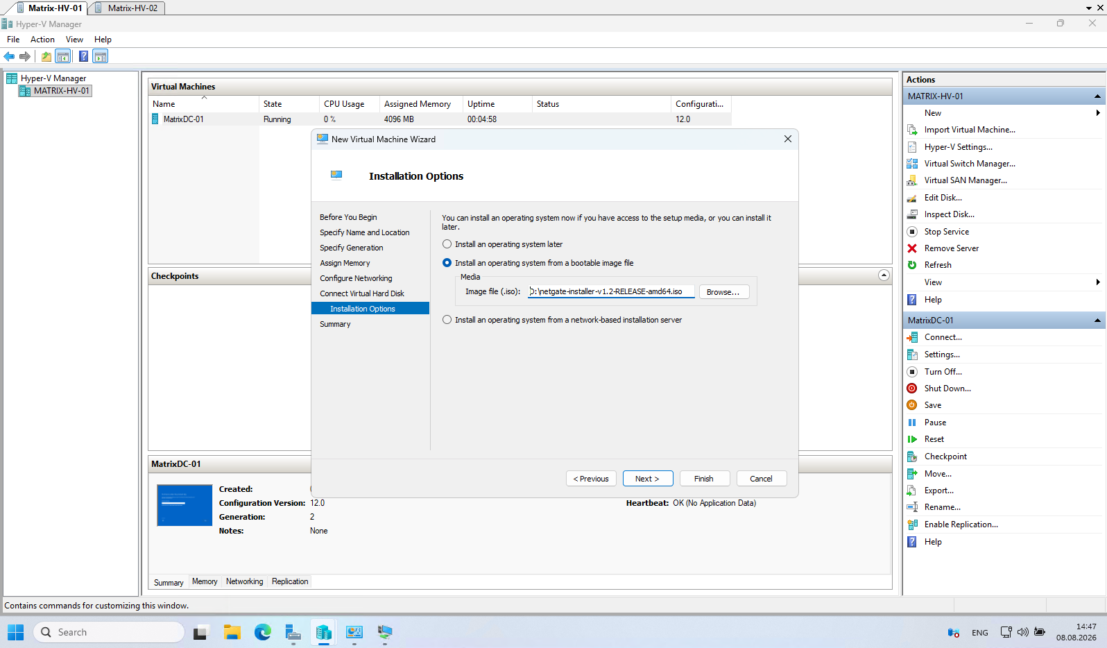
Select the pfSense ISO installer.
To deploy the pfSense virtual appliance as the lab’s border gateway and Internet firewall, no additional virtual switch is required.
The existing vSwitch-temp-vms is already connected to network adapter #5, which is connected to an 802.1Q trunk port on the physical switch. The trunk carries both VLAN 10 for the internal lab network and VLAN 100 for the WAN connection.
Therefore, both the LAN and WAN network adapters of the pfSense virtual machine can be connected to vSwitch-temp-vms, while the required VLANs (10 and 100) are configured on the individual virtual network adapters.
Since vSwitch-temp-vms is connected to a physical 802.1Q trunk port, configure the LAN network adapter of the pfSense virtual machine to use VLAN ID 10.
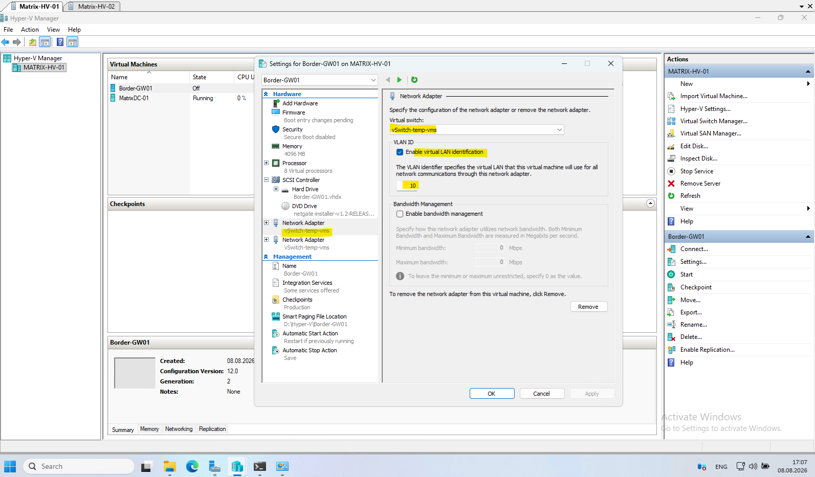
The WAN network adapter will be configured in the same way later, but with VLAN ID 100.
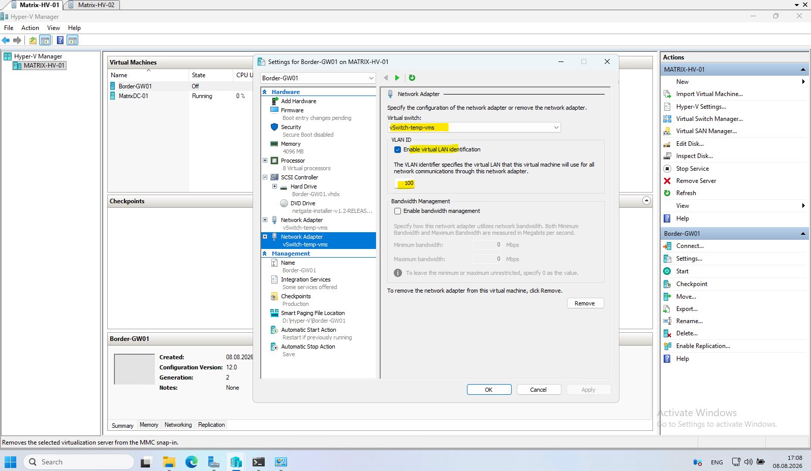
Note: Unlike VMware vSphere, Hyper-V does not associate VLAN IDs with the virtual switch. Instead, VLAN IDs are configured individually on each virtual machine’s network adapter (or optionally on the management OS adapter). This provides similar functionality but follows a different configuration model.
Later in Part 4, after deploying SCVMM, we will centralize and abstract this configuration using Logical Networks and VM Networks, making VLAN management across multiple Hyper-V hosts considerably easier and more comparable to networking in VMware vSphere.
As mentioned pfSense Plus 25.07 (2.8.1) supports Generation 2 virtual machines in Hyper-V.
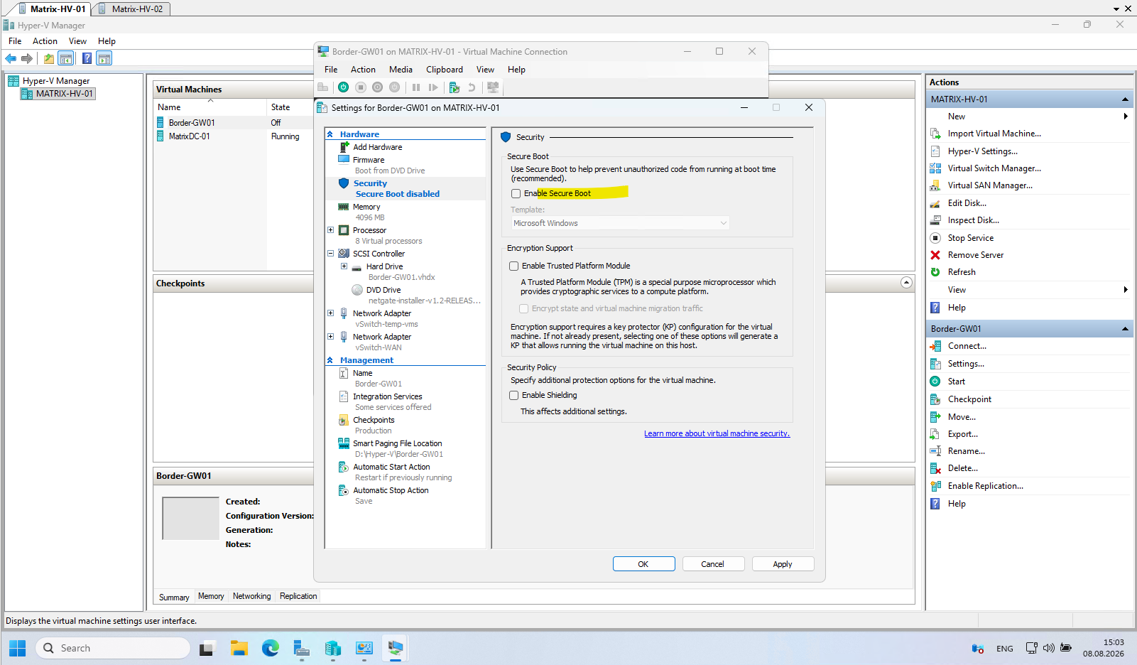
However, before booting from the installation ISO, you must disable Secure Boot in the virtual machine’s Security settings, as the pfSense boot loader is not signed with a Microsoft UEFI Secure Boot certificate.
Once Secure Boot has been disabled, the virtual machine will boot successfully from the pfSense installation media.
We can now power on the virtual machine to boot from the pfSense ISO installer.
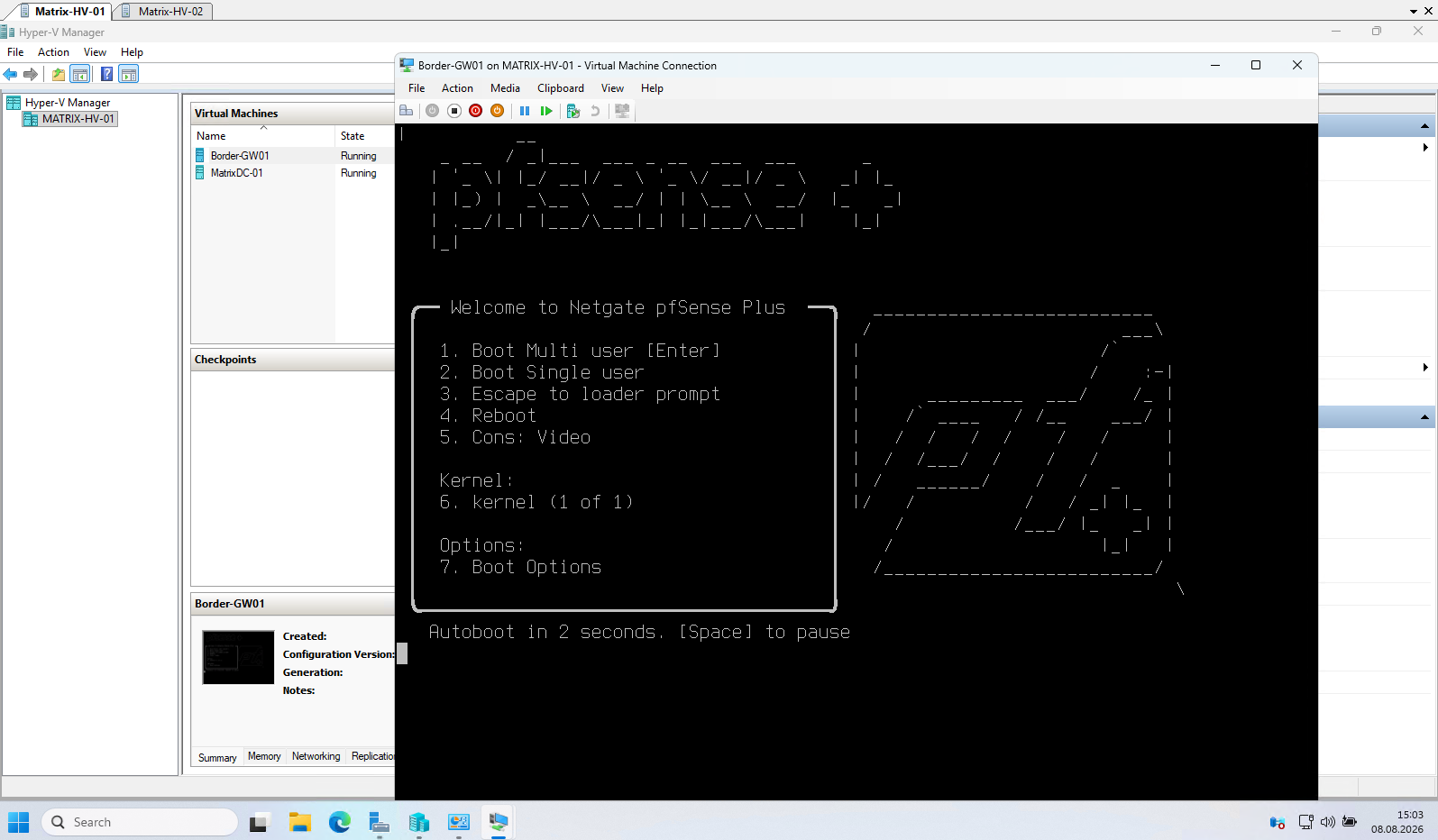
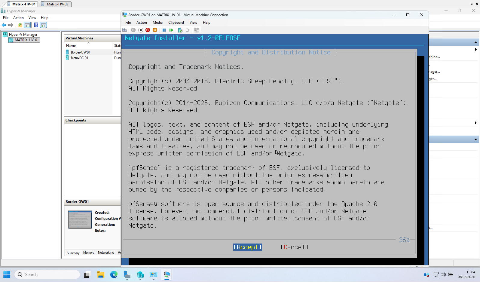
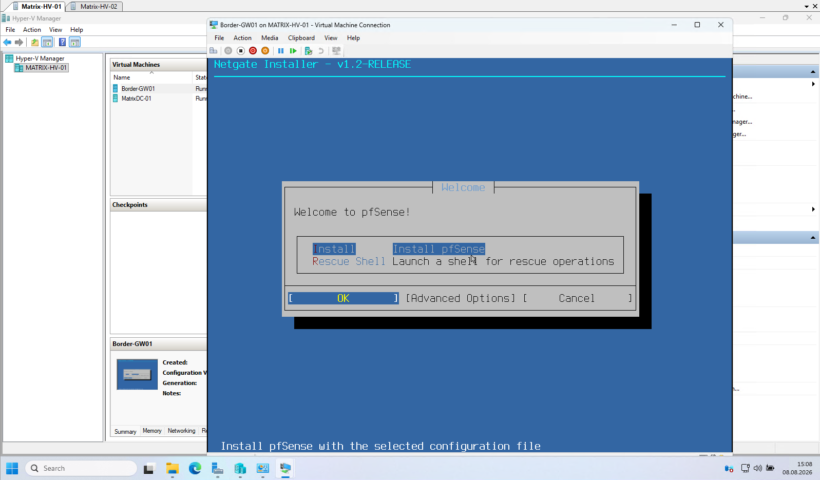
Select Install to start the pfSense installation using the default options. The default installation settings are sufficient for this lab environment and no advanced configuration is required.
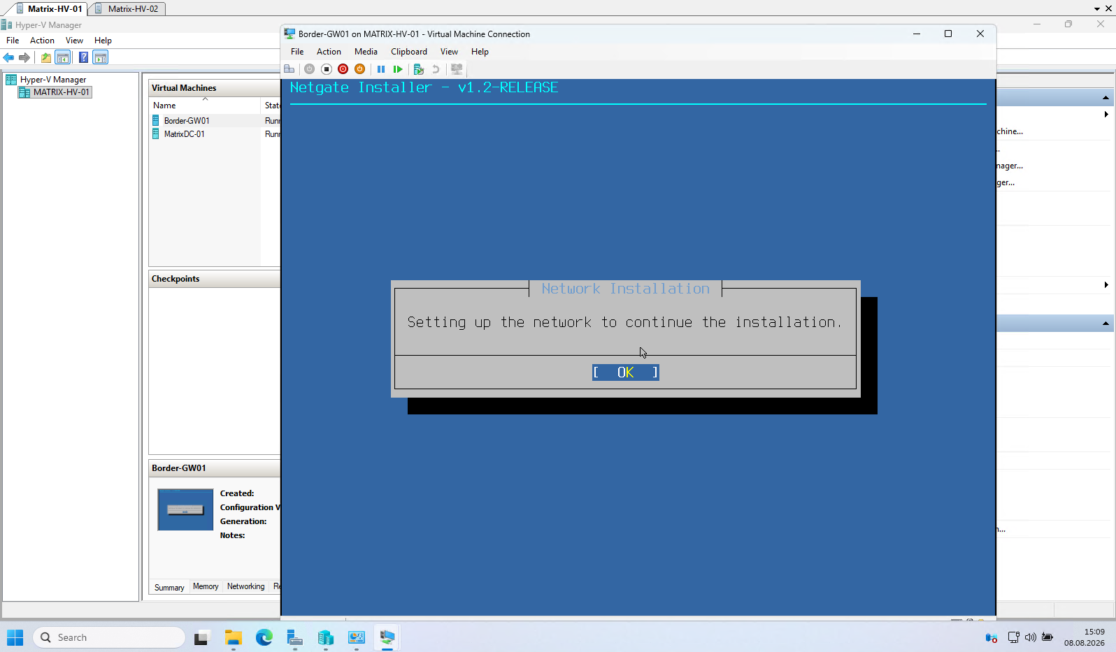
The pfSense installer identifies the virtual network adapters by their MAC addresses.
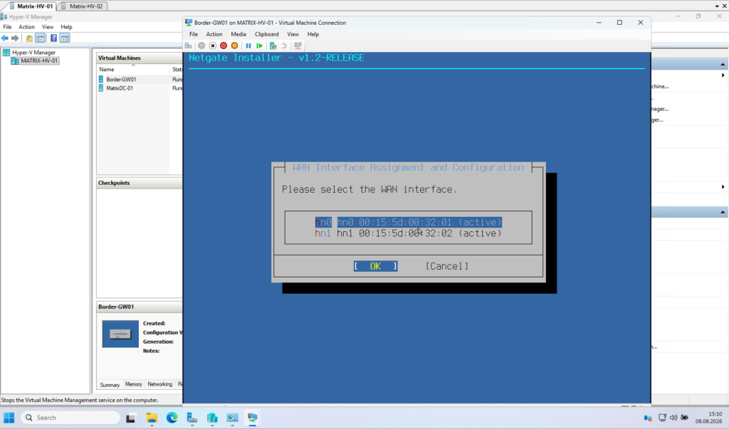
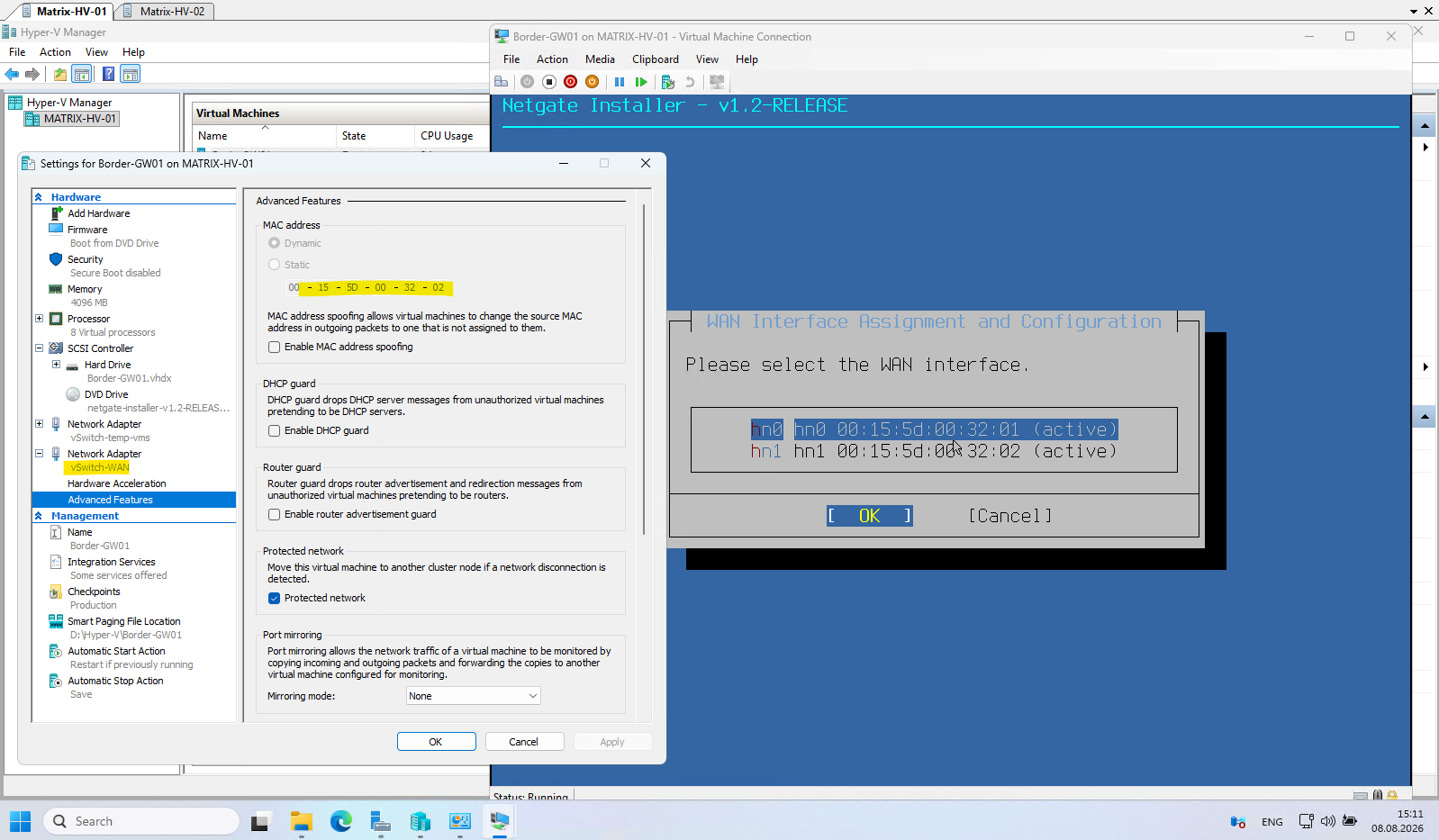
If you are unsure which interface is connected to the WAN or LAN virtual switch, compare the displayed MAC addresses with those shown in the Advanced Features of each Hyper-V network adapter.
Since the WAN interface is connected to my FRITZ!Box, it will automatically obtain its network configuration via DHCP. Therefore, the default DHCP (Client) mode is appropriate for this lab environment, and we can continue with the installation using the displayed settings.
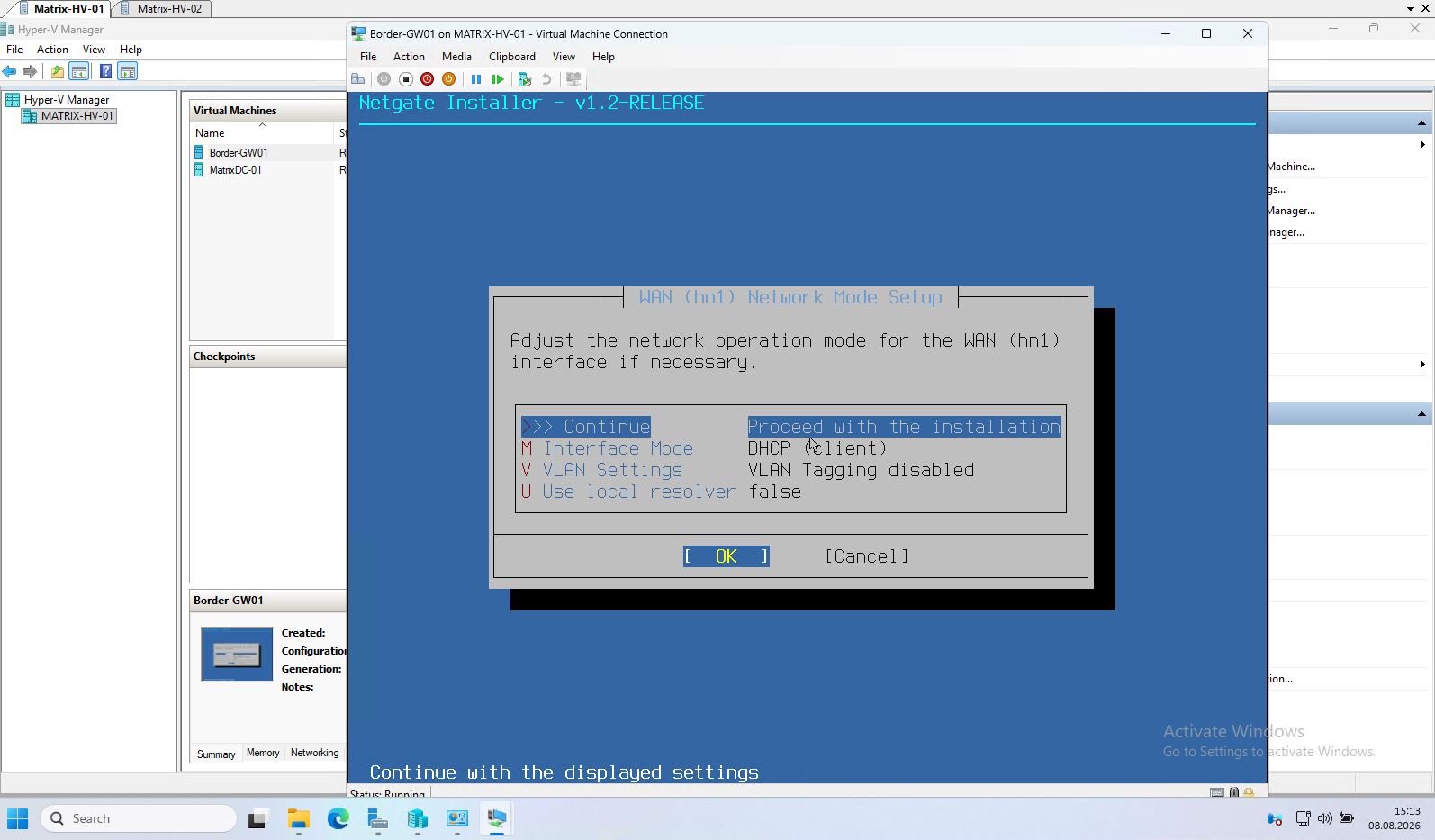
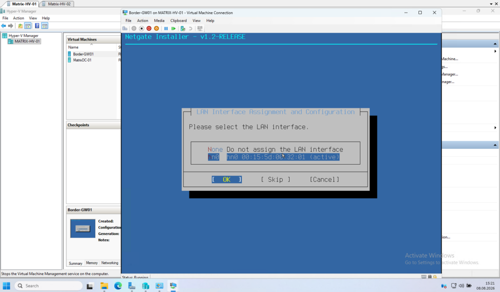
Finally, assign the remaining network interface to the LAN. This interface is connected to the temporary vSwitch-temp-vms virtual switch and will provide network connectivity for the internal lab environment.
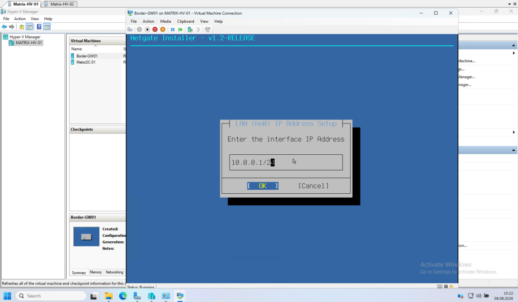
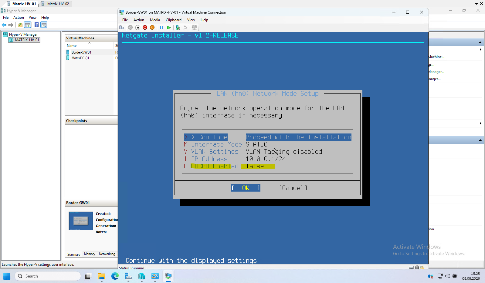
Configure the LAN interface with the static IP address 10.0.0.1/24. The Windows Server 2025 domain controller deployed later in this series will provide Active Directory, DNS, and DHCP services for the internal network, whereas pfSense will be responsible solely for routing, firewalling, and Internet access.
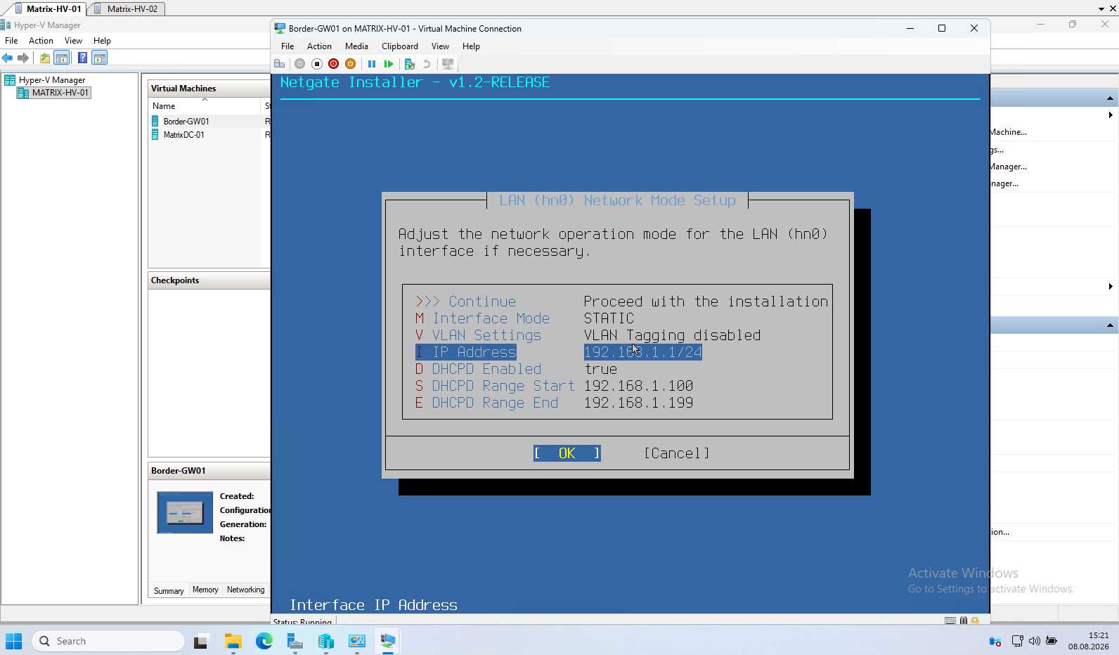
Note: DHCP is intentionally disabled because the Windows Server 2025 domain controller deployed later in this guide will provide DHCP services for the lab. Until then, configure all virtual machines with static IP addresses.
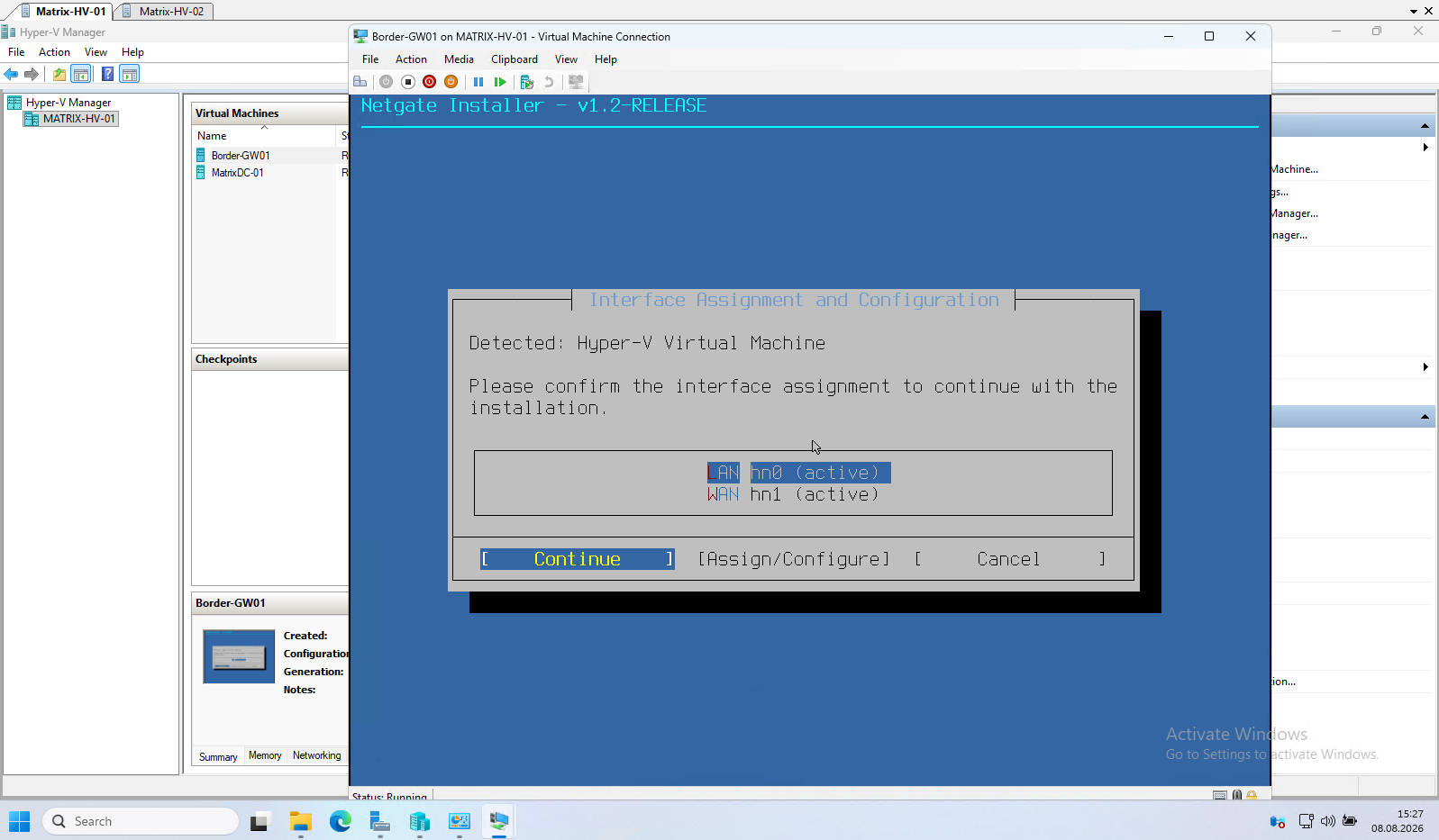
Finally, verify that the interface assignments are correct before continuing with the installation. In our lab, hn0 is assigned as the LAN interface and hn1 as the WAN interface, matching the Hyper-V virtual switches configured earlier.
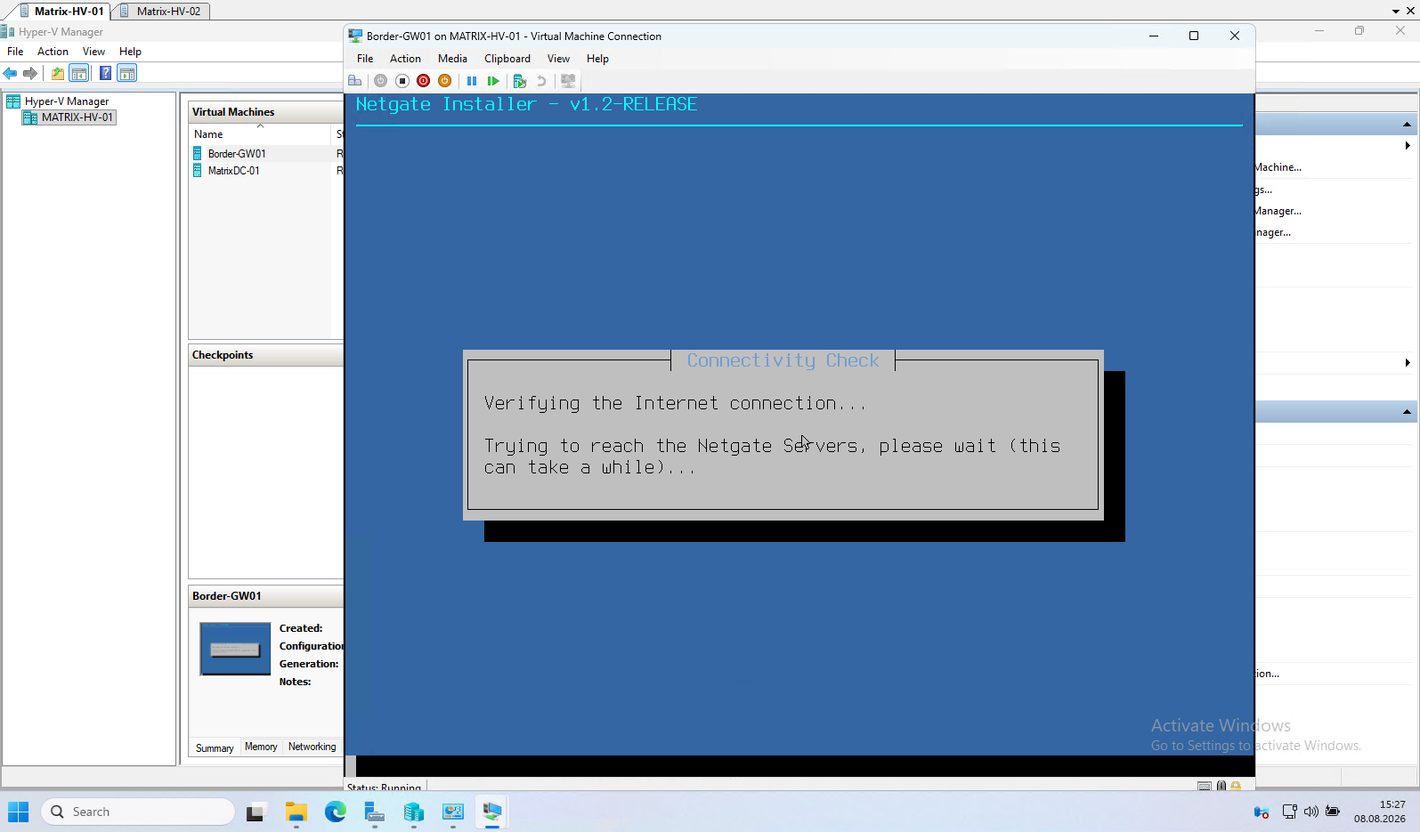
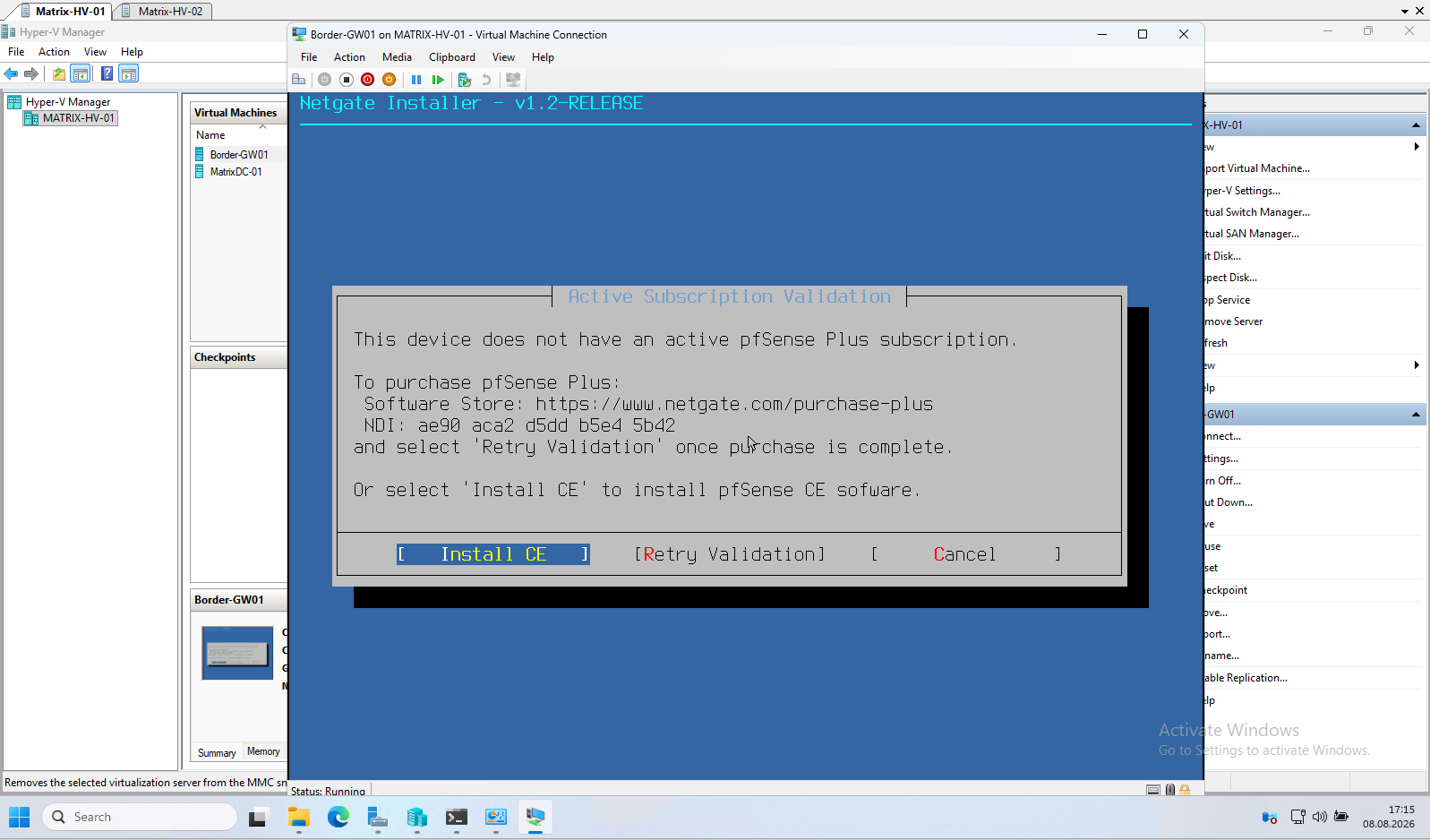
After assigning VLAN ID 100 to the pfSense WAN virtual network adapter, the connectivity check succeeds and the installer is able to reach the Netgate servers. Since no active pfSense Plus subscription is associated with the virtual machine, the installer offers the option to continue by installing the free pfSense Community Edition (CE) instead.
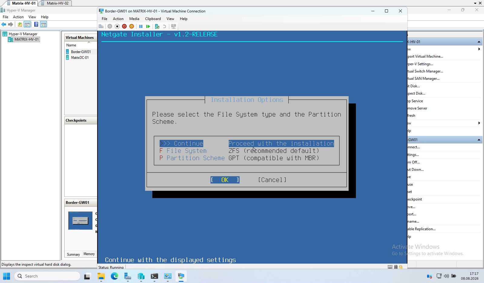
For the installation, leave the default options selected. ZFS is the recommended file system for pfSense, and the GPT partition scheme is used by default for modern UEFI-based systems such as Hyper-V Generation 2 virtual machines.
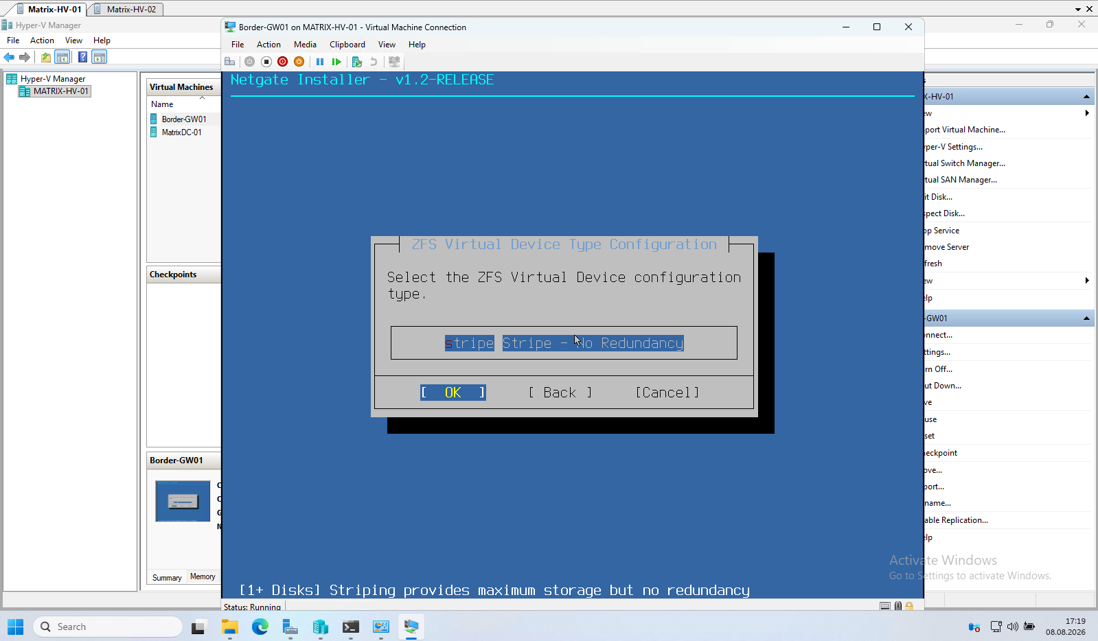
Since the virtual appliance uses only a single virtual disk, leave the default Stripe (No Redundancy) option selected. ZFS redundancy levels such as mirrors or RAID-Z are intended for systems with multiple disks and provide no benefit in this lab environment.
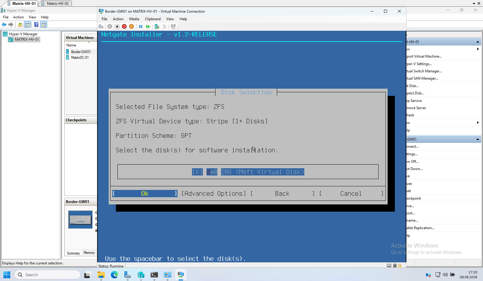
The installer automatically detects the available virtual disk and selects it for the installation. Since the virtual appliance uses only a single 20 GB virtual disk, simply leave the default selection and continue with the installation.
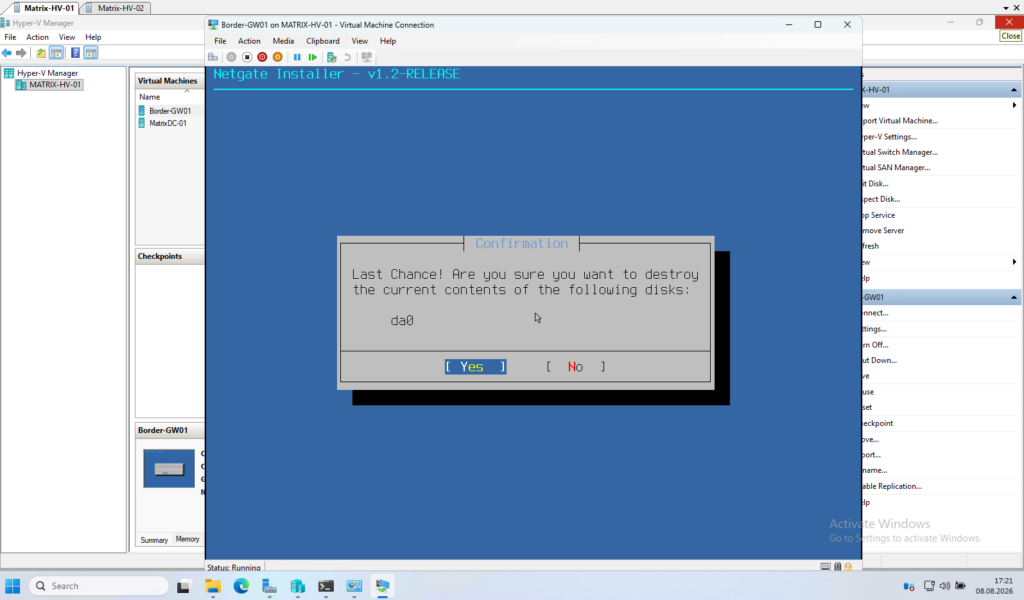
The installer displays a final confirmation before the selected disk is repartitioned and formatted. Since this is a newly created virtual disk dedicated to the pfSense appliance, confirm the operation by selecting Yes to start the installation.
Next, select the pfSense CE release to install. In this example, I use the latest stable version (2.8.1), which provides the most recent production-ready features, bug fixes, and security updates.
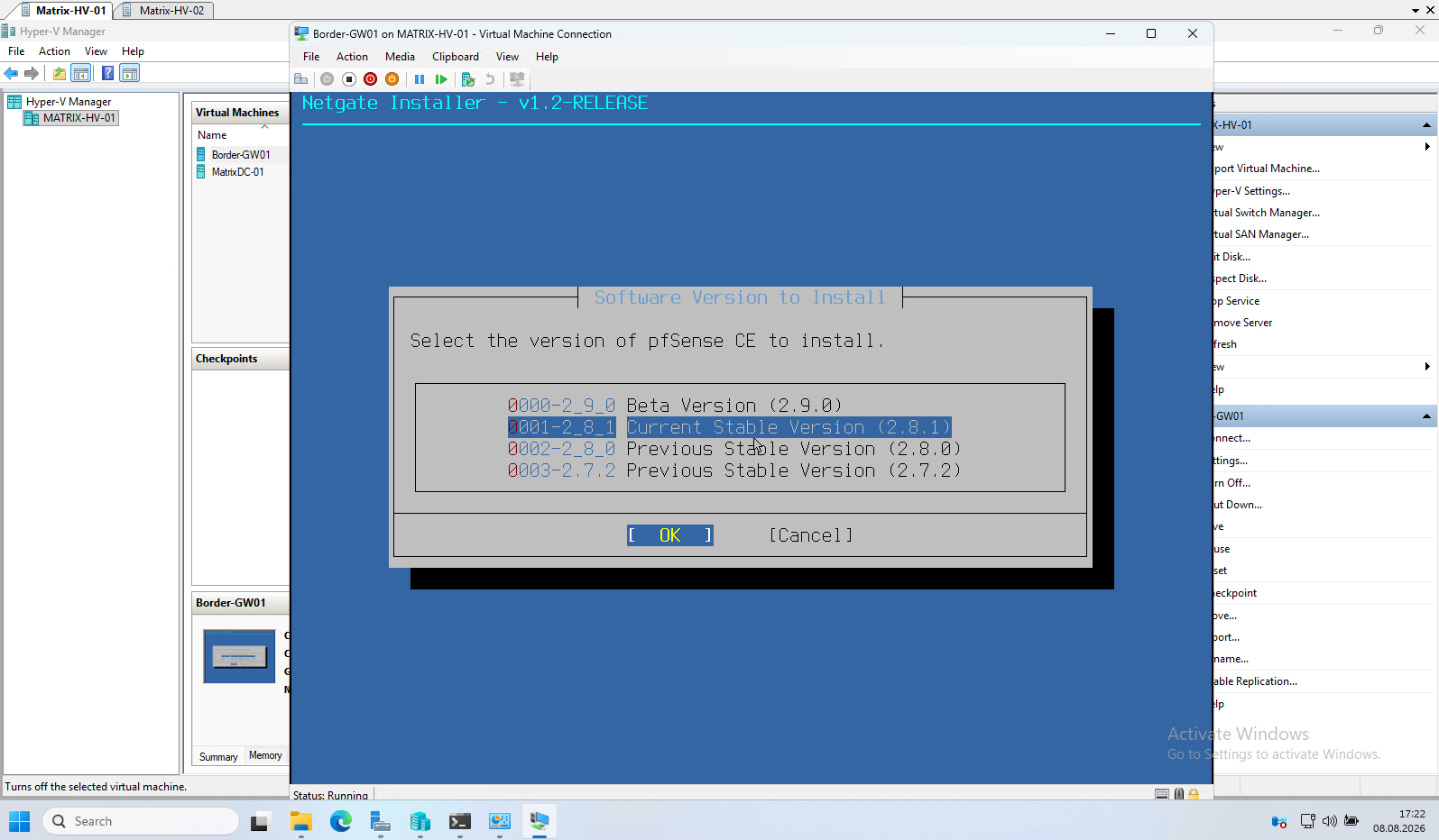
The installer now downloads and installs the required pfSense CE packages from the Netgate repositories. Depending on your Internet connection, this step may take a few minutes to complete.
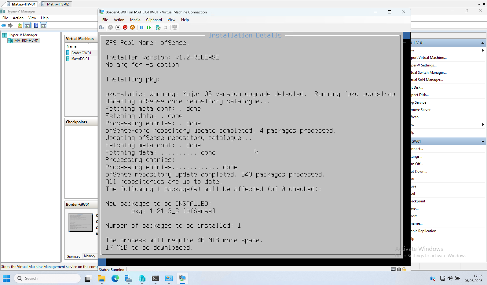
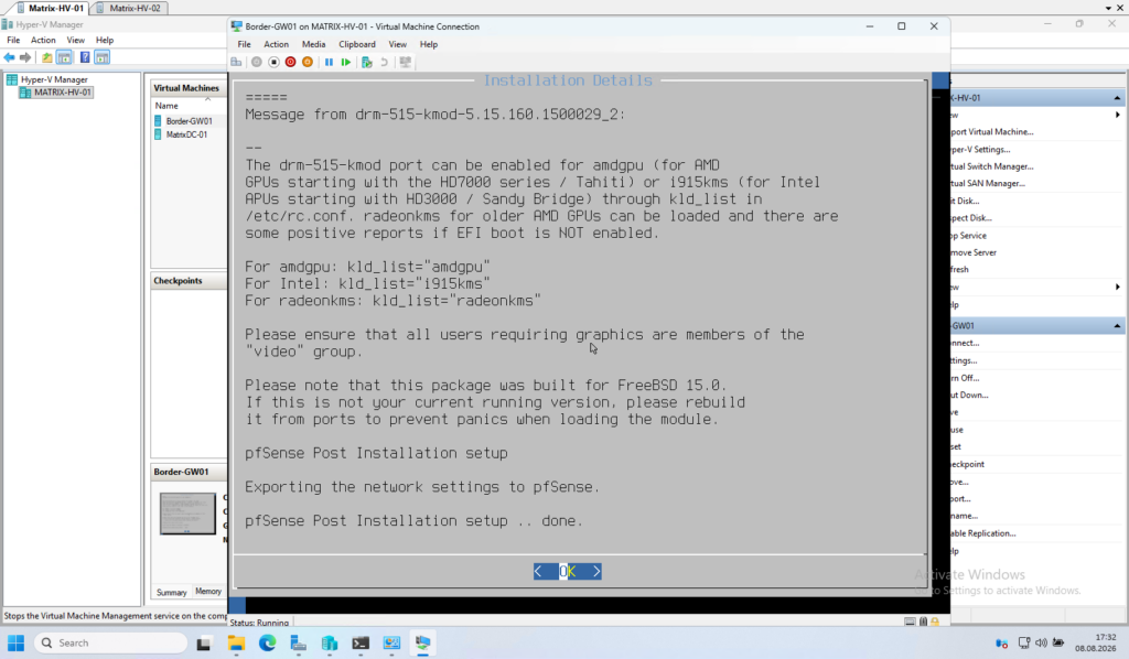
The installation is now complete. During the final post-installation step, pfSense stores the previously configured network interface assignments and prepares the system for its first boot.
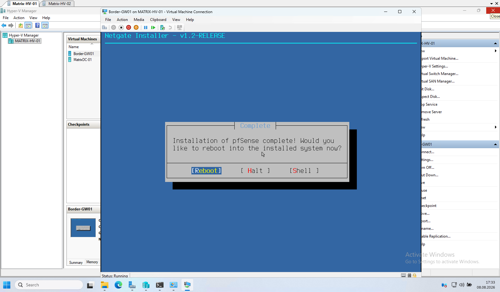
With the installation complete, select Reboot to start the newly installed pfSense CE system. The appliance is now ready for its initial startup and configuration.
After the reboot, pfSense starts with the previously configured interface assignments.
In this example, the WAN interface receives an IP address from the FRITZ!Box via DHCP, while the LAN interface is configured with the static IP address 10.0.0.1/24, which will serve as the default gateway for the lab environment.
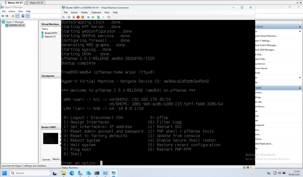
The default credentials for a fresh pfSense CE installation are:
- Username:
admin - Password:
pfsense
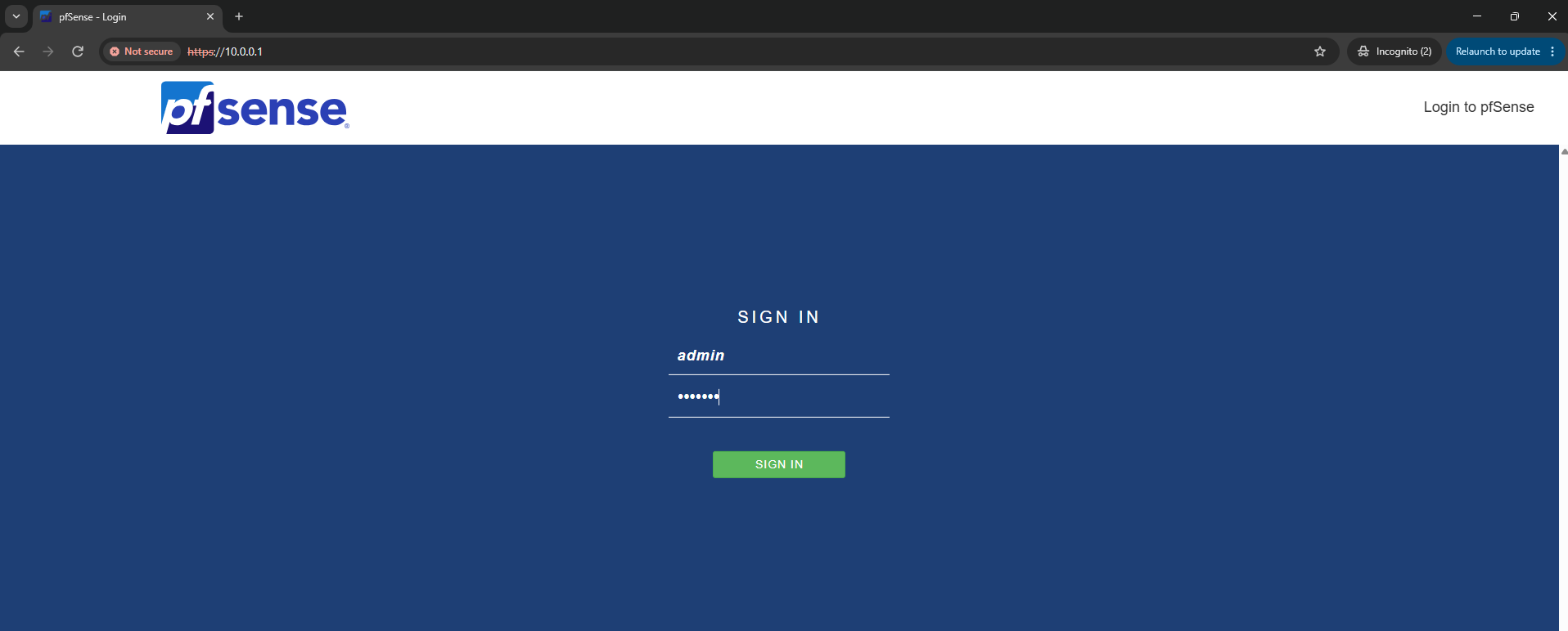
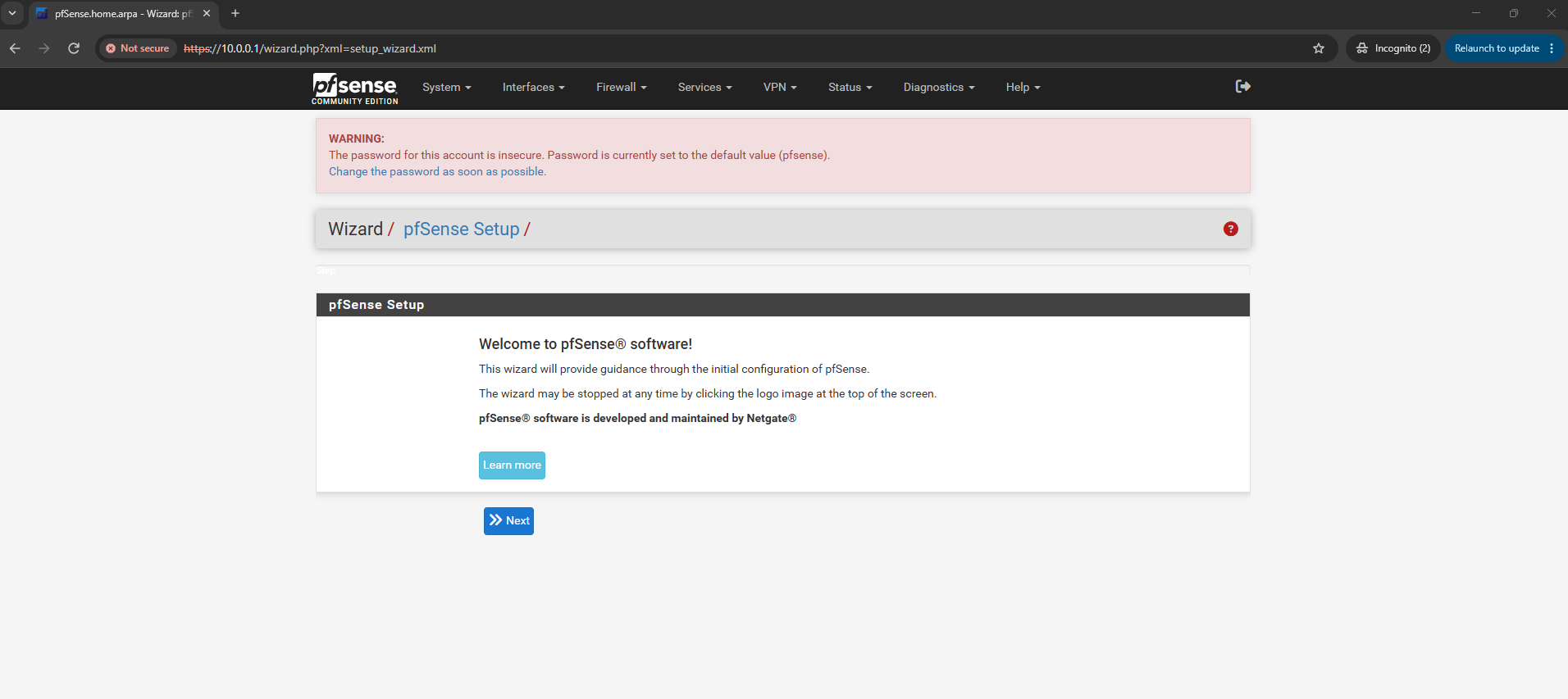
After logging in for the first time via the web interface (https://10.0.0.1 in your lab), the Setup Wizard will prompt you to configure basic settings and you should change the default password to something secure.
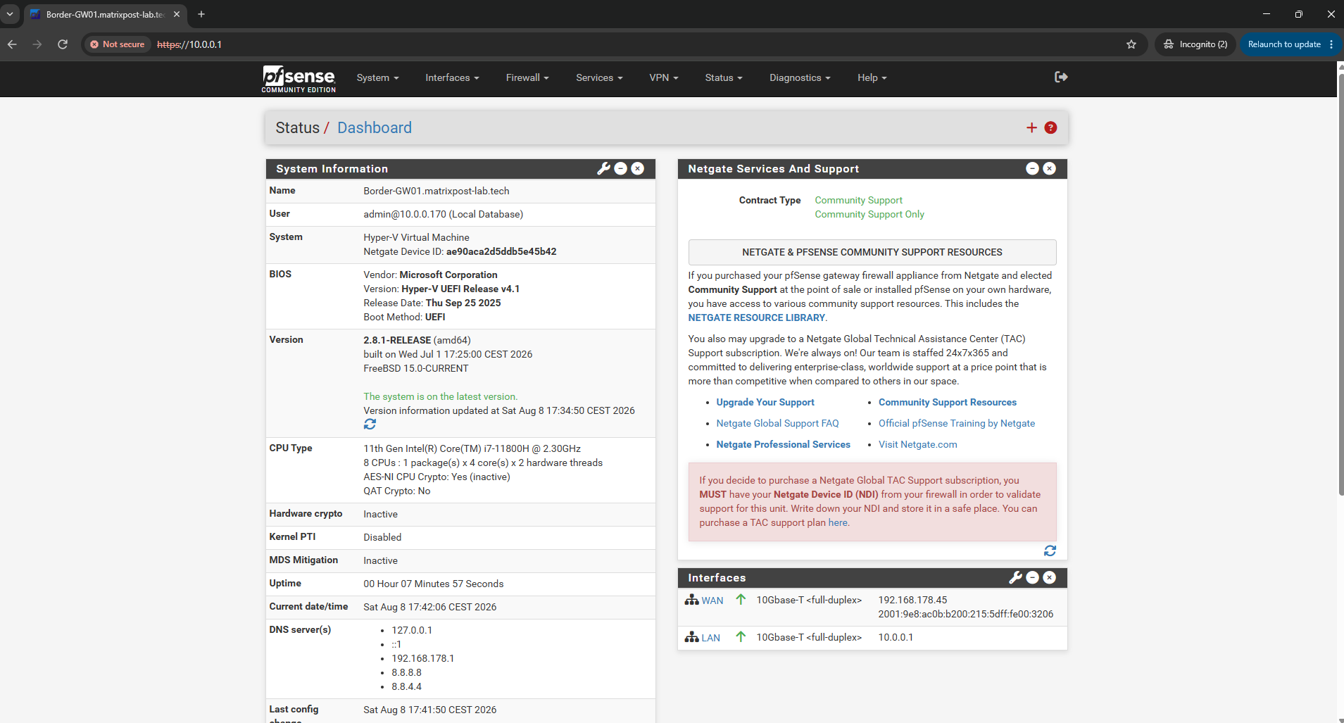
By default, pfSense creates firewall rules that allow all outbound traffic from the LAN interface. This enables clients on the internal network to access the Internet immediately after installation without requiring any additional firewall configuration.
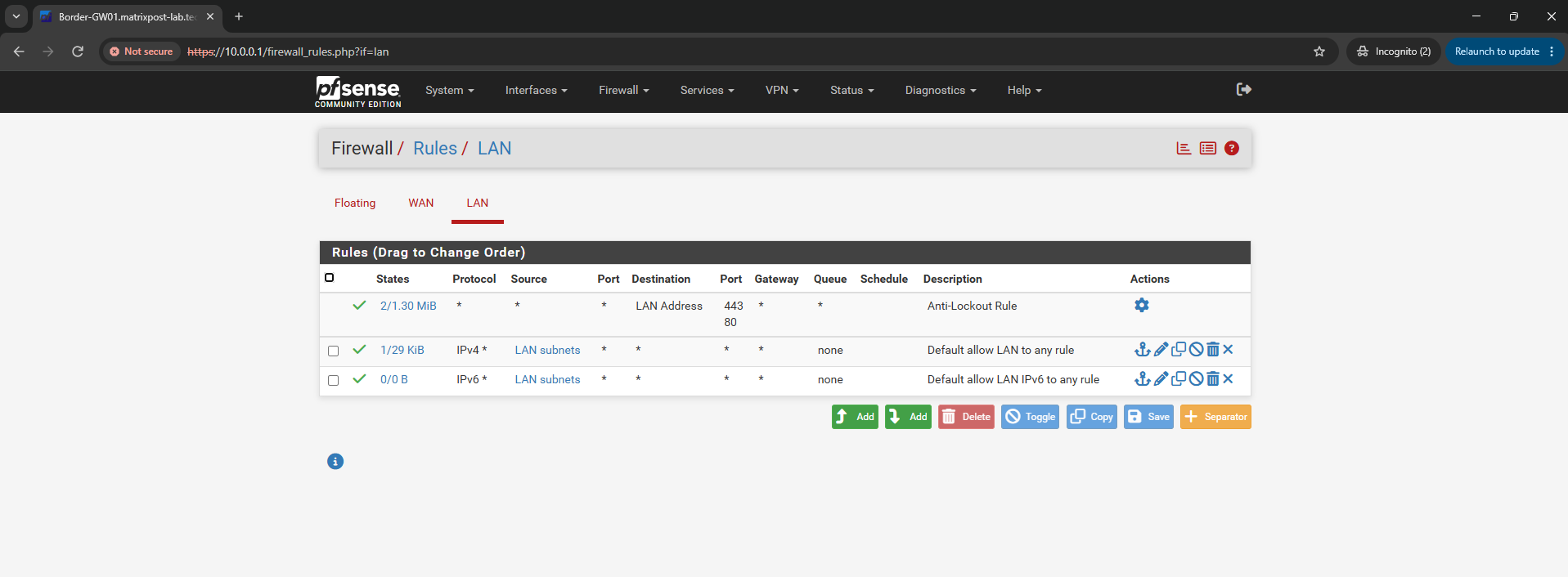
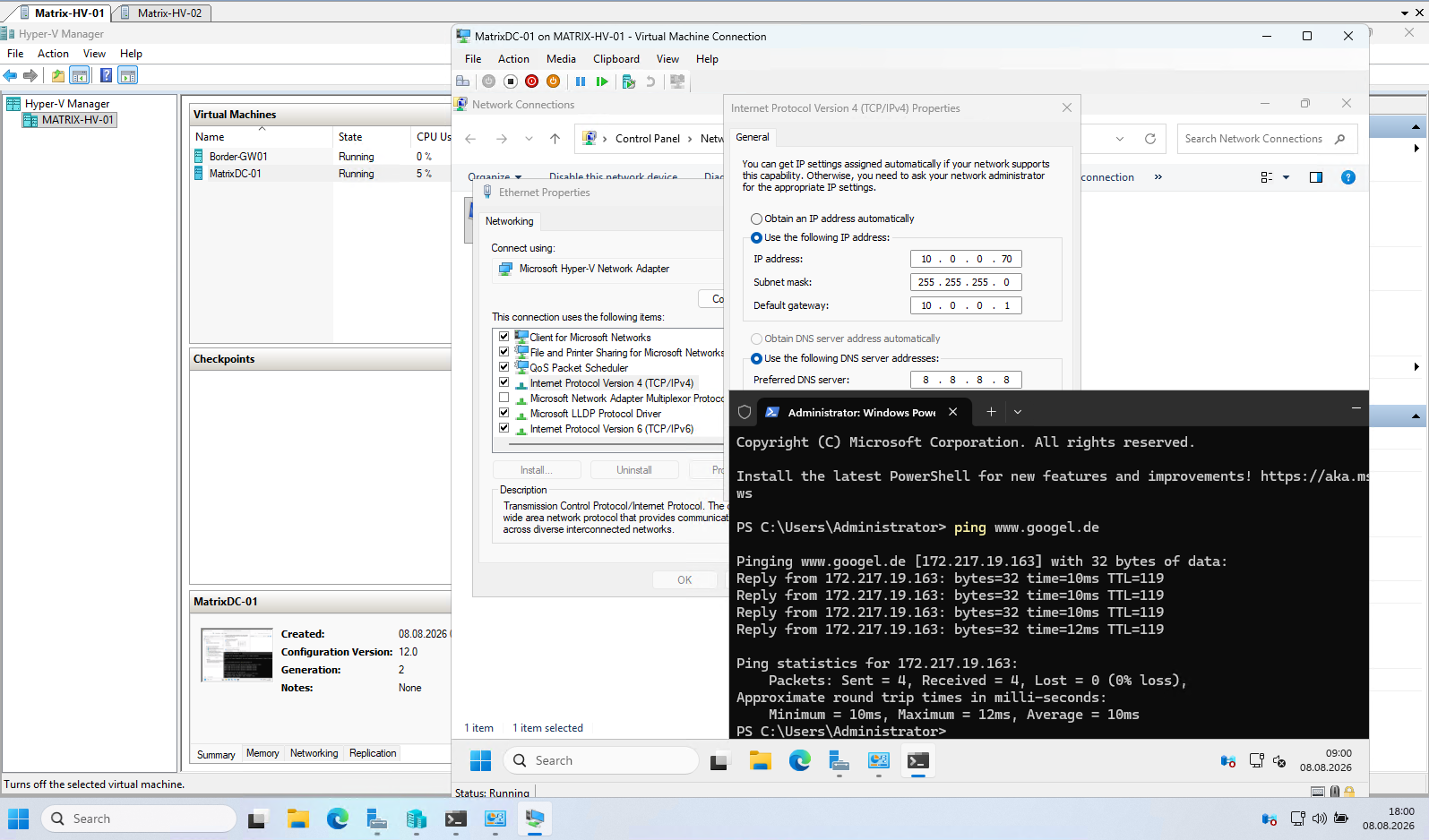
At this point, the initial lab infrastructure is already operational, and the virtual machines have full Internet connectivity through the pfSense firewall.
The only remaining prerequisite before continuing with the Hyper-V networking configuration is to promote the Windows Server virtual machine to an Active Directory Domain Controller, as shown in the next section.
Installing the Active Directory Domain Services (AD DS) Role and Promoting the Server to a Domain Controller
With Internet connectivity now available, the next step is to install the Active Directory Domain Services (AD DS) role and promote the server to the first Domain Controller of our lab environment. This domain controller will provide Active Directory, DNS, and later also DHCP services for the Hyper-V infrastructure.
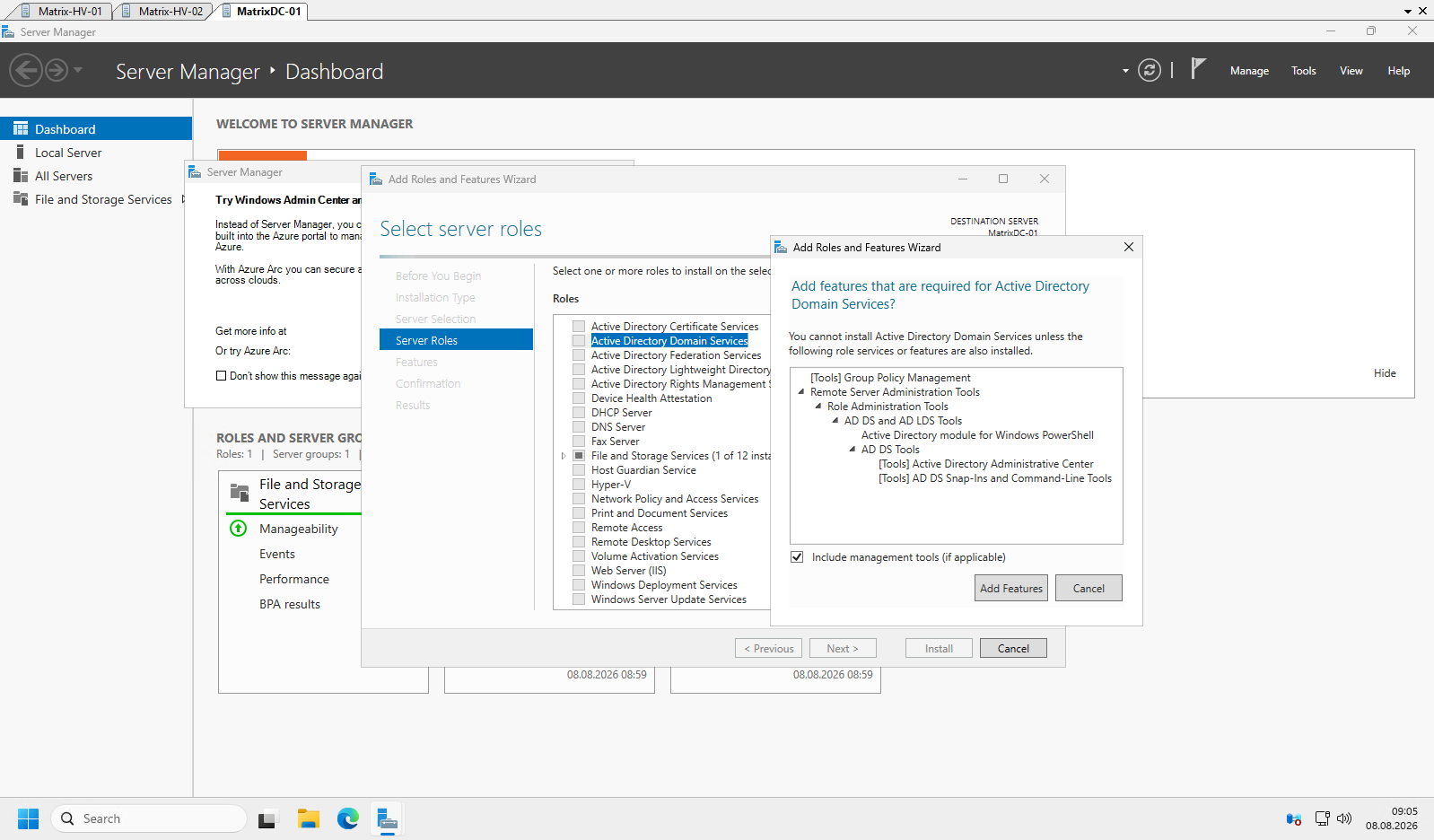
When selecting the Active Directory Domain Services (AD DS) role, Windows Server automatically detects and offers to install the required management tools and dependencies. Accept the defaults by clicking Add Features, as these components are required to deploy and manage Active Directory.
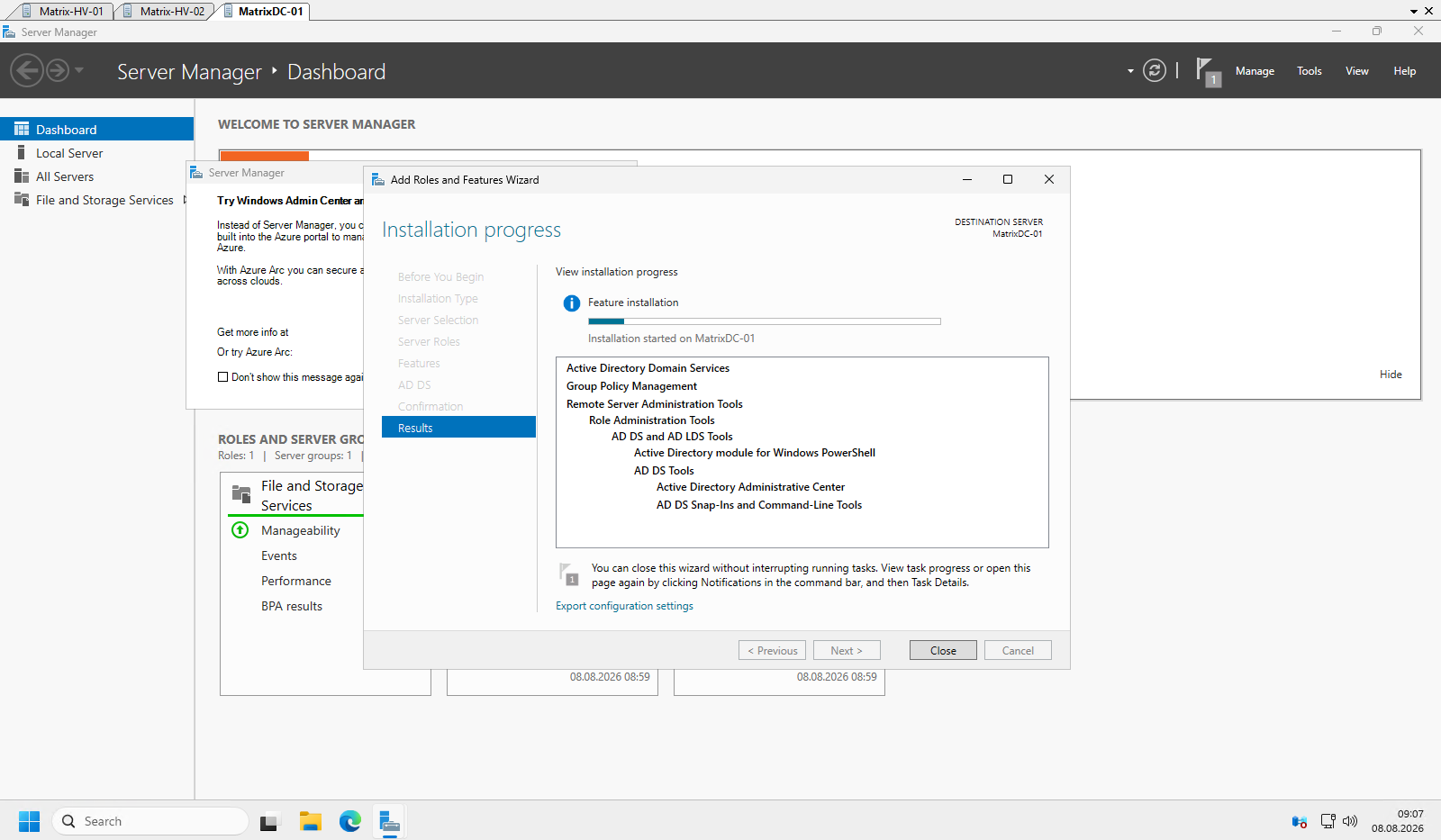
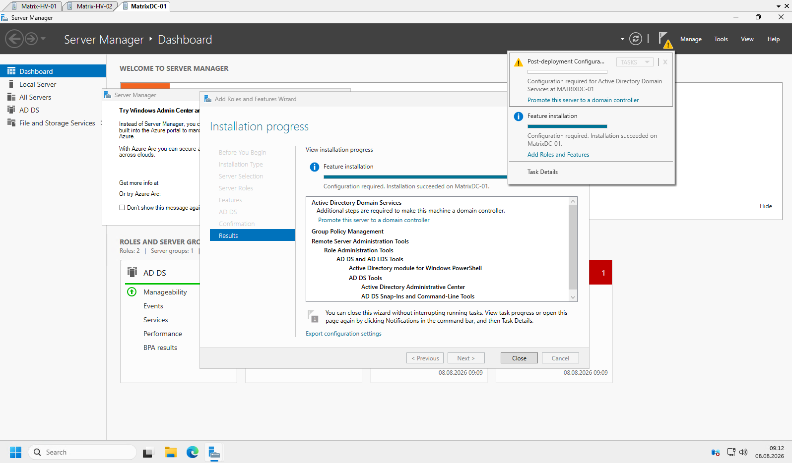
After the required components have been installed, the server is ready to be promoted to a Domain Controller.
Click the Promote this server to a domain controller notification in Server Manager to launch the Active Directory Domain Services Configuration Wizard.
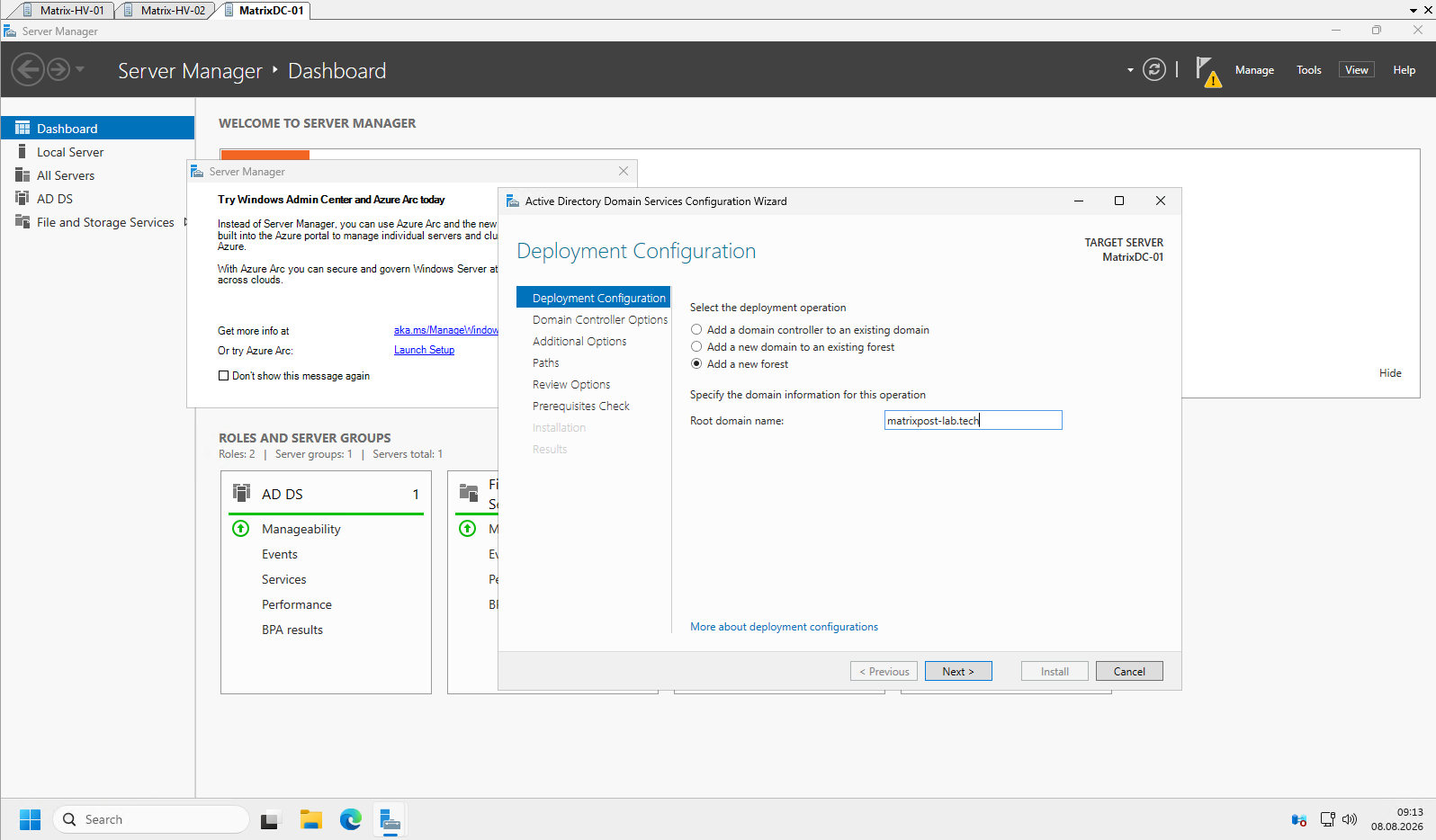
Because this is the first Domain Controller in the lab, select Add a new forest and specify the fully qualified domain name (FQDN) for the new Active Directory forest.
In this lab, I use matrixpost-lab.tech as the root domain name.
Select the appropriate forest and domain functional level. Since this is a new lab environment built with Windows Server 2025, I use the latest available functional level.
Leave DNS Server and Global Catalog (GC) enabled, specify a strong Directory Services Restore Mode (DSRM) password, and then click Next.

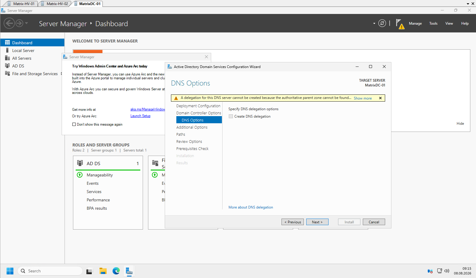
Because this is the first domain controller in a new forest, no parent DNS zone exists yet.
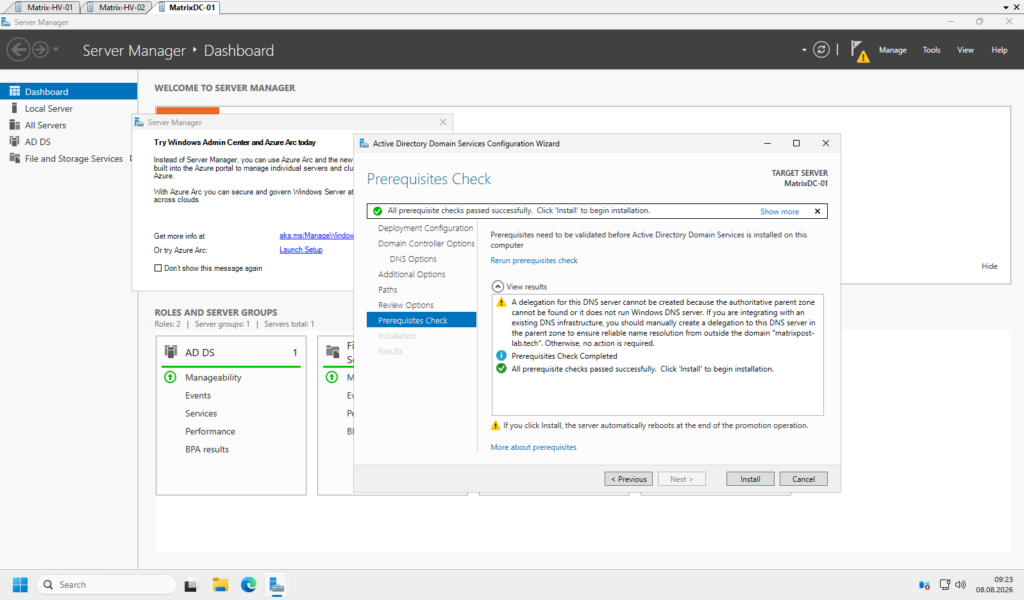
The DNS delegation warning can safely be ignored in most on-premises Active Directory environments. A delegation is only required when an existing authoritative parent DNS zone is managed on another DNS server and must delegate the child zone to this DNS server, which is typically not the case. Click Next to continue.
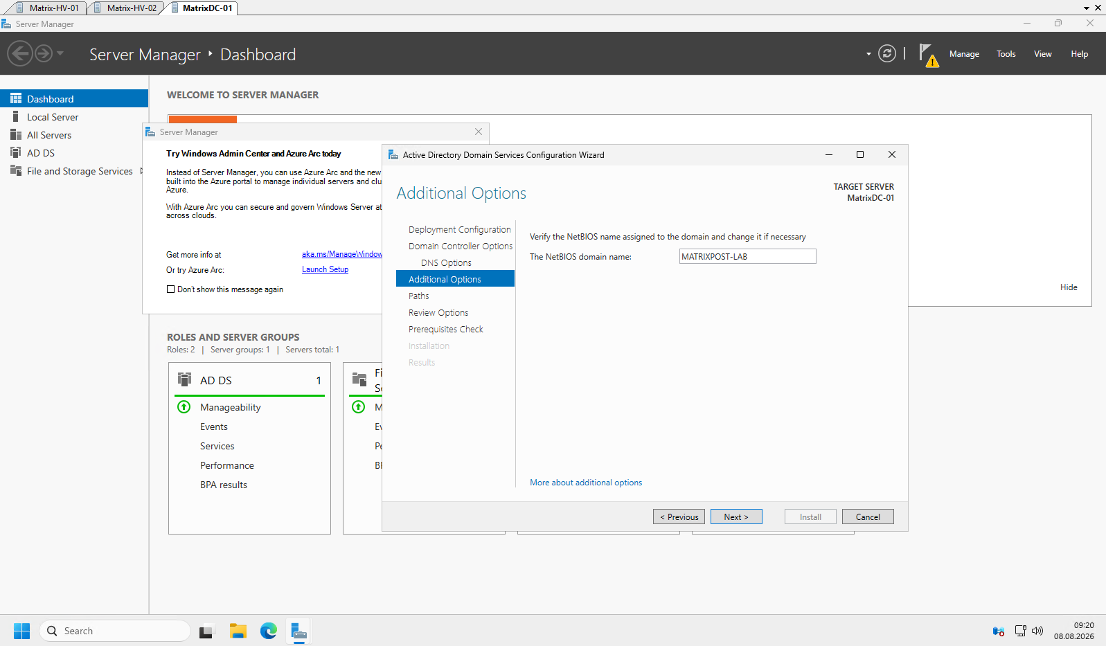
By default, the NetBIOS domain name is derived automatically from the DNS domain name. Unless you have a specific requirement for
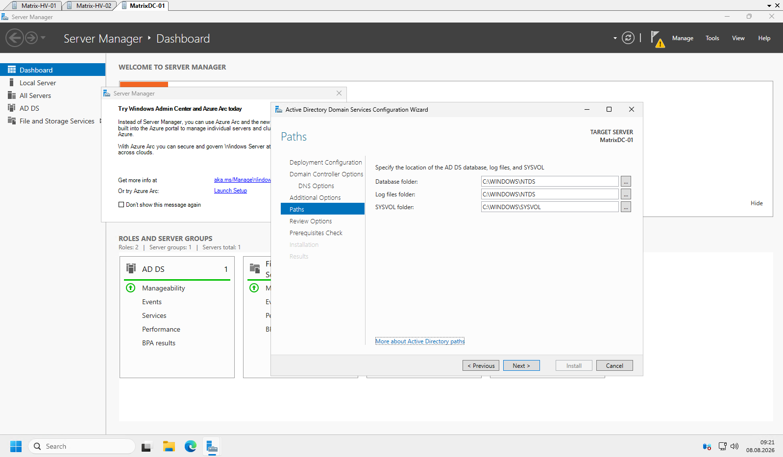
Unless you have specific requirements to separate the Active Directory database, log files, or SYSVOL onto dedicated volumes, the default locations are appropriate and can be accepted by clicking Next.
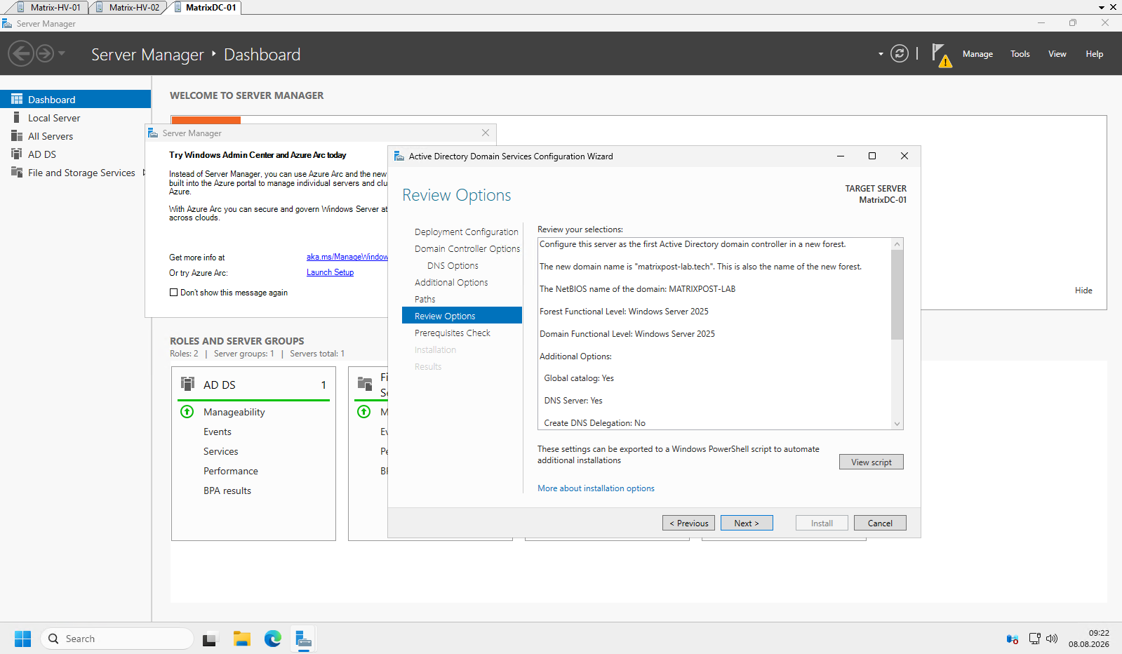
Review the selected configuration before proceeding. If everything is correct, click Next to continue. The configuration can also be exported as a PowerShell script for automated Active Directory deployments.
The prerequisite check verifies that all requirements for promoting the server to a domain controller are met. In this example, the validation completes successfully; the remaining DNS delegation warning is expected and can safely be ignored. Click Install to begin the domain controller promotion.
The server is now promoted to the first domain controller of the new Active Directory forest. During the installation, the required Active Directory database, SYSVOL, DNS configuration, and directory partitions are created automatically.
During the promotion, Active Directory automatically creates the required directory partitions, including the Domain, Configuration, and Schema partitions. These partitions store domain-specific objects, forest-wide configuration data, and the Active Directory schema, and are automatically replicated to other domain controllers as required.
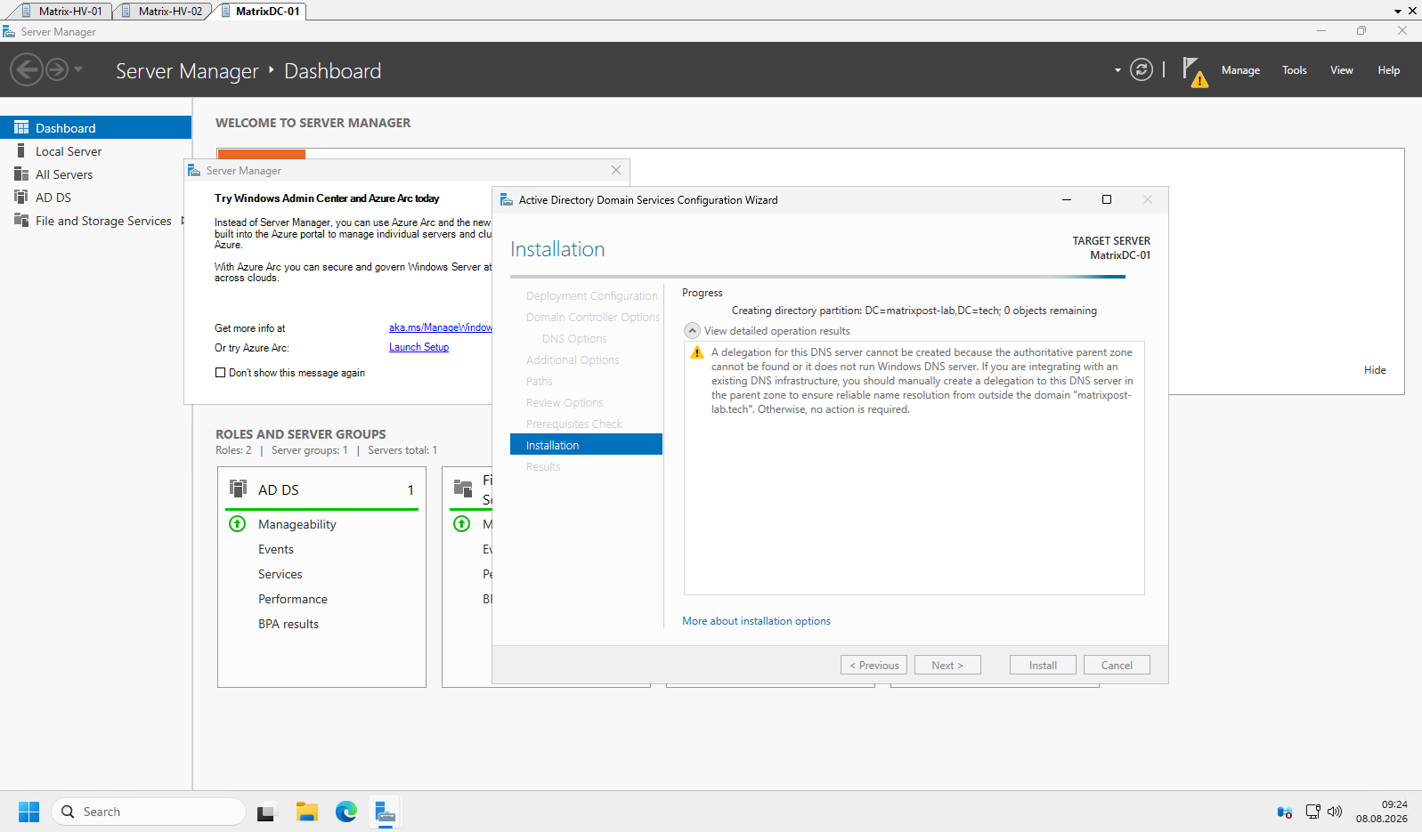
The server will reboot automatically once the promotion has completed.
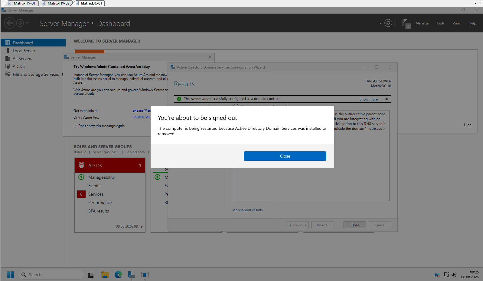
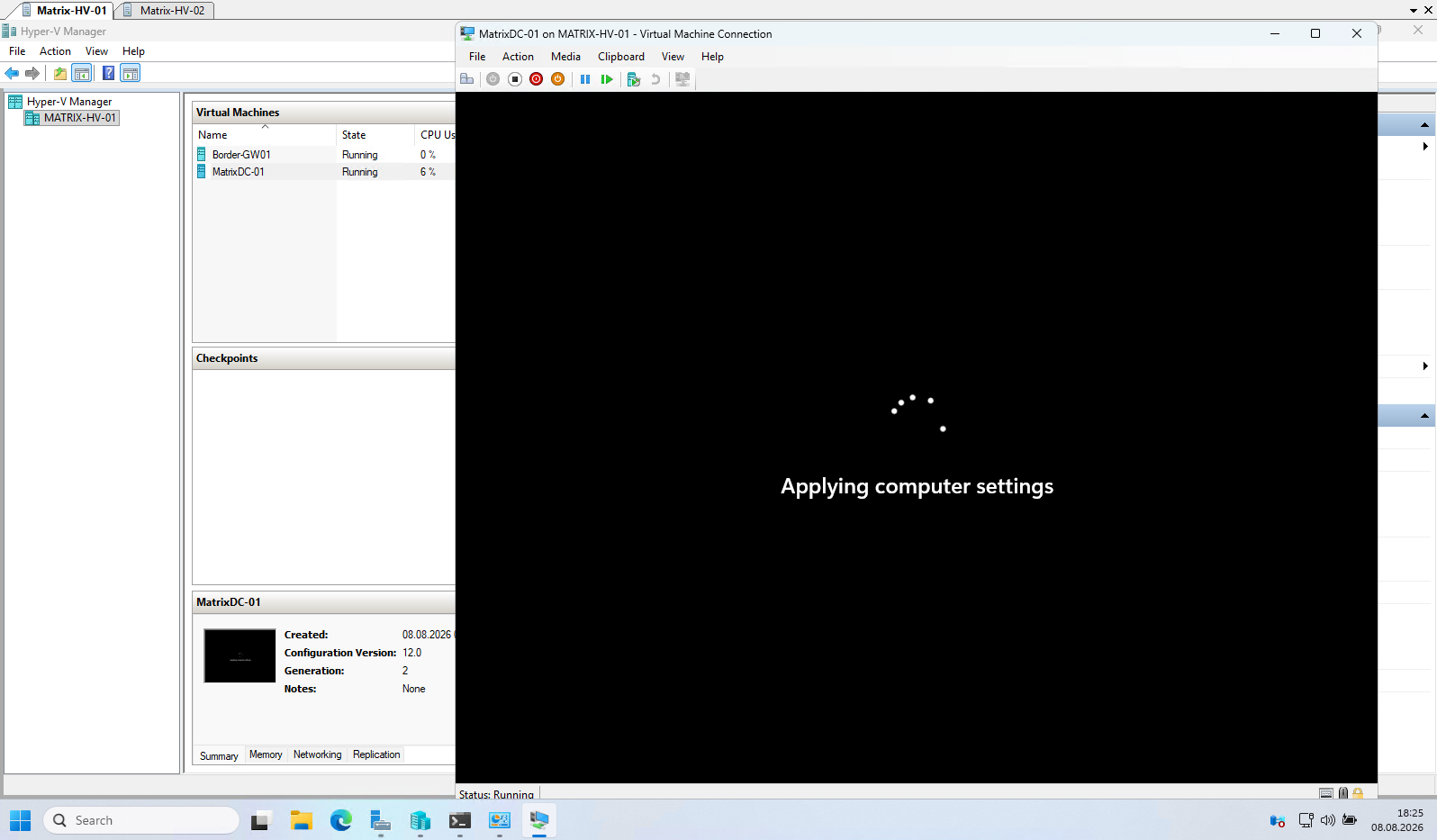
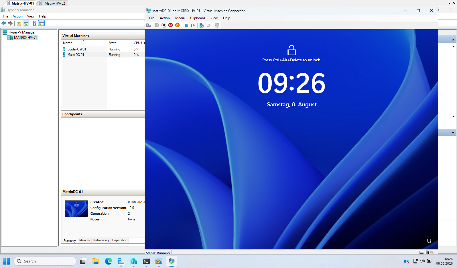
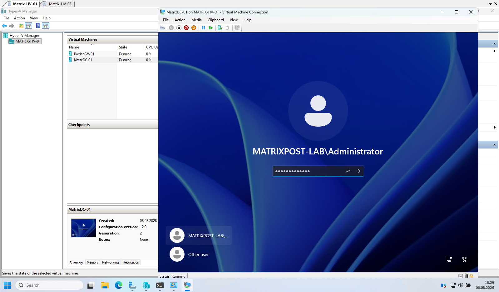
After the server has been promoted to a domain controller, local user accounts are no longer available for interactive sign-in because the local Security Accounts Manager (SAM) is replaced by Active Directory.
In this example, where this is the first and only domain controller, sign in by using the built-in Administrator account, which is now a member of the Enterprise Admins, Domain Admins, and Schema Admins groups.
After the installation completes and the server restarts, you can verify the successful promotion by opening Active Directory Users and Computers. The new domain is now available, and the server appears in the Domain Controllers organizational unit (OU) as the first domain controller and Global Catalog (GC) server.
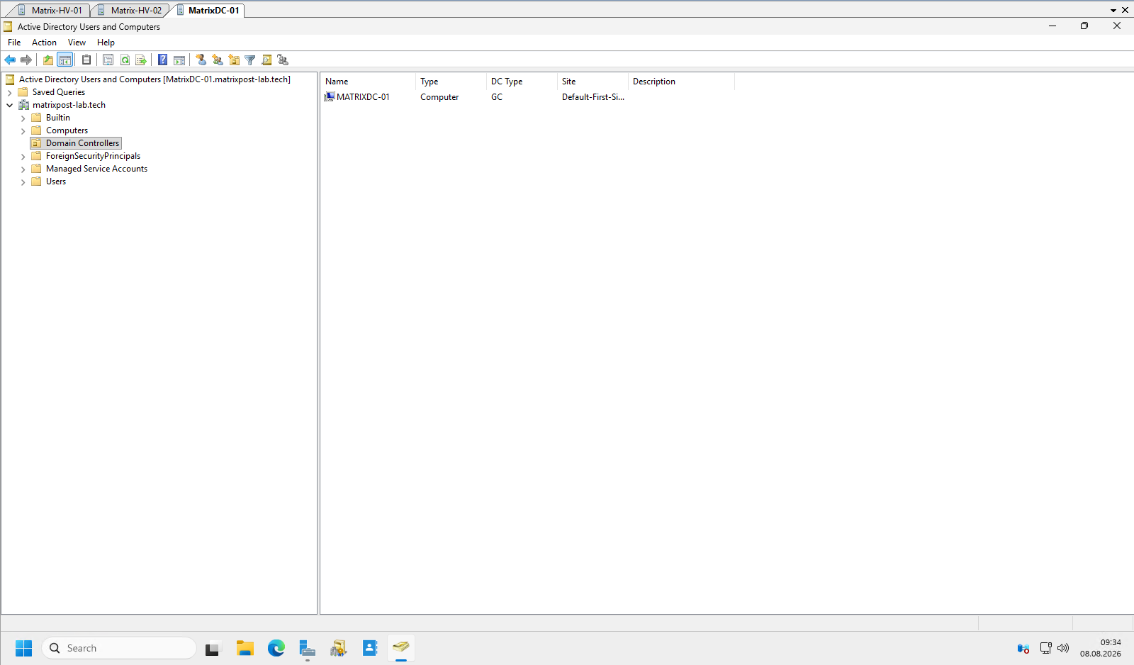
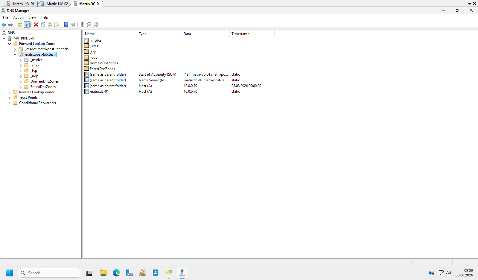
During the domain controller promotion, Windows automatically installs and configures the integrated Active Directory DNS service.
The required forward lookup zone, SRV records, and the ForestDnsZones and DomainDnsZones application partitions are created automatically, enabling clients and domain controllers to locate Active Directory services through DNS.
Links
Plan for Hyper-V networking in Windows Server
https://learn.microsoft.com/en-us/windows-server/virtualization/hyper-v/plan/plan-hyper-v-networking-in-windows-serverHyper-V Virtual Switch
https://learn.microsoft.com/en-us/windows-server/virtualization/hyper-v/virtual-switchNetwork recommendations for Hyper-V in a failover cluster
https://learn.microsoft.com/en-us/windows-server/virtualization/hyper-v/failover-cluster-network-recommendationsSwitch Embedded Teaming (SET)
https://learn.microsoft.com/en-us/azure/azure-local/concepts/host-network-requirements/#switch-embedded-teaming-setHyper-V virtualization in Windows Server and Windows
https://learn.microsoft.com/en-us/windows-server/virtualization/hyper-v/overviewHyper-V Architecture
https://learn.microsoft.com/en-us/windows-server/virtualization/hyper-v/architecturePlan for Hyper-V security in Windows Server
https://learn.microsoft.com/en-us/windows-server/virtualization/hyper-v/plan/plan-hyper-v-security-in-windows-serverInstall Hyper-V
https://learn.microsoft.com/en-us/windows-server/virtualization/hyper-v/get-started/install-hyper-vWhat is Nested Virtualization?
https://learn.microsoft.com/en-us/windows-server/virtualization/hyper-v/nested-virtualizationHyper-V Virtual Fibre Channel
https://learn.microsoft.com/en-us/windows-server/virtualization/hyper-v/plan/virtual-fibre-channel-for-hyper-vGuarded fabric and shielded VMs
https://learn.microsoft.com/en-us/windows-server/security/guarded-fabric-shielded-vm/guarded-fabric-and-shielded-vms-top-node